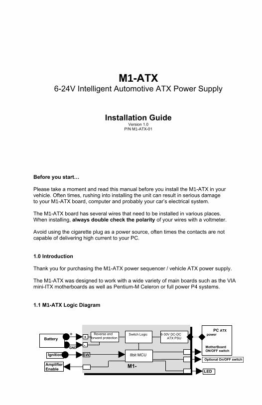
GND + Switch Logic 6-30V DC-DC ATX PSU PC ATX power MotherBoard ON/OFF switch M1- Battery Ignition - SW + J86 LED J54 J62 8bit MCU Amplifier Enable J98 Reverse and forward protection Optional On/OFF switch M1-ATX 6-24V Intelligent Automotive ATX Power Supply Installation Guide Version 1.0 P/N M1-ATX-01 Before you start… Please take a moment and read this manual before you install the M1-ATX in your vehicle. Often times, rushing into installing the unit can result in serious damage to your M1-ATX board, computer and probably your car’s electrical system. The M1-ATX board has several wires that need to be installed in various places. When installing, always double check the polarity of your wires with a voltmeter. Avoid using the cigarette plug as a power source, often times the contacts are not capable of delivering high current to your PC. 1.0 Introduction Thank you for purchasing the M1-ATX power sequencer / vehicle ATX power supply. The M1-ATX was designed to work with a wide variety of main boards such as the VIA mini-ITX motherboards as well as Pentium-M Celeron or full power P4 systems. 1.1 M1-ATX Logic Diagram
Transcript
GND
+ Switch Logic 6-30V DC-DC ATX PSU
PC ATX power
MotherBoard ON/OFF switch
M1-
Battery
Ignition
-
SW
+
J86
LED J54
J62
8bit MCU
Amplifier Enable
J98
Reverse and forward protection
Optional On/OFF switch
M1-ATX6-24V Intelligent Automotive ATX Power Supply
Installation GuideVersion 1.0
P/N M1-ATX-01
Before you start…
Please take a moment and read this manual before you install the M1-ATX in your vehicle. Often times, rushing into installing the unit can result in serious damage to your M1-ATX board, computer and probably your car’s electrical system.
The M1-ATX board has several wires that need to be installed in various places.When installing, always double check the polarity of your wires with a voltmeter.
Avoid using the cigarette plug as a power source, often times the contacts are not capable of delivering high current to your PC.
1.0 Introduction
Thank you for purchasing the M1-ATX power sequencer / vehicle ATX power supply.
The M1-ATX was designed to work with a wide variety of main boards such as the VIA mini-ITX motherboards as well as Pentium-M Celeron or full power P4 systems.
1.1 M1-ATX Logic Diagram
1.2 M1-ATX Connection diagram
M2-ATX, top view
Power Input ConnectorsJ1 Battery + (un-switched battery, positive)J3 Ignition (switched battery, positive. Can test by connecting it to Battery +)J4 Battery - (negative)
Controls and SettingsJ6 Controls amplifier via remote ON/OFF. Left pin is RMT, Right pin is GNDJ8 To motherboard ON/OFF switchJ10 User jumper settings (A,B,C,D)J9 To external ON/OFF switch (optional, J8 is in parallel with J9)
Power Output ConnectorsJ2 Optional P4-12V powerJ7 ATX power connector (to motherboard)J5 To LED (optional)
NOTE: “If HARDOFF is set to “never”, M2-ATX will automatically shut down when battery voltage is below 11.2V for more than 1 minute in order to prevent ‘deep discharge’ situations.
Mode “0” is regular ATX power supply mode, no power sequencing provided, can be used for non vehicle applications.
Avoid using HARDOFF = Never, can severely discharge your battery if PC. Suggested modes are: 1, 2, and 4.
1.2 Power challenges in a Vehicle PC
The 5V Standby Problem: One of most difficult tasks of operating a PC in a vehicle is power consumption while the computer is OFF. Even when your computer is OFF, it will still consume about 100mA on the 5V rail. All power supplies provide 5VSB (5V standby) so that the motherboard can issue at least a PSON signal. When the computer is in the suspend mode, it will consume even more power, because the RAM needs to be powered at all times. No matter how big your battery is, it will eventually drain your battery in a matter of days.
M2-ATX User Guide Page 2
The M2-ATX is addressing these issues by cutting off the 5VSB rail after a pre-defined amount of time (see jumper chart, HARDOFF). When 5VSB is always active (HARDOFF=Never), M1-ATX constantly monitors the battery levels. When battery level drops below 11V for more than one minute, M1-ATX will shut down and re-activate only when the input voltage is > 11V.
Engine Cranks, under-voltage and over-voltage situations. Another difficult task is maintaining stable 3.3V, 5V, 12V and -12V power to your PC. While car batteries are rated at 12V, they actually provide voltages in between 7-11V (engine cranks) or as high as 80 volts (load dump). Most of the times, your battery will stay at 13.5V (while car is running) but extra precautions need to take place in order to prevent such situations. M1-ATX can operate as low as 6V and as high as 28V while providing strict regulation on all rails along with input voltage clamping and reverse protection.
Loud amplifier pops when PC starts. If your PC is connected to your car amplifier, you will hear a loud pop when the computer is first started. The M1-ATX has an ‘anti-thump’ control that will keep your amp OFF while the PC starts. Simply connect J6 to your amplifier remote control pins to activate the ‘anti-thump’ feature.
2.0 Mode of operation
The M1-ATX performs several timing routines and takes actions as follows:(NOTE: When all config jumpers are removed, M1-ATX will be in the “dumb PSU mode”, no ignition timing, no HARDOFF. M1-ATX will send a gratuitous “ON” pulse to the M/B when power is applied for the first time. Do not connect J8/J9 to the M/B on/off switch if you don’t want your PC to be started automatically.
1) Ignition=OFF. Nothing happens. M2-ATX is waiting for ignition signals.
2) Ignition=ON. M2-ATX waits for 2-3 seconds then turns on the 5Vsb rail. After another second M2-ATX sends an “ON” signal to the motherboard via the 2 wires connected to the motherboard’s ON/OFF pins. The motherboard will turn ON and your system should start booting.
3) Ignition=ON during driving. Your computer will remain ON.
4) Ignition=OFF. M2-ATX waits for “OFFDELAY” in seconds (see jumper chart on Page 2) and then it turns the motherboard OFF by sending a signal to the motherboard’s ON/OFF switch. Your computer should turn off gracefully (shutdown procedure). During this time, power will still be available for your PC to perform shutdown.
5) 5VSB will still be provided for another “HARDOFF” seconds (see jumper chart). In the event where the shutdown process is longer than “OFFDELAY” (windows gets frozen, etc), power will be shut down hard, turning off all power rails. If “HARDOFF” is set to ‘NEVER”, the PSU will always provide 5VSB, therefore the PC can also be used in the SLEEP mode. During the HARDOFF procedure, the battery levels will be constantly monitored to prevent deep discharge situations.
6) M1-ATX will go to step 1, if ignition is tuned ON again.
3.0 Troubleshooting
a) Motherboard is not turning ON.
M2-ATX User Guide Page 3
Check input cables. Measure voltage on the un-switched 12V. You should get about 12V. Measure the un-switched pin (red) while turning the car ON/OFF. You should see 12V (car on) or 0V (car off).
b) Motherboard is not turning ON (cont). Check your output cables. Ensure total system power consumption does not exceed the M2-ATX specifications.
c) Motherboard is not turning ON (cont).Make sure that either J8 or J9 is properly connected to the ON/OFF switch of your M/B.
4.0 M2-ATX Characteristics
Minimum Input Operating. voltage 6VMaximum input Operating voltage 24V (clamping will occur at 25-27V)
Deep-Discharge shutdown threshold 11.2VInput current limit (fuse protected) 15A (15A mini-blade fuse)Max Output Power 90 WattsOperating temperature -40 to +85* degrees CelsiusStorage temperature -55 to +125 degrees CelsiusMTBF 192,000 hrs @ 50C, 96,000 hrs @65CEfficiency (Input 9-16V) >94%, all rails combined, 50% load.PCB size 160x45mmInput connectors Faston 0.25” terminal
Output Connector ATX Power 20 pin (Molex P/N 39-01-2200)
*Units starts failing at ~115 Celsius. Operating at temperatures above 85C / 185F will drastically reduce the MTBF. When operating at high temperatures or fanless operation, must reduce PSU load by 25%.
75
78
81
84
87
90
93
96
99
6 8 10 12 14 16 18Vin (V)
12V
rai
l Effi
cien
cy (%
)
Iout = 5AIout = 6AIout = 8A
Maximum Power CharacteristicsOutput Rail Current (Max) Current Peak


![Sequencer 1, Sequencer 2 or Drum - Arturiadownloads.arturia.com/products/beatstep-pro/manual/BeatStepPro... · —Sequencer 1, Sequencer 2 or Drum SHIFT + [>>] = Extend sequence SHIFT](https://static.documents.pub/doc/80x56/5adbc3047f8b9add658e5b6e/sequencer-1-sequencer-2-or-drum-sequencer-1-sequencer-2-or-drum-shift-.jpg)


![Sequencer 1, Sequencer 2 or Drum - medias.arturia.net · —Sequencer 1, Sequencer 2 or Drum SHIFT + [>>] = Extend sequence SHIFT + Knob 1 = Offset value for all active steps ...](https://static.documents.pub/doc/80x56/5b87086c7f8b9aa0218be152/sequencer-1-sequencer-2-or-drum-sequencer-1-sequencer-2-or-drum-shift.jpg)


