Information is subject to change without notice. Nortel Networks reserves the right to make changes in design or components as progress in engineering and manufacturing may warrant. This equipment has been tested and found to comply with the limits for a Class A digital device pursuant to Part 15 of the FCC rules, and the radio interference regulations of Industry Canada. These limits are designed to provide reasonable protection against harmful interference when the equipment is operated in a commercial environment. This equipment generates, uses and can radiate radio frequency energy, and if not installed and used in accordance with the instruction manual, may cause harmful interference to radio communications. Operation of this equipment in a residential area is likely to cause harmful interference in which case the user will be required to correct the interference at their own expense.
SL-1 and Meridian 1 are trademarks of Nortel Networks.
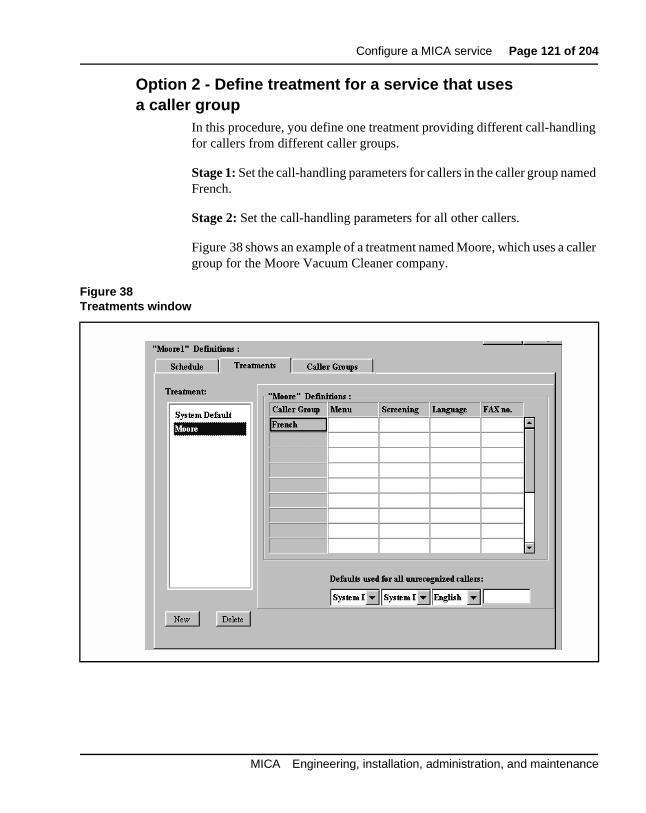
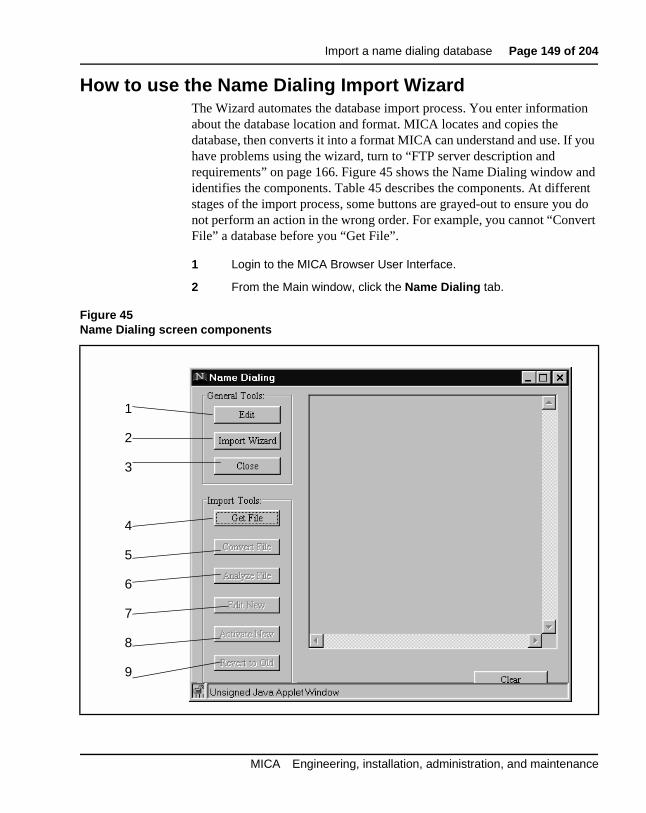
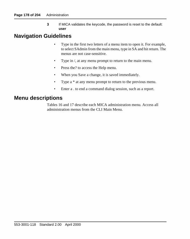
MICA Engineering, installation, administration, and maintenance
Page 3 of 204
4
ase
Revision historyApril 2000
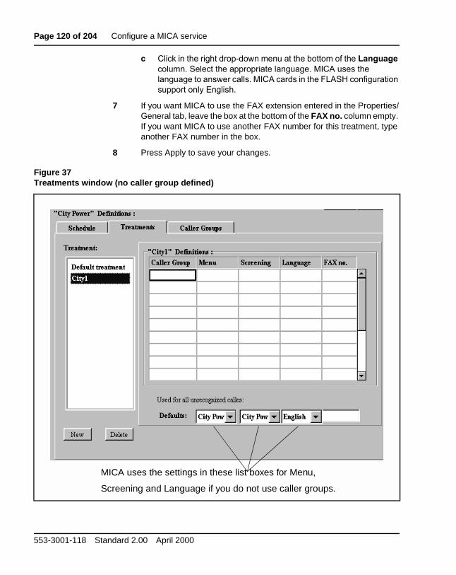
Standard 2.00. This is a global document and is up-issued for X11 Rele25.0x.
July 1999Standard, issue 1.00. First issue of document.
MICA Engineering, installation, administration, and maintenance
MICA Engineering, installation, administration, and maintenance
Page 12 of 204 Contents
553-3001-118 Standard 2.00 April 2000
Page 13 of 204
14
ur
nd
About this documentThis document is a global document. Contact your system supplier or yoNortel Networks representative to verify that the hardware and softwaredescribed is supported in your area.
This document explains how to engineer, install, configure, administer amaintain the NT5G01 and NT5G03 Meridian Integrated Call Assistant (MICA). The MICA is an Intelligent Peripheral Equipment (IPE) card thatprovides automated call attendant functionality to Meridian 1 Options 11through Option 81C.
MICA Engineering, installation, administration, and maintenance
Page 14 of 204 About this document
553-3001-118 Standard 2.00 April 2000
Page 15 of 204
18
l on
u-
d on
enu
the
DescriptionThe Meridian Integrated Call Assistant (MICA) is an Intelligent PeripheraEquipment (IPE) card that automatically answers incoming calls. Basedcaller input and other information, MICA routes callers to their desired destination. There are several ways to configure MICA, from basic, mendriven call handling to complex Automatic Caller Distribution (ACD) applications. This section contains three MICA configuration examples.
MICA features allow customers to:
• specify which greetings and menus are presented to callers, basetime-of-day, day-of week, holidays, etc.
• designate which telephone keypad keys callers press to answer mprompts
• transfer calls to a specific number
• auto-terminate calls to single or multiple DNs
• route calls to call center agents based on caller’s language
• route calls to call center agents based on the number dialed by caller
• receive FAXes
• record personalized greetings and menus
• make personal verification recordings for dial-by-name calling
• record override greetings for emergencies, etc.
• import a telephone data base for dial-by-name functionality
MICA Engineering, installation, administration, and maintenance
Page 16 of 204 Description
e,
. n a
s 32 me n
ing n off the
CA:
ice to the
uto- on
All MICA firmware and customer database information is stored on a Personal Computer Memory Card Interface Association (PCMCIA) devicwhich is installed in the MICA card.
Menu-driven ACD scenarioThis example shows how MICA works in a menu-driven ACD applicationIn this scenario, City Power Inc. has one number that auto-terminates oMICA DN (800-555-1000). MICA provides an initial greeting and offers menu choices. Because the trunk route that this customer called into hatrunks, a MICA 32-port configuration is set up so all ports can play the samenus. The assignment of MICA ports to trunks is optional, depending oyour application.
City Power Inc. provides a single phone number for sales, service, incomfaxes and emergencies. A customer finds an AC power line that has fallea pole during a storm and is live and sparking in her back yard. She callscompany at 800-555-1000 and is greeted by an announcement from MI
“Welcome to City Power.
For Sales press 1
For a Service Emergency press 2
For normal Service press 3
For name dialing by spelling press 4
If you know the extension number press 5
The customer presses 2 and MICA routes the call to an emergency servtechnician. If the customer selects “1” for Sales, they are then instructedpress 1 for commercial sales and 2 for residential sales. MICA transferscall to an ACD queue.
CLID and DNIS ACD scenariosIn these ACD call center scenarios, all incoming call center trunks are aterminated to one or more MICAs, depending on the number of incomingtrunks. MICA plays specific greetings and menus and routes calls basedinformation provided by the Dialed Number Identification Service (DNIS)and Caller Line Identification (CLID).
553-3001-118 Standard 2.00 April 2000
Description Page 17 of 204
r as ) is
.
s ) is 2-
ld
aner one
ge:
.
Note: CLID can include the ISDN protocol CLID and any caller identification on the set display.
MICA ACD call routing using DNISCustomer A calls 1-800-555-2000 to buy a Moore Super Vacuum Cleaneadvertised on television. The trunk they are terminated on (route 1 unit 3auto-terminated to a MICA port. MICA sees the incoming DNIS 1-(800)-555-2000 and plays a special message:
“Thank you for calling the Moore Super Vacuum Cleaner order deskPlease hold for the next available operator”
The call is then placed into an ACD queue.
Customer B calls 1-800-222-3000 to buy a pair of Moore Super Boots aadvertised on television. The trunk they are terminated on (route 1 unit 3auto-terminated to a MICA port. MICA sees the incoming DNIS (800) 223000 and plays a special message:
“Thank you for calling the Moore Super Boots order desk. Please hoon to order your new boots.”
The call is then placed into an ACD queue.
MICA ACD call routing using CLID and DNISCustomer A in Quebec, Canada wants to buy a Moore Super Vacuum Cleas advertised on television. She calls 1-800-555-2000 from her home ph(514) 321-1234. The trunk she is terminated on (route 1 unit 3) is auto-terminated to a MICA port. MICA sees the incoming CLID of (514) 555-1234 and the DNIS 1-(800)-555-2000 and plays a special French messa
“Thank you for calling the Moore Super Vacuum Cleaner order deskPlease hold for the next available operator”
The call is then placed into an ACD queue. MICA transmits CLID information so the ACD agent knows to answer the call in French.
MICA Engineering, installation, administration, and maintenance
Page 18 of 204 Description
aner ne -
.
Customer B in Toronto, Canada wants to buy a Moore Super Vacuum Cleas advertised on television. He calls 1-800-555-2000 from his home pho(416) 321-1234. The trunk they are terminated on (route 1 unit 3) is autoterminated to a MICA port. MICA sees the incoming CLID of (416) 321-1234 and the DNIS 1-(800)-555-2000 and plays an English message:
“Thank you for calling the Moore Super Vacuum Cleaner order deskPlease hold for the next available operator”
The call is then placed into an ACD queue. MICA transmits CLID information so the ACD operator knows to answer the call in English.
553-3001-118 Standard 2.00 April 2000
Page 19 of 204
88
ure
A ne
EngineeringThis section provides engineering and technical information to help configand provision the Meridian Integrated Call Assistant (MICA).
Equipment compatibilityThe MICA can be installed in:
• Meridian 1 Options 21E, 51, 51C, 61, 61C, 71, 81, and 81C
• SL-1 systems NT and XT upgraded to support IPE cards
• Option 11E, 11C
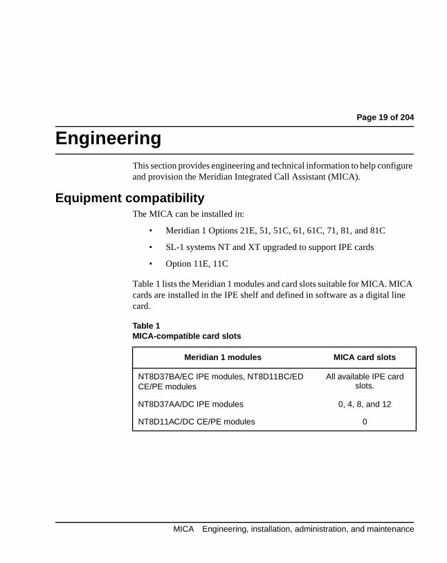
Table 1 lists the Meridian 1 modules and card slots suitable for MICA. MICcards are installed in the IPE shelf and defined in software as a digital licard.
MICA Engineering, installation, administration, and maintenance
Page 20 of 204 Engineering
her ply. ply for
d . This n
er to A
two led, he
Power RequirementsThe maximum number of MICA cards per IPE module is affected by all otcards located on the IPE shelf and their usage of the IPE 5V power supThe MICA uses a 3 Amp current from the 5V supply. The IPE power supprovides 28 Amp current. The IPE power supply provides 22 Amp currentthe Option 11.
The maximum IPE module per slot power budget is 30 Watts, with an effective limitation of 20 Watts for thermal compensation. The MICA cardoes not exceed the power allocated for each card slot in the IPE modulemeans there is no power limitation for the number of MICA cards you caplace in an IPE shelf.
Note: Power requirements limit the number of MICA cards in an Option 11 cabinet to six.
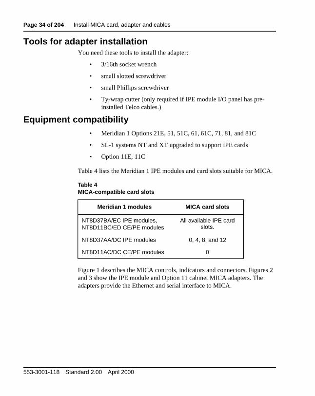
Card and adapter specificationsMICA electrical and environmental specifications are the identical to othsingle-slot IPE cards. The MICA faceplate provides two slots (A and B) hold the PCMCIA devices. Slot A must contain a PCMCIA device for MICto function. Slot B is reserved for another PCMCIA device, used during database backup and upgrades. MICA has one red card status LED andamber PCMCIA LEDs. The card status LED is ON when the card is disabOFF when card is enabled and blinks when MICA performs a self-test. TPCMCIA LEDs blink when the PCMCIA device is in use.
553-3001-118 Standard 2.00 April 2000
Engineering Page 21 of 204
tall
rnet
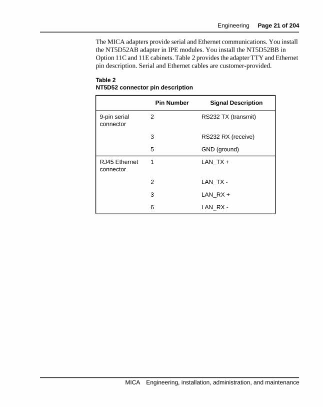
The MICA adapters provide serial and Ethernet communications. You insthe NT5D52AB adapter in IPE modules. You install the NT5D52BB in Option 11C and 11E cabinets. Table 2 provides the adapter TTY and Ethepin description. Serial and Ethernet cables are customer-provided.
Table 2NT5D52 connector pin description
Pin Number Signal Description
9-pin serial connector
2 RS232 TX (transmit)
3 RS232 RX (receive)
5 GND (ground)
RJ45 Ethernet connector
1 LAN_TX +
2 LAN_TX -
3 LAN_RX +
6 LAN_RX -
MICA Engineering, installation, administration, and maintenance
Page 22 of 204 Engineering
ce d
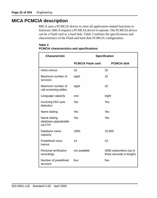
MICA PCMCIA descriptionMICA uses a PCMCIA device to store all application-related functions infirmware. MICA requires a PCMCIA device to operate. The PCMCIA devican be a Flash card or a hard disk. Table 3 outlines the specifications ancharacteristics of the Flash and hard disk PCMCIA configuration.
Table 3PCMCIA characteristics and specifications
Characteristic Specification
PCMCIA Flash card PCMCIA disk
Voice menus 16 32
Maximum number of services
eight 32
Maximum number of call screening tables
eight 32
Language capacity one eight
Incoming FAX auto detection
Yes Yes
Name dialing Yes Yes
Name dialing database upgradeable via FTP
Yes Yes
Database name capacity
1000 10,000
Predefined voice menus
14 22
Personal verification recordings
not available 3000 subscribers (up to three seconds in length)
Number of predefined services
four five
553-3001-118 Standard 2.00 April 2000
Engineering Page 23 of 204
ther
You
ith
o;
net ter.
iles) ing
ress
Network engineering recommendationsThis section describes the network components, cables, terminals and oinformation recommended to configure, administer and maintain MICA. Site-specific requirements may be different.
Serial network recommendationsYou enter MICA keycode and set IP address through a serial connection.can also use a serial connection for routine maintenance and system troubleshooting. The following items are required for MICA serial communications:
• 9-pin female serial cable. If you use a modem to communicate wMICA, you need a straight 9-pin to 25-pin cable, or a 9-pin cablewith a null modem.
• A TTY or computer with terminal emulation software. Use the following RS232 interface parameters:
• Transmission speed: 9600 bps; Data bits: 8; Stop bit: 1 Parity: NFlow control: none. Do not use XON/XOFF flow control.
Ethernet (TCP/IP) network recommendationsNortel Networks recommends that you configure the MICA card as a subof the LAN and connect the MICA to the corporate network through a rouTasks performed through the Ethernet TCP/IP connection include MICAOrganization, Administration and Maintenance (OA&M), routine card administration (firmware upgrade, and refreshing or replacing database fand maintenance and troubleshooting procedures. The items in the followlist are required for a MICA Ethernet connection:
• One RJ45 cable required per card for permanent connection
• One IP address for each MICA. Subnet mask and gateway addinformation can be identical for all MICAs on one subnet.
• Hub or router if required for connection to customer LAN
MICA Engineering, installation, administration, and maintenance
Page 24 of 204 Engineering
nt mer
nd
tly
on rsion
l
t
the
Application engineeringMICA supports two Auto Attendant application options. Auto-attendameans that MICA answers the incoming call and presents the custowith the option to dial-by-name, or dial by number to set up a call transfer. The two options are:
• Auto-attendant using circular hunt
• Auto-attendant using ACD features
Two ACD front-end call-handler application options are available. Afront-end call-handler application means that MICA answers the call athen presents menus that give customers multiple choices for call transfer, FAX, and other services. You can also handle calls differenroute depending on the incoming number.
• Call routing by menus only
• Call routing by dialed number.
Software engineeringThis section describes the X11 software package requirements for eachMICA configuration. The number of available ports on the MICA dependsthe software release installed in the Meridian 1. Install MICA in softwarereleases X11 Release 21 and up, X81-ph7c and up. If the software is veX11 Release 22 and up, MICA supports up to 32 ports. Earlier versions support a up to 16 ports.
MICA ports defined as ACD agents require ACD packages and ACD resources. Take the ACD resources into account in the ISM (IncrementaSoftware Management) customer configuration.
Customer definitions in Meridian 1 regarding the hunt feature apply if thecircular hunt configuration is used. The Pilot DN feature requires the PiloDN package, and Pilot DN operating parameters apply.
Activate the End-to-End Signalling feature to enable DTMF dialing from Meridian 1 proprietary sets. This applies even when the caller’s set is insame Meridian 1 switch as the MICA card.
553-3001-118 Standard 2.00 April 2000
Engineering Page 25 of 204
orts)
Software requirements for Auto-attendant usingcircular hunt
• Digital Set package 88 (Release 22 required for more than 16 p
• ESS - Enhanced End to End Signalling package 10
Software requirements for Auto-attendant usingACD features
• Digital Set package 88 (Release 22 for more than 16 ports)
• ESS - Enhanced End to End Signalling package 10
• ACD basic package 45
• ACD Advanced features package 41
Software requirements for ACD front-end Callrouting using menus
• Digital Set package 88 (Release 22 for more than 16 ports)
• ESS - Enhanced End-to-End Signaling package 10
• ACD basic package 45
• ACD advanced features package 41
Software requirements for ACD front-endcall routing using DNIS
• Digital Set package 88 (Release 22 for more than 16 ports)
• Enhanced End-to-End Signaling package 10
• ACD basic package 45
• ACD advanced features package 41
• DNIS package 98
MICA Engineering, installation, administration, and maintenance
Page 26 of 204 Engineering
ust 1 D
a DN r
Key
rts
.
ve
e
6\VWHP#UHVRXUFHVYou must consider the use of system ACD resources. If applicable, you mreview Incremental Software Management (ISM) for the specific Meridiansystem option. Each MICA card requires an ACD DN that defines the ACqueue; each MICA port represents an ACD agent that requires a TN and for Key 0 and a DN for Key 1. You can use a Multiple Appearance DN fothe Key 1 DN.
If you do not use ACD, then each MICA port represents a 2616 set that requires a TN and a DN for system resources used Key 0 and a DN for 1. You can use a Multiple Appearance DN for the Key 1 DN.
For example, a MICA card configured to the maximum capacity of 32 porequires the following system resources:
• 1 ACD DN assigned to the MICA card
• 32 TNs assigned to the 32 ports
Redundancy engineering rulesMICA redundancy requires the ACD configuration. You can define one MICA as a backup for another in the following manner:
• Define different ACD-DNs for the two MICAs.
• Define access numbers to the first ACD-DN, and define NCFW (Night Call Forward) on it to forward calls to the second ACD-DN
• Download identical databases to both MICA PCMCIA disks.
Multiple card engineering rulesYou can configure multiple MICAs to work together so that customers hamore ports serving the same service numbers in the following manner:
• On the Meridian 1 define different ACD-DNs for the MICAs.
• Define different trunks from the same DNIS trunk group to terminate on a different MICA ACD. Or define another ACD queuwith time overflow, distributing the calls between the different MICA ACDs, and have all trunks terminate on the Time OverflowACD.
• Download identical databases to each MICA PCMCIA disks.
553-3001-118 Standard 2.00 April 2000
Engineering Page 27 of 204
h
ce, ne
om ed it
the than
tion ber
e with e
ters, ngth
gits the
For more information, See “How to define a MICA service number” on page 31.
Personal verification recordings are not re-usable and must be made for eaccard. Define two different service DNs for recording purposes, with one leading to each MICA ACD-DN. The subscribers record their names twionce on each card. You can copy personal verification recordings from oMICA PCMCIA disk to another.
Configuration engineering rulesThe MICA administrator must know the language serial number in the customer’s set. It serves as the language ID for MICA Telephone User Interface (TUI) recording. The language serial number can be derived frthe BUI. In the Treatments window, when the list of languages is presentis in the order of the languages in the customer set.
The Database for name dialing is one table. It holds to 10,000 entries onhard disk and up to 1,000 in the Flash configuration. The database usesEnglish spelling only. If you have a name dialing database that has more10,000 names, MICA only uses the first 10,000.
Only subscribers with DNs of up to seven digits can record personal verifications. Three seconds is the maximum length of a personal verificarecording. In the hard-disk configuration, MICA supports personal subscrirecordings for up to 3000 subscribers. The Flash configuration does notsupport personal subscriber recordings.
If the caller selects name dialing and the input keys match more than onname, up to five names are announced. If there are more than five namesthe same keypad spelling, those subscribers cannot be reached by namdialing.
In the Name Dialing Database, the maximum length of name is 20 characincluding the space between the last and first name. The maximum DN lein this database is 20 digits.
In the Call Screening Table, the DN prefixes defined may be up to 20 diand there may be up to 100 entries in the table. The maximum length ofFAX DN is 20 digits.
MICA Engineering, installation, administration, and maintenance
Page 28 of 204 Engineering
n- lled for the
vice les, um
ing to a
d
s
use
o ic
Call transfer is subject to Meridian 1 limitations. For incoming calls on nosupervised trunks, Meridian 1 allows transfer completion only after the caparty has answered. In this case the MICA will continue retry the transferup to 15 seconds. During this time, the caller is on hold and will receive hold treatment defined in Meridian 1.
Customer may define up to 32 different service profiles (assigned to serDNs), which lead to 32 different menus and 32 different call screening tabbased on 16 different time types and 16 different CLID types, to a maximof 26 CLID digits.
Flash customer may define up to 8 different service profiles (assigned toservice DNs), which lead to 16 different menus and 8 different call screentables, based on 16 different time types and 16 different CLID types, up maximum of 26 CLID digits.
([WHUQDO#HTXLSPHQW#UHTXLUHPHQWVThere are three interfaces available to interact with the MICA:
• The Command Line Interface (CLI), for performing initial setup anconfiguration and performing upgrades
• The Browser User Interface (BUI), which uses a common web browser to create and manage services and treatments
• The Telephone User Interface (TUI), where you record greetingand menus
The following paragraphs describe the external equipment necessary toeach of these interfaces.
7R#DFFHVV#WKH#&/,A VT100 terminal or a personal computer emulating a terminal is used tperform MICA administration, configuration, maintenance, and diagnostfunctions through the CLI.
553-3001-118 Standard 2.00 April 2000
Engineering Page 29 of 204
32 d
e
d no l).
ess
s:
For initial setup and configuration, connect the terminal to the MICA RS-2interface or to the DB-9 connector on the NT5D52 Ethernet Adapter carinstalled on the I/O panel. For long-term administration and maintenance(through the CLI) telnet to the card over your LAN. Telneting requires thconnection of the MICA card to the LAN through the RJ45 jack on the Ethernet adapter.
The terminal interface must be set to 9600 baud, 8 data bits, 1 stop bit, anparity. The flow control is hard wired (never use XON/XOFF flow contro
7R#DFFHVV#WKH#%8,Access to the Browser User Interface (BUI) requires three things:
• a Local Area Network (LAN)
• a web server to house the BUI
• a web browser on a PC to access the BUI
/$1#FKDUDFWHULVWLFVEthernet implementation over the MICA has the following LAN characteristics:
The Ethernet adapter options for MICA are:
• NT5D52AB for the IPE module
• NT5D52BB for the Option 11E/11C
The LAN administrator assigns the IP address for the MICA. The IP addris entered over the VT100 terminal during initial setup.
The PC you use to access the BUI must have the following requirement
• minimum of 166 MHz PC Pentium processor
• minimum of 32 MB RAM
• minimum of 1 GB for the hard drive
MICA Engineering, installation, administration, and maintenance
Page 30 of 204 Engineering
ne of
ller .
us,
key
*
"call
the
Web browser characteristicsThe BUI operates from a Java 1.1 level. This requires the user to have othe following web browsers on his or her PC:
— Netscape 4.5 (or later)
— Internet Explorer 4.01 (or later) with Service Pack 1 (SP1)
About caller inputMICA accepts digit input while playing a greeting, so an experienced cacan immediately input the appropriate digit and reach the desired option
In the TUI, the * key can send users to the previous menu. In voice menthe default definition for the * key is to replay the previous menu.
For system menus, such as dial-by-name or dial-by-number, press the *to return to the main menu as long as the system prompt is playing.
If you have custom menus, you can define a customized function for thekey.
Callers who use dial-by-number can press the # key twice to bypass the is being transferred to" announcement.
Callers who use dial-by-name can press 1 after name dialing to skip theannouncement preceding the call transfer.
The # has specific meaning in name dialing and cannot be used to skip announcement.
553-3001-118 Standard 2.00 April 2000
Page 31 of 204
88
be y of
ard
ice. o a
and e.
the
How to define a MICA service numberThis section explains how to enter and define a service number.
You define service numbers on the Meridian 1 only for those numbers torouted to the MICA card, and only numbers that will appear on the displathe MICA units, so MICA can recognize the number.
If the service number uses ACD queues with their night DNs NCFW forwarding to a MICA ACD queue, then MICA requires a dedicated ACDqueue for each service and is Night Call Forwarded (NCFW) to the main cqueue.
You can forward your phone to a MICA queue and build a service in thebrowser for your phone. You do not have to build a queue for every servFor example, you can forward a 1-800 number of a four-digit extension tqueue.
There are two ways that MICA ports may be defined on the Meridian 1, each one has matching types of MICA service numbers that you can us
MICA ports defined as ACD agentsService numbers can be:
• ACD queues with no agents that have their night DN leading to MICA card DN. The MICA ACD DN itself cannot be used if the MICA is to distinguish it as a specific number. It can be used to reach the MICA and will receive the Default Service treatment.
• DNIS on an incoming route auto-terminating on the MICA card ACD queue.
MICA Engineering, installation, administration, and maintenance
Page 32 of 204 How to define a MICA service number
ICA
led
ll of
N/ (this
on.
Both kinds of service numbers can be used simultaneously on the same Mbut not on the same call. If a call is received with DNIS, the DNIS is considered the service number. Otherwise, the service number is the diaACD DN.
MICA ports defined as 2616 sets in a hunt circleIn this configuration, you use one service number to access the MICA. Acalls reach the default service. The number can be a pilot DN or the DNone of the MICA ports.
If you require multiple access DNs, you can define more than one pilot Dhunt group leading to the same ports. Or you can define a phantom looprequires the PHTN software package) with phantom TNs leading to the MICA hunt circle.
Do not use the port DNs for multiple DN access and service differentiati
You can forward any DN to MICA for Hunt and ACD options.
553-3001-118 Standard 2.00 April 2000
Page 33 of 204
88
ce
tall the to the in I/
Install MICA card, adapter and cablesIf you have never installed a Meridian 1 circuit card, read the EquipmentHandling Guidelines section in the Meridian 1 Installation and Maintenanmanual (365-3001-210).
Card and adapter descriptionThe MICA is a single-slot IPE card. It emulates a digital line card in Meridian 1. The MICA requires serial and Ethernet connections. You insan adapter with TTY and Ethernet ports to provide these connections. InIPE module, the adapter connects to the backplane cable that connects MICA card slot. In the Option 11 cabinet, the adapter plugs into the 50-pO connector in the cabinet.
Prepare for installation1 Select an IPE module card slot for MICA (see Table 4).
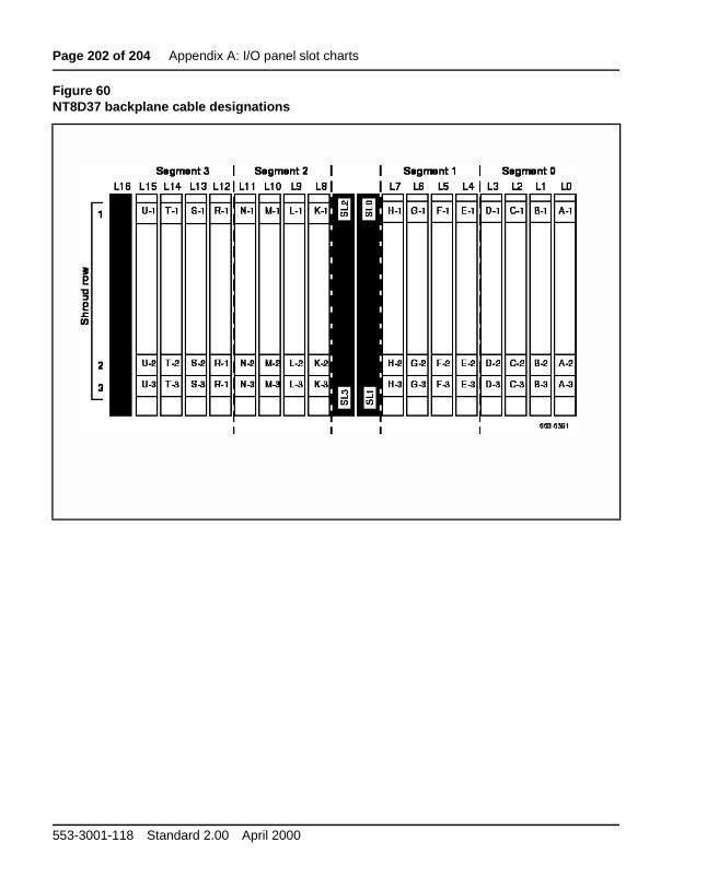
2 Locate the backplane I/O connector or cabinet connector for the slot. If you don’t know how to find the I/O connector for your module, See “I/O panel slot charts” on page 199.
3 Assemble tools.
4 Locate adapter.
5 Make sure module or cabinet has anti-static wrist strap, or attach anti-static shoe straps.
MICA Engineering, installation, administration, and maintenance
Page 34 of 204 Install MICA card, adapter and cables
A.
s 2
Tools for adapter installationYou need these tools to install the adapter:
• 3/16th socket wrench
• small slotted screwdriver
• small Phillips screwdriver
• Ty-wrap cutter (only required if IPE module I/O panel has pre-installed Telco cables.)
Equipment compatibility• Meridian 1 Options 21E, 51, 51C, 61, 61C, 71, 81, and 81C
• SL-1 systems NT and XT upgraded to support IPE cards
• Option 11E, 11C
Table 4 lists the Meridian 1 IPE modules and card slots suitable for MIC
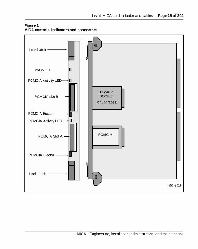
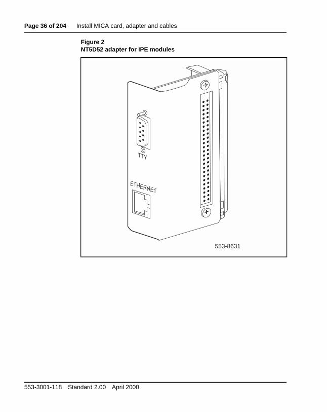
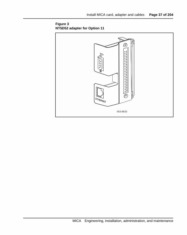
Figure 1 describes the MICA controls, indicators and connectors. Figureand 3 show the IPE module and Option 11 cabinet MICA adapters. The adapters provide the Ethernet and serial interface to MICA.
2 Attach anti-static wrist strap to your wrist or discharge static electricity on cabinet or module bare metal surface.
3 Select module or cabinet card slot according to work order or see Table 4.
4 Flip MICA top locking latch up and bottom locking latch down.
5 Insert MICA into card-aligning guides in card cage.
6 Gently push MICA into slot until you feel resistance.
7 Lock card in cardcage by simultaneously pushing ends of locking latches against faceplate.
8 If the module or cabinet is turned on, the MICA status LED and PCMCIA LED flash as MICA conducts a self-test. If self-test is successful, the PCMCIA LED goes out and the ENL/DIS LED remains ON until MICA is software-enabled in Overlay 32.
553-3001-118 Standard 2.00 April 2000
Install MICA card, adapter and cables Page 39 of 204
e
Install adapter in IPE module
1 Identify I/O panel connector that corresponds to MICA card slot.
2 Remove I/O panel safety cover.
3 Use 3/16th socket wrench and slotted screwdriver to disconnectfilter from I/O panel.
4 Pull filter and backplane cable through slot toward the backplane.
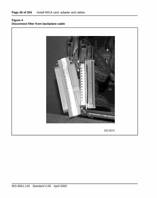
5 Unsnap the clips that connect filter to cable and discard filter (see Figure 4)
6 Use a small Phillips screwdriver to remove the two screws and washer from the adapter. Retain the screws and washers.
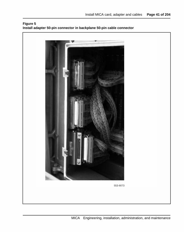
7 Plug adapter 50-pin connector into the backplane cable 50-pin connector. Press down on clips to snap adapter into place (see Figure 5).
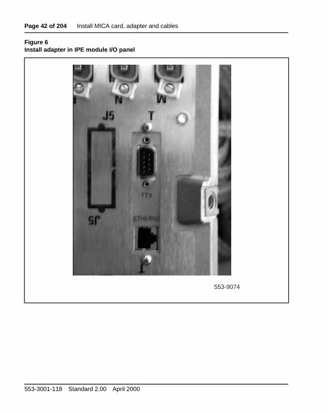
8 Position the adapter in the I/O panel slot, with the TTY adapter on top.
9 Attach the adapter to the I/O panel using the two small screws and washers (see Figure 6).
CAUTIONElectrical Shock Hazard
You remove the I/O safety panel to install the adapter. This can exposyou to high voltages (-48 Vdc) present in the IPE module backplane.
CAUTIONDo not drop fasteners into the Meridian 1 column. Loose metal hardware can cause serious power problems.
MICA Engineering, installation, administration, and maintenance
Page 40 of 204 Install MICA card, adapter and cables
Figure 4Disconnect filter from backplane cable
553-9075
553-3001-118 Standard 2.00 April 2000
Install MICA card, adapter and cables Page 41 of 204
Figure 5Install adapter 50-pin connector in backplane 50-pin cable connector
553-9073
MICA Engineering, installation, administration, and maintenance
Page 42 of 204 Install MICA card, adapter and cables
Figure 6Install adapter in IPE module I/O panel
553-9074
553-3001-118 Standard 2.00 April 2000
Install MICA card, adapter and cables Page 43 of 204
Install adapter in Option 11 cabinet1 Remove cabinet cover.
2 Remove I/O panel protective strip.
3 Select I/O connector corresponding to slot containing MICA.
4 Plug 50-pin side of adapter into I/O connector. Be sure port labeled TTY is facing you and is on top.
5 Replace I/O panel protective strip when you finish installing adapters.
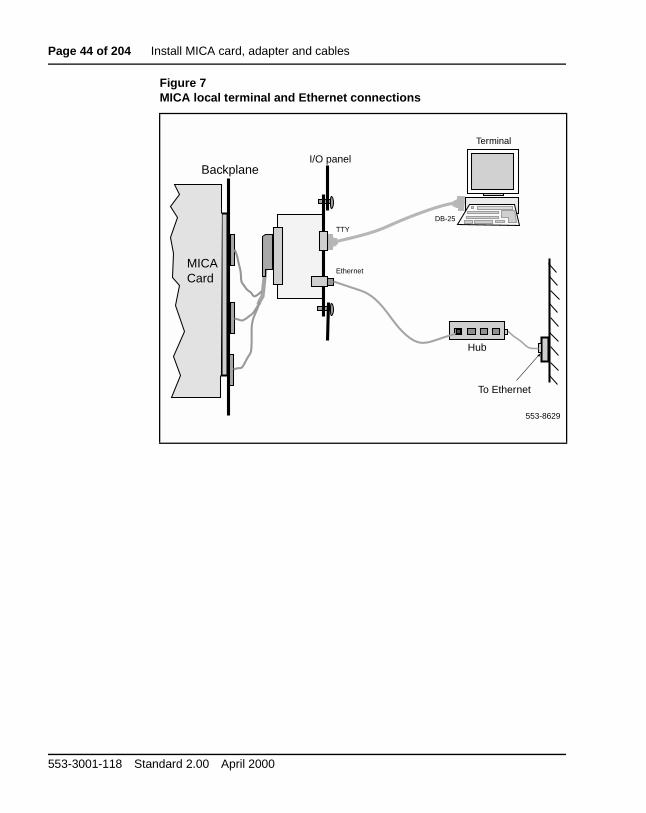
Connect local terminal and Ethernet cables to adapter1 Connect a DB9 to DB25 cable from adapter TTY port to terminal serial
port.
2 Configure the terminal or terminal emulation program settings:
• 9600 baud
• 8 data bits
• 1 stop bit
• no parity
MICA displays the key code prompt on the terminal screen as soon as you connect the terminal to the adapter.
3 Connect an RJ45 cable from the adapter Ethernet port to the Ethernet hub (see Figure 7.)
4 Connect MICA to your network using standard Ethernet connection rules.
MICA Engineering, installation, administration, and maintenance
Page 44 of 204 Install MICA card, adapter and cables
Figure 7MICA local terminal and Ethernet connections
I/O panel
Terminal
MICACard
Backplane
Hub
To Ethernet
553-8629
TTY
DB-25
Ethernet
553-3001-118 Standard 2.00 April 2000
Install MICA card, adapter and cables Page 45 of 204
and lish
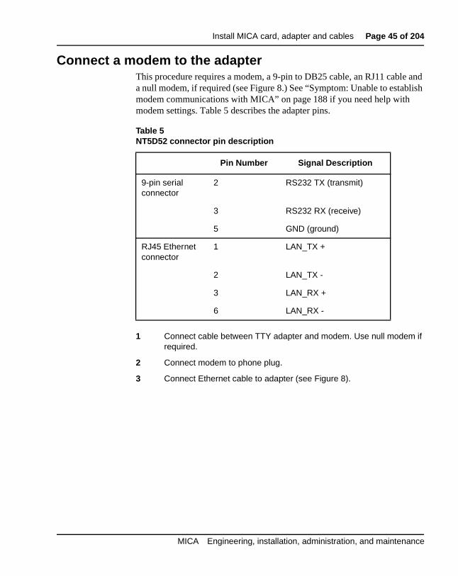
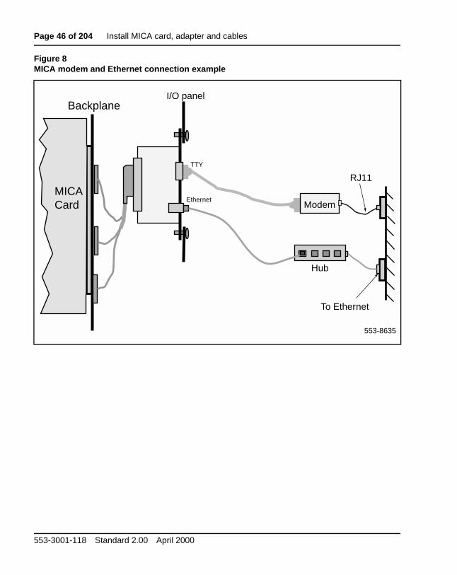
Connect a modem to the adapterThis procedure requires a modem, a 9-pin to DB25 cable, an RJ11 cablea null modem, if required (see Figure 8.) See “Symptom: Unable to estabmodem communications with MICA” on page 188 if you need help with modem settings. Table 5 describes the adapter pins.
1 Connect cable between TTY adapter and modem. Use null modem if required.
2 Connect modem to phone plug.
3 Connect Ethernet cable to adapter (see Figure 8).
Table 5NT5D52 connector pin description
Pin Number Signal Description
9-pin serial connector
2 RS232 TX (transmit)
3 RS232 RX (receive)
5 GND (ground)
RJ45 Ethernet connector
1 LAN_TX +
2 LAN_TX -
3 LAN_RX +
6 LAN_RX -
MICA Engineering, installation, administration, and maintenance
Page 46 of 204 Install MICA card, adapter and cables
Figure 8MICA modem and Ethernet connection example
I/O panel
MICACard
Backplane
Hub
To Ethernet
553-8635
Modem
TTY
Ethernet
RJ11
553-3001-118 Standard 2.00 April 2000
Page 47 of 204
88
r
e
32
Configure MICA initial settingsThis procedure explains how to:
• Enter the MICA keycode to activate the MICA ports
• Login to the Command Line Interface
• Enter IP address information
• Set ACD parameters, if required
MICA IP address, subnet mask and gateway address requirements
Obtain the following information for each MICA from your network manageor other source:
• IP address - is the MICA Internet Protocol address. It has the samformat as the gateway address.
• subnet mask - has XXX.XXX .XXX .XXX format, where every XXX is in the range 0-255. Subnet mask in binary presentation ofbits has at least the first eight digits “1” and the last digit is “0”.
• gateway address - has XXX.XXX.XXX.XXX format, where every token is in the range 0-255.
MICA Engineering, installation, administration, and maintenance
Page 48 of 204 Configure MICA initial settings
nd the
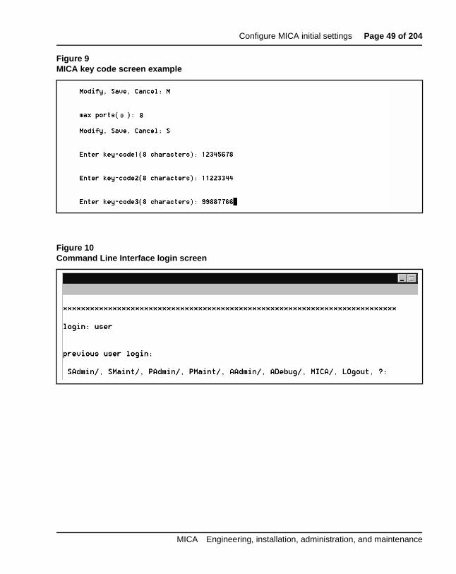
Enter the key code and loginMICA displays a key code prompt screen the first time you install MICA aconnect a terminal (see Figure 9). MICA requires a key code to activateports.
1 Establish a serial connection to MICA through the adapter TTY port. Set the terminal or computer terminal emulation program to the following parameters: Transmission speed: 9600 bps; Data bits: 8; Stop bit: 1 Parity: No; Flow control: none (Do not use XON/XOFF flow control).
2 Locate the key code label in the MICA shipping carton.
3 At the Modify, Save, Cancel: prompt, type M and press Return.
4 At the max ports(0): prompt, type in the number of MICA ports listed on the keycode label and press Return .
5 At the prompt Modify, Save, Cancel: prompt, type S and press Return.
6 Type in keycode1, then press Return. Type in keycode2, press Return. Type in keycode3, then press Return.
7 At the prompt Modify, Save, Cancel: prompt, type in S and press Return.
8 MICA continues the start-up process and displays the Command Line Interface (CLI) login screen (see Figure 10). At the login prompt, type user and press Return.
553-3001-118 Standard 2.00 April 2000
Configure MICA initial settings Page 49 of 204
Figure 9MICA key code screen example
Figure 10Command Line Interface login screen
MICA Engineering, installation, administration, and maintenance
Page 50 of 204 Configure MICA initial settings
he 11).
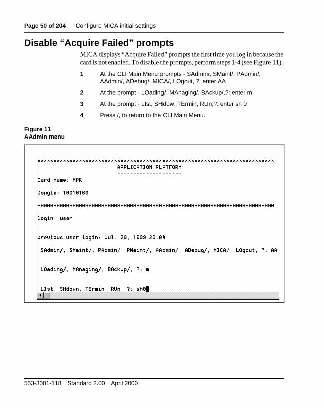
Disable “Acquire Failed” promptsMICA displays “Acquire Failed” prompts the first time you log in because tcard is not enabled. To disable the prompts, perform steps 1-4 (see Figure
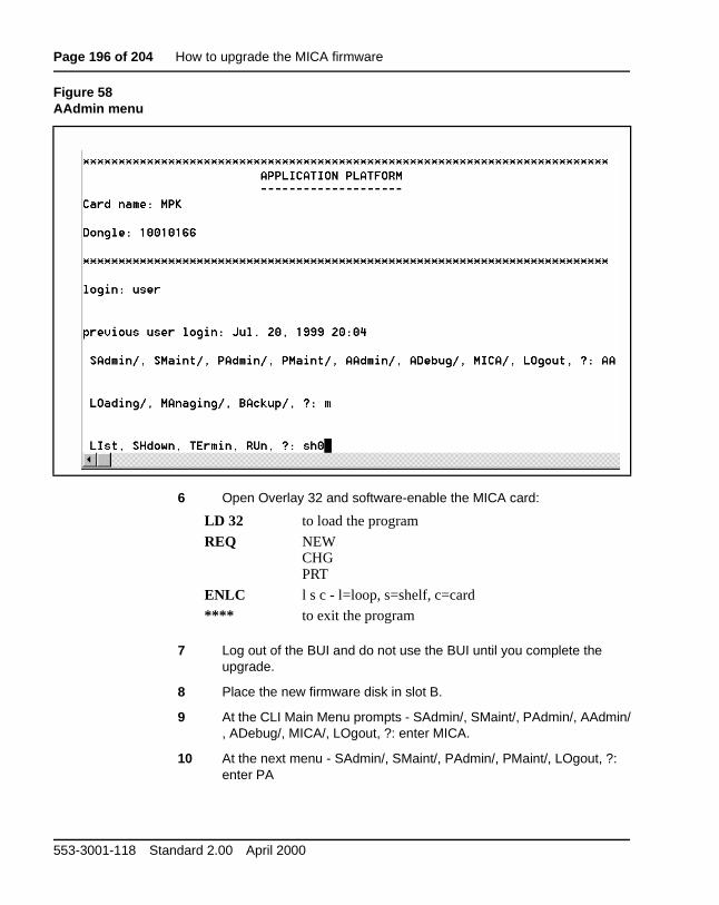
1 At the CLI Main Menu prompts - SAdmin/, SMaint/, PAdmin/, AAdmin/, ADebug/, MICA/, LOgout, ?: enter AA
2 At the prompt - LOading/, MAnaging/, BAckup/,?: enter m
3 At the prompt - LIst, SHdow, TErmin, RUn,?: enter sh 0
4 Press /, to return to the CLI Main Menu.
Figure 11AAdmin menu
553-3001-118 Standard 2.00 April 2000
Configure MICA initial settings Page 51 of 204
Enter IP address for non-ACD configuration1 At the CLI Main Menu prompt (see Figure 12):
D VHOHFW#0,&$#DQG#SUHVV#5HWXUQ
E 6HOHFW#6$#DQG#SUHVV#5HWXUQ
F 6HOHFW#6<#DQG#SUHVV#5HWXUQ
2 At the prompt card name: enter up to ten characters to change the default card name for MICA, if required.
3 At the prompt subnet mask: enter the subnet mask data.
4 At the prompt gateway address: enter the gateway address.
5 At the prompt IP address: enter the IP address.
6 At the prompt Modify, Save, Cancel: type S and press Return.
7 At the prompt Restart AP? (Yes, (No)) type Y.
8 The MICA automatically restarts
Figure 12Enter IP address - non-ACD configuration
MICA Engineering, installation, administration, and maintenance
Page 52 of 204 Configure MICA initial settings
ee
ted
g is
nt s
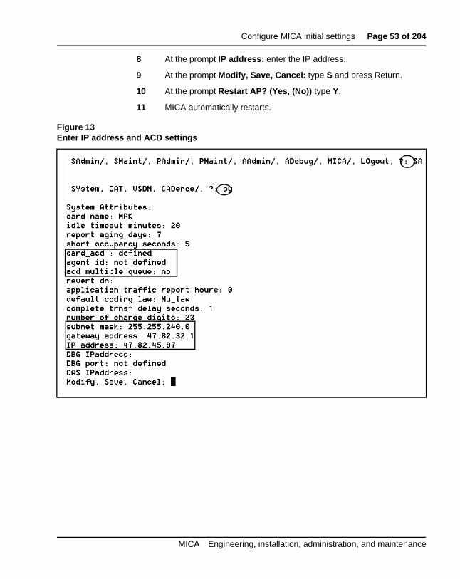
Enter IP address and ACD settings for ACD configurationIn this procedure, you select SA/SY directory from the CLI main menu (scircled items in Figure 13). MICA presents a window that contains 18 prompts. You only respond to the prompts listed below, which are highlighby a square box in Figure 13:
• card name (change card name if desired)
• card_acd: Press return to set ACD definitions. The default settinY.
• Agent ID: if you use Agent ID, enter the first number of the AgeID. For example, if you have a group of 32 agent IDs that beginwith 2000, enter 2000
• Multiple queue: Enter a Y or N
• subnet mask:
• gateway address:
• IP address:
IP address and ACD settings procedures
1 Login to MICA. At the main menu prompt (refer to Figure 13 on page 51):
D VHOHFW#6$#DQG#SUHVV#5HWXUQ
E 6HOHFW#6<#DQG#SUHVV#5HWXUQ
2 At the prompt card name: enter up to ten characters to change the default card name for MICA, if required.
Press Return until you reach card_acd
3 At the prompt card_acd: press Return if you use ACD, or enter N if you use Hunt.
4 At the prompt agent ID: enter the first number of the Agent ID group
5 At the prompt acd multiple queue: enter Y or N.
Press Return until you reach subnet mask.
6 At the prompt subnet mask: enter the subnet mask data.
7 At the prompt gateway address: enter the gateway address.
553-3001-118 Standard 2.00 April 2000
Configure MICA initial settings Page 53 of 204
8 At the prompt IP address: enter the IP address.
9 At the prompt Modify, Save, Cancel: type S and press Return.
10 At the prompt Restart AP? (Yes, (No)) type Y.
11 MICA automatically restarts.
Figure 13Enter IP address and ACD settings
MICA Engineering, installation, administration, and maintenance
Page 54 of 204 Configure MICA initial settings
553-3001-118 Standard 2.00 April 2000
Page 55 of 204
88
se
nt mer
nd
tly
Prepare to configure MICAIn this section, you learn how to prepare for MICA configuration. You configure MICA in two steps:
Step 1 - Build phone sets in LD11, build the ACD queue in LD23 (if you uthe ACD applications) and software-enable MICA in LD32.
Step 2 - Login to the MICA Browser User Interface (BUI) and build treatments for MICA service(s). A MICA treatment contains a set of instructions that tell MICA how to handle a call to a MICA service DN.
Preparation tasks1 Select a MICA application
MICA supports two Auto Attendant application options. Auto-attendameans that MICA answers the incoming call and presents the custowith the option to dial-by-name, or dial by number to set up a call transfer. The two options are:
• Auto-attendant using circular hunt
• Auto-attendant using ACD features
Two ACD front-end call-handler application options are available. Afront-end call-handler application means that MICA answers the call athen presents menus that give customers multiple choices for call transfer, FAX, and other services. You can also handle calls differenroute depending on the incoming number.
• Call routing by menus only
• Call routing by dialed number.
MICA Engineering, installation, administration, and maintenance
Page 56 of 204 Prepare to configure MICA
of
e rts of
ed gin.
ot
rs,
N
DN
2 Verify that you have the required software packages to support yourMICA application. See “Software engineering” on page 24.
3 If you use Agent ID, get a block of sequential Agent IDs. The quantityAgent IDs equals the amount of MICA ports.
4 If you use ACD scheduled data blocks, then the agent IDs must be consecutive numbers within the lower and upper limit starting with thnumber assigned to the first agent ID. If you use Agent ID, MICA podo not login until you enter ACD definitions in the Properties window the Browser User Interface.
5 If you use ADS or SCB, the maximum number of agents who are allowto login at once must also be adjusted to allow the MICA agents to loThis is done in the LOG prompt in the SCB or ADS block.
6 Find out if you use Multiple Queue Assignments (MQA).
7 Decide if you will use the RPRT in LD23. You cannot change these settings once you build your phones. If the RPRT is set to NO, it is nnecessary to set MQA on MICA to YES.
Configuration guidelines1 Define the ACD block. The administrator can define RAN routes, time
overflow and other attributes.
2 Define access DNs:
• ACD queues with no agents, their night DN leading to the ACD Ddefined in the first step, or
• Define an incoming route with DNIS, and its trunks auto-terminating on ACD defined in the first step.
3 Define each unit of the card as a digital set (2616), agent of the ACD defined in the first step. Define keys as:
• Key 0 - ACD
• Key 1 - SCN (Single Call Not-Ringing) with a dedicated DN.
• Key 2 - NRD (Not Ready)
• Key 3 - MSB (Make Set Busy)
• Key 4 - TRN (Transfer)
553-3001-118 Standard 2.00 April 2000
Prepare to configure MICA Page 57 of 204
s nits
4 Consider that MICA handles call transfer screening when you defineaccess restrictions.
5 If only a subset of the card’s units are configured, they should alwaybegin from unit 0 and on. In release 22 and up, you can configure u17-31 as voice units.
6 After defining all ports, enable the card.
MICA Engineering, installation, administration, and maintenance
Page 58 of 204 Prepare to configure MICA
553-3001-118 Standard 2.00 April 2000
Page 59 of 204
88
nd ts
e
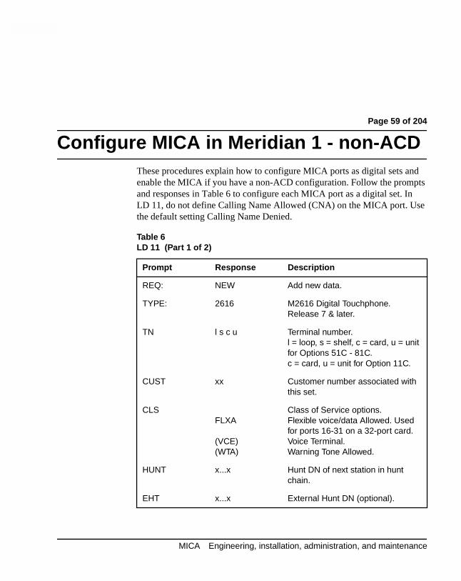
Configure MICA in Meridian 1 - non-ACDThese procedures explain how to configure MICA ports as digital sets aenable the MICA if you have a non-ACD configuration. Follow the prompand responses in Table 6 to configure each MICA port as a digital set. InLD 11, do not define Calling Name Allowed (CNA) on the MICA port. Usthe default setting Calling Name Denied.
Table 6LD 11 (Part 1 of 2)
Prompt Response Description
REQ: NEW Add new data.
TYPE: 2616 M2616 Digital Touchphone. Release 7 & later.
TN l s c u Terminal number.l = loop, s = shelf, c = card, u = unit for Options 51C - 81C.c = card, u = unit for Option 11C.
CUST xx Customer number associated with this set.
CLSFLXA
(VCE)(WTA)
Class of Service options.Flexible voice/data Allowed. Used for ports 16-31 on a 32-port card.Voice Terminal.Warning Tone Allowed.
HUNT x...x Hunt DN of next station in hunt chain.
EHT x...x External Hunt DN (optional).
MICA Engineering, installation, administration, and maintenance
Page 60 of 204 Configure MICA in Meridian 1 - non-ACD
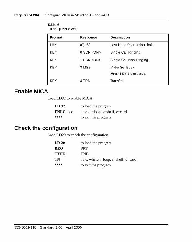
Enable MICALoad LD32 to enable MICA:
Check the configurationLoad LD20 to check the configuration.
LHK (0) -69 Last Hunt Key number limit.
KEY 0 SCR <DN> Single Call Ringing.
KEY 1 SCN <DN> Single Call Non-Ringing.
KEY 3 MSB Make Set Busy.
Note: KEY 2 is not used.
KEY 4 TRN Transfer.
LD 32 to load the program
ENLC l s c l s c - l=loop, s=shelf, c=card
**** to exit the program
LD 20 to load the program
REQ PRT
TYPE TNB
TN l s c, where l=loop, s=shelf, c=card
**** to exit the program
Table 6LD 11 (Part 2 of 2)
Prompt Response Description
553-3001-118 Standard 2.00 April 2000
Page 61 of 204
88
nts
re
or ents
se
Configure MICA in Meridian 1 - using ACDThese procedures explain how to build an ACD queue, build the ACD ageand enable the MICA.
Note: Be sure to read “Prepare to configure MICA” on page 55 befoyou configure the ACD queue and agents.
You define Agent ID and other parameters in the Browser User Interfacethe Command Line Interface. You must define the settings or the ACD agcannot log in.
Determine sequential Agent ID numbers, MQA settings
If your application uses Agent ID, perform steps 1 and 2. If you do not uAgent ID, start with step 2.
1 If your application uses Agent ID, determine a new range of sequential four-digit Agent ID numbers for MICA. You may use CPND for queues forwarded to the MICA queue. The quantity of Agent IDs required depends on the number of MICA ports you purchased. The number of ports is printed on the keycode label. For example, if you have an 8-port MICA, you need eight sequential four-digit Agent ID numbers.
2 If you use MQA, do not define Calling Party Name Display (CPND) for the ACD queue used for MICA. If you do not use MQA, you can use CPND. Use Overlay 23 to find out the Agent ID range that exists and to find out the Multiple Queue Agent (MQA) settings (MQA=yes or MQA=no):
MICA Engineering, installation, administration, and maintenance
Page 62 of 204 Configure MICA in Meridian 1 - using ACD
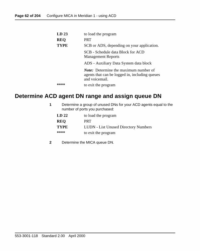
Determine ACD agent DN range and assign queue DN1 Determine a group of unused DNs for your ACD agents equal to the
number of ports you purchased:
2 Determine the MICA queue DN.
LD 23 to load the program
REQ PRT
TYPE SCB or ADS, depending on your application.
SCB - Schedule data Block for ACD Management Reports
ADS - Auxiliary Data System data block
Note: Determine the maximum number of agents that can be logged in, including queues and voicemail.
**** to exit the program
LD 22 to load the program
REQ PRT
TYPE LUDN - List Unused Directory Numbers
**** to exit the program
553-3001-118 Standard 2.00 April 2000
Configure MICA in Meridian 1 - using ACD Page 63 of 204
Build an ACD queue in LD231 Open Overlay 23.
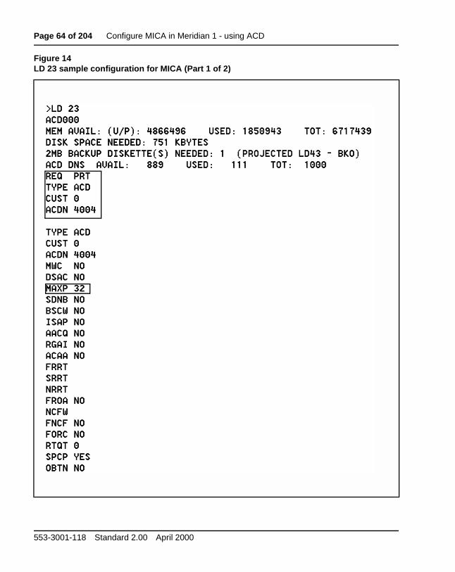
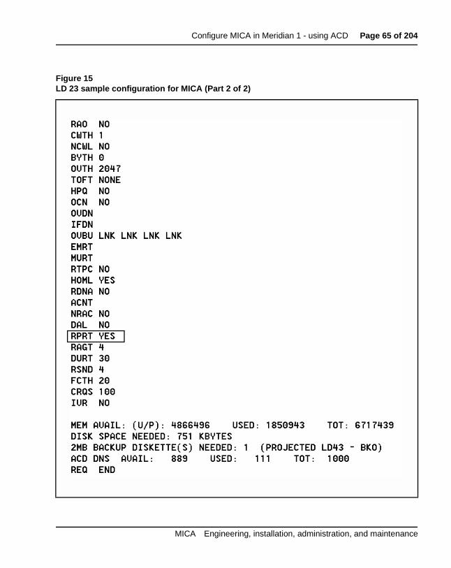
2 Build the ACD queue for MICA. Figures 14 and 15 show an example of an ACD queue programmed in LD23. The prompts and responses are highlighted with a black square.
Table 7LD 23 Build an ACD queue
Prompt Response Description
REQ NEWCHGPRT
Add new dataChange existing dataPrint data.
TYPE ACD Automatic Call Distribution
CUST xx Customer number associated with this data block.
ACDN x...x ACD Directory Number assigned to the MICA card. This is the ACD queue DN.Up to four digits, up to seven digits with Directory Number Expansion (DNXP) package 150.
MAXP xx
1-5001-10001-1200
Maximum Number of AgentPositions. This number equals the maximum available ports on MICA. MAXP value can be increased to the allowed maximum or decreased to the current agents.
For NT and Options 51 and 61For XTFor Option 71 and 81.
RPRT (YES) NO Management reporting and status display.
MICA Engineering, installation, administration, and maintenance
Page 64 of 204 Configure MICA in Meridian 1 - using ACD
Figure 14LD 23 sample configuration for MICA (Part 1 of 2)
553-3001-118 Standard 2.00 April 2000
Configure MICA in Meridian 1 - using ACD Page 65 of 204
Figure 15LD 23 sample configuration for MICA (Part 2 of 2)
MICA Engineering, installation, administration, and maintenance
Page 66 of 204 Configure MICA in Meridian 1 - using ACD
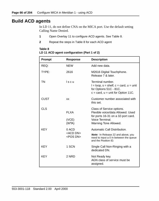
Build ACD agentsIn LD 11, do not define CNA on the MICA port. Use the default setting Calling Name Denied.
1 Open Overlay 11 to configure ACD agents. See Table 8.
2 Repeat the steps in Table 8 for each ACD agent
Table 8LD 11 ACD agent configuration (Part 1 of 2)
Prompt Response Description
REQ: NEW Add new data.
TYPE: 2616 M2616 Digital Touchphone. Release 7 & later.
TN l s c u Terminal number.l = loop, s = shelf, c = card, u = unit for Options 51C - 81C.c = card, u = unit for Option 11C.
CUST xx Customer number associated with this set.
CLSFLXA
(VCE)(WTA)
Class of Service options.Flexible voice/data Allowed. Used for ports 16-31 on a 32-port card.Voice Terminal.Warning Tone Allowed.
KEY 0 ACD<ACD DN><POS DN>
Automatic Call Distribution.
Note: In Release 22 and above, you need to input a 0 in between the queue and the Position ID.
KEY 1 SCN Single Call Non-Ringing with a dedicated DN.
KEY 2 NRD Not Ready key.AGN class of service must be assigned.
553-3001-118 Standard 2.00 April 2000
Configure MICA in Meridian 1 - using ACD Page 67 of 204
ow
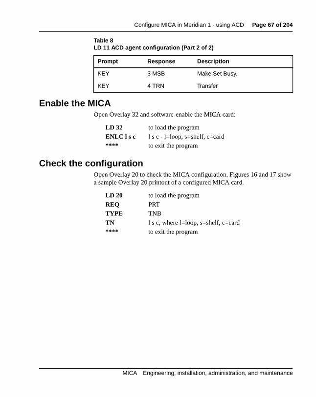
Enable the MICAOpen Overlay 32 and software-enable the MICA card:
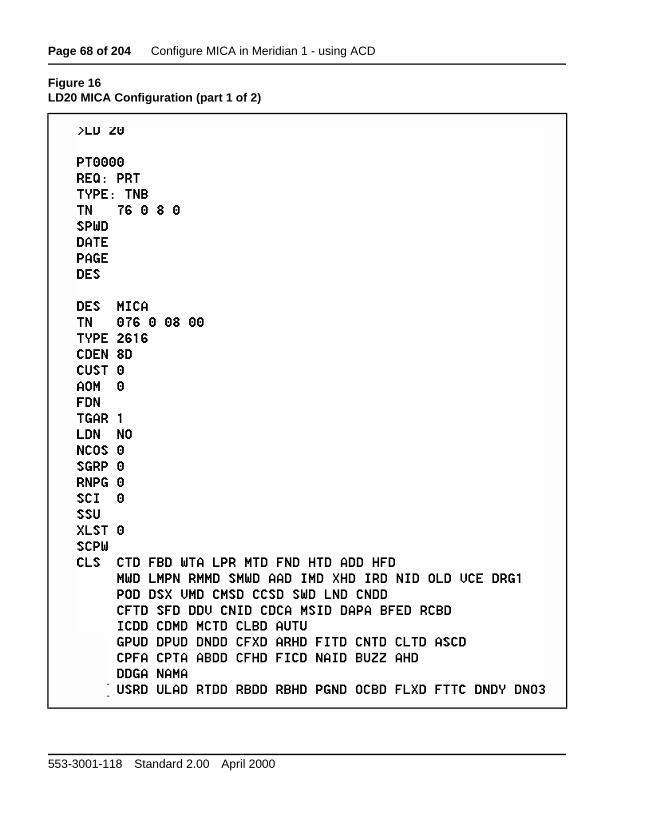
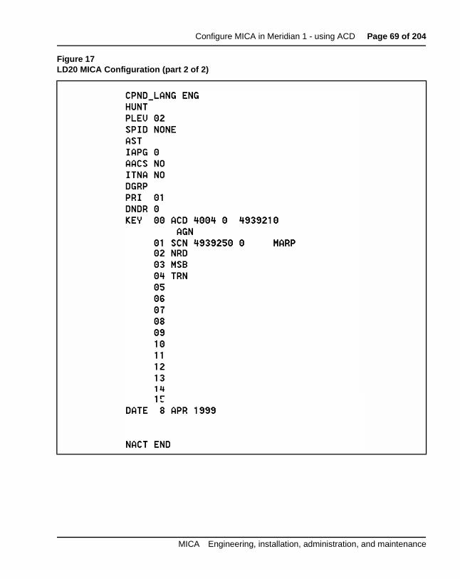
Check the configurationOpen Overlay 20 to check the MICA configuration. Figures 16 and 17 sha sample Overlay 20 printout of a configured MICA card.
KEY 3 MSB Make Set Busy.
KEY 4 TRN Transfer
LD 32 to load the program
ENLC l s c l s c - l=loop, s=shelf, c=card
**** to exit the program
LD 20 to load the program
REQ PRT
TYPE TNB
TN l s c, where l=loop, s=shelf, c=card
**** to exit the program
Table 8LD 11 ACD agent configuration (Part 2 of 2)
Prompt Response Description
MICA Engineering, installation, administration, and maintenance
Page 68 of 204 Configure MICA in Meridian 1 - using ACD
Figure 16LD20 MICA Configuration (part 1 of 2)
553-3001-118 Standard 2.00 April 2000
Configure MICA in Meridian 1 - using ACD Page 69 of 204
Figure 17LD20 MICA Configuration (part 2 of 2)
MICA Engineering, installation, administration, and maintenance
Page 70 of 204 Configure MICA in Meridian 1 - using ACD
553-3001-118 Standard 2.00 April 2000
Page 71 of 204
88
utes
ing n off the ICA:
rvice u tial
MICA application examplesThis section gives examples of three MICA applications.
Example 1 - An ACD menu-driven applicationIn Example 1, MICA is installed at City Power, a utility company. MICA answers calls with a customized greeting, plays menus to callers and rocalls depending on keypad digits entered by customers.
City Power Inc. provides a single phone number for sales, service, incomfaxes and emergencies. A customer finds that an AC power line has fallea pole during a storm and is live and sparking in her back yard. She callscompany at 1(800) 234-1000 and is greeted by an announcement from M
“Welcome to City Power.
For Sales press 1
For a Service Emergency press 2
For normal Service press 3
For name dialing press 4
If you know the extension number press 5
When the customer presses 2, MICA routes the call to an emergency setechnician. When the customer selects “1” for Sales, MICA plays a menscript telling customers to press 1 for commercial sales and 2 for residensales. Then they are placed into an ACD queue.
MICA Engineering, installation, administration, and maintenance
Page 72 of 204 MICA application examples
uto- on .
r as ) is
.
s ) is 2-
ld
aner one
ge:
.
Example 2 - ACD front-end call handler using DNISIn these ACD call center scenarios, all incoming call center trunks are aterminated to one or more MICAs, depending on the number of incomingtrunks. MICA plays specific greetings and menus and routes calls basedinformation provided by the Dialed Number Identification Service (DNIS)
Customer A calls 1-800-555-2000 to buy a Moore Super Vacuum Cleaneadvertised on television. The trunk they are terminated on (route 1 unit 3auto-terminated to a MICA port. MICA sees the incoming DNIS 1-(800)-555-2000 and plays a special message:
“Thank you for calling the Moore Super Vacuum Cleaner order deskPlease hold for the next available operator”
The call is then placed into an ACD queue.
Customer B calls 1-800-222-3000 to buy a pair of Moore Super Boots aadvertised on television. The trunk they are terminated on (route 1 unit 3auto-terminated to a MICA port. MICA sees the incoming DNIS (800) 223000 and plays a special message:
“Thank you for calling the Moore Super Boots order desk. Please hoon to order your new boots.”
The call is then placed into an ACD queue.
Example 3 - ACD front-end call handler using DNIS and CLID
Customer A in Quebec, Canada wants to buy a Moore Super Vacuum Cleas advertised on television. She calls 1-800-555-2000 from her home ph(514) 321-1234. The trunk she is terminated on (route 1 unit 3) is auto-terminated to a MICA port. MICA sees the incoming CLID of (514) 555-1234 and the DNIS 1-(800)-555-2000 and plays a special French messa
“Thank you for calling the Moore Super Vacuum Cleaner order deskPlease hold for the next available operator”
The call is then placed into an ACD queue. MICA transmits CLID information so the call is answered in French.
553-3001-118 Standard 2.00 April 2000
MICA application examples Page 73 of 204
aner ne -
.
Customer B in Toronto, Canada wants to buy a Moore Super Vacuum Cleas advertised on television. He calls 1-800-555-2000 from his home pho(416) 321-1234. The trunk they are terminated on (route 1 unit 3) is autoterminated to a MICA port. MICA sees the incoming CLID of (514) 555-1234 and the DNIS 1-(800)-555-2000 and plays an English message:
“Thank you for calling the Moore Super Vacuum Cleaner order deskPlease hold for the next available operator”
The call is then placed into an ACD queue. MICA transfers the call to anEnglish speaking agent. MICA transmits CLID information so the call is answered in English.
MICA Engineering, installation, administration, and maintenance
Page 74 of 204 MICA application examples
553-3001-118 Standard 2.00 April 2000
Page 75 of 204
88
et
f
.
and
BUI configuration summaryThe MICA Browser User Interface (BUI) is a Web server installed on theMICA PCMCIA. You access the BUI using Netscape or Microsoft InternExplorer.
You configure the MICA BUI in three steps:
1 Set Properties and Special Days (usually done once during initial MICA installation and configuration).
2 Create services and assign treatments that tell MICA how to handle incoming calls to the services.
3 Import, create or modify a name dialing database.
Properties procedure summaryLogin to MICA, click the Properties tab and configure four types of properties:
• General: Settings in this tab include Time-out periods, the number odialed digits allowed in a valid DN, enabling Personal Recorded messages for all users and setting the Voice Mail, Operator.
• Administration: Includes Interface Passwords, and login window title
• Card: Displays the card's identity and version, and allows you to setACD-related data.
• Reports: Determine which statistical reports to collect for MICA and how long to keep the reports.
Special days procedure summaryLogin to MICA, click the Special Days tab and configure Holidays, Vacations and any Special Day as required. You also define WeekdaysHolidays.
MICA Engineering, installation, administration, and maintenance
Page 76 of 204 BUI configuration summary
Service configuration procedure summaryWhen you configure a service, you define the parameters MICA uses tohandle customer calls.
Name dialing database procedure summaryYou use Name Dialing tab in the BUI to:
• import a name dialing database
• create a name dialing database
• edit a name dialing database
553-3001-118 Standard 2.00 April 2000
Page 77 of 204
88
ce
s:
ne of
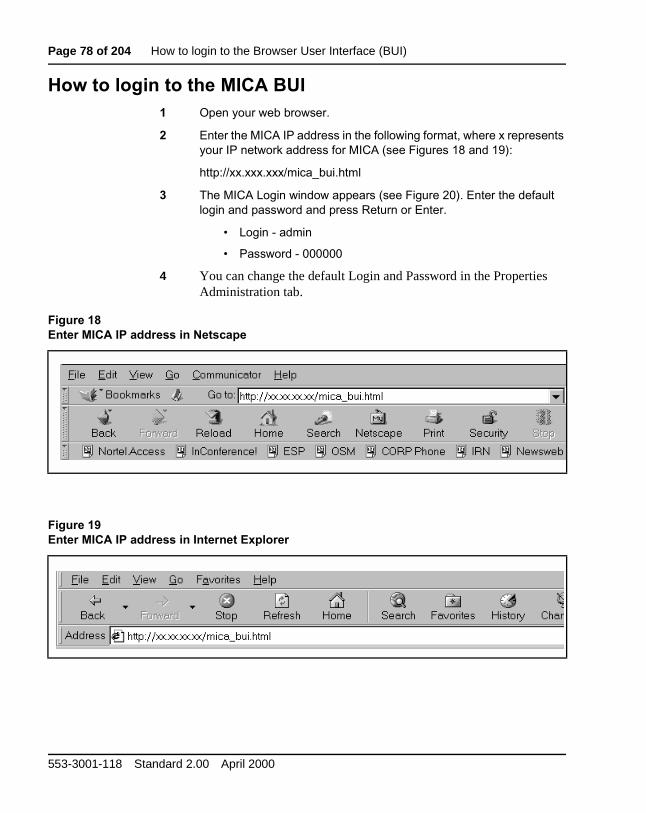
How to login to the Browser User Interface (BUI)
These procedures explain how to login to the MICA Browser User Interfa(BUI).
PC requirementsThe PC you use to access the BUI must have the following requirement
• minimum of 166 MHz PC Pentium processor
• minimum of 32 MB RAM
• minimum of 1 GB for the hard drive
Web browser characteristicsThe BUI operates from a Java 1.1 level. This requires the user to have othe following web browsers on his or her PC:
• Netscape 4.5 (or later)
• Internet Explorer 4.01 (or later)
MICA Engineering, installation, administration, and maintenance
Page 78 of 204 How to login to the Browser User Interface (BUI)
How to login to the Browser User Interface (BUI) Page 79 of 204
)LJXUH#530,&$#/RJLQ#ZLQGRZ
MICA Engineering, installation, administration, and maintenance
Page 80 of 204 How to login to the Browser User Interface (BUI)
553-3001-118 Standard 2.00 April 2000
Page 81 of 204
88
al
er ed
set
d
Define Properties and Special DaysThese procedures explain how to set MICA properties and define SpeciDays.
Define Properties In this step, you set four MICA card properties:
• General: Settings in this tab include Time-out periods, the numbof dialed digits allowed in a valid DN, enabling Personal Recordmessages for all users and setting the Voice Mail, Operator.
• Administration: Includes Interface Passwords, and login windowtitle.
• Card: Displays the card's identity and version, and allows you toACD-related data.
• Reports: Determine which statistical reports to collect for MICA anhow long to keep those reports.
Note: Set the Properties in all four windows and then press OK.
MICA Engineering, installation, administration, and maintenance
Page 82 of 204 Define Properties and Special Days
Configure the General Properties window
1 Login to MICA.
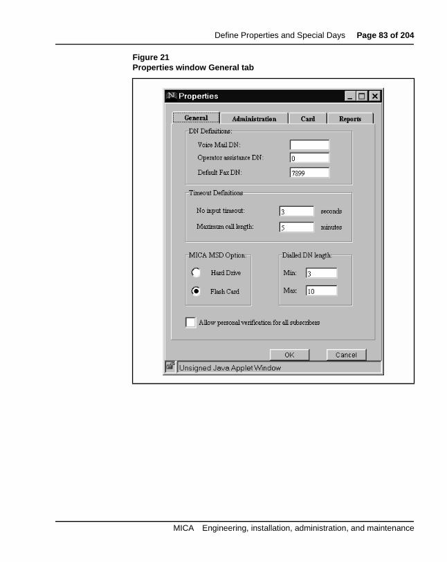
2 From the Main window, press the Properties button. The Properties window General tab appears. See Figure 21.
3 Set the MICA card DN definitions for Voice Mail, Operator Assistance and Default FAX. These settings define transfer destinations for received calls. DN transfer destinations are left empty, if they are not assigned. Enter up to 20 digits
4 Set Timeout Definitions . Maximum call length defines the time period before the call receives the Timeout Action defined for Call duration in the Voice Menus Options tab. Range is 1-20 minutes.
No input time-out defines the time period that the system waits for caller input before it takes the preset Timeout Action defined for No action in the Voice Menus Options tab. Range is one-ten seconds. MICA also recognizes this setting as the length of time used as interdigit timeout for name and number dialing.
5 Set Dialed DN length parameters to set the number of digits allowed in a valid DN when the caller uses dial-by-number. This can provide an additional security check. DNs with fewer than the defined minimum or exceeding the defined maximum number of digits are disqualified. DN digit range is 1-32.
6 Allow or deny Personal Verification for all subscribers. Clicking on this dialog box displays a check mark and sets the Personal Recording option for all users. If this global option is not checked, Personal Recording must be Allowed or Denied to each user in the Name Dialing Database displayed on the Name Dialing Edit window. If you have a database with more than 3,000 names, do not click this box. The Flash configuration maximum database size is 1,000 names.
553-3001-118 Standard 2.00 April 2000
Define Properties and Special Days Page 83 of 204
Figure 21Properties window General tab
MICA Engineering, installation, administration, and maintenance
Page 84 of 204 Define Properties and Special Days
Set Administration Properties
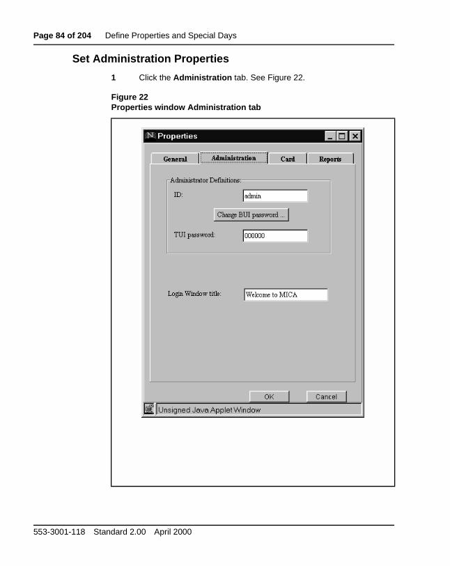
1 Click the Administration tab. See Figure 22.
Figure 22Properties window Administration tab
553-3001-118 Standard 2.00 April 2000
Define Properties and Special Days Page 85 of 204
Set Card Properties
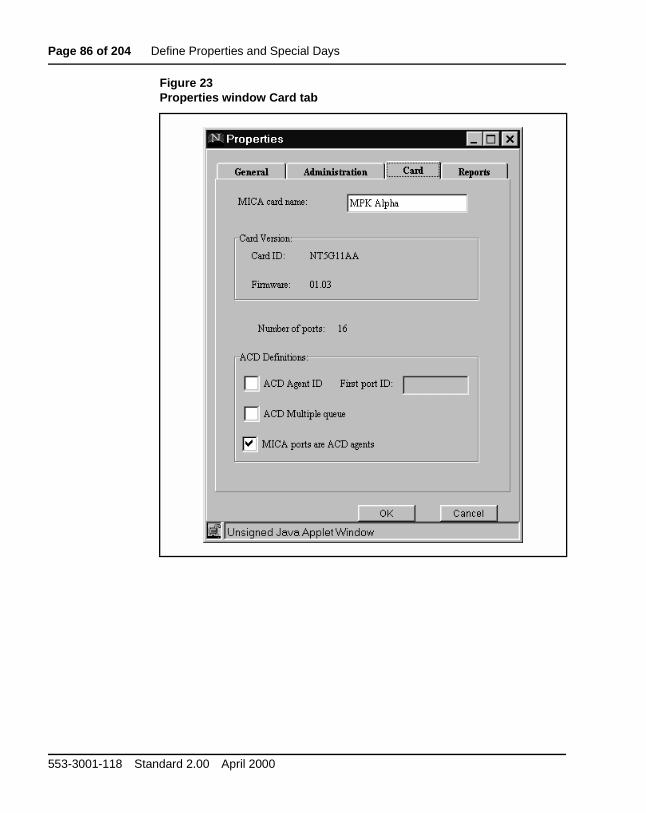
1 Click on the Card tab. See Figure 23.
2 Set Administrator Definitions
— ID - Defines login ID of the BUI user. Enter up to 20 characters and/or digits. The default is set to admin.
— Change BUI password - Press this button to open the Password Change dialog box. Enter up to six characters and/or digits to replace the default password of six zeros (000000).
— Change TUI password Enter up to six digits to replace the default digit string 000000.
3 If required, change the default MICA card name. Enter up to 20 characters and/or digits. The new card name is displayed in the main window's title the next time you login to MICA.
4 Card version information is for viewing only and cannot be changed.
5 If you did not set ACD parameters in the CLI, set ACD parameters in this step. The ACD parameters are for ACD setup, and must match the configuration in Meridian 1.
Note: If you make and save changes to ACD settings in the BUI, the CLI reflects the changes.
— Agent ID - Click in the box if your ACD is configured with agent-ID option. The 'First port ID' box turns white. Enter the first agent ID reserved for MICA ports (length is four digits). This field corresponds to the agent ID prompt in the CLI.
— ACD multiple queue - should be selected if customer's ACD is configured with multiple-queue option. This field corresponds to the acd multiple queue: prompt in the CLI.
— MICA ports are ACD agents - indicates whether MICA ports are defined in Meridian 1 as ACD agents or plain 2616 sets. This field corresponds to the card_acd: prompt in the CLI.
MICA Engineering, installation, administration, and maintenance
Page 86 of 204 Define Properties and Special Days
Figure 23Properties window Card tab
553-3001-118 Standard 2.00 April 2000
Define Properties and Special Days Page 87 of 204
d in UI.
tual
pegs. ccur. .
asis es
Set Reports PropertiesMICA provides traffic peg reports and log reports.
Traffic Reports consist of special counters that are counted hourly, storespecial files on the PCMCIA disk on a daily basis and displayed in the B
These events are pegged on the MICA:
1 Total calls - number of incoming calls.
2 Recording/Administrator calls.
3 Incoming FAX calls.
4 Name dialing attempts.
5 Number dialing attempts.
6 Average service time. This data is obtained indirectly: “Total servicetime” is counted as a peg, which is incremented not by one, but by accall length. BUI calculates “Average service time” as “Total service time” “Total calls” when displaying average service time.
10 Caller disconnected before system transferred his call
11 Screening violations.
12 Service time exceeded.
13 Switch language
The number of calls to each service is pegged, and displayed as separateLog reports are records of events, which are registered whenever they oThe registration is done chronologically: the first event is first registered
Log Reports are stored in special files on the PCMCIA disk on a per day band displayed via BUI. Logger events coming from calls to different servicare registered together, in the same files.
MICA Engineering, installation, administration, and maintenance
Page 88 of 204 Define Properties and Special Days
ve by
ing d.
The following events are reported whenever they occur (log reports):
1 CP Screening violation: screening violation: a caller attempted to hahis/her call transferred to a number with a prefix which is prohibited the administrator. First 3 letters: CP, ATI, etc., is an event category mnemonic. CP means Call Process application, etc.
2 TUI Pswd failure: hacker alert: entrance to (TUI) administrator was denied, due to the maximum number of unsuccessful passwords beentered for a specific user, and as a result the call was disconnecte
How to set the reports properties
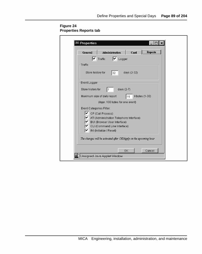
1 Click the Reports tab. See Figure 24.
2 If required, deactivate the settings for Traffic and Logger reports.
3 If required, change Event Logger parameters.
— Store history for - indicates how long report/log file should be kept on MICA.
— Maximum size of daily report - sets the size of each day’s report. You view reports in the Reports window.
— Event Categories Filter - click in the dialog box of any event category to determine which events to include in the reports.
4 Press OK to save your changes and close the Properties window.
553-3001-118 Standard 2.00 April 2000
Define Properties and Special Days Page 89 of 204
Figure 24Properties Reports tab
MICA Engineering, installation, administration, and maintenance
Page 90 of 204 Define Properties and Special Days
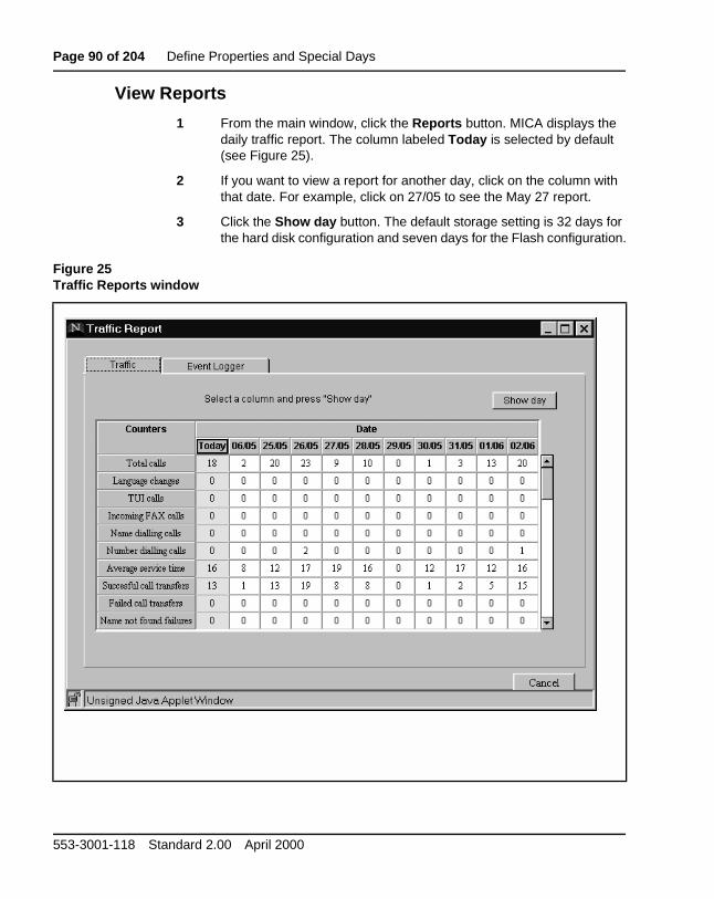
View Reports
1 From the main window, click the Reports button. MICA displays the daily traffic report. The column labeled Today is selected by default (see Figure 25).
2 If you want to view a report for another day, click on the column with that date. For example, click on 27/05 to see the May 27 report.
3 Click the Show day button. The default storage setting is 32 days for the hard disk configuration and seven days for the Flash configuration.
Figure 25Traffic Reports window
553-3001-118 Standard 2.00 April 2000
Define Properties and Special Days Page 91 of 204
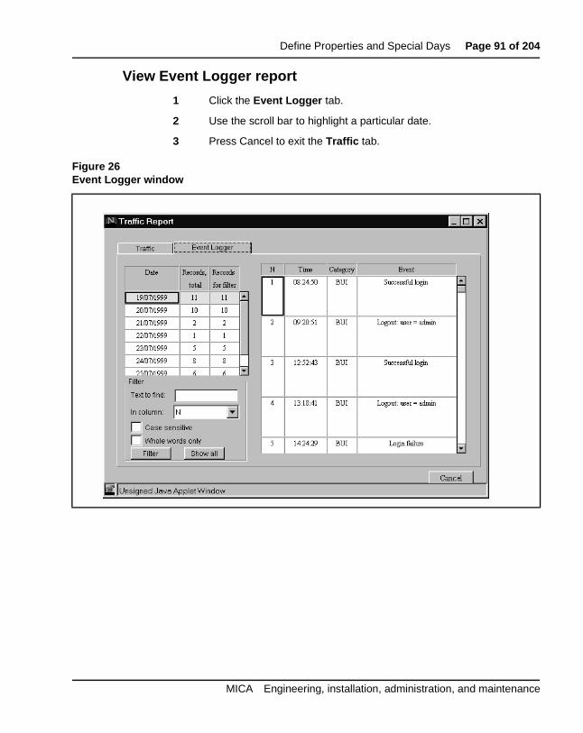
View Event Logger report
1 Click the Event Logger tab.
2 Use the scroll bar to highlight a particular date.
3 Press Cancel to exit the Traffic tab.
Figure 26Event Logger window
MICA Engineering, installation, administration, and maintenance
Page 92 of 204 Define Properties and Special Days
s
How to use the Event Logger Filter toolYou use the Filter tool to view only the records that contain specific information for a particular day. For example, you could view only recordthat contain the word login in the Event column for July 19, 1999.
1 Select a date in the date column.
2 Enter the word or words you want to find in the Text to find: box.
3 Select a column name from the list box in the In column: field.
4 If required, click Case sensitive or Whole words only.
5 Press the Filter button.
6 MICA displays only the records containing the word or words you specified. The Records total and Records for filter columns display the number of each kind of record.
How to view the Reports using FTPYou can get log and traffic files from MICA using FTP. They will not lookexactly like the BUI reports.
1 ftp: <card IP address>
2 user: user
3 password: (CLI password - default is user)
4 cd oam
5 cd traffic
6 get files ending with . try
7 cd
8 cd log
9 get all files
10 software error files are in a:oam\err
553-3001-118 Standard 2.00 April 2000
Define Properties and Special Days Page 93 of 204
r.
e up
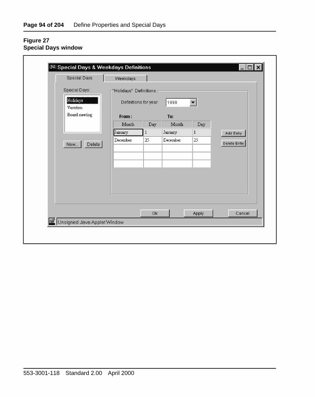
Set Special Days parametersIn this procedure, you define July 30 as a new Special day for City PoweYou can add up to three Special Days. Holidays is a default entry and cannotbe deleted. Default Holiday dates can be changed. MICA lets you defineSpecial Days parameters up to two years in advance.
You can have up to four types or groups of Special Days. You can includto 150 days a year in the Special Days groups.
1 From the Main Window, press the Special Days button (see Figure 27 for the default Special Days window).
2 Click New. Create a new Special Day called Board Meeting and press OK.
3 Define the Special Day as July 28, 1999.
4 Press Apply.
Note: If you fill in the first five rows of the Definitions table press Add Entry to add a new row.
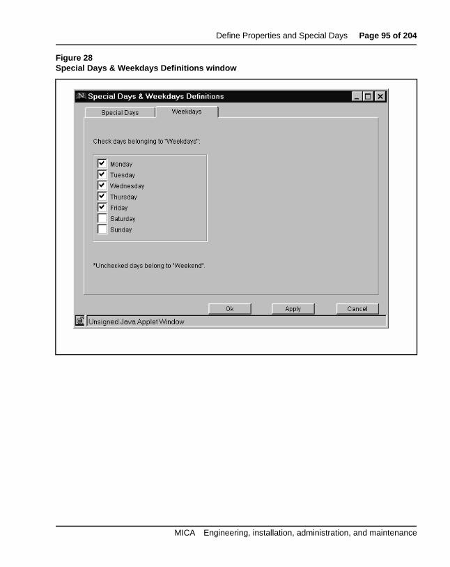
5 Click Weekdays. If required, modify the default Monday through Friday weekday definitions (see Figure 28).
MICA Engineering, installation, administration, and maintenance
Page 94 of 204 Define Properties and Special Days
Figure 27Special Days window
553-3001-118 Standard 2.00 April 2000
Define Properties and Special Days Page 95 of 204
Figure 28Special Days & Weekdays Definitions window
MICA Engineering, installation, administration, and maintenance
Page 96 of 204 Define Properties and Special Days
553-3001-118 Standard 2.00 April 2000
Page 97 of 204
88
ment
ents tains
n- lled for the
Configure a MICA serviceThese procedures explain how to configure a service and assign a treatto the service. You program different services for different requirements reached by a different dialed number. In each service, you define treatmthat are activated depending on time and caller number. A treatment coninstructions that define how MICA treats incoming calls.
Note: The MICA BUI contains a Default service which you cannot change.
Service Configuration procedure summary1 Configure a Voice Menu.
2 Define Call Screening tables.
3 Create a Service and assign treatments:
D 'HILQH#FDOOHU#JURXSV
E 'HILQH#WUHDWPHQWV
F 'HILQH#D#VFKHGXOH#IRU#WKH#WUHDWPHQW
4 Activate a service and assign a DN.
Service configuration parametersCall transfer is subject to Meridian 1 limitations. For incoming calls on nosupervised trunks, Meridian 1 allows transfer completion only after the caparty has answered. In this case the MICA will continue retry the transferup to 15 seconds. During this time, the caller is on hold and will receive hold treatment defined in Meridian 1.
MICA Engineering, installation, administration, and maintenance
Page 98 of 204 Configure a MICA service
32
ight
ur . The s use sk
lete n us. e
In the hard drive configuration, you may define up to 32 different serviceprofiles (assigned to service DNs), which lead to 32 different menus anddifferent call screening tables, based on 16 different time types and 16 different CLID types, to a maximum of 26 CLID digits.
In the Flash configuration, you may define up to eight different service profiles (assigned to service DNs), which lead to 16 different menus and edifferent call screening tables, based on 16 different time types and 16 different CLID types, up to a maximum of 26 CLID digits.
About MICA preconfigured servicesIn the hard drive configuration, MICA includes five predefined services, foon the Flash card. The hard disk configuration supports up to 32 servicesFlash configuration supports up to eight services. The predefined servicepredefined menus: 22 on the disk and 14 on the Flash card. The hard disupports up to 32 menus and the Flash supports to 16 menus.
You can keep the preconfigured services, modify them, ignore them or dethem. To delete a preconfigured service, highlight the service in the Maiwindow Services list, and press the Delete button. Then delete related menFor more information, see “MICA predefined service description” on pag129.
How to configure a service1 Login to MICA. If you need help logging in, see “How to login to the
Browser User Interface (BUI)” on page 77.
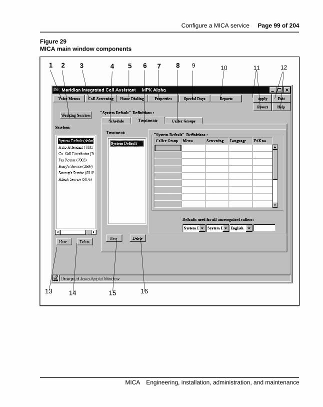
2 The MICA Main Window appears. Figure 29 shows the Main window and identifies the Main window components. Table 9 describes the components.
3 Click the Voice Menus button.
553-3001-118 Standard 2.00 April 2000
Configure a MICA service Page 99 of 204
Figure 29MICA main window components
1 2 3 4 5 6 7 8 9 10 11 12
13 14 15 16
MICA Engineering, installation, administration, and maintenance
Page 100 of 204 Configure a MICA service
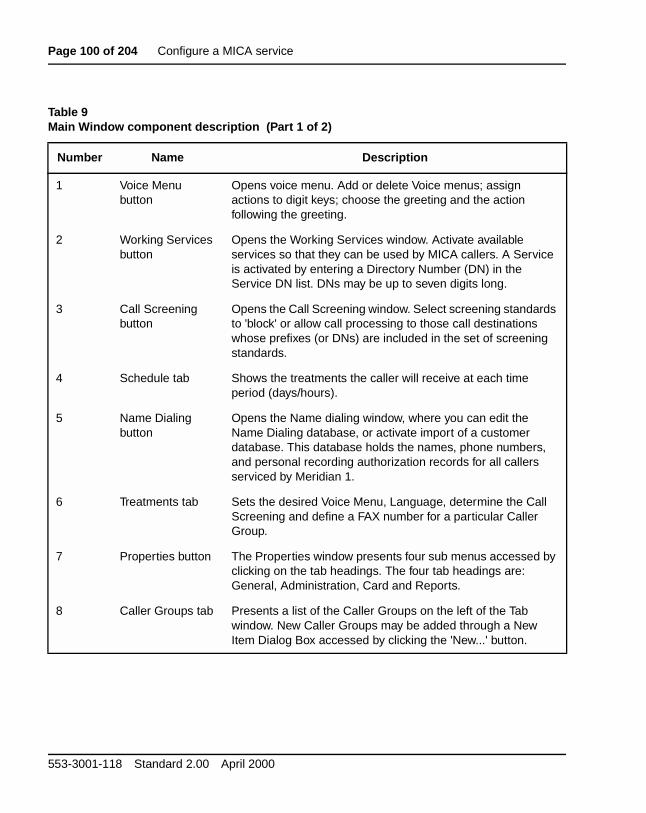
Table 9Main Window component description (Part 1 of 2)
Number Name Description
1 Voice Menu button
Opens voice menu. Add or delete Voice menus; assign actions to digit keys; choose the greeting and the action following the greeting.
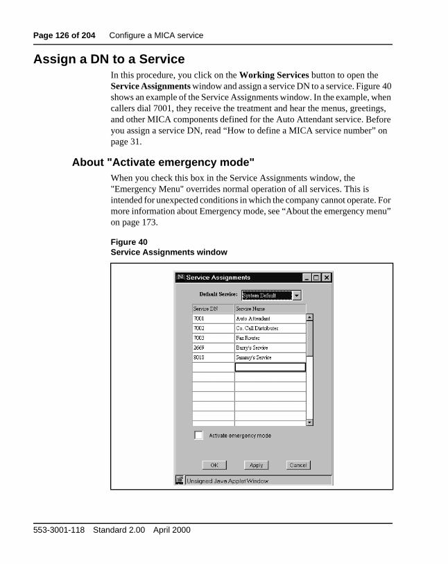
2 Working Services button
Opens the Working Services window. Activate available services so that they can be used by MICA callers. A Service is activated by entering a Directory Number (DN) in the Service DN list. DNs may be up to seven digits long.
3 Call Screening button
Opens the Call Screening window. Select screening standards to 'block' or allow call processing to those call destinations whose prefixes (or DNs) are included in the set of screening standards.
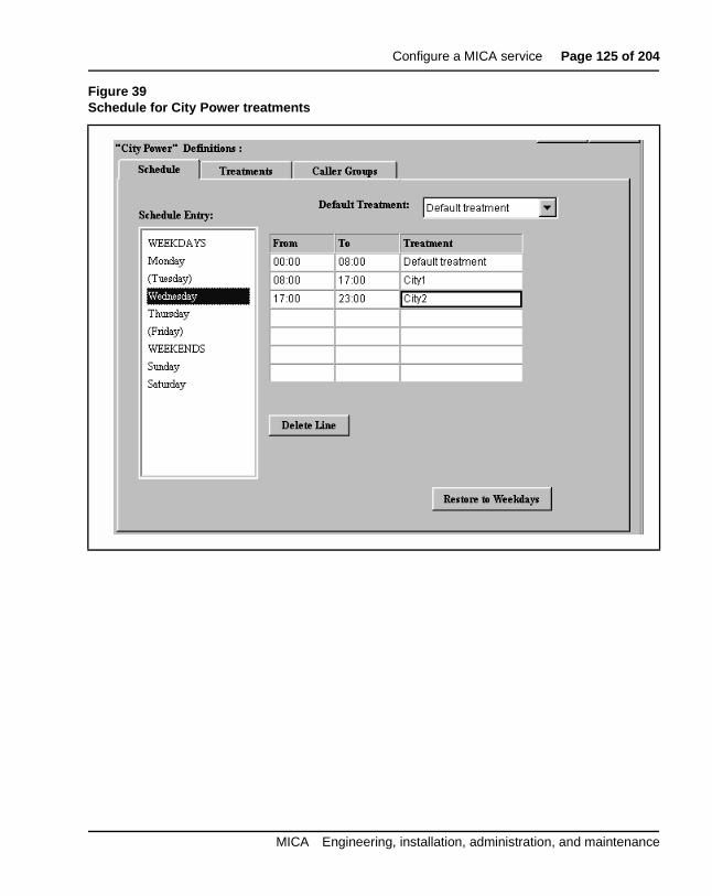
4 Schedule tab Shows the treatments the caller will receive at each time period (days/hours).
5 Name Dialing button
Opens the Name dialing window, where you can edit the Name Dialing database, or activate import of a customer database. This database holds the names, phone numbers, and personal recording authorization records for all callers serviced by Meridian 1.
6 Treatments tab Sets the desired Voice Menu, Language, determine the Call Screening and define a FAX number for a particular Caller Group.
7 Properties button The Properties window presents four sub menus accessed by clicking on the tab headings. The four tab headings are: General, Administration, Card and Reports.
8 Caller Groups tab Presents a list of the Caller Groups on the left of the Tab window. New Caller Groups may be added through a New Item Dialog Box accessed by clicking the 'New...' button.
553-3001-118 Standard 2.00 April 2000
Configure a MICA service Page 101 of 204
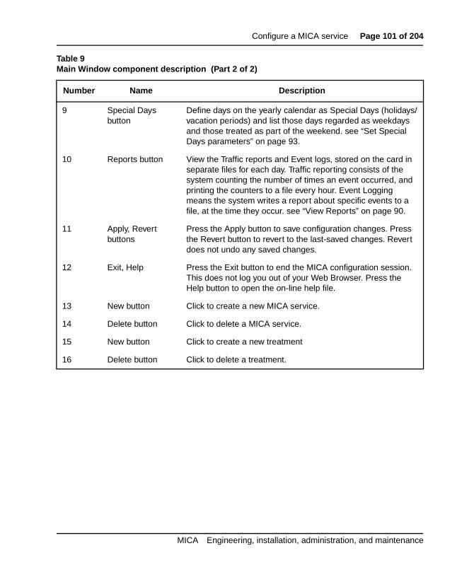
9 Special Days button
Define days on the yearly calendar as Special Days (holidays/vacation periods) and list those days regarded as weekdays and those treated as part of the weekend. see “Set Special Days parameters” on page 93.
10 Reports button View the Traffic reports and Event logs, stored on the card in separate files for each day. Traffic reporting consists of the system counting the number of times an event occurred, and printing the counters to a file every hour. Event Logging means the system writes a report about specific events to a file, at the time they occur. see “View Reports” on page 90.
11 Apply, Revert buttons
Press the Apply button to save configuration changes. Press the Revert button to revert to the last-saved changes. Revert does not undo any saved changes.
12 Exit, Help Press the Exit button to end the MICA configuration session. This does not log you out of your Web Browser. Press the Help button to open the on-line help file.
13 New button Click to create a new MICA service.
14 Delete button Click to delete a MICA service.
15 New button Click to create a new treatment
16 Delete button Click to delete a treatment.
Table 9Main Window component description (Part 2 of 2)
Number Name Description
MICA Engineering, installation, administration, and maintenance
Page 102 of 204 Configure a MICA service
ty
nts.
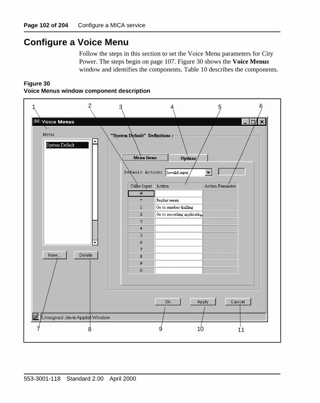
Configure a Voice MenuFollow the steps in this section to set the Voice Menu parameters for CiPower. The steps begin on page 107. Figure 30 shows the Voice Menus window and identifies the components. Table 10 describes the compone
Figure 30Voice Menus window component description
1 2 3 4 5 6
7 8 9 10 11
553-3001-118 Standard 2.00 April 2000
Configure a MICA service Page 103 of 204
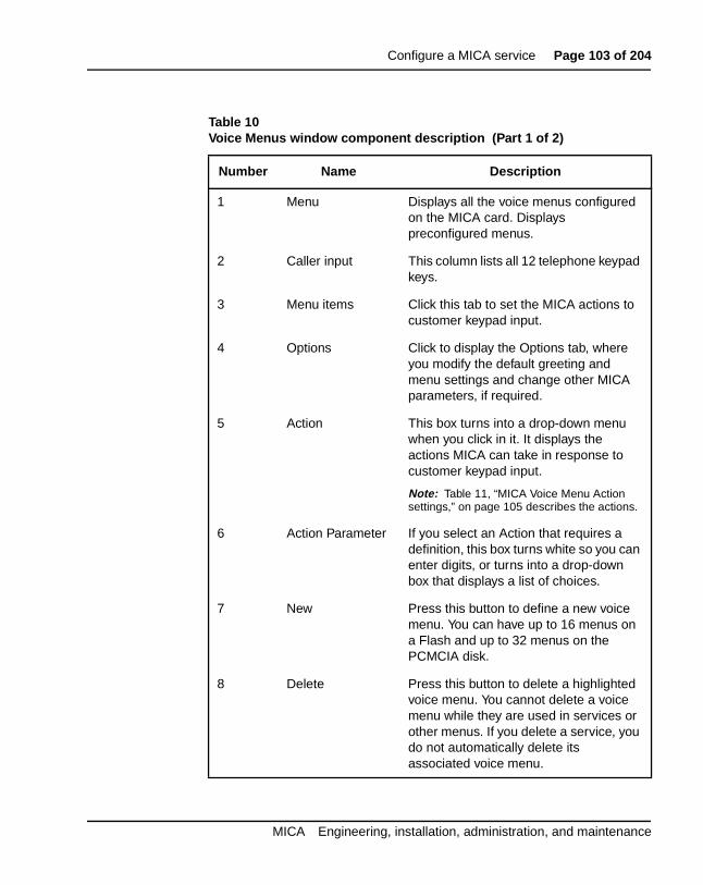
Table 10Voice Menus window component description (Part 1 of 2)
Number Name Description
1 Menu Displays all the voice menus configured on the MICA card. Displays preconfigured menus.
2 Caller input This column lists all 12 telephone keypad keys.
3 Menu items Click this tab to set the MICA actions to customer keypad input.
4 Options Click to display the Options tab, where you modify the default greeting and menu settings and change other MICA parameters, if required.
5 Action This box turns into a drop-down menu when you click in it. It displays the actions MICA can take in response to customer keypad input.
Note: Table 11, “MICA Voice Menu Action settings,” on page 105 describes the actions.
6 Action Parameter If you select an Action that requires a definition, this box turns white so you can enter digits, or turns into a drop-down box that displays a list of choices.
7 New Press this button to define a new voice menu. You can have up to 16 menus on a Flash and up to 32 menus on the PCMCIA disk.
8 Delete Press this button to delete a highlighted voice menu. You cannot delete a voice menu while they are used in services or other menus. If you delete a service, you do not automatically delete its associated voice menu.
MICA Engineering, installation, administration, and maintenance
Page 104 of 204 Configure a MICA service
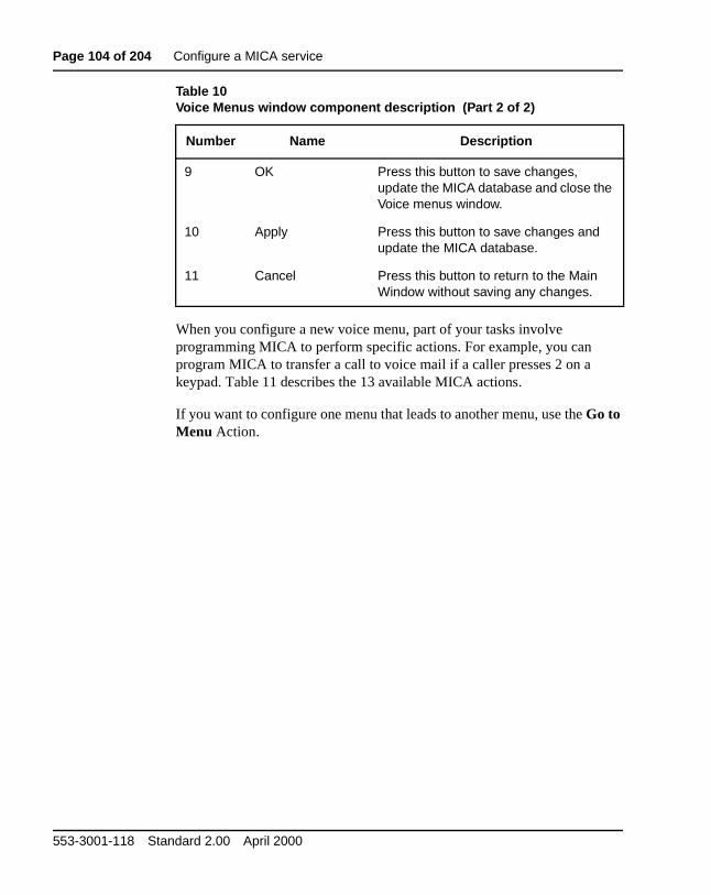
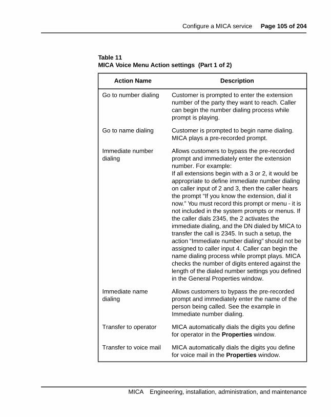
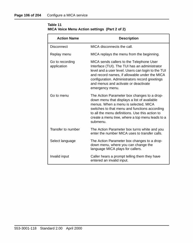
When you configure a new voice menu, part of your tasks involve programming MICA to perform specific actions. For example, you can program MICA to transfer a call to voice mail if a caller presses 2 on a keypad. Table 11 describes the 13 available MICA actions.
If you want to configure one menu that leads to another menu, use the Go to Menu Action.
9 OK Press this button to save changes, update the MICA database and close the Voice menus window.
10 Apply Press this button to save changes and update the MICA database.
11 Cancel Press this button to return to the Main Window without saving any changes.
Table 10Voice Menus window component description (Part 2 of 2)
Number Name Description
553-3001-118 Standard 2.00 April 2000
Configure a MICA service Page 105 of 204
Table 11MICA Voice Menu Action settings (Part 1 of 2)
Action Name Description
Go to number dialing Customer is prompted to enter the extension number of the party they want to reach. Caller can begin the number dialing process while prompt is playing.
Go to name dialing Customer is prompted to begin name dialing. MICA plays a pre-recorded prompt.
Immediate number dialing
Allows customers to bypass the pre-recorded prompt and immediately enter the extension number. For example:If all extensions begin with a 3 or 2, it would be appropriate to define immediate number dialing on caller input of 2 and 3, then the caller hears the prompt “If you know the extension, dial it now.” You must record this prompt or menu - it is not included in the system prompts or menus. If the caller dials 2345, the 2 activates the immediate dialing, and the DN dialed by MICA to transfer the call is 2345. In such a setup, the action “Immediate number dialing” should not be assigned to caller input 4. Caller can begin the name dialing process while prompt plays. MICA checks the number of digits entered against the length of the dialed number settings you defined in the General Properties window.
Immediate name dialing
Allows customers to bypass the pre-recorded prompt and immediately enter the name of the person being called. See the example in Immediate number dialing.
Transfer to operator MICA automatically dials the digits you define for operator in the Properties window.
Transfer to voice mail MICA automatically dials the digits you define for voice mail in the Properties window.
MICA Engineering, installation, administration, and maintenance
Page 106 of 204 Configure a MICA service
Disconnect MICA disconnects the call.
Replay menu MICA replays the menu from the beginning.
Go to recording application
MICA sends callers to the Telephone User Interface (TUI). The TUI has an administrator level and a user level. Users can login to the TUI and record names, if allowable under the MICA configuration. Administrators record greetings and menus and activate or deactivate emergency menu.
Go to menu The Action Parameter box changes to a drop-down menu that displays a list of available menus. When a menu is selected, MICA switches to that menu and functions according to all the menu definitions. Use this action to create a menu tree, where a top menu leads to a submenu.
Transfer to number The Action Parameter box turns white and you enter the number MICA uses to transfer calls.
Select language The Action Parameter box changes to a drop-down menu, where you can change the language MICA plays for callers.
Invalid input Caller hears a prompt telling them they have entered an invalid input.
Table 11MICA Voice Menu Action settings (Part 2 of 2)
Action Name Description
553-3001-118 Standard 2.00 April 2000
Configure a MICA service Page 107 of 204
e
Create a new voice menuIf your MICA application includes DNIS and/or CLID, create two new voicmenus and configure each one according to the steps in this section.
1 From the Main Window , press the Voice Menus button. The Voice Menus window appears. Press the New button (see Figure 30).
2 Create a new menu named City Power that is based on System Default settings, as shown in Figure 31. Press OK to accept the new menu and return to the Voice Menus window Menu Items tab.
Figure 31New Menu window
MICA Engineering, installation, administration, and maintenance
Page 108 of 204 Configure a MICA service
A
Configure the Voice Menu OptionsIn this section, you program new entries for the Announcements to Caller Greeting and Menu Options. You select the First Action After Greeting MICA takes when answering calls for City Power. You set the actions MICperforms if the City Power caller exceeds the timeout settings for no action or call duration. Figure 32 shows the Voice Menus Options window.
Figure 32Voice Menus Options window
553-3001-118 Standard 2.00 April 2000
Configure a MICA service Page 109 of 204
1 From the Voice Menus window Menu Items tab, highlight City Power in the Menu list. Press the Options tab to display the Options window.
2 Press the Voice Prompts Manager button. This opens the Voice Prompts Manager window Greeting prompts tab.
3 In this step, you create a Greeting Prompt for City Power named 30 City Power . Place your cursor in the ID number column and type in 30. MICA accepts any number between 1 and 32 if you have a hard disk, or between 1 and 16 if you have a Flash card. Press the Tab key to move to the Name column and type in City Power as the name for the greeting prompt.
When you record the greeting that MICA plays for City Power callers, you use the Greeting prompt ID number as a reference. You record the greeting through the MICA Telephone User Interface (TUI).
4 In this step, you create a Greeting Prompt for City Power named 30 City Power menu . Press the Menu prompts tab. Define an ID number for the MICA menu prompt. Place your cursor in the ID number column and type in a number between 1 and 32 if you have a hard disk, or between 1 and 16 if you have a Flash card. Press the Tab key to move to the Name column and type in a name for the menu prompt. Create a Menu named 30.City Power menu.
When you record the menu prompts that MICA plays for City Power callers, you use the Menu prompt ID number as a reference. You record the menu through the MICA Telephone User Interface (TUI).
5 Press OK to return to the Voice Menus Options window.
Change Announcements to Caller default settingsIn this procedure, you replace the default settings for Greeting and Menu Options in the Announcements to Caller box.
1 In the Greeting field, click the down arrow to display the drop-down menu. Click the Greeting prompt ID you created for City Power.
2 In the Menu Options field, click the down arrow to display the drop-down menu. Click on the Menu prompt ID you created for City Power.
3 Press the Apply button at the bottom of the Voice Menu Options window to save the Announcements to Caller changes.
MICA Engineering, installation, administration, and maintenance
Page 110 of 204 Configure a MICA service
ty
or
tings for
ings. d 3.
Change First Action After Greeting default setting (optional)This field defines what action MICA takes after playing the greeting. Go to Menu is the default setting for MICA’s first action after greeting. For the CiPower example, leave the default setting so MICA plays the 30. City Power Menu1. If your application requires a different parameter, perform steps 12 and 3.
Note: In an ACD front-end application, selecting Transfer to DN forwards calls to the predefined destination after playing the promptwithout waiting for caller input.
1 If you choose any action other than Go to Menu , only the greeting plays. The menu options voice menu does not play.
2 If you click the Transfer to DN radio button, the gray box turns white and you enter the DN MICA uses to transfer the calls.
3 If you click Disconnect, MICA disconnects the call after playing the greeting.
4 Press the Apply button to save the changes.
Change No Action and Call Duration default settings (optional)These settings define what MICA does if a caller exceeds the timeout setfor no action or exceeds the call duration parameter. The default settingNo Action is Replay Menu. The default setting for Call Duration is Disconnect. For the City Power example, do not change the default settIf your application requires a different parameter, perform steps 1 or 2 an
1 If you want to change the default action for MICA after a caller exceeds the timeout for No Action, click in the Action box. The Action box changes to a drop-down menu. Select an action from the menu. Table 11 describes each action.
2 If you want to change the default action for MICA after a caller exceeds the timeout for Call duration , click in the Action box. The Action box changes to a drop-down menu. Select an action from the menu. Table 11 on page 105 describes each action.
3 Press the Apply button to save the changes.
Define Menu ItemsIn the previous step, you created a new Menu Prompt named 30.City Power Menu1 and selected it in the Menu Options field in the Announcements to caller.
553-3001-118 Standard 2.00 April 2000
Configure a MICA service Page 111 of 204
r for sible d in
ult
d a t
ify ast
ch is
you enu
In this step, you define the action MICA takes when it plays 30.CityPoweMenu 1 and a caller presses a keypad key. If required, set up one actioneach keypad key. See Table 11 on page 105 for a description of the posactions. MICA uses the default action when callers press a key not definethe table.
1 From the Options tab, press the Menu Items tab. If required, select City Power from the Menu list.
Note: Because you based the City Power voice menu on the defasetting, the Menu Items tab displays the MICA default settings.
2 Place the cursor in the Action box next to the 1 in the Caller Input column. The Action box changes to a drop-down menu. Select an action from the menu. Table 11 describes each action.
Editing the emergency menuMICA ships with a default emergency menu that offers number dialing anrecording application. The emergency menu options are slightly differenthan the normal menu options:
• Announcement files have fixed name and number. You only specwhether to provide announcements or not. You must specify at leone announcement.
• You must specify a screening table, since the emergency menustands alone and is not in context of a specific service.
• The language is preset to use the system default language, whithe first language in language set.
• One of the menu items should be the recording procedure, sinceuse the recording procedure used to deactivate the emergency mthrough the TUI.
To edit the emergency menu, carry out the following steps:
1 Select the emergency menu from the list of menus in the Voice Menus window (see Figure 33).
2 Set menu items as in a regular menu.
3 Define greetings and menus in the options tab (see Figure 34).
4 Select a screening table to use when you activate the emergency menu.
MICA Engineering, installation, administration, and maintenance
Page 112 of 204 Configure a MICA service
Figure 33Emergency menu Menu Items tab
553-3001-118 Standard 2.00 April 2000
Configure a MICA service Page 113 of 204
Figure 34Emergency menu default Options tab
MICA Engineering, installation, administration, and maintenance
Page 114 of 204 Configure a MICA service
d to.
t “If
to, .
ll n A r sfer
#
use
Define Call ScreeningYou define call screening parameters to block MICA from dialing certaindestinations after customers enter the number they want to be transferreFor example:
MICA answers a call. The caller presses 2 after hearing the MICA prompyou know the number you want to reach, press 2".
Then MICA prompts: “Please enter the number you wish to be transferredfollowed by the pound sign”. The customer enters 6011526725551212#
MICA compares the dialing prefixes to the privileges you define in the cascreening table. If you allow MICA to transfer calls to numbers that begiwith 6011 (which is an international dialing code in some countries), MICdials the digits and transfers the call. If you do not allow MICA to transfecalls to destinations that begin with 6011, the caller is notified that the tranis denied.
MICA only screens calls after the caller enters the digits and presses thekey. An entry can be the prefix of another entry. When MICA checks thedialed number, call processing software selects the longest match. For example, you can deny the dialing prefix 6, but allow the prefix 69, becaMICA looks for the longest match.
Note: The default setting is that all calls are Allowed.
1 From the Main Window, press the Call Screening button. Figure 35 shows the Call Screening table default settings.
2 Click New. Create a new Screening Table named City Power based on the default settings. Press OK to return to the Call Screening Window. In the hard disk configuration, you may have up to 32 call screening tables. The Flash card can contain up to eight call screening tables.
3 In the Dialed Prefix list, enter outgoing call prefixes. The Dialed Prefix list can hold up to 100 entries. The maximum prefix digit length is 20 digits. See Figure 36.
4 Click in the Authorization box for each dialed prefix entry. The Authorization box turns into a drop-down menu that displays Allow or Deny settings. Pick one setting for each prefix in the Dialed Prefix column.
553-3001-118 Standard 2.00 April 2000
Configure a MICA service Page 115 of 204
5 Set the default Authorization box to Allow or Deny dialed prefixes not listed in the Dialed prefix box.
6 Press OK to save the changes. MICA returns you to the Main Window.
Figure 35Call Screening window
MICA Engineering, installation, administration, and maintenance
Page 116 of 204 Configure a MICA service
Figure 36Call screening table for City Power
553-3001-118 Standard 2.00 April 2000
Configure a MICA service Page 117 of 204
all nts,
can
. One
that at
nt
Create a Service and assign treatmentsIn this procedure, you create a new service, then define caller groups, ctreatments and set a schedule. Each Service is made up of three elemedefined per service. These are:
• Caller Groups
• Treatments
• Schedule
Each element is a tab on the Main Window .
Note: Caller groups, schedules and treatments are specific to each service. Menus and screening tables are system resources and youuse them for multiple services.
Create a new service
1 From the Main Window, press the New button under the Services list. You can have 32 services on the hard disk and eight on the Flash.
2 Create a new service based on the default settings. Press OK to return to the Schedule tab of the Main Window. If required, you can include the Service DN in the service name.
Create caller groupsMICA routes calls according to their origin (caller identification). If all callers receive one treatment, skip to the Treatments tab. If you use CLID and want certain callers to receive special treatment, create caller groupsprefix may be a prefix of another. Call processing software looks for the longest match. For example, you create a caller group with the prefix 612includes all people in Minnesota. You can create another caller group thuses the prefix 612434 in Minneapolis, Minnesota.
Caller Groups descriptionCaller groups define incoming calls as belonging to different groups according to CLID. MICA handles calls differently for members of differecaller groups.
MICA Engineering, installation, administration, and maintenance
Page 118 of 204 Configure a MICA service
ialed king
ber
by his
For example, you create a group of prefixes named French. It includes prefixes 1416 and 1807. When MICA answers a call that includes these dprefixes, it plays a menu in French and transfers the call to a French-speaACD agent.
A Prefix or number can only belong to one caller group. Define up to 15 Caller Groups. Up to 100 prefixes can be defined. Each prefix and/or nummay be up to 26 digits long.
A list showing all the caller numbers in all the listed caller groups (sortednumber sequence) is displayed by clicking the Show all callers button. Tlist is for viewing only and may not be edited.
Caller Groups configuration procedureIn this step, you create two new caller groups for the Moore Company.
1 From the Main Window Schedule tab, click on a service in the Services list and click the Caller Groups tab.
2 Click the New button at the bottom of the Caller group list. Create a new Caller Group named French based on the default setting and press OK. The word French appears in the Caller group list.
3 Click on French in the Caller group list. In the Prefixes list, enter the prefixes that you want to include in the caller group French.
4 Create other caller groups and define prefixes as required.
553-3001-118 Standard 2.00 April 2000
Configure a MICA service Page 119 of 204
ICA p to ns.
the A t the can
d for ll
.
Define TreatmentsIn this procedure, you select a service and define a treatment that tells Mhow to answer and route incoming calls to that service. You can define u16 treatments, including default, for both Flash and hard disk configuratioYou define different treatments if you plan to handle calls differently according to when MICA receives the call. Otherwise, you may overwrite system default treatment with the desired call-handling settings and MICwill treat all calls the same, including weekends and vacations. You selecdefault and make your definitions in it. You just made a new service. You change the default treatment inside a service you created.
Figure 37 shows an example of a treatment named City1, which is defineCity Power. City Power does not use Caller Groups because MICA treats acalls to City Power the same way. Note that the Caller Group box is empty. Deleting a treatment will remove it from all schedules in which it appearsThe maximum length of the FAX DN is 20 digits.
Option 1 - Define a treatment for a non-caller-group service
1 Click on a Service in the Services: box.
2 Click the Treatments tab.
3 Click the New button.
4 Create a new Treatment and press OK.
5 Highlight the new Treatment in the Treatments box.
6 Look at the bottom of the screen. Under the words Use for all unrecognized calls you see three drop-down menu lists:
D &OLFN#LQ#WKH#OHIW#GURS0GRZQ#PHQX#OLVW#DW#WKH#ERWWRP#RI#WKH#0HQX#FROXPQ1#$#OLVW#RI#DOO#WKH#9RLFH#0HQXV#DYDLODEOH#RQ#0,&$#DSSHDUV1#6HOHFW#&LW\#3RZHU1#0,&$#DQVZHUV#DQG#URXWHV#FDOOV#DFFRUGLQJ#WR#WKH#SDUDPHWHUV#\RX#VHW#XS#IRU#WKH#PHQX#QDPHG#&LW\#3RZHU#LQ#WKH#9RLFH#0HQXV#WDE1
E &OLFN#LQ#WKH#PLGGOH#GURS0GRZQ#PHQX#DW#WKH#ERWWRP#RI#WKH#6FUHHQLQJ#FROXPQ1###6HOHFW#&LW\#3RZHU1#0,&$#XVHV#WKH#FDOO#VFUHHQLQJ#LQIRUPDWLRQ#\RX#GHILQHG#IRU#&LW\#3RZHU#LQ#WKH#&DOO#6FUHHQLQJ#WDE1
MICA Engineering, installation, administration, and maintenance
Page 120 of 204 Configure a MICA service
F &OLFN#LQ#WKH#ULJKW#GURS0GRZQ#PHQX#DW#WKH#ERWWRP#RI#WKH#/DQJXDJH#FROXPQ1#6HOHFW#WKH#DSSURSULDWH#ODQJXDJH1#0,&$#XVHV#WKH#ODQJXDJH#WR#DQVZHU#FDOOV1#0,&$#FDUGV#LQ#WKH#)/$6+#FRQILJXUDWLRQ#VXSSRUW#RQO\#(QJOLVK1
7 If you want MICA to use the FAX extension entered in the Properties/General tab, leave the box at the bottom of the FAX no. column empty. If you want MICA to use another FAX number for this treatment, type another FAX number in the box.
8 Press Apply to save your changes.
Figure 37Treatments window (no caller group defined)
MICA uses the settings in these list boxes for Menu,
Screening and Language if you do not use caller groups.
553-3001-118 Standard 2.00 April 2000
Configure a MICA service Page 121 of 204
ing
ed
caller
Option 2 - Define treatment for a service that usesa caller group
In this procedure, you define one treatment providing different call-handlfor callers from different caller groups.
Stage 1: Set the call-handling parameters for callers in the caller group namFrench.
Stage 2: Set the call-handling parameters for all other callers.
Figure 38 shows an example of a treatment named Moore, which uses a group for the Moore Vacuum Cleaner company.
Figure 38Treatments window
MICA Engineering, installation, administration, and maintenance
Page 122 of 204 Configure a MICA service
Define a treatment
1 Click on a Service in the Services: box.
2 Click the Treatments tab.
3 Click the New button.
4 Create a new Treatment called Moore1 and press OK.
Stage 1 - Define call handling for Caller Group “French”
1 Highlight Moore1 in the Treatments box.
2 Each cell in the left column under Caller Groups displays one caller group that is assigned to that service. Select French, the caller group name you created in the Caller Group tab. MICA uses the parameters you set in the French Caller Group to route calls according to CLID.
3 Click in the box beneath Menu . A drop-down list appears. It shows all the voice menus available on MICA. Select Moore . MICA uses the voice menu parameters you created for Moore in the Voice Menus tab.
4 Click in the box beneath Screening . A drop-down list appears that shows all the call screening groups available on MICA. Select Moore . MICA uses the call screening parameters you created for Moore in the Call Screening tab.
5 Click in the box beneath Language . A drop-down list appears that shows all the call screening groups available on MICA. Select French . MICA answers all calls in French when it sees an incoming call with a prefix that matches the prefixes defined for French in the Caller Group tab.
6 If you want MICA to use the FAX extension entered in the Properties/General tab, leave the FAX no. column empty. If you want MICA to use another FAX number for this treatment, type another FAX number in the box.
7 Press Apply to save your changes. It is not necessary to define menus, call screening language and FAX number on the bottom of the screen. MICA uses the definitions contained in the list boxes beneath the Menus, Screening and Language columns.
553-3001-118 Standard 2.00 April 2000
Configure a MICA service Page 123 of 204
he
Stage 2 - Define call handling for "all other callers"At this point you define how MICA treats and routes calls for all callers to tservice whose dialing prefixes are not defined in the French caller group.
1 Look at the bottom of the screen. Under the words Use for all unrecognized calls you see three drop-down menu lists.
2 Click in the left drop-down menu list at the bottom of the Menu column. A list of all the Voice Menus available on MICA appears. Select Moore . MICA answers and routes calls according to the parameters you set up for the menu named Moore in the Voice Menus tab.
3 Click in the middle drop-down menu at the bottom of the Screening column. Select System Default . MICA uses default call screening information.
4 Click in the right drop-down menu at the bottom of the Language column. Select English. MICA uses English to answer calls whose prefixes are not part of the French caller group.
5 If you want MICA to use the FAX extension entered in the Properties/General tab, leave the box at the bottom of the FAX no. column empty. If you want MICA to use another FAX number for this treatment, type another FAX number in the box.
6 Press Apply to save your changes.
MICA Engineering, installation, administration, and maintenance
Page 124 of 204 Configure a MICA service
ses
een
m
Set a treatment scheduleIn this section, you select a service and define which treatments MICA ufor the service according to time of day and day of week.
Figure 39 shows the following:
• MICA uses the default treatment for callers on Wednesdays betwmidnight (00:00 hours) and 8 am (08:00 hours).
• MICA uses the City1 treatment for callers between 8 am and 5 p(08:00 and 17:00 hours).
• MICA uses the City2 treatment for callers between 5 pm and midnight (17:00 to 00:00 hours).
• Unspecified times and days receive the default treatment.
Note: If you want MICA to use a certain treatment for a whole day, choose this treatment from the Default Treatment drop-down menu.
How to set a treatment schedule
1 From the Treatments tab, press Schedule.
2 Click on a Service from the Services list.
3 Depending on your application, select a day from the schedule entry list, or select Weekdays or Weekends to assign treatments for those groups of days.
4 Click in the From box and type in the time you want MICA to start using the treatment. Important: Calculate the time using the 24-hour clock format, where midnight is 00:00, and use hh:mm format to enter the hours in the From and To boxes in 15-minute intervals.
5 Click in the To box and type in the time you want MICA to stop using the treatment.
6 Click in the Treatment box and select a treatment for MICA to use during the time period you specified.
7 Schedule other treatments as required. MICA uses the default treatment for unspecified times.
If you want MICA to give a whole day the same treatment, select one treatment and do not specify any hours. If you do not specify weekend, holiday or vacation treatments, MICA uses the Default treatment.
553-3001-118 Standard 2.00 April 2000
Configure a MICA service Page 125 of 204
Figure 39Schedule for City Power treatments
MICA Engineering, installation, administration, and maintenance
Page 126 of 204 Configure a MICA service
40 hen
ngs,
n
. For nu”
Assign a DN to a ServiceIn this procedure, you click on the Working Services button to open the Service Assignments window and assign a service DN to a service. Figureshows an example of the Service Assignments window. In the example, wcallers dial 7001, they receive the treatment and hear the menus, greetiand other MICA components defined for the Auto Attendant service. Before you assign a service DN, read “How to define a MICA service number” opage 31.
About "Activate emergency mode"When you check this box in the Service Assignments window, the "Emergency Menu" overrides normal operation of all services. This is intended for unexpected conditions in which the company cannot operatemore information about Emergency mode, see “About the emergency meon page 173.
Figure 40Service Assignments window
553-3001-118 Standard 2.00 April 2000
Configure a MICA service Page 127 of 204
n 1
ark
list
lt
at . You rvice
ult ized
vice All s
s not ials
Service DN parameters
• Service numbers can only be the numbers defined on the Meridiato route to the MICA card.
• You can only use numbers that will appear on the display of theMICA units, so MICA recognizes the number.
• You can only assign one DN to each service.
• Do not define DN 9999999. The system uses this number to mservices with no DN defined.
• You can enter up to seven digits in the Service DN list.
• MICA sorts the Service DNs according to DN, not according to Service Name. To remove a service from the Working Service window. Deleting the DN deactivates the Service.
• To store services in the Service Assignments list for future use, them and delete their DNs.
• To edit the Service names, click in the Service Names list.Defauservice explanation
When you click the Default Service combo box, MICA lists all services thhave an assigned DN. You can select any service as the Default Servicecannot delete a service used as a Default Service. When you select a sewith an assigned DN as the default service (7001 Auto-Attendant, for example), the service loses its DN (see Figure 41). MICA uses the Defaservice to handle incoming calls where the dialed number is not a recognservice DNs. This can occur in two ways:
1 Calls are routed to MICA using numbers that do not appear in the serassignment table. An example would be an application using DNIS. calls to the DID route terminate on the MICA. DNIS digits are used athe service number.
2 The dialed number appears in the service assignment table, but doeappear on the MICA set display. An example of this is when a caller dthe MICA ACD queue DN that does not reach the set display.
MICA Engineering, installation, administration, and maintenance
Page 128 of 204 Configure a MICA service
Working service assignment procedures
1 From the Main Window schedule tab, click on a service in the Services list.
2 Press the Working Services button. This opens the Service Assignments window.
3 In the Service DN column, enter a DN up to seven digits.
4 Press the Apply button.
Figure 41Auto Attendant defined as the Default Service
553-3001-118 Standard 2.00 April 2000
Page 129 of 204
88
the mer
d
MICA predefined service descriptionThis section describes the MICA preconfigured services. You can modifyservices to fit your application. The preconfigured services use the custodialing plan listed in Table 12. The Flash configuration contains four predefined services. The hard disk configuration contains five predefineservices.
Table 12Predefined service customer dialing plan (Part 1 of 2)
Characteristic Description
Operator 0
Express messaging service 5000.
GateHouse 5500.
Local DNs 2, 3, 4, 5XXX
Network access 6XXX
DID access 7, 8XXX
Main company Fax 8000.
Dept. Fax machines 800X.
PSTN access 9
Administrator DNs (internal) 5001, 5002
Administrator DN (external) 222-2000
MICA Engineering, installation, administration, and maintenance
Page 130 of 204 MICA predefined service description
n
ce,
le is
o the
Predefined service descriptionThe MICA preinstalled services are named:
• Auto Attendant Service
• Company Call Distributer service (menu based service)
• Fax Routing service
• Two Call Center Front End services providing DNIS differentiatio
Note: On a flash card, there is only one Call Center Front End serviand it has fewer menus.
• MICA uses one screening table for all callers to all services, including when Emergency menu is used. The call screening tabis the “block outgoing calls” table. It is initially defined as blockingcalls beginning with the digit ‘9’, but allowing calls to no. 9-408-222-3333.
In services other than the Fax Router service, Faxes are all transferred tMain company Fax.
Company Voice Mail Box 5005.
Call Center salespeople 1XXX.
Table 12Predefined service customer dialing plan (Part 2 of 2)
Characteristic Description
553-3001-118 Standard 2.00 April 2000
MICA predefined service description Page 131 of 204
ll
rth
ed
Auto Attendant Service descriptionService Name: Auto Attendant
Reached by number: 7001
Caller groups (see Figure 42):
1 Administrators (CLID 5001, 5002, 222-2000): allowed to enter administrator interface and record greetings and menus in the TUI.
2 French speakers (CLID prefix: 514 (Montreal): These callers hear arecordings in French.
3 All callers who do not belong to the above groups are considered NoAmerican English speakers.
Note: On Flash card, there is no multi-language support.
The Auto Attendant service treatments and schedule description
1 Office Hours: from 9 am to 5 pm Monday through Friday.
2 After Office Hours: all other hours Monday through Friday.
3 Weekend and Holiday schedule: Saturday, Sunday, January 1 and December 25.
4 On Tuesdays, Working hours are 9 am to 4 pm, so Tuesday is definseparately.
5 To return to the Weekdays definition, select Tuesday, then press “Restore to Weekdays” button.
MICA Engineering, installation, administration, and maintenance
Page 132 of 204 MICA predefined service description
Figure 42Auto-attendant service caller groups
553-3001-118 Standard 2.00 April 2000
MICA predefined service description Page 133 of 204
Figure 43Auto-attendant treatments
MICA Engineering, installation, administration, and maintenance
Page 134 of 204 MICA predefined service description
lled
ou
ed
you 2.”
. If 0.
tt.-re
the
s
for
nu t
ng mpt
The greeting and menu in “Office Hours” treatment: The menu used is ca“Auto Att.-office” “Welcome to the Auto Attendant service. Press 1 for number dialing, 2 for name dialing, 3 for operator assistance, press 4 if ywish to be transferred to the express messaging service.”
• This service uses greeting prompt 1 and menu prompt 1.
• The MICA properties define the Operator number as 0, and the express messaging number as 5000.
• The “After Office Hours” treatment greeting uses the menu nam“Auto Att.-late”: “Welcome to the Auto Attendant service. Our office hours are from 9 am to 5 pm. For an emergency press 1. If wish to be transferred to the express messaging service, press Greeting prompt no. 2 and menu prompt no.2 are used.
• If caller presses 1, MICA transfers call to the Gate House (5500)caller presses 2, call is transferred to express mail service, x500
• The greeting in “Weekend” treatment: The menu used is “Auto Aweekend”. “Welcome to the Auto Attendant service, our offices aclosed today, please call back on a weekday. In case of an emergency press 1”. If caller presses 1, call will be transferred toGate House (5500).
• Greeting prompt no. 3 and menu prompt no. 3 are used.
• The greeting in “Holiday” treatment uses the menu “Auto Att.-closed” “Welcome to the Auto Attendant service, our offices areclosed today, please call back on a weekday.”
Menu is defined so that call is disconnected immediately after greeting iplayed. Caller hears: “Thank you for calling, good-bye” before call is disconnected.
MICA uses Greeting prompt no. 3. On Flash card there is one treatmentWeekend&Holiday: using “Auto Att.-closed”.
The greeting for administrator CLID at all times (in all treatments): The meused is “Auto Att.-admin”. “Welcome to the Administrator Auto Attendanservice. Press 1 for number dialing, 2 for name dialing, 3 for operator assistance, press 4 if you wish to be transferred to the express messagiservice. Press 5 for the administrator interface”. MICA uses Greeting prono. 4 and menu prompt no. 4.
553-3001-118 Standard 2.00 April 2000
MICA predefined service description Page 135 of 204
same
The default name dialing database contains:
Last Name First Name Phone Number
Doe Jane 2000
Doe John 2001
Lee David 2002
Smith Kevin 2003
Jackson Paul 2004
Company call distributer (menu-based service)Service Name: Co. Call Distributer.
Reached by number: 7002
Three treatments in this service:
1 Office Hours (from 9 to 5 Monday through Friday)
2 After Office Hours (all other hours Monday through Friday)
3 Holiday and Weekend (Saturday, Sunday, Jan1st, Dec 25th)
This service uses no caller groups because MICA handles all callers the way.
Treatment descriptionOffice Hours: uses the menu named Top Level Menu.
MICA Engineering, installation, administration, and maintenance
Page 136 of 204 MICA predefined service description
r 4
In the Top Level Menu if callers press:
0 - MICA transfers call to DN 2000
1 - they reach menu 1
2 - they reach menu 2
3 - they reach menu 3
4 - they reach menu 4
5 - MICA transfers call to DN 5005.
Note: On Flash card, menu 3 and 4 do not exist. If callers press 3 oMICA plays “You have pressed an incorrect digit”.
In menu 1:Caller chooses 1 to be transferred to number 2011
Caller chooses 2 to be transferred to number 2012
Caller chooses 3 to be transferred to number 2013
Caller chooses 4 to be transferred to number 2014
Caller chooses 5 to be transferred to number 2015
In menu 2Caller chooses 1 to be transferred to number 2021
Caller chooses 2 to be transferred to number 2022
Caller chooses 3 to be transferred to number 2023
Caller chooses 4 to be transferred to number 2024
Caller chooses 5 to be transferred to number 2025
In menu 3Caller chooses 1 to be transferred to number 2031
Caller chooses 2 to be transferred to number 2032
Caller chooses 3 to be transferred to number 2033
Caller chooses 4 to be transferred to number 2034
Caller chooses 5 to be transferred to number 2035
553-3001-118 Standard 2.00 April 2000
MICA predefined service description Page 137 of 204
le
rt n e
ting
to
vice to
”.
r
t
ct
In menu 4Caller chooses 1 to be transferred to number 2041
Caller chooses 2 to be transferred to number 2042
Caller chooses 3 to be transferred to number 2043
Caller chooses 4 to be transferred to number 2044
Caller chooses 5 to be transferred to number 2045
The menu names are generic, so this service can really be used for anynumber of applications. The recordings are more specific, to give a simpexample. They may be re-recorded to fit your needs. Multilingual suppomay be easily provided by recording the same menu/greeting numbers iadditional languages, and specifying different languages in the BUI in thtreatment window for different caller groups. These menus would use recordings: greetings and menus 5 through 9. Top-level menu uses greeand menu 5, menu 1 uses greeting and menu 6 etc.
CoGreeting and menu description
Greeting 5: Welcome to the Company Call Director.”
Greeting 6: “Welcome to the Sales Department.”
Greeting 7: “Welcome to the Service Department.”
Greeting 8: “Welcome to the Support department. We will be happyassist.”
Greeting 9: “You have reached the Information Center.”
Menu 5: “For a Service Emergency press 0, for Sales press 1, for Serpress 2, for Support press 3, for Information press 4. If you would likeleave a message press 5. Press * to replay the menu.”
Menu 6: “For Local Sales press 1, for National Sales press 2, for International sales press 3, for General Product information press 4
Menu 7: “For Local Service press 1, for National Service press 2, foInternational Service press 3, for Urgent Questions press 4”.
Menu 8: “For new product support press 1, for other product supporpress 2. If you wish to register a complaint, press 4.”
Menu 9: “for General company information press 1, for specific produ
MICA Engineering, installation, administration, and maintenance
Page 138 of 204 MICA predefined service description
ple.
rd
ly. fers
d ax is s:
information press 2, for departmental information press 3, for confidential information press 4.”
For “after hours” and “holidays and weekends” treatment will be thesame as the “after hours” and “weekends” in the auto attendant exam
Note: For the example, MICA uses the same voice files for Flash Caand Hard Drive. The menu says “for Support press 3, for Informationpress 4,” even on flash card, where these options are invalid.
Fax RouterService Name: Fax Router.
Reached by number: 7003
The FAX service has five caller groups:
1 VIP (CLID prefix 555, 666, 222-2000).
2 From2or3prefix (CLID prefix 2, 3).
3 From4or5prefix (CLID prefix 4, 5).
4 From6or7prefix (CLID prefix 6, 7).
5 All other callers.
MICA FAX service descriptionMICA treats all Faxes the same way, differentiating according to CLID onIn the call treatment, The menu used is called “Fax Greeting”, which transnon-FAX callers to the Auto-Attendant service DN 7001 after playing thegreeting. Caller first hears: “The call is being transferred to the requestenumber”. Then MICA plays Greeting 10: “Hello, you have reached the FRouting service. If you are not sending a fax, please wait while your calltransferred to the Auto Attendant service.” MICA routes FAXes as follow
553-3001-118 Standard 2.00 April 2000
MICA predefined service description Page 139 of 204
)
ill
u as cial
Faxes from group are transferred to fax number1 8001
2 8002
3 8003
4 8004
5 Main Company Fax (8000)
First Call Center Front End (ACD Front service)Service Name: Call Center Front A.
Reached by number: 7004
Five caller groups:
• 0. VIP (CLID prefix 555, 666, 222-2000).
• 1. From 2 or 3 prefix (CLID prefix 2, 3)
• 2. From 4 or 5 prefix (CLID prefix 4, 5)
• 3. From 6 or 7prefix (CLID prefix 6, 7)
• 4. All other callers
Two treatments in this service:
1 Weekdays (Monday through Friday)
2 Holiday and Weekend (Saturday, Sunday, January 1, December 25
“Weekdays” treatment:Greeting 11: “Welcome to the Call Center. Your order for product A wbe handled by our salesperson in one moment.”
Greeting 12: “Welcome to the Call Center. The system recognizes yoa special customer. Your order for product A will be handled by a spesalesperson in one moment.”
Menus are defined so that call is transferred to appropriate number immediately after greeting is played. Caller hears: “The call is being transferred to the requested number”.
MICA Engineering, installation, administration, and maintenance
Page 140 of 204 MICA predefined service description
ay, e will
es ions. e re-
A3
“Weekends and Holidays” treatment: The menu used is called “Call Center closed”.
Greeting 13: “Welcome to the Call Center. Our offices are closed todplease leave a message with your name, number and request, and wcomply.”
All calls are transferred to company voice mail box: 5005. The menu namare generic, so this service can really be used for any number of applicatThe recordings are more specific, to give a simple example. They may brecorded to fit customer needs.
Note: On Flash card Caller Groups 2 and 3, and menus CallCenter and CallCenter A4 do not exist.
Table 13Treatment according to call groups
Callers from group
no
hear greeting
no in
and are transferred to DN
menu name
0 12 English 1000 CallCenter A0
1 11 English 1001 CallCenter A1
2 11 English 1002 CallCenter A2
3 11 French 1003 CallCenter A3
4 11 English 1004 CallCenter A4
553-3001-118 Standard 2.00 April 2000
MICA predefined service description Page 141 of 204
e
s a
r
ill
Second Call Center Front End (ACD Front service)Service Name: Call Center Front B.
Reached by number: 7005
Five caller groups:
• 0. VIP (CLID prefix 555, 666, 222-2000).
• 1. From 2 or 3 prefix (CLID prefix 2, 3).
• 2. From 4 or 5 prefix (CLID prefix 4, 5).
• 3. From 6 or 7 prefix (CLID prefix 6, 7).
• 4. All other callers.
Treatments:
1 1. Weekdays (Monday through Friday)
2 2. Holiday and Weekend (Saturday, Sunday, Jan1st, Dec 25th)
“Weekdays” treatment descriptionGreeting 14: “Welcome to the Call Center. Your order for product B will bhandled by our salesperson in one moment.”
Greeting 15: “Welcome to the Call Center. The system recognizes you aspecial customer. Your order for product B will be handled by a special salesperson in one moment.”
Menus are defined so that call is transferred to appropriate number immediately after greeting is played. (Caller hears: “The call is being transferred to the requested number”).
“Weekends and Holidays” treatment: the menu used is called “CallCenteclosed”.
Greeting 13: “Welcome to the Call Center. Our offices are closed today,please leave a message with your name, number and request, and we wcomply.”
Calls are transferred to company voice mail box: 5005.
MICA Engineering, installation, administration, and maintenance
Page 142 of 204 MICA predefined service description
will
Note: On Flash card this service does not exist.
“Weekends and Holidays” treatment: Menu name: “CallCenter closed”
Greeting 13: “Welcome to the Call Center. Our offices are closed today.Please leave a message with your name, number and request, and we return your call.” Calls are transferred to company voice mail box: 5005.
Note: On Flash card this service does not exist.
Table 14Treatment according to call groups
Callers from group
no
hear greeting
no in
and are transferred to DN
menu name
0 15 English 1010 CallCenter B0
1 14 English 1011 CallCenter B1
2 14 French 1012 CallCenter B2
3 14 French 1013 CallCenter B3
4 14 English 1014 CallCenter B4
553-3001-118 Standard 2.00 April 2000
Page 143 of 204
88
re in e.
How to create a name dialingdatabase in the BUI
You can create a new database directly on the MICA using the Edit featuthe Name Dialing window. MICA ships with a default five-name databas
Create a name dialing database1 From the Main window, click the Name Dialing button.
2 Click the Edit button under the General Tools column. MICA opens the default database (see Figure 44).
3 Click the Add Record button.
4 Add the new name and DN, last name first, to the database.
5 If you have the hard disk configuration, set personal recording privileges in the P.Record field. This field is “grayed-out” if you have the Flash configuration.
6 To remove the preconfigured names from the default name dialing database, highlight the names and press the Delete button.
MICA Engineering, installation, administration, and maintenance
Page 144 of 204 How to create a name dialing database in the BUI
Figure 44Name Dialing - Edit window
553-3001-118 Standard 2.00 April 2000
Page 145 of 204
88
he ICA ntered
the
t
or you one
and se. to e
od.
ent s a
Import a name dialing databaseThis chapter explains how to import a name dialing database from a fileserver to the MICA PCMCIA device. A name dialing database contains tfirst name, last name and phone number of a group of telephone users. Mmatches the names in the database to the telephone keypad characters eby callers who select “dial by name.”
The name dialing database can contain up to 10,000 names (or 1000 onFLASH card MICA option). Names can be up to 20 characters long (alphanumeric characters), including the space between the last and firsname. Phone numbers may be up to 20 digits long.
You can create a database file using spread sheet or database software,can modify the five-name MICA preconfigured default database to createdirectly on the card.
Name dialing database import descriptionTo import a name dialing database, you tell MICA the database file namethe name and location of the computer where MICA can find the databaMICA uses File Transfer Protocol (FTP) to find the database and copy itthe PCMCIA device. MICA gives you the option of importing the databasautomatically using a “wizard”, or importing it using a step-by-step meth
How a name dialing database worksFor example, Chris Lee wants to reach Alice Wilson at the ABC departmstore. He calls the store’s main number. MICA answers the call and playset of prompts. Chris is prompted to select “3” to use the Dial by Name feature.
MICA Engineering, installation, administration, and maintenance
Page 146 of 204 Import a name dialing database
e aling ey) ey).
e ris
e
ion in
de abase e
n ur
here
MICA prompts Chris to enter the last name and then the first name of thperson he wants to call. Chris enters 9 4 5. MICA searches the name didatabase for a last name starting with W, X, or Y (corresponds to the 9 kG, H, or I (corresponds to the 4 key), then J, K or L (corresponds to the 5 k
MICA finds “Wilson, Alice” in the name dialing database and checks if AlicWilson has a personal verification recording. If yes, MICA plays it and Chhears Alice’s voice. If Alice does not have a recording, MICA plays “transferring call to A-L-I-C-E W-I-L-S-O-N (pronouncing each letter of thname).
For dial-by-name, Caller may press 1 after name dialing to skip the announcement preceding the call transfer.
Note: In name dialing, the Q is represented by 7 and Z by 9.
Note: Callers can press the # sign twice to bypass the “call is beingtransferred to” announcement.
* returns callers to the main menu.
If you have the Flash option, MICA plays the spelled name to the caller.
Before you import a name dialing database1 Create a telephone database. Use spreadsheet or software applicat
which you can save a file in an ASCII format.
2 Save the telephone database in a “Delimited” format. This can incluspaces, commas, tabs or other characters. Your spreadsheet or datsoftware may also require you to save the file “for import”. Follow thinstructions for the software package to prepare the database.
3 Check that your computer has File Transfer Protocol (FTP) client. Aexample often found on a Windows 95 computer is FTP95PRO. If yocomputer has file server protocol, place the database in a location wit can be FTPed from.
553-3001-118 Standard 2.00 April 2000
Import a name dialing database Page 147 of 204
the
4 MICA prompts you for the following network-related information in Step 1 of the name dialing import Wizard. Contact your system administrator as required:
a Host IP address (names and aliases are not supported).
b FTP user name
c FTP password
d File name (full path)
5 Transfer mode (select ASCII)
6 Upload the telephone database to a file server according to the procedures required by your FTP software.
7 Note the directory path where the database is stored. MICA requestspath in the import procedure. An example of a directory path is: DATABASE/January/database1.
MICA Engineering, installation, administration, and maintenance
Page 148 of 204 Import a name dialing database
ard
and ed
le
egin st
t the
has uld
.
Database format requirements• The database must be an ASCII file up to 1 Mbyte for Flash and h
disk configuration
• Lines must contain at least name and number fields, one name number per line. If there are more, only the first will be incorporatinto the converted file. Additional information is in the line is ignored
• Lines must end with newline character
• Divide lines into fields/columns in one of two ways
Fixed - fields begin at predefined offsets that create columns
Delimited - fields are separated by one appearance of a printabcharacter defined as a delimiter.
Divide lines into fields/columns using the same rule in all lines.
• Phone numbers cannot include alphabetical characters.
• MICA ignores lines that do not meet the requirements. You can specify certain lines to be ignored by defining the following:
• Note the number of line in the database that conversion should bon. For example, if the second line of the database holds the firname, you tell MICA to begin conversion on Line 2.
• Define a character or string of characters that, when appearing abeginning of the line, indicate that it should be skipped
• Do not to enter identical names, since caller using name dialling no way to tell the two names apart. In addition, the database shonot contain more than five names with identical keypad spellingThe system does not present lists of found names during name dialing if it is longer than five.
553-3001-118 Standard 2.00 April 2000
Import a name dialing database Page 149 of 204
ion
you
and ent u do ert
How to use the Name Dialing Import WizardThe Wizard automates the database import process. You enter informatabout the database location and format. MICA locates and copies the database, then converts it into a format MICA can understand and use. Ifhave problems using the wizard, turn to “FTP server description and requirements” on page 166. Figure 45 shows the Name Dialing window identifies the components. Table 45 describes the components. At differstages of the import process, some buttons are grayed-out to ensure yonot perform an action in the wrong order. For example, you cannot “ConvFile” a database before you “Get File”.
1 Login to the MICA Browser User Interface.
2 From the Main window, click the Name Dialing tab.
Figure 45Name Dialing screen components
1
2
3
4
5
6
7
8
9
MICA Engineering, installation, administration, and maintenance
Page 150 of 204 Import a name dialing database
Table 15Name Dialing window component description
Number Name Description
1 Edit Click to open the Edit window. MICA displays the existing database. If you have not modified a database, the Edit window displays the MICA five-name default database.
2 Import Wizard Click to begin the name dialing database import wizard process. MICA displays the screen called Name Dialing Import Wizard Step 1 .
3 Close Click to close the Name Dialing window.
4 Get File Click to open the Get File window and import the database without converting it.
5 Convert File Click to open the Name Dialing Convert File window. The windows prompt you to enter information about the database configuration, such as the delimited format used and other settings.
6 Analyze File When you click this button, you see the Convert File windows. You enter the data required in those windows and press OK. Then you see the Name Dialing Analyze File window. This tool debugs the imported file if there are problems in the conversion process. The tool generates an annotated file by adding a character to the start of each record. A + indicates the records processed successfully. A - indicates MICA skipped the record.
7 Edit New Click to open the Name Dialing Edit New window. You can view edit the new imported file before you activate it.
8 Activate New Click to activate the new imported file after MICA converts the file to the internal format.
8 Revert to Old Click to activate the old database. The New database remains New.
553-3001-118 Standard 2.00 April 2000
Import a name dialing database Page 151 of 204
the
Import Wizard Step 1 - Define File Transfer ParametersWhen you perform Step 1, you define the settings MICA uses to import datase.
1 From the Name Dialing window, click Import Wizard. MICA displays the Step 1 window (see Figure 46 ).
2 Define the File Transfer parameters:
D +RVW#,3#DGGUHVV#0#W\SH#LQ#WKH#,3#DGGUHVV#RI#WKH#ILOH#VHUYHU#ZKHUH#\RX#VWRUH#WKH#QDPH#GLDOLQJ#GDWDEDVH1
Figure 46Step 1 - define file transfer parameters
MICA Engineering, installation, administration, and maintenance
Page 152 of 204 Import a name dialing database
e s to
E )73#XVHU#1DPH#0#W\SH#LQ#WKH#XVHU#QDPH#DVVLJQHG#WR#\RX#E\#WKH#VHUYHU#DGPLQLVWUDWRU1#0,&$#XVHV#WKH#QDPH#WR#DFFHVV#WKH#VHUYHU1
F )73#SDVVZRUG=#W\SH#LQ#WKH#SDVVZRUG#DVVLJQHG#WR#\RX#E\#WKH#VHUYHU#DGPLQLVWUDWRU1#0,&$#XVHV#WKLV#SDVVZRUG#WR#DFFHVV#WKH#VHUYHU1
G )LOH#QDPH+IXOO#SDWK,=#7KLV#LQIRUPDWLRQ#GHILQHV#WKH#ORFDWLRQ#RI#WKH#GDWDEDVH#RQ#WKH#VHUYHU1#,Q#WKLV#H[DPSOH/#WKH#GDWDEDVH#ILOH#QDPH#LV#1$0(655D1FVZ1#,Q#WKH#H[DPSOH/#0,&$#ORRNV#RQ#WKH#VHUYHU#DW#,3#DGGUHVV#7:1;5175188#IRU#D#ILOH#QDPHG#1$0(655D1FVZ1
H /HDYH#WKH#GHIDXOW#WUDQVIHU#PRGH#VHW#WR#$6&,,1
Note: You must type in the Host IP address, not a name or an alias.
3 Press Next. MICA displays the window for Step 2.
Step 2 - Define Data Type of the imported FileIn this tab (see Figure 47), you select some of the parameters of the namdialing database. If required, you can change the row where MICA beginimport the records, and if you want MICA to ignore any rows.
1 Click Delimited or Fixed Width , depending on the format you used to separate the fields in your database.
2 Start import at row: If you want MICA to begin to import rows on a row different from 1, click in the box and type in the new row number.
3 Ignore rows starting with: If you want MICA to ignore certain rows, enter the character that defines those rows in this box
4 Press Next .
If you selected Delimited , MICA displays the window you use to set the options for a Delimited database. If you selected Fixed width , MICA displays the window you use to set the options for a Fixed Width database.
Note: Each window is labeled Name Dialing Import Wizard - Step 3.
553-3001-118 Standard 2.00 April 2000
Import a name dialing database Page 153 of 204
Figure 47Step 2 - select data type of the imported file
MICA Engineering, installation, administration, and maintenance
Page 154 of 204 Import a name dialing database
tion
rate t e eet.
For as
ach
Step 3 - Define File Format Parameters (Delimited File)When you enter information in a “delimited” telephone database, you “delimit” or separate, the last name, first name and phone number informaby a space, comma, tab, semicolon or other character.
In Step 3, you tell MICA which character or characters you used to sepathe information in your telephone database. The examples show differenways to separate information in a telephone database. The examples usspreadsheet software, but MICA does not require you to use a spreadsh
Fields and delimiters descriptionEach appearance of any delimiter character indicates the end of a field.example, if a comma is a delimiter, three consecutive commas are seenthree fields.
Example 1 - tab-delimited databaseIn Figure 48, there are three columns of information. The information in etab is separated by a tab. To MICA, this database has three fields.
Figure 48Tab-delimited database in a spreadsheet
553-3001-118 Standard 2.00 April 2000
Import a name dialing database Page 155 of 204
pace.
Example 2 - comma-delimited and space-delimited databaseIn Figure 49, the last and first names are separated by a comma and a sFour spaces separate the last name and phone number. To MICA, this database has seven fields:
• Smith is field 1. The comma after Smith ends filed 1
• The space after the comma ends field 2
• John is field 3
• The first space after John ends field 3
• The next three spaces end field 4, 5 and 6.
• The phone number 1234 is field 7.
Define the delimiters for your databaseThe procedures in this section use Example 2 as a guide.
1 In File Format Parameters click on the delimiter(s) for your database. You can select more than one delimiter (see Figure 50 )
2 In Fields Relative Positions in the Data Record, you specify the field numbers that contain the last name, first name and phone number in your database.
D /DVW#1DPH=#6HOHFW#4#IURP#WKH#GURS0GRZQ#PHQX1#)LHOG#4#LQ#WKH#([DPSOH#5#GDWDEDVH#FRQWDLQV#WKH#/DVW#QDPH1
E )LUVW#QDPH=#6HOHFW#6#IURP#WKH#GURS0GRZQ#PHQX1#)LHOG#6#LQ#WKH#([DPSOH#5#GDWDEDVH#FRQWDLQV#WKH#)LUVW#QDPH1
Figure 49Comma-delimited and tab-delimited database
MICA Engineering, installation, administration, and maintenance
Page 156 of 204 Import a name dialing database
he irst
F 3KRQH#QXPEHU=#6HOHFW#:#IURP#WKH#GURS0GRZQ#PHQX1#)LHOG#:#LQ#WKH#([DPSOH#5#GDWDEDVH#FRQWDLQV#WKH#3KRQH#1XPEHU1
3 Leave Qualifier in the default setting.
4 Press Next.
Define file format parameters for a fixed width fileIf you chose fixed width file format, you define the position and length of tfields in a database (see Figure 51). Set the parameters for last name, fname and phone number as described below.
Figure 50Name Dialing Import Wizard - Step 3 (based on Example 2)
553-3001-118 Standard 2.00 April 2000
Import a name dialing database Page 157 of 204
re
f the ar
he
ou ).
Offset file explanationAn offset file is any file that is created in a table format. the characters aflush left and are of a fixed width. The word offset means the number of spaces between the margin of the table column and the first character. Ifirst column in the table is 11 characters wide and you press the space btwice before you type in the last name, the offset for column 1 is 2 and tfield length is 9.
1 Click in the box for Last Name: Start Offset.
2 Enter the start offset position of the Last name. The field accepts digits between 0 and 256.
3 Click in the box for Last Name: Field Length.
4 Enter the field length of the Last name. The field accepts digits between 0 and 256.
5 Click in the box for First Name: Start Offset.
6 Enter the start offset position of the First name. The field accepts digits between 0 and 256.
7 Click in the box for First Name: Field Length.
8 Enter the field length of the First name. The field accepts digits between 0 and 256.
9 Click in the box for Phone Number: Start Offset.
10 Enter the start offset position of the Phone Number. The field accepts digits between 0 and 256.
11 Click in the box for First Name: Field Length.
12 Enter the field length of the Phone Number. The field accepts digits between 0 and 256.
13 Press Next .
Name Dialing Import Wizard - FinishAfter you define the FTP settings and database parameters for the file ywant to import, MICA prompts you to activate the Wizard (see Figure 52
1 Press Finish to activate the Import Wizard. MICA imports the file, converts it and activates it. MICA displays messages describing the import progress status.
MICA Engineering, installation, administration, and maintenance
Page 158 of 204 Import a name dialing database
Figure 51File format parameters for a fixed width file - Step 3
553-3001-118 Standard 2.00 April 2000
Import a name dialing database Page 159 of 204
Figure 52Name Dialing Import Wizard - Finish
MICA Engineering, installation, administration, and maintenance
Page 160 of 204 Import a name dialing database
ard
How to import a database using the Import ToolsWhen you use the Import Tools, you perform the steps that the Import Wizcarries out automatically.
Get File
1 From the Name Dialing window, press the Get button.
2 MICA displays Name Dialing Get File screen (see Figure 53).
3 Define the File Transfer parameters:
D +RVW#,3#DGGUHVV#0#W\SH#LQ#WKH#,3#DGGUHVV#RI#WKH#ILOH#VHUYHU#ZKHUH#\RX#VWRUH#WKH#QDPH#GLDOLQJ#GDWDEDVH1
E )73#XVHU#1DPH#0#W\SH#LQ#WKH#XVHU#QDPH#DVVLJQHG#WR#\RX#E\#WKH#VHUYHU#DGPLQLVWUDWRU1#0,&$#XVHV#WKH#QDPH#WR#DFFHVV#WKH#VHUYHU1
F )73#SDVVZRUG=#W\SH#LQ#WKH#SDVVZRUG#DVVLJQHG#WR#\RX#E\#WKH#VHUYHU#DGPLQLVWUDWRU1#0,&$#XVHV#WKLV#SDVVZRUG#WR#DFFHVV#WKH#VHUYHU1
G )LOH#QDPH+IXOO#SDWK,=#7KLV#LQIRUPDWLRQ#GHILQHV#WKH#ORFDWLRQ#RI#WKH#GDWDEDVH#RQ#WKH#VHUYHU1#,Q#WKLV#H[DPSOH/#WKH#GDWDEDVH#ILOH#QDPH#LV#1$0(655D1FVZ1#,Q#WKH#H[DPSOH/#0,&$#ORRNV#RQ#WKH#VHUYHU#DW#,3#DGGUHVV#7:1;5175188#IRU#D#ILOH#QDPHG#1$0(655D1FVZ1
H /HDYH#WKH#GHIDXOW#WUDQVIHU#PRGH#VHW#WR#$6&,,1
Note: You must type in the Host IP address, not a name or an alias.
4 Press OK. MICA imports the name dialing database and stores it in its original format, without converting it.
553-3001-118 Standard 2.00 April 2000
Import a name dialing database Page 161 of 204
Figure 53Name dialing Get file screen
MICA Engineering, installation, administration, and maintenance
Page 162 of 204 Import a name dialing database
es
a +, tton e
e
Convert FileThis tool converts a new name dialing file from its original format to the internal format MICA uses to respond to dial-by-name requests. It assumthat the file is already in the card.
1 From the Name Dialing Database window, press Convert.
2 MICA displays a window labeled Convert File - Step 2. To convert the file, read the information and perform the steps described in “Step 2 - Define Data Type of the imported File” on page 152 and in “Step 3 - Define File Format Parameters (Delimited File)” on page 154 or “Define file format parameters for a fixed width file” on page 156.
3 Press OK when you finish.
Analyze FileThis tool debugs the imported file if MICA found problems in the file conversion process. The Analyze file tool generates an annotated file byadding a + or a - to the start of each record. If the record is marked with it was accepted. If it was marked with a -, it was rejected. The Analyze bufirst displays the convert windows described above, so user can enter thappropriate data. Then file is analyzed and MICA displays the results.
1 Press the Analyze File button.
2 MICA presents the windows described in the Convert File section.
3 Enter the database parameters for the converted file.
4 Press OK.
Edit NewThis tool is used for viewing and editing the new imported file after you convert it and before you activate it.
Activate NewThis tool activates the new imported file after it has been converted to thinternal format.
553-3001-118 Standard 2.00 April 2000
Import a name dialing database Page 163 of 204
base
ed
ure re
spell
le, pad al
ns 0 h
rt a
Revert to OldThis tool reverts name dialing operation to the old database, i.e. the databefore the last import operation. In other words, it is ‘Undo’ of the last ‘Activate New’ operation. It may be used when an ‘Import’ operation causproblems in name dialing functionality.
EditIn the Edit window, you can perform the following tasks:
• Add a record
• Delete a record
• Modify a record
• Search for a record
• Clean up recordings
From the Name Dialing Database window, click on the Edit button. MICA displays the internal name dialing database. MICA sorts the names alphabetically, not according to people’s names, but according to the telephone digits entered by callers who use the MICA dial-by-name featto spell the name. In Figure 54, you see that Newman Paul is listed befoMiller Marty. When callers select the MICA dial-by-name option, callers press 6 3 9 on the telephone keypad to spell N E W. Callers press 6 4 5 toM I L. MICA sorts according to the telephone keypad spelling, so 6 3 9 (NEW) comes before 6 4 5 (MIL).
If possible, avoid identical names in the name dialing database. If possibthe database should not contain more than five names with identical keyspelling. MICA presents only the first five names found that have identickeypad spelling.
About the P. Record columnThe P. Record column lists the personal verification recording permissio(Yes or No) for a specific DN of up to seven digits. MICA allows only 300personal verification recordings on the hard disk configuration. The Flasconfiguration does not allow any personal verification recordings. Permissions are granted only by DN, not by subscriber name. If you imponew phonebook with the same subscriber names but different DNs, youmanually update the definitions of allow/deny recordings.
MICA Engineering, installation, administration, and maintenance
Page 164 of 204 Import a name dialing database
Add a record
1 Click the Add Record button. MICA highlights a blank line in the database.
2 Enter the new name, last name first.
3 Press Apply.
Figure 54Edit window
553-3001-118 Standard 2.00 April 2000
Import a name dialing database Page 165 of 204
ion.
the ase.
Delete a record
1 Click in the record you want to delete.
2 Click the Delete Record button.
Modify a record
1 Click in the Name or Phone column of the record you want to modify.
2 Make the modification.
3 Press Apply.
Search for a record
1 Enter the name in the Text to find: box
2 If required, click in the Case Sensitive and/or Whole Word Only checkboxes.
3 Press Search.
MICA displays the search results. To view the entire database, press Show All.
Clean up recordingsIn the hard disk configuration, the Edit window includes a button labeled“Clean up recordings.” This button is not available in the Flash configurat
If you press this button, MICA matches the personal recordings against database and erases any recordings for people who are not in the datab
MICA Engineering, installation, administration, and maintenance
Page 166 of 204 Import a name dialing database
can
on.
to 21. he
ork eral
that
r
ory he
cess
FTP server description and requirementsThe list below describes the FTP servers MICA supports from which you import a database:
• Serv-U 2.5
• BisonFTP
• Express FS Server
• WFTPD
• Niteserver 1.0
• Hummingbird Communication
• TYPSoft FTP server 0.41b
• SunOs (UNIX)
Here is a list of possible server and user requirements for MICA. Your particular server requirements can be different. Consult server documentation.
• Be sure you can configure the IP address and the port it “listens”
• Set IP address to the same as host computer (PC) and set port If the FTP SERVER and the MICA are in a different subnet on tnetwork, set up the network to allow access. Set up the PC's netwaccess (Gateways) to the needed configuration. You can run sevservers, each on different port. Some programs even implementmulti-server feature. MICA can only access the 21 port server.
• Make sure the server administrator has created a user name, password for you and has identified privileges (Telnet, FTPD, foexample) for you.
• The user must be allowed to access the phonebook file or its directory.
• The user should be allowed to place the file into the home director one of its subdirectories. When you import the file, you enter tpath of the file relative to its home directory. This process is important because some servers may deny full/absolute path acor use virtual file system, where absolute path has no meaning.
553-3001-118 Standard 2.00 April 2000
Import a name dialing database Page 167 of 204
r ers ou fter
port ee
ems n as
m
ir” of
• User should type full path only if the file located out of home-dir oon different drive, and he or she still has access to it. Some servimplement only part of the client-server negotiation commands. Ymust use the server that supports the dialog shown in Figure 55 aclient connects to its 21 port.
Import process FTP interface exampleFigure 55 provides an example of the FTP commands executed by the Imwizard as it locates and copies the name dialing database. You do not sthese commands. In Figure 55, “ftp>” indicates the commands the MICA“Import” actually executes. The rest is server response. If you have problusing the wizard, make sure your FTP server can provide the informatiorequired by the Import wizard. It is important that the “status codes” (such226, 150 etc.) are the same as in the example for “ftp”, “ascii” and “get” commands. If they are not, the Import Wizard fails. MICA protects itself froimporting a file larger than 1 Mbyte file. This protection is based on the server’s answer to the dir command, which reports the file size. If the “dcommand is not correctly implemented, MICA imports the file regardlessits size. A correctly formatted “dir” response is shown below:
-rw-r--r-- 1 user group 409 Jun 18 07:56 PHONBOOK.TXT
MICA Engineering, installation, administration, and maintenance
Page 168 of 204 Import a name dialing database
).
Figure 55Example of FTP commands executed by MICA Import Wizard
>ftp 141.226.15.155
>ftp 141.226.15.155
220 Serv-U FTP-Server v2.4a build 3 for WinSock ready...
User (127.0.0.1:(none)): u
331 User name okay, need password.
Password:
230 User logged in, proceed.
ftp> ascii
200 Type set to A.
ftp> dir phonbook.bat
200 PORT Command successful.
150 Opening ASCII mode data connection for /bin/ls.
-rw-r--r-- 1 user group 409 Jun 18 07:56 PHONBOOK.TXT
226 Transfer complete.
ftp> get phonbook.bat phonbook.ext
200 PORT Command successful.
150 Opening ASCII mode data connection for phonbook.txt (409 bytes
226 Transfer complete.
ftp> bye
221 Goodbye!
553-3001-118 Standard 2.00 April 2000
Page 169 of 204
88
and
d
rators
A
ly
with . All tion in
e ter
Configure the Telephone User InterfaceThis chapter explains how MICA subscribers and administrators accessuse the Telephone User Interface (TUI) to record personal verifications,customized greetings and menus.
Note: The Flash version of the MICA does not permit personal verification recordings because of space limits. Administrators recorgreetings and menus.
About the TUIThe TUI operates on a prompt-response basis. Subscribers and administpress telephone keypad keys and/or record their voices in response to prompts. The basic TUI prompts are pre-recorded and stored on the MICPCMCIA device in a file. Customers with a MICA configuration allowing multiple service number DNs can have a Service Number DN specificaldesignated for TUI recording.
If you define a separate number for recording, all calls to the service associated with the recording DN reach the same menu, which answers“please press any digit to begin recording process” or a similar statementkeys and timeout actions defined for the recording DN have the default acdefined as “go to recording application” in the BUI. It is not necessary todefine all keys - just define default action as “go to recording application”the BUI Voice Menus tab.
If you want to return to the previous TUI menu, press the * key. When thTUI prompts you to enter more than one digit, always press the # key afyou enter the last digit.
MICA Engineering, installation, administration, and maintenance
Page 170 of 204 Configure the Telephone User Interface
le,
ave
he e DN
one
mes
tion ple,
ess on. all
the
ord DN
If you press Save to overwrite an existing file and MICA is playing that fifor example you record a new greeting while MICA plays it for a caller, MICA does not save the new recording. MICA plays a prompt that says “Sfailed”. You must record the new greeting again.
Personal verification recordingsPersonal Verification Recordings play back the subscriber’s greeting in tsubscriber’s voice when the caller accesses the Dial By Name menu. Threcording may be up to three seconds long and must be made from the associated with the person’s name in the name dialing database.
Administrators can record personal verifications for many subscribers in call. They can record the verifications from any phone.
Note: In the hard-disk configuration, MICA can support up to 3000 personal verifications up to three seconds long. If more than 3000 naare defined in the name dialing dialog box, the administrator defineswhich subscribers may have personal verifications.
How to access the TUISubscribers access the TUI by dialing a DN that includes a recording opdefined in the main menu that leads to the recording procedure. For examsubscribers dial 4000 and hear the MICA main menu, which includes “pr4 to begin recording.” Any DN can include the menu for the recording optiIf you use multiple DNs, you can set up a service for recordings, where actions lead to the recording option. Subscribers must access the TUI fromphone associated with their name in the name-dialing database. The administrator provides subscribers with the DN. Subscribers can only recpersonal verifications. Administrator access the TUI by dialing the same and entering the administrator’s password (default 000000). The administrator’s password can be changed in the BUI Properties sheet.
553-3001-118 Standard 2.00 April 2000
Configure the Telephone User Interface Page 171 of 204
the
ing
e
ion
How to make a personal verification recordingThis section describes two ways to record a personal verification.
Example 1 - Personal verification recording permittedMICA has multiple DNs and has designated one for recording. The administrator has entered Chris Smith’s name and primary DN (4002) inName Dialing Database and has allowed Chris to record a personal verification. Chris must use his primary DN as entered in the Name DialDatabase to make the recording. Meridian 1 resources support CLID.
1 Chris Smith dials the Sales Department Recording Service DN (8000) and is prompted to press any number to begin recording.
2 Chris presses 3 and hears:
“Please enter the administrator password followed by #, or press # to record your name”
3 Chris presses #.
4 He is prompted to enter his phone number. He enters 4002.
5 Chris hears:
6 “Please say your name after the tone. To end recording, press #”
7 Chris waits for the tone, then says: “Chris Smith, Sales Manager, Extension 4002". He presses the # key and hears: “Press 2 to play the recording, 1 to retry, number-sign to save”
8 Chris presses # and hears “Recording saved”.
9 Chris hangs up.
A caller to the Sales Department who used Dial-by-Name would press thcharacters “CHR” (247) on the keypad and then hear:
“The call is being transferred to: Chris Smith, Sales Manager, extens4002”
MICA Engineering, installation, administration, and maintenance
Page 172 of 204 Configure the Telephone User Interface
ed e in h er.
and
to ust ord ch I. UI
Example 2 - Administrator recordingIn this example, MICA is in the hard drive configuration, uses a Hunt application and has one service DN (7000). The administrator has enterChris Smith’s name and primary DN (4002) in the Name Dialing databasthe BUI. The Meridian 1 does not have Caller ID resources. On the Flasoption, MICA offers dial-by-name and plays the spelled name to the call
1 Administrator dials the Service DN (7000) and hears:
“Press 1 for number dialing, 2 for name dialing, 3 for assistance (transfer to operator), 4 for recording procedure”.
2 The administrator presses 4. and hears “please enter the administrator password followed by #”. She enters the password and hears:
“Welcome to the administrator interface. To record subscribers’ personal verifications, press 1”.
3 The administrator presses 1 and hears:
“Please enter the subscriber’s number”.
4 Administrator enters 4002# and hears:
“Please say the subscriber’s name after the tone. End recording by pressing #”.
Administrator continues to record each subscriber’s personal verification follows prompts to save and exit recordings.
Recording greetings and menusOnly the administrator can record greetings and menus that are played callers when MICA answers an incoming call. Each greeting and menu mbe recorded in the language it will be used in. For example, you would recthe greeting “Welcome to Moore Company” in English and again in Fren(“Bienvenue a Moore Company”). It is recommended that administratorsrecord greetings and menus before composing the voice menu in the BUYou can also create the list of prompts in the Voice Files Manager in the Band then proceed with the actual recording.
553-3001-118 Standard 2.00 April 2000
Configure the Telephone User Interface Page 173 of 204
the n r 1-e nu. rent t the
ers e of
d a
ding
Before recording each greeting or voice menu, the administrator enters serial number of the language in which the recording will be done and aidentifying number for the greeting/menu (a number between 1 and 32 o16 for the Flash option). This identifying number must then be used in thBUI when defining menus to indicate which voice files to play for each meRecording the same greeting/menu in different languages is done in differecording sessions. A different language number is entered each time, busame identifying number for the greeting/menu is used.
1 Administrator dials TUI DN and enters administrator’s password (000000).
2 Administrator is presented with a menu:
3 Press 1 to record subscribers personal verifications
— Press 2 to record menus.
— Press 3 to record greetings.
— Press 4 for override activation or deactivation.
4 Administrator selects a task and follows prompts to complete recording process.
About the emergency menuWhen the administrator activates the MICA emergency menu, all customhear one greeting and set of options, regardless of the dialed number, timday etc. The administrator accesses the emergency menu activation or deactivation settings by pressing “4” in the TUI administrator interface.
MICA ships with a default emergency menu that offers number dialing anrecording application.
If you plan to deactivate the emergency menu by phone, include a recoroption when defining the option in the BUI.
MICA Engineering, installation, administration, and maintenance
Page 174 of 204 Configure the Telephone User Interface
/
the
When the administrator activates the emergency menu:
• All callers who reach the MICA will hear the emergency greetingmenu and will have the options defined therein.
• All FAX calls reaching the MICA are transferred to the system default FAX number.
• The call screening chosen when the override menu is defined inBUI is used for all calls.
• All system voice prompts are played in the first language in the language set.
How to record an emergency menu
1 Administrator dials TUI and enters administrator’s password (000000).
2 MICA presents the Administrator menu:
— Press 1 to record subscribers personal verifications.
— Press 2 to record menus.
— Press 3 to record greetings.
— Press 4 for override activation or deactivation.
3 Administrator press 2 or 3 as if to record a general greeting or menu.
4 Administrator hears: “Please enter the language number (or greeting/menu number) or press 0 for to record emergency prompt.”
Note: System requests the language number in the hard disk configuration and asks for the greeting/menu number in the FLASH configuration.
5 Administrator presses 0. The override greeting/menu is recorded only once. If multilingual support is needed, message may be repeated in different languages in the same recording.
553-3001-118 Standard 2.00 April 2000
Configure the Telephone User Interface Page 175 of 204
ller .
us,
key
*
"call
the
How to activate the emergency menu
1 Administrator presses * to return to the main menu and hears
— Press 1 to record subscribers personal verifications
— Press 2 to record menus
— Press 3 to record greetings
— Press 4 for override activation or deactivation
2 Administrator presses 4. MICA announces the present state of the emergency menu and plays “Press 2 to activate the emergency menu” or “press 1 to deactivate the emergency menu.”
About caller inputMICA accepts digit input while playing a greeting, so an experienced cacan immediately input the appropriate digit and reach the desired option
In the TUI, the * key can send users to the previous menu. In voice menthe default definition for the * key is to replay the previous menu.
For system menus, such as dial-by-name or dial-by-number, press the *to return to the main menu as long as the system prompt is playing.
If you have custom menus, you can define a customized function for thekey.
Callers who use dial-by-number can press the # key twice to bypass the is being transferred to" announcement.
Callers who use dial-by-name can press 1 after name dialing to skip theannouncement preceding the call transfer.
The # has specific meaning in name dialing and cannot be used to skip announcement.
MICA Engineering, installation, administration, and maintenance
Page 176 of 204 Configure the Telephone User Interface
553-3001-118 Standard 2.00 April 2000
Page 177 of 204
88
s the
net
:
AdministrationMICA administration is carried out through a Command Line Interface (CLI). The MICA CLI administration menu offers five submenus:
• System Administration (SAdmin)
• System Maintenance (SMaint)
• Protected Administration (PAdmin)
• Port Maintenance (PMaint)
• Logout (LOgout)
You select a menu, then enter prompts to carry out tasks. This section listmenus and describes each menu prompt.
How access the MICA administration CLI• Connect a terminal directly to the MICA adapter TTY port.
• Login to the MICA adapter TTY port using a modem.
• Use Telnet or similar software to access MICA through the Etherconnection. If you need help using Telnet, contact your system administrator.
If you forget your CLI passwordIf you change your password from the default user, perform these steps
1 At the CLI login window, enter rst
2 MICA prompts you for the keycode. For help entering the key code, See “Enter the key code and login” on page 48.
MICA Engineering, installation, administration, and maintenance
Page 178 of 204 Administration
le, he
3 If MICA validates the keycode, the password is reset to the default: user
Navigation Guidelines• Type in the first two letters of a menu item to open it. For examp
to select SAdmin from the main menu, type in SA and hit return. Tmenus are not case-sensitive.
• Type in /, at any menu prompt to return to the main menu.
• Press the? to access the Help menu.
• When you Save a change, it is saved immediately.
• Type a * at any menu prompt to return to the previous menu.
• Enter a . to end a command dialog session, such as a report.
Menu descriptionsTables 16 and 17 describe each MICA administration menu. Access all administration menus from the CLI Main Menu.
553-3001-118 Standard 2.00 April 2000
Administration Page 179 of 204
MICA menu
System Administration (SAdmin) menu
Table 16MICA menu
Prompt Description
SAdmin System administration directory.
SMaint System Maintenance directory.
PAdmin Protected Administration directory.
PMaint Port Maintenance directory.
LOgout Logout.
Table 17System Administration (SAdmin) menu description
Prompt Description
SYstem System attribute editor.
card enter up to eight characters to change card name. New name presented on next login.
subnet mask set or change subnet mask address.
gateway address
set or change gateway address.
IP address set or change IP address.
MICA Engineering, installation, administration, and maintenance
Page 180 of 204 Administration
System maintenance menu
Protected Administration menu
Table 18System Maintenance menu description
Prompt Description
ARchivdb Backup customer’s database.
REstordb Restore customer’s database.
CRestart Restarts the MICA.
? Help menu
Table 19Protected Administration (PAdmin) menu description (Part 1 of 2)
Prompt Description
PSweditor Password Editor - Allows modification of the CLI administrator password (which is also used as FTP password) with user “user”
FUpgrade Functionality upgrade allows modification of the number of ports being used on the card. Saving modification must be accompanied by insertion of a new keycode. This command offers to reset card since card must be restarted in order for this change to take effect properly.
553-3001-118 Standard 2.00 April 2000
Administration Page 181 of 204
Port Maintenance menu
SWupgrade Software Upgrade - SWupgrade allows upgrading the card’s firmware by copying it from a PCMCIA or Flash card inserted in the upper slot of the card. New firmware takes effect after the card is restarted. If it is a new firmware release (indicating major feature changes), a new keycode will be requested upon reset.
ABreset Administrator BUI Reset - Used to return the administrator BUI login and password to their default values: “admin” and “000000” respectively.
SCReen SCReen - used to “lock” or “unlock” screening tables, preventing or allowing their modification from BUI. This command has one parameter: u - unlock, l - lock, or p - print (prints current situation). By factory default screening tables are unlocked.
Table 20Port Maintenance (PMaint) menu
Prompt Description
PStatus Display status of all MICA ports.
Table 19Protected Administration (PAdmin) menu description (Part 2 of 2)
Prompt Description
MICA Engineering, installation, administration, and maintenance
Page 182 of 204 Administration
553-3001-118 Standard 2.00 April 2000
Page 183 of 204
194
em
Fault isolation and card replacementThis section explains how to diagnose some MICA faults and how to diagnose and replace a defective MICA card. Also included are troubleshooting suggestions on how to achieve successful MICA-to-modcommunication.
Symptom: Calls ring but MICA does notanswer or CLI output reads: “Failed to acquire”
1 Access the CLI.
2 At the main menu select MICA
3 At the next menu, select PM
4 At the next menu, select PS (see Figure 56)
5 Check that the number of idle/busy ports equals the number of idle/busy ports defined in the Meridian 1 for the MICA. Check that both equal the number of MICA ports purchased.
MICA Engineering, installation, administration, and maintenance
Page 184 of 204 Fault isolation and card replacement
Figure 56PStatus screen
553-3001-118 Standard 2.00 April 2000
Fault isolation and card replacement Page 185 of 204
Symptom: Calls answered, but there is no voice response1 Login to the MICA BUI.
2 Click on Treatments window.
3 Verify that a language is defined in the appropriate service.
Figure 57Treatments window
MICA Engineering, installation, administration, and maintenance
Page 186 of 204 Fault isolation and card replacement
nits ard or k up
the
orm
Symptom: Callers hear “System unavailable”1 Login to Telephone User Interface.
2 Verify recording of voice files defined in BUI “Voice Menus”.
Symptom: Disabled peripheral equipment cardOne IPE card is disabled, the red LED on a PE card is lit, or two or more uon a card are disabled. There is a system message indicating that the cunits on the card are disabled. Only one card on the shelf is affected. Looall system messages and maintenance display codes in the X11 System Messages Guide (553-3001-411) and follow the instructions given. If the fault does not clear, use this procedure.
Manual continuity tests can be used to isolate IPE faults. See “LD45” in X11 Administration (553-3001-311) for details on performing the tests.
Note: Continually observe and look up system messages as you perfthis procedure.
Replace equipment as described in Hardware Replacement (553-3001-520). You may need to replace one of the following:
— Controller card: NT8D01BC, NT8D01AC, NT8D01AD
— Dual loop peripheral buffer (DLB) card: QPC659 or NT5K10
— Superloop network card and network card: NT8D04, QPC414
— IPE card
— IPE card cage: NT8D37
553-3001-118 Standard 2.00 April 2000
Fault isolation and card replacement Page 187 of 204
Possible cause Action
Defective PE card Replace the affected card.
Enable the card by entering:
LD 32ENLC l s c “l s c” represents loop, shelf, and card numbers.
Test the card by entering:
LD 30SHLF l s
Defective controller card or DLB card
Replace the controller card or DLB card.
Enable the card by entering:
LD 32ENLC l s c
Test the card by entering:
LD 30SHLF l s
Defective network card
Replace the network card.
Test the loop by entering:
LOOP loop “loop” represents the loop number.
Defective backplane
Replace the card cage assembly in the module.
MICA Engineering, installation, administration, and maintenance
Page 188 of 204 Fault isolation and card replacement
Symptom: Unable to establish modem communications with MICA
1 Make sure the MICA adapter is correctly installed.
2 Make sure null modems are installed where required.
3 Make sure MICA is plugged into the backplane.
4 Try to establish a Telnet session with the MICA card or connect to MICA directly through the adapter serial port.
5 Check the modem configuration. The settings below are only provided as an example and represent a US Robotics® 14.4 Sportster modem. Your settings may vary. Consult modem manufacturer’s documentation.
Set modem to auto answer:
— ats0=1
— at&wo to save settings
Disable result codes
— atq1
— at&w0
6 Check local modem switch settings as described in the next section.
Local modem switch settings
1 Turn modem off.
2 Set dipswitches:
D 4#GRZQ#²#0RGHP#LJQRUHV#'DWD#7HUPLQDO#5HDG\#'75#+2YHUULGH,1
E 5#XS#²#9HUEDO#5HVXOW#FRGHV1
F 6#GRZQ#²#5HVXOWV#&RGH#'LVSOD\#HQDEOHG
G 7#XS#²#.H\ERDUG#FRPPDQGV#GLVSOD\HG
H 8#XS#²#0RGHP#DQVZHUV#RQ#ILUVW#ULQJ/#RU#KLJKHU#LI#VSHFLILHG#LQ#195$01
I 9#XS#²#0RGHP#VHQGV#&DUULHU#'HWHFWHG#&'#VLJQDO#ZKHQ#LW#FRQQHFWV#ZLWK#DQRWKHU#PRGHP/#GURSV#&'#RQ#GLVFRQQHFW1#
553-3001-118 Standard 2.00 April 2000
Fault isolation and card replacement Page 189 of 204
J :#GRZQ#²#/RDG#JHQHULF#WHPSODWH#IURP#5201
K ;#GRZQ#²#$7#&RPPDQG#6HW#5HFRJQLWLRQ#HQDEOHG#+6PDUW#0RGH,1
3 Turn modem on.
4 Define the terminal parameters:
D <933ESV#EDXG#UDWH/#;0ELW#QRQH/#4#VWRS#ELW=
5 Define modem parameters:
D 3UHVV#$7))3#²#/RDG#WKH#JHQHULF#WHPSODWH#UHDG#RQO\#IDFWRU\#FRQILJXUDWLRQ,
E 3UHVV#$763 4#²#6HW#UHJLVWHU#3#WR#4#+QXPEHU#RI#ULQJV#LV#4,1
F 3UHVV#$7)%4#²#)L[HG#VHULDO#SRUW#UDWH1
G 3UHVV#$7<3#²#+DUGZDUH#)ORZ#&RQWURO#WHPSODWH#VHWWLQJV#LQ#195$01
H 3UHVV#$744#²#4XLHW#PRGH/#QR#UHVXOW#FRGHV1
I 3UHVV#$7):3#²#0RGLILHV#WKH#195$0#3#WHPSODWH#+<3,
K :#XS#####0#/RDG#<#RU#<4#FRQILJXUDWLRQ#IURP#XVHU#GHILQHG#195$0
MICA Engineering, installation, administration, and maintenance
Page 190 of 204 Fault isolation and card replacement
ins ames
inal e to ard.
MICA hardware replacement proceduresThe X11 Administration (553-3001-311) describes all maintenance commands. Use the X11 System Messages Guide (553-3001-411) to interpret system messages.
Backup the MICA databaseWhen you backup the database, you login to the MICA CLI and select SMaint/ARchivdb. You back up only voice, data and report files, not application, firmware or BUI. If you use a backup disk that already contaa database, the backup process overwrites existing files with the same n
on the target disk. The copied database includes the keycode of the origdisk. If the copy is used on another card (for example, card B), a keycodinconsistency will be detected at reset. Entering the keycode belonging card B is all that is necessary, provided that card B is a legitimate MICA c
Do not use the BUI during the backup or restore process.
Note: Database backup can take approximately one hour.
WARNINGModule covers are not hinged; do not let go of the cover. Lift the cover away from the module and set it out of your work area.
CAUTIONYou disable MICA to perform the database backup.
553-3001-118 Standard 2.00 April 2000
Fault isolation and card replacement Page 191 of 204
in A e
up vice
kup.
Note: You must disable MICA before you backup the database.
1 Software disable the MICA:
You will see “NPR011” on the system terminal when the card is disabled. Busy channels will not be disabled until the call is disconnected.
2 Insert a spare PCMCIA disk in MICA slot B.
3 Login to the MICA Command Line Interface.
4 From the main menu, select MICA/SMaint/ARchivdb
5 Follow prompts to backup the MICA database.
Note: MICA displays Acquire Failed” messages when you disable it LD32. If you want to disable the “Acquire Failed” commands, select Afrom the CLI Main Menu, then select MA and type in SH0. If you takthis step, you need to restart the MICA after database upgrade is complete.
How to use the Restore command
1 Login to the MICA Command Line Interface.
2 From the main menu, select MICA/SMaint/REstordb
3 Follow prompts to perform the Restore process.
When you use the restore command, you copy ALL files from a PCMCIAhard disk or Flash device in Slot A to the device in Slot B. While the backcommand copies ONLY the database from the device in Slot B to the dein Slot A. When you use the Restore command, make sure you use a PCMCIA device that was previously only used as a target disk for a bac
Backup and restore Flash devices to Flash devices only.
Back and restore hard disks to hard disks only.
LD 32DISC l s c “l s c” are loop, shelf, and card numbers
MICA Engineering, installation, administration, and maintenance
Page 192 of 204 Fault isolation and card replacement
Remove MICA
1 Eject PCMCIA disk from slot A.
2 Unhook locking devices and slide MICA out of card cage.
3 Remove and retain the MICA security device. The device is a round disk and resembles a watch battery. It clips onto the card.
Replace MICA
1 Remove replacement MICA from shipping box.
2 Install the original PCMCIA disk into Slot A of the replacement MICA.
3 Install the original security device on the new MICA.
4 Insert the replacement MICA into the vacated slot and hook the locking devices.
Note: When IPE cards are installed, the red LED on the faceplate remains lit for 2 to 5 seconds as a self-test runs. If the self-test completes successfully, the LED flashes three times and remains lit until the card is configured and enabled in software, then the LED goes out. If the LED does not follow the pattern described or operates in any other manner (such as continually flashing or remaining weakly lit), replace the card.
5 Software enable the MICA:
When the process is complete, you will receive a system response.
To Exit LD 32:
****
LD 32ELNC l s c “l s c” are loop, shelf, and card numbers
553-3001-118 Standard 2.00 April 2000
Fault isolation and card replacement Page 193 of 204
6 Test the MICA:
Note: This command tests every card on the designated shelf.
If there is a problem, an NPR system message is generated and the red LED(s) on the faceplate of the card will remain lit.
If there is no problem, exit LD 30:
****
7 Tag defective equipment with a description of the problem and package it for return to a repair center.
LD 30SHLF l s “l s” are loop and shelf numbers
MICA Engineering, installation, administration, and maintenance
Page 194 of 204 Fault isolation and card replacement
553-3001-118 Standard 2.00 April 2000
Page 195 of 204
88
How to upgrade the MICA firmwareThese procedures explain how to upgrade the MICA firmware.
1 Login to the Command Line Interface to disable MICA call-handling functionality. Functionality returns after you reset MICA after the upgrade.
2 At the CLI Main Menu prompts - SAdmin/, SMaint/, PAdmin/, AAdmin/, ADebut/, MICA/, LOgout, ?: enter AA (see Figure 58).
3 At the next menu - LOading/, MAnaging/, BAckup/, ?: enter m
4 At the next menu - LIst, SHdow, TErmin, RUn, ?: enter sh 0
5 Press /, to return to the CLI Main Menu.
MICA Engineering, installation, administration, and maintenance
Page 196 of 204 How to upgrade the MICA firmware
6 Open Overlay 32 and software-enable the MICA card:
7 Log out of the BUI and do not use the BUI until you complete the upgrade.
8 Place the new firmware disk in slot B.
9 At the CLI Main Menu prompts - SAdmin/, SMaint/, PAdmin/, AAdmin/, ADebug/, MICA/, LOgout, ?: enter MICA.
10 At the next menu - SAdmin/, SMaint/, PAdmin/, PMaint/, LOgout, ?: enter PA
Figure 58AAdmin menu
LD 32 to load the program
REQ NEWCHGPRT
ENLC l s c - l=loop, s=shelf, c=card
**** to exit the program
553-3001-118 Standard 2.00 April 2000
How to upgrade the MICA firmware Page 197 of 204
11 At the next menu - PSweditor, FUpgrade, SWupgrade, ABreset, SCReen, ?: press SW
12 MICA displays the current software release, for example:
Software release: 01, Issue 03
13 At the prompt: Modify, Save, Cancel: M
14 Modify s/w? (Yes, (No)) Y
15 Modify, Save, Cancel: S
16 MICA displays “UPGRADE process is in progress.”
17 MICA is disabled for several minutes. When the upgrade is complete, MICA prompts:
new s/w will be used following AP restart
Restart AP ? (Yes, (No)) Y
18 MICA restarts the card.
19 Re-enable the MICA using Overlay 32.
MICA Engineering, installation, administration, and maintenance
Page 198 of 204 How to upgrade the MICA firmware
553-3001-118 Standard 2.00 April 2000
Page 199 of 204
88
o on) pin o the first
y the d n the
0 ble
, and
Appendix A: I/O panel slot chartsCables are designated by the letter of the I/O panel cutout (A, B, C, and swhere the 50-pin cable connector is attached. Each cable has three 20-connectors (16 positions are used), designated 1, 2, and 3, that attach tbackplane. Using the designations described, the backplane ends of thecable are referred to as A-1, A-2, and A-3.
The locations of the cable connectors on the backplane are designated bslot number (L0 through L9 for NT8D11, L0 through L15 for NT8D37) anthe shroud row (1, 2, and 3). Using these designations, the slot positions ifirst slot are referred to as L0-1, L0-2, and L0-3.
In NT8D11BC and NT8D11EC (and later vintage) CE/PE Modules, all 1IPE card slots support 24-pair cable connections. Table 21 shows the caconnections from the backplane to the inside of the I/O panel. Figure 59shows the designations (such as A-1) for the backplane end of the cablesthe backplane slot designations (such as L0) for the cable connections.
MICA Engineering, installation, administration, and maintenance
In NT8D37BA and NT8D37EC (and later vintage) IPE Modules, all 16 IPcard slots support 24-pair cable connections. Table 22 shows the cable connections from the backplane to the inside of the I/O panel. Figure 60shows the designations for the backplane end of the cables, the backplandesignations for the cable connections, and the associated network segfor the backplane slots.