12
Page MA-400 Machine Torch changing how the world welds
Page
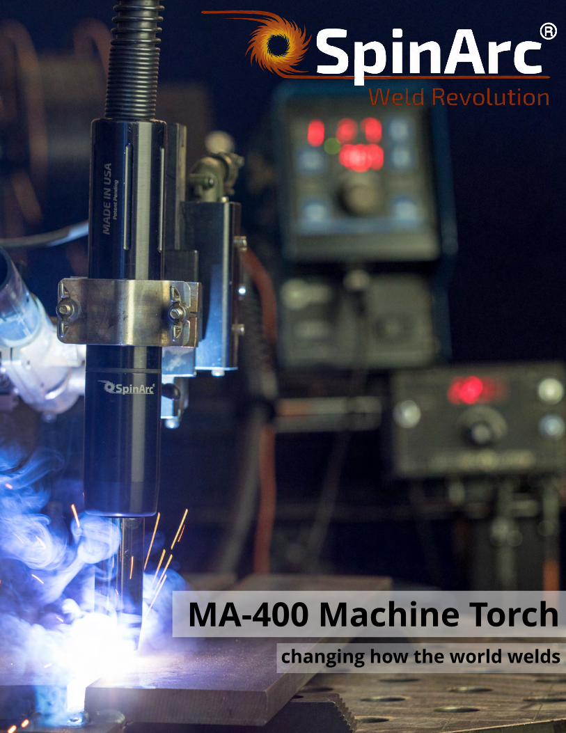
MA-400 Machine Torchchanging how t he wor ld welds

Page 2, MA-400 SpinArc® Brochure, revised 02-07-2018
SpinArc® welding torches use a patented technology that rotates the contact tip in a high-speed, circular motion.
The rotating arc spreads out the heat input and directs the arc energy in a unique pattern.
The process provides good side wall fusion, reduced distortion, increased productivity and the ability to control bead profile and penetration.
Specif icat ions
RATED OUTPUT
Air-Cooled: 300 A, 100% D.C. w/ mixed gas
Water-Cooled Nozzle: 400 A, 100% D.C. w/ mixed gas
SPIN RELATED
Spin Diameter: 1 - 8 mm
Spin Speed: 400 - 5,500 rpm
WELDING DETAILS
Wire Diameters: 0.023 - 1/16 in. (0.6 - 1.6 mm)
Processes: GMAW, GMAW-P, FCAW
Wire Types: Solid, Metal-Core, Flux-Core
Positions: 1G, 2G, 3G, 4G, 5G, 1F, 2F, 3F, 4F
Applications: Plate, Pipe, Fillet Welds, Overlay
ELECTRICAL INPUT 110-240 VAC, 50/60 Hz
COMPLIANCE CE, RoHS Compliant, IP51
IEC/EN 60974-7
What is SpinArc®?
Page 3, MA-400 SpinArc® Brochure, revised 02-07-2018
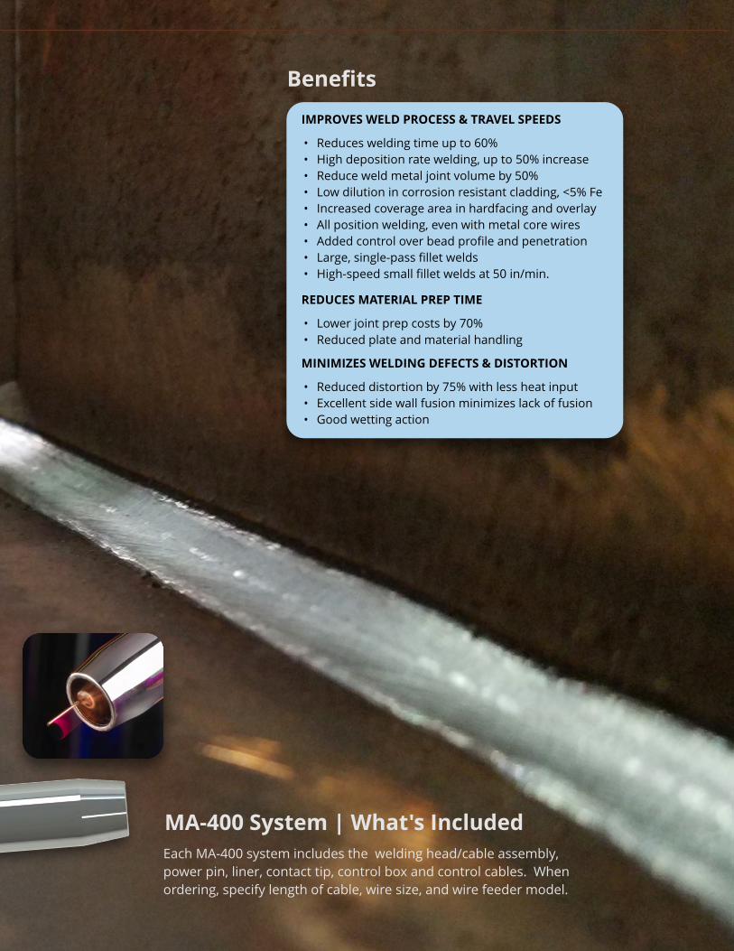
IMPROVES WELD PROCESS & TRAVEL SPEEDS
- Reduces welding time up to 60%- High deposition rate welding, up to 50% increase- Reduce weld metal joint volume by 50%- Low dilution in corrosion resistant cladding, <5% Fe- Increased coverage area in hardfacing and overlay- All position welding, even with metal core wires- Added control over bead profile and penetration- Large, single-pass fillet welds- High-speed small fillet welds at 50 in/min.
REDUCES MATERIAL PREP TIME
- Lower joint prep costs by 70% - Reduced plate and material handling
MINIMIZES WELDING DEFECTS & DISTORTION
- Reduced distortion by 75% with less heat input- Excellent side wall fusion minimizes lack of fusion- Good wetting action
Benef it s
MA-400 Syst em | What 's IncludedEach MA-400 system includes the welding head/cable assembly, power pin, liner, contact tip, control box and control cables. When ordering, specify length of cable, wire size, and wire feeder model.
Page 4, MA-400 SpinArc® Brochure, revised 02-07-2018
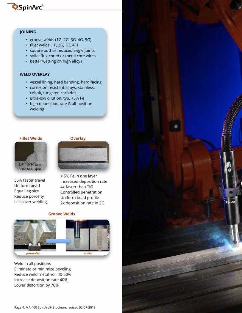
JOINING
- groove welds (1G, 2G, 3G, 4G, 5G)- fillet welds (1F, 2G, 3G, 4F) - square butt or reduced angle joints - solid, flux-cored or metal core wires- better wetting on high alloys
WELD OVERLAY
- vessel lining, hard banding, hard facing- corrosion resistant alloys, stainless,
cobalt, tungsten carbides- ultra-low dilution, typ. <5% Fe- high deposition rate & all-position
welding
55% faster travelUniform bead Equal leg sizeReduce porosityLess over welding
Fil let Welds
Groove Welds
Weld in all positionsEliminate or minimize beveling Reduce weld metal vol. 40-50%Increase deposition rate 40%Lower distortion by 70%
Over lay
< 5% Fe in one layerIncreased deposition rate 4x faster than TIGControlled penetrationUniform bead profile2x deposition rate in 2G
1/8" @ 50 ipm3/16" @ 40 ipm

Page 5, MA-400 SpinArc® Brochure, revised 02-07-2018
STRUCTURALmetal buildingscolumn splicespiling bridges
HEAVY FABRICATIONhard facing & claddinghigh deposition ratehigh-speed filletsreduced bevel groove
OIL & GASsubsea componentspressure vessels storage tanksoffshore rigs
POWER GENERATIONwind towers coal crusher rollsboiler walls and tubesgas turbine rebuilds
SHIP BUILDING weld through primerpanel lines, seamersstiffener weldsbarges
AUTOMOTIVE |TRANSPORTATIONtruck bodies & trailersautomotive framesrail cars & tankers
MAINTENANCE | REPAIR corrosion resistant alloysroll, shaft and prop repairplow blade rebuildingvalve repairhard facing
PIPE | TUBULAR pipe to flangehydraulic cylindersmainline girth weldspipe spool shops
Page 6, MA-400 SpinArc® Brochure, revised 02-07-2018
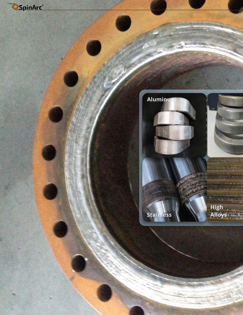
Alum inum St eel
St ainlessHigh Alloys
Page 7, MA-400 SpinArc® Brochure, revised 02-07-2018
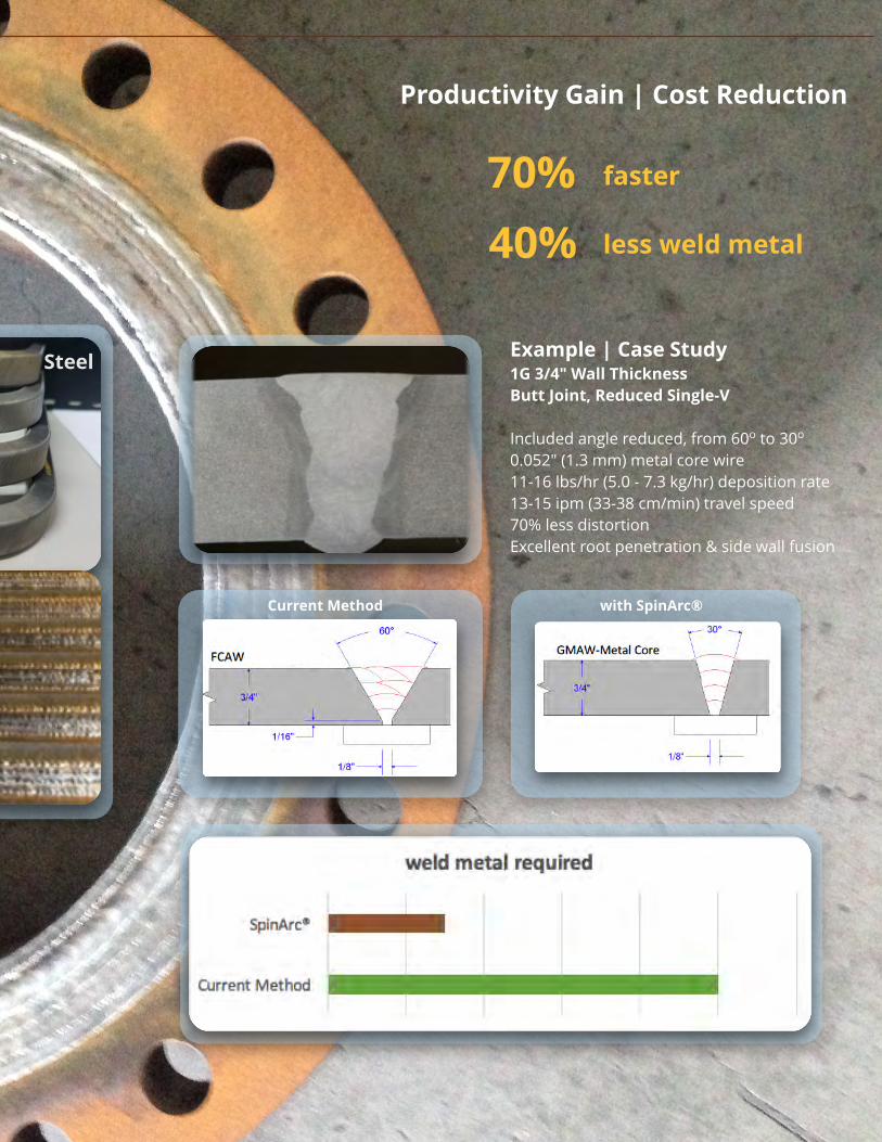
Product ivit y Gain | Cost Reduct ion
Exam ple | Case St udy1G 3/4" Wall ThicknessBut t Joint , Reduced Single-V
Included angle reduced, from 60o to 30o
0.052" (1.3 mm) metal core wire11-16 lbs/hr (5.0 - 7.3 kg/hr) deposition rate13-15 ipm (33-38 cm/min) travel speed70% less distortionExcellent root penetration & side wall fusion
40%
fast er
less weld m et al
70%
St eel
wit h SpinArc®Cur rent Met hod
Page 8, MA-400 SpinArc® Brochure, revised 02-07-2018
Page 9, MA-400 SpinArc® Brochure, revised 02-07-2018
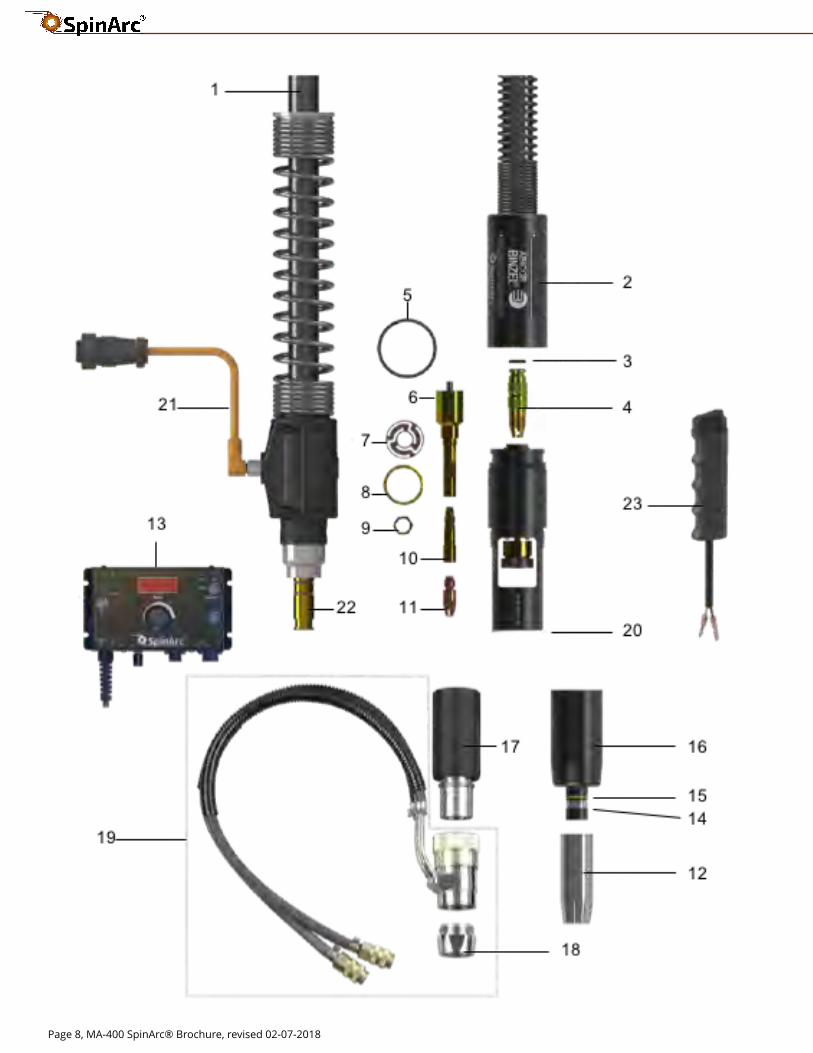
Replacem ent Par t sIt em Descript ion Part #
1 Cable Assembly CA-XX **
2 Upper Cap 1028
3 O-Ring, Power Stud 1037
4 Power Stud 1053
5 O-Ring, Outer Body 1099
6 Spin Shaft Assembly A1554
7 Flexure 1032
8 Flexure Nut, Outer 1034
9 Flexure Nut, Inner 1033
10 Contact Tip Extension See below
11 Contact Tip See below
12 Shielding Gas Nozzle See below
13 Control Box CB-115CE or CB-115CE-R
14 Nozzle Retaining Ring 001.9029
15 O-Ring, Cap 165.9012
16 Cap 1012
* 17 Lower Cap for Water-Cooled Nozzle 1012-WC
* 18 W/ C Nozzle 15/ 16? (24 mm Bore) 979.0054.1
* 19 W/ C Nozzle Assembly complete 979.0049.1
20 Lower Insulator 1007
21 Control Cable See Table Below
22 Power Pin See Table Below
23 Arc Start Trigger Accessory TS-15
* Not Shown Isolated Torch Mount 979.0055.1
Not Shown Flexure Nut Tool 1087
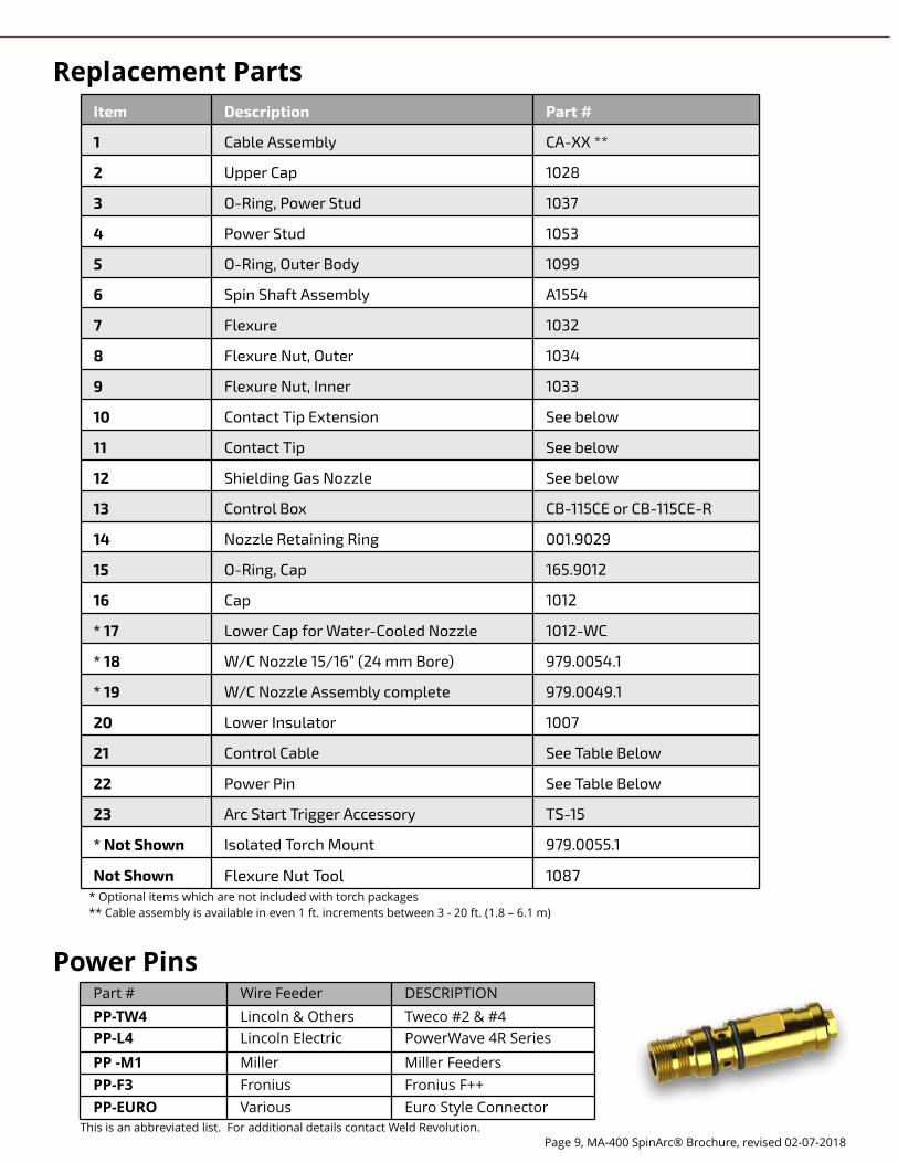
Power Pins Part # Wire Feeder DESCRIPTION
PP-TW4 Lincoln & Others Tweco #2 & #4
PP-L4 Lincoln Electric PowerWave 4R Series
PP -M1 Miller Miller Feeders
PP-F3 Fronius Fronius F++
PP-EURO Various Euro Style ConnectorThis is an abbreviated list. For additional details contact Weld Revolution.
* Optional items which are not included with torch packages* * Cable assembly is available in even 1 ft. increments between 3 - 20 ft. (1.8 ? 6.1 m)
Page 10, MA-400 SpinArc® Brochure, revised 02-07-2018
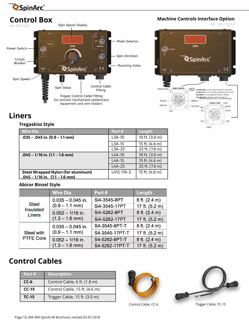
Wire Dia. Part # Length
.035 ? .045 in. (0.9 ? 1.1 mm) L3A-10 10 f t . (3.0 m)
L3A-15 15 f t . (4.6 m) L3A-25 25 f t . (7.6 m)
.045 ? 1/ 16 in. (1.1 ? 1.6 mm) L4A-10 10 f t . (3.0 m) L4A-15 15 f t . (4.6 m) L4A-25 25 f t . (7.6 m)
Steel Wrapped Nylon (for aluminum).045 ? 1/ 16 in. (1.1 ? 1.6 mm)
L415-116-2 15 f t . (4.6 m)
Tregask iss St yle
Abicor Binzel St yle
Liners
Cont rol Box
Cont rol Cables
Par t # Descr ipt ion
CC-6 Control Cable, 6 ft. (1.8 m)
CC-15 Control Cable, 15 ft. (4.6 m)
TC-15 Trigger Cable, 15 ft. (3.0 m)
Control Cable, CC-6 Trigger Cable, TC-15
Machine Cont rols Int er face Opt ionPN: CB-115CE-RPN: CB-115CE
Page 11, MA-400 SpinArc® Brochure, revised 02-07-2018
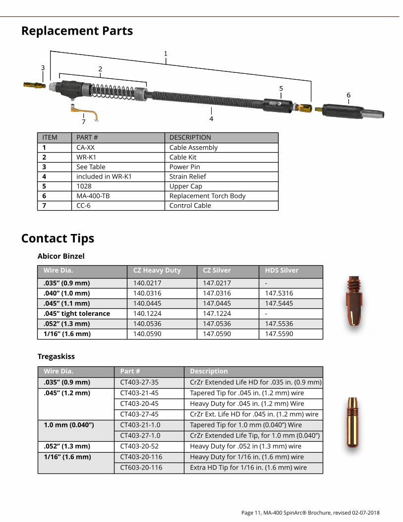
Cont act Tips
Wire Dia. CZ Heavy Dut y CZ Silver HDS Silver
.035? (0.9 m m ) 140.0217 147.0217 -
.040? (1.0 m m ) 140.0316 147.0316 147.5316
.045? (1.1 m m ) 140.0445 147.0445 147.5445
.045? t ight t olerance 140.1224 147.1224 -
.052? (1.3 m m ) 140.0536 147.0536 147.5536
1/16? (1.6 m m ) 140.0590 147.0590 147.5590
Abicor Binzel
Wire Dia. Par t # Descr ipt ion
.035? (0.9 m m ) CT403-27-35 CrZr Extended Life HD for .035 in. (0.9 mm)
.045? (1.2 m m ) CT403-21-45 Tapered Tip for .045 in. (1.2 mm) wire
CT403-20-45 Heavy Duty for .045 in. (1.2 mm) Wire
CT403-27-45 CrZr Ext. Life HD for .045 in. (1.2 mm) wire
1.0 m m (0.040?) CT403-21-1.0 Tapered Tip for 1.0 mm (0.040?) Wire
CT403-27-1.0 CrZr Extended Life Tip, for 1.0 mm (0.040?)
.052? (1.3 m m ) CT403-20-52 Heavy Duty for .052 in (1.3 mm) wire
1/16? (1.6 m m ) CT403-20-116 Heavy Duty for 1/16 in. (1.6 mm) wire
CT603-20-116 Extra HD Tip for 1/16 in. (1.6 mm) wire
Tregask iss
ITEM PART # DESCRIPTION
1 CA-XX Cable Assembly
2 WR-K1 Cable Kit
3 See Table Power Pin
4 included in WR-K1 Strain Relief
5 1028 Upper Cap
6 MA-400-TB Replacement Torch Body
7 CC-6 Control Cable
Replacem ent Par t s
Page 12, MA-400 SpinArc® Brochure, revised 02-07-2018
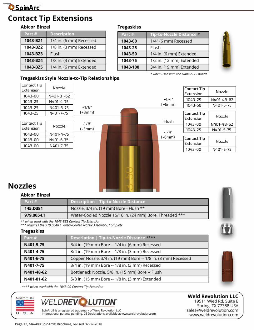
Nozzles
Cont act Tip Ext ensions
Par t # Tip-t o-Nozzle Dist ance *
1043-00 1/4" (6 mm) Recessed
1043-25 Flush
1043-50 1/4 in. (6 mm) Extended
1043-75 1/2 in. (12 mm) Extended
1043-100 3/4 in. (19 mm) Extended
Par t # Descr ipt ion
1043-BZ1 1/4 in. (6 mm) Recessed
1043-BZ2 1/8 in. (3 mm) Recessed
1043-BZ3 Flush
1043-BZ4 1/8 in. (3 mm) Extended
1043-BZ5 1/4 in. (6 mm) Extended
Abicor Binzel Tregask iss
Par t # Descr ipt ion | Tip-t o-Nozzle Dist ance
145.D381 Nozzle, 3/4 in. (19 mm) Bore - Flush * *
979.0054.1 Water-Cooled Nozzle 15/16 in. (24 mm) Bore, Threaded * * *
Abicor Binzel
Par t # Descr ipt ion | Tip-t o-Nozzle Dist ance * * * *
N401-5-75 3/4 in. (19 mm) Bore -- 1/4 in. (6 mm) Recessed
N401-4-75 3/4 in. (19 mm) Bore -- 1/8 in. (3 mm) Recessed
N401-6-75 Copper Nozzle, 3/4 in. (19 mm) Bore -- 1/8 in. (3 mm) Recessed
N401-7-75 3/4 in. (19 mm) Bore -- 1/8 in. (3 mm) Recessed
N401-48-62 Bottleneck Nozzle, 5/8 in. (15 mm) Bore -- Flush
N401-81-62 5/8 in. (15 mm) Bore -- 1/8 in. (3 mm) Extended
Tregask iss
Weld Revolut ion LLC19511 Wied Rd, Suite E
Spring, TX 77388 [email protected]
www.weldrevolution.comSpinArc® is a registered trademark of Weld Revolution LLCInternational patents pending, CE Declarations available at www.weldrevolution.com
* * when used with the 1043-BZ3 Contact Tip Extension* * * requires the 979.0048.1 Water-Cooled Nozzle Assembly, Complete
* when used with the N401-5-75 nozzle
* * * * when used with the 1043-00 Contact Tip Extension
Tregask iss St yle Nozzle-t o-Tip Relat ionships


