1 0 7 6 8 9 3 4 2 5 Page Number Number of Pages Modification Board Series Customer Model MACHINE ROOM CONNECTIONS Serial Number Referance Confirm : 1 18 Draw Date Draw Date First Drawing Project No Form No 12.04.2019 PIT LINE 3X380 V AC MACHINE ROOM DISTRIBUTION PANEL Alarm Button KSL-1 A2 A1 220V AC INTERCOM PHONE Power main switch shall be min. AC-23B Type Supply terminals of rescue system power device output (LP1-LP2) must be passed from main switch contacts (NO). 9 10 QF-1 : Ground Fault Circuit Breaker MSS-1 : Main Switch F1 : Group Circuit Breaker for Main Power F2 : Circuit Breaker for Shaft Lamps F3 : Circuit Breaker for Control Panel Ligting and Car Lihgting FTKR-KL : Ground Fault Circuit Breaker For Car Lighting FTKR-SL : Ground Fault Circuit Breaker For Shaft Lighting SBL-1 : Shaft Lamps Button in Machine Room SBL-2 : Shaft Lamps Button in Pit SL-1..SL-n : Shaft Lighting Lamps KSL-1 : Teleruptor for Shaft Lamps 12.12.2016 H.USTA Hakan USTA F/7.5.5.02.104 ELECTRIC AE-MAESTRO 01 BİLER ASAN.OTO ELEKT. İNŞ.TAŞ.SAN.TİC.LTD.ŞTİ. 93V7101 ŞAHİNLER İNŞAAT 52322 L1 L2 L3 N L1 L2 L3 N LP2 LP1 PE PE 1 2 3 4 5 6 7 8 QF-1 L N PE SOCKET 220V AC 4 3 S-ALM 4 3 SBL-2 4 3 SBL-1 3 4 SL-2 SL-1 B C 220V AC SL-n F2-16A 1 2 3 4 FTKR-KL 30mA (25A) Δ I F3-10A NF 1F 1 2 3 4 FTKR-SL 30mA (25A) Δ I 1 2 3 4 5 6 7 8 MSS-1 40A 1 2 3 4 5 6 7 8 F1 25A MP / 2.0 1 / 2.0 ALM / 11.0 12V+ / 11.0 L1 / 2.0 L2 / 2.0 L3 / 2.0 N / 2.0 LP2 / 2.0 LP1 / 2.0 PE / 2.0 NF / 2.0 1F / 2.0 INT-B / 12.0 INT-C / 12.0
Transcript
10 76 8 93 42 5
Page Number
Number of Pages
Modification Board Series Customer
Model
MACHINE ROOM CONNECTIONSSerial Number
Referance
Confirm : 1
18DrawDate
DrawDate
First DrawingProject NoForm No
12.04.2019
PIT
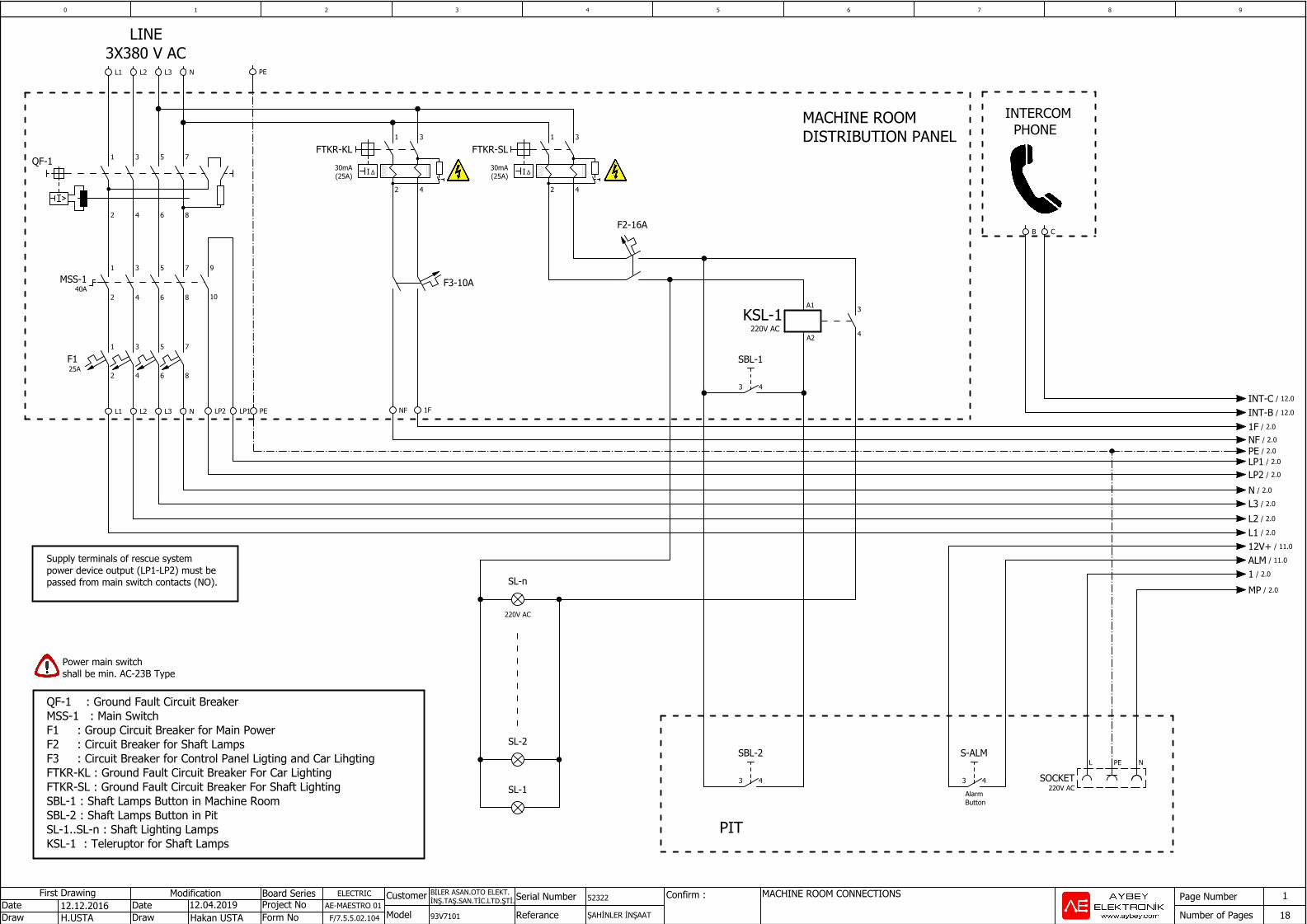
LINE3X380 V AC
MACHINE ROOMDISTRIBUTION PANEL
AlarmButton
KSL-1A2
A1
220V AC
INTERCOM PHONE
Power main switchshall be min. AC-23B Type
Supply terminals of rescue system power device output (LP1-LP2) must bepassed from main switch contacts (NO).
9
10
QF-1 : Ground Fault Circuit BreakerMSS-1 : Main SwitchF1 : Group Circuit Breaker for Main PowerF2 : Circuit Breaker for Shaft LampsF3 : Circuit Breaker for Control Panel Ligting and Car LihgtingFTKR-KL : Ground Fault Circuit Breaker For Car LightingFTKR-SL : Ground Fault Circuit Breaker For Shaft LightingSBL-1 : Shaft Lamps Button in Machine RoomSBL-2 : Shaft Lamps Button in PitSL-1..SL-n : Shaft Lighting LampsKSL-1 : Teleruptor for Shaft Lamps
12.12.2016H.USTA Hakan USTA F/7.5.5.02.104
ELECTRICAE-MAESTRO 01
BİLER ASAN.OTO ELEKT.İNŞ.TAŞ.SAN.TİC.LTD.ŞTİ.
93V7101 ŞAHİNLER İNŞAAT
52322
L1 L2 L3 N
L1 L2 L3 N LP2 LP1 PE
PE
1
2
3
4
5
6
7
8
QF-1
L NPE
SOCKET220V AC
43
S-ALM
43
SBL-2
43
SBL-1
3
4
SL-2
SL-1
B C
220V AC
SL-n
F2-16A
1
2
3
4
FTKR-KL30mA(25A) ΔI
F3-10A
NF 1F
1
2
3
4
FTKR-SL30mA(25A) ΔI
1
2
3
4
5
6
7
8
MSS-140A
1
2
3
4
5
6
7
8
F1 25A
MP / 2.0
1 / 2.0
ALM / 11.0
12V+ / 11.0
L1 / 2.0
L2 / 2.0
L3 / 2.0N / 2.0
LP2 / 2.0LP1 / 2.0PE / 2.0NF / 2.01F / 2.0
INT-B / 12.0
INT-C / 12.0
10 76 8 93 42 5
Page Number
Number of Pages
Modification Board Series Customer
Model
POWER CONNECTIONSSerial Number
Referance
Confirm : 2
18DrawDate
DrawDate
First DrawingProject NoForm No
24.05.2019
5x12V=60V
Battery Group12V 7Ah
- +
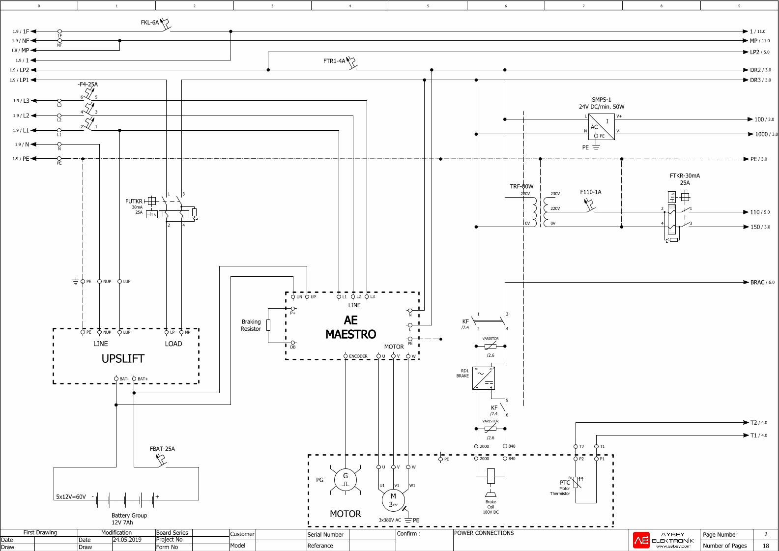
UPSLIFT LOAD LINE
MOTOR
LINE
AEAEAEAEMAESTROMAESTROMAESTROMAESTRO
3x380V AC
MOTOR
AC
N
PE
L1
L2
L3
T1T2
PTCMotor
Thermistor
Θ
P1P2
12
34
FTKR-30mA25A
Δ I
F110-1A
0V 0V
220V
220V 230VTRF-80W
P+
DB
BrakingResistor
BAT+BAT-
NPLPLUPPE NUP
FBAT-25A
LUPPE NUP
1
2
3
4
FUTKR30mA
25A ΔI
PE
L2L1
1F
NF
FTR1-4A
L3
6 5
4 3
2 1
-F4-25A
UN UP
L
N
PE
ENCODER
PG G
PE
U1 V1 W1
3~M
WVU
U V W
2000
2000
RD1BRAKE
ACAC
3
4
VARISTOR
/2.6
1
2KF/7.4
5
6KF/7.4
840
840
BrakeCoil
180V DC
VARISTOR
/2.6
PEN V-
L V+
SMPS-124V DC/min. 50W
I
PE
FKL-6A
N/1.9
PE / 3.0PE/1.9
L1/1.9
L2/1.9
L3/1.9
DR3 / 3.0LP1/1.9
1/1.9
DR2 / 3.0LP2/1.9
T1 / 4.0
T2 / 4.0
150 / 3.0
110 / 5.0
MP/1.9
MP / 11.0NF/1.9
1F/1.9 1 / 11.0
1000 / 3.0
100 / 3.0
LP2 / 5.0
BRAC / 6.0
10 76 8 93 42 5
Page Number
Number of Pages
Modification Board Series Customer
Model
MAINBOARD CONNECTIONSSerial Number
Referance
Confirm : 3
18DrawDate
DrawDate
First DrawingProject NoForm No
27.03.2019
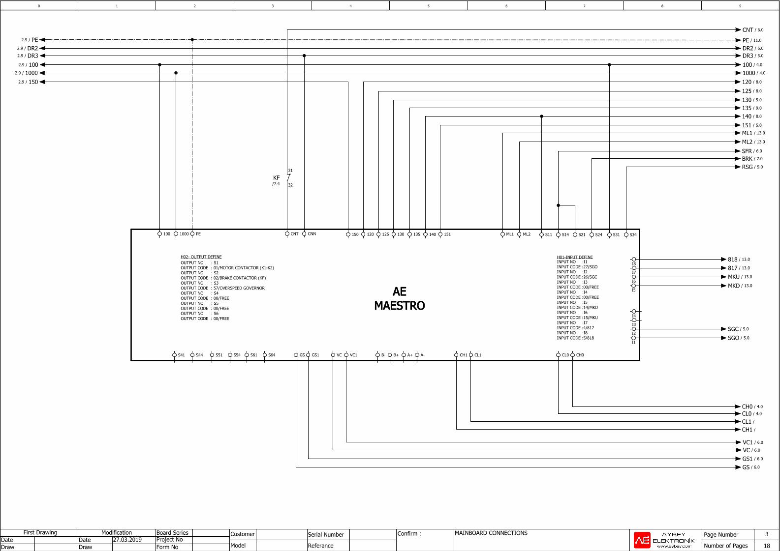
INPUT NO :I1INPUT CODE :27/SGOINPUT NO :I2INPUT CODE :26/SGCINPUT NO :I3INPUT CODE :00/FREEINPUT NO :I4INPUT CODE :00/FREEINPUT NO :I5INPUT CODE :14/MKDINPUT NO :I6INPUT CODE :15/MKUINPUT NO :I7INPUT CODE :4/817INPUT NO :I8INPUT CODE :5/818
H01-INPUT DEFINEH02- OUTPUT DEFINEOUTPUT NO : S1OUTPUT CODE : 01/MOTOR CONTACTOR (K1-K2)OUTPUT NO : S2OUTPUT CODE : 02/BRAKE CONTACTOR (KF)OUTPUT NO : S3OUTPUT CODE : 57/OVERSPEED GOVERNOROUTPUT NO : S4OUTPUT CODE : 00/FREEOUTPUT NO : S5OUTPUT CODE : 00/FREEOUTPUT NO : S6OUTPUT CODE : 00/FREE
AEAEAEAEMAESTROMAESTROMAESTROMAESTRO
ML1 ML2
I8
I7
I6
I5
S11 S14 S21 S24 S31 S34
I4
I3
I2
I1
CL0 CH0CH1S44S41 S54S51 S61 S64 CL1
100 1000 CNT CNN
31
32KF/7.4
PE
GS1GS VC VC1 B+B- A+ A-
120 125 130 140 151135150
DR3/2.9
100/2.9
150/2.9
PE/2.9
1000/2.9
CL0 / 4.0CH0 / 4.0
DR2/2.9PE / 11.0
DR3 / 5.0
100 / 4.0
1000 / 4.0
818 / 13.0
817 / 13.0
MKU / 13.0
MKD / 13.0
125 / 8.0
130 / 5.0
140 / 8.0
151 / 5.0
ML1 / 13.0
ML2 / 13.0
135 / 9.0
120 / 8.0
SFR / 6.0
BRK / 7.0
CH1 /CL1 /
SGO / 5.0
SGC / 5.0
RSG / 5.0
DR2 / 6.0
VC1 / 6.0
VC / 6.0
GS1 / 6.0
GS / 6.0
CNT / 6.0
10 76 8 93 42 5
Page Number
Number of Pages
Modification Board Series Customer
Model
TERMINAL CONNECTIONSSerial Number
Referance
Confirm : 4
18DrawDate
DrawDate
First DrawingProject NoForm No
27.03.2019
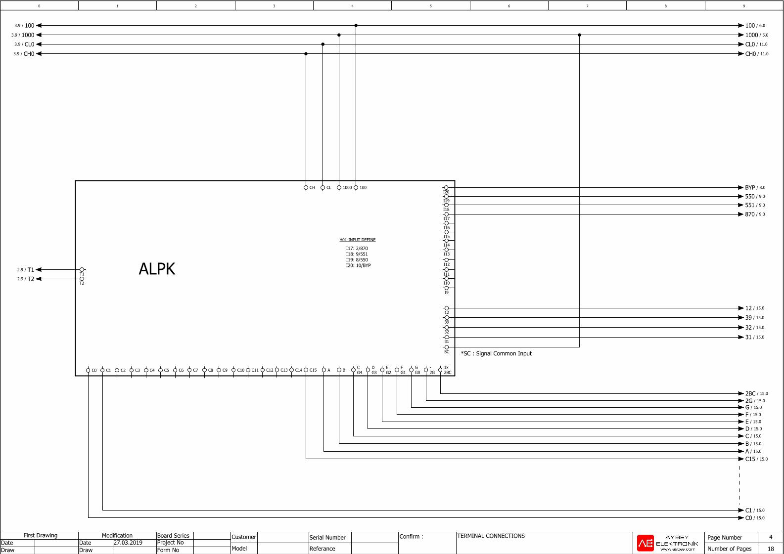
H01-INPUT DEFINE
*SC : Signal Common Input
I17: 2/870I18: 9/551I19: 8/550I20: 10/BYPALPK
C15C14C13C12C11C10C9C8C7C6C5C4C3C2C0 C1
12
39
32
31
SC
A B CG4
DG3
EG2
FG1
GG0
-2G
1x2BC
I20
I19
I18
I17
I16
I15
I14
I13
I12
I11
I10
I9
1000 100CH CL
T1
T2
100/3.9 100 / 6.0
1000/3.9 1000 / 5.0
CH0/3.9
CL0/3.9
CH0 / 11.0
CL0 / 11.0
2BC / 15.0
2G / 15.0G / 15.0
F / 15.0
E / 15.0
D / 15.0
C / 15.0
B / 15.0
A / 15.0
C0 / 15.0C1 / 15.0
12 / 15.0
39 / 15.0
32 / 15.0
31 / 15.0
C15 / 15.0
BYP / 8.0
550 / 9.0
551 / 9.0
870 / 9.0
T1/2.9
T2/2.9
10 76 8 93 42 5
Page Number
Number of Pages
Modification Board Series Customer
Model
OVERSPEED GOVERNOR A3 CONNECTIONSSerial Number
Referance
Confirm : 5
18DrawDate
DrawDate
First DrawingProject NoForm No
27.03.2019
CLAMPINGCONTACTMONITORING
OVERSPEED GOVERNOR
MRS-A3: OSG Clamping coil activation switch for manual rescue operation.
SGDSGDSGDSGD
AC3SFL151 AC2 AC1 RSG SGC 1000 SG- SG+ SGO SGO
1000
A1 A2
OSGCLAMPING
COIL190V DC
SG-SG+
SG+ SG- SGO
21
43
MRS-A3
FOSG-2ARSG/3.9
130/3.9
151/3.9
110/2.9
SGC/3.9
SGO/3.9
1000 / 6.01000/4.9
DR3/3.9 DR3 / 17.0
151 / 6.0
130 / 8.0
110 / 9.0
LP2/2.9
AC3 / 6.0
AC2 / 6.0
10 76 8 93 42 5
Page Number
Number of Pages
Modification Board Series Customer
Model
SER BOARD CONNECTIONSSerial Number
Referance
Confirm : 6
18DrawDate
DrawDate
First DrawingProject NoForm No
27.03.2019
SERSERSERSERBOARDBOARDBOARDBOARD
100 1000 GS GS1 VC VC1
41
42SFR1
/6.5
SF11 SF12
11
14SFR1
/6.5
R1-11 R1-14 R2-11 R2-14
11
14SFR2
/6.5
SFR 151
21
24SFR1
/6.5
R1-21 R1-24 R2-21 R2-24
21
24SFR2
/6.5
31
34SFR1
/6.5
31
34SFR2
/6.5
41
42SFR2
/6.5
A1
A2SFR2
1411 /6.32421 /6.43431 /6.64241 /6.1
A1
A2SFR1
1411 /6.22421 /6.33431 /6.74241 /6.1
1000 / 8.01000/5.9
100/4.9 100 / 11.0
151/5.9 151 / 7.0
SFR/3.9
AC3/5.9
CNT/3.9
DR2/3.9 DR2 / 17.0
GS/3.9
GS1/3.9
VC/3.9
VC1/3.9
AC2/5.9
BRAC/2.9
10 76 8 93 42 5
Page Number
Number of Pages
Modification Board Series Customer
Model
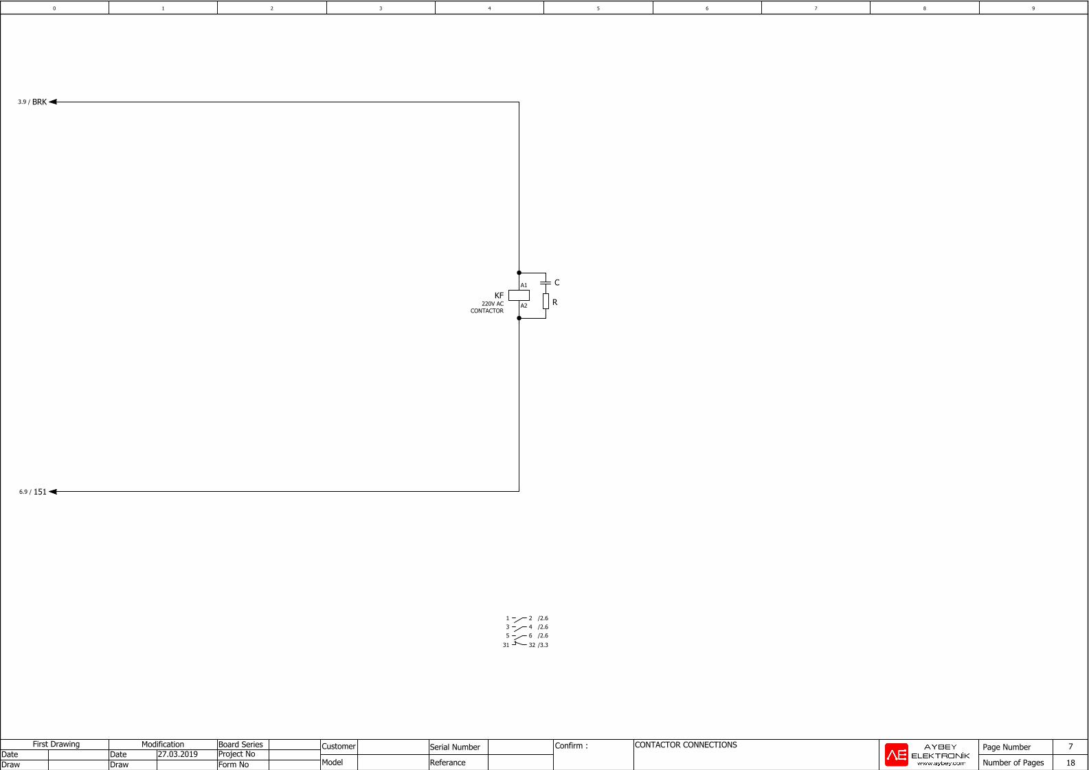
CONTACTOR CONNECTIONSSerial Number
Referance
Confirm : 7
18DrawDate
DrawDate
First DrawingProject NoForm No
27.03.2019
C
R
A1
A2KF
220V ACCONTACTOR
21 /2.643 /2.665 /2.63231 /3.3
BRK/3.9
151/6.9
10 76 8 93 42 5
Page Number
Number of Pages
Modification Board Series Customer
Model
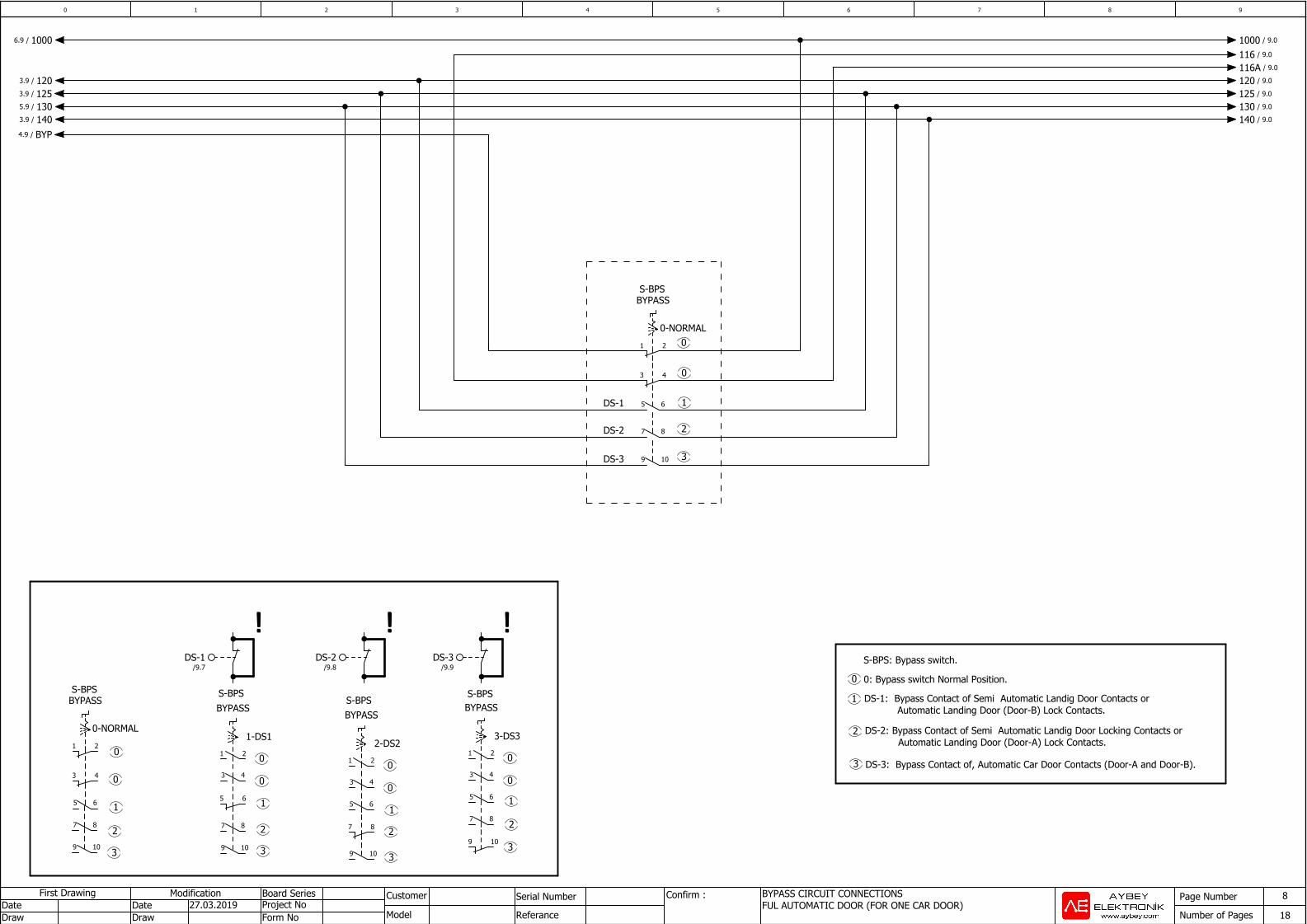
BYPASS CIRCUIT CONNECTIONSFUL AUTOMATIC DOOR (FOR ONE CAR DOOR)
Serial Number
Referance
Confirm : 8
18DrawDate
DrawDate
First DrawingProject NoForm No
27.03.2019
0
1
2
3
3
2
1
0
DS-2: Bypass Contact of Semi Automatic Landig Door Locking Contacts or Automatic Landing Door (Door-A) Lock Contacts.
DS-3: Bypass Contact of, Automatic Car Door Contacts (Door-A and Door-B).
0: Bypass switch Normal Position.
00-NORMAL
DS-1
DS-2
DS-3
S-BPS
!!!!!!!!!!!!S-BPS: Bypass switch.
0
1
2
3
0
0-NORMAL
S-BPS
0
1
2
3
0
1-DS1
S-BPSS-BPS S-BPS
1
2
3
0
0
2-DS2
1
2
3
0
0
3-DS3
DS-1: Bypass Contact of Semi Automatic Landig Door Contacts or Automatic Landing Door (Door-B) Lock Contacts.
1 2
BYPASS
3 4
5 6
7 8
9 10
DS-3/9.9
DS-2/9.8
DS-1/9.7
1 2
BYPASS
3 4
5 6
7 8
9 10
5 6
3 4
7 8
9 10
1 2
BYPASS
5 6
9 10
7 8
3 4
1 2
BYPASS
7 8
5 6
9 10
3 4
1 2
BYPASS
1000 / 9.01000/6.9
116 / 9.0
116A / 9.0
120/3.9 120 / 9.0
125/3.9 125 / 9.0
130/5.9 130 / 9.0
140/3.9 140 / 9.0
BYP/4.9
10 76 8 93 42 5
Page Number
Number of Pages
Modification Board Series Customer
Model
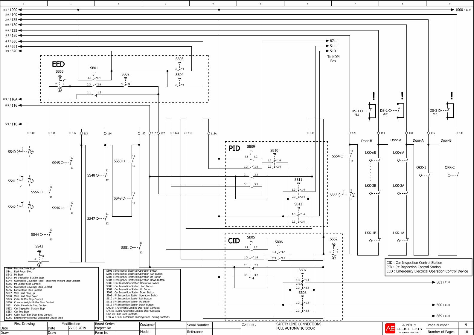
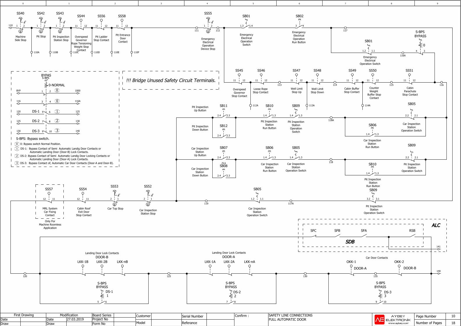
SAFETY LINE CONNECTIONSFULL AUTOMATIC DOOR
Serial Number
Referance
Confirm : 9
18DrawDate
DrawDate
First DrawingProject NoForm No
27.03.2019
CIDCIDCIDCID
PIDPIDPIDPID
b
!!!! !!!! !!!!
Door-BDoor-ADoor-ADoor-B
EEDEEDEEDEED
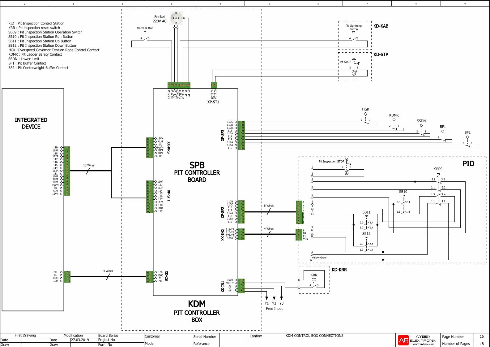
CID : Car Inspection Control StationPID : Pit Inspection Control StationEED : Emergency Electrical Operation Control DeviceSB01 : Emergency Electrical Operation Switch
SB02 : Emergency Electrical Operation Run ButtonSB03 : Emergency Electrical Operation Up ButtonSB04 : Emergency Electrical Operation Down ButtonSB05 : Car Inspection Station Operation SwitchSB06 : Car Inspection Station Run ButtonSB07 : Car Inspection Station Up ButtonSB08 : Car Inspection Station Down ButtonSB09 : Pit Inspection Station Operation SwitchSB10 : Pit Inspection Station Run ButtonSB11 : Pit Inspection Station Up ButtonSB12 : Pit Inspection Station Down ButtonLKK-xx : Automatic Landing Door Lock ContactsLFK-xx : Semi Automatic Landing Door ContactsOKK-xx : Car Door ContactsLDK-xx : Semi Automatic Landing Door Locking Contacts
SS40 : Machine Side StopSS41 : Reel Room Stop SS42 : Pit StopSS43 : Pit Inspection Station StopSS44 : Overspeed Governor Rope Tensioning Weight Stop ContactSS56 : Pit Ladder Stop ContactSS45 : Overspeed Governor Stop ContactSS46 : Loose Rope Stop Contact SS47 : Well Limit Stop UpSS48 : Well Limit Stop DownSS49 : Cabin Buffer Stop ContactSS50 : Counter Weight Buffer Stop ContactSS51 : Cabin Parachute Stop ContactSS52 : Car Inspection Station StopSS53 : Car Top StopSS54 : Cabin Roof Exit Door Stop ContactSS55 : Emergency Electrical Operation Device Stop
To KDMBox
11
12SS51
21
SS52LKK-1B
12
11SS44
12
SS43
LKK-1A
110 111 112 140113 114 116
DS-1/8.1
120
1
2SS40
1
2SS41
1
2SS42
12
11SS54
1.41.3
SB11
12
11SS45
11
12SS49
11
12SS50
2
1SS53
115 118A
1.41.3
2.22.1
1.21.1
SB09
3.23.1
130 135
LKK-2B
LKK-nB
125
DS-2/8.2
11
12SS47
11
12SS48
DS-3/8.3
LKK-2A
LKK-nA
2.42.3
1.21.1
43
SB03
1.41.3
SB01
43
SB02
12
SS55
43
SB04
12
11SS56
12
11SS46
OKK-1 OKK-2
1.41.3
SB12
2.42.3
2.42.3
117 117A 118
1.41.3
SB10
2.42.3
119
2.22.1
3.23.1
1.41.3
1.21.1
SB05
2.42.3
1.41.3/10.4
SB07
1.41.3
SB08
2.42.3
2.42.3
1.41.3
SB06
501 / 11.0
1000/8.9
135/3.9
140/8.9
120/8.9
130/8.9
1000 / 11.0
125/8.9
551/4.9
550/4.9
870/4.9
110/5.9
116/8.9
116A/8.9
500 / 11.0
869 / 11.0
510 /
511 /
871 /
10 76 8 93 42 5
Page Number
Number of Pages
Modification Board Series Customer
Model
SAFETY LINE CONNECTIONSFULL AUTOMATIC DOOR
Serial Number
Referance
Confirm : 10
18DrawDate
DrawDate
First DrawingProject NoForm No
27.03.2019
Landing Door Lock Contacts
SDBSDBSDBSDB
ALCALCALCALC
S-BPS
DS-11
S-BPS S-BPS
DS-22
DS-33
DOOR-B
DOOR-A
Pit InspectionStation
Operation SwitchCar Inspection
StationOperation Switch
SB09SB05
Car Door Contacts
DOOR-A
Landing Door Lock Contacts
OverspeedGovernor
Stop Contact
Loose Rope Stop Contact
Well LimitStop Up
Well LimitStop Down
Cabin BufferStop Contact
CounterWeight
Buffer StopContact
CabinParachute
Stop Contact
SB05
SB09Car Inspection
Station Up Button
Car InspectionStation
Down Button
SB10 Pit InspectionStation
Operation Switch
Car InspectionStation
Operation Switch
EmergencyElectricalOperation
Switch
EmergencyElectricalOperation
Run Button
EmergencyElectrical
Operation Switch
S-BPS
0
Pit Inspection Station
Run Button
EmergencyElectricalOperation
Device Stop
Cabin RoofExit Door
Stop Contact
Car InspectionStation Stop
Car Top StopMRL SystemCar FixingContact
MachineSide Stop
Pit Stop Pit InspectionStation Stop
Pit LadderStop Contact
Pit EntranceDoor
Contact
0
1
2
3
00-NORMAL
S-BPS
DS-1
DS-2
DS-3
S-BPS: Bypass switch.0: Bypass switch Normal Position.0
1 DS-1: Bypass Contact of Semi Automatic Landig Door Contacts or Automatic Landing Door (Door-B) Lock Contacts.
2 DS-2: Bypass Contact of Semi Automatic Landig Door Locking Contacts or Automatic Landing Door (Door-A) Lock Contacts.
3 DS-3: Bypass Contact of, Automatic Car Door Contacts (Door-A and Door-B).
!!! Bridge Unused Safety Circuit Terminals.
Only ForMachine Roomless
Application
SB06Pit InspectionDown Button
Pit InspectionStation
OperationSwitch
Car InspectionStation
Run Button
Car InspectionStation
Operation Switch
Pit InspectionUp Button
Pit Inspection Station
Run Button
Car InspectionStation
Run Button
OverspeedGovernor
Rope TensioningWeight Stop
Contact
DOOR-B
87
BYPASS
125
140
SFC SFB RSBSFA
141
120
OKK-2LKK-1A LKK-2A LKK-nALKK-1B LKK-2B LKK-nB
65
BYPASS
117A
1.11.2
119
3.13.2
130
OKK-1
135
109
BYPASS
1211
SS45
1211
SS46
113
1211
SS47
1211
SS48
114
1211
SS49
1211
SS50
115
1211
SS51
116
2.32.4
/9.6
SB07
118
1.31.4
SB05
2.12.2
1.41.3
SB01
117
43
SB02
34
BYPASS
116A
1.11.2
SB01
1.31.42.32.4
SB08
112
21
SS55
111
1112
SS54
12
SS52
12
SS53
1112
SS57
110 21
SS40
21
SS42
21
SS43
1211
SS44
110A 110B 110C 110D
1211
SS56
110E
1211
SS58
110F
1 2
BYPAS
3 4
5 6
7 8
9 10
1000
116A
125
130
140
BYP
120
116
125
130
113A 114A112A
118A
1.31.4
SB09
2.12.2
1.31.4
2.32.4
SB11
2.32.4
SB12
1.31.4
SB10
1.31.4
SB06
10 76 8 93 42 5
Page Number
Number of Pages
Modification Board Series Customer
Model
INSPECTION BOX CONNECTIONSSerial Number
Referance
Confirm : 11
18DrawDate
DrawDate
First DrawingProject NoForm No
27.03.2019
CabinCALLS
I-BUTTONIB+ IB- N12N9 N11N10
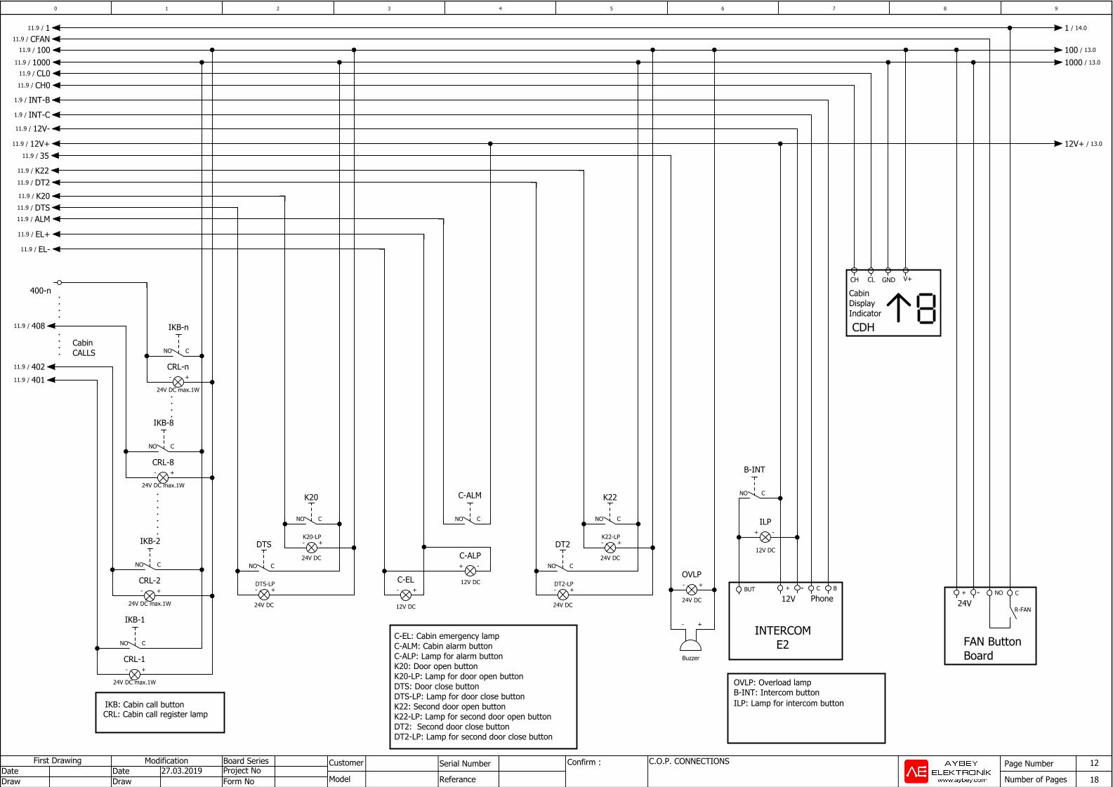
C-OVL: Cabin overload contactDTS-LP: Lamp for door close button DTS: Door close buttonK20-LP: Lamp door open buttonK20: Door open button
CT-ALM: Car top alarm buttonCT-EL: Car top emergency lamp
C-EL: Cabin emergency lampC-ALM: Cabin alarm buttonC-ALP: Lamp for alarm buttonK20: Door open button K20-LP: Lamp for door open button DTS: Door close buttonDTS-LP: Lamp for door close button K22: Second door open button K22-LP: Lamp for second door open button DT2: Second door close buttonDT2-LP: Lamp for second door close button
BC+BUT
+ -
12V DC
ILP
CNO+
R-FAN
- +
Buzzer
- +
24V DC
OVLP- +
12V DC
C-EL
NO C
K22
- +
NO C
B-INT
NO C
C-ALM
+ -C-ALP
- +
24V DC max.1W
CRL-1
NO C
IKB-1
- +
24V DC max.1W
CRL-2
NO C
IKB-2
- +
24V DC max.1W
CRL-8
NO C
IKB-8
NO C
IKB-n
- +
24V DC max.1W
CRL-n
NO C
DT2
- +
NO C
K20
- +
NO C
DTS
- +
1000/11.9
100/11.9CFAN/11.9
1000 / 13.0
100 / 13.0
1/11.9 1 / 14.0
35/11.9
402/11.9
401/11.9
408/11.9
CH0/11.9
CL0/11.9
INT-C/1.9
INT-B/1.9
12V-/11.9
12V+/11.9 12V+ / 13.0
DT2/11.9
ALM/11.9
EL+/11.9
EL-/11.9
DTS/11.9
K20/11.9
K22/11.9
10 76 8 93 42 5
Page Number
Number of Pages
Modification Board Series Customer
Model
MAGNETIC SWITCH CONNECTIONSSerial Number
Referance
Confirm : 13
18DrawDate
DrawDate
First DrawingProject NoForm No
27.03.2019
MKU818/KSR2
817/KSR1
MKD ML2ML1
Roller Switch OrBi-Stable Magnetic Switch
Roller Switch OrBi-Stable Magnetic Switch
Mono-StableMagnetic Switch
Mono-StableMagnetic Switch
Mono-StableMagnetic Switch
Mono-StableMagnetic Switch
MKD 1000818 10001000817 MKU 1000
ML1 MLC
D11N4007
D21N4007
ML2
100 / 14.0
1000/12.9
100/12.9
ML1/3.9
MKU/3.9
MKD/3.9
818/3.9
817/3.9
ML2/3.9
1000 / 14.0
ML1 / 14.0
ML2 / 14.0
12V+/12.9 12V+ / 14.0
10 76 8 93 42 5
Page Number
Number of Pages
Modification Board Series Customer
Model
CONTROL PANEL LAMPSerial Number
Referance
Confirm : 14
18DrawDate
DrawDate
First DrawingProject NoForm No
27.03.2019
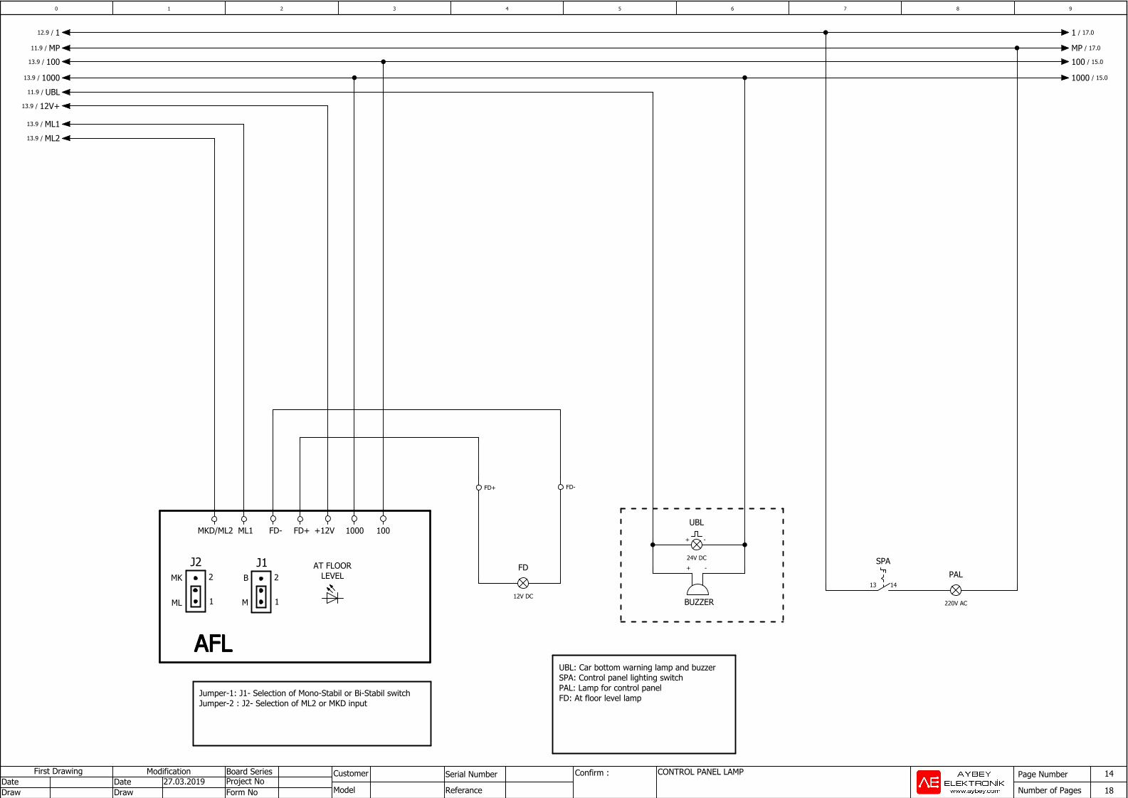
UBL: Car bottom warning lamp and buzzerSPA: Control panel lighting switchPAL: Lamp for control panelFD: At floor level lamp
BUZZER
AFLAFLAFLAFL
FD+ +12V 1000 100FD-ML1MKD/ML2
J12
1
B
M
MK
ML
2
1
J2
Jumper-1: J1- Selection of Mono-Stabil or Bi-Stabil switchJumper-2 : J2- Selection of ML2 or MKD input