18
Version 1.1 Released 06/01/08 14518 County Road 7240 Newburg, MO 65550 www.machmotion.com MachMotion IO6 Breakout Board Manual (with Parallel Port)
| Date post: | 08-May-2018 |
| Category: |
Documents |
| Upload: | duongtuong |
| View: | 230 times |
| Download: | 1 times |

Version 1.1 Released 06/01/08 14518 County Road 7240 Newburg, MO 65550
www.machmotion.com
MachMotion IO6 Breakout Board Manual
(with Parallel Port)
1
**************WARNING************** Improper installation of this motion control interface can cause DEATH, INJURY or serious PROPERTY DAMAGE. Do not attempt to install this board unless you are a properly quali-fied electrical engineer and system integrator. Not every detail of the installation is in-cluded here. A familiarity with electronic circuits, power circuits, and the MACH3 control is a pre-requisite to knowing how to install or use this equipment.
**************WARNING*************

IO6 General Description: Pg 4
Use of this manual: Pg 4
IO6 System Requirements: Pg 4
Description of the interface assemblies:
1. Charge Pump Circuit Pg 5
3. Digital (Pulse and Direction ) interface for 6 axis motion control
Pg 6
3. Differential Step and Direction interface Pg 6
4. Single Ended (Non-differential) Step and Direction inter-face
Pg 7
6. IO6 CW and CCW relay outputs Pg 8
7. IO6 Analog Spindle voltage output: Pg 8
8. Configuring the 0-10 volt Analog Output: Pg 8
9. IO6 Inputs for measuring Spindle RPM: Pg 9
10. Mixed assortment of digital I/O interfaces: Pg 11
11. Opto-isolated digital input terminals: Pg 11
12. Error Input: Pg 12
13. Dual Purpose opto-isolated inputs: Pg 12
17. Relay inputs and outputs: Pg 12
Relay Input Configuration Pg 15
Relay Out-put Configuration Pg 16
Input Circuits Pg 17
Parallel Port Pin-outs Pg 18
Mod-Jack Pin-outs Pg 19
Table of Contents

MachMotion IO6 Layout
3
Figure 1
Output port# 2 pin 17 Enable output (+5v)
6 Differential Mod Jack Servo Drive Interface
2 Spindle Mod Jacks
Dip Switches
6 Axis Step & Direction 10 Opto-Isolated Inputs Relay Bank Assembly
Analog 0-10v Fine tuning port
Spindle Index Pulse
Spindle Analog 0-10v
Spindle CW
Spindle CCW
8 Relay Inputs or Outputs
+5v input power
+12v Input Power
Charge pump output bare contacts
External Power for drive enable (EX-EN)
5 4 3 2 1
Parallel Port 1 Parallel Port 2
Auxiliary Terminal Block
Primary Terminal Block
8 Mod
4
IO6 General Description: MachMotion’s IO6 Breakout Board provides a flexible, plug-in-play interface and functions for CNC Controls using PC Based Parallel Port Control Software. Cabling to the servo drives, and spindle relay outputs employ RJ45 mod jack connectors and Phoenix screw ter-minals to ad flexibility. All other connections to the IO6 board are made through Phoenix screw terminals. Features:
• Digital differential and single ended TTL (Pulse and Direction) interfaces for mo-tion control for up to six axis.
• Opto-isolated Outputs. • Relay based I/O. • Complete spindle speed control circuitry. • Charge Pump safety circuit integrated to control all outputs. • Total of 34 I/O
Input & Output List:
• 12 Outputs generally used for step and direction outputs for 6 axis. If less than six axis are to be controlled, some of these 12 outputs can be used for general purpose outputs.
• 10 Inputs (1 Is Typically used for Spindle Encoder Input) • 8 2 Amp Relay I/O’s which can be configured as either inputs or outputs. • 2 Spindle Relay Outputs • 1 Analog Output 0-10V • 1 Charge Pump Output
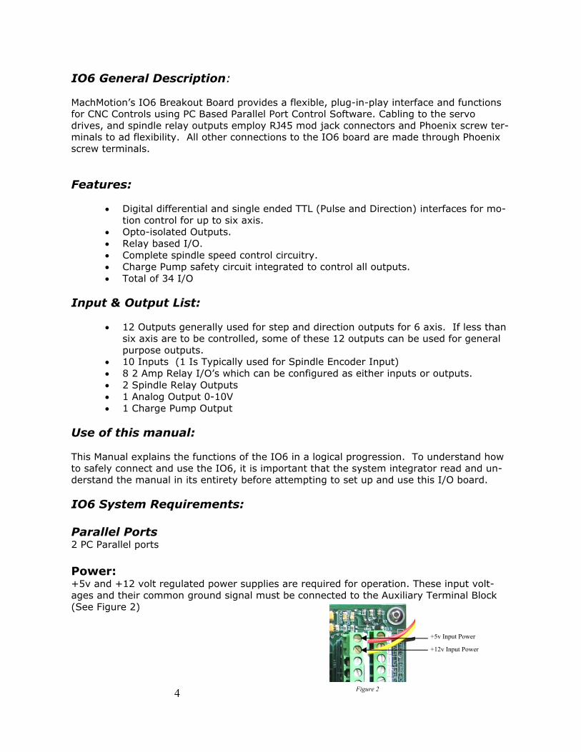
Use of this manual: This Manual explains the functions of the IO6 in a logical progression. To understand how to safely connect and use the IO6, it is important that the system integrator read and un-derstand the manual in its entirety before attempting to set up and use this I/O board. IO6 System Requirements: Parallel Ports 2 PC Parallel ports Power: +5v and +12 volt regulated power supplies are required for operation. These input volt-ages and their common ground signal must be connected to the Auxiliary Terminal Block (See Figure 2)
+5v Input Power
+12v Input Power
Figure 2

Description of the interface assemblies:
1. Charge Pump Circuit: When there is no E-stop condition and the Mach3 software based control is running properly, Mach3 outputs a steady pulse stream to the IO6 breakout board. The IO6 receives this pulse stream and sends an enable signal to every axis mod jack con-nector, on mod jack pin #4. It also enables all outputs of the IO6. If this pulse stream is interrupted, the IO6 will correspondingly disable all outputs from the IO6. This safety circuit prevents spurious outputs from the PC from producing unex-pected results. The Charge pump circuit also energizes a relay that provides a pair of bare relay contacts and a +5 volt Enable signal for system integrators to use to implement other safety measures. These phoenix terminals are located on the Auxiliary Termi-nal Block. See Figure #3. The Charge pump input can be over-ridden by switching dip switch # 2 to the “closed” position. See Figure #4. When the charge pump is over-ridden you can ac-cess Port#2 Pin#17 on the Auxiliary Terminal Block. See Figure #3. This removes the safety provision of the system, thus, a machine must not be operated with the charge pump disabled. This provision is only made available for the use of the sys-tems integrator’s use in setup or troubleshooting.
**************WARNING**************
Use of the IO6 in a machine application with the Charge pump disabled is forbidden. Com-puter based controls running the Windows operating system may encounter unexpected interruptions due to outside influences and computer failures. The Charge pump circuit is a safeguard against these occurrences. Disabling it can allow for DEATH, INJURY or seri-ous PROPERTY DAMAGE.
**************WARNING**************
5
5 4 3 2 1
Opened
Closed
Figure 4
Charge pump output bare relay contacts (CP/CP)
Charge pump enable output (+5v) (EN/GND)
Auxiliary Terminal Block
Figure 3
Output port# 2 pin 17 (17/GND)

6
Figure 5
Axis 2
Axis 1
Axis 4
Axis 3 Axis 5
Axis 6 Spindle Encoder
Spindle Control
3. Digital (Pulse and Direction ) interface for 6 axis motion Control.
The IO6 breakout board provides differential and single ended step and direction both of which may be employed at the same time.
Differential Step and Direction interface: The first 6 jacks of the 8 jack module provide differential step and direction outputs for servo drives. The differential interface provides common mode noise rejection. This interface requires the use servo drives that expect a differential input or differ-ential adapters connected near the servo drives. Modular Jack for Axis 1 is located on the bottom row of jacks, closest to Parallel Port 1. See Figure #5. The pin-out for each of these six mod jacks are: 1. Optional TTL output from servo drive, inputs to the control. These pins connect
to parallel port 1 input pins 11, 12, 13, and 15 for axis 1-4 respectively and par-allel port 2 input pins 10 and 11 for axis 5 and 6 respectively.
2. Drive error signal (Hard wired to opto-coupled circuit connected to input pin 10 of the PC port).
3. Direction 4. Drive Enable (5v= enable). Normally, the Enable signal is 5 volts. This is se-
lected through the “closed” or “ON” setting of DIP switch # 1. If this DIP switch is set to “open” an external supply with a different voltage can be connected to the phoenix screw terminal connector labeled EX-EN and GND. See Figure #6 & 7 The enable signal will be active whenever the Charge Pump circuit makes all circuits on the IO6 active. Warning! If an external voltage is connected to terminal EX-EN without opening DIP switch #1, the IO6 will likely be damaged.
5. GND 6. Direction/ 7. Step 8. Step/ See pin-out chart on Page # 19
5 4 3 2 1
External Drive Enable Opened
Internal Drive Enable Closed “ON”
Figure 6
External Power for drive enable (EX-EN)
Figure 7

7
Direction Row 2,4,6,8,14
Step Row 3,5,7,9,16,17
Ground
Figure 8
2 4 6 8 14 1 3 5 7 9 16 17 GND GND GND GND GND GND
PC Parallel Port #1 Pin-outs
Step Row
Direction Row
**************WARNING************** All Servo drive faults or errors should be connected together so that a failure in one drive shuts down every servo drive at the same time. Failure to configure the Servo Drives in this manner can cause DEATH, INJURY or serious PROPERTY DAMAGE. Do not install drives that do not share the same fault line.
**************WARNING**************
**************CAUTION**************
Be sure DIP switch 1 is set to “open” if an external supply voltage is used to en-able the Servo drives (See Page 6 Figure #6). Damage to the IO6 or power sup-ply will result if this caution is not taken.
**************CAUTION**************
4. Single Ended (Non-differential) Step and Direction interface: The Primary Terminal Block has six phoenix screw terminal connectors for single ended (5v TTL) step and direction control signal access for connection to servo drives. The labeling below the six green phoenix terminal block indicates the corresponding PC parallel port pin that is interfaced by the terminal. For example, terminals la-beled 2, 4, 6, 8, 14, and 1 are to be configured as direction outputs in the Mach3 configuration table, for axis 1-6 respectively. Terminals 3,5,7,9,16, and 17 are to be configured as step outputs for axis 1-6 respectively. The Ground terminals for these signals are also marked on the circuit board.
8
5. Spindle Control Overview:
The IO6 controls the spindle in this way: The machine operator manually sets the spindle speed on the Mach3 control panel display or it is set via the G-code file. Then either the appropriate M-code or the operator turns on the spindle. The hard-ware control sequence is as follows: The Mach3 control turns on either a CW or CCW relay. Then the IO6 sends an appropriate 0-10 volt analog signal out to the Variable Frequency Drive (VFD) which controls the spindle motor speed. Finally, the Mach3 control measures and monitors the Spindle RPM by measuring the pulse rate of a pulse stream that it receives through the IO6 from a sensor or encoder mounted on the spindle, and displays the RPM on the Mach3 control panel display. Interfacing the Spindle is accomplished either through the two mod jack connectors 7 and 8 or through Phoenix screw terminal connections to the IO6. For conven-ience, the mod jack connections are preferred, and will be discussed first in this section. All of the signals mentioned and used in the mod jack connections corre-spond to the connections that can be made using the screw terminal connections.
6. IO6 CW and CCW relay outputs: Mod Jack #8 of the 8 mod. Jack module is dedicated to spindle output signals. See page 6 Figure #5. All of the connections to the mod jack are also available on phoenix screw terminals (See page 16 Figure #9), but mod jack connections are made available for convenience. The relay contacts are rated at 1 amp 115 VAC, and 3 amps at 30 VDC. These relay contacts can be connected to turn on a power contactor for the spindle motor or for VFD inputs to control direction of rotation. The pin-out of mod jack # 8 are as follows: Pin 1 0-10 VDC analog signal for VFD spindle speed control. Pin 2 CW spindle dry relay contact. Pin 3 CW spindle dry relay contact. Pin 4 Enable - 5 volts or voltage from external enable supply (EX-EN). Pin 5 GND (for analog voltage on pin 1 and the enable voltage. Pin 6 No Connection. Pin 7 CCW spindle dry relay contact. Pin 8 CCW spindle dry relay contact.
7. IO6 Analog Spindle voltage output: The Mach3 control provides a variable frequency pulse output on a step signal line which is scalable through the configuration menus in Mach3. This signal is con-verted to a proportional analog 0-10 volt signal which is typically used to control the speed of Variable Frequency Drives (AKA inverters). The hardware on the IO6 board performs this conversion and allows fine tuning of the output via a potenti-ometer on the IO6. The setup to implement this function is configured in the Mach3 configuration tables. The setup procedure is provided below.
8. Configuring the 0-10 volt Analog Output: This setup is described in the Mach3 user’s manual. The spindle control should be configured just like a normal axis.

9
1. Go to Config / Ports&Pins / Motor Outputs. Enable the spindle and set the step pin to 1. and step port to 2 Set the DIR pin to 0.
2. Go to Config / Ports&Pins / Output Signals. Enable Output #1, and set port to 2, and pin to 14. Also, enable Output #2, and set port to 2, and pin to 16.
3. Go to Config / Ports&Pins / Spindle setup / motor control. Check the box for “Use Spindle Motor Output” and check the box for Step /Dir Motor.
4. Go to Config / Ports&Pins / Spindle Setup / Relay Output. Enter “1” for M3 output # and “2” for M4 output #.
5. Go to Config / Motor Tuning / Spindle. On Steps per unit put 1,000, for velocity move the slider all the way to the maximum. For Acceleration, choose the acceleration that you feel comfortable with. The acceleration set here must be within the range of the VFD acceleration setup if a VFD is used. Under Step Pulse length, set to approximately 8. This setting will affect the voltage you will get in the analog output. Use this number and adjust the potentiometer (See page 2) on the IO6 to obtain the voltage you need to produce the maximum speed. Mach3 will then produce the appropriate voltage for speeds less than the maximum.
9. IO6 Inputs for measuring Spindle RPM: The IO6 provides interfaces for receiving a pulse stream from a sensor configured to rotating spindle, which is used to measure the RPM of the spindle. The IO6 pro-vides for three different methods of receiving this pulse stream. The IO6 also in-cludes a pulse stretching circuit which sends a 9 us pulse to the CNC control for any length input pulse received by an encoder or photo interrupter sensor configured on the spindle. This pulse stretching circuit ensures that the MACH3 control will not miss any pulses. An incremental encoder, providing the usual 5 volt A, A/ B, B/, I, and I/ differential signals can be used to sense spindle RPM. Using differential signals provides com-mon mode noise reduction for reliable pulse monitoring. Modular Jack #7 (located on the lower layer of the 8 jack module, and close to the Dip Switches) is provided for convenient differential spindle feedback connection to the IO6. Obviously, to utilize these noise immune inputs, a differential encoder driver or differential en-coder must be mounted on the spindle, and connected to the cable with the CAT5 mod jack connection for mating to the IO6 board. The system integrator may choose to select only the index pulse provided by an encoder mounted on the spin-dle, or all of the encoder signals (A, B, and I) provided by using the Dip Switch set-tings below. The use of the A and B encoder inputs may be useful in applications where the exact rotational position of the spindle is needed. Normally, MACH3 de-rives spindle speed from one incoming pulse such as the index pulse. Alternatively, a photo interrupter sensor, inductive sensor or other sensor can be configured to produce one pulse per revolution of the spindle. The signal can be converted near the sensor to differential through the use of a converter such as the MachMotion’s R2210 converter and then interfaced to the IO6 through a shielded CAT5 cable and Mod Jack #7 mentioned in the previous paragraph. The pin out of Mod Jack #7 is provided: Pin 1 Encoder A Pin 2 Encoder A/

10
Figure 9
Closed
Opened
5 4 3 2 1
Opened
Closed
Pin 3 Encoder B Pin 4 +5v to power the encoder Pin 5 GND Pin 6 Encoder B/ Pin 7 Encoder I Pin 8 Encoder I/ Both spindle RPM monitoring signals and Spindle speed control output signals can be connected to the IO6 board through the mod jacks as mentioned above, or as single ended opto-isolated signals through the Phoenix terminal connections de-scribed in Parallel Port I/O Interface connections below. Three DIP switches are provided to allow selection of either differential signals to be used for RPM measuring or opto-isolated single ended interface. The switches are mounted next to the triple layer green phoenix terminal block. To enable input from the spindle encoder through the mod jacks, close the following Dip switches: Dip Switch 5 (closed) connects spindle encoder signal A to PC parallel port 2 input pin 12 Dip Switch 4 (closed) connects spindle encoder signal B to PC parallel port 2 input pin 15 Dip Switch 3 (closed) connects the differential spindle encoder signal I (index) to the PC parallel port 2, input pin 13. Setting this switch to “open” allows either the single ended signal connected to the phoenix screw terminal labeled IDX, (See page 16 Figure #12) which is subjected to the pulse stretcher circuit or the signal con-nected to the general purpose input circuit labeled 13 to be connected to the PC parallel port 2 input pin 13. See page 11 Figure #10. All of these inputs are routed through the opto-isolated digital input circuits and to their respective PC parallel port pins (see next paragraph).

11
Figure 10
Port
1—11
Port
2—10
Po
rt 2—
11
Port
2—12
Po
rt 2—
13
Port
1—15
Port
1—13
Port
1—12
Port
2—15
Port
1—10
(Erro
r)
5v 12v GND
10. Mixed assortment of digital I/O interfaces:
The IO6 provides ten high speed general purpose digital opto-isolated inputs. The IO6 also has 8 relays configurable as either eight inputs (12 volt coils) or eight 2 amp output contact pairs. Details below:
11. Opto-isolated digital input terminals:
For noise immunity, ten terminals are available for opto-isolated inputs to the Mach3 control. The first six of these opto-isolated inputs (parallel port 1, pins 11,12,13, and 15, as well as parallel port 2, pins 10 and 11) are connected to the phoenix terminals and also to pin 1 of each of the six axis mod jacks respectively. These are provided to allow an optional input from a servo drive if needed. Each input has an LED indicator below the corresponding input terminal. Each of these inputs can be energized by applying between +5 to +12Volts DC to the appropriate terminal. Positive 5 v and 12 volt terminals are provided and are as labeled on the printed circuit board in front of the Phoenix terminal. These inputs are typically used for limit switches. The input terminal labels correspond to the PC parallel port input pins. These terminals connect to parallel port 1 input pins 11, 12, 13, and 15 for axis 1-4 respectively and parallel port 2 input pins 10 and 11 for axis 5 and 6 respectively. See page 17 figure 13 and 14.

12
12. Error Input: The terminal labeled 10/ER is dedicated in the IO6 system for error input use, and is connected to PC parallel port 1 input pin # 10 through an opto-isolator. This input is also bussed to all of the differential drive axis modular jacks, pin 2, to pick up any servo drive errors. A drive error is indicated by a ground signal on pin 2 of any of the mod jacks as well as on this input terminal. See page 17 Figure #13.
13. Dual Purpose opto-isolated inputs: The remaining three opto-isolated input terminals (PC parallel port 2, input pins 12, 13 and 15) can be configured as general purpose inputs through the phoenix termi-nals so labeled. Alternatively, inputs 12, 13 and 15 can be used for spindle control as described under the section of this manual entitled Spindle control. The DIP switches are mounted next to the triple layer green phoenix terminal block. See the description of these features and the pertinent DIP switch settings in the para-graph entitled Spindle control above. See page 17 Figure #14
17. Relay inputs and outputs: For noise immunity, the IO6 provides a PCB mounted bank of 8 relays which can be configured as either inputs or outputs. See page 15 Figure #11. The relay bank is switched between input and output modes by plugging the bank in the IO6 main circuit board in one of two physical positions on the circuit board. Two guide pins provide positive indicators for the two mounting positions. The connections to the Relay bank PCB are found on the Auxiliary Terminal Block. The output connections are labeled in pairs: +R2 R2, +R3 R3 etc. When the relay bank circuit board is plugged into the pair of receptacles closest to the double layer phoenix connector, it is configured as an output bank of relays. In this configuration, the output pairs become pairs of dry contacts capable of handling 2 amps each. To set up in Mach3 go to Config/Ports and Pins/Setup and Axis Selec-tion, Port 2 configuration table, then deselect select pins 2-9 are inputs. When the relay bank circuit board is plugged into the pair of receptacles further away from the double layer phoenix connector, it is configured as an input bank of relays. In this case, the relay coil connections are applied to the R2-R9 pairs of connectors. To energize the relays, a set of dry switch contacts must be connected to the pair of terminals, since the coil voltage (12v) is already provided to the upper row of Phoenix terminals when in the input mode. Of course, Config/Ports and Pins/Setup and Axis Selection, Port 2 configuration table must be set to indicate that Port2, pins 2-9 are inputs and enabled.

Relay Input Configuration (See page 3)
Charger Pump Signal Or port 2 pin 17 out-put
+12v +R5
5v
EN
17
CP
+R3
+R6
+R7
+R8
+R9
AO
IDX
CCW
CW
12v
+R4
+R2
R5
GND
GND
GND
CP
R3
R6
R7
R8
R9
GND
GND
CC
CW
GND
R4
R2 Relay Coil
0-10v Spindle Control
Limit Switch
Index (Spindle Feedback)
Spindle Control Relays
5v DC While Charge pump is Enabled
Power for Board
Relay contacts are closed while charge pump is enabled
Figure 11
15

5v DC While Charge pump is Enabled
Charger Pump Signal Or port 2 pin 17 out-put
24VAC
Relay Coil
Relay Out-put Configuration (See page 3)
Contactor
Neutral Relays R2-R9 Can be
Configured in Mach to be N.O. or N.C. Contacts +R5
5v
EN
17
CP
+R3
+R6
+R7
+R8
+R9
AO
IDX
CCW
CW
12v
+R4
+R2
R5
GND
GND
GND
CP
R3
R6
R7
R8
R9
GND
GND
CC
CW
GND
R4
R2
0-10v Spindle Control
Index (Spindle Feedback)
Spindle Control Relays
Power for Board
Figure 12
16
Relay contacts are closed while charge pump is enabled

To PC
Input (from machine)
Drive Error Input Port 1: Pin 10/ER Input Circuit
To PC Input (from machine)
General Purpose Input Circuit Port 1: Pins 11, 12, 13, 15
Port 2: Pins 10, 11, 12, 13, 15
17
Input Circuits
Figure 14
Figure 13

Parallel Port Pin-outs
Parallel Port Pin #
Direction (relative
to the PC) Function
1 Output Axis 6 Direction
2 Output Axis 1 Direction
3 Output Axis 1 Step
4 Output Axis 2 Direction
5 Output Axis 2 Step
6 Output Axis 3 Direction
7 Output Axis 3 Step
8 Output Axis 4 Direction
9 Output Axis 4 Step
10 Input Drive Error Input
11 Input 5-12v Input
12 Input 5-12v Input
13 Input 5-12v Input
14 Output Axis 5 Direction
15 Input 5-12v Input
16 Output Axis 5 Step
17 Output Axis 6 Step
18-25 GND
26 5V DC
Parallel Port Pin #
Direction (relative to
the PC) Function
1 Output 0-10V Spindle Ctrl
2 Output/Input R2 Relay
3 Output/Input R3 Relay
4 Output/Input R4 Relay
5 Output/Input R5 Relay
6 Output/Input R6 Relay
7 Output/Input R7 Relay
8 Output/Input R8 Relay
9 Output/Input R9 Relay
10 Input 5-12v Input
11 Input 5-12v Input
12 Input 5-12v Input
13 Input 5-12v Input
14 Output CW Spindle Relay
15 Input 5-12v Input
16 Output CCW Spindle Relay
17 Output Charge-Pump
18-25 GND
26 5V DC
Pin 26
Pin 13
Pin 14 Pin 1
Pin 26
Pin 13 Pin 14
Pin 1 Parallel Port 2
Parallel Port 1
18

RJ4
5
Pin
s 1
2
3
4
5
6
7
8
Wir
e
Co
lors
W
hite/
Ora
nge
Ora
nge
W
hite/
Gre
en
Blu
e
White/
Blu
e
G
reen
W
hite/
Bro
wn
Bro
wn
Fu
nct
ion
In
put
Buss
ed D
rive
Err
or
X D
ir +
Enab
le
GN
D
X D
ir -
X S
tep +
X S
tep -
Axis
1
Port
1 P
in 1
1
Port
1 P
in 1
0
Port
1 P
in 2
Enab
le
GN
D
Port
1 P
in 2
Port
1 P
in 3
Port
1 P
in 3
Axis
2
Port
1 P
in 1
2
Port
1 P
in 1
0
Port
1 P
in 4
Enab
le
GN
D
Port
1 P
in 4
Port
1 P
in 5
Port
1 P
in 5
Axis
3
Port
1 P
in 1
3
Port
1 P
in 1
0
Port
1 P
in 6
Enab
le
GN
D
Port
1 P
in 6
Port
1 P
in 7
Port
1 P
in 7
Axis
4
Port
1 P
in 1
5
Port
1 P
in 1
0
Port
1 P
in 8
Enab
le
GN
D
Port
1 P
in 8
Port
1 P
in 9
Port
1 P
in 9
Axis
5
Port
2 P
in 1
0
Port
1 P
in 1
0
Port
1 P
in 1
4
Enab
le
GN
D
Port
1 P
in 1
4
Port
1 P
in 1
6
Port
1 P
in 1
6
Axis
6
Port
2 P
in 1
1
Port
1 P
in 1
0
Port
1 P
in 1
Enab
le
GN
D
Port
1 P
in 1
Port
1 P
in 1
7
Port
1 P
in 1
7
Fu
nct
ion
A+
A-
B+
5v
DC
GN
D
B-
I+
I-
Sp
ind
le
En
cod
er
Port
2 P
in 1
2
Port
2 P
in 1
2
Port
2 P
in 1
5
5v
DC
GN
D
Port
2 P
in 1
5
Port
2 P
in 1
3
Port
2 P
in 1
3
Fu
nct
ion
Anal
og 0
-10v
CW
Rel
ay
CW
Rel
ay
Enab
le
GN
D
N/C
CCW
Rel
ay
CCW
Rel
ay
VFD
Port
2 P
in 1
Port
2 P
in 1
4
Port
2 P
in 1
4
Enab
le
GN
D
N/C
Port
2 P
in 1
6
Port
2 P
in 1
6
Mo
d-J
ack
Pin
-ou
ts
19


