269
MagNA Pure LC 2.0 Instrument Addendum 3 to Operator’s Manual, Version 1.0 Software Version 1.1 July 2016 For general laboratory use.
MagNA Pure LC 2.0 Instrument Addendum 3 to Operator’s Manual, Version 1.0 Software Version 1.1 July 2016
For general laboratory use.
Updated Information about the MagNA Pure LC 2.0 System
Updated Information about the MagNA Pure LC 2.0 System
Dear Valued User of the MagNA Pure LC 2.0 System,
Addendum 3 contains:
c Updated Section III, Declaration of Conformity.
c Additional information for successful barcode reading.
Please be informed that section III, Declaration of Conformity is replaced by the following section:
Approvals
The MagNA Pure LC 2.0 System meets the requirements laid down in:
Directive 2014/30/EU of the European Parliament and Council of 26 February 2014 relating to electromagnetic compatibility (EMC).
Directive 2014/35/EU of the European Parliament and Council of 26 February 2014 relating to electrical equipment designed for use within certain voltage limits.
Compliance with the applicable directive(s) is provided by means of the Declaration of Conformity.
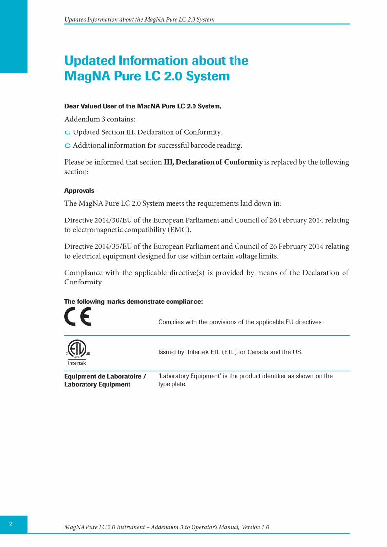
The following marks demonstrate compliance:
Complies with the provisions of the applicable EU directives.
Equipment de Laboratoire / Laboratory Equipment
Issued by Intertek ETL (ETL) for Canada and the US. ‘Laboratory Equipment’ is the product identifier as shown on the type plate.
2 MagNA Pure LC 2.0 Instrument – Addendum 3 to Operator’s Manual, Version 1.0
Updated Information about the MagNA Pure LC 2.0 System
Please read the following update information for the MagNA Pure LC 2.0 System:
Chapter A Overview 2 Specifications of the MagNA Pure LC 2.0 Instrument
2.3 Specifications of the Handheld Bar Code Scanner
As an optional accessory, a hand-held barcode reader for the MagNA Pure 2.0 Instrument needs to be externally supplied.
For reliable barcode reading, specimen barcodes should be printed to achieve ISO/IEC 15416 Grade 2.5 - 4.0 (formerly ANSI X3.182 - 1990 Grade A or B).
Chapter G 2 Troubleshooting
2.1 List of Error Codes
Error Level wrong for Error Code 54.
Error Level should be W instead of F.
(W = Warning, F = Fatal)
MagNA Pure LC 2.0 Instrument – Addendum 3 to Operator’s Manual, Version 1.0 3
If you have any questions regarding the MagNA Pure LC 2.0 System Instrument, please contact your Roche Diagnostics representative.
Published by Roche Diagnostics GmbH Sandhofer Straße 116 68305 Mannheim Germany
© 2016 Roche Diagnostics
0805516500110716
For general laboratory use.
MAG NA PU R E, LIG HTCYCLE R, AN D TAQMAN are trademarks of Roche.
For general laboratory use.
MagNA Pure LC 2.0 Instrument
Addendum 2 to
Operator’s Manual, Version 1.0
Software Version 1.1 August 2012
Information regarding MagNA Pure LC 2.0 Instrument
Dear Valued User of the MagNA Pure LC 2.0 Instrument,
Roche Diagnostics Ltd. has merged into Roche Diagnostics International Ltd and therefore the company name has changed to
Roche Diagnostics International Ltd
In order to harmonize and improve our support, the legal manufacturer changes as follows:
Roche Diagnostics GmbH Sandhofer Strasse 116 68305 Mannheim Germany
If you have any further questions regarding this matter, please do not hesitate to contact your Roche Diagnostics representative. To call, write, fax, or email us, visit the Roche Applied Science home page, http://www.roche-applied-science.com and select your home country. Country-specific contact information will be displayed.
The address of the legal manufacturer in section “Prologue/Contact Addresses” changes as follows:
Old adress New adress
Roche Diagnostics Ltd. Forrenstrasse CH-6343 Rotkreuz Switzerland
Roche Diagnostics GmbH Sandhofer Strasse 116 68305 Mannheim Germany
MAGNA PURE is a trademark of Roche.
For general laboratory use. ©2012 Roche Diagnostics. All rights reserved.
0684
5878
001
a 0
812
Information regarding the MagNA Pure LC 2.0 Instrument Software Update 1.1.24 and the MagNA Pure LC 2.0 Instrument Operator’s Manual Version 1.0
24430909 MagNA Pure LC 2.0-Addendum.indd 124430909 MagNA Pure LC 2.0-Addendum.indd 1 26.01.2010 14:16:1926.01.2010 14:16:19

2
Information regarding the MagNA Pure LC 2.0 Instrument Software Update 1.1.24 and the MagNA Pure LC 2.0 Instrument Operator’s Manual Version 1.0
Please read the following information, which updates information given in the MagNA Pure LC 2.0 Instrument Operator’s Manual Version 1.0.
Dear valued user of the MagNA Pure LC 2.0 Instrument,in March 2010, Roche Applied Science introduced an updated version of the MagNA Pure LC 2.0 Software: Version 1.1.24.
This latest version:
� provides some new features
� fi xes some bugs, found in previous versions
� improves some of the text messages
If you have any further questions regarding this matter, please do not hesitate to contact our Technical Services Department at your best convenience. To call, write, fax, or email us, visit the Roche Applied Science home page, http://www.roche-applied-science.com and select your home country. Country-specifi c contact information will be displayed.
24430909 MagNA Pure LC 2.0-Addendum.indd 224430909 MagNA Pure LC 2.0-Addendum.indd 2 26.01.2010 14:16:2126.01.2010 14:16:21
3
Information regarding the MagNA Pure LC 2.0 Instrument Software Update 1.1.24 and the MagNA Pure LC 2.0 Instrument Operator’s Manual Version 1.0
New Features Provided by the Software Update 1.1.24
Chapter D
2. Sample Ordering
2.2 The Ordering Sub-Tab, page 114
Current Version Changes
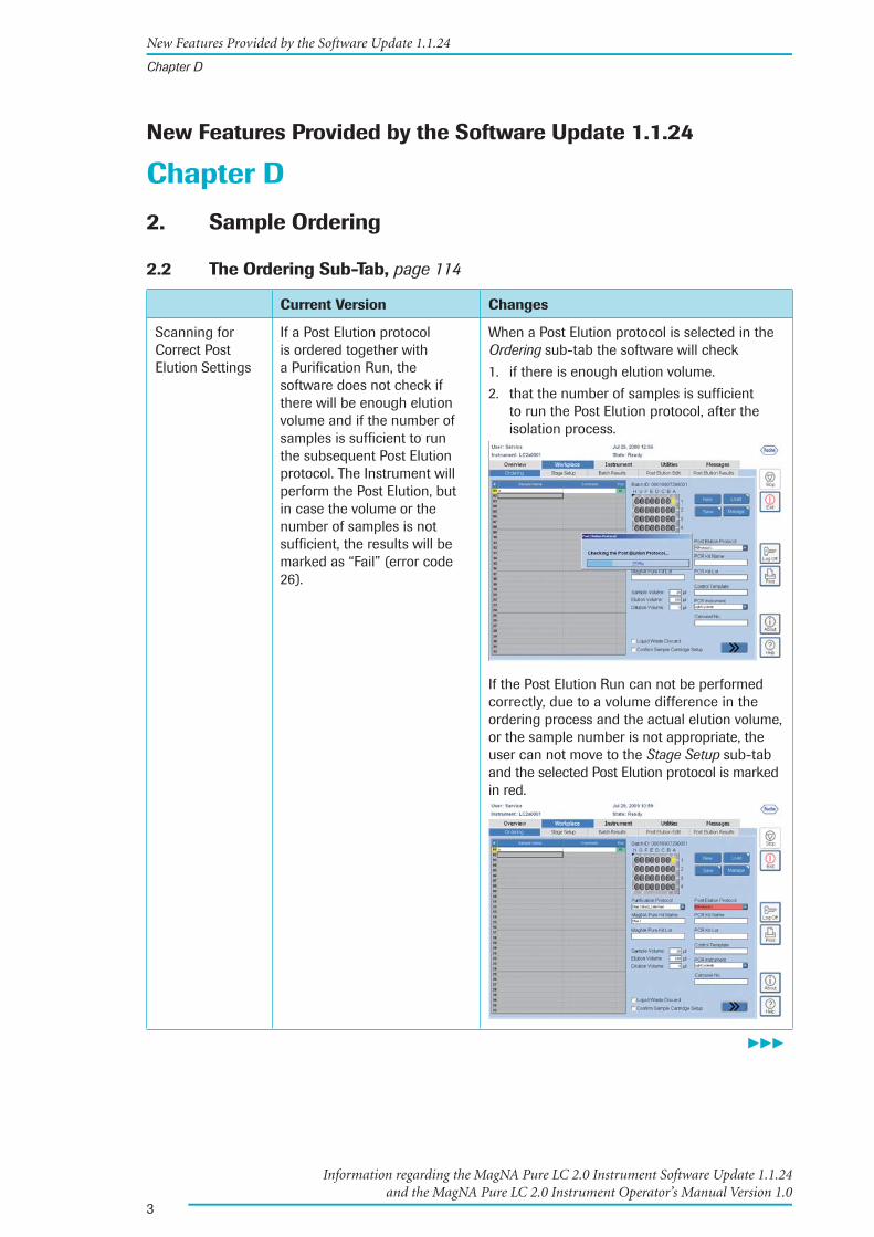
Scanning for Correct Post Elution Settings
If a Post Elution protocol is ordered together with a Purifi cation Run, the software does not check if there will be enough elution volume and if the number of samples is suffi cient to run the subsequent Post Elution protocol. The Instrument will perform the Post Elution, but in case the volume or the number of samples is not suffi cient, the results will be marked as “Fail” (error code 26).
When a Post Elution protocol is selected in the Ordering sub-tab the software will check
1. if there is enough elution volume.
2. that the number of samples is suffi cient to run the Post Elution protocol, after the isolation process.
If the Post Elution Run can not be performed correctly, due to a volume difference in the ordering process and the actual elution volume, or the sample number is not appropriate, the user can not move to the Stage Setup sub-tab and the selected Post Elution protocol is marked in red.
���
New Features Provided by the Software Update 1.1.24
Chapter D
24430909 MagNA Pure LC 2.0-Addendum.indd 324430909 MagNA Pure LC 2.0-Addendum.indd 3 26.01.2010 14:16:2126.01.2010 14:16:21

4
Information regarding the MagNA Pure LC 2.0 Instrument Software Update 1.1.24 and the MagNA Pure LC 2.0 Instrument Operator’s Manual Version 1.0
Current Version Changes
Before accessing the Stage Setup sub-tab a message will be displayed which states that the elution volume is too low or the number or positions of samples is not appropriate.
■
7. Managing User Access
7.1 Access Levels and Privileges, page 132
Current Version Changes
Service Maintenance
Screens
Clicking on the Maintenance Reminder button in the Maintenance Area, provides information about User Maintenance and Service Maintenance. Information about Service Maintenance is only available for users with administrator rights.
All users (Standard Users, as well as Administrators) now have access to information regarding Service Maintenance.
■
New Features Provided by the Software Update 1.1.24
Chapter D
24430909 MagNA Pure LC 2.0-Addendum.indd 424430909 MagNA Pure LC 2.0-Addendum.indd 4 26.01.2010 14:16:2426.01.2010 14:16:24
5
Information regarding the MagNA Pure LC 2.0 Instrument Software Update 1.1.24 and the MagNA Pure LC 2.0 Instrument Operator’s Manual Version 1.0
8. Setting up Parameters, page 136
Current Version Changes
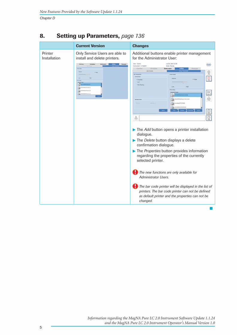
Printer Installation
Only Service Users are able to install and delete printers.
Additional buttons enable printer management for the Administrator User:
� The Add button opens a printer installation dialogue.
� The Delete button displays a delete confi rmation dialogue.
� The Properties button provides information regarding the properties of the currently selected printer.
The new functions are only available for Administrator Users.
The bar code printer will be displayed in the list of printers. The bar code printer can not be defi ned as default printer and the properties can not be changed.
■
New Features Provided by the Software Update 1.1.24
Chapter D
24430909 MagNA Pure LC 2.0-Addendum.indd 524430909 MagNA Pure LC 2.0-Addendum.indd 5 26.01.2010 14:16:2426.01.2010 14:16:24
6
Information regarding the MagNA Pure LC 2.0 Instrument Software Update 1.1.24 and the MagNA Pure LC 2.0 Instrument Operator’s Manual Version 1.0
9. Handling Errors and Messages
9.2 Confi rming Messages, page 139
Current Version Changes
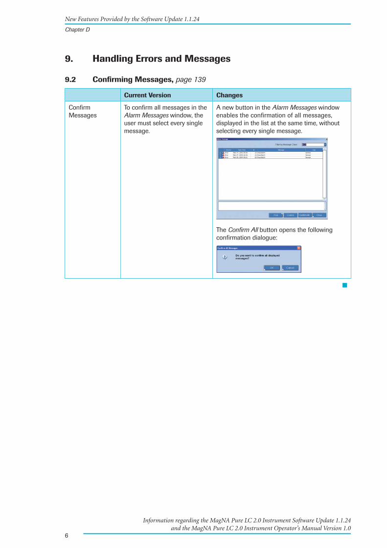
Confi rm Messages
To confi rm all messages in the Alarm Messages window, the user must select every single message.
A new button in the Alarm Messages window enables the confi rmation of all messages, displayed in the list at the same time, without selecting every single message.
The Confi rm All button opens the following confi rmation dialogue:
■
New Features Provided by the Software Update 1.1.24
Chapter D
24430909 MagNA Pure LC 2.0-Addendum.indd 624430909 MagNA Pure LC 2.0-Addendum.indd 6 26.01.2010 14:16:2526.01.2010 14:16:25

7
Information regarding the MagNA Pure LC 2.0 Instrument Software Update 1.1.24 and the MagNA Pure LC 2.0 Instrument Operator’s Manual Version 1.0
Chapter E
2. Programming Post Elution
2.3 The Post Elution Edit (Sub-) Tab, page 151
Current Version Changes
Deletion of Post Elution Protocols
Standard Users are not able to delete an existing Post Elution protocol (.pep fi le) or Sample Ordering Defi nition fi le (.sod fi le). Only Service Users can delete these fi les.
The new Manage button enables the deletion of Post Elution protocols and Sample Ordering Defi nition fi les by Standard Users.
The Manage button opens up a window, where the user must confi rm the decision to delete the fi le.
■
New Features Provided by the Software Update 1.1.24
Chapter E
24430909 MagNA Pure LC 2.0-Addendum.indd 724430909 MagNA Pure LC 2.0-Addendum.indd 7 26.01.2010 14:16:2526.01.2010 14:16:25
8
Information regarding the MagNA Pure LC 2.0 Instrument Software Update 1.1.24 and the MagNA Pure LC 2.0 Instrument Operator’s Manual Version 1.0
Improvements Provided by the Software Update 1.1.24
Chapter C
3. Setting Up the MagNA Pure LC 2.0 Reagent/Sample Stage
3.4 Placing the MagNA Pure LC Reaction Tips (Stage Position 3/4), page 81
Current Version Changes
Indication of Results
If the MagNA Pure LC 2.0 Instrument runs out of tips, or if there is an error picking up tips, but the Operator adds tips, or solves the problem, the process will continue and the eluates will be marked as ‘Pass’.
However, if the Instrument is stopped, waiting for tips or the problem to be solved for an indefi nite period of time, because of evaporation or extended incubation time, it can not be guaranteed that the Purifi cation or Post Elution process was not affected.
If the MagNA Pure LC 2.0 Instrument needs to pause a run (e.g. operator needs to provide more tips or the run was paused by the operator) the eluates will be marked as “Fail”.
■
Improvements Provided by the Software Update 1.1.24
Chapter C
24430909 MagNA Pure LC 2.0-Addendum.indd 824430909 MagNA Pure LC 2.0-Addendum.indd 8 26.01.2010 14:16:2726.01.2010 14:16:27
9
Information regarding the MagNA Pure LC 2.0 Instrument Software Update 1.1.24 and the MagNA Pure LC 2.0 Instrument Operator’s Manual Version 1.0
Chapter G
2. Troubleshooting
2.1 List of Error Codes, page 230
Current Version Changes
Temperature Control
If a Purifi cation Run has been started and the appropriate temperature has not been reached in the preliminary lead time, the software goes back to the ordering screen and no error is reported.
If a Purifi cation Run has been started and the appropriate temperature has not been reached in the preliminary lead time, the software goes back to the ordering screen and the following message is displayed in the alarm area:
Short Message: “Required temperature could not be reached.”
Error Code 62 (Error Level W):
Long Message: “The run was not started because required temperature of Heat Unit could not be reached”
Error Code 63 (Error Level W):
Long Message: “The run was not started because required temperature of Cool Unit 1 could not be reached”
Error Code 64 (Error Level W):
Long Message: “The run was not started because required temperature of Cool Unit 2 could not be reached”
Recommendation: Do not start the Purifi cation Run until the appropriate temperature has been reached.
For information regarding the temperature of the Heating Unit and the Cooling Units, please refer to page 46 in the MagNA Pure LC 2.0 Instrument Operator’s Manual.
���
Improvements Provided by the Software Update 1.1.24
Chapter G
24430909 MagNA Pure LC 2.0-Addendum.indd 924430909 MagNA Pure LC 2.0-Addendum.indd 9 26.01.2010 14:16:2726.01.2010 14:16:27
10
Information regarding the MagNA Pure LC 2.0 Instrument Software Update 1.1.24 and the MagNA Pure LC 2.0 Instrument Operator’s Manual Version 1.0
Current Version Changes
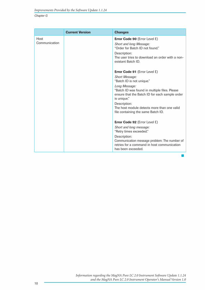
Host Communication
Error Code 90 (Error Level E)
Short and long Message: “Order for Batch ID not found.”
Description: The user tries to download an order with a non-existant Batch ID.
Error Code 91 (Error Level E)
Short Message: “Batch ID is not unique.”
Long Message: “Batch ID was found in multiple fi les. Please ensure that the Batch ID for each sample order is unique.”
Description: The host module detects more than one valid fi le containing the same Batch ID.
Error Code 92 (Error Level E)
Short and long message: “Retry times exceeded.”
Description: Communication message problem: The number of retries for a command in host communication has been exceeded.
■
Improvements Provided by the Software Update 1.1.24
Chapter G
24430909 MagNA Pure LC 2.0-Addendum.indd 1024430909 MagNA Pure LC 2.0-Addendum.indd 10 26.01.2010 14:16:2726.01.2010 14:16:27

11
Information regarding the MagNA Pure LC 2.0 Instrument Software Update 1.1.24 and the MagNA Pure LC 2.0 Instrument Operator’s Manual Version 1.0
Text Corrections of the Current Version of the MagNA Pure LC 2.0 Instrument Operator’s Manual:
Chapter E
5. Editing a Post Elution Protocol
5.1 Editing the Protocol Description Table, page 174/175
Current Version Changes
Deletion of Programming Steps, page 174
To open the pop-up menu, either press the Windows menu key on the keyboard or right-click, using the mouse. Select Delete Row(s).
To open the pop-up menu, either press the Application key (third key to the right of the space bar on the keyboard or right-click, using the mouse. Select Delete Row(s).
Application key:
Copy-Paste Function, page 175
To open the pop-up menu, either press the Windows menu key on the keyboard or right-click, using the mouse. Select Copy.
To open the pop-up menu again, either press the Windows menu key on the keyboard or right-click, using the mouse.
To open the pop-up menu, either press the Application key or right-click, using the mouse. Select Copy.
To open the pop-up menu again, either press the Application key on the keyboard or right-click, using the mouse.
Insert Blank Rows into a Post Elution Protocol, page 175
To open the pop-up menu, either press the Windows menu key on the keyboard or right-click, using the mouse. Select Insert a Blank Row or Insert a Blank Row After. According to the selected function, a blank row is added before or after the selected Aspirate-Dispense Set.
To open the pop-up menu, either press the Application key on the keyboard or right-click, using the mouse. Select Insert a Blank Row or Insert a Blank Row After.
According to the selected function, a blank row is added before or after the selected Aspirate-Dispense Set.
■
Text Corrections of the Current Version of the MagNA Pure LC 2.0 Instrument Operator’s Manual
Chapter E
24430909 MagNA Pure LC 2.0-Addendum.indd 1124430909 MagNA Pure LC 2.0-Addendum.indd 11 26.01.2010 14:16:2726.01.2010 14:16:27
12
Information regarding the MagNA Pure LC 2.0 Instrument Software Update 1.1.24 and the MagNA Pure LC 2.0 Instrument Operator’s Manual Version 1.0
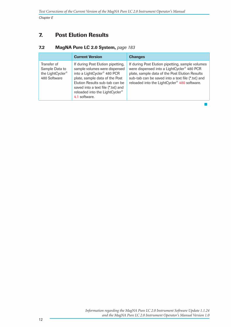
7. Post Elution Results
7.2 MagNA Pure LC 2.0 System, page 183
Current Version Changes
Transfer of Sample Data to the LightCycler® 480 Software
If during Post Elution pipetting, sample volumes were dispensed into a LightCycler® 480 PCR plate, sample data of the Post Elution Results sub-tab can be saved into a text fi le (*.txt) and reloaded into the LightCycler® 4.1 software.
If during Post Elution pipetting, sample volumes were dispensed into a LightCycler® 480 PCR plate, sample data of the Post Elution Results sub-tab can be saved into a text fi le (*.txt) and reloaded into the LightCycler® 480 software.
■
Text Corrections of the Current Version of the MagNA Pure LC 2.0 Instrument Operator’s Manual
Chapter E
24430909 MagNA Pure LC 2.0-Addendum.indd 1224430909 MagNA Pure LC 2.0-Addendum.indd 12 26.01.2010 14:16:2726.01.2010 14:16:27

MagNA Pure LC 2.0 Instrument Operator’s Manual
MPLC_Op-Man-120_RZ.indd 1 21.05.2008 16:38:14 Uhr


3
Table of Contents
Prologue 9
I Revision History ........................................................................................................................9
II Contact Addresses ...................................................................................................................9
III Declaration of Conformity .................................................................................................... 10
IV Warranty ................................................................................................................................... 10
V Trademarks .............................................................................................................................. 10
VI Intended Use of the Instrument .......................................................................................... 11
VII Preamble .................................................................................................................................. 11
VIII How to Use the MagNA Pure LC 2.0 Instrument Operator’s Manual ......................... 12
IX Conventions Used in this Operator’s Manual .................................................................. 13
X Warnings and Precautions ................................................................................................... 16
1 Handling Precautions ....................................................................................................................................... 162 General Precautions ......................................................................................................................................... 173 Electrical Safety .................................................................................................................................................. 18
XI Disposal of the Instrument .................................................................................................. 19
A Overview 23
1 Introduction ....................................................................................................................................................... 23
2 Specifications of the MagNA Pure LC 2.0 Instrument .............................................................. 24
2.1 General Specifications ..................................................................................................................................... 242.2 Sample Capacity................................................................................................................................................. 252.3 Specifications of the Handheld Bar Code Scanner .............................................................................. 252.4 Specifications for LIMS ................................................................................................................................... 252.5 Specifications of the Bar Code Printer ....................................................................................................... 26
B System Description 29
1 The MagNA Pure LC 2.0 System Package ....................................................................................... 29
2 Installation .........................................................................................................................................................31
2.1 Installation Requirements ...............................................................................................................................312.2 Space and Power Requirements .................................................................................................................. 322.3 Environmental Requirements for Operating ............................................................................................ 322.4 Storage Conditions ............................................................................................................................................ 322.5 Unpacking ............................................................................................................................................................ 33
3 Description of the Instrument .................................................................................................................34
3.1 Main Components of the Instrument ......................................................................................................... 353.1.1 Front View of the Instrument ......................................................................................................................... 353.1.2 Back View of the Instrument ......................................................................................................................... 373.1.3 Side Views of the Instrument ........................................................................................................................383.1.4 Nozzle Head and Clot Detection System ..................................................................................................39
3.2 Layout of the MagNA Pure LC 2.0 Reagent/Sample Stage ...............................................................403.3 MagNA Pure LC 2.0 Accessories ................................................................................................................. 473.4 Additional MagNA Pure LC Accessories ..................................................................................................49
4 Disposable Plastics for the MagNA Pure LC 2.0 Instrument .................................................51
4.1 Positions of the Disposable Plastics on the MagNA Pure LC 2.0 Reagent/Sample Stage .... 524.2 Description of Disposable Plastics .............................................................................................................. 534.3 Disposable Plastics Required for Available Purification Protocols ..................................................61
4MagNA Pure LC 2.0 Instrument
Table of Contents
C Operation 65
1 Start-Up ...............................................................................................................................................................66
2 Preparing for a Run ....................................................................................................................................... 67
2.1 Use of the Disposable Lock Bar ................................................................................................................... 672.2 Positioning the MagNA Pure LC Reagent Reservoir Rack ................................................................ 702.3 Positioning the MagNA Pure LC Accessories for Waste ....................................................................712.4 Positioning MagNA Pure LC Cooling Blocks .......................................................................................... 75
3 Setting Up the MagNA Pure LC 2.0 Reagent/Sample Stage ................................................. 77
3.1 Placing the Elution Cartridge and the Storage Cartridge (Stage Position 10/11) ..................... 773.2 Placing the MagNA Pure LC Processing Cartridges(Stage Position 9) ........................................ 783.3 Placing the MagNA Pure LC Tip Stands (Stage Position 8) .............................................................. 793.4 Placing the MagNA Pure LC Reaction Tips (Stage Position 3/4) ....................................................813.5 Filling and Placing the MagNA Pure LC Sample Cartridge (Stage Position 1) .......................... 823.6 Placing the MagNA Pure LC 2.0 Waste Bag ............................................................................................ 833.7 Placing the MagNA Pure LC Waste Bottle ...............................................................................................843.8 Filling and Placing the MagNA Pure LC Reagent Tubs (Stage Position 2) ..................................86
4 Overview of the Purification Workflow ...............................................................................................90
5 Isolation Technology..................................................................................................................................... 92
5.1 Basic Steps of the Working Procedure ...................................................................................................... 925.2 Isolation of DNA, total RNA and viral Total Nucleic Acids (DNA and RNA) ..............................945.3 MagNA Pure LC Nucleic Acid Isolation Kits ...........................................................................................94
6 Shut Down the Instrument ........................................................................................................................ 95
D MagNA Pure LC 2.0 Software 99
1 Overview of the MagNA Pure LC 2.0 Software ..............................................................................99
1.1 Starting the MagNA Pure LC 2.0 Software ..............................................................................................991.2 General MagNA Pure LC 2.0 Software User Interface Conventions ............................................1001.3 The MagNA Pure LC 2.0 Software Main Window ...............................................................................101
1.3.1 The Status Bar ...................................................................................................................................................1011.3.2 The Working Area Tabs ..................................................................................................................................1021.3.3 The Global Action Bar ....................................................................................................................................1021.3.4 The Messages Area ........................................................................................................................................1031.3.5 The Printing Functions ...................................................................................................................................103
1.4 The Overview Tab .............................................................................................................................................106
2 Sample Ordering ...........................................................................................................................................109
2.1 The Purification Protocol ...............................................................................................................................1092.2 The Ordering Sub-Tab ....................................................................................................................................1092.3 Specifying Sample Data ................................................................................................................................1162.4 Performing Sample Ordering ......................................................................................................................118
3 Stage Setup for a Purification Run .....................................................................................................119
3.1 The Stage Setup Sub-Tab ..............................................................................................................................1193.2 Setting up the MagNA Pure LC 2.0 Reagent/Sample Stage ...........................................................122
4 Starting and Stopping a Purification Run .......................................................................................125
5 Monitoring a Purification Run ...............................................................................................................126
6 Batch Results .................................................................................................................................................129
7 Managing User Access .............................................................................................................................132
7.1 Access Levels and Privileges .......................................................................................................................1327.2 The User Access Sub-Tab .............................................................................................................................1337.3 Operations Performed on the User Access Sub-Tab ..........................................................................135
5
Table of Contents
8 Setting up Parameters ...............................................................................................................................136
9 Handling Errors and Messages ............................................................................................................138
9.1 Displaying Messages .....................................................................................................................................1389.2 Confirming Messages ....................................................................................................................................139
10 Data Transfer to and from the MagNA Pure LC 2.0 Instrument .........................................140
10.1 Using LIMS for Data Transfer .....................................................................................................................14010.2 Installing Purification Protocols and Kits ................................................................................................140
E Post Elution 145
1 Introduction .....................................................................................................................................................145
2 Programming Post Elution .......................................................................................................................146
2.1 Post Elution Protocol Editor ..........................................................................................................................1462.2 MagNA Pure LC 2.0 System ........................................................................................................................1462.3 The Post Elution Edit (Sub-)Tab ..................................................................................................................147
3 Programming a New Post Elution Protocol ...................................................................................152
3.1 Selecting MagNA Pure LC Cooling Blocks ............................................................................................1523.2 Defining Type, Name and Initial Volume of Cooling Block Positions ...........................................1553.3 Programming Post Elution Pipetting Steps ............................................................................................161
4 Saving and Loading a Post Elution Protocol .................................................................................172
5 Editing a Post Elution Protocol .............................................................................................................173
5.1 Editing the Protocol Description Table.....................................................................................................1735.2 Editing Reaction Vessel Parameters .........................................................................................................176
6 Starting and Stopping a Post Elution Run or a Post Elution Simulation .......................177
7 Post Elution Results ....................................................................................................................................179
7.1 Post Elution Protocol Editor ..........................................................................................................................1817.2 MagNA Pure LC 2.0 System ........................................................................................................................182
8 Installing the Post Elution Protocol Editor on an External PC .............................................184
8.1 System Requirements ....................................................................................................................................1848.2 Installation ..........................................................................................................................................................184
F Maintenance 189
1 User Maintenance .......................................................................................................................................189
1.1 Automated and Manual Greasing of the O-Rings ..............................................................................1901.1.1 Automated Greasing.......................................................................................................................................1901.1.2 Manual Greasing .............................................................................................................................................193
1.2 Changing the O-Rings ...................................................................................................................................1941.3 Leakage Test ......................................................................................................................................................2001.4 Decontamination..............................................................................................................................................202
1.4.1 General Workflow for Decontaminating the MagNA Pure LC 2.0 Instrument .........................2021.4.2 Decontaminating the Instrument ...............................................................................................................2031.4.3 Decontaminating the Nozzle Head ...........................................................................................................2041.4.4 D econtaminating the Inner Parts of the MagNA Pure LC 2.0 Instrument .................................204
1.5 Tip Discard .........................................................................................................................................................2061.6 Changing the Liquid Drop Catcher ...........................................................................................................2061.7 Liquid Waste Discard .....................................................................................................................................2091.8 Home ....................................................................................................................................................................2101.9 Lock Door / Unlock Door ..............................................................................................................................2111.10 Maintenance Reminder .................................................................................................................................2111.11 Create Problem Report ..................................................................................................................................212
2 Service Maintenance .................................................................................................................................213
6MagNA Pure LC 2.0 Instrument
G Appendix 217
1 Installed Purification Protocols ............................................................................................................217
2 Troubleshooting.............................................................................................................................................219
2.1 List of Error Codes ...........................................................................................................................................2192.2 Troubleshooting Guide ...................................................................................................................................231
3 Ordering Information ..................................................................................................................................237
4 Index .......................................................................................................................................239
Prologue

8MagNA Pure LC 2.0 Instrument

9Prologue
Revision History
Prologue
Revision HistoryI
Version Revision Date
1.0 June 2008
© Copyright 2008, Roche Diagnostics GmbH. All rights reserved.
Information in this document is subject to change without notice. No part of this document may be reproduced or transmitted in any form or by any means, electronic or mechanical, for any purpose, without the express written permission of Roche Diagnostics GmbH.
Questions or comments regarding the contents of this Operator’s Manual can be directed to the address below or to your Roche representative.
Roche Diagnostics GmbH Roche Applied Science Customer Support Nonnenwald 2 82372 Penzberg, Germany
Every effort has been made to ensure that all the information contained in the MagNA Pure LC 2.0 Instrument Operator’s Manual is correct at the time of printing.
However, Roche Diagnostics GmbH reserves the right to make any changes necessary without notice, as part of ongoing product development.
Contact AddressesII
Manufacturer Roche Diagnostics Ltd. Forrenstrasse CH-6343 Rotkreuz Switzerland
Distribution Roche Diagnostics GmbH Sandhofer Straße 116 D-68305 Mannheim Germany
Distribution in USA Roche Diagnostics 9115 Hague Road PO Box 50457 Indianapolis, IN 46250 USA
10MagNA Pure LC 2.0 Instrument
Declaration of Conformity
Declaration of ConformityIII
The Instrument meets the requirements laid down in Council Directive 89/336/EEC relating to “Electromagnetic Compatibility” and Council Directive 73/23/EEC relating to “Low Voltage Equipment”.
The following standards were applied: IEC/EN 61326 (EMC) and IEC/EN 61010-1 (Safety).
UL 61010-1 Electrical Equipment for Measurement, Control and Laboratory Use; Part 1: General Requirements
CAN/CSA-C22.2 No. 61010-1 (Second Edition) Safety Requirements for Electrical Equipment for Measurement, Control and Laboratory Use;
Part 1: General Requirements
WarrantyIV Information on warranty conditions are specified in the sales contract. Contact your Roche representative for further information.
Any unauthorized modification of the MagNA Pure LC 2.0 Instrument and/or of the MagNA Pure LC 2.0 Software results in the invalidity of the guarantee and service con-tract.
TrademarksV LIGHTCYCLER, LC, MAGNA PURE, COBAS and AMPLICOR are trademarks of Roche.
Other brands or product names are trademarks of their respective holders.

11Prologue
Intended Use of the Instrument
Intended Use of the InstrumentVI The MagNA Pure LC 2.0 Instrument is a robotic instrument for:
Automated isolation of nucleic acids (DNA, total RNA, total viral nucleic acids) from ►different kinds of biological research sample material (whole blood, serum, blood cells, culture cells, tissue, bacteria, fungi, etc.) using the specially designed MagNA Pure LC Kits, for the purpose of life science research only and
Automated filling of different kinds of PCR reaction vessels (LightCycler® Capillaries, ►96-well PCR plates, PCR tube strips) with PCR reaction mixes and template nucleic acid, or other reaction tubes, for the making of dilution series, reaction mixes etc.
The MagNA Pure LC 2.0 Instrument system is intended for general laboratory use only.
It was neither developed nor validated by the manufacturer for any kind of in vitro diag-nostic application.
Any use of the MagNA Pure LC 2.0 Instrument System as a front-end sample preparation system for in vitro diagnostic test systems like COBAS® AmpliCor® Instrument tests, is in the sole responsibility of the user. The validation of the combination of MagNA Pure LC nucleic acid isolation and in vitro diagnostic testing must be done by the user, following the relevant national rules.
PreambleVII Before setting-up operation of the MagNA Pure LC 2.0 Instrument, it is important to read this Operator’s Manual thoroughly and completely. Non-observance of the instructions contained in or performing an operation not stated in this Operator’s Manual, could re-sult in safety hazards.
12MagNA Pure LC 2.0 Instrument
How to Use the MagNA Pure LC 2.0 Instrument Operator’s Manual
How to Use the MagNA Pure LC 2.0 VIII Instrument Operator’s Manual
This Operator’s Manual assists with operating the MagNA Pure LC 2.0 Instrument. It contains the following chapters:
Chapter A Overview describes the system’s specifications of the MagNA Pure LC 2.0 Instrument.
Chapter B System Description contains instructions on the installation of the MagNA Pure LC 2.0 Instrument and a description of the system’s components and consumables.
Chapter C Operation describes the operating procedures for the MagNA Pure LC 2.0 Instrument, including the correct placement of the reagents and disposable plastics on the MagNA Pure LC 2.0 Reagent/Sample Stage. Additionally, this chapter gives a short overview of the basic isolation technology workflow.
Chapter D MagNA Pure LC 2.0 Software contains instructions for programming purifica-tion runs and performing data analysis.
Chapter E Post Elution contains instructions for programming post elution runs on the MagNA Pure LC 2.0 Instrument as well as on an external PC.
Chapter F Maintenance describes the maintenance procedures that are required for the MagNA Pure LC 2.0 Instrument.
Chapter G Appendix contains a guide for troubleshooting, ordering information and an index.

13Prologue
Conventions Used in this Operator’s Manual
Conventions Used in this IX Operator’s Manual
Text Conventions
To impart information that is consistent and memorable, the following text conventions are used in this Operator’s Manual:
Numbered Listing Steps in a procedure that must be performed in the order listed.
Italic type, blue Points to a different section in this Operator’s Manual, which should be consulted.
Italic type Describes how to proceed when operating the MagNA Pure LC 2.0 Software.
Abbreviations
The following abbreviations are used in this Operator’s Manual:
Long Name Abbreviation
MagNA Pure LC 2.0 Reagent/Sample Stage Reagent/Sample Stage
MagNA Pure LC Reagent Reservoir Rack Reagent Reservoir Rack
MagNA Pure LC 2.0 Tip Waste Slide Tip Waste Slide
MagNA Pure LC Liquid Waste Funnel Liquid Waste Funnel
MagNA Pure LC Waste Bottle Tray Waste Bottle Tray
MagNA Pure LC Reaction Tip (small) Small Reaction Tip(s)
MagNA Pure LC Reaction Tip (large) Large Reaction Tip(s)
MagNA Pure LC Reaction Tip Trays Reaction Tip Trays
MagNA Pure LC Tip Stand Tip Stand(s)
MagNA Pure LC Reagent Tub (small) Small Reagent Tub(s)
MagNA Pure LC Reagent Tub (large) Large Reagent Tub(s)
MagNA Pure LC Medium Reagent Tub 20 Medium Reagent Tub(s) M20
MagNA Pure LC Medium Reagent Tub 30 Medium Reagent Tub(s) M30
MagNA Pure LC Tub Lid (small, medium) Small/Medium Tub Lid(s)
MagNA Pure LC Tub Lid (large) Large Tub Lid(s)
MagNA Pure LC Tub Lids Tub Lids
MagNA Pure LC Tub Lid Seal Tub Lid Seal(s)
MagNA Pure LC Processing Cartridge Processing Cartridge(s)
MagNA Pure LC Sample Cartridge Sample Cartridge(s)
MagNA Pure LC Cartridge Seal Cartridge Seal(s)
MagNA Pure LC Waste Bottle Waste Bottle
MagNA Pure LC 2.0 Waste Bags Waste Bags
MagNA Pure LC 2.0 Waste Box Waste Box
MagNA Pure LC 2.0 Waste Box Lid Waste Box Lid
MagNA Pure LC Greasing Set Greasing Set
MagNA Pure LC Cooling Block, LC Centrifuge Adapters
LC Centrifuge Adapters Cooling Block
MagNA Pure LC Cooling Block, 96-well PCR Plate 96-well PCR Plate Cooling Block
MagNA Pure LC Cooling Block, Reaction Tubes Reaction Tubes Cooling Block
14MagNA Pure LC 2.0 Instrument
Conventions Used in this Operator’s Manual
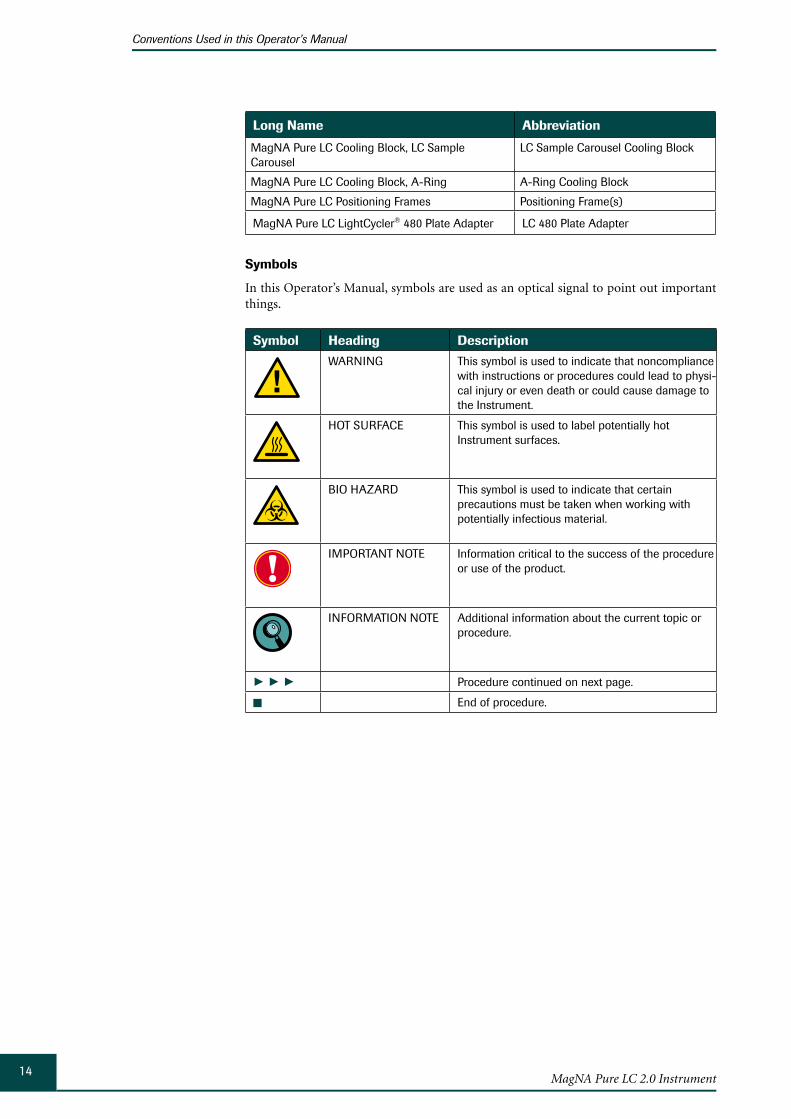
Long Name Abbreviation
MagNA Pure LC Cooling Block, LC Sample Carousel
LC Sample Carousel Cooling Block
MagNA Pure LC Cooling Block, A-Ring A-Ring Cooling Block
MagNA Pure LC Positioning Frames Positioning Frame(s)
MagNA Pure LC LightCycler® 480 Plate Adapter LC 480 Plate Adapter
Symbols
In this Operator’s Manual, symbols are used as an optical signal to point out important things.
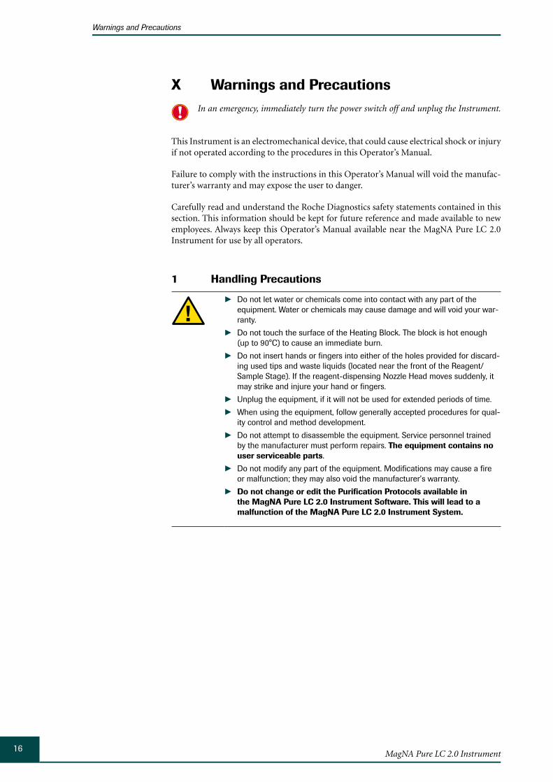
Symbol Heading Description
WARNING This symbol is used to indicate that noncompliance with instructions or procedures could lead to physi-cal injury or even death or could cause damage to the Instrument.
HOT SURFACE This symbol is used to label potentially hot Instrument surfaces.
BIO HAZARD This symbol is used to indicate that certain precautions must be taken when working with potentially infectious material.
IMPORTANT NOTE Information critical to the success of the procedure or use of the product.
INFORMATION NOTE Additional information about the current topic or procedure.
► ► ► Procedure continued on next page.
■ End of procedure.

15Prologue
Conventions Used in this Operator’s Manual
The following symbols appear on the Instrument:
Symbol Heading Description
MANUFACTURER OF DEVICE
On the Instrument type plate.
CE MARK The CE mark on the Instrument type plate expresses conformity with requirements of the directives relevant for this Instrument.
cETLus MARK On the Instrument type plate.
CONSULT THE OPERATOR’S MANUAL
On the door of the Instrument.
HOT SURFACE On the Heating Block.
KEEP HANDS AWAY On the reagent-dispensing Nozzle Head
BIO HAZARD Near the MagNA Pure LC 2.0 Tip Waste Slide.
WEEE Electrical and electronic equipment marked with this symbol are covered by the European directive WEEE.
The symbol denotes that the equipment must not be disposed off in the municipal waste system.
16MagNA Pure LC 2.0 Instrument
Warnings and Precautions
X Warnings and Precautions In an emergency, immediately turn the power switch off and unplug the Instrument.
This Instrument is an electromechanical device, that could cause electrical shock or injury if not operated according to the procedures in this Operator’s Manual.
Failure to comply with the instructions in this Operator’s Manual will void the manufac-turer’s warranty and may expose the user to danger.
Carefully read and understand the Roche Diagnostics safety statements contained in this section. This information should be kept for future reference and made available to new employees. Always keep this Operator’s Manual available near the MagNA Pure LC 2.0 Instrument for use by all operators.
Handling Precautions1
Do not let water or chemicals come into contact with any part of the ►equipment. Water or chemicals may cause damage and will void your war-ranty.
Do not touch the surface of the Heating Block. The block is hot enough ►(up to 90°C) to cause an immediate burn.
Do not insert hands or fingers into either of the holes provided for discard- ►ing used tips and waste liquids (located near the front of the Reagent/Sample Stage). If the reagent-dispensing Nozzle Head moves suddenly, it may strike and injure your hand or fingers.
Unplug the equipment, if it will not be used for extended periods of time. ►When using the equipment, follow generally accepted procedures for qual- ►ity control and method development.
Do not attempt to disassemble the equipment. Service personnel trained ►by the manufacturer must perform repairs. The equipment contains no user serviceable parts.
Do not modify any part of the equipment. Modifications may cause a fire ►or malfunction; they may also void the manufacturer’s warranty.
Do not change or edit the Purification Protocols available in ►the MagNA Pure LC 2.0 Instrument Software. This will lead to a malfunction of the MagNA Pure LC 2.0 Instrument System.
17Prologue
Warnings and Precautions
General Precautions2 The MagNA Pure LC 2.0 Instrument was designed to ensure safe operation. However, since biological research sample material may be processed in the Instrument, there is a possible risk of infection. Therefore, when handling potentially infectious material, always follow standard safety procedures and take the following steps into account, to minimize the chance of contamination or infection:
The Instrument should not be used to analyze infectious materials unless additional safety measures to ensure safe sample handling (e.g., placing the Instrument in a lam-inar flow biological safety cabinet, or using a purification protocol which allows exter-nal sample lysis) are taken beforehand.
Always wear a laboratory coat, gloves and a mask, when handling specimens and re- ►agents.
Discard unused reagents and waste (solid and liquid), in accordance with country, ►federal, state and local regulations. Material Safety Data Sheets (MSDS) are available upon request from your local Roche office.
Keep the MagNA Pure LC 2.0 Tip Waste Slide clean. ►
Do not operate the Instrument without a MagNA Pure LC 2.0 Waste Bag secured to ►the end of the Tip Waste Slide, in the MagNA Pure LC 2.0 Waste Box.
Discard the MagNA Pure LC 2.0 Waste Bag and the filled MagNA Pure LC Waste Bottle ►(only necessary when performing the optional Liquid Waste Discard function) after preparing each full set of samples (32 samples).
After sample preparation is complete: ►
Remove and autoclave all disposable plastics, if you worked with infectious sample ►material.
Wipe the MagNA Pure LC 2.0 Reagent/Sample Stage with bleach (0.5% solution of ►sodium hypochlorite) and let it react for 10 min. To remove the bleach completely, wipe the Instrument surface with 70% ethanol, followed by pure water.
After using bleach, ventilate the Instrument for at least 1 hour. Accessories (e.g., Cool-ing Blocks, Reagent Reservoir Rack) may be treated the same way.
Never clean accessories in a dishwasher !
Wipe the front surface of the magnetic plate with 70% ethanol, using a smooth cloth. ►
After cleaning the Reagent/Sample Stage with bleach and water/ethanol, decontami- ►nate the Instrument using the built-in UV lamp, as follows (see section Decontamina-tion for details):
Close the door and select the ► Decontamination button on the Maintenance sub-tab.
Set the decontamination time (recommended setting 8 hours). ►
Select the ► Start button.
Bleach can be used for disinfection and removal of contaminating nucleic acids and nucleases at the same time. For sole disinfection purposes, one may also use commer-cially available disinfection reagents (please contact the respective distributors in your country for details). For removal of contaminating nucleic acids and/or nucleases, decontaminating agents like LTK008 or DNA/RNA ZAP may be used. Be aware that decontamination agents do not disinfect. Please follow the instructions of the respec-tive manufacturer (see section Decontaminating the Instrument for details on decon-tamination agents).
18MagNA Pure LC 2.0 Instrument
Warnings and Precautions
The MagNA Pure LC 2.0 Instrument is not a fully airtight device. There is an air flow under the Instrument platform. Although total air flow from the platform is filtered through the HEPA filter (see section Main Components of the Instrument for details), it cannot be ruled out completely that the platform atmosphere never leaves the Instrument without prior filtration by the HEPA filter.
Therefore, the MagNA Pure LC 2.0 Instrument does not have the same functional-ity as a laminar flow biological safety cabinet and should not be used for analysis of infectious sample material, unless additional safety measures ensure safe sample handling.
Electrical Safety3
The MagNA Pure LC 2.0 Instrument is designed in accordance with Protection Class I (IEC). The chassis/housing of the Instrument is connected to protection earth (PE) by means of a cable. For protection against electrical shock hazards, the Instrument must be directly connected to an approved power source, such as a three-wire grounded receptacle for the 230V line. Where an ungrounded receptacle is encountered, a qualified electrician must replace it with a prop-erly (PE) grounded receptacle, in accordance with the local electrical code. An extension must not be used. Any break in the electrical ground path, whether inside or outside the Instrument, could create a hazardous condition. Under no circumstances should the user attempt to modify or deliberately defeat the safety features of this Instrument. If the power cord becomes cracked, frayed, broken, or otherwise damaged, it must be replaced immediately with the equivalent part from Roche Diagnostics.
19Prologue
Disposal of the Instrument
Disposal of the InstrumentXI
Disposal Recommendations
All electrical and electronic products should be disposed off separately from the municipal waste system. Proper disposal of your old appliance prevents potential negative consequences for the environment and human health.
The Instrument must be treated as biologically contaminated-hazardous waste. Decontamination (i.e., a combination of processes, including cleaning, disinfection and/or sterilization) is required before reuse, recycling or disposal.
Dispose the Instrument according to local and/or labor regulations.
For more information contact your local Roche Support personnel.
Components of your Control Unit such as the computer, monitor, keyboard, etc. which are marked with the crossed-out wheeled bin symbol are covered by the European Directive 2002/96/EC on waste electrical and electronic equipment (WEEE) of the European Parliament and the Council of 27 January 2003.
These items must be disposed of, via designated collection facilities appointed by government or local authorities.
For more information about disposal of your old product, please contact your city office, waste disposal service or your local Roche Support personnel.
Constraint
It is left to the responsible laboratory organization to determine whether control unit components are contaminated or not. If contaminated, treat in the same way as the Instrument.

20MagNA Pure LC 2.0 Instrumen

Chapter A • Overview
22MagNA Pure LC 2.0 Instrument
Table of Contents
AA A Overview
1 Introduction ....................................................................................................................................................... 23
2 Specifications of the MagNA Pure LC 2.0 Instrument .............................................................. 24
2.1 General Specifications ..................................................................................................................................... 242.2 Sample Capacity................................................................................................................................................. 252.3 Specifications of the Handheld Bar Code Scanner .............................................................................. 252.4 Specifications for LIMS ................................................................................................................................... 252.5 Specifications of the Bar Code Printer ....................................................................................................... 26
23Overview
Introduction
AAOverview
Introduction1 Magnetism is the underlying principle of the automated nucleic acid isolation performed by the highly flexible MagNA Pure LC 2.0 Instrument of Roche Applied Science. The MagNA Pure LC 2.0 Instrument permits automated nucleic acid purification that matches the high standards for speed, accuracy and reliability in PCR of the LightCycler® Sys-tem. Furthermore, the MagNA Pure LC 2.0 Instrument is able to fill automatically, Light Cycler® Capillaries, as well as other types of PCR reaction vessels, with purified nucleic acids and (RT-)PCR master mixes. This demonstrates the extraordinary flexibility of the MagNA Pure LC 2.0 System and its associated MagNA Pure LC Kits.

24MagNA Pure LC 2.0 Instrument
Specifications of the MagNA Pure LC 2.0 Instrument
General Specifications
AA 2 Specifications of the MagNA Pure LC 2.0 Instrument
General Specifications2.1
Instrument type Bench top standalone instrument
Width Instrument housing
Including touch-screen
108 cm
137 cm
Depth Back side to front door
Including front door handle
Including Waste Box
71 cm
77 cm
81 cm
Height With front door closed
With front door completely opened
Maximum height during opening/closing
91 cm
109 cm
114 cm
Weight Approx. 178 kg, including transportation bars
Approx. 170 kg, without transportation bars
Power supply 100 to 125 V (-15 %, +10 %);
200 to 240 V (-15 %, +10 %)
Frequency 50/60 Hz
Power consumption 800 VA max.
Fuses 10 AT/250 V for 100 to 125 V
5 AT/250 V for 200 to 240 V
Heat emission 1,440 kJ/h (max.)
860 kJ/h (average value during operation)
Protection Class I
Installation category Class II
Electromagnetic emission Class B
Electromagnetic radiation disturbances
Class B
User interface User-friendly interface, based on Windows XP operating system

25Overview
Specifications of the MagNA Pure LC 2.0 Instrument
Sample Capacity
AASample Capacity2.2
Sample capacity Up to 32 samples per batch*)
Liquid dispensing capacity 5 to 1,000 µl
Dispensing accuracy 5 to 100 µl: < 3% CV
100 to 1,000 µl: < 2% CV
Elution volume accuracy > 90% (mean value; CV 5%) of the elution volume defined in the purification protocol
Processing time Approx. 60 to 180 min, depending on the protocol type and sample number
Sample volume 20 to 1,000 µl
Elution volume 50 to 200 µl
Dilution volume 100 to 900 µl
*)With the 8-nozzle multi pipet, up to 32 (4 x 8) samples can be processed in one run.
2.3 Specifications of the Handheld Bar Code ScannerA handheld bar code scanner for the MagNA Pure 2.0 Instrument can be purchased as an optional accessory. Please contact your local Roche representative for details.
The handheld bar code scanner is connected to the Instrument via one of the USB ports.
Use the handheld bar code scanner to scan information from bar codes into text input fields of the MagNA Pure LC 2.0 Software.
Interface
USB port
Supported bar code types
Code 39 (250 — 500 µm; Code with Check digit, min. code length = 2) ►Code 2 of 5 (250 — 500 µm; Code with Check digit, min. code length = 2) ►Code 128 (250 — 500 µm; min. code length = 2) ►
2.4 Specifications for LIMSThe MagNA Pure LC 2.0 Software offers the possibility to use a Laboratory Information Management System (LIMS) for data transfer. Data can be transferred via an HL7 transfer protocol, if the MagNA Pure LC 2.0 Instrument is connected to the LIMS over a LAN connection.
This allows results to be uploaded, automatically or manually to the LIMS. As well, the download of the Sample Order Table for the purification run is possible from the LIMS.
File Sharing is also possible, however, we recommend for security reasons to not use this, unless the Instrument is part of a completely separate or isolated network.
For further information regarding setting up the MagNA Pure LC 2.0 Instrument with a LIMS, please contact your local Roche representative.

26MagNA Pure LC 2.0 Instrument
Specifications of the MagNA Pure LC 2.0 Instrument
Specifications of the Bar Code Printer
AA2.5 Specifications of the Bar Code PrinterA bar code printer for the MagNA Pure 2.0 Instrument can be purchased as an optional accessory. Please contact your local Roche representative for details.
The MagNA Pure LC 2.0 Software offers the possibility to connect a bar code printer for printing of bar code labels. Labels can be used to label the Sample/Storage Cartridge, pri-mary sample tubes, the LightCycler® Sample Carousel, or COBAS® AmpliCor® A-Rings. You can find the respective functions needed for printing by selecting the Print button on the Global Action Bar. For more information, see section The Printing Functions.
The desktop printers LP/TLP 2844 manufactured by Zebra Technologies Corp., Vernon Hills, IL, USA, have been tested and verified for use with the MagNA Pure LC 2.0 Instru-ment.

Chapter B • System Description
28MagNA Pure LC 2.0 Instrument
Table of Contents
BB
B System Description
1 The MagNA Pure LC 2.0 System Package ....................................................................................... 29
2 Installation .........................................................................................................................................................31
2.1 Installation Requirements ...............................................................................................................................312.2 Space and Power Requirements .................................................................................................................. 322.3 Environmental Requirements for Operating ............................................................................................ 322.4 Storage Conditions ............................................................................................................................................ 322.5 Unpacking ............................................................................................................................................................ 33
3 Description of the Instrument .................................................................................................................34
3.1 Main Components of the Instrument ......................................................................................................... 353.1.1 Front View of the Instrument ......................................................................................................................... 353.1.2 Back View of the Instrument ......................................................................................................................... 373.1.3 Side Views of the Instrument ........................................................................................................................383.1.4 Nozzle Head and Clot Detection System ..................................................................................................39
3.2 Layout of the MagNA Pure LC 2.0 Reagent/Sample Stage ...............................................................403.3 MagNA Pure LC 2.0 Accessories ................................................................................................................. 473.4 Additional MagNA Pure LC Accessories ..................................................................................................49
4 Disposable Plastics for the MagNA Pure LC 2.0 Instrument .................................................51
4.1 Positions of the Disposable Plastics on the MagNA Pure LC 2.0 Reagent/Sample Stage .... 524.2 Description of Disposable Plastics .............................................................................................................. 534.3 Disposable Plastics Required for Available Purification Protocols ..................................................61
29System Description
The MagNA Pure LC 2.0 System Package
BB
System Description
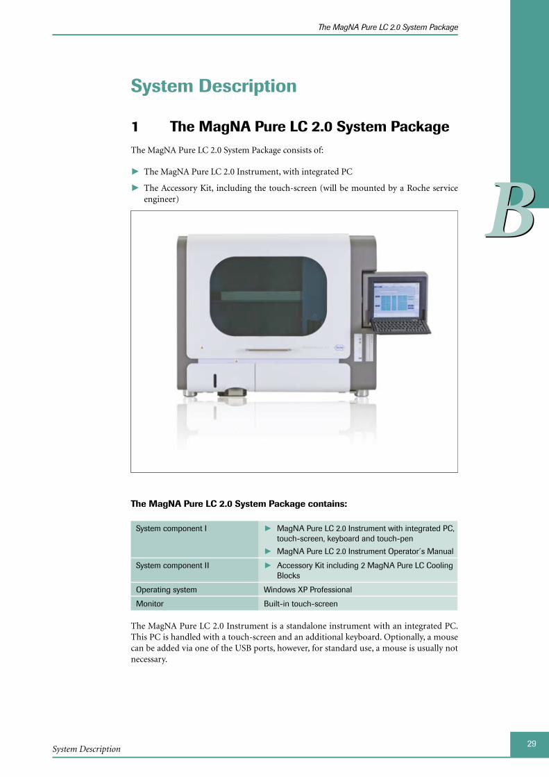
The MagNA Pure LC 2.0 System Package1 The MagNA Pure LC 2.0 System Package consists of:
The MagNA Pure LC 2.0 Instrument, with integrated PC ►
The Accessory Kit, including the touch-screen (will be mounted by a Roche service ►engineer)
The MagNA Pure LC 2.0 System Package contains:
System component I MagNA Pure LC 2.0 Instrument with integrated PC, ►touch-screen, keyboard and touch-pen
MagNA Pure LC 2.0 Instrument Operator´s Manual ►
System component II Accessory Kit including 2 MagNA Pure LC Cooling ►Blocks
Operating system Windows XP Professional
Monitor Built-in touch-screen
The MagNA Pure LC 2.0 Instrument is a standalone instrument with an integrated PC. This PC is handled with a touch-screen and an additional keyboard. Optionally, a mouse can be added via one of the USB ports, however, for standard use, a mouse is usually not necessary.
30MagNA Pure LC 2.0 Instrument
The MagNA Pure LC 2.0 System Package
BB
An independent external PC can be used to set up Post Elution protocols. Specifications for this computer are as follows:
External computer Processor speed: 800 Mhz min. ►512 MB RAM min. ►20 GB HDD min. ►CD-ROM Drive ►
Operating system Windows XP, Windows Vista
The Accessory Kit contains all necessary accessories for the MagNA Pure LC 2.0 Instrument, including:
Quantity Item2 MagNA Pure LC Reagent Reservoir Rack
(Cat. No. 03 253 767 001)
2 MagNA Pure LC Cooling Blocks*, including:
MagNA Pure LC Cooling Block, LC Centrifuge Adapters ►(Cat. No. 12 190 664 001, 1 cooling block with 32 LightCycler® Centrifuge Adapters)
MagNA Pure LC Cooling Block, 96-well PCR Plate ►(Cat. No. 12 189 674 001, 1 cooling block)
1 MagNA Pure LC LightCycler® 480 Plate Adapter
(Cat. No. 05 323 983 001)
1 MagNA Pure LC 2.0 Tip Waste Slide
(Cat. No. 05 324 122 001)
1 MagNA Pure LC Waste Bottle Tray
(Cat. No. 03 253 813 001)
1 MagNA Pure LC Liquid Waste Funnel
(Cat. No. 03 253 805 001)
1 MagNA Pure LC 2.0 Waste Box (Cat. No. 05 323 991 001)
1 MagNA Pure LC 2.0 Waste Box Lid
(Cat. No. 05 324 114 001)
One of each Power cable (for U.S. outlets)
Power cable (for European outlets)
1 MagNA Pure LC Greasing Set
(Cat. No. 03 561 402 001)
1 O-Ring Exchange Tool
1 Touch-pen with holder
1 MagNA Pure LC 2.0 Instrument Operator’s Manual and a CD with the MagNA Pure LC 2.0 Instrument Operator’s Manual and Post Elution Software
*The two MagNA Pure LC Cooling Blocks with the Instrument may also be ordered sepa-rately. Three additional cooling blocks are available:
MagNA Pure LC Cooling Block, LC Sample Carousel ►
MagNA Pure LC Cooling Block, Reaction Tubes ►
MagNA Pure LC Cooling Block, A-Ring ►
For details, please refer to section Additional MagNA Pure LC Cooling Blocks.
31System Description
Installation
Installation Requirements
BB
Installation2 Installation of the MagNA Pure LC 2.0 Instrument is performed by a Roche Diagnostics representative only. Furthermore, the integrated touch-screen computer comes with pre-installed software. You are responsible for providing the necessary facilities as detailed below.
In the event that the MagNA Pure LC 2.0 Instrument must be moved to a different loca-tion, it is strongly recommend to contact your local Roche representative to organize the move because
Of the weight of the Instrument and ►
It is necessary to perform an adjustment procedure, called Easy Teaching after the In- ►strument has been moved. This is only performed by your local Roche representative.
In order to guarantee the correct function of the Instrument, it is essential to perform the Easy Teaching procedure. If the adjustment is not performed, or performed incor-rectly, either the Instrument could be damaged or the Instrument performance could be affected (e.g., pipetting accuracy, yield of nucleic acids).
To ensure that the MagNA Pure LC 2.0 Instrument operates correctly, the installation site for the Instrument should meet the prerequisites and conditions described in the following sections:
2.1 Installation Requirements
Location The MagNA Pure LC 2.0 Instrument is intended for indoor use only.
Place the Instrument on a flat, stable and vibration free surface. ►Do not place the Instrument next to any Instrument or equipment ►that is likely to produce electrical noise and/or voltage fluctuations, that will interfere with Instrument operation.
Do not place the Instrument in direct sunlight or under a bright ceil- ►ing lamp. Light intensity inside the laboratory should not be higher than 2.5 kLux. If a window has screens or blinds, ensure that no strips of light can fall on to the region of the Reagent/Sample Stage, because this could activate the Clot Detection sensor.
If you want to use the LIMS connectivity, you need a LAN connec- ►tion.
Noise level The noise level of the Instrument, with a frequency range from 20 Hz to 20 kHz, is below 65 dB. With a frequency range from 20 kHz to 100 kHz, it is below 110 dB.
Ensure that there is space around and behind the Instrument to perform, for e.g., ser-vice on the Instrument.
The MagNA Pure LC 2.0 Instrument generates up to 700 Watt which are converted into heat. It is possible to cool the MagNA Pure LC 2.0 Instrument with an appropri-ate cooling device. Adequate arrangements should be made for the free flow of air for effective cooling.
32MagNA Pure LC 2.0 Instrument
Installation
Space and Power Requirements
BB
2.2 Space and Power RequirementsPlace the MagNA Pure LC 2.0 Instrument on a site that can support the following instru-ment requirements:
Dimensions The MagNA Pure LC 2.0 Instrument is 108 cm wide, 77 cm deep and 91 cm high with the door closed. With the door open, it has a maximum height of 114 cm.
The Instrument size does not include the Waste Box.
Weight The MagNA Pure LC 2.0 Instrument has a weight of approximately 170 kg, without transportation bars (178 kg, including transportation bars).
Power The MagNA Pure LC 2.0 Instrument needs an independent grounded electrical power outlet, which can supply 100 to 125 V or 200 to 240 V AC, at 10 A and 50/60 Hz.
Because power can be interrupted, we recommend the use of an Uninterruptible Power Supply (UPS).
Do not plug any other electrical device into the outlet used for the MagNA Pure LC 2.0 Instrument. Ensure the Instrument´s power-plug is always earthed.
Environmental 2.3 Requirements for OperatingThe MagNA Pure LC 2.0 Instrument has been designed to safely operate at the following conditions:
Room temperature 15°C to 32°C
Relative humidity 30% to 80% (no condensation) for temperatures up to 32°C
Cooling Unit 1 and Cooling Unit 2 are excepted.
Altitude Between 0 and 2,000 meters, above sea level
Transient category II (according to Installation categories)
Pollution degree 2
2.4 Storage ConditionsThe MagNA Pure LC 2.0 Instrument has to be transported and stored at the following conditions.
Temperature -25°C to +60°C
Relative humidity 10% to 100% (limited to the absolute humidity of 0.1g/m3 to 35g/m3)
Air pressure 106 kPa to 70 kPa
33System Description
Installation
Unpacking
BB
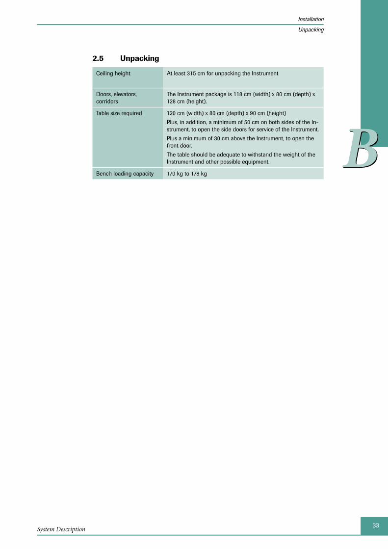
2.5 Unpacking
Ceiling height At least 315 cm for unpacking the Instrument
Doors, elevators, corridors
The Instrument package is 118 cm (width) x 80 cm (depth) x 128 cm (height).
Table size required 120 cm (width) x 80 cm (depth) x 90 cm (height)
Plus, in addition, a minimum of 50 cm on both sides of the In-strument, to open the side doors for service of the Instrument.
Plus a minimum of 30 cm above the Instrument, to open the front door.
The table should be adequate to withstand the weight of the Instrument and other possible equipment.
Bench loading capacity 170 kg to 178 kg

34MagNA Pure LC 2.0 Instrument
Description of the Instrument
BB
Description of the Instrument3 The MagNA Pure LC 2.0 Instrument is a robotic Instrument for automated nucleic acid isolation from biological research sample material, as well as filling of PCR reaction vessels (LightCycler® Capillaries, 96-well PCR plates, PCR tubes) and reaction tubes (1.5 ml).
It consists of a benchtop instrument with an integrated touch-screen computer. The cen-tral processing unit of the Instrument is the Robotic Arm with its 8-Nozzle Pipette Head. With this Pipette Head, variable sample numbers from 1 to 32 can be processed in one run. In addition, this Pipette Head has a specialized sensor unit, which is responsible for detection of clots in sample material and loss of reaction tips.
Here is a brief overview of the workflow of a typical processing run with the MagNA Pure LC 2.0 Instrument:
Sample Ordering:
After starting the MagNA Pure LC 2.0 Software, the appropriate purification protocol must be selected by the user, according to the starting sample material and the type of nucleic acid to be isolated.
The user enters additionally needed protocol parameters and sample data on the Ordering sub-tab.
Start Information:
Type and amount of isolation reagents and disposable plastics required for the puri-fication run are automatically calculated by the software, according to input param-eters. This information is displayed on the Stage Setup sub-tab.
Placement of Reagents and Disposable Plastics:
Isolation reagents are pipetted into nuclease-free, disposable Reagent Tubs. Reagent Tubs and other disposable plastics, such as Processing Cartridges and Reaction Tips, are placed on the Reagent/Sample Stage. Samples are loaded into the Sample Cartridge.
Batch Run:
The Instrument automatically performs all remaining steps of the procedure using specially designed nuclease-free, disposable Reaction Tips.
These Reaction Tips not only transfer the samples, but also serve as reaction vials for the procedure. Within the tips, nucleic acids are bound to magnetic beads, washed free of impurities and finally eluted from the magnetic beads.
Eluted nucleic acids are then transferred into the wells of the Storage Cartridge. They can be directly dispensed into PCR reaction vials, such as LightCycler® Capillaries, by using the Post Elution function, or stored for further use.
During the run, used Reaction Tips are automatically discarded into the Waste Box. Liquid waste may also be collected in a disposable container at the end of the run.
Post Elution:
After completion of a nucleic acid purification run, the MagNA Pure LC 2.0 Instrument can be instructed to transfer the eluted nucleic acid samples into LightCycler® Capil-laries, wells of a PCR plate, or reaction tubes. Also, the set-up of PCR master mixes or dilution series can be performed automatically by the Instrument.
■
For detailed information on the Isolation Technology, refer to section Isolation Technol-ogy.

35System Description
Description of the Instrument
Main Components of the Instrument
BB
3.1 Main Components of the Instrument
3.1.1 Front View of the Instrument
2
4
3
1
12
10
11876
9
5
Number Instrument Part Description
1 Housing Builds up the main body part of the Instrument. Consists of painted sheet metal and protects from electromagnetic influences, chemicals and UV light.
2 Front Door The Front Door is impervious to UV light from inside the Instrument, in case the decontamination func-tion is activated, but permits good view to the inside of the Instrument. Locking of the door is controlled by the software. Movement of the Robotic Arm is only possible after the Instrument Door is closed and locked.
3 Robotic Arm The Robotic Arm moves over the Reagent/Sample Stage in three directions: x-, y- and z-direction. The Robotic Arm transports the Reaction Tips to the re-quired positions of pipetting or tip pick up/discard.
4 UV Lamp (behind the Front Door)
The UV Lamp (emission 254 nm) permits decontami-nation of the Reagent/Sample Stage from nucleic acids.
5 Touch-Screen and Keyboard
The Touch-Screen and Keyboard serve as the user interface to operate the Instrument.
6 Power On Button and Status Indicator LEDs
The Instrument is switched on with the ‘Power On’ button. The two LEDs indicate the current status of the Instrument (see section MagNA Pure LC 2.0 Instrument Status Indication by Front Side LEDs for details)
7 Buttons for Setting Screen Contrast
By using the + and - buttons, the brightness of the touch-screen is set.

36MagNA Pure LC 2.0 Instrument
Description of the Instrument
Main Components of the Instrument
BB
Number Instrument Part Description
8 USB and Optical Drive
Via USB or optical drive, the operator can transfer the generated data easily to other instruments or computers for
Positive sample tracking ►Documentation ►Troubleshooting ►Loading new MagNA Pure LC 2.0 purification ►protocols, when available from Roche.
9 Nozzle Head and Magnetic Plate
The Nozzle Head performs all pipetting steps. Its 8 Nozzles can hold up to eight Reaction Tips. The Nozzle pitch is suitable for pipetting into the wells of a standard 96-well PCR Plate. In addition, the Nozzle Head contains the Tip-Loss and Clot-Detection System.
The Magnetic Plate contains a permanent magnet and is movable forward and backward.
The distance between the magnet and the Reaction Tips is controlled by the software.
For cleaning of the Magnetic Plate, wipe its surface with 70% ethanol, using a smooth cloth.
10 Reagent/Sample Stage
The Reagent/Sample Stage provides the positions for placement of the Sample Cartridge, Reagent Tubs placed in the Reagent Reservoir Rack, Reaction Tip Trays, Processing Cartridges and Tip Stands. It also has a Heating Unit for placement of the Elution Cartridge and two Cooling Units for placement of the Storage Cartridge and MagNA Pure LC Cooling Blocks, used during Post Elution. See section Layout of the MagNA Pure LC 2.0 Reagent/Sample Stage for details.
11 Liquid Waste Bottle Compartment
A door covers the compartment into which the Waste Bottle is placed. Liquid waste, left in the Process-ing Cartridges, can optionally be discarded into the Waste Bottle, after completion of a purification run. The liquid level inside the bottle can be seen through the small window. See section Positioning the MagNA Pure LC Accessories for Waste for further details.
12 Tip Waste Slide, Waste Box and Waste Box Lid
The Waste Box holds the Waste Bag, which is fixed by the Waste Box Lid. Through the Tip Waste Slide, used Reaction Tips are discarded from inside the Instru-ment into the Waste Bag within the Waste Box. See section Positioning the MagNA Pure LC Accessories for Waste for details.
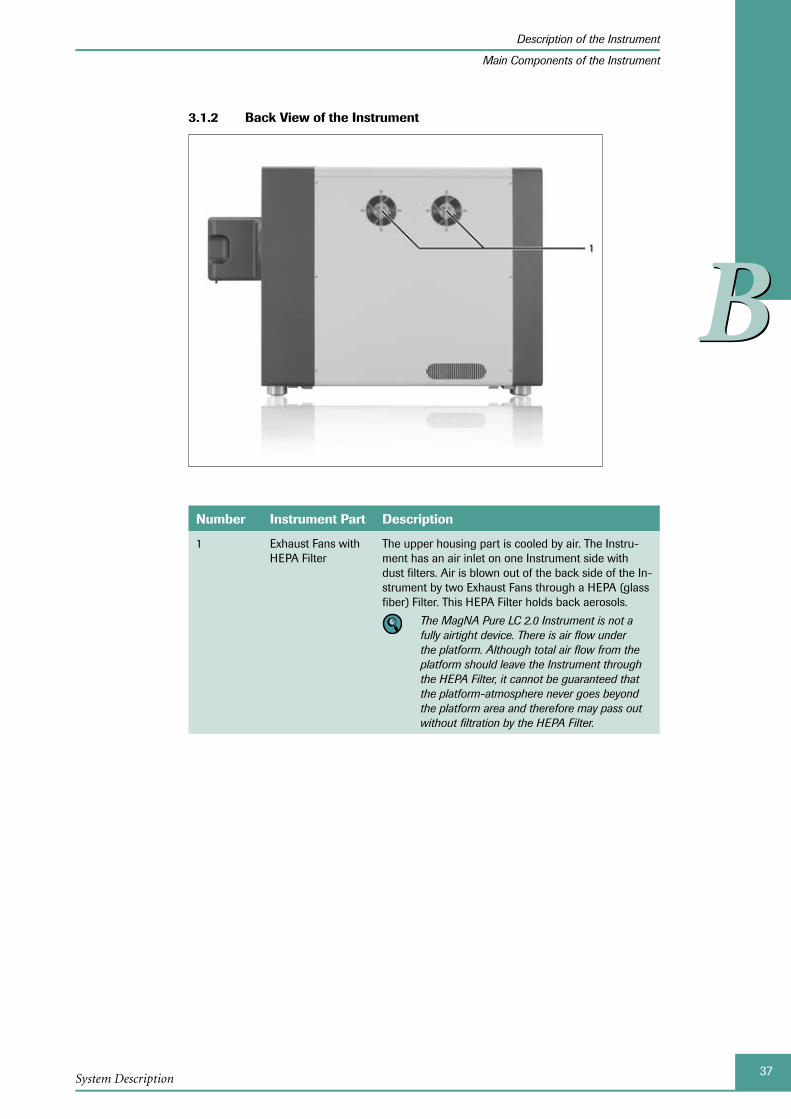
37System Description
Description of the Instrument
Main Components of the Instrument
BB
3.1.2 Back View of the Instrument
Number Instrument Part Description
1 Exhaust Fans with HEPA Filter
The upper housing part is cooled by air. The Instru-ment has an air inlet on one Instrument side with dust filters. Air is blown out of the back side of the In-strument by two Exhaust Fans through a HEPA (glass fiber) Filter. This HEPA Filter holds back aerosols.
The MagNA Pure LC 2.0 Instrument is not a fully airtight device. There is air flow under the platform. Although total air flow from the platform should leave the Instrument through the HEPA Filter, it cannot be guaranteed that the platform-atmosphere never goes beyond the platform area and therefore may pass out without filtration by the HEPA Filter.
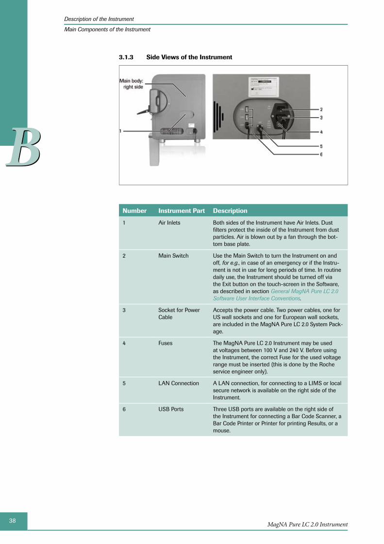
38MagNA Pure LC 2.0 Instrument
Description of the Instrument
Main Components of the Instrument
BB
Side Views of the 3.1.3 Instrument
Number Instrument Part Description
1 Air Inlets Both sides of the Instrument have Air Inlets. Dust filters protect the inside of the Instrument from dust particles. Air is blown out by a fan through the bot-tom base plate.
2 Main Switch Use the Main Switch to turn the Instrument on and off, for e.g., in case of an emergency or if the Instru-ment is not in use for long periods of time. In routine daily use, the Instrument should be turned off via the Exit button on the touch-screen in the Software, as described in section General MagNA Pure LC 2.0 Software User Interface Conventions.
3 Socket for Power Cable
Accepts the power cable. Two power cables, one for US wall sockets and one for European wall sockets, are included in the MagNA Pure LC 2.0 System Pack-age.
4 Fuses The MagNA Pure LC 2.0 Instrument may be used at voltages between 100 V and 240 V. Before using the Instrument, the correct Fuse for the used voltage range must be inserted (this is done by the Roche service engineer only).
5 LAN Connection A LAN connection, for connecting to a LIMS or local secure network is available on the right side of the Instrument.
6 USB Ports Three USB ports are available on the right side of the Instrument for connecting a Bar Code Scanner, a Bar Code Printer or Printer for printing Results, or a mouse.
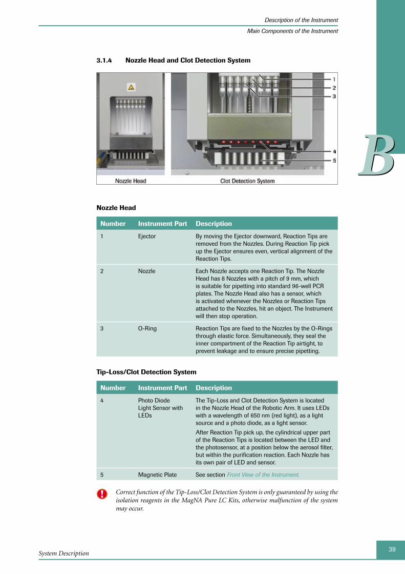
39System Description
Description of the Instrument
Main Components of the Instrument
BB
3.1.4 Nozzle Head and Clot Detection System
Nozzle Head
Number Instrument Part Description
1 Ejector By moving the Ejector downward, Reaction Tips are removed from the Nozzles. During Reaction Tip pick up the Ejector ensures even, vertical alignment of the Reaction Tips.
2 Nozzle Each Nozzle accepts one Reaction Tip. The Nozzle Head has 8 Nozzles with a pitch of 9 mm, which is suitable for pipetting into standard 96-well PCR plates. The Nozzle Head also has a sensor, which is activated whenever the Nozzles or Reaction Tips attached to the Nozzles, hit an object. The Instrument will then stop operation.
3 O-Ring Reaction Tips are fixed to the Nozzles by the O-Rings through elastic force. Simultaneously, they seal the inner compartment of the Reaction Tip airtight, to prevent leakage and to ensure precise pipetting.
Tip-Loss/Clot Detection System
Number Instrument Part Description
4 Photo Diode Light Sensor with LEDs
The Tip-Loss and Clot Detection System is located in the Nozzle Head of the Robotic Arm. It uses LEDs with a wavelength of 650 nm (red light), as a light source and a photo diode, as a light sensor.
After Reaction Tip pick up, the cylindrical upper part of the Reaction Tips is located between the LED and the photosensor, at a position below the aerosol filter, but within the purification reaction. Each Nozzle has its own pair of LED and sensor.
5 Magnetic Plate See section Front View of the Instrument.
Correct function of the Tip-Loss/Clot Detection System is only guaranteed by using the isolation reagents in the MagNA Pure LC Kits, otherwise malfunction of the system may occur.
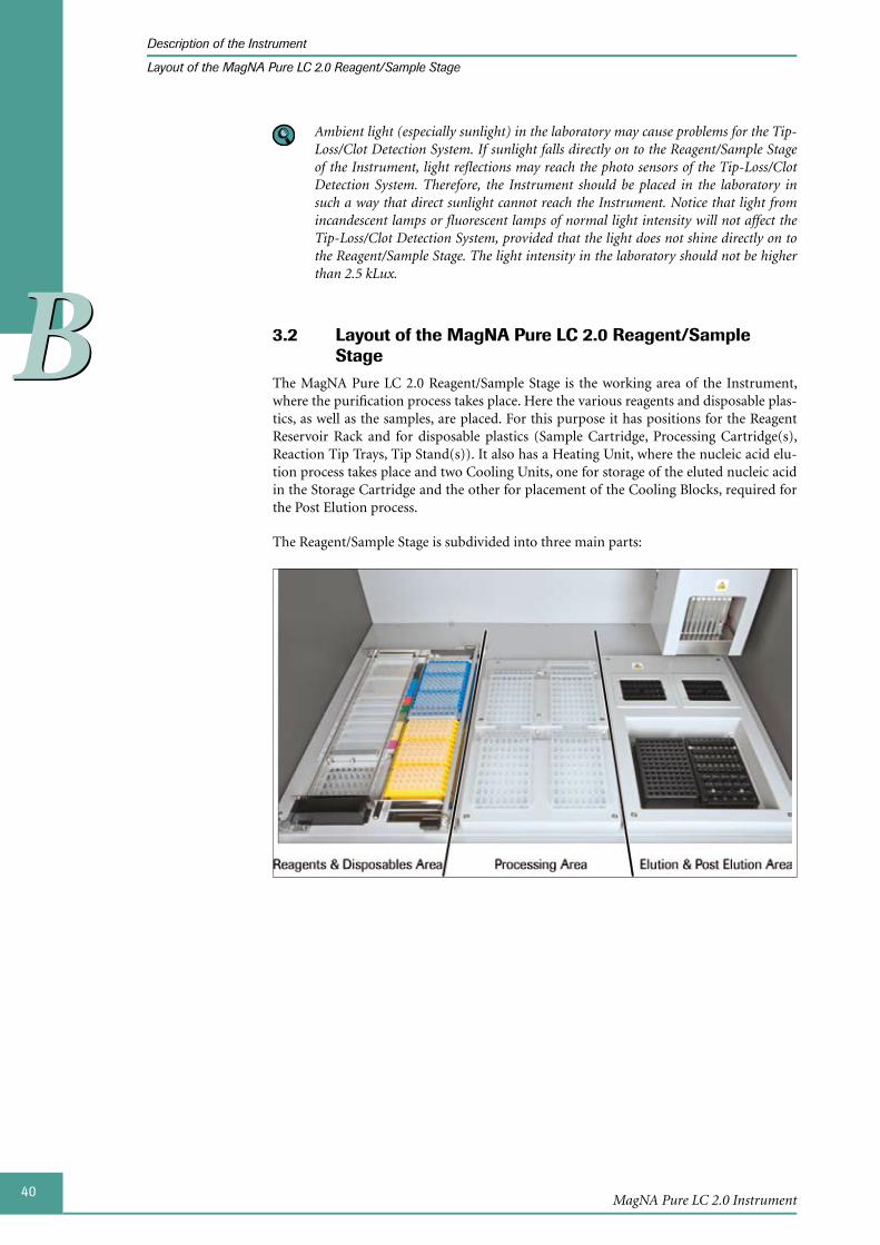
40MagNA Pure LC 2.0 Instrument
Description of the Instrument
Layout of the MagNA Pure LC 2.0 Reagent/Sample Stage
BB
Ambient light (especially sunlight) in the laboratory may cause problems for the Tip-Loss/Clot Detection System. If sunlight falls directly on to the Reagent/Sample Stage of the Instrument, light reflections may reach the photo sensors of the Tip-Loss/Clot Detection System. Therefore, the Instrument should be placed in the laboratory in such a way that direct sunlight cannot reach the Instrument. Notice that light from incandescent lamps or fluorescent lamps of normal light intensity will not affect the Tip-Loss/Clot Detection System, provided that the light does not shine directly on to the Reagent/Sample Stage. The light intensity in the laboratory should not be higher than 2.5 kLux.
3.2 Layout of the MagNA Pure LC 2.0 Reagent/Sample Stage
The MagNA Pure LC 2.0 Reagent/Sample Stage is the working area of the Instrument, where the purification process takes place. Here the various reagents and disposable plas-tics, as well as the samples, are placed. For this purpose it has positions for the Reagent Reservoir Rack and for disposable plastics (Sample Cartridge, Processing Cartridge(s), Reaction Tip Trays, Tip Stand(s)). It also has a Heating Unit, where the nucleic acid elu-tion process takes place and two Cooling Units, one for storage of the eluted nucleic acid in the Storage Cartridge and the other for placement of the Cooling Blocks, required for the Post Elution process.
The Reagent/Sample Stage is subdivided into three main parts:
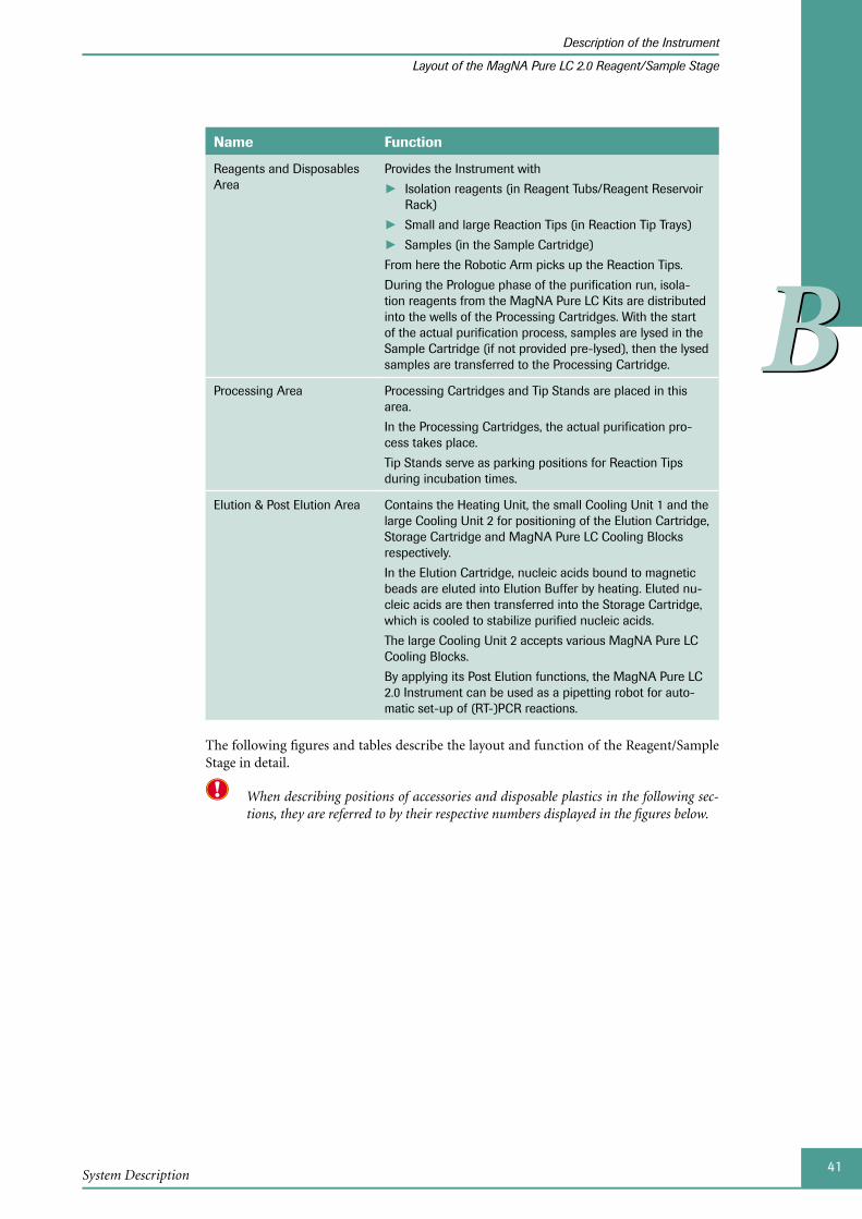
41System Description
Description of the Instrument
Layout of the MagNA Pure LC 2.0 Reagent/Sample Stage
BB
Name Function
Reagents and Disposables Area
Provides the Instrument with
Isolation reagents (in Reagent Tubs/Reagent Reservoir ►Rack)
Small and large Reaction Tips (in Reaction Tip Trays) ►Samples (in the Sample Cartridge) ►
From here the Robotic Arm picks up the Reaction Tips.
During the Prologue phase of the purification run, isola-tion reagents from the MagNA Pure LC Kits are distributed into the wells of the Processing Cartridges. With the start of the actual purification process, samples are lysed in the Sample Cartridge (if not provided pre-lysed), then the lysed samples are transferred to the Processing Cartridge.
Processing Area Processing Cartridges and Tip Stands are placed in this area.
In the Processing Cartridges, the actual purification pro-cess takes place.
Tip Stands serve as parking positions for Reaction Tips during incubation times.
Elution & Post Elution Area Contains the Heating Unit, the small Cooling Unit 1 and the large Cooling Unit 2 for positioning of the Elution Cartridge, Storage Cartridge and MagNA Pure LC Cooling Blocks respectively.
In the Elution Cartridge, nucleic acids bound to magnetic beads are eluted into Elution Buffer by heating. Eluted nu-cleic acids are then transferred into the Storage Cartridge, which is cooled to stabilize purified nucleic acids.
The large Cooling Unit 2 accepts various MagNA Pure LC Cooling Blocks.
By applying its Post Elution functions, the MagNA Pure LC 2.0 Instrument can be used as a pipetting robot for auto-matic set-up of (RT-)PCR reactions.
The following figures and tables describe the layout and function of the Reagent/Sample Stage in detail.
When describing positions of accessories and disposable plastics in the following sec-tions, they are referred to by their respective numbers displayed in the figures below.
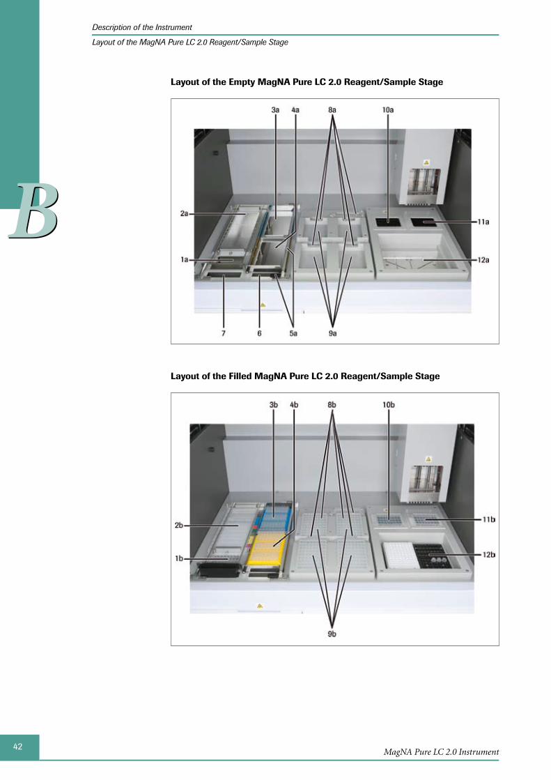
42MagNA Pure LC 2.0 Instrument
Description of the Instrument
Layout of the MagNA Pure LC 2.0 Reagent/Sample Stage
BB
Layout of the Empty MagNA Pure LC 2.0 Reagent/Sample Stage
Layout of the Filled MagNA Pure LC 2.0 Reagent/Sample Stage
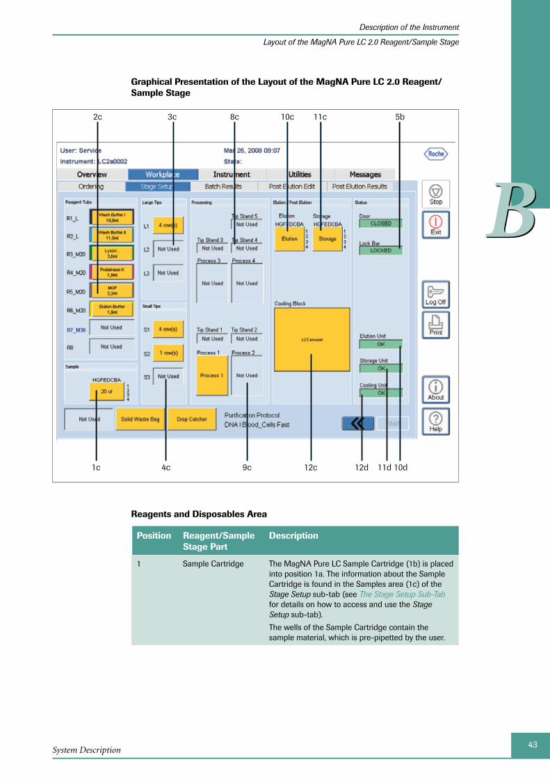
43System Description
Description of the Instrument
Layout of the MagNA Pure LC 2.0 Reagent/Sample Stage
BB
Graphical Presentation of the Layout of the MagNA Pure LC 2.0 Reagent/Sample Stage
1c 4c 9c 12c
2c 3c 8c 10c 11c 5b
10d11d12d
Reagents and Disposables Area
Position Reagent/Sample Stage Part
Description
1 Sample Cartridge The MagNA Pure LC Sample Cartridge (1b) is placed into position 1a. The information about the Sample Cartridge is found in the Samples area (1c) of the Stage Setup sub-tab (see The Stage Setup Sub-Tab for details on how to access and use the Stage Setup sub-tab).
The wells of the Sample Cartridge contain the sample material, which is pre-pipetted by the user.

44MagNA Pure LC 2.0 Instrument
Description of the Instrument
Layout of the MagNA Pure LC 2.0 Reagent/Sample Stage
BB
Position Reagent/Sample Stage Part
Description
2 Reagent Tubs The MagNA Pure LC Reagent Reservoir Rack (2b) is placed into position 2a. It holds the MagNA Pure LC Reagent Tubs, which hold the isolation reagents and buffers from the MagNA Pure LC Kits. Four different types of Reagent Tubs are available: Large; medium 20; medium 30 and small (see section Disposable Plastics for the MagNA Pure LC 2.0 Instrument for a detailed description of disposable plastics). The type of Reagent Tub, that must be placed in the Reagent Reservoir Rack and the type and volume of buffer to be pipetted into the Reagent Tubs is displayed in the Reagent Tubs area on the Stage Setup sub-tab (2c).
See section Filling and Placing the MagNA Pure LC Reagent Tubs (Stage Position 2) for details on how to fill and place Reagent Tubs on the Reagent/Sample Stage.
3 Large Reaction Tips The inbuilt Tip Rack for the Large Reaction Tips is position 3a. The Tip Rack is filled with Large Reac-tion Tips pre-packed in Reaction Tip Trays (3b), according to the information displayed in the Large Tips area on the Stage Setup sub-tab (3c). Large Reaction Tips and their trays are colored blue.
See Placing the MagNA Pure LC Reaction Tips (Stage Position 3/4) for details on how to place Large Reac-tion Tips on the Reagent/Sample Stage.
4 Small Reaction Tips The inbuilt Tip Rack for the Small Reaction Tips is position 4a. The Tip Rack is filled with Small Reac-tion Tips pre-packed in Reaction Tip Trays (4b), according to the information displayed in the Small Tips area on the Stage Setup sub-tab (4c). Small Reaction Tips and their trays are colored yellow.
See Placing the MagNA Pure LC Reaction Tips (Stage Position 3/4) for details on how to place Small Reac-tion Tips on the Reagent/Sample Stage.
5 Disposable Lock Bar The Disposable Lock Bar holds the disposable plas-tics in their correct positions on the Reagent/Sample Stage. The Sample Cartridge, Reagent Reservoir Rack and Reaction Tip Trays can only be placed after opening the Disposable Lock Bar. Starting a purification run is only possible after closing the Disposable Lock Bar. The status of the Disposable Lock Bar is indicated by the Lock Bar Status Indica-tor in the Status area on the Stage Setup sub-tab (5b).
6 Tip Waste Disposal Hole
Used Reaction Tips are discarded through the Tip Waste Disposal Hole (6) and the Tip Waste Slide into the Waste Bag within the Waste Box.
7 Liquid Waste Funnel Isolation reagents and buffers left in the wells of the Processing Cartridges, after completion of a purifica-tion run can optionally be discarded into the MagNA Pure LC Waste Bottle. The Liquid Waste Funnel transports the liquid waste into the Waste Bottle.

45System Description
Description of the Instrument
Layout of the MagNA Pure LC 2.0 Reagent/Sample Stage
BB
Processing Area
Position Reagent/Sample Stage Part
Description
8 Tip Stands There are 5 positions (8a) on the Reagent/Sample Stage for the MagNA Pure LC Tip Stands (8b). Behind each of the four Processing Cartridges there is one accompanying Tip Stand. During a purification run these Tip Stands temporarily store Reaction Tips, which are currently not in use, due to an incubation period. An additional fifth Tip Stand is located behind Tip Stand 4, which stores Reaction Tips, if sample numbers that are not divisible by eight are pro-cessed. The number and position of the Tip Stands is displayed in the Processing area on the Stage Setup sub-tab (8c).
See Placing the MagNA Pure LC Tip Stands (Stage Position 8) for details on how to place Tip Stands on the Reagent/Sample Stage.
9 Processing Cartridge
The MagNA Pure LC Processing Cartridges (9b) are placed into four identical positions in the center of the Reagent/Sample Stage (9a). The actual purifica-tion process takes place in the wells of the Process-ing Cartridges. The number of Processing Cartridges depends on the sample number: For every 8 samples, one Processing Cartridge is required. The number and position of the Processing Cartridges is shown in the Processing area on the Stage Setup sub-tab (9c).
See Placing the MagNA Pure LC Processing Car-tridges (Stage Position 9) for details on how to place Processing Cartridges on the Reagent/Sample Stage.

46MagNA Pure LC 2.0 Instrument
Description of the Instrument
Layout of the MagNA Pure LC 2.0 Reagent/Sample Stage
BB
Elution and Post Elution Area
Position Reagent/Sample Stage Part
Description
10 Heating Unit The Heating Unit (10a) is heated to 60°C (dur-ing stand-by) or to 80 to 90°C (during operation, depending on the purification protocol used) by a Peltier element. A MagNA Pure LC Sample Cartridge (10b), as an Elution Cartridge is placed into the Heating Unit. Inside the wells of the Elution Cartridge, elution of isolated nucleic acids from the magnetic beads in Elution Buffer takes place. The temperature status of the Heating Unit is shown by the Elution Unit Status Indicator in the Status area on the Stage Setup sub-tab (10d).
See Placing the Elution Cartridge and the Storage Cartridge (Stage Position 10/11) for details on how to place the Elution Cartridge into the Heating Unit.
11 Cooling Unit 1 Cooling Unit 1 (11a) is cooled to 7.5°C by a Peltier element. Into Cooling Unit 1, a MagNA Pure LC Sample Cartridge (11b), as a Storage Cartridge is placed, into which the purified nucleic acid samples are eluted. The temperature status of Cooling Unit 1 is shown by the Storage Unit Status Indicator in the Status area on the Stage Setup sub-tab (11d).
See Placing the Elution Cartridge and the Storage Cartridge (Stage Position 10/11) for details on how to place the Storage Cartridge into Cooling Unit 1.
12 Cooling Unit 2 Cooling Unit 2 (12a) is cooled to 7.5°C by a Peltier element. Cooling Unit 2 is suitable for the placing of user exchangeable MagNA Pure LC Cooling Blocks (12b: e.g., LC Centrifuge Adapters Cooling Block), which are used during the Post Elution process for set-up of (RT-)PCR reactions. The temperature status of Cooling Unit 2 is shown by the Cooling Unit Status Indicator in the Status area on the Stage Setup sub-tab (12d).
The appropriate MagNA Pure LC Cooling Block is shown on the ‘Stage Setup’ sub-tab (12c), only if a Post Elution protocol is de-fined during Sample Ordering.
See section MagNA Pure LC 2.0 Accessories for a description of the MagNA Pure LC Cooling Blocks and Positioning MagNA Pure LC Cooling Blocks for a description on how to place them into Cooling Unit 2.
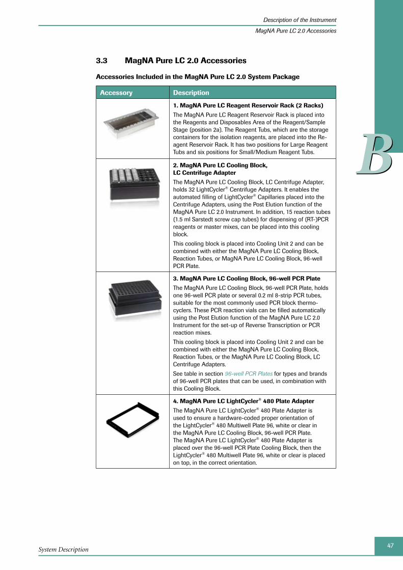
47System Description
Description of the Instrument
MagNA Pure LC 2.0 Accessories
BB
MagNA Pure LC 2.0 Accessories3.3
Accessories Included in the MagNA Pure LC 2.0 System Package
Accessory Description
1. MagNA Pure LC Reagent Reservoir Rack (2 Racks)
The MagNA Pure LC Reagent Reservoir Rack is placed into the Reagents and Disposables Area of the Reagent/Sample Stage (position 2a). The Reagent Tubs, which are the storage containers for the isolation reagents, are placed into the Re-agent Reservoir Rack. It has two positions for Large Reagent Tubs and six positions for Small/Medium Reagent Tubs.
2. MagNA Pure LC Cooling Block, LC Centrifuge Adapter
The MagNA Pure LC Cooling Block, LC Centrifuge Adapter, holds 32 LightCycler® Centrifuge Adapters. It enables the automated filling of LightCycler® Capillaries placed into the Centrifuge Adapters, using the Post Elution function of the MagNA Pure LC 2.0 Instrument. In addition, 15 reaction tubes (1.5 ml Sarstedt screw cap tubes) for dispensing of (RT-)PCR reagents or master mixes, can be placed into this cooling block.
This cooling block is placed into Cooling Unit 2 and can be combined with either the MagNA Pure LC Cooling Block, Reaction Tubes, or MagNA Pure LC Cooling Block, 96-well PCR Plate.
3. MagNA Pure LC Cooling Block, 96-well PCR Plate
The MagNA Pure LC Cooling Block, 96-well PCR Plate, holds one 96-well PCR plate or several 0.2 ml 8-strip PCR tubes, suitable for the most commonly used PCR block thermo-cyclers. These PCR reaction vials can be filled automatically using the Post Elution function of the MagNA Pure LC 2.0 Instrument for the set-up of Reverse Transcription or PCR reaction mixes.
This cooling block is placed into Cooling Unit 2 and can be combined with either the MagNA Pure LC Cooling Block, Reaction Tubes, or the MagNA Pure LC Cooling Block, LC Centrifuge Adapters.
See table in section 96-well PCR Plates for types and brands of 96-well PCR plates that can be used, in combination with this Cooling Block.
4. MagNA Pure LC LightCycler® 480 Plate Adapter
The MagNA Pure LC LightCycler® 480 Plate Adapter is used to ensure a hardware-coded proper orientation of the LightCycler® 480 Multiwell Plate 96, white or clear in the MagNA Pure LC Cooling Block, 96-well PCR Plate. The MagNA Pure LC LightCycler® 480 Plate Adapter is placed over the 96-well PCR Plate Cooling Block, then the LightCycler® 480 Multiwell Plate 96, white or clear is placed on top, in the correct orientation.
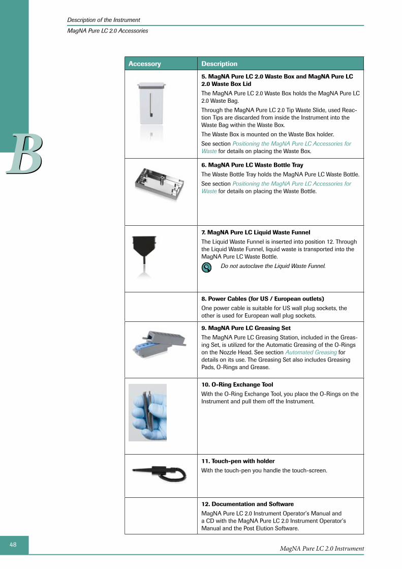
48MagNA Pure LC 2.0 Instrument
Description of the Instrument
MagNA Pure LC 2.0 Accessories
BB
Accessory Description
5. MagNA Pure LC 2.0 Waste Box and MagNA Pure LC 2.0 Waste Box Lid
The MagNA Pure LC 2.0 Waste Box holds the MagNA Pure LC 2.0 Waste Bag.
Through the MagNA Pure LC 2.0 Tip Waste Slide, used Reac-tion Tips are discarded from inside the Instrument into the Waste Bag within the Waste Box.
The Waste Box is mounted on the Waste Box holder.
See section Positioning the MagNA Pure LC Accessories for Waste for details on placing the Waste Box.
6. MagNA Pure LC Waste Bottle Tray
The Waste Bottle Tray holds the MagNA Pure LC Waste Bottle.
See section Positioning the MagNA Pure LC Accessories for Waste for details on placing the Waste Bottle.
7. MagNA Pure LC Liquid Waste Funnel
The Liquid Waste Funnel is inserted into position 12. Through the Liquid Waste Funnel, liquid waste is transported into the MagNA Pure LC Waste Bottle.
Do not autoclave the Liquid Waste Funnel.
8. Power Cables (for US / European outlets)
One power cable is suitable for US wall plug sockets, the other is used for European wall plug sockets.
9. MagNA Pure LC Greasing Set
The MagNA Pure LC Greasing Station, included in the Greas-ing Set, is utilized for the Automatic Greasing of the O-Rings on the Nozzle Head. See section Automated Greasing for details on its use. The Greasing Set also includes Greasing Pads, O-Rings and Grease.
10. O-Ring Exchange Tool
With the O-Ring Exchange Tool, you place the O-Rings on the Instrument and pull them off the Instrument.
11. Touch-pen with holder
With the touch-pen you handle the touch-screen.
12. Documentation and Software
MagNA Pure LC 2.0 Instrument Operator’s Manual and a CD with the MagNA Pure LC 2.0 Instrument Operator’s Manual and the Post Elution Software.
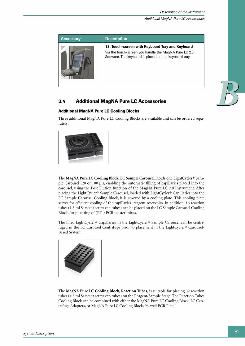
49System Description
Description of the Instrument
Additional MagNA Pure LC Accessories
BB
Accessory Description
13. Touch-screen with Keyboard Tray and Keyboard
Via the touch-screen you handle the MagNA Pure LC 2.0 Software. The keyboard is placed on the keyboard tray.
Additional MagNA Pure LC 3.4 Accessories
Additional MagNA Pure LC Cooling Blocks
Three additional MagNA Pure LC Cooling Blocks are available and can be ordered sepa-rately:
The MagNA Pure LC Cooling Block, LC Sample Carousel, holds one LightCycler® Sam-ple Carousel (20 or 100 µl), enabling the automatic filling of capillaries placed into the carousel, using the Post Elution function of the MagNA Pure LC 2.0 Instrument. After placing the LightCycler® Sample Carousel, loaded with LightCycler® Capillaries into the LC Sample Carousel Cooling Block, it is covered by a cooling plate. This cooling plate serves for efficient cooling of the capillaries´ reagent reservoirs. In addition, 16 reaction tubes (1.5 ml Sarstedt screw cap tubes) can be placed on the LC Sample Carousel Cooling Block, for pipetting of (RT-) PCR master mixes.
The filled LightCycler® Capillaries in the LightCycler® Sample Carousel can be centri-fuged in the LC Carousel Centrifuge prior to placement in the LightCycler® Carousel-Based System.
The MagNA Pure LC Cooling Block, Reaction Tubes, is suitable for placing 32 reaction tubes (1.5 ml Sarstedt screw cap tubes) on the Reagent/Sample Stage. The Reaction Tubes Cooling Block can be combined with either the MagNA Pure LC Cooling Block, LC Cen-trifuge Adapters, or MagNA Pure LC Cooling Block, 96-well PCR Plate.

50MagNA Pure LC 2.0 Instrument
Description of the Instrument
Additional MagNA Pure LC Accessories
BBThe MagNA Pure LC Cooling Block, A-Ring, is suitable for holding two COBAS® AmpliCor® A-Rings with 12 reaction vessels each.
The A-Ring Cooling Block provides two sets of 12 holes each, for positioning of the A-Ring reaction vessels and lids. It also has two positions for placement of the A-Ring support in-cluding the bar code. In addition, four Large and four Small COBAS® AmpliCor® reagent tubes can be placed for dispensing of PCR reagents.
These additional MagNA Pure LC Cooling Blocks, as well as those MagNA Pure LC Cool-ing Blocks included in the MagNA Pure LC 2.0 System Package and some of the accesso-ries described above, may be ordered separately. For more information, see section Order-ing Information.
See section 96-well PCR Plates for types and brands of PCR plates, that have been tested and which can be used in combination with the 96-well PCR Plate Cooling Block.
Cooling Block Catalog Number Pack Size
MagNA Pure LC Cooling Block, LC Centrifuge Adapters*
12 190 664 001 1 cooling block with 32 LightCycler® Centrifuge Adapters
MagNA Pure LC Cooling Block, 96-well PCR Plate*
12 189 674 001 1 cooling block
MagNA Pure LC Cooling Block, LC Sample Carousel
12 189 704 001 1 cooling block
MagNA Pure LC Cooling Block, Reaction Tubes
12 189 666 001 1 cooling block
MagNA Pure LC Cooling Block, A-Ring
03 201 287 001 1 cooling block
Accessories Catalog Number Pack Size
MagNA Pure LC LightCycler® 480 Plate Adapter*
05 323 983 001 1 adapter
MagNA Pure LC Reagent Reservoir Rack*
03 253 767 001 1 rack
MagNA Pure LC 2.0 Tip Waste Slide* 05 324 122 001 1 slide
MagNA Pure LC Liquid Waste Funnel* 03 253 805 001 1 funnel
MagNA Pure LC Waste Bottle Tray* 03 253 813 001 1 tray
MagNA Pure LC 2.0 Waste Box* 05 323 991 001 1 box
MagNA Pure LC 2.0 Waste Box Lid* 05 324 114 001 1 lid
* Included in the MagNA Pure LC 2.0 System Package
51System Description
Disposable Plastics for the MagNA Pure LC 2.0 Instrument
BB
4 Disposable Plastics for the MagNA Pure LC 2.0 Instrument
For operation, the MagNA Pure LC 2.0 Instrument requires specific disposable plastics. These are used e.g., either for holding samples or isolation reagents (Sample Cartridge, Reagent Tubs), or during the actual purification process (Reaction Tips, Processing Car-tridges, Elution/Storage Cartridge).
The MagNA Pure LC disposable plastics meet the stringent demands of RT-PCR and PCR. They are guaranteed to be inert to most chemicals used in laboratory settings and nucle-ase-free. The production process excludes any biological contamination.
All the disposable plastics (except for the Waste Bags and Waste Bottles) are sterilized by E-beam. The units are subdivided and packaged in separate, nuclease-free bags to avoid contamination after opening the box. The expiration date and proof of sterilization are stamped on the box.
The MagNA Pure LC disposable plastics are intended for single use only. Never use a disposable plastic several times (even after possibly cleaning it). This would inevitably lead to unexpected and unreliable results.
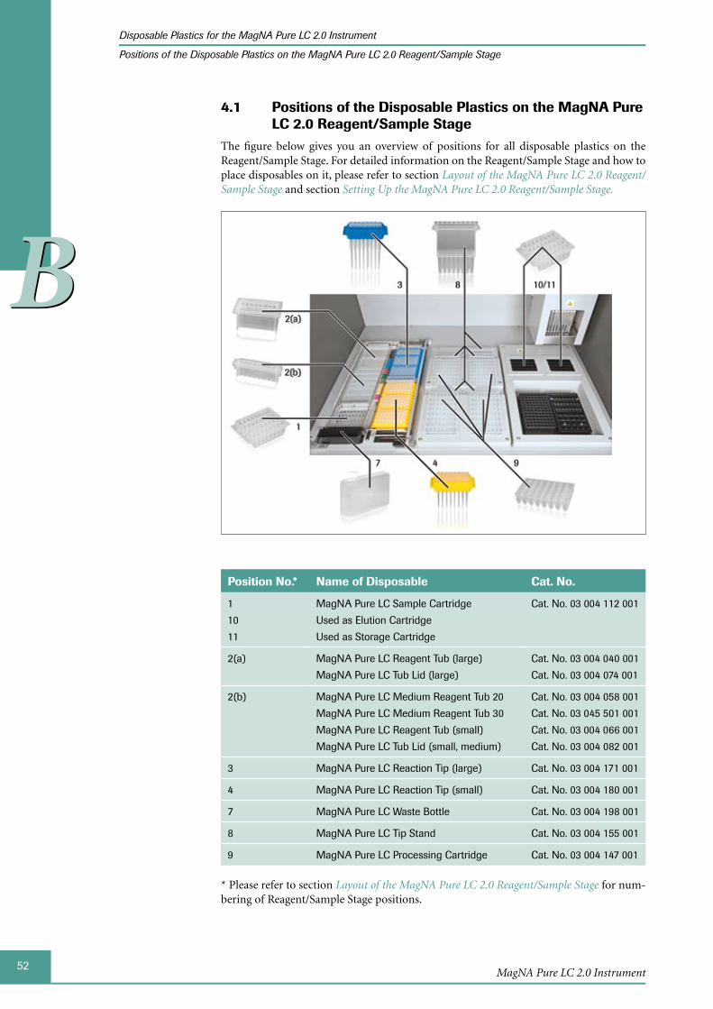
52MagNA Pure LC 2.0 Instrument
Disposable Plastics for the MagNA Pure LC 2.0 Instrument
Positions of the Disposable Plastics on the MagNA Pure LC 2.0 Reagent/Sample Stage
BB
Positions of 4.1 the Disposable Plastics on the MagNA Pure LC 2.0 Reagent/Sample Stage
The figure below gives you an overview of positions for all disposable plastics on the Reagent/Sample Stage. For detailed information on the Reagent/Sample Stage and how to place disposables on it, please refer to section Layout of the MagNA Pure LC 2.0 Reagent/Sample Stage and section Setting Up the MagNA Pure LC 2.0 Reagent/Sample Stage.
Position No.* Name of Disposable Cat. No.
1
10
11
MagNA Pure LC Sample Cartridge
Used as Elution Cartridge
Used as Storage Cartridge
Cat. No. 03 004 112 001
2(a) MagNA Pure LC Reagent Tub (large)
MagNA Pure LC Tub Lid (large)
Cat. No. 03 004 040 001
Cat. No. 03 004 074 001
2(b) MagNA Pure LC Medium Reagent Tub 20
MagNA Pure LC Medium Reagent Tub 30
MagNA Pure LC Reagent Tub (small)
MagNA Pure LC Tub Lid (small, medium)
Cat. No. 03 004 058 001
Cat. No. 03 045 501 001
Cat. No. 03 004 066 001
Cat. No. 03 004 082 001
3 MagNA Pure LC Reaction Tip (large) Cat. No. 03 004 171 001
4 MagNA Pure LC Reaction Tip (small) Cat. No. 03 004 180 001
7 MagNA Pure LC Waste Bottle Cat. No. 03 004 198 001
8 MagNA Pure LC Tip Stand Cat. No. 03 004 155 001
9 MagNA Pure LC Processing Cartridge Cat. No. 03 004 147 001
* Please refer to section Layout of the MagNA Pure LC 2.0 Reagent/Sample Stage for num-bering of Reagent/Sample Stage positions.
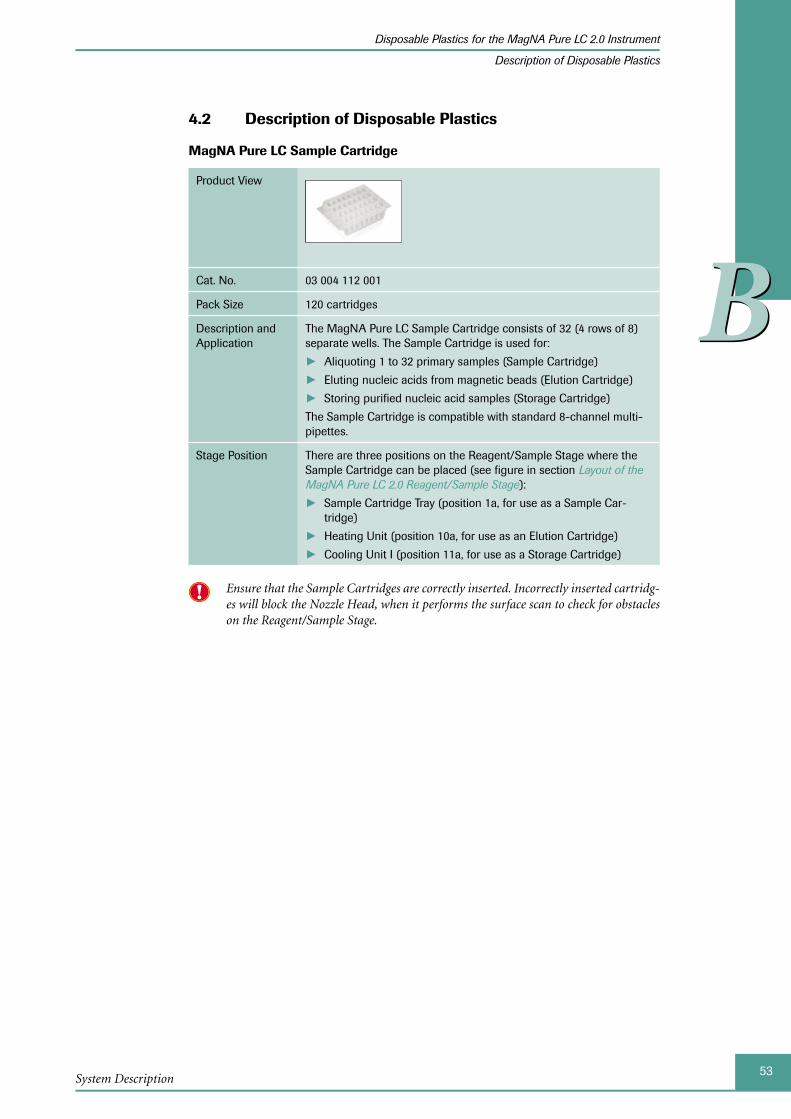
53System Description
Disposable Plastics for the MagNA Pure LC 2.0 Instrument
Description of Disposable Plastics
BB
Description of Disposable Plastics4.2
MagNA Pure LC Sample Cartridge
Product View
Cat. No. 03 004 112 001
Pack Size 120 cartridges
Description and Application
The MagNA Pure LC Sample Cartridge consists of 32 (4 rows of 8) separate wells. The Sample Cartridge is used for:
Aliquoting 1 to 32 primary samples (Sample Cartridge) ►Eluting nucleic acids from magnetic beads (Elution Cartridge) ►Storing purified nucleic acid samples (Storage Cartridge) ►
The Sample Cartridge is compatible with standard 8-channel multi-pipettes.
Stage Position There are three positions on the Reagent/Sample Stage where the Sample Cartridge can be placed (see figure in section Layout of the MagNA Pure LC 2.0 Reagent/Sample Stage):
Sample Cartridge Tray (position 1a, for use as a Sample Car- ►tridge)
Heating Unit (position 10a, for use as an Elution Cartridge) ►Cooling Unit I (position 11a, for use as a Storage Cartridge) ►
Ensure that the Sample Cartridges are correctly inserted. Incorrectly inserted cartridg-es will block the Nozzle Head, when it performs the surface scan to check for obstacles on the Reagent/Sample Stage.

54MagNA Pure LC 2.0 Instrument
Disposable Plastics for the MagNA Pure LC 2.0 Instrument
Description of Disposable Plastics
BB
MagNA Pure LC Cartridge Seal
Product View
Cat. No. 03 118 827 001
Pack Size 200 seals (100 sheets with 2 seals per sheet)
Application The MagNA Pure LC Cartridge Seal is applied on to the MagNA Pure LC Sample Cartridges, in order to store the nucleic acids in the cartridge (Storage Cartridge). The film protects the isolated nucleic acids against evaporation and contamination. It allows airtight seal-ing of the Storage Cartridge within a temperature range of -70°C to room temperature. The Cartridge Seal has been tested for the absence of nucleases and inhibitors.
The film can be removed by carefully peeling from the cartridge.
Individual samples can be taken out of the cartridge by cutting the film above the respective well. The cartridge can then be re-sealed with a new Cartridge Seal.
Do not remove the Cartridge Seal too abruptly from the Storage Cartridge, because this may lead to cross contamination by creating aerosols and carry-over from well to well.
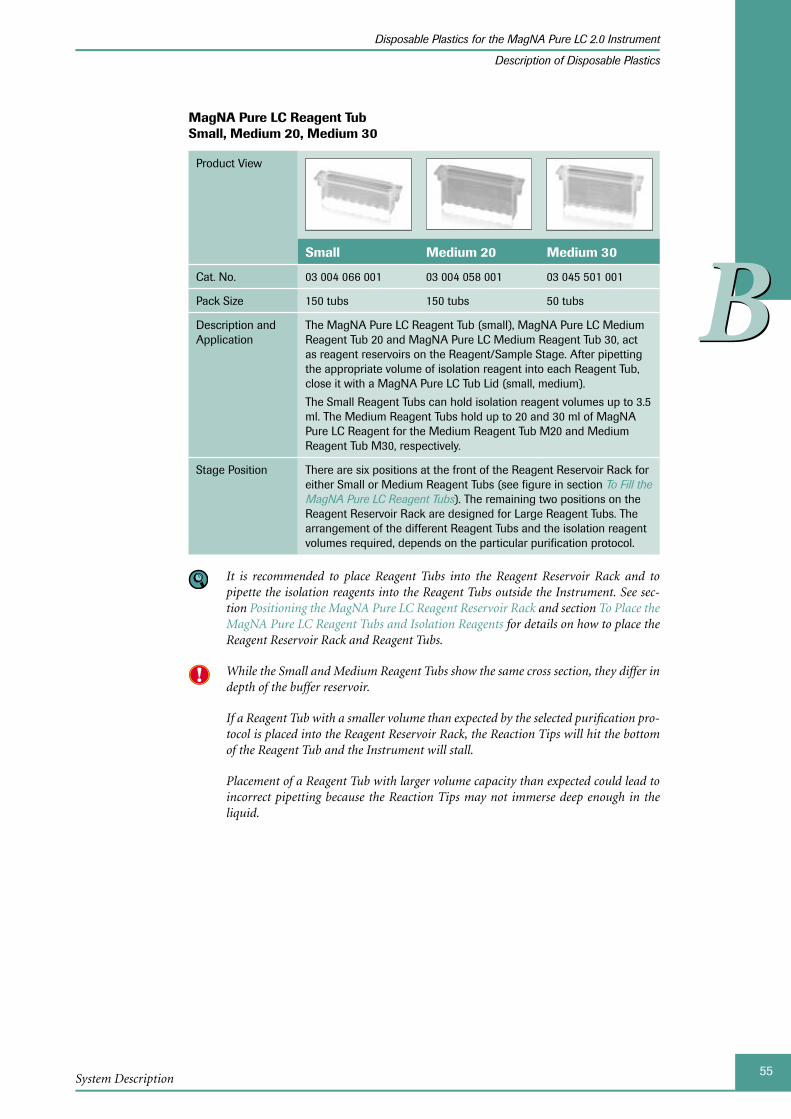
55System Description
Disposable Plastics for the MagNA Pure LC 2.0 Instrument
Description of Disposable Plastics
BB
MagNA Pure LC Reagent Tub Small, Medium 20, Medium 30
Product View
Small Medium 20 Medium 30
Cat. No. 03 004 066 001 03 004 058 001 03 045 501 001
Pack Size 150 tubs 150 tubs 50 tubs
Description and Application
The MagNA Pure LC Reagent Tub (small), MagNA Pure LC Medium Reagent Tub 20 and MagNA Pure LC Medium Reagent Tub 30, act as reagent reservoirs on the Reagent/Sample Stage. After pipetting the appropriate volume of isolation reagent into each Reagent Tub, close it with a MagNA Pure LC Tub Lid (small, medium).
The Small Reagent Tubs can hold isolation reagent volumes up to 3.5 ml. The Medium Reagent Tubs hold up to 20 and 30 ml of MagNA Pure LC Reagent for the Medium Reagent Tub M20 and Medium Reagent Tub M30, respectively.
Stage Position There are six positions at the front of the Reagent Reservoir Rack for either Small or Medium Reagent Tubs (see figure in section To Fill the MagNA Pure LC Reagent Tubs). The remaining two positions on the Reagent Reservoir Rack are designed for Large Reagent Tubs. The arrangement of the different Reagent Tubs and the isolation reagent volumes required, depends on the particular purification protocol.
It is recommended to place Reagent Tubs into the Reagent Reservoir Rack and to pipette the isolation reagents into the Reagent Tubs outside the Instrument. See sec-tion Positioning the MagNA Pure LC Reagent Reservoir Rack and section To Place the MagNA Pure LC Rea gent Tubs and Isolation Reagents for details on how to place the Reagent Reservoir Rack and Reagent Tubs.
While the Small and Medium Reagent Tubs show the same cross section, they differ in depth of the buffer reservoir.
If a Reagent Tub with a smaller volume than expected by the selected purification pro-tocol is placed into the Reagent Reservoir Rack, the Reaction Tips will hit the bottom of the Reagent Tub and the Instrument will stall.
Placement of a Reagent Tub with larger volume capacity than expected could lead to incorrect pipetting because the Reaction Tips may not immerse deep enough in the liquid.

56MagNA Pure LC 2.0 Instrument
Disposable Plastics for the MagNA Pure LC 2.0 Instrument
Description of Disposable Plastics
BB
MagNA Pure LC Reagent Tub (Large)
Product View
Cat. No. 03 004 040 001
Pack Size 120 tubs
Description and Application
The MagNA Pure LC Reagent Tub (large) acts as reagent reser-voirs on the Reagent/Sample Stage. After pipetting the appropriate volume of isolation reagent into each Reagent Tub, close it with a MagNA Pure LC Tub Lid (Large).
The Large Reagent Tubs hold up to 100 ml of MagNA Pure LC Reagent.
Stage Position There are two positions at the rear of the Reagent Reservoir Rack for Large Reagent Tubs (see figure in section To Fill the MagNA Pure LC Reagent Tubs). The remaining six positions on the Reagent Reservoir Rack are designed for Small or Medium Reagent Tubs. The arrangement of the different Reagent Tubs and the isolation reagent volumes required, depends on the isolation protocol.
It is recommended to place Reagent Tubs into the Reagent Reservoir Rack and to pi-pette the isolation reagents into the Reagent Tubs outside the Instrument. See sec-tion Positioning the MagNA Pure LC Reagent Reservoir Rack and section To Fill the MagNA Pure LC Reagent Tubs for details on how to place the Reagent Reservoir Rack and Reagent Tubs.
MagNA Pure LC Tub Lid (Small, Medium)
Product View
Cat. No. Cat. No. 03 004 082 001
Pack Size 300 lids
Description and Application
The MagNA Pure LC Tub Lid (Small, Medium) is placed on the Small and Medium Reagent Tubs after filling with isolation reagents, to reduce loss of isolation reagent volume by evaporation.
Some of the buffers contained in the MagNA Pure LC Kits contain alcohol. Therefore, it is necessary to close the Reagent Tubs with a Tub Lid to avoid evaporation. Evapora-tion in turn may lead to changes in buffer composition or volume, which might impair the purification result.

57System Description
Disposable Plastics for the MagNA Pure LC 2.0 Instrument
Description of Disposable Plastics
BB
MagNA Pure LC Tub Lid (Large)
Product View
Cat. No. Cat. No. 03 004 074 001
Pack Size 120 lids
Description and Application
The MagNA Pure LC Tub Lid (Large) is placed on the Large Reagent Tubs after filling with isolation reagents, to reduce loss of isolation reagent volume by evaporation.
Some of the buffers contained in the MagNA Pure LC Kits contain alcohol. Therefore, it is necessary to close the Reagent Tubs with a Tub Lid to avoid evaporation. Evapora-tion in turn may lead to changes in buffer composition or volume, which might impair the purification result.
MagNA Pure LC Tub Lid Seal
Product View
Cat. No. Cat. No. 03 004 104 001
Pack Size 400 seals
Description and Application
The MagNA Pure LC Tub Lid Seal is used as a Liquid Drop Catcher, which prevents contamination of the Reagent/Sample Stage during movement of the Robotic Arm. Additionally, the Tub Lid Seal is suit-able for sealing all MagNA Pure LC Reagent Tubs.
Stage Position The Tub Lid Seal is only found on the Reagent/Sample Stage as the Liquid Drop Catcher.
To use the Tub Lid Seal as an insert into the Liquid Drop Catcher, please follow the instructions in section Changing the Liquid Drop Catcher.
In the event that there is a delay in the start of a purification run, seal the Reagent Tubs with a Tub Lid Seal to prevent evaporation of the isolation reagents.
Reagents must be stored at room temperature to prevent crystallization, except the Proteinase K solution, which must be stored at 4°C.
Ensure that all isolation reagents are equilibrated to room temperature before starting the purification run and that the Tub Lid Seals are removed from the Reagent Tubs, prior to placing them on the Reagent/Sample Stage.
Magnetic Glass Particles should never be stored in the Reagent Tubs, because they sedi-ment and clump, as well, they are stored in alcohol, which easily evaporates.
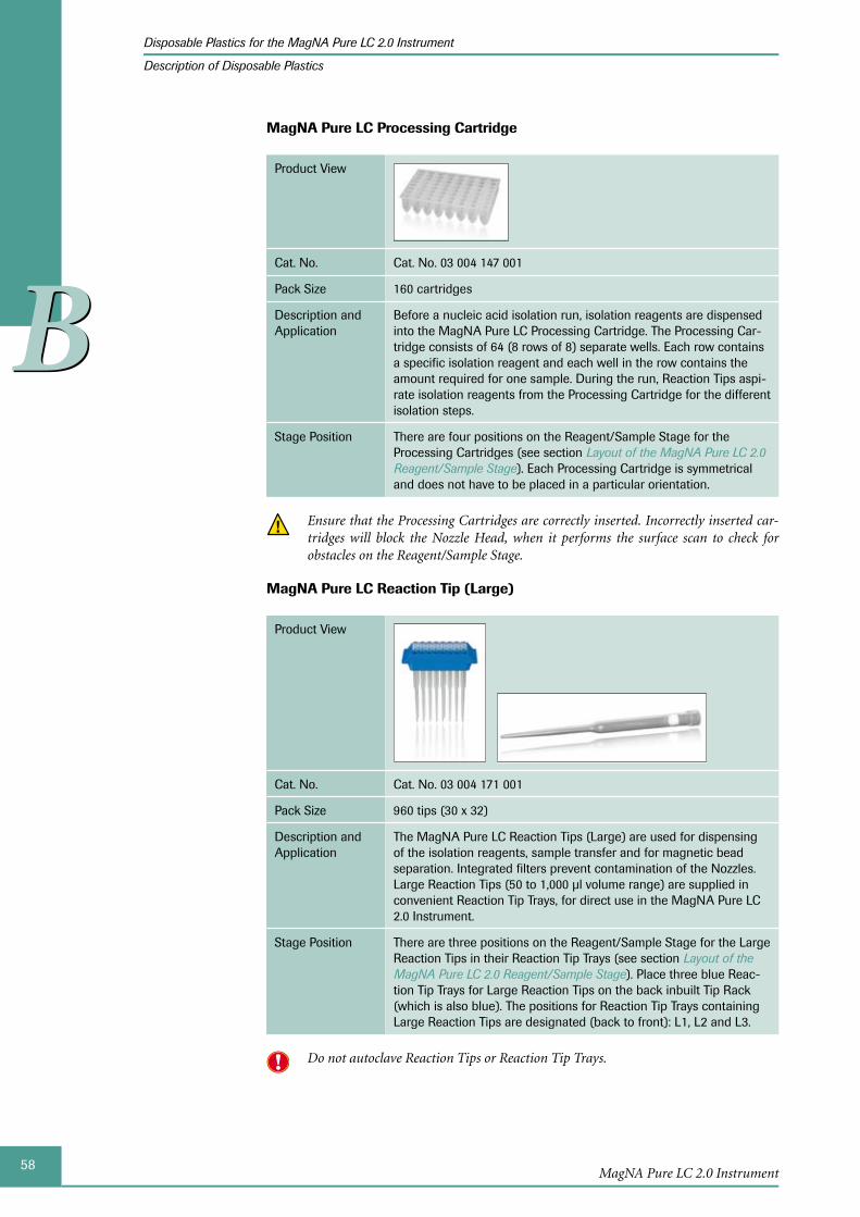
58MagNA Pure LC 2.0 Instrument
Disposable Plastics for the MagNA Pure LC 2.0 Instrument
Description of Disposable Plastics
BB
MagNA Pure LC Processing Cartridge
Product View
Cat. No. Cat. No. 03 004 147 001
Pack Size 160 cartridges
Description and Application
Before a nucleic acid isolation run, isolation reagents are dispensed into the MagNA Pure LC Processing Cartridge. The Processing Car-tridge consists of 64 (8 rows of 8) separate wells. Each row contains a specific isolation reagent and each well in the row contains the amount required for one sample. During the run, Reaction Tips aspi-rate isolation reagents from the Processing Cartridge for the different isolation steps.
Stage Position There are four positions on the Reagent/Sample Stage for the Processing Cartridges (see section Layout of the MagNA Pure LC 2.0 Reagent/Sample Stage). Each Processing Cartridge is symmetrical and does not have to be placed in a particular orientation.
Ensure that the Processing Cartridges are correctly inserted. Incorrectly inserted car-tridges will block the Nozzle Head, when it performs the surface scan to check for obstacles on the Reagent/Sample Stage.
MagNA Pure LC Reaction Tip (Large)
Product View
Cat. No. Cat. No. 03 004 171 001
Pack Size 960 tips (30 x 32)
Description and Application
The MagNA Pure LC Reaction Tips (Large) are used for dispensing of the isolation reagents, sample transfer and for magnetic bead separation. Integrated filters prevent contamination of the Nozzles. Large Reaction Tips (50 to 1,000 µl volume range) are supplied in convenient Reaction Tip Trays, for direct use in the MagNA Pure LC 2.0 Instrument.
Stage Position There are three positions on the Reagent/Sample Stage for the Large Reaction Tips in their Reaction Tip Trays (see section Layout of the MagNA Pure LC 2.0 Reagent/Sample Stage). Place three blue Reac-tion Tip Trays for Large Reaction Tips on the back inbuilt Tip Rack (which is also blue). The positions for Reaction Tip Trays containing Large Reaction Tips are designated (back to front): L1, L2 and L3.
Do not autoclave Reaction Tips or Reaction Tip Trays.
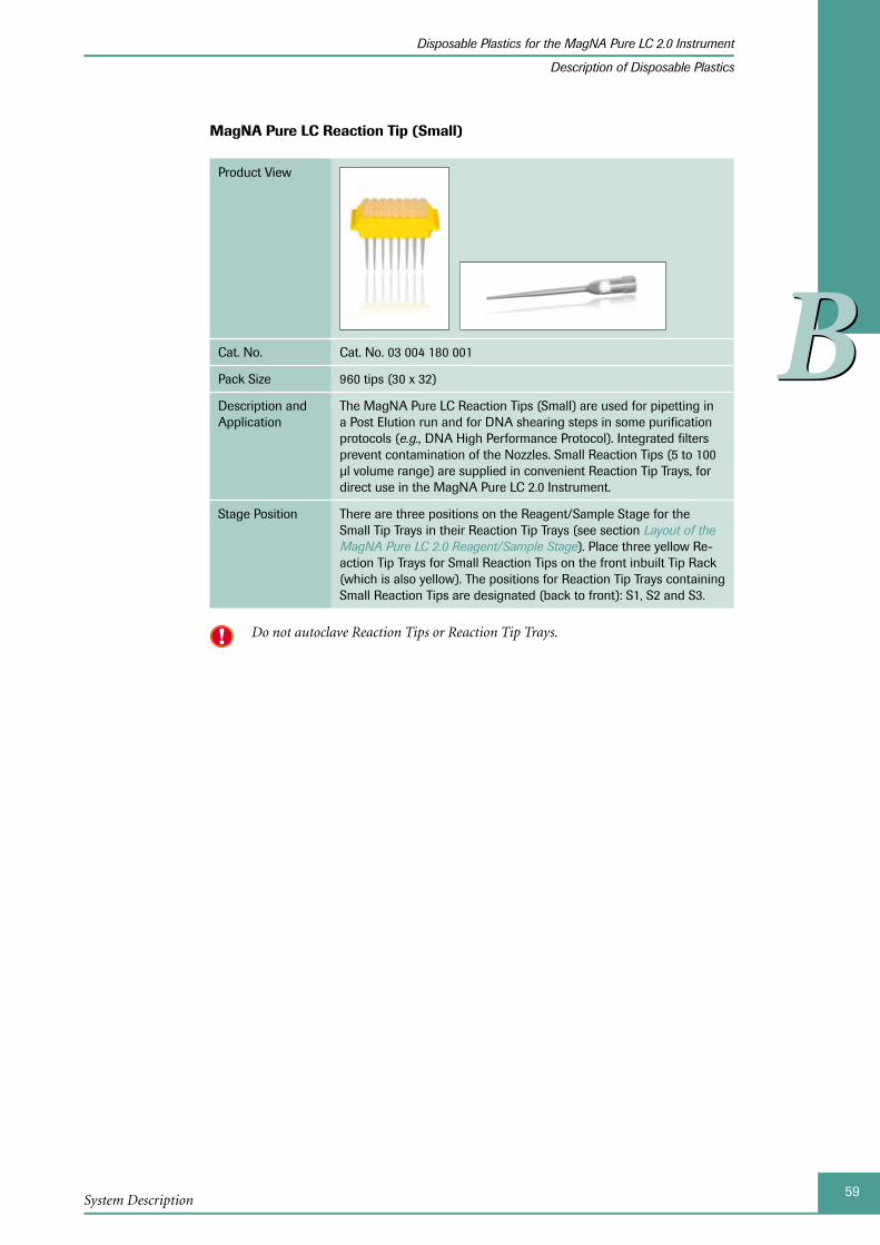
59System Description
Disposable Plastics for the MagNA Pure LC 2.0 Instrument
Description of Disposable Plastics
BB
MagNA Pure LC Reaction Tip (Small)
Product View
Cat. No. Cat. No. 03 004 180 001
Pack Size 960 tips (30 x 32)
Description and Application
The MagNA Pure LC Reaction Tips (Small) are used for pipetting in a Post Elution run and for DNA shearing steps in some purification protocols (e.g., DNA High Performance Protocol). Integrated filters prevent contamination of the Nozzles. Small Reaction Tips (5 to 100 µl volume range) are supplied in convenient Reaction Tip Trays, for direct use in the MagNA Pure LC 2.0 Instrument.
Stage Position There are three positions on the Reagent/Sample Stage for the Small Tip Trays in their Reaction Tip Trays (see section Layout of the MagNA Pure LC 2.0 Reagent/Sample Stage). Place three yellow Re-action Tip Trays for Small Reaction Tips on the front inbuilt Tip Rack (which is also yellow). The positions for Reaction Tip Trays containing Small Reaction Tips are designated (back to front): S1, S2 and S3.
Do not autoclave Reaction Tips or Reaction Tip Trays.
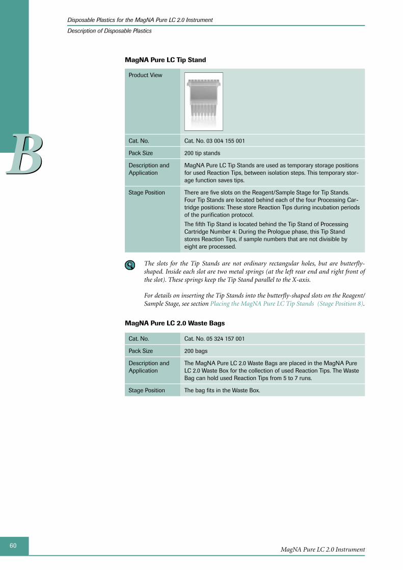
60MagNA Pure LC 2.0 Instrument
Disposable Plastics for the MagNA Pure LC 2.0 Instrument
Description of Disposable Plastics
BB
MagNA Pure LC Tip Stand
Product View
Cat. No. Cat. No. 03 004 155 001
Pack Size 200 tip stands
Description and Application
MagNA Pure LC Tip Stands are used as temporary storage positions for used Reaction Tips, between isolation steps. This temporary stor-age function saves tips.
Stage Position There are five slots on the Reagent/Sample Stage for Tip Stands. Four Tip Stands are located behind each of the four Processing Car-tridge positions: These store Reaction Tips during incubation periods of the purification protocol.
The fifth Tip Stand is located behind the Tip Stand of Processing Cartridge Number 4: During the Prologue phase, this Tip Stand stores Reaction Tips, if sample numbers that are not divisible by eight are processed.
The slots for the Tip Stands are not ordinary rectangular holes, but are butterfly-shaped. Inside each slot are two metal springs (at the left rear end and right front of the slot). These springs keep the Tip Stand parallel to the X-axis.
For details on inserting the Tip Stands into the butterfly-shaped slots on the Reagent/Sample Stage, see section Placing the MagNA Pure LC Tip Stands (Stage Position 8).
MagNA Pure LC 2.0 Waste Bags
Cat. No. Cat. No. 05 324 157 001
Pack Size 200 bags
Description and Application
The MagNA Pure LC 2.0 Waste Bags are placed in the MagNA Pure LC 2.0 Waste Box for the collection of used Reaction Tips. The Waste Bag can hold used Reaction Tips from 5 to 7 runs.
Stage Position The bag fits in the Waste Box.
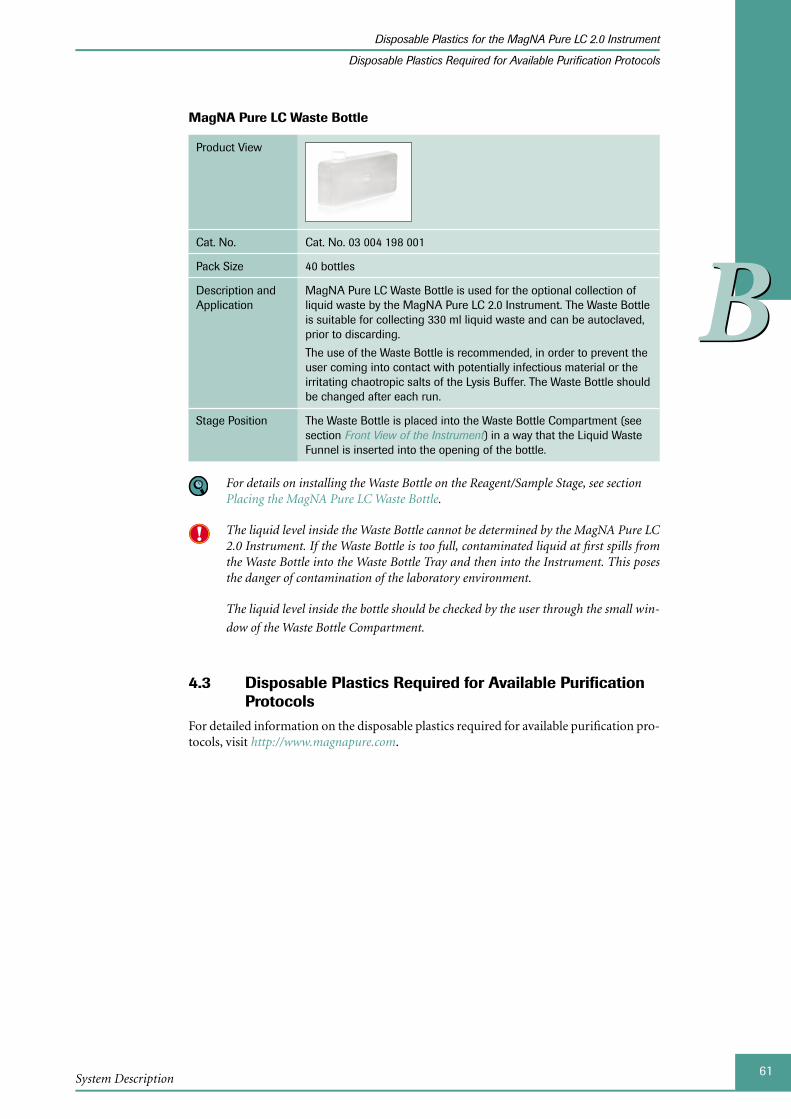
61System Description
Disposable Plastics for the MagNA Pure LC 2.0 Instrument
Disposable Plastics Required for Available Purification Protocols
BB
MagNA Pure LC Waste Bottle
Product View
Cat. No. Cat. No. 03 004 198 001
Pack Size 40 bottles
Description and Application
MagNA Pure LC Waste Bottle is used for the optional collection of liquid waste by the MagNA Pure LC 2.0 Instrument. The Waste Bottle is suitable for collecting 330 ml liquid waste and can be autoclaved, prior to discarding.
The use of the Waste Bottle is recommended, in order to prevent the user coming into contact with potentially infectious material or the irritating chaotropic salts of the Lysis Buffer. The Waste Bottle should be changed after each run.
Stage Position The Waste Bottle is placed into the Waste Bottle Compartment (see section Front View of the Instrument) in a way that the Liquid Waste Funnel is inserted into the opening of the bottle.
For details on installing the Waste Bottle on the Reagent/Sample Stage, see section Placing the MagNA Pure LC Waste Bottle.
The liquid level inside the Waste Bottle cannot be determined by the MagNA Pure LC 2.0 Instrument. If the Waste Bottle is too full, contaminated liquid at first spills from the Waste Bottle into the Waste Bottle Tray and then into the Instrument. This poses the danger of contamination of the laboratory environment.
The liquid level inside the bottle should be checked by the user through the small win-
dow of the Waste Bottle Compartment.
4.3 Disposable Plastics Required for Available Purification Protocols
For detailed information on the disposable plastics required for available purification pro-tocols, visit http://www.magnapure.com.

62MagNA Pure LC 2.0 Instrument
BB
Chapter C • Operation
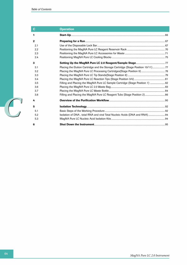
64MagNA Pure LC 2.0 Instrument
Table of Contents
CC
C Operation
1 Start-Up ...............................................................................................................................................................66
2 Preparing for a Run ....................................................................................................................................... 67
2.1 Use of the Disposable Lock Bar ................................................................................................................... 672.2 Positioning the MagNA Pure LC Reagent Reservoir Rack ................................................................ 702.3 Positioning the MagNA Pure LC Accessories for Waste ....................................................................712.4 Positioning MagNA Pure LC Cooling Blocks .......................................................................................... 75
3 Setting Up the MagNA Pure LC 2.0 Reagent/Sample Stage ................................................. 77
3.1 Placing the Elution Cartridge and the Storage Cartridge (Stage Position 10/11) ..................... 773.2 Placing the MagNA Pure LC Processing Cartridges(Stage Position 9) ........................................ 783.3 Placing the MagNA Pure LC Tip Stands(Stage Position 8) ............................................................... 793.4 Placing the MagNA Pure LC Reaction Tips (Stage Position 3/4) ....................................................813.5 Filling and Placing the MagNA Pure LC Sample Cartridge (Stage Position 1) ......................... 823.6 Placing the MagNA Pure LC 2.0 Waste Bag ............................................................................................ 833.7 Placing the MagNA Pure LC Waste Bottle ...............................................................................................843.8 Filling and Placing the MagNA Pure LC Reagent Tubs (Stage Position 2) ..................................86
4 Overview of the Purification Workflow ...............................................................................................90
5 Isolation Technology..................................................................................................................................... 92
5.1 Basic Steps of the Working Procedure ...................................................................................................... 925.2 Isolation of DNA , total RNA and viral Total Nucleic Acids (DNA and RNA) ............................945.3 MagNA Pure LC Nucleic Acid Isolation Kits ...........................................................................................94
6 Shut Down the Instrument ........................................................................................................................ 95
65
CC
Operation
Operation
Prior to starting operation of the MagNA Pure LC 2.0 Instrument, review chapters System Description and MagNA Pure LC 2.0 Software, to verify the identification and location of the MagNA Pure LC 2.0 Instrument components and to become familiar with the MagNA Pure LC 2.0 Software.
This chapter describes how to
Start-up the MagNA Pure LC 2.0 Instrument ►
Prepare a run ►
Place the disposable plastics on the Reagent/Sample Stage ►
Isolate DNA, RNA and viral total nucleic acid (DNA and RNA) ►
Shut down the MagNA Pure LC 2.0 Instrument ►
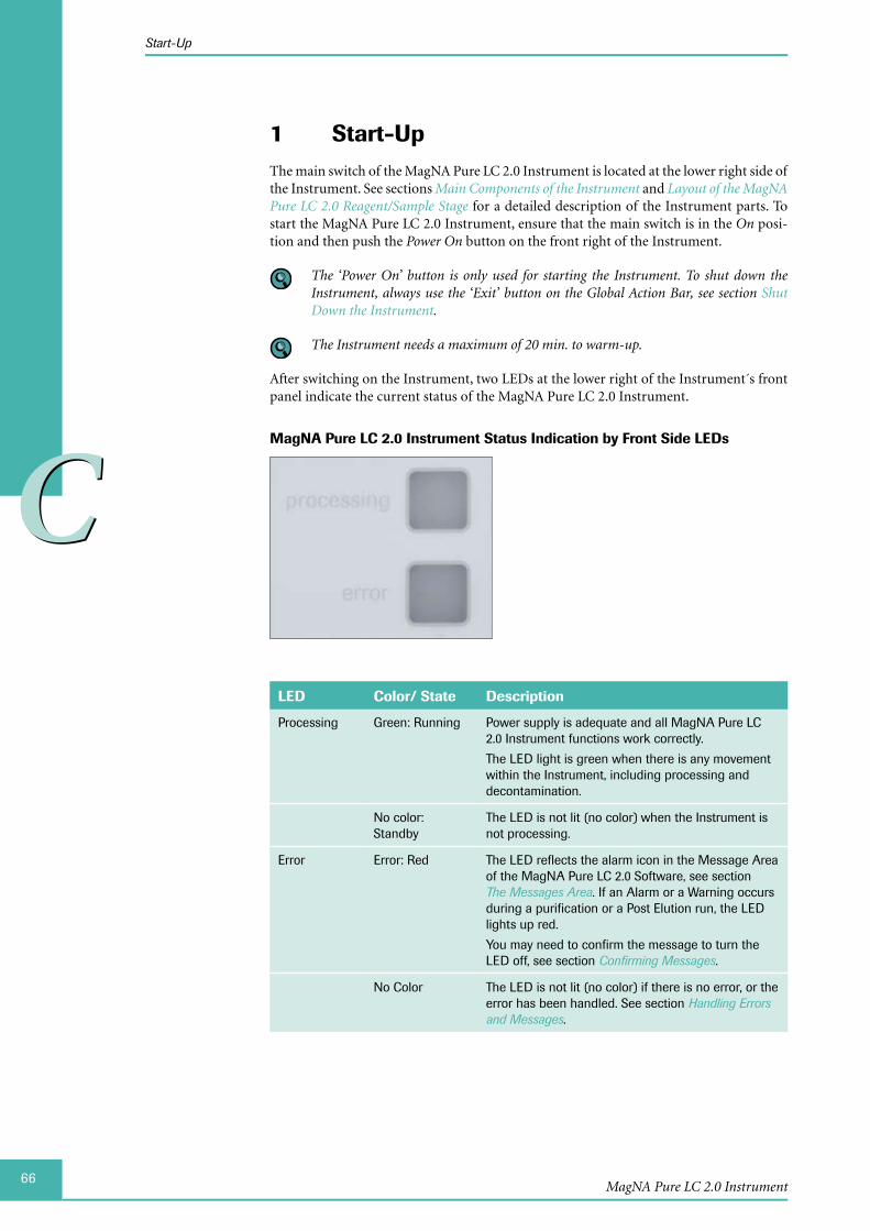
66
CC
MagNA Pure LC 2.0 Instrument
Start-Up
Start-Up1 The main switch of the MagNA Pure LC 2.0 Instrument is located at the lower right side of the Instrument. See sections Main Components of the Instrument and Layout of the MagNA Pure LC 2.0 Reagent/Sample Stage for a detailed description of the Instrument parts. To start the MagNA Pure LC 2.0 Instrument, ensure that the main switch is in the On posi-tion and then push the Power On button on the front right of the Instrument.
The ‘Power On’ button is only used for starting the Instrument. To shut down the Instrument, always use the ‘Exit’ button on the Global Action Bar, see section Shut Down the Instrument.
The Instrument needs a maximum of 20 min. to warm-up.
After switching on the Instrument, two LEDs at the lower right of the Instrument´s front panel indicate the current status of the MagNA Pure LC 2.0 Instrument.
MagNA Pure LC 2.0 Instrument Status Indication by Front Side LEDs
LED Color/ State Description
Processing Green: Running Power supply is adequate and all MagNA Pure LC 2.0 Instrument functions work correctly.
The LED light is green when there is any movement within the Instrument, including processing and decontamination.
No color: Standby
The LED is not lit (no color) when the Instrument is not processing.
Error Error: Red The LED reflects the alarm icon in the Message Area of the MagNA Pure LC 2.0 Software, see section The Messages Area. If an Alarm or a Warning occurs during a purification or a Post Elution run, the LED lights up red.
You may need to confirm the message to turn the LED off, see section Confirming Messages.
No Color The LED is not lit (no color) if there is no error, or the error has been handled. See section Handling Errors and Messages.
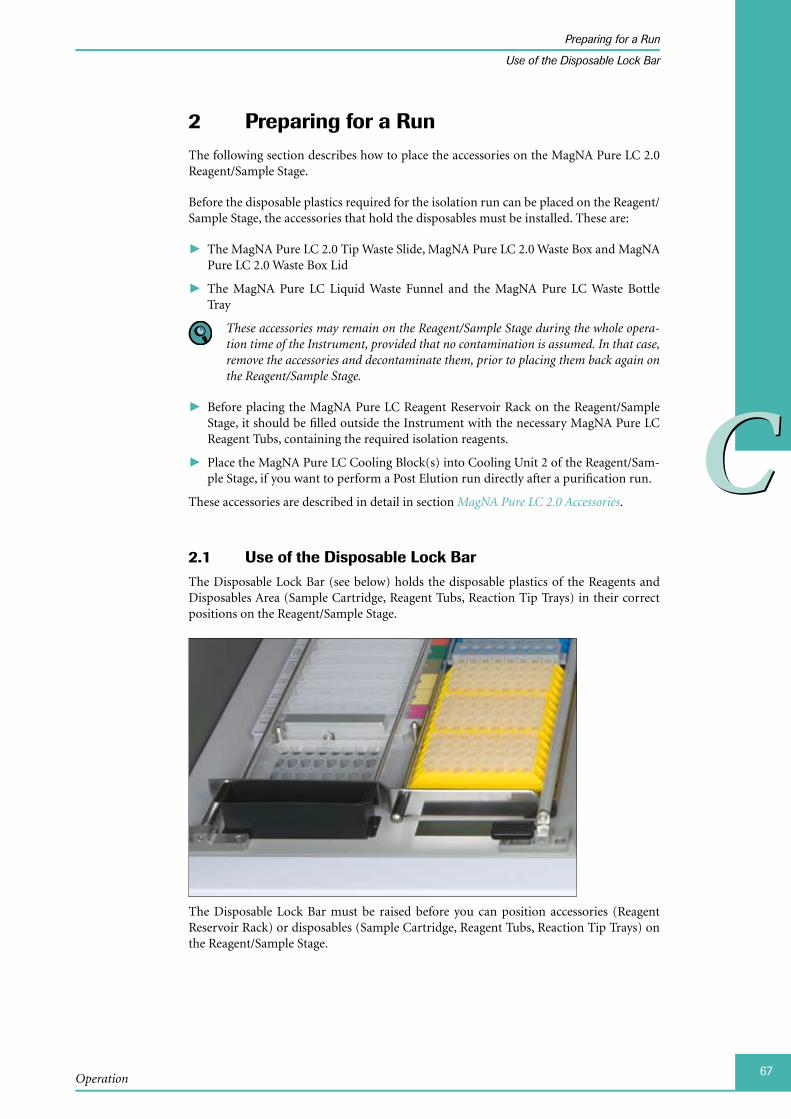
67
CC
Operation
Preparing for a Run
Use of the Disposable Lock Bar
Preparing for a Run2 The following section describes how to place the accessories on the MagNA Pure LC 2.0 Reagent/Sample Stage.
Before the disposable plastics required for the isolation run can be placed on the Reagent/Sample Stage, the accessories that hold the disposables must be installed. These are:
The MagNA Pure LC 2.0 Tip Waste Slide, MagNA Pure LC 2.0 Waste Box and MagNA ►Pure LC 2.0 Waste Box Lid
The MagNA Pure LC Liquid Waste Funnel and the MagNA Pure LC Waste Bottle ►Tray
These accessories may remain on the Reagent/Sample Stage during the whole opera-tion time of the Instrument, provided that no contamination is assumed. In that case, remove the accessories and decontaminate them, prior to placing them back again on the Reagent/Sample Stage.
Before placing the MagNA Pure LC Reagent Reservoir Rack on the Reagent/Sample ►Stage, it should be filled outside the Instrument with the necessary MagNA Pure LC Reagent Tubs, containing the required isolation reagents.
Place the MagNA Pure LC Cooling Block(s) into Cooling Unit 2 of the Reagent/Sam- ►ple Stage, if you want to perform a Post Elution run directly after a purification run.
These accessories are described in detail in section MagNA Pure LC 2.0 Accessories.
Use of the Disposable Lock Bar2.1 The Disposable Lock Bar (see below) holds the disposable plastics of the Reagents and Disposables Area (Sample Cartridge, Reagent Tubs, Reaction Tip Trays) in their correct positions on the Reagent/Sample Stage.
The Disposable Lock Bar must be raised before you can position accessories (Reagent Reservoir Rack) or disposables (Sample Cartridge, Reagent Tubs, Reaction Tip Trays) on the Reagent/Sample Stage.
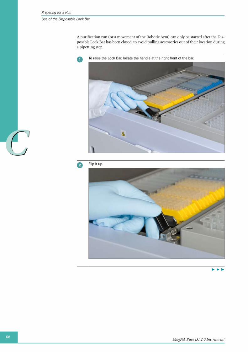
68
CC
MagNA Pure LC 2.0 Instrument
Preparing for a Run
Use of the Disposable Lock Bar
A purification run (or a movement of the Robotic Arm) can only be started after the Dis-posable Lock Bar has been closed, to avoid pulling accessories out of their location during a pipetting step.
To raise the Lock Bar, locate the handle at the right front of the bar.
Flip it up.
► ► ►
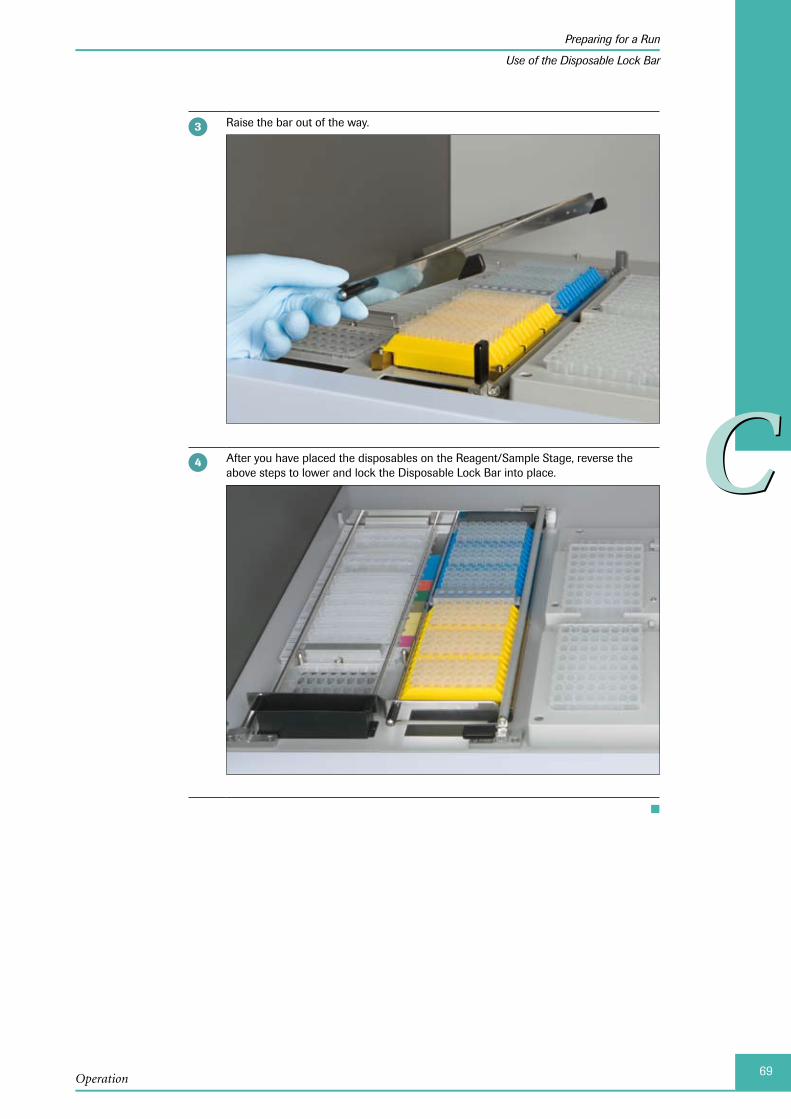
69
CC
Operation
Preparing for a Run
Use of the Disposable Lock Bar
Raise the bar out of the way.
After you have placed the disposables on the Reagent/Sample Stage, reverse the above steps to lower and lock the Disposable Lock Bar into place.
■
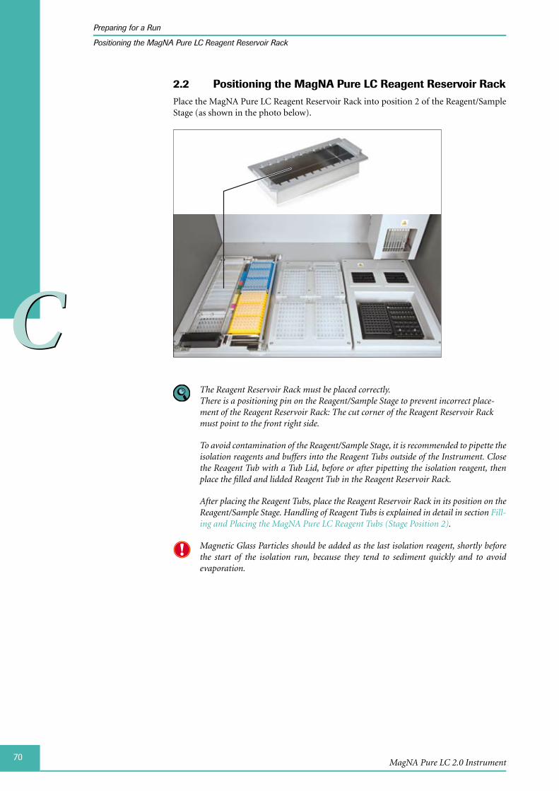
70
CC
MagNA Pure LC 2.0 Instrument
Preparing for a Run
Positioning the MagNA Pure LC Reagent Reservoir Rack
Positioning the MagNA Pure LC Reagent Reservoir Rack2.2 Place the MagNA Pure LC Reagent Reservoir Rack into position 2 of the Reagent/Sample Stage (as shown in the photo below).
The Reagent Reservoir Rack must be placed correctly. There is a positioning pin on the Reagent/Sample Stage to prevent incorrect place-ment of the Reagent Reservoir Rack: The cut corner of the Reagent Reservoir Rack must point to the front right side.
To avoid contamination of the Reagent/Sample Stage, it is recommended to pipette the isolation reagents and buffers into the Reagent Tubs outside of the Instrument. Close the Reagent Tub with a Tub Lid, before or after pipetting the isolation reagent, then place the filled and lidded Reagent Tub in the Reagent Reservoir Rack.
After placing the Reagent Tubs, place the Reagent Reservoir Rack in its position on the Reagent/Sample Stage. Handling of Reagent Tubs is explained in detail in section Fill-ing and Placing the MagNA Pure LC Reagent Tubs (Stage Position 2).
Magnetic Glass Particles should be added as the last isolation reagent, shortly before the start of the isolation run, because they tend to sediment quickly and to avoid evaporation.
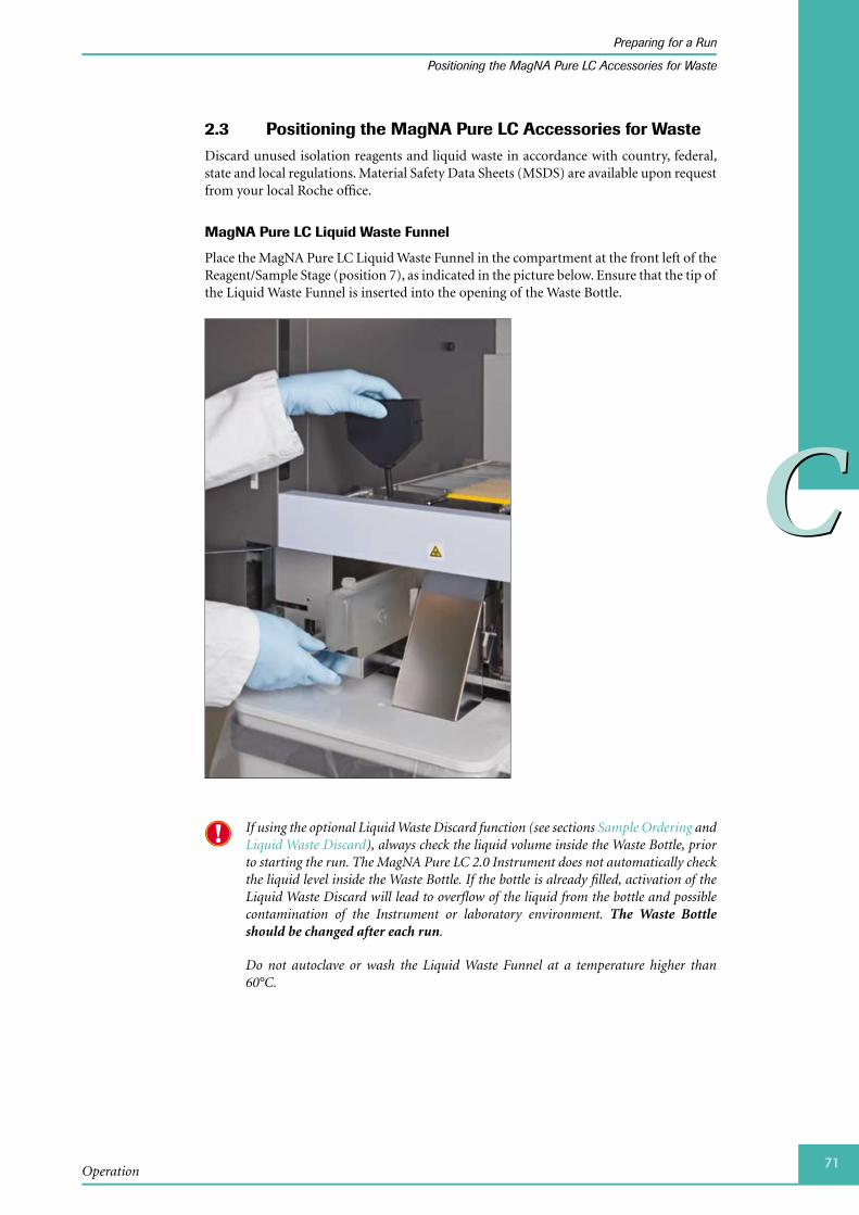
71
CC
Operation
Preparing for a Run
Positioning the MagNA Pure LC Accessories for Waste
Positioning the MagNA Pure LC Accessories2.3 for WasteDiscard unused isolation reagents and liquid waste in accordance with country, federal, state and local regulations. Material Safety Data Sheets (MSDS) are available upon request from your local Roche office.
MagNA Pure LC Liquid Waste Funnel
Place the MagNA Pure LC Liquid Waste Funnel in the compartment at the front left of the Reagent/Sample Stage (position 7), as indicated in the picture below. Ensure that the tip of the Liquid Waste Funnel is inserted into the opening of the Waste Bottle.
If using the optional Liquid Waste Discard function (see sections Sample Ordering and Liquid Waste Discard), always check the liquid volume inside the Waste Bottle, prior to starting the run. The MagNA Pure LC 2.0 Instrument does not automatically check the liquid level inside the Waste Bottle. If the bottle is already filled, activation of the Liquid Waste Discard will lead to overflow of the liquid from the bottle and possible contamination of the Instrument or laboratory environment. The Waste Bottle should be changed after each run.
Do not autoclave or wash the Liquid Waste Funnel at a temperature higher than 60°C.
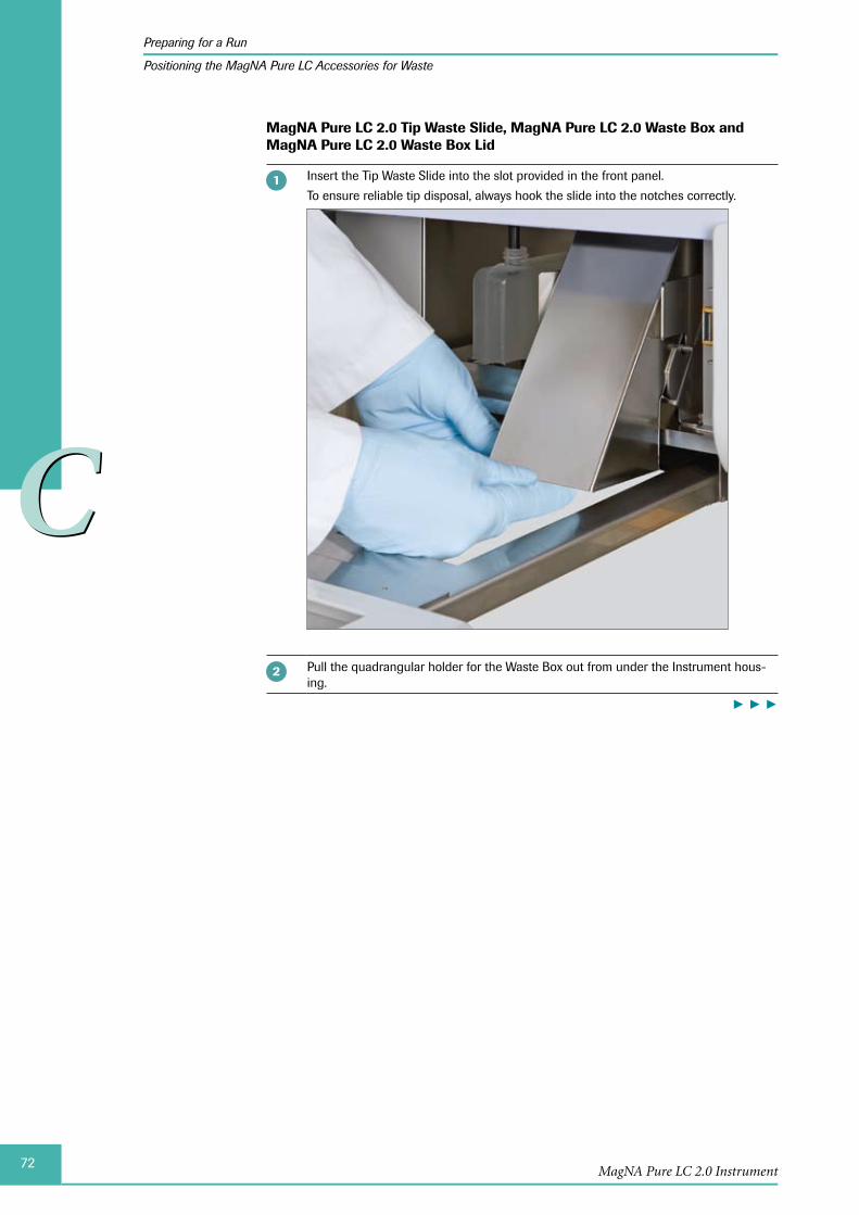
72
CC
MagNA Pure LC 2.0 Instrument
Preparing for a Run
Positioning the MagNA Pure LC Accessories for Waste
MagNA Pure LC 2.0 Tip Waste Slide, MagNA Pure LC 2.0 Waste Box and MagNA Pure LC 2.0 Waste Box Lid
Insert the Tip Waste Slide into the slot provided in the front panel.
To ensure reliable tip disposal, always hook the slide into the notches correctly.
Pull the quadrangular holder for the Waste Box out from under the Instrument hous-ing.
► ► ►
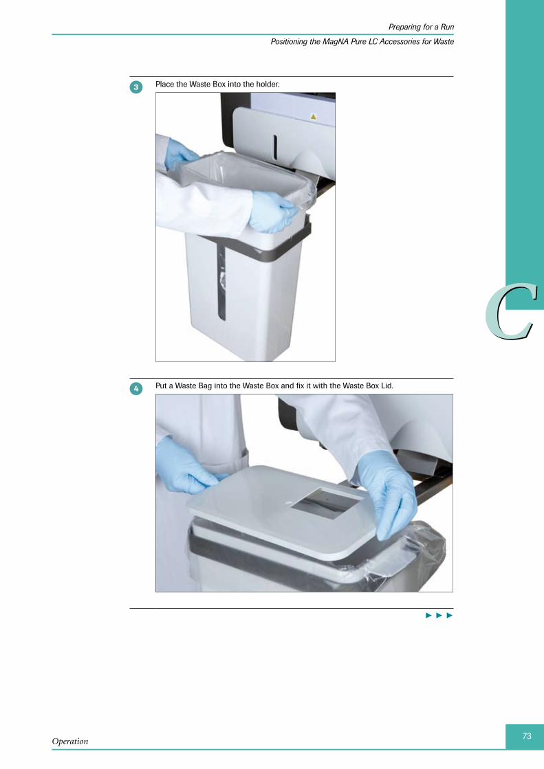
73
CC
Operation
Preparing for a Run
Positioning the MagNA Pure LC Accessories for Waste
Place the Waste Box into the holder.
Put a Waste Bag into the Waste Box and fix it with the Waste Box Lid.
► ► ►
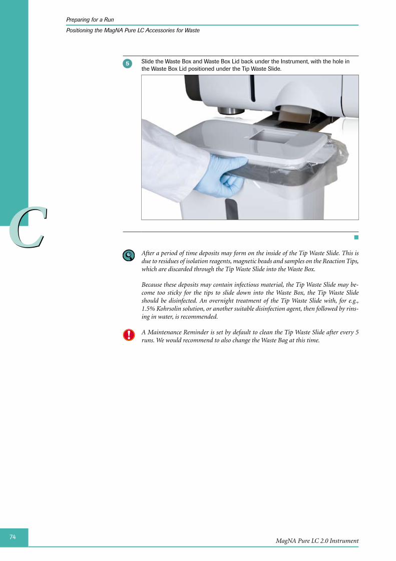
74
CC
MagNA Pure LC 2.0 Instrument
Preparing for a Run
Positioning the MagNA Pure LC Accessories for Waste
Slide the Waste Box and Waste Box Lid back under the Instrument, with the hole in the Waste Box Lid positioned under the Tip Waste Slide.
■
After a period of time deposits may form on the inside of the Tip Waste Slide. This is due to residues of isolation reagents, magnetic beads and samples on the Reaction Tips, which are discarded through the Tip Waste Slide into the Waste Box.
Because these deposits may contain infectious material, the Tip Waste Slide may be-come too sticky for the tips to slide down into the Waste Box, the Tip Waste Slide should be disinfected. An overnight treatment of the Tip Waste Slide with, for e.g., 1.5% Kohrsolin solution, or another suitable disinfection agent, then followed by rins-ing in water, is recommended.
A Maintenance Reminder is set by default to clean the Tip Waste Slide after every 5 runs. We would recommend to also change the Waste Bag at this time.
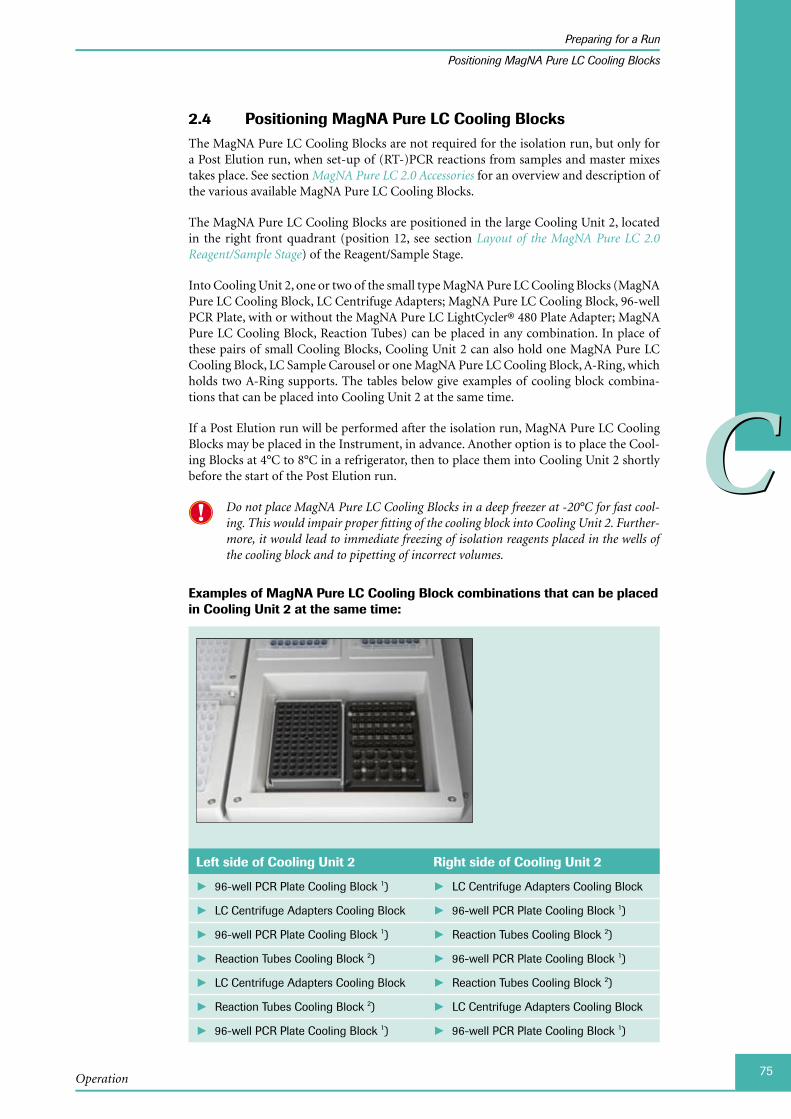
75
CC
Operation
Preparing for a Run
Positioning MagNA Pure LC Cooling Blocks
Positioning MagNA Pure LC Cooling Blocks2.4 The MagNA Pure LC Cooling Blocks are not required for the isolation run, but only for a Post Elution run, when set-up of (RT-)PCR reactions from samples and master mixes takes place. See section MagNA Pure LC 2.0 Accessories for an overview and description of the various available MagNA Pure LC Cooling Blocks.
The MagNA Pure LC Cooling Blocks are positioned in the large Cooling Unit 2, located in the right front quadrant (position 12, see section Layout of the MagNA Pure LC 2.0 Reagent/Sample Stage) of the Reagent/Sample Stage.
Into Cooling Unit 2, one or two of the small type MagNA Pure LC Cooling Blocks (MagNA Pure LC Cooling Block, LC Centrifuge Adapters; MagNA Pure LC Cooling Block, 96-well PCR Plate, with or without the MagNA Pure LC LightCycler® 480 Plate Adapter; MagNA Pure LC Cooling Block, Reaction Tubes) can be placed in any combination. In place of these pairs of small Cooling Blocks, Cooling Unit 2 can also hold one MagNA Pure LC Cooling Block, LC Sample Carousel or one MagNA Pure LC Cooling Block, A-Ring, which holds two A-Ring supports. The tables below give examples of cooling block combina-tions that can be placed into Cooling Unit 2 at the same time.
If a Post Elution run will be performed after the isolation run, MagNA Pure LC Cooling Blocks may be placed in the Instrument, in advance. Another option is to place the Cool-ing Blocks at 4°C to 8°C in a refrigerator, then to place them into Cooling Unit 2 shortly before the start of the Post Elution run.
Do not place MagNA Pure LC Cooling Blocks in a deep freezer at -20°C for fast cool-ing. This would impair proper fitting of the cooling block into Cooling Unit 2. Further-more, it would lead to immediate freezing of isolation reagents placed in the wells of the cooling block and to pipetting of incorrect volumes.
Examples of MagNA Pure LC Cooling Block combinations that can be placed in Cooling Unit 2 at the same time:
Left side of Cooling Unit 2 Right side of Cooling Unit 2
96-well PCR Plate Cooling Block ► 1) LC Centrifuge Adapters Cooling Block ►
LC Centrifuge Adapters Cooling Block ► 96-well PCR Plate Cooling Block ► 1)
96-well PCR Plate Cooling Block ► 1) Reaction Tubes Cooling Block ► 2)
Reaction Tubes Cooling Block ► 2) 96-well PCR Plate Cooling Block ► 1)
LC Centrifuge Adapters Cooling Block ► Reaction Tubes Cooling Block ► 2)
Reaction Tubes Cooling Block ► 2) LC Centrifuge Adapters Cooling Block ►
96-well PCR Plate Cooling Block ► 1) 96-well PCR Plate Cooling Block ► 1)

76
CC
MagNA Pure LC 2.0 Instrument
Preparing for a Run
Positioning MagNA Pure LC Cooling Blocks
Left side of Cooling Unit 2 Right side of Cooling Unit 2
LC Centrifuge Adapters Cooling Block ► LC Centrifuge Adapters Cooling Block ►
Reaction Tubes Cooling Block ► 2) Reaction Tubes Cooling Block ► 2)
Entire Cooling Unit 2
LC Sample Carousel Cooling Block (20 µl or 100 µl) ► 2)
A-Ring Cooling Block ► 2)
To position the LC Sample Carousel correctly into the cooling block, ensure that the pin of the cooling block fits correctly into the hole in the LC Sample Carousel.
Press firmly to ensure that the LC Sample Carousel is seated correctly!
1) The 96-well PCR Plate Cooling Block can accept LightCycler® 480 Multiwell Plates 96 with the LC 480 Plate Adapter, as well as, Type I or Type II PCR Plates, as listed in section 96-well PCR Plates.
2) The MagNA Pure LC Cooling Block, Reaction Tubes, the MagNA Pure LC Cooling Block, LC Sample Carousel and the MagNA Pure LC Cooling Block, A-Ring, are not included in the Instrument package, but can be ordered separately. Please refer to the table in section Additional MagNA Pure LC Cooling Blocks, or see section Ordering Information.
Before starting a run it is recommended to check the decontamination of the Instru-ment and the Liquid Drop Catcher disposable. For details, see chapter Maintenance.
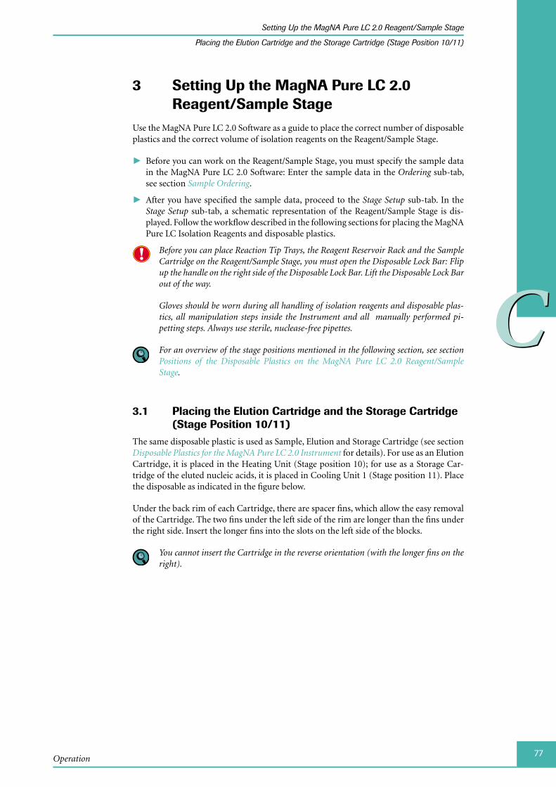
77
CC
Operation
Setting Up the MagNA Pure LC 2.0 Reagent/Sample Stage
Placing the Elution Cartridge and the Storage Cartridge (Stage Position 10/11)
3 Setting Up the MagNA Pure LC 2.0 Reagent/Sample Stage
Use the MagNA Pure LC 2.0 Software as a guide to place the correct number of disposable plastics and the correct volume of isolation reagents on the Reagent/Sample Stage.
Before you can work on the Reagent/Sample Stage, you must specify the sample data ►in the MagNA Pure LC 2.0 Software: Enter the sample data in the Ordering sub-tab, see section Sample Ordering.
After you have specified the sample data, proceed to the ► Stage Setup sub-tab. In the Stage Setup sub-tab, a schematic representation of the Reagent/Sample Stage is dis-played. Follow the workflow described in the following sections for placing the MagNA Pure LC Isolation Reagents and disposable plastics.
Before you can place Reaction Tip Trays, the Reagent Reservoir Rack and the Sample Cartridge on the Reagent/Sample Stage, you must open the Disposable Lock Bar: Flip up the handle on the right side of the Disposable Lock Bar. Lift the Disposable Lock Bar out of the way.
Gloves should be worn during all handling of isolation reagents and disposable plas-tics, all manipulation steps inside the Instrument and all manually performed pi-petting steps. Always use sterile, nuclease-free pipettes.
For an overview of the stage positions mentioned in the following section, see section Positions of the Disposable Plastics on the MagNA Pure LC 2.0 Reagent/Sample Stage.
Placing 3.1 the Elution Cartridge and the Storage Cartridge (Stage Position 10/11)
The same disposable plastic is used as Sample, Elution and Storage Cartridge (see section Disposable Plastics for the MagNA Pure LC 2.0 Instrument for details). For use as an Elution Cartridge, it is placed in the Heating Unit (Stage position 10); for use as a Storage Car-tridge of the eluted nucleic acids, it is placed in Cooling Unit 1 (Stage position 11). Place the disposable as indicated in the figure below.
Under the back rim of each Cartridge, there are spacer fins, which allow the easy removal of the Cartridge. The two fins under the left side of the rim are longer than the fins under the right side. Insert the longer fins into the slots on the left side of the blocks.
You cannot insert the Cartridge in the reverse orientation (with the longer fins on the right).
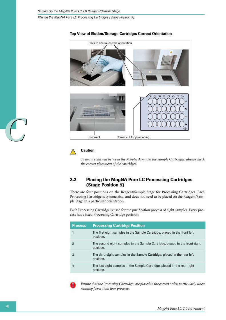
78
CC
MagNA Pure LC 2.0 Instrument
Setting Up the MagNA Pure LC 2.0 Reagent/Sample Stage
Placing the MagNA Pure LC Processing Cartridges (Stage Position 9)
Top View of Elution/Storage Cartridge: Correct Orientation
ABCDEFGH
14
32
Slots to ensure correct orientation
Corner cut for positioningIncorrect
Caution
To avoid collisions between the Robotic Arm and the Sample Cartridges, always check the correct placement of the cartridges.
Placing the MagNA Pure LC Processing Cartridges 3.2 (Stage Position 9)
There are four positions on the Reagent/Sample Stage for Processing Cartridges. Each Processing Cartridge is symmetrical and does not need to be placed on the Reagent/Sam-ple Stage in a particular orientation.
Each Processing Cartridge is used for the purification process of eight samples. Every pro-cess has a fixed Processing Cartridge position:
Process Processing Cartridge Position
1 The first eight samples in the Sample Cartridge, placed in the front left position.
2 The second eight samples in the Sample Cartridge, placed in the front right position.
3 The third eight samples in the Sample Cartridge, placed in the rear left position.
4 The last eight samples in the Sample Cartridge, placed in the rear right position.
Ensure that the Processing Cartridges are placed in the correct order, particularly when running fewer than four processes.

79
CC
Operation
Setting Up the MagNA Pure LC 2.0 Reagent/Sample Stage
Placing the MagNA Pure LC Tip Stands (Stage Position 8)
Placing the MagNA Pure LC 3.3 Tip Stands (Stage Position 8)
There are five slots on the Reagent/Sample Stage for Tip Stands.
The Tip Stands are used to store used Reaction Tips temporarily.
Four Tip Stands are located behind the Processing Cartridges. These Tip Stands store ►Reaction Tips that are used during the purification process.
One Tip Stand is located separately at the rear behind the Tip Stand of the Processing ►Cartridge Number 4. During the Prologue phase, this Tip Stand stores Reaction Tips, if sample numbers not divisible by eight are processed.
The slots for the Tip Stands are butterfly-shaped. Inside each slot, there are two metal springs, which keep the Tip Stand parallel to the X-axis. The right upper and left lower corners of the Tip Stand insert into hooks at the corner of the respective slot. When the Reaction Tips are inserted into their Tip Stand, these hooks prevent the Tip Stand from lifting with the Reaction Tips when the Nozzle Head picks up the parked Reaction Tips.

80
CC
MagNA Pure LC 2.0 Instrument
Setting Up the MagNA Pure LC 2.0 Reagent/Sample Stage
Placing the MagNA Pure LC Tip Stands (Stage Position 8)
To place the Tip Stands:
Insert a Tip Stand into the respective slot on the Reagent/Sample Stage.
Keep pushing down on the Tip Stand, while turning the Tip Stand clockwise, until the Tip Stand touches the top surface of the Reagent/Sample Stage.
The Tip Stand spontaneously turns parallel to the X-axis.
Ensure that the Tip Stands are inserted correctly into the hooks.
■
To remove the Tip Stand, turn the Tip Stand counterclockwise and pull it up.
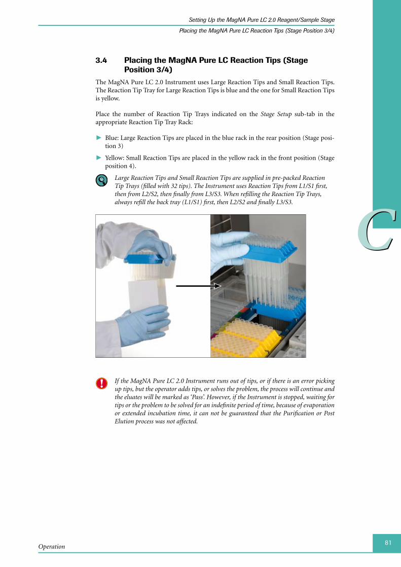
81
CC
Operation
Setting Up the MagNA Pure LC 2.0 Reagent/Sample Stage
Placing the MagNA Pure LC Reaction Tips (Stage Position 3/4)
Placing the 3.4 MagNA Pure LC Reaction Tips (Stage Position 3/4)
The MagNA Pure LC 2.0 Instrument uses Large Reaction Tips and Small Reaction Tips. The Reaction Tip Tray for Large Reaction Tips is blue and the one for Small Reaction Tips is yellow.
Place the number of Reaction Tip Trays indicated on the Stage Setup sub-tab in the appropriate Reaction Tip Tray Rack:
Blue: Large Reaction Tips are placed in the blue rack in the rear position (Stage posi- ►tion 3)
Yellow: Small Reaction Tips are placed in the yellow rack in the front position (Stage ►position 4).
Large Reaction Tips and Small Reaction Tips are supplied in pre-packed Reaction Tip Trays (filled with 32 tips). The Instrument uses Reaction Tips from L1/S1 first, then from L2/S2, then finally from L3/S3. When refilling the Reaction Tip Trays, always refill the back tray (L1/S1) first, then L2/S2 and finally L3/S3.
If the MagNA Pure LC 2.0 Instrument runs out of tips, or if there is an error picking up tips, but the operator adds tips, or solves the problem, the process will continue and the eluates will be marked as ‘Pass’. However, if the Instrument is stopped, waiting for tips or the problem to be solved for an indefinite period of time, because of evaporation or extended incubation time, it can not be guaranteed that the Purification or Post Elution process was not affected.
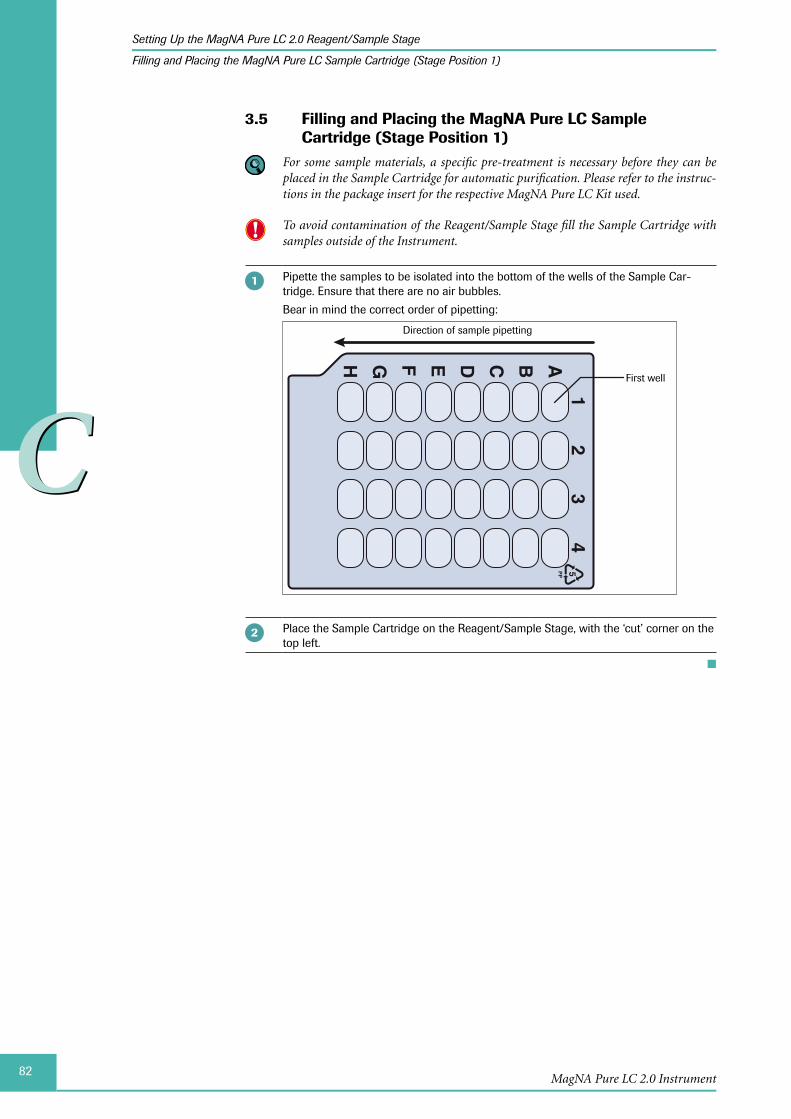
82
CC
MagNA Pure LC 2.0 Instrument
Setting Up the MagNA Pure LC 2.0 Reagent/Sample Stage
Filling and Placing the MagNA Pure LC Sample Cartridge (Stage Position 1)
Filling and Placing the 3.5 MagNA Pure LC Sample Cartridge (Stage Position 1)
For some sample materials, a specific pre-treatment is necessary before they can be placed in the Sample Cartridge for automatic purification. Please refer to the instruc-tions in the package insert for the respective MagNA Pure LC Kit used.
To avoid contamination of the Reagent/Sample Stage fill the Sample Cartridge with samples outside of the Instrument.
Pipette the samples to be isolated into the bottom of the wells of the Sample Car-tridge. Ensure that there are no air bubbles.
Bear in mind the correct order of pipetting:
ABCDEFGH
14
32
Direction of sample pipetting
First well
Place the Sample Cartridge on the Reagent/Sample Stage, with the ‘cut’ corner on the top left.
■

83
CC
Operation
Setting Up the MagNA Pure LC 2.0 Reagent/Sample Stage
Placing the MagNA Pure LC 2.0 Waste Bag
Placing the 3.6 MagNA Pure LC 2.0 Waste BagWhen the Instrument has finished using a set of Reaction Tips, it automatically discards them through the Tip Waste Slide into the Waste Bag secured within the Waste Box (see sections Disposable Plastics for the MagNA Pure LC 2.0 Instrument and Positioning the MagNA Pure LC Accessories for Waste for details).
To place the Waste Bag into the Waste Box:
Pull the Waste Box drawer all the way out from under the Instrument. Remove the Waste Box Lid from the Waste Box.
Insert the Waste Bag into the Waste Box.
► ► ►
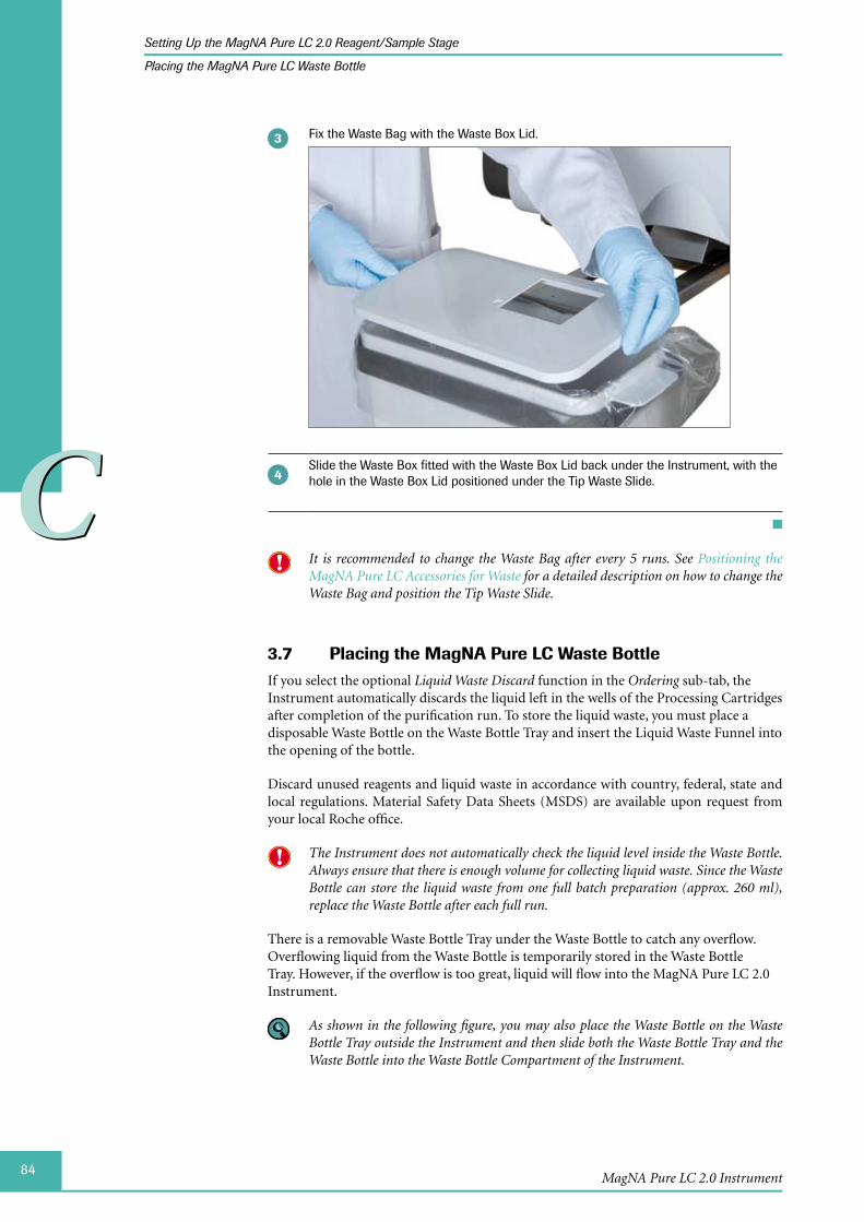
84
CC
MagNA Pure LC 2.0 Instrument
Setting Up the MagNA Pure LC 2.0 Reagent/Sample Stage
Placing the MagNA Pure LC Waste Bottle
Fix the Waste Bag with the Waste Box Lid.
Slide the Waste Box fitted with the Waste Box Lid back under the Instrument, with the hole in the Waste Box Lid positioned under the Tip Waste Slide.
■
It is recommended to change the Waste Bag after every 5 runs. See Positioning the MagNA Pure LC Accessories for Waste for a detailed description on how to change the Waste Bag and position the Tip Waste Slide.
Placing the MagNA Pure LC 3.7 Waste BottleIf you select the optional Liquid Waste Discard function in the Ordering sub-tab, the Instrument automatically discards the liquid left in the wells of the Processing Cartridges after completion of the purification run. To store the liquid waste, you must place a disposable Waste Bottle on the Waste Bottle Tray and insert the Liquid Waste Funnel into the opening of the bottle.
Discard unused reagents and liquid waste in accordance with country, federal, state and local regulations. Material Safety Data Sheets (MSDS) are available upon request from your local Roche office.
The Instrument does not automatically check the liquid level inside the Waste Bottle. Always ensure that there is enough volume for collecting liquid waste. Since the Waste Bottle can store the liquid waste from one full batch preparation (approx. 260 ml), replace the Waste Bottle after each full run.
There is a removable Waste Bottle Tray under the Waste Bottle to catch any overflow. Overflowing liquid from the Waste Bottle is temporarily stored in the Waste Bottle Tray. However, if the overflow is too great, liquid will flow into the MagNA Pure LC 2.0 Instrument.
As shown in the following figure, you may also place the Waste Bottle on the Waste Bottle Tray outside the Instrument and then slide both the Waste Bottle Tray and the Waste Bottle into the Waste Bottle Compartment of the Instrument.

85
CC
Operation
Setting Up the MagNA Pure LC 2.0 Reagent/Sample Stage
Placing the MagNA Pure LC Waste Bottle
To place the Liquid Waste Bottle:
Pull the Waste Bottle Tray all the way out and place the Waste Bottle on it.
Lift the Liquid Waste Funnel and slide the Waste Bottle Tray back into the Instrument.
► ► ►
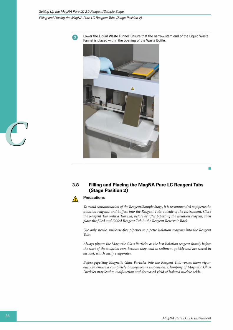
86
CC
MagNA Pure LC 2.0 Instrument
Setting Up the MagNA Pure LC 2.0 Reagent/Sample Stage
Filling and Placing the MagNA Pure LC Reagent Tubs (Stage Position 2)
Lower the Liquid Waste Funnel. Ensure that the narrow stem end of the Liquid Waste Funnel is placed within the opening of the Waste Bottle.
■
Filling and Placing the 3.8 MagNA Pure LC Reagent Tubs (Stage Position 2)
Precautions
To avoid contamination of the Reagent/Sample Stage, it is recommended to pipette the isolation reagents and buffers into the Reagent Tubs outside of the Instrument. Close the Reagent Tub with a Tub Lid, before or after pipetting the isolation reagent, then place the filled and lidded Reagent Tub in the Reagent Reservoir Rack.
Use only sterile, nuclease-free pipettes to pipette isolation reagents into the Reagent Tubs.
Always pipette the Magnetic Glass Particles as the last isolation reagent shortly before the start of the isolation run, because they tend to sediment quickly and are stored in alcohol, which easily evaporates.
Before pipetting Magnetic Glass Particles into the Reagent Tub, vortex them vigor-ously to ensure a completely homogeneous suspension. Clumping of Magnetic Glass Particles may lead to malfunction and decreased yield of isolated nucleic acids.
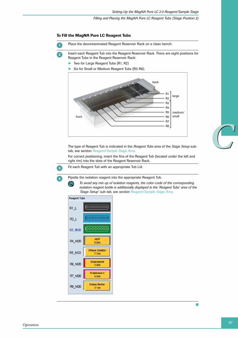
87
CC
Operation
Setting Up the MagNA Pure LC 2.0 Reagent/Sample Stage
Filling and Placing the MagNA Pure LC Reagent Tubs (Stage Position 2)
To Fill the MagNA Pure LC Reagent Tubs
Place the decontaminated Reagent Reservoir Rack on a clean bench.
Insert each Reagent Tub into the Reagent Reservoir Rack. There are eight positions for Reagent Tubs in the Reagent Reservoir Rack:
Two for Large Reagent Tubs (R1, R2) ►Six for Small or Medium Reagent Tubs (R3-R8). ►
R1
R8R7R6R5R4R3R2
large
medium/small
back
front
The type of Reagent Tub is indicated in the Reagent Tubs area of the Stage Setup sub-tab, see section Reagent/Sample Stage Area.
For correct positioning, insert the fins of the Reagent Tub (located under the left and right rim) into the slots of the Reagent Reservoir Rack.
Fit each Reagent Tub with an appropriate Tub Lid.
Pipette the isolation reagent into the appropriate Reagent Tub.
To avoid any mix up of isolation reagents, the color-code of the corresponding isolation reagent bottle is additionally displayed in the ‘Reagent Tubs’ area of the ‘Stage Setup’ sub-tab, see section Reagent/Sample Stage Area.
■
88
CC
MagNA Pure LC 2.0 Instrument
Setting Up the MagNA Pure LC 2.0 Reagent/Sample Stage
Filling and Placing the MagNA Pure LC Reagent Tubs (Stage Position 2)
Precautions
In the event that there is a delay in the start of a purification run, seal the Reagent Tubs with a Tub Lid Seal, to prevent evaporation of the isolation reagents.
Isolation reagents must be stored at room temperature to prevent crystallization, ex-cept the Proteinase K solution, which must be stored at 4°C.
Ensure that all isolation reagents are equilibrated to room temperature before starting the purification run and that the Tub Lid Seals are removed from the Reagent Tubs, prior to placing them on the Reagent/Sample Stage.
Magnetic Glass Particles should never be stored in the Reagent Tubs, because they sedi-ment and clump, as well, they are stored in alcohol, which easily evaporates.
Place the Reagent Reservoir Rack into Reagent/Sample Stage position 2, as described in detail in section Positioning the MagNA Pure LC Reagent Reservoir Rack.

89
CC
Operation
Setting Up the MagNA Pure LC 2.0 Reagent/Sample Stage
Filling and Placing the MagNA Pure LC Reagent Tubs (Stage Position 2)
To Place the MagNA Pure LC Rea gent Tubs and Isolation Reagents
Use MagNA Pure LC Positioning Frames to place the Reagent Tubs, as this makes it much easier. For every MagNA Pure LC Kit, a Positioning Frame for the Reagent Reservoir Rack is available. These Positioning Frames fit on the rim of the Reagent Reservoir Rack.
The Positioning Frames show the correct order of isolation reagents in the Reagent Res-ervoir Rack, for the respective MagNA Pure LC Kit. The name of the isolation reagent is printed on the left border of the frame. The color-code of the isolation reagent bottle/vial from the MagNA Pure LC Kit is printed on the right border of the frame.
As an example the Positioning Frame for the MagNA Pure LC DNA Isolation Kit I is shown:
Name of the reagent kit
Ordering number
Lid color of thereagent vesselfrom the kit
Name of the reagentfor this tub position
Positioning Frames may be ordered separately, see the Ordering Information in the package insert of the respective MagNA Pure LC Kit.
90
CC
MagNA Pure LC 2.0 Instrument
Overview of the Purification Workflow
4 Overview of the Purification WorkflowThe MagNA Pure LC 2.0 Instrument automatically performs a nucleic acid purification, starting from biological research sample material, with a final end-product of highly puri-fied, isolated nucleic acid, ready for downstream applications such, as PCR.
The MagNA Pure LC 2.0 Instrument automatically performs all steps of the purification procedure with specially designed nuclease-free, disposable Reaction Tips. These Reaction Tips not only transfer the lysed sample material, but also serve as ‘reaction vials’ for the isolation procedure. Within the Reaction Tips, nucleic acids are bound to Magnetic Glass Particles (MGPs; see section Isolation Technology for details), washed free from debris and impurities and finally eluted from the MGPs in pure form. Eluted nucleic acids are then transferred into the wells of a Storage Cartridge, ready for further use or storage.
All isolation reagents required for the purification process are included in the MagNA Pure LC Kits. The isolation reagents are supplied for the purification process by pipetting them into Reagent Tubs, which are placed on the MagNA Pure LC 2.0 Reagent/Sample Stage.
Pre-programmed purification protocols, containing the instructions for all isolation steps are pre-installed together with the MagNA Pure LC 2.0 Software. The user selects an appropriate purification protocol depending on the type of sample material and the type of nucleic acid that is to be isolated.
The user then provides the software with details of the samples, places the required isolation reagents and plastic disposables on the Reagent/Sample Stage and finally starts and monitors the run.
See the following procedure for an overview of the main handling steps required for prep-aration and execution of a purification run:
System Set-up
Switch on the MagNA Pure LC 2.0 Instrument, see section ► Start-Up.
Login and start the MagNA Pure LC 2.0 Software, see section ► Starting the MagNA Pure LC 2.0 Software.
Check for necessary maintenance handling, see chapter Maintenance.
Place the Waste Bag and (optionally) the Waste Bottle. ► Place or change the Liquid Drop Catcher disposable. ►
Sample ordering, see section Maintenance.
Open the ► Workplace tab and access the Ordering sub-tab.
Specify sample data. ►Select the appropriate purification protocol and specify protocol data. ►Select the appropriate Post Elution protocol, if required and specify protocol data. ►
Stage Set-up, see section Stage Setup for a Purification Run.
Open the ► Stage Setup sub-tab of the Workplace tab.
Place samples into the Sample Cartridge on the Reagent/Sample Stage. ►Pipette the required isolation reagents into the appropriate Reagent Tubs and ►place them in the Reagent Reservoir Rack (outside the Instrument).
Place the filled Reagent Reservoir Rack and all other required disposable plas- ►tics on the Reagent/Sample Stage. MGPs should be pipetted as the last isolation reagent, just before the Purification Run starts.
► ► ►
91
CC
Operation
Overview of the Purification Workflow
Purification run
Start the purification run and monitor it on the ► Run Status window, see sections Starting and Stopping a Purification Run and Monitoring a Purification Run.
Evaluate the outcome of the purification run on the ► Batch Result sub-tab, see sec-tion Batch Results.
Post Elution run, see chapter Post Elution.
Open the ► Post Elution Edit (sub-)tab and create or open a Post Elution Protocol, see section The Post Elution Edit (Sub-)Tab and the subsequent sections.
For programming Post Elution steps you can use the Post Elution function of the MagNA Pure LC 2.0 System or the Post Elution Protocol Editor on an external PC. See chapter Post Elution for a detailed description.
Start a Post Elution run, see section ► To start a Post Elution run or a Post Elution simulation:.
► Perform automatic (RT-)PCR Set-up using the Post Elution function.
Evaluate the outcome of the Post Elution run on the ► Post Elution Results sub-tab, see section Post Elution Results.
■
After the purification and Post Elution run has finished, the results are saved in the database automatically. The results may include the following information: Sample number, type, name, comment and position and result value, status and flag.
Depending on your settings, the results are sent to a host automatically or you can upload the result data manually, see section Setting up Parameters.

92
CC
MagNA Pure LC 2.0 Instrument
Isolation Technology
Basic Steps of the Working Procedure
Isolation Technology5
Basic Steps of the 5.1 Working ProcedureFor the isolation of DNA, RNA and viral total nucleic acids (DNA and RNA), proprietary Magnetic Glass Particles and specialized MagNA Pure LC Kits are used. DNA and RNA bind to Magnetic Glass Particles (MGPs) in the presence of a chaotropic salt at a pH >7.0. MGPs have a glass (silica) surface and a magnetic core.
Nucleic acids are bound to the silica-surface of the MGPs in the presence of isopropanol and high concentrations of chaotropic salts, which remove water from hydrated mole-cules in solution. Polysaccharides and proteins do not bind to the beads and are removed by sequential washing steps. Pure nucleic acids are then eluted from the beads by applying low-salt conditions and heat.
Once bound to the surface of the MGPs, the nucleic acids can be separated from the solu-tion with a magnet. The advantage of the isolation technology that the MagNA Pure LC uses, is that it requires no centrifugation or any other manual steps.
For a description of the basic workflow of the Instrument during a purification run and of the detailed isolation steps for the various types of nucleic acids, see the following schematics below. Please note this is only an example and not the exact workflow for all protocols.
Workflow Description
Step 1 During the Prologue Phase, isolation reagents are transported from the Re-agent Tubs into the wells of the Processing Cartridge and Elution Cartridge.
Step 2 Samples are lysed in the wells of the Sample Cartridge. The lysates are then transferred to the Processing Cartridge.
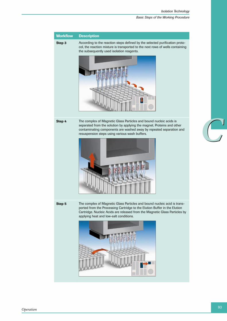
93
CC
Operation
Isolation Technology
Basic Steps of the Working Procedure
Workflow Description
Step 3 According to the reaction steps defined by the selected purification proto-col, the reaction mixture is transported to the next rows of wells containing the subsequently used isolation reagents.
Step 4 The complex of Magnetic Glass Particles and bound nucleic acids is separated from the solution by applying the magnet. Proteins and other contaminating components are washed away by repeated separation and resuspension steps using various wash buffers.
Step 5 The complex of Magnetic Glass Particles and bound nucleic acid is trans-ported from the Processing Cartridge to the Elution Buffer in the Elution Cartridge. Nucleic Acids are released from the Magnetic Glass Particles by applying heat and low-salt conditions.
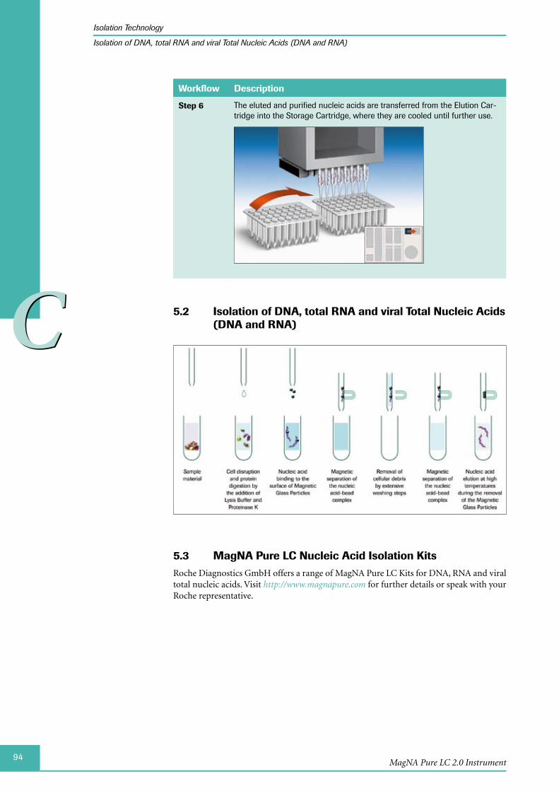
94
CC
MagNA Pure LC 2.0 Instrument
Isolation Technology
Isolation of DNA, total RNA and viral Total Nucleic Acids (DNA and RNA)
Workflow Description
Step 6 The eluted and purified nucleic acids are transferred from the Elution Car-tridge into the Storage Cartridge, where they are cooled until further use.
Isolation of DNA, total RNA and viral Total Nucleic Acids 5.2 (DNA and RNA)
MagNA Pure LC Nucleic Acid Isolation Kits5.3 Roche Diagnostics GmbH offers a range of MagNA Pure LC Kits for DNA, RNA and viral total nucleic acids. Visit http://www.magnapure.com for further details or speak with your Roche representative.

95
CC
Operation
Shut Down the Instrument
6 Shut Down the InstrumentTo shut down the Instrument, select the Exit button in the Global Action Bar, see section The Global Action Bar. This exits the MagNA Pure LC 2.0 Software and switches the In-strument off.
When you select this button, a dialog box asks you to confirm the shut down.
Confirm the shut down with OK. The Instrument shuts down.
A power interruption or power down releases the door lock.

96
CC
MagNA Pure LC 2.0 Instrument
Chapter D • Software
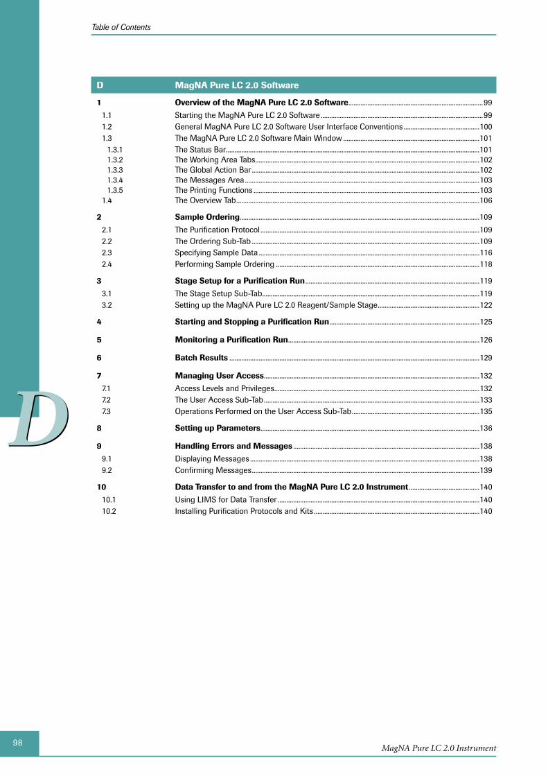
98MagNA Pure LC 2.0 Instrument
Table of Contents
DD
D MagNA Pure LC 2.0 Software
1 Overview of the MagNA Pure LC 2.0 Software ..............................................................................99
1.1 Starting the MagNA Pure LC 2.0 Software ..............................................................................................991.2 General MagNA Pure LC 2.0 Software User Interface Conventions ............................................1001.3 The MagNA Pure LC 2.0 Software Main Window ...............................................................................101
1.3.1 The Status Bar ...................................................................................................................................................1011.3.2 The Working Area Tabs ..................................................................................................................................1021.3.3 The Global Action Bar ....................................................................................................................................1021.3.4 The Messages Area ........................................................................................................................................1031.3.5 The Printing Functions ...................................................................................................................................103
1.4 The Overview Tab .............................................................................................................................................106
2 Sample Ordering ...........................................................................................................................................109
2.1 The Purification Protocol ...............................................................................................................................1092.2 The Ordering Sub-Tab ....................................................................................................................................1092.3 Specifying Sample Data ................................................................................................................................1162.4 Performing Sample Ordering ......................................................................................................................118
3 Stage Setup for a Purification Run .....................................................................................................119
3.1 The Stage Setup Sub-Tab ..............................................................................................................................1193.2 Setting up the MagNA Pure LC 2.0 Reagent/Sample Stage ...........................................................122
4 Starting and Stopping a Purification Run .......................................................................................125
5 Monitoring a Purification Run ...............................................................................................................126
6 Batch Results .................................................................................................................................................129
7 Managing User Access .............................................................................................................................132
7.1 Access Levels and Privileges .......................................................................................................................1327.2 The User Access Sub-Tab .............................................................................................................................1337.3 Operations Performed on the User Access Sub-Tab ..........................................................................135
8 Setting up Parameters ...............................................................................................................................136
9 Handling Errors and Messages ............................................................................................................138
9.1 Displaying Messages .....................................................................................................................................1389.2 Confirming Messages ....................................................................................................................................139
10 Data Transfer to and from the MagNA Pure LC 2.0 Instrument .........................................140
10.1 Using LIMS for Data Transfer .....................................................................................................................14010.2 Installing Purification Protocols and Kits ................................................................................................140

99
DD
MagNA Pure LC 2.0 Software
Overview of the MagNA Pure LC 2.0 Software
Starting the MagNA Pure LC 2.0 Software
MagNA Pure LC 2.0 Software
1 Overview of the MagNA Pure LC 2.0 Software
1.1 Starting the MagNA Pure LC 2.0 SoftwareFollow the steps below to start and log in to the MagNA Pure LC 2.0 Software.
To start the MagNA Pure LC 2.0 Software:
Use the Power On button in the front of the MagNA Pure LC 2.0 Instrument, see sec-tion Start-Up.
The MagNA Pure LC 2.0 Software is started automatically. The application displays the MagNA Pure LC 2.0 Software main window with the Log in window in front.
In the Log in window, type your user name and password.
The name of the last user is displayed, as default in the ‘User name’ field.
Select the Login button to proceed with the log in.
The Log in window closes and the application displays the MagNA Pure LC 2.0 Soft-ware main window containing:
The Status Bar at the top ►The Working Area with the tabs in the middle ►By default the Overview tab is displayed. The Overview tab provides shortcuts to all functions of the MagNA Pure LC 2.0 Software.
The Global Action Bar on the right ►The Messages Area at the bottom ►
For details, see the descriptions in the following sections.
■
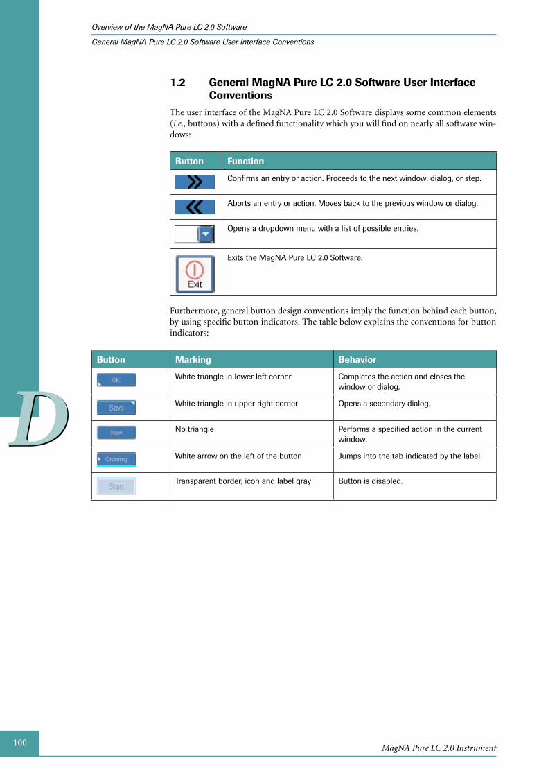
100
DD
MagNA Pure LC 2.0 Instrument
Overview of the MagNA Pure LC 2.0 Software
General MagNA Pure LC 2.0 Software User Interface Conventions
1.2 General MagNA Pure LC 2.0 Software User Interface Conventions
The user interface of the MagNA Pure LC 2.0 Software displays some common elements (i.e., buttons) with a defined functionality which you will find on nearly all software win-dows:
Button Function
Confirms an entry or action. Proceeds to the next window, dialog, or step.
Aborts an entry or action. Moves back to the previous window or dialog.
Opens a dropdown menu with a list of possible entries.
Exits the MagNA Pure LC 2.0 Software.
Furthermore, general button design conventions imply the function behind each button, by using specific button indicators. The table below explains the conventions for button indicators:
Button Marking Behavior
White triangle in lower left corner Completes the action and closes the window or dialog.
White triangle in upper right corner Opens a secondary dialog.
No triangle Performs a specified action in the current window.
White arrow on the left of the button Jumps into the tab indicated by the label.
Transparent border, icon and label gray Button is disabled.
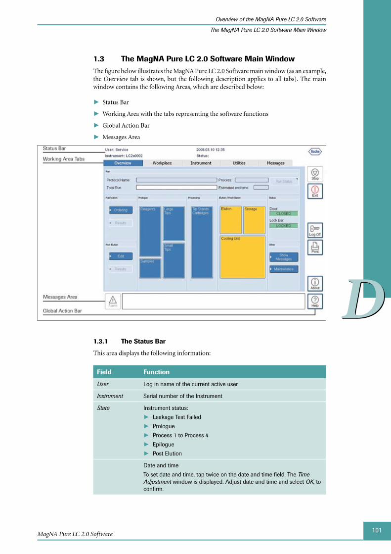
101
DD
MagNA Pure LC 2.0 Software
Overview of the MagNA Pure LC 2.0 Software
The MagNA Pure LC 2.0 Software Main Window
The 1.3 MagNA Pure LC 2.0 Software Main WindowThe figure below illustrates the MagNA Pure LC 2.0 Software main window (as an example, the Overview tab is shown, but the following description applies to all tabs). The main window contains the following Areas, which are described below:
Status Bar ►
Working Area with the tabs representing the software functions ►
Global Action Bar ►
Messages Area ►
1.3.1 The Status Bar
This area displays the following information:
Field Function
User Log in name of the current active user
Instrument Serial number of the Instrument
State Instrument status:
Leakage Test Failed ►Prologue ►Process 1 to Process 4 ►Epilogue ►Post Elution ►
Date and time
To set date and time, tap twice on the date and time field. The Time Adjustment window is displayed. Adjust date and time and select OK, to confirm.
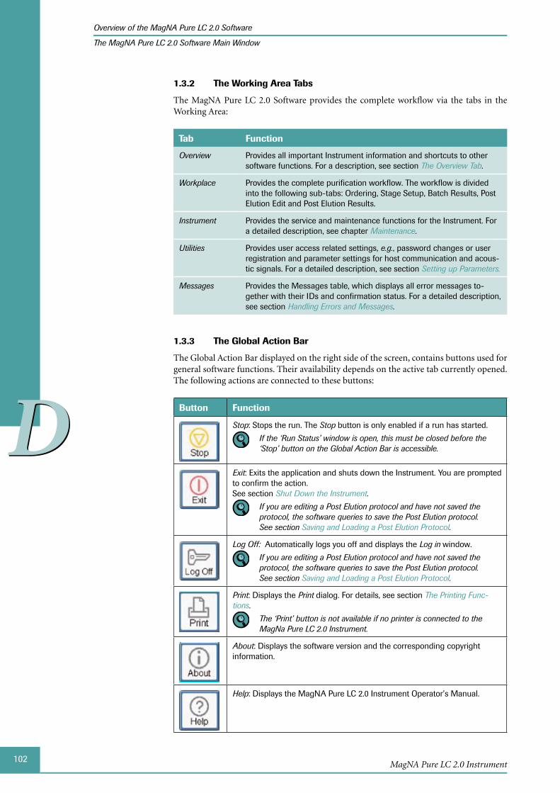
102
DD
MagNA Pure LC 2.0 Instrument
Overview of the MagNA Pure LC 2.0 Software
The MagNA Pure LC 2.0 Software Main Window
The Working Area Tabs1.3.2
The MagNA Pure LC 2.0 Software provides the complete workflow via the tabs in the Working Area:
Tab Function
Overview Provides all important Instrument information and shortcuts to other software functions. For a description, see section The Overview Tab.
Workplace Provides the complete purification workflow. The workflow is divided into the following sub-tabs: Ordering, Stage Setup, Batch Results, Post Elution Edit and Post Elution Results.
Instrument Provides the service and maintenance functions for the Instrument. For a detailed description, see chapter Maintenance.
Utilities Provides user access related settings, e.g., password changes or user registration and parameter settings for host communication and acous-tic signals. For a detailed description, see section Setting up Parameters.
Messages Provides the Messages table, which displays all error messages to-gether with their IDs and confirmation status. For a detailed description, see section Handling Errors and Messages.
1.3.3 The Global Action Bar
The Global Action Bar displayed on the right side of the screen, contains buttons used for general software functions. Their availability depends on the active tab currently opened. The following actions are connected to these buttons:
Button Function
Stop: Stops the run. The Stop button is only enabled if a run has started.
If the ‘Run Status’ window is open, this must be closed before the ‘Stop’ button on the Global Action Bar is accessible.
Exit: Exits the application and shuts down the Instrument. You are prompted to confirm the action. See section Shut Down the Instrument.
If you are editing a Post Elution protocol and have not saved the protocol, the software queries to save the Post Elution protocol. See section Saving and Loading a Post Elution Protocol.
Log Off: Automatically logs you off and displays the Log in window.
If you are editing a Post Elution protocol and have not saved the protocol, the software queries to save the Post Elution protocol. See section Saving and Loading a Post Elution Protocol.
Print: Displays the Print dialog. For details, see section The Printing Func-tions.
The ‘Print’ button is not available if no printer is connected to the MagNa Pure LC 2.0 Instrument.
About: Displays the software version and the corresponding copyright information.
Help: Displays the MagNA Pure LC 2.0 Instrument Operator’s Manual.
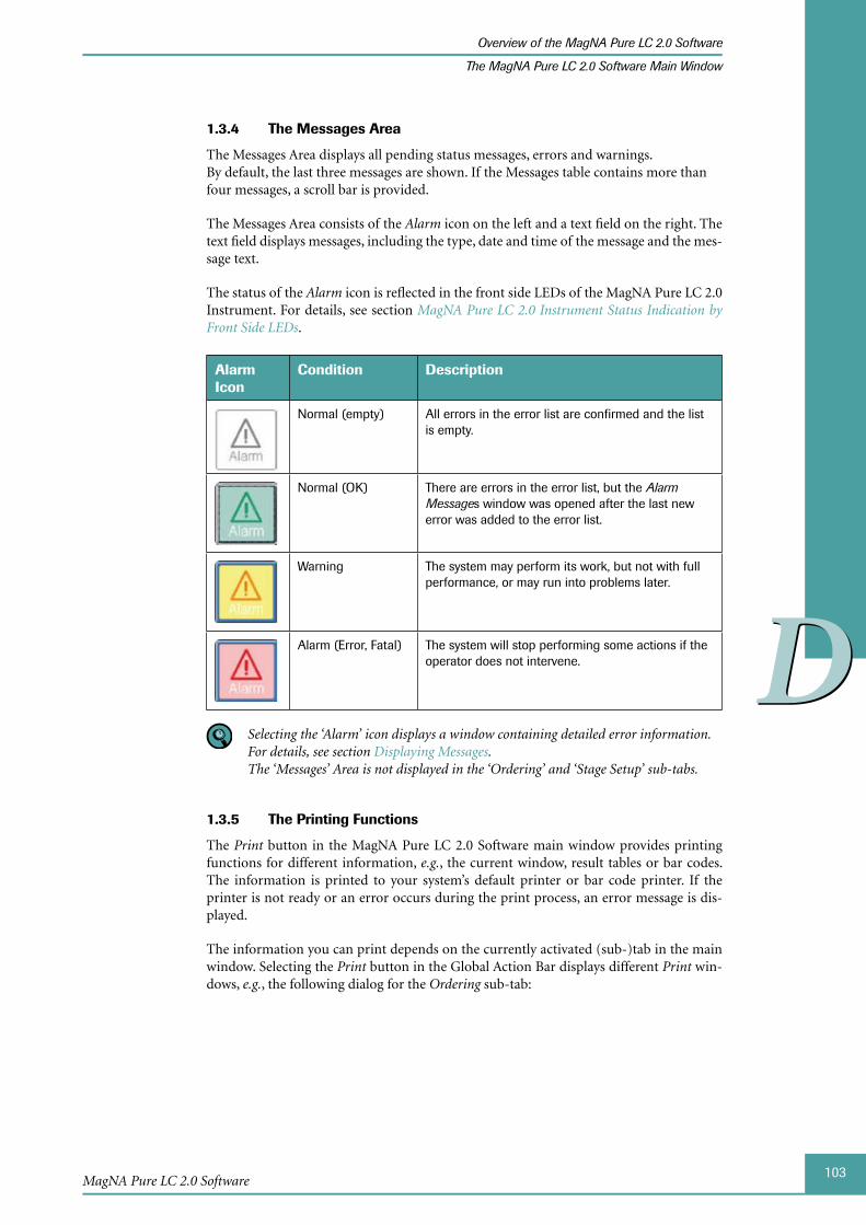
103
DD
MagNA Pure LC 2.0 Software
Overview of the MagNA Pure LC 2.0 Software
The MagNA Pure LC 2.0 Software Main Window
1.3.4 The Messages Area
The Messages Area displays all pending status messages, errors and warnings. By default, the last three messages are shown. If the Messages table contains more than four messages, a scroll bar is provided.
The Messages Area consists of the Alarm icon on the left and a text field on the right. The text field displays messages, including the type, date and time of the message and the mes-sage text.
The status of the Alarm icon is reflected in the front side LEDs of the MagNA Pure LC 2.0 Instrument. For details, see section MagNA Pure LC 2.0 Instrument Status Indication by Front Side LEDs.
Alarm Icon
Condition Description
Normal (empty) All errors in the error list are confirmed and the list is empty.
Normal (OK) There are errors in the error list, but the Alarm Messages window was opened after the last new error was added to the error list.
Warning The system may perform its work, but not with full performance, or may run into problems later.
Alarm (Error, Fatal) The system will stop performing some actions if the operator does not intervene.
Selecting the ‘Alarm’ icon displays a window containing detailed error information. For details, see section Displaying Messages. The ‘Messages’ Area is not displayed in the ‘Ordering’ and ‘Stage Setup’ sub-tabs.
The 1.3.5 Printing Functions
The Print button in the MagNA Pure LC 2.0 Software main window provides printing functions for different information, e.g., the current window, result tables or bar codes. The information is printed to your system’s default printer or bar code printer. If the printer is not ready or an error occurs during the print process, an error message is dis-played.
The information you can print depends on the currently activated (sub-)tab in the main window. Selecting the Print button in the Global Action Bar displays different Print win-dows, e.g., the following dialog for the Ordering sub-tab:
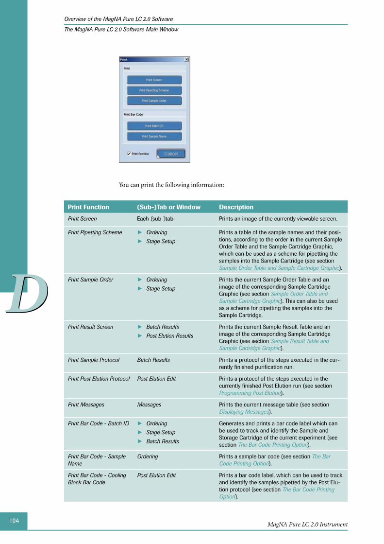
104
DD
MagNA Pure LC 2.0 Instrument
Overview of the MagNA Pure LC 2.0 Software
The MagNA Pure LC 2.0 Software Main Window
You can print the following information:
Print Function (Sub-)Tab or Window Description
Print Screen Each (sub-)tab Prints an image of the currently viewable screen.
Print Pipetting Scheme Ordering ►Stage Setup ►
Prints a table of the sample names and their posi-tions, according to the order in the current Sample Order Table and the Sample Cartridge Graphic, which can be used as a scheme for pipetting the samples into the Sample Cartridge (see section Sample Order Table and Sample Cartridge Graphic).
Print Sample Order Ordering ►Stage Setup ►
Prints the current Sample Order Table and an image of the corresponding Sample Cartridge Graphic (see section Sample Order Table and Sample Cartridge Graphic). This can also be used as a scheme for pipetting the samples into the Sample Cartridge.
Print Result Screen Batch Results ►Post Elution Results ►
Prints the current Sample Result Table and an image of the corresponding Sample Cartridge Graphic (see section Sample Result Table and Sample Cartridge Graphic).
Print Sample Protocol Batch Results Prints a protocol of the steps executed in the cur-rently finished purification run.
Print Post Elution Protocol Post Elution Edit Prints a protocol of the steps executed in the currently finished Post Elution run (see section Programming Post Elution).
Print Messages Messages Prints the current message table (see section Displaying Messages).
Print Bar Code - Batch ID Ordering ►Stage Setup ►Batch Results ►
Generates and prints a bar code label which can be used to track and identify the Sample and Storage Cartridge of the current experiment (see section The Bar Code Printing Option).
Print Bar Code - Sample Name
Ordering Prints a sample bar code (see section The Bar Code Printing Option).
Print Bar Code - Cooling Block Bar Code
Post Elution Edit Prints a bar code label, which can be used to track and identify the samples pipetted by the Post Elu-tion protocol (see section The Bar Code Printing Option).

105
DD
MagNA Pure LC 2.0 Software
Overview of the MagNA Pure LC 2.0 Software
The MagNA Pure LC 2.0 Software Main Window
The Bar Code Printing Option
You can print different bar codes depending on the current tab, e.g., sample, cartridge or Cooling Block Bar Codes:
Bar code Function
Sample Name
Prints a sample bar code. To print a bar code, select a sample line in the Sample Order Table.
Printing a sample bar code serves two functions:
If you start from primary samples which are bar code labeled and ►you scan the bar code into the Name field of the Sample Order Table, you may print this bar code again for labeling of storage ves-sels into which the eluate might be transferred.
If you start from primary samples which are not bar code labeled ►you can use this function to create a bar code label from scratch. In this case, manually enter a valid bar code into the sample name field of the Sample Order Table. Select the respective sample line to print the bar code.
Batch ID Generates and prints a bar code label which can be used to track and identify the Sample and Storage Cartridge of the current experiment.
The cartridge bar code is created by the software. It is identical to the Batch identification Number (Batch ID) of the current purification run.
The Batch ID consists of the last four digits of the Instrument’s serial number, followed by the date in YYMMDD format, then followed by the run counter number, e.g., 00020805190001:
Serial Number Date Run Counter
0002 080519 0001
The bar code can subsequently be scanned for naming of the Sample Order and Results file (if an optional Bar code scanner is installed). When you want to re-load the Sample Order or Results file, simply scan the bar code from the Storage Cartridge into the Sample Name field of the Result Query window.
Cooling Block Bar Code
Prints a bar code label, which can be used to track and identify the samples pipetted by Post Elution. If performed in combination with a prior purification run, the Cooling Block Bar Code will be identical to the BatchID of the purification run.
If two Cooling Blocks were used in the Post Elution run, the Cooling Block Bar Code for the left Cooling Block will have the figure ‘1’ added to the end of the bar code and the bar code for the right Cooling Block will have the figure ‘2’ added to the end.
The bar code is printed on the bar code printer automatically , when a bar code print-er is connected to the Instrument.
If two Post Elution runs are performed using samples from the same purification run, the Cooling Block Bar Code will be identical. It is recommended to change one of the bar codes to differentiate between the Post Elution runs.
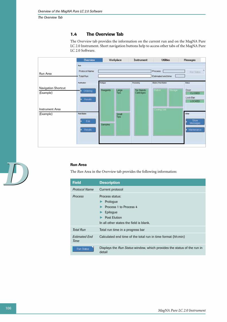
106
DD
MagNA Pure LC 2.0 Instrument
Overview of the MagNA Pure LC 2.0 Software
The Overview Tab
The Overview 1.4 TabThe Overview tab provides the information on the current run and on the MagNA Pure LC 2.0 Instrument. Short navigation buttons help to access other tabs of the MagNA Pure LC 2.0 Software.
Run Area
Navigation Shortcut
(Example)
Instrument Area
(Example)
Run Area
The Run Area in the Overview tab provides the following information:
Field Description
Protocol Name Current protocol
Process Process status:
Prologue ►Process 1 to Process 4 ►Epilogue ►Post Elution ►
In all other states the field is blank.
Total Run Total run time in a progress bar
Estimated End Time
Calculated end time of the total run in time format (hh:min)
Displays the Run Status window, which provides the status of the run in detail
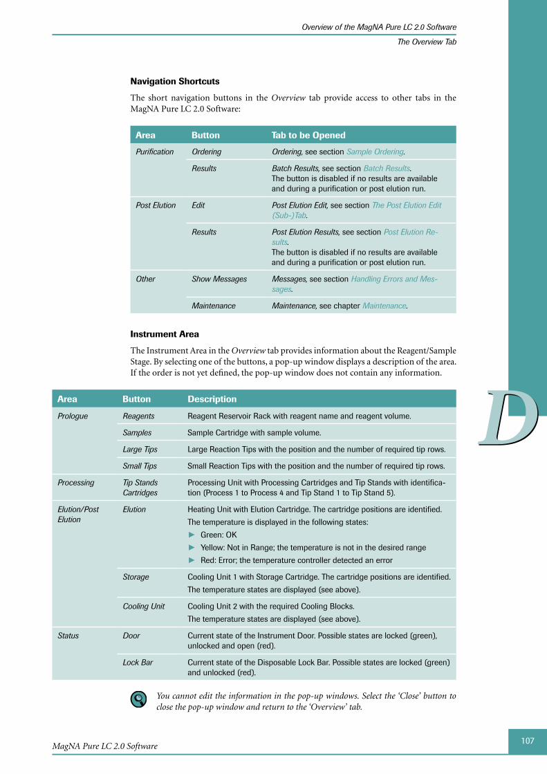
107
DD
MagNA Pure LC 2.0 Software
Overview of the MagNA Pure LC 2.0 Software
The Overview Tab
Navigation Shortcuts
The short navigation buttons in the Overview tab provide access to other tabs in the MagNA Pure LC 2.0 Software:
Area Button Tab to be Opened
Purification Ordering Ordering, see section Sample Ordering.
Results Batch Results, see section Batch Results. The button is disabled if no results are available and during a purification or post elution run.
Post Elution Edit Post Elution Edit, see section The Post Elution Edit (Sub-)Tab.
Results Post Elution Results, see section Post Elution Re-sults. The button is disabled if no results are available and during a purification or post elution run.
Other Show Messages Messages, see section Handling Errors and Mes-sages.
Maintenance Maintenance, see chapter Maintenance.
Instrument Area
The Instrument Area in the Overview tab provides information about the Reagent/Sample Stage. By selecting one of the buttons, a pop-up window displays a description of the area. If the order is not yet defined, the pop-up window does not contain any information.
Area Button Description
Prologue Reagents Reagent Reservoir Rack with reagent name and reagent volume.
Samples Sample Cartridge with sample volume.
Large Tips Large Reaction Tips with the position and the number of required tip rows.
Small Tips Small Reaction Tips with the position and the number of required tip rows.
Processing Tip Stands Cartridges
Processing Unit with Processing Cartridges and Tip Stands with identifica-tion (Process 1 to Process 4 and Tip Stand 1 to Tip Stand 5).
Elution/Post Elution
Elution Heating Unit with Elution Cartridge. The cartridge positions are identified.
The temperature is displayed in the following states:
Green: OK ►Yellow: Not in Range; the temperature is not in the desired range ►Red: Error; the temperature controller detected an error ►
Storage Cooling Unit 1 with Storage Cartridge. The cartridge positions are identified.
The temperature states are displayed (see above).
Cooling Unit Cooling Unit 2 with the required Cooling Blocks.
The temperature states are displayed (see above).
Status Door Current state of the Instrument Door. Possible states are locked (green), unlocked and open (red).
Lock Bar Current state of the Disposable Lock Bar. Possible states are locked (green) and unlocked (red).
You cannot edit the information in the pop-up windows. Select the ‘Close’ button to close the pop-up window and return to the ‘Overview’ tab.

108
DD
MagNA Pure LC 2.0 Instrument
Overview of the MagNA Pure LC 2.0 Software
The Overview Tab
The buttons in the Prologue, Processing and Elution/Post Elution areas are color-coded:
Blue: No order prepared. The detail view is not defined. ►
Green: An order is prepared. All elements shown in the detail view were confirmed in ►the Stage Setup sub-tab. Additionally all active monitored values (e.g., temperature) are in range.
Yellow: An order is prepared. One or more elements shown in the detail view are not ►confirmed yet in the Stage Setup sub-tab.
Red: One or more of the active monitored values ( ► e.g., temperature, reagent level, tips etc.) has failed.
If you leave the Stage Setup sub-tab, the status of all elements is set to Not Confirmed.

109
DD
MagNA Pure LC 2.0 Software
Sample Ordering
The Purification Protocol
2 Sample OrderingBefore starting a purification run, the user must provide the software with the neces-sary information on protocol and sample parameters. The most important and obligatory ones are:
Purification protocol, see section ► The Purification Protocol below
Amount of sample and elution volume, see section ► The Ordering Sub-Tab
Number and name of samples, see section ► Specifying Sample Data
Provided with this information the software calculates the type and amount of isolation reagents and disposable plastics.
This information is entered on the Ordering sub-tab, see section The Ordering Sub-Tab.
The 2.1 Purification ProtocolFor every MagNA Pure LC Kit a specific purification protocol exists. The purification pro-tocol contains the information about the isolation reagents included in the kit, the order of the pipetting steps and the incubation times for the various reaction steps of the purifi-cation procedure. For some kits, more than one purification protocol may exist, if specific instructions for different sample materials or variant grades of purification are possible.
Purification protocols are pre-installed together with the MagNA Pure LC 2.0 Software. If new MagNA Pure LC Kits are offered or additional protocols for further sample materials are available, new purification protocols can be installed, see section Installing Purification Protocols and Kits.
The purification protocols installed together with the MagNA Pure LC 2.0 Software are listed in the Appendix, section Installed Purification Protocols.
The 2.2 Ordering Sub-TabInput of sample and protocol parameters is done on the Ordering sub-tab.
To open the Ordering sub-tab:
Open the Workplace tab in the MagNA Pure LC 2.0 Software.
On the Workplace tab, select Ordering.
The Ordering sub-tab is displayed.
■
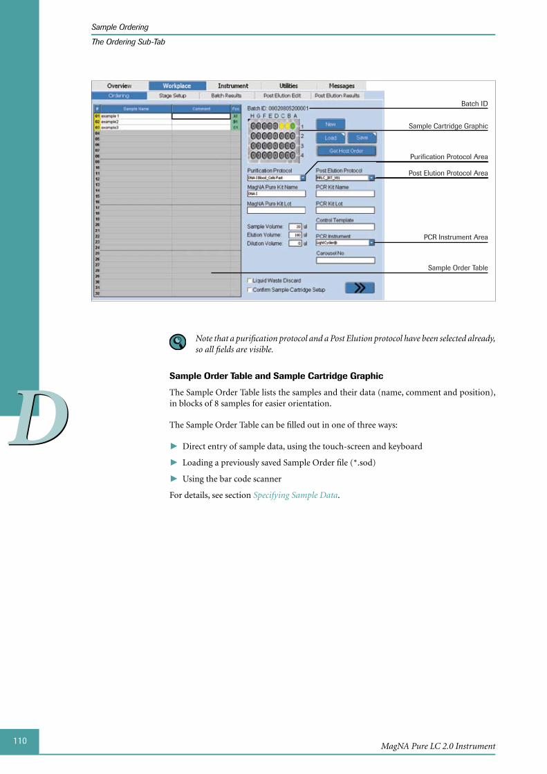
110
DD
MagNA Pure LC 2.0 Instrument
Sample Ordering
The Ordering Sub-Tab
Batch ID
Sample Cartridge Graphic
Sample Order Table
Purification Protocol Area
Post Elution Protocol Area
PCR Instrument Area
Note that a purification protocol and a Post Elution protocol have been selected already, so all fields are visible.
Sample Order Table and Sample Cartridge Graphic
The Sample Order Table lists the samples and their data (name, comment and position), in blocks of 8 samples for easier orientation.
The Sample Order Table can be filled out in one of three ways:
Direct entry of sample data, using the touch-screen and keyboard ►
Loading a previously saved Sample Order file (*.sod) ►
Using the bar code scanner ►
For details, see section Specifying Sample Data.

111
DD
MagNA Pure LC 2.0 Software
Sample Ordering
The Ordering Sub-Tab
Column Description
# Sample number. The software automatically assigns the sample num-bers, as the user enters each set of sample information.
Sample Name Sample name. For a description on how to enter the sample names, see section Specifying Sample Data.
Comment Optional: Description of the sample.
Pos Well coordinate of the sample in the Sample Cartridge.
You must fill in the Sample Order Table row by row without any gaps, starting with the first row. Otherwise an error message appears when selecting the ‘Continue’ button. It is not possible to start the purification run.
The Sample Cartridge Graphic represents the samples in detail. It can be used for assign-ing a sample to a particular position in the Sample Cartridge during Sample Ordering.
The rows in the Sample Cartridge are labeled 1-4 (vertically); in each row, the wells are ►labeled A-H from right to left (horizontally).
The wells are displayed color-coded according to their status. ►
Green: the sample is selected ►
Yellow: the sample is loaded ►
Gray: the well is still empty ►
The sample selection in the Sample Order Table and Sample Cartridge Graphic are linked:
When one or more of the rows in the Sample Order Table is selected and colored ►blue, the corresponding samples in the Sample Cartridge Graphic are displayed green (selected).
When a sample in the Sample Cartridge Graphic is selected, it is displayed in green ►and the Sample Name field of the corresponding sample in the Sample Order Table is activated.
Batch ID
The Batch ID is displayed above the Sample Cartridge Graphic. The Batch ID is used to distinguish the order between the host and the MagNA Pure LC 2.0 Instrument. It consists of the last four digits of the Instrument’s serial number, followed by the date in YYMMDD format, then followed by the run counter number.
The counter is increased automatically for each purification run.

112
DD
MagNA Pure LC 2.0 Instrument
Sample Ordering
The Ordering Sub-Tab
Buttons
Button Function
New Clears the Sample Order Table and all other entry and data fields of the Ordering sub-tab (after confirmation), see section To specify new sample names:.
Use this function if you want to prepare a new Sample Order.
Load Loads a previously saved Sample Order File (*.sod). Entry and data fields of the Ordering sub-tab are cleared (after confirmation), see section To load an existing sample order:.
Save Saves the Sample Ordering data as a Sample Order File (*.sod) for re-use in subsequent purification runs. For details, see section To save a sample order:.
Get Host Order
Entry and data fields of the Ordering sub-tab are cleared (after confirma-tion), see section To use a host connection to specify a sample order:.
This functionality is not available if the MagNA Pure LC 2.0 Instrument is not connected to a LIMS. For detailed information on LIMS, see section Using LIMS for Data Transfer.
Before using this function, you must create a batch order with a unique Sample Cartridge Bar Code (Batch ID) on LIMS. The Batch ID must be unique and may only contain numbers.
Purification Protocol Area
The input fields in the Purification Protocol Area depend on the current settings for the purification protocol.
Field Description
Purification Protocol
Dropdown menu to select the purification protocol.
For detailed descriptions of the different Purification Protocols, see section The Purification Protocol.
When you access the ‘Ordering’ sub-tab for the first time, the ‘Purification Protocol’ field displays ‘None’, which means that no protocol is selected. In this case, the corresponding input fields for the MagNA Pure LC Kit and the sample volumes are hidden.
A protocol selection is saved, even if you leave the ‘Ordering’ sub-tab or the software itself. The next time you access the ‘Ordering’ sub-tab again, the name of the last selected protocol is displayed. If you want to start with an empty ‘Ordering’ sub-tab, select ‘New’.
After you have selected a protocol, further input fields are displayed:
MagNA Pure Kit Name
When the purification protocol is selected, the corresponding MagNA Pure LC Kit name is displayed automatically.
MagNA Pure Kit Lot
Optional: Lot number of the MagNA Pure LC Kit. This lot number is stored for documentation purposes.
Sample Volume Sample volume that is pipetted into the wells of the Sample Cartridge.
If you select a purification protocol that is based on an external pre-treatment of the sample (e.g., Total_NA External_Lysis) you should not enter the volume of the primary sample, but the volume of the complete lysate.
Elution Volume Volume of elution buffer in which the nucleic acid is eluted from the Magnetic Glass Particles within the Elution Cartridge.
113
DD
MagNA Pure LC 2.0 Software
Sample Ordering
The Ordering Sub-Tab
Field Description
Dilution Volume Optional: For dilution of eluted nucleic acid samples, an additional amount of Elution Buffer is pre-pipetted into the wells of the Storage Cartridge.
If you select a dilution volume, an additional Reagent Tub will be required for storage of the Elution Buffer used for eluate dilution. This additional Reagent Tub is always a Medium Reagent Tub M30 and is placed in position 7 of the Reagent Reservoir Rack, when performing a DNA isolation run, or in position 8, when performing a Total Nucleic Acid isolation run.
For every purification protocol, a minimum and maximum sample, elution and dilution volume is defined in the software. It is not possible to start a purification run if an entered volume exceeds the allowed range. Place the cursor over the respective the field to display the possible volume range.
After selecting a purification protocol, recommended default values for sample and elution volume are automatically entered into the respective fields by the software.
If you select a purification protocol that is based on an external pre-treatment of the sample (e.g., Total_NA External_Lysis) you should not enter the volume of the pri-mary sample, but the volume of the complete lysate.
114
DD
MagNA Pure LC 2.0 Instrument
Sample Ordering
The Ordering Sub-Tab
Post Elution Protocol Area and PCR Instrument Area
Field Description
Post Elution Protocol
Dropdown menu to select the Post Elution protocol.
The selected Post Elution protocol will start directly after completion of the purification process, except if an error has occurred during the purification run.
Post Elution protocol files must be stored within the directory ‘..\MagNAPure\Protocols\PostElution’, in order to select them from the ‘Post Elution Protocol’ menu.
Note that there will be no pausing between the purification run and the Post Elution run. Therefore, all reagents and disposable plastics required for Post Elution must be placed on the Reagent/Sample Stage in advance. Also, ensure that the volume of the eluted samples is sufficient for the Post Elution protocol.
After you have selected a protocol, further input fields are displayed:
PCR Kit Name Optional: Name of the (RT-) PCR kit used in the master mix for docu-mentation purposes.
PCR Kit Lot Optional: Lot Number of the (RT-) PCR Kit used in the master mix for documentation purposes.
Control Template
Optional: Lot-specific information (e.g., heterozygous plasmid control when performing a mutation detection).
PCR Instrument Dropdown menu to select the PCR Instrument. Depending on the selected PCR Instrument, an additional input field is displayed. The fol-lowing PCR Instruments are available:
LightCycler ► ® Carousel-Based System (default PCR Instrument): The input field Carousel No. is displayed. You can specify the carou-sel number for identification purposes here. This might be neces-sary if you use nucleic acids isolated on the MagNA Pure LC 2.0 Instrument as template for a subsequent LightCycler® PCR and you have several LightCycler® Sample Carousels.
LC480 ► : The input field Plate ID is displayed. You can specify the bar code present on the LightCycler® 480 Multiwell Plate 96.
Other ► : The input field PCR Setup is displayed. You can specify if PCR tubes or a PCR plate is used. Alternatively a bar code can be inputted, if available.
Entries in the fields: ‘PCR Kit Name’, ‘PCR Kit Lot’ and ‘Control Template’ are op-tional. Entries are stored within a saved Sample Order or Result Screen file for docu-mentation purposes. In addition, results can be transferred to a LightCycler® SAM-file or a LightCycler® 480 file that can be generated from the ‘Post Elution Results’ sub-tab.
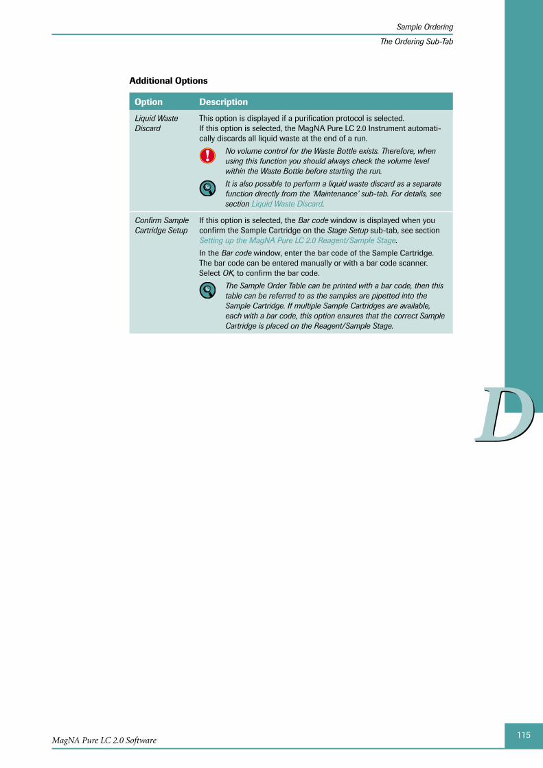
115
DD
MagNA Pure LC 2.0 Software
Sample Ordering
The Ordering Sub-Tab
Additional Options
Option Description
Liquid Waste Discard
This option is displayed if a purification protocol is selected. If this option is selected, the MagNA Pure LC 2.0 Instrument automati-cally discards all liquid waste at the end of a run.
No volume control for the Waste Bottle exists. Therefore, when using this function you should always check the volume level within the Waste Bottle before starting the run.
It is also possible to perform a liquid waste discard as a separate function directly from the ‘Maintenance’ sub-tab. For details, see section Liquid Waste Discard.
Confirm Sample Cartridge Setup
If this option is selected, the Bar code window is displayed when you confirm the Sample Cartridge on the Stage Setup sub-tab, see section Setting up the MagNA Pure LC 2.0 Reagent/Sample Stage.
In the Bar code window, enter the bar code of the Sample Cartridge. The bar code can be entered manually or with a bar code scanner. Select OK, to confirm the bar code.
The Sample Order Table can be printed with a bar code, then this table can be referred to as the samples are pipetted into the Sample Cartridge. If multiple Sample Cartridges are available, each with a bar code, this option ensures that the correct Sample Cartridge is placed on the Reagent/Sample Stage.
116
DD
MagNA Pure LC 2.0 Instrument
Sample Ordering
Specifying Sample Data
2.3 Specifying Sample DataThe names and positions of all samples pipetted into the Sample Cartridge must be speci-fied in the Sample Order Table before starting a purification run. Each sample in the Sample Cartridge must be named individually. You must fill in the Sample Order Table beginning with the first row. Enter the samples into the Sample Order Table row by row without any gaps.
You can specify the sample data in different ways:
Entering new sample names, either by using the keyboard or bar code scanner ►
Loading a previously saved Sample Order File (.SOD) ►
Use a sample order from an external host ►
In addition to sample data, the SOD-file contains protocol information, which will overwrite any protocol information previously specified.
To specify new sample names:
Select the field Sample Name in the Sample Order Table, beginning with row 1.
Enter the sample name.
You can enter the sample names manually with the keyboard or automatically with a bar code scanner.
■
You can also select a well in the Sample Cartridge Graphic. The selected well changes to green. The corresponding field ‘Sample Name’ in the Sample Order Table is acti-vated automatically. The position A1 corresponds to row 1 in the Sample Order Table. Enter the sample names starting with the top row and naming the samples right to left.
To load an existing sample order:
Select Load on the Ordering sub-tab.
A pop-up window is displayed asking to clear all Sample Ordering Information. Confirm the message to continue.
All specified sample ordering data is cleared.
The Open window is displayed. Select the SOD-file to be loaded and confirm the selection with Open.
The sample information from the Sample Order file is loaded and displayed on the screen.
■
By default the pre-defined folder to load orders as templates is displayed. If a USB stick is connected to the MagNA Pure LC 2.0 Instrument, a template can be selected from the USB directory as well.

117
DD
MagNA Pure LC 2.0 Software
Sample Ordering
Specifying Sample Data
To use a host connection to specify a sample order:
If you want to use sample data edited on an external host, you must send the data from the host to the MagNA Pure LC 2.0 Instrument. When the ordering data arrives, a cor-responding message is displayed and the Get Host Order button on the Ordering sub-tab is activated.
Select Get Host Order on the Ordering sub-tab.
The Order Lookup window is displayed. Enter the Batch ID of the sample order you want to use.
Select OK.
If the system receives a valid sample order, it will be displayed on the screen. This value cannot be modified.
■
To save a sample order:
If you have specified a sample order, you can save the data in a Sample Order File (.SOD).
Select Save on the Ordering sub-tab.
The Save as window is displayed.
Select the device, or directory where the SOD-file should be saved. Enter the name of the SOD-file you want to save and confirm by selecting Save.
■
By default the pre-defined folder to save sample orders as templates is displayed. Sub-folders can be created to organize the templates. If a USB stick is connected to the MagNA Pure LC 2.0 Instrument, the template can be saved in the USB directory.
118
DD
MagNA Pure LC 2.0 Instrument
Sample Ordering
Performing Sample Ordering
Performing 2.4 Sample OrderingTo perform sample ordering, you must work through the Ordering sub-tab. You must spec-ify the sample data, the purification protocol and the Post Elution protocol, if required.
Specify the sample data in the Sample Order Table with the names and positions of all samples placed into the Sample Cartridge. You can:
Enter new sample names, see section ► To specify new sample names:.
Load an existing Sample Order File and edit the Sample Order information, if nec- ►essary, see section To load an existing sample order:.
Load sample data from an external host, see section ► To use a host connection to specify a sample order:.
In the Purification Protocol field, choose the appropriate purification protocol, see sec-tion Installed Purification Protocols.
When you access the ‘Ordering’ sub-tab for the first time, the ‘Purification Protocol’ field displays ‘None’, which means that no protocol is selected. In this case the corresponding fields for the MagNA Pure LC Kit and the sample volumes are hidden.
After selecting the Purification Protocol, further input fields are displayed. The cor-responding MagNA Pure LC Kit name is displayed in the MagNA Pure Kit Name field automatically.
In the MagNA Pure Kit Lot field, enter the lot number of the MagNA Pure LC Kit.
In the Volume fields enter the volume for:
The sample that is pipetted into the wells of the Sample Cartridge. ►The elution buffer in which the nucleic acid is eluted from the Magnetic Glass ►Particles within the Elution Cartridge.
Optional: the dilution buffer. ► After selecting a purification protocol, recommended default values for sample
and elution volume are automatically entered into the respective fields by the software.
In the Post Elution Protocol field, choose the appropriate Post Elution protocol.
Optional: In the PCR Kit Name field and the PCR Kit Lot field, enter the kit name and the kit lot number of the (RT-)PCR Kit in the master mix.
Optional: In the Control Template field, enter the lot-specific information of the control template.
In the PCR Instrument field, choose the appropriate PCR Instrument.
Depending on the selected PCR Instrument, an additional input field is displayed.
Optional: Enter further information about the PCR Instrument in the additional input field (Carousel No., Plate ID or PCR Setup).
Select the Liquid Waste Discard option, if the MagNA Pure LC 2.0 Instrument should automatically discard all liquid waste at the end of the run.
Select the Confirm Sample Cartridge Setup option, if you want the Bar code window to be displayed when you confirm the Sample Cartridge on the Stage Setup sub-tab, see section Additional Options.
Select the Continue button to finish sample ordering. The Stage Setup sub-tab is dis-played, see the following section.
The ‘Continue’ button is disabled if the sample ordering data is incomplete or false (e.g., the data in the Sample Order Table is not entered continuously).
■
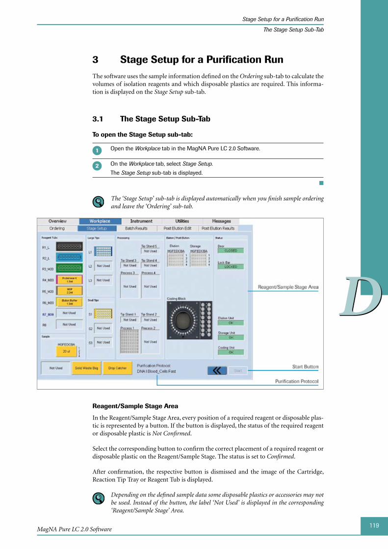
119
DD
MagNA Pure LC 2.0 Software
Stage Setup for a Purification Run
The Stage Setup Sub-Tab
3 Stage Setup for a Purification RunThe software uses the sample information defined on the Ordering sub-tab to calculate the volumes of isolation reagents and which disposable plastics are required. This informa-tion is displayed on the Stage Setup sub-tab.
The 3.1 Stage Setup Sub-Tab
To open the Stage Setup sub-tab:
Open the Workplace tab in the MagNA Pure LC 2.0 Software.
On the Workplace tab, select Stage Setup.
The Stage Setup sub-tab is displayed.
■
The ‘Stage Setup’ sub-tab is displayed automatically when you finish sample ordering and leave the ‘Ordering’ sub-tab.
Reagent/Sample Stage Area
In the Reagent/Sample Stage Area, every position of a required reagent or disposable plas-tic is represented by a button. If the button is displayed, the status of the required reagent or disposable plastic is Not Confirmed.
Select the corresponding button to confirm the correct placement of a required reagent or disposable plastic on the Reagent/Sample Stage. The status is set to Confirmed.
After confirmation, the respective button is dismissed and the image of the Cartridge, Reaction Tip Tray or Reagent Tub is displayed.
Depending on the defined sample data some disposable plastics or accessories may not be used. Instead of the button, the label ‘Not Used’ is displayed in the corresponding ‘Reagent/Sample Stage’ Area.

120
DD
MagNA Pure LC 2.0 Instrument
Stage Setup for a Purification Run
The Stage Setup Sub-Tab
Area Displayed Information
Reagent Tubs The eight Reagent Tubs are listed in eight rows (R1 to R8).
Depending on the selected protocol the type of the Reagent Tub is indi-cated:
L: Large Reagent Tub ►M20: Medium Reagent Tub M20 ►M30: Medium Reagent Tub M30 (the M30 label is displayed in bold, ►blue letters to avoid a mix up with the M20 label)
S: Small Reagent Tub ►The type and volume of isolation reagent or buffer, that must be pipetted into the Reagent Tub, is displayed (e.g., Proteinase K, 2.6 ml).
The Reagent Tub buttons are underlaid with the color of the correspond-ing Reagent Bottle lid. The same colors are found on the Positioning Frames available for placement on the Reagent Reservoir Rack. For a detailed description of the Positioning Frames, see section To Place the MagNA Pure LC Rea gent Tubs and Isolation Reagents.
After confirmation, the Reagent Reservoir Rack is displayed.
Samples Specified amount of the sample volume.
After confirmation, the Sample Cartridge is displayed. The positions filled with samples are marked in yellow.
Large Tips The three Large Tip Trays are shown in three buttons (L1 to L3). For each Tip Tray, the number of required rows of Large Reaction Tips is displayed.
After confirmation, a Large Tip Tray is displayed.
Small Tips The three Small Tip Trays are shown in three buttons (S1 to S3). For each Tip Tray, the number of required rows of Small Reaction Tips is displayed.
After confirmation, a Small Tip Tray is displayed.
Processing Tip Stand 1 to 5 ► : Required number of Tip Stands. After confirmation, a Tip Stand is displayed.
Process 1 to 4 ► : Required number of Processing Cartridges. After confirmation, a Processing Cartridge is displayed.
Elution/Post Elution
Elution Cartridge ► : After confirmation, the Elution Cartridge is displayed.
Storage Cartridge ► : After confirmation, the Storage Cartridge is displayed.
Cooling Block ► : After confirmation, the required Cooling Blocks are displayed (depending on the selected Post Elution protocol).
Status Door ► : Status of the Instrument Door. Possible states are open (red) and closed (green).
The Instrument Door must be closed (green) to start the purification run.
Lock Bar ► : Status of the Disposable Lock Bar. Possible states are unlocked (red) and locked (green).
The Disposable Lock Bar must be locked (green) to start the purifica-tion run.
Elution Unit ► /Storage Unit/Cooling Unit: Thermal state of the respective unit. Possible states are:
Fail (red): The target temperature has not yet been reached. ►OK (green): The target temperature has been reached. ►
You can start a purification run if the status is not ‘OK’ for all Heating/Cooling Units. The MagNA Pure LC 2.0 Instrument waits for the correct state automatically, before starting the run. See description of the ‘Start’ button below for detailed information on this behavior.
121
DD
MagNA Pure LC 2.0 Software
Stage Setup for a Purification Run
The Stage Setup Sub-Tab
Area Displayed Information
Liquid Waste After confirmation, the Waste Bottle is displayed.
Liquid Waste is only available if the ‘Liquid Waste Discard’ option has been activated on the ‘Ordering’ sub-tab, see section Additional Options.
Solid Waste Bag
After confirmation, the solid Waste Bag is displayed.
Drop Catcher After confirmation, the Liquid Drop Catcher is displayed.
Purification Protocol
The currently used purification protocol is displayed in the bottom line of the Stage Setup sub-tab.
Start Button
The Start Button is only active after confirmation of the correct placement of all required reagents and disposable plastics.
Button Description
Start Starts a purification run.
The ‘Start’ Button is active also when the Heating and Cooling Units have not yet reached their final target temperature. You are able to start the run immediately, but the actual process will not start before the required Heating and Cooling Unit tem-peratures are reached. It might take up to 25 min until the final target temperature is reached, beginning with the selection of the respective protocol.
It is recommended to select your protocol and complete all necessary fields in the ‘Ordering’ sub-tab, prior to opening the ‘Stage Setup’ sub-tab. Once the ‘Stage Setup’ sub-tab is selected, the Heating Unit and Cooling Units will start to reach the tempera-ture appropriate for the selected protocol. It is important to pipette the Magnetic Glass Particles as the last reagent, just prior to starting the purification run.
If the MagNA Pure LC 2.0 Instrument is not ready to start within 25 minutes after you started the run, an error message is displayed and the run is aborted. All results become failures.
122
DD
MagNA Pure LC 2.0 Instrument
Stage Setup for a Purification Run
Setting up the MagNA Pure LC 2.0 Reagent/Sample Stage
3.2 Setting up the MagNA Pure LC 2.0 Reagent/Sample Stage
Gloves should be worn during all handling of reagents and disposable plastics, all manipulations steps inside the MagNA Pure LC 2.0 Instrument and all manually performed pipetting steps. Always use sterile, nuclease-free pipettes.
Use the following workflow:
Place the required reagents and disposable plastics one by one on the Reagent/Sample Stage.
After each placement select the respective button of the Reagent/Sample Stage Area of the Stage Setup sub-tab, to confirm the correct placement.
■
The software does not check whether the Reagent/Sample Stage is equipped correctly with reagents and disposable plastics. It relies on your visual inspection of all required items. Ensure the correct item is present, before selecting the corresponding button on the ‘Stage Setup’ sub-tab.
You cannot start the purification run before all positions have been confirmed.
To place the disposable plastics on the MagNA Pure LC 2.0 Reagent/Sample Stage and confirm the correct placement on the Stage Setup sub-tab:
It is recommended to fill the Reagent/Sample Stage in the order described below:
Place the Storage Cartridge into the Cooling Unit, see section Placing the Elution Cartridge and the Storage Cartridge (Stage Position 10/11).
Select the Storage button in the Elution/Post Elution Area, to confirm the correct place-ment.
Place the Elution Cartridge into the Heating Unit, see section Placing the Elution Cartridge and the Storage Cartridge (Stage Position 10/11).
Select the Elution button in the Elution/Post Elution Area, to confirm the correct place-ment.
Place Processing Cartridge(s), see section Placing the MagNA Pure LC Processing Cartridges (Stage Position 9).
Select the Process 1 to Process 4 button(s) in the Processing Area, to confirm the correct placement.
If required: Place Tip Stand(s), see section Placing the MagNA Pure LC Tip Stands (Stage Position 8).
Select the button(s) of the corresponding Tip Stand(s) in the Processing Area, to confirm the correct placement.
Place Large and Small Reaction Tips, see section Placing the MagNA Pure LC Reaction Tips (Stage Position 3/4).
Select the button(s) of the corresponding Reaction Tip Trays in the Large Tips/Small Tips Area, to confirm the correct placement.
Pipette samples into the Sample Cartridge (outside the Instrument), see section Filling and Placing the MagNA Pure LC Sample Cartridge (Stage Position 1).
► ► ►

123
DD
MagNA Pure LC 2.0 Software
Stage Setup for a Purification Run
Setting up the MagNA Pure LC 2.0 Reagent/Sample Stage
Place Sample Cartridge, see section Filling and Placing the MagNA Pure LC Sample Cartridge (Stage Position 1).
Select the button in the Sample Area, to confirm the correct placement.
If the ‘Confirm Sample Cartridge Setup’ option is selected in the ‘Ordering’ sub-tab, see section Additional Options, the ‘Bar Code’ pop-up window is displayed when you confirm the Sample Cartridge. Enter the bar code of the Sample Cartridge. Select ‘OK’ to confirm the bar code.
Check placement of the Waste Bag, see section Placing the MagNA Pure LC 2.0 Waste Bag.
Select the Solid Waste Bag button, to confirm the correct placement.
Check the Waste Bottle, see section Placing the MagNA Pure LC Waste Bottle.
This is only necessary if the ‘Liquid Waste Discard’ option is activated on the ‘Ordering’ sub-tab, see section Additional Options.
Select the Liquid Waste button, to confirm the correct placement.
Place Reagent Tubs into the Reagent Reservoir Rack outside the Instrument, see sec-tion Filling and Placing the MagNA Pure LC Reagent Tubs (Stage Position 2).
Close Reagent Tubs with Tub Lids (outside the Instrument), see section Filling and Placing the MagNA Pure LC Reagent Tubs (Stage Position 2).
Pipette isolation reagents into the Reagent Tubs (outside the Instrument), see section Filling and Placing the MagNA Pure LC Reagent Tubs (Stage Position 2).
Always pipette the Magnetic Glass Particles last, once the Heating Unit and Cooling Units of the Instrument are at the correct temperature with a ‘Green’ status in the ‘Status’ Area. If the pipette is too big to fit through the holes of the Tub Lid, the Reagent Tub can be filled prior to placing the Tub Lid.
Place filled Reagent Tubs within the Reagent Reservoir Rack, see section Filling and Placing the MagNA Pure LC Reagent Tubs (Stage Position 2).
Select the buttons of the corresponding Reagent Tubs in the Reagent Tubs Area, to confirm the correct placement.
After placing the Reagent Reservoir Rack on the Reagent/Sample Stage, close the Disposable Lock Bar, by pushing the handle of the right side of the Disposable Lock Bar down.
Check the Lock Bar state in the Status Area.
Close the MagNA Pure LC 2.0 Instrument Door by pulling down the handle with two hands, using appropriate and reasonable force.
Check the Door state in the Status Area.
■
If you want to perform a Post Elution run directly following the purification run, you may already place MagNA Pure LC Cooling Blocks into Cooling Unit 2, before starting the purification run. Please follow the instructions given in section Positioning MagNA Pure LC Cooling Blocks. Also, ensure that the volume of the eluted samples is sufficient for the Post Elution protocol.
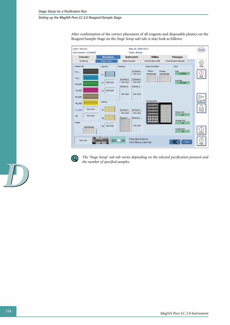
124
DD
MagNA Pure LC 2.0 Instrument
Stage Setup for a Purification Run
Setting up the MagNA Pure LC 2.0 Reagent/Sample Stage
After confirmation of the correct placement of all reagents and disposable plastics on the Reagent/Sample Stage on the Stage Setup sub-tab, it may look as follows:
The ‘Stage Setup’ sub-tab varies depending on the selected purification protocol and the number of specified samples.
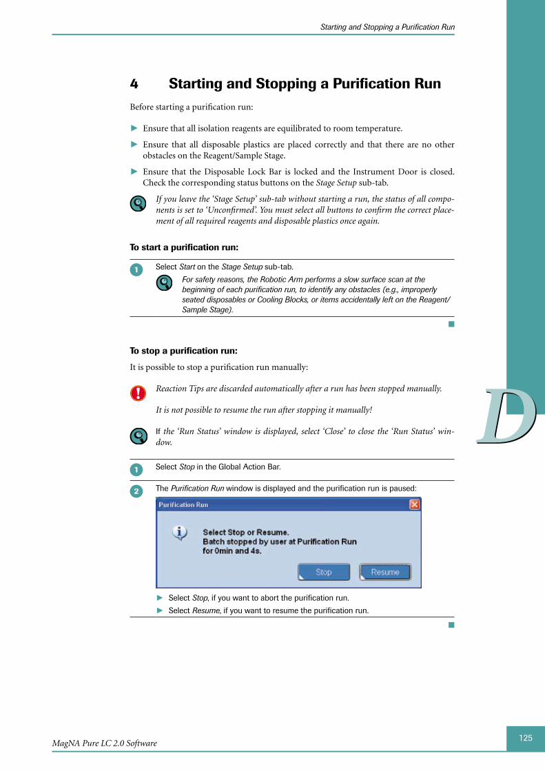
125
DD
MagNA Pure LC 2.0 Software
Starting and Stopping a Purification Run
4 Starting and Stopping a Purification RunBefore starting a purification run:
Ensure that all isolation reagents are equilibrated to room temperature. ►
Ensure that all disposable plastics are placed correctly and that there are no other ► obstacles on the Reagent/Sample Stage.
Ensure that the Disposable Lock Bar is locked and the Instrument Door is closed. ►Check the corresponding status buttons on the Stage Setup sub-tab.
If you leave the ‘Stage Setup’ sub-tab without starting a run, the status of all compo-nents is set to ‘Unconfirmed’. You must select all buttons to confirm the correct place-ment of all required reagents and disposable plastics once again.
To start a purification run:
Select Start on the Stage Setup sub-tab.
For safety reasons, the Robotic Arm performs a slow surface scan at the beginning of each purification run, to identify any obstacles (e.g., improperly seated disposables or Cooling Blocks, or items accidentally left on the Reagent/Sample Stage).
■
To stop a purification run:
It is possible to stop a purification run manually:
Reaction Tips are discarded automatically after a run has been stopped manually.
It is not possible to resume the run after stopping it manually!
If the ‘Run Status’ window is displayed, select ‘Close’ to close the ‘Run Status’ win-dow.
Select Stop in the Global Action Bar.
The Purification Run window is displayed and the purification run is paused:
Select ► Stop, if you want to abort the purification run.
Select ► Resume, if you want to resume the purification run.
■
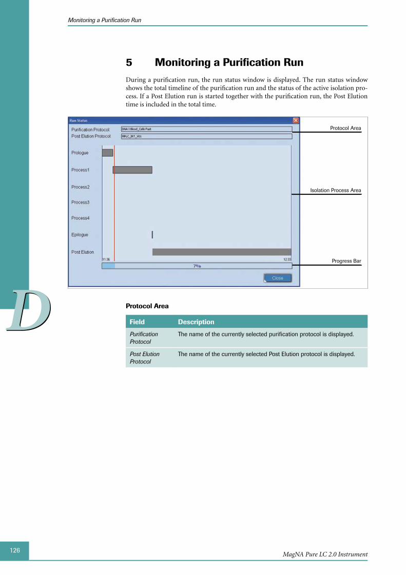
126
DD
MagNA Pure LC 2.0 Instrument
Monitoring a Purification Run
5 Monitoring a Purification RunDuring a purification run, the run status window is displayed. The run status window shows the total timeline of the purification run and the status of the active isolation pro-cess. If a Post Elution run is started together with the purification run, the Post Elution time is included in the total time.
Isolation Process Area
Progress Bar
Protocol Area
Protocol Area
Field Description
Purification Protocol
The name of the currently selected purification protocol is displayed.
Post Elution Protocol
The name of the currently selected Post Elution protocol is displayed.
127
DD
MagNA Pure LC 2.0 Software
Monitoring a Purification Run
The Isolation Process Area
Each active isolation process is displayed in the diagram as separate process bars. The x-axis of the diagram corresponds to the total process time: The position and length of the bars indicate the duration of the corresponding process and the sequence of the total process. Working periods of the process are shown as gray boxes, incubating periods as white boxes.
Some purification protocols perform ‘staggered processing’ to save time (e.g., Total NA Serum_Plasma_Blood). With staggered processing, two purification processes are run in parallel: One Processing Cartridge is processed, while the other one is incubating.
Staggered processing is only possible for two processes at the same time. In the case where 32 samples are processed, the first 16 samples are processed in two staggered processes. After completion of process 2, the following 16 samples are processed in two further staggered processes.
Process Description
Prologue During the prologue process, the surface of the Reagent/Sample Stage is checked for obstacles. Then, the isolation reagents are transferred from the Reagent Tubs into the wells of the Processing Cartridges. For every eight samples, an individual purification process is performed corresponding to one Processing Cartridge.
Process 1
...
Process 4
During the processing phase, the actual purification is performed, according to the selected purification protocol. For further details, see section Isolation Technology.
Epilogue During the Epilogue phase, the (optional) liquid waste discard is per-formed.
Post Elution During the Post Elution phase, pipetting of the (RT-)PCR reagents and samples is performed, according to the selected Post Elution protocol.
The start time and the expected completion time of the purification run are displayed in the bottom line of the Isolation Process Area (start time on the left and expected comple-tion time on the right).
Status and Total Time
The red vertical line in the Isolation Process Area shows the current state of the purifica-tion process.
The Progress Bar shows the current state of the whole process. The percentage value dis-played in the Progress Bar shows the completed process based on the whole process.
To close the Run Status window:
The purification run is not stopped if the Run Status window is closed.
Select Close. The Overview tab is displayed. The current run status is displayed in the Run Area, see section Run Area.
■
Once the ‘Run Status’ window is closed, you cannot access the sub-tabs: ‘Batch Results’, ‘Post Elution Edit’ and ‘Post Elution Results’ of the ‘Workplace’ tab during a purifica-tion run.
128
DD
MagNA Pure LC 2.0 Instrument
Monitoring a Purification Run
To open the Run Status window during a run:
Select the Run Status button in the Overview tab, see section Run Area. The Run Status window is displayed.
■
After completion of the purification run,
The ► Batch Results sub-tab is displayed, if no Post Elution run was selected, see section Batch Results.
The ► Post Elution Results sub-tab is displayed, if a Post Elution run was included. See section The Post Elution Edit (Sub-)Tab.
To edit and start a Post Elution run, see chapter Post Elution.
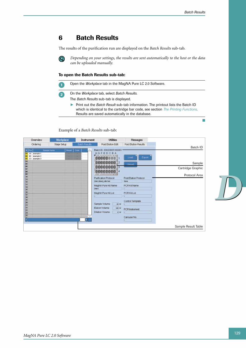
129
DD
MagNA Pure LC 2.0 Software
Batch Results
6 Batch ResultsThe results of the purification run are displayed on the Batch Results sub-tab.
Depending on your settings, the results are sent automatically to the host or the data can be uploaded manually.
To open the Batch Results sub-tab:
Open the Workplace tab in the MagNA Pure LC 2.0 Software.
On the Workplace tab, select Batch Results.
The Batch Results sub-tab is displayed.
Print out the ► Batch Result sub-tab information. The printout lists the Batch ID which is identical to the cartridge bar code, see section The Printing Functions. Results are saved automatically in the database.
■
Example of a Batch Results sub-tab:
Protocol Area
Batch ID
Sample
Cartridge Graphic
Sample Result Table
130
DD
MagNA Pure LC 2.0 Instrument
Batch Results
Sample Result Table and Sample Cartridge Graphic
The Sample Result Table displays the sample data entered in the Ordering tab and contains two additional columns:
Column Description
Result Status of each sample after completion of the purification run:
Pass/Green: The sample was purified correctly. ►Fail/Red: During purification of this sample, an error occurred. ►
Code Error Code for samples flagged as Fail, see section List of Error Codes.
The Sample Cartridge Graphic displays the result status. The wells are displayed color-coded according to the result status.
Green: the sample has passed ►
Red: the sample has failed ►
Gray: the sample was not loaded ►
Batch ID
The Batch ID is displayed above the Sample Cartridge Graphic.
Protocol Area
The protocol information is displayed according to your entries in the Ordering sub-tab, see sections Purification Protocol Area and Post Elution Protocol Area and PCR Instrument Area.
Buttons
Button Function
Load Loads previously saved purification results.
Export Save purification results as *.IRD file.
Upload Sends purification results to the host manually.
The button is only available if the option Manual is set, see section Setting up Parameters.
131
DD
MagNA Pure LC 2.0 Software
Batch Results
To load purification results:
Select Load. The Result Query window is displayed.
Define different search criteria for the purification results you want to load:
Batch ID: Enter the batch ID of a purification run. ►Sample Name: Enter a sample name from a purification result. ►Start Date: Open the dropdown menu and select the date of the purification run. ►MP Kit Lot: Enter the MagNA Pure LC Kit Lot of the purification run. ► It is not necessary to enter all or any search criteria.
Select Query, to start the search. The search results are listed below with the Batch ID, the Start Date Time and the User who started the purification run.
Select the purification result you want to load and confirm with the Select button.
The loaded purification result is displayed in the Batch Results sub-tab.
■
To export purification results:
Select Export. The Save as window is displayed.
Select the device or directory where the file should be saved.
Enter the name of the file and select Save.
■
To upload purification results:
Select Upload. The results are sent to the host.
The results are sent via file-sharing or HL7, depending on your settings in the Host Communication Area of the Setup Parameter sub-tab, see section Setting up Param-eters.
■

132
DD
MagNA Pure LC 2.0 Instrument
Managing User Access
Access Levels and Privileges
Managing User Access7 Access to the software is password restricted. Only users with authorized user names and passwords have access to the software.
MagNA Pure LC Standard Users, who can perform purification and Post Elution runs, must be registered by the Administrator first, before they can access the software.
7.1 Access Levels and Privileges
The Administrator
Controls software access and privileges of all Standard Users. ►
Registers the unique user name for each new Standard User. ►
Installs new protocols. ►
The Standard User
Can set up and run a nucleic acid preparation by selecting an existing protocol from ►a menu.
Can perform a Post Elution run. ►
Is defined by the Administrator. ►
The different access levels and privileges of MagNA Pure LC Users are in detail:
Software Tab / Button Standard Administrator
Overview X
Workplace Ordering X
Stage Setup X
Batch Results X
Post Elution Edit X
Post Elution Results X
Instrument Service X
Maintenance X
Utilities User Access X
Setup Parameter X
Messages X
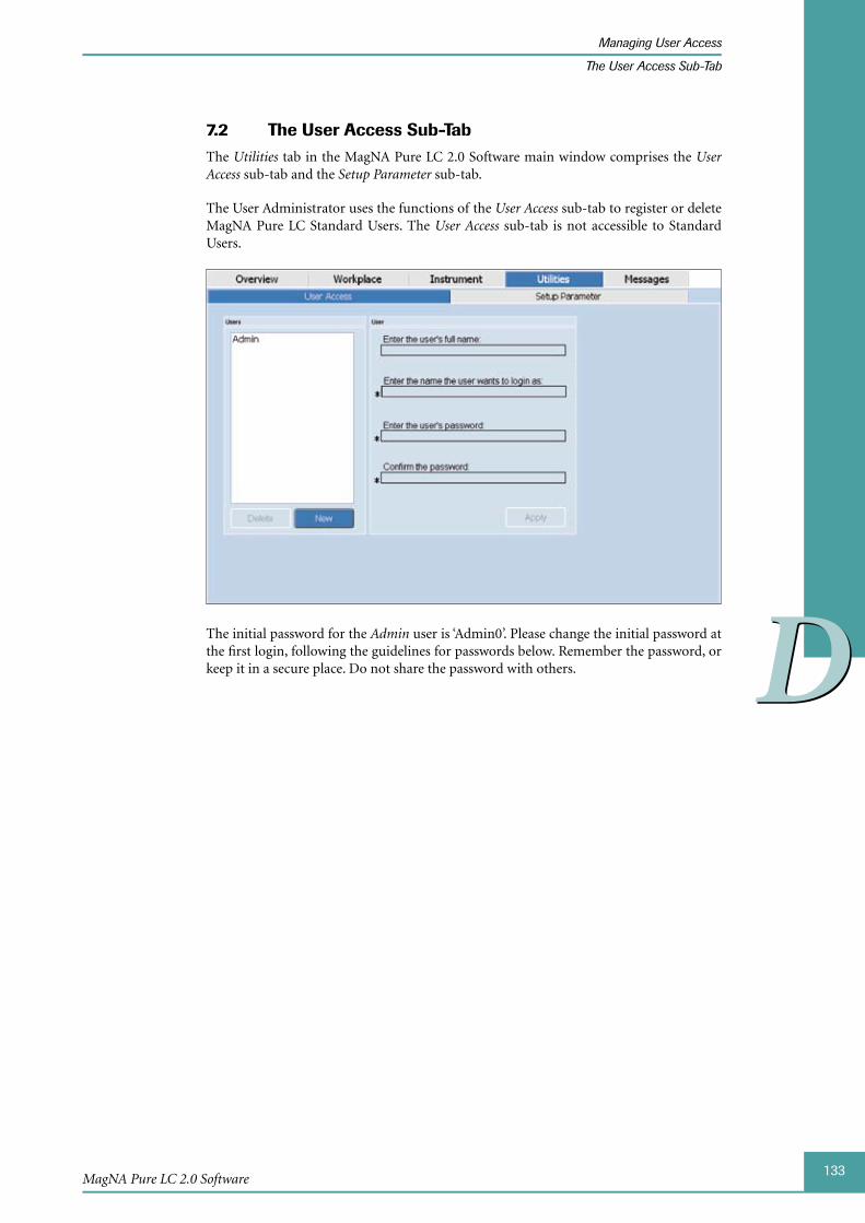
133
DD
MagNA Pure LC 2.0 Software
Managing User Access
The User Access Sub-Tab
The 7.2 User Access Sub-TabThe Utilities tab in the MagNA Pure LC 2.0 Software main window comprises the User Access sub-tab and the Setup Parameter sub-tab.
The User Administrator uses the functions of the User Access sub-tab to register or delete MagNA Pure LC Standard Users. The User Access sub-tab is not accessible to Standard Users.
The initial password for the Admin user is ‘Admin0’. Please change the initial password at the first login, following the guidelines for passwords below. Remember the password, or keep it in a secure place. Do not share the password with others.

134
DD
MagNA Pure LC 2.0 Instrument
Managing User Access
The User Access Sub-Tab
Users Area and User Area
Area Element Description
Users Users list Displays the registered users.
New button Adds a new user.
Delete button Deletes the selected user.
User Enter the user’s full name: field
Full name of the user.
Enter the name the user wants to login as: field
Name the user wants to log in as.
Spelling of the User Name must follow cer-tain rules to guarantee reliable function of the operating system and the MagNA Pure LC 2.0 Software:
A User Name must not be identical to any ►other user name.
A User Name may consist of up to 20 char- ►acters (either small or capital letters) with no spaces in between.
Instead of ‘space’ you may use ‘_’, e.g., firstname_lastname
A User Name must not contain the following ►characters:
“ / \ [ ] : ; = , + * | ? < > SPACE
A User Name must not consist solely of dots ►(.)
Enter the user’s password: field
Password of the user. The password must con-tain 6 characters, including a number.
Confirm the password: field
Password of the user.
Apply button Applies the content of the fields.
Fields that are marked with an asterisk (*) are necessary for creating a user.
For information on the Setup Parameter sub-tab see section Setting up Parameters.
135
DD
MagNA Pure LC 2.0 Software
Managing User Access
Operations Performed on the User Access Sub-Tab
Operations Performed on the User Access Sub-Tab7.3
To add a new user:
Select New in the Users Area.
Type the full name of the new User into the Enter the user’s full name field.
This is optional.
Type the name the new user wants to log in as, into the Enter the name the user wants to login as: field (e.g., user_1).
Type the password into the Enter the user’s password: field.
To confirm the password, retype it into the Confirm the password: field.
Confirm by selecting the Apply button. A pop-up window confirms that the new User was added successfully.
The user name of the new user is displayed in the Users list.
■
To delete a user account:
To delete a User account, select the respective User entry in the Users list.
Select the Delete button. A pop-up window confirms that the User was deleted successfully.
Deleting a User can not be undone once the ‘Delete’ button is touched.
■
To change a password:
To change only the password of a User without changing the User’s account, select the respective User entry in the Users list.
Type the new password into the Enter the user’s password: field.
Type the new password into the Confirm the password: field, to confirm it.
Confirm by selecting the Apply button. A pop-up window confirms the password was updated successfully
■
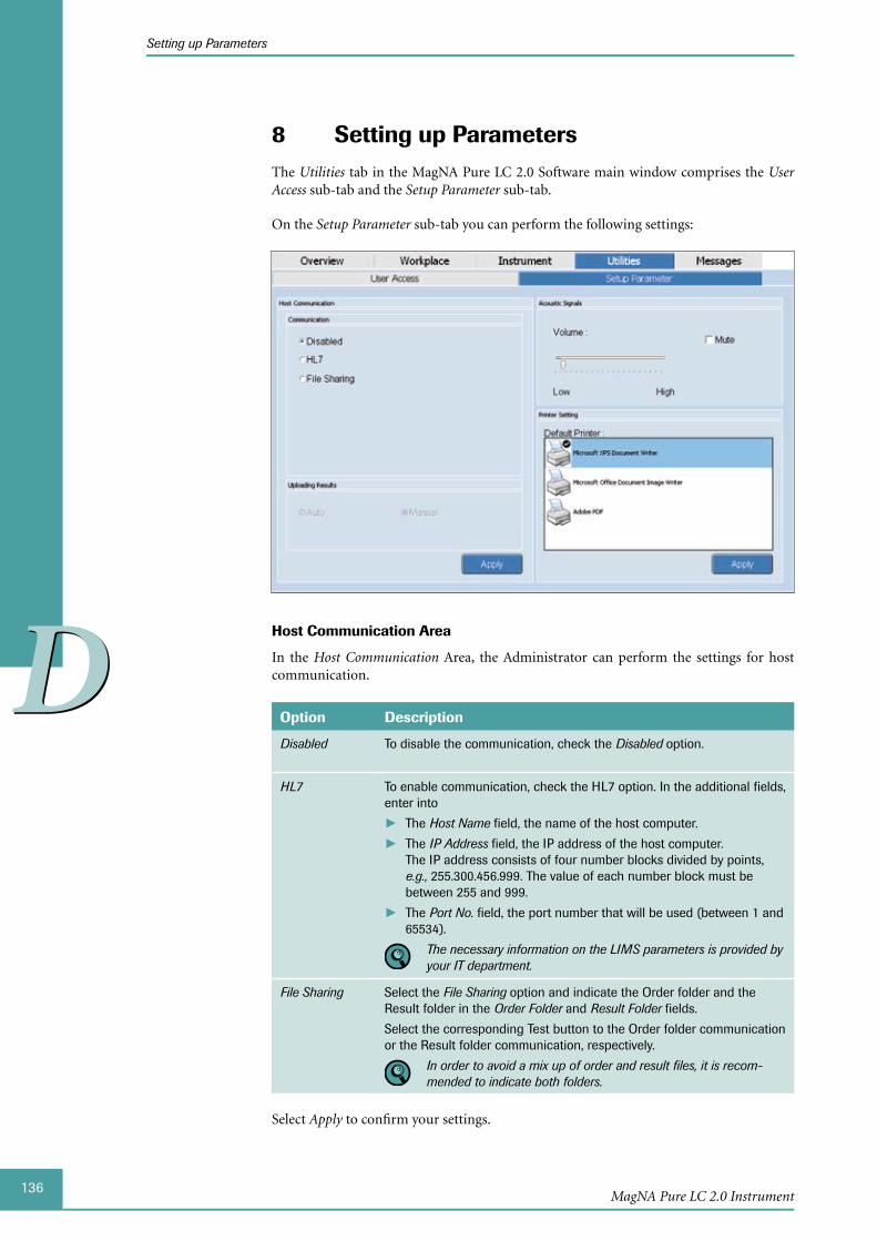
136
DD
MagNA Pure LC 2.0 Instrument
Setting up Parameters
8 Setting up ParametersThe Utilities tab in the MagNA Pure LC 2.0 Software main window comprises the User Access sub-tab and the Setup Parameter sub-tab.
On the Setup Parameter sub-tab you can perform the following settings:
Host Communication Area
In the Host Communication Area, the Administrator can perform the settings for host communication.
Option Description
Disabled To disable the communication, check the Disabled option.
HL7 To enable communication, check the HL7 option. In the additional fields, enter into
The ► Host Name field, the name of the host computer.
The ► IP Address field, the IP address of the host computer. The IP address consists of four number blocks divided by points, e.g., 255.300.456.999. The value of each number block must be between 255 and 999.
The ► Port No. field, the port number that will be used (between 1 and 65534).
The necessary information on the LIMS parameters is provided by your IT department.
File Sharing Select the File Sharing option and indicate the Order folder and the Result folder in the Order Folder and Result Folder fields.
Select the corresponding Test button to the Order folder communication or the Result folder communication, respectively.
In order to avoid a mix up of order and result files, it is recom-mended to indicate both folders.
Select Apply to confirm your settings.

137
DD
MagNA Pure LC 2.0 Software
Setting up Parameters
Uploading Results Area
Option Description
Auto If you want the Results to be uploaded automatically, check the Auto option in the Uploading Results Area.
Manual If you want to upload the Results manually, check the Manual option in the Uploading Results Area.
Select Apply to confirm your settings.
If automatic uploading of results is not successful, an error message is displayed. In this case the results can manually be uploaded to the host. The ‘Auto’ option must be se-lected again in the ‘Uploading Results’ Area, after an error.
Acoustic Signals Area
In the Acoustic Signals Area Standard users and the Administrator can adjust the sound source settings:
Element Description
Volume sliding controller
Move the Volume sliding controller to set the sound volume.
Mute option If you don’t want to hear any acoustic signals, check the Mute option.
Printer Setting Area
Field Description
Default Printer Select the printer in the list, which should become the default printer.
Select Apply to confirm your settings.
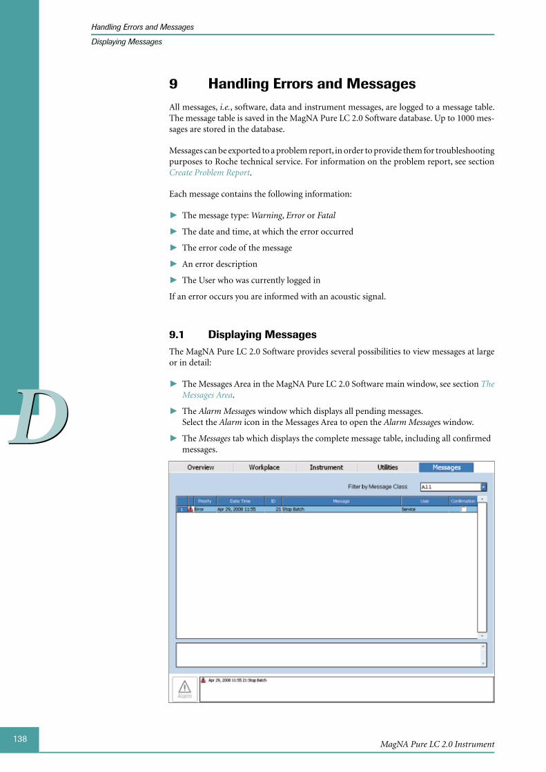
138
DD
MagNA Pure LC 2.0 Instrument
Handling Errors and Messages
Displaying Messages
Handling 9 Errors and MessagesAll messages, i.e., software, data and instrument messages, are logged to a message table. The message table is saved in the MagNA Pure LC 2.0 Software database. Up to 1000 mes-sages are stored in the database.
Messages can be exported to a problem report, in order to provide them for troubleshooting purposes to Roche technical service. For information on the problem report, see section Create Problem Report.
Each message contains the following information:
The ► message type: Warning, Error or Fatal
The date and time, at which the error occurred ►
The error code of the message ►
An error description ►
The User who was currently logged in ►
If an error occurs you are informed with an acoustic signal.
Displaying 9.1 MessagesThe MagNA Pure LC 2.0 Software provides several possibilities to view messages at large or in detail:
The Messages Area in the MagNA Pure LC 2.0 Software main window, see section ► The Messages Area.
The ► Alarm Messages window which displays all pending messages. Select the Alarm icon in the Messages Area to open the Alarm Messages window.
The ► Messages tab which displays the complete message table, including all confirmed messages.
139
DD
MagNA Pure LC 2.0 Software
Handling Errors and Messages
Confirming Messages
Both, the Alarm Messages window and the Messages tab, provide the messages in a table with the following columns:
Column Description
Priority Message type: Warning, Error or Fatal
Date Time Date and time, at which the error occurred
ID Error code
Message Error description
User User who was currently logged in
Confirmation Only in the Messages tab: Confirmation of the message
To filter messages by message type:
Select the dropdown list Filter by Message Class.
Select the corresponding message type.
The table displays only the messages with the selected type.
■
To display message details:
Select a message in the Messages Table.
The detailed information for the selected message is displayed in the text field below the Messages Table.
Select Print, on the Global Action Bar, to print the list of messages, see section The Printing Functions. To print detailed information regarding the selected message, select the Print button on the Global Action Bar and then the Print Screen / Print Messages button.
■
Confirming 9.2 MessagesWhen you have solved the problem the message indicates, or after for e.g., noting a warning, you can confirm the corresponding message.
To confirm a message:
Open the Alarm Messages window via the Alarm icon and select a message in the Messages Table.
Select Confirm.
The messages will be removed from the Messages Table in the Messages Area. ►The messages will be marked as confirmed in the ► Confirmation column of the Messages tab.
The ► Alarm icon in the Messages Area turns to Normal (Green).
Select the ‘Print’ button in the ‘Alarm Messages’ window, if you want to print the list of messages.
■

140
DD
MagNA Pure LC 2.0 Instrument
Data Transfer to and from the MagNA Pure LC 2.0 Instrument
Using LIMS for Data Transfer
10 Data Transfer to and from the MagNA Pure LC 2.0 Instrument
The results of a purification run and a Post Elution run can be saved and transferred to other Instruments or hosts.
LightCycler® Carousel-Based System or LightCycler® 480 Instrument ►
COBAS® TaqMan® 48 ►
Saved results may include the following information: Sample number, sample type, sam-ple name, sample comment, sample position, result value, result status and result flag.
Additionally you can install new or updated purification protocols and kits on the MagNA Pure LC 2.0 Instrument, see section Installing Purification Protocols and Kits.
Using 10.1 LIMS for Data TransferYou can use a Laboratory Information Management System (LIMS) for data transfer, if the MagNA Pure LC 2.0 Instrument is connected to the LIMS over a LAN connection.
The LIMS uses the HL7 transfer protocol. HL7 is a modern and well supported protocol for laboratory instruments.
You probably need to order a specific driver or connection module from your LIMS com-pany, or the person in charge of your LIMS system.
A detailed description of the LIMS communication is contained in a separate docu-ment, entitled ‘MagNA Pure LC 2.0 LIMS Programming Reference Manual’. For fur-ther details, contact your Roche representative.
10.2 Installing Purification Protocols and Kits Additional protocols are also available for download from
http://www.magnapure.com. Follow the download and installation instructions on this web site. Always save the downloaded protocol on to a newly formatted USB stick or CD/DVD.
If a new MagNA Pure LC Kit is available, an existing purification protocol is updated, or for an existing kit, an additional purification protocol is available, the respective purifica-tion protocol must be added to the MagNA Pure LC 2.0 Software via external data car-rier disks (e.g., USB stick and CD/DVD) during the start up of the MagNA Pure LC 2.0 Software.
Each purification protocol consists of two files: A blk-file and a plg-file. If a new kit or a feature of an existing kit is changed, a new kit-file must be installed, in addition to the blk- and plg-file. As a pre-requisite for successful installation, copy the files of one purification protocol and the correct ini-file on to a USB stick or CD/DVD. This is guaranteed when using protocol CDs available from Roche Applied Science; please contact your Roche rep-resentative.
141
DD
MagNA Pure LC 2.0 Software
Data Transfer to and from the MagNA Pure LC 2.0 Instrument
Installing Purification Protocols and Kits
To install a new purification protocol, or a new kit:
The MagNA Pure LC 2.0 Instrument must be shut down when starting the installa-tion process.
Put the USB stick or CD/DVD with the protocol and ini-file into the corresponding drive.
Start the MagNA Pure LC 2.0 Instrument.
The MagNA Pure LC 2.0 Software checks for updates automatically and performs them. The MagNA Pure LC 2.0 Software starts after the update.
■

142
DD
MagNA Pure LC 2.0 Instrument
Chapter E • Post Elution
144MagNA Pure LC 2.0 Instrument
Table of Contents
EE
E Post Elution
1 Introduction .....................................................................................................................................................145
2 Programming Post Elution .......................................................................................................................146
2.1 Post Elution Protocol Editor ..........................................................................................................................1462.2 MagNA Pure LC 2.0 System ........................................................................................................................1462.3 The Post Elution Edit (Sub-)Tab ..................................................................................................................147
3 Programming a New Post Elution Protocol ...................................................................................152
3.1 Selecting MagNA Pure LC Cooling Blocks ............................................................................................1523.2 Defining Type, Name and Initial Volume of Cooling Block Positions ...........................................1553.3 Programming Post Elution Pipetting Steps ............................................................................................161
4 Saving and Loading a Post Elution Protocol .................................................................................172
5 Editing a Post Elution Protocol .............................................................................................................173
5.1 Editing the Protocol Description Table.....................................................................................................1735.2 Editing Reaction Vessel Parameters .........................................................................................................176
6 Starting and Stopping a Post Elution Run or a Post Elution Simulation .......................177
7 Post Elution Results ....................................................................................................................................179
7.1 Post Elution Protocol Editor ..........................................................................................................................1817.2 MagNA Pure LC 2.0 System ........................................................................................................................182
8 Installing the Post Elution Protocol Editor on an External PC .............................................184
8.1 System Requirements ....................................................................................................................................1848.2 Installation ..........................................................................................................................................................184

145
EE
Post Elution
Introduction
Post Elution
Introduction1 In addition to its usage as an instrument for automated nucleic acid preparation, the MagNA Pure LC 2.0 System can be used as a programmable pipetting robot, for e.g., set-up of downstream PCR/RT-PCR reactions, using the previously isolated nucleic acids as template. Because the reaction set-up is performed after completion of the nucleic acid purification run, i.e., after elution of the isolated nucleic acids, this process is called Post Elution.
It is not necessary to perform a Post Elution run in direct combination with a purification run. A Post Elution run can also be performed as a single process, using previously iso-lated and stored nucleic acid samples. All pipetting steps performed by the MagNA Pure LC 2.0 Instrument are programmed by the user and stored as a Post Elution protocol file.
For programming Post Elution steps you can use the Post Elution function of the MagNA Pure LC 2.0 System or the Post Elution Protocol Editor on an external PC. See the following sections for a detailed description.
Programming Post Elution steps includes the following tasks:
Add template nucleic acid to (RT-)PCR master mixes in PCR reaction vessels ( ► e.g., LightCycler® Capillaries or 96-well PCR plates)
Further dilute isolated nucleic acid samples ►
Create dilutions series ►
Combine PCR reagents into PCR master mixes ►
Archive eluted samples into Reaction Tubes, for further storage ►
The following sections describe the Post Elution functions:
The functions of the ► Post Elution Edit (sub-)tab of the MagNA Pure LC 2.0 System or in the Post Elution Protocol Editor:
Program a new Post Elution protocol ►
Edit a Post Elution protocol ►
Save and load a pre-programmed Post Elution protocol ►
Start a Post Elution run ►
The function of the ► Simulation Results tab in the Post Elution Protocol Editor:
View Post Elution Results ►
The functions of the ► Post Elution Results sub-tab of the MagNA Pure LC 2.0 System:
View Post Elution Results ►
Save and upload Post Elution Results ►
Transfer Post Elution results via a SAM-file to the LightCycler® 4.1 Software or via ►a text file to the LightCycler® 480 Software.
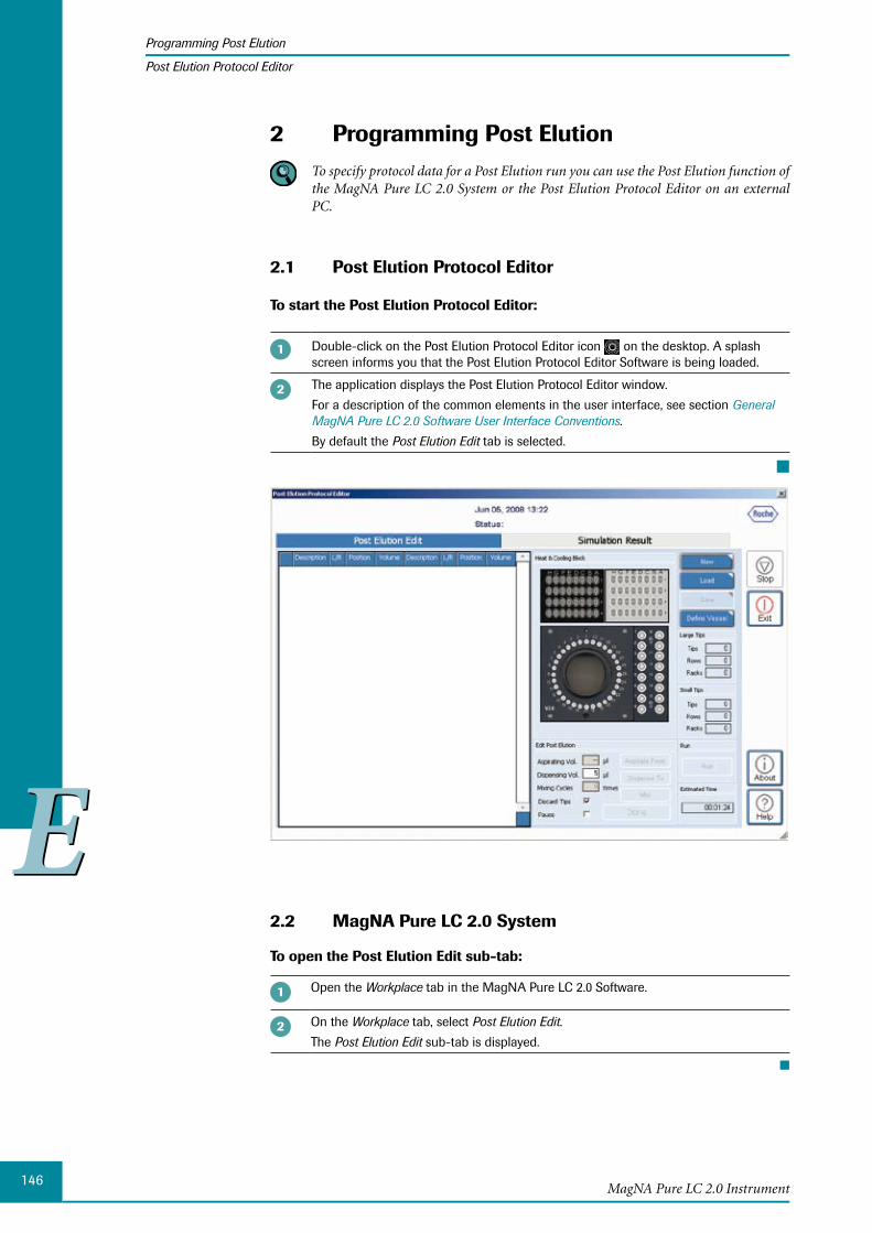
146
EE
MagNA Pure LC 2.0 Instrument
Programming Post Elution
Post Elution Protocol Editor
Programming Post Elution2 To specify protocol data for a Post Elution run you can use the Post Elution function of
the MagNA Pure LC 2.0 System or the Post Elution Protocol Editor on an external PC.
2.1 Post Elution Protocol Editor
To start the Post Elution Protocol Editor:
Double-click on the Post Elution Protocol Editor icon on the desktop. A splash screen informs you that the Post Elution Protocol Editor Software is being loaded.
The application displays the Post Elution Protocol Editor window.
For a description of the common elements in the user interface, see section General MagNA Pure LC 2.0 Software User Interface Conventions.
By default the Post Elution Edit tab is selected.
■
MagNA Pure LC 2.0 System2.2
To open the Post Elution Edit sub-tab:
Open the Workplace tab in the MagNA Pure LC 2.0 Software.
On the Workplace tab, select Post Elution Edit.
The Post Elution Edit sub-tab is displayed.
■

147
EE
Post Elution
Programming Post Elution
The Post Elution Edit (Sub-)Tab
The 2.3 Post Elution Edit (Sub-)TabThe following section describes the Post Elution (sub-)tab. The functions of this tab are identical in the MagNA Pure LC 2.0 System and in the Post Elution Protocol Editor.
Some functions are only accessible if a Post Elution protocol is loaded.
Protocol Description Table
In the Protocol Description Table, the programmed Aspirate-Dispense Sets of the Post Elution protocol are listed.
During the execution of the protocol, the steps are processed from top to bottom.
Column Description
Description Name of the sample/reagent container (e.g., Sample Cartridge or LC Sample Carousel Cooling Block).
L/R Only if small Cooling Blocks are used: Indicates whether a Cooling Block is positioned on the left or right half of Cooling Unit 2.
Position Position of the reaction vessel in the corresponding container (Sample Cartridge or Cooling Block).
Volume Volume of sample/reagent that is pipetted from or to the corresponding reaction vessel.
It is possible to change the column width: Select a column divider line in the column title area and drag it to a new position.

148
EE
MagNA Pure LC 2.0 Instrument
Programming Post Elution
The Post Elution Edit (Sub-)Tab
The columns of the Protocol Description Table are listed twice:
The left column set corresponds to the ► Aspirate From position.
The right column set corresponds to the ► Dispense To position.
Each Aspirate-Dispense Set consists of at least two rows:
A status line displaying general information on mixing and tip discard status and ►
A parameter line displaying the parameters of the Aspirate-Dispense Set ( ► Aspirate From position, Dispense To position, Dispensing Volume), or Mixing Step (Mixing Vol-ume), respectively.
Type and status of Aspirate-Dispense Sets are indicated by the color of the status line:
Column Description
Green Common Aspirate-Dispense Set, no error.
Red Volume error due to a too low initial volume, or because of exceeding the maximum capacity of a reaction vessel.
Yellow Mixing step
White Pausing step
Heating & Cooling Block Area
Element Description
Storage Cartridge
Graphical display of the Storage Cartridge within Cooling Unit 1.
Samples processed during a previous purification run, or otherwise speci-fied, are shown in yellow (shaded yellow, if a volume is to be dispensed from this position during Post Elution).
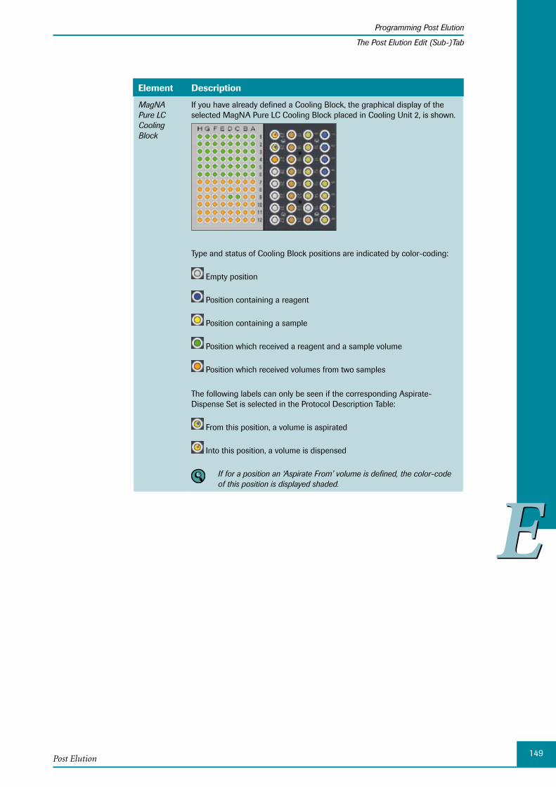
149
EE
Post Elution
Programming Post Elution
The Post Elution Edit (Sub-)Tab
Element Description
MagNA Pure LC Cooling Block
If you have already defined a Cooling Block, the graphical display of the selected MagNA Pure LC Cooling Block placed in Cooling Unit 2, is shown.
Type and status of Cooling Block positions are indicated by color-coding:
Empty position
Position containing a reagent
Position containing a sample
Position which received a reagent and a sample volume
Position which received volumes from two samples
The following labels can only be seen if the corresponding Aspirate- Dispense Set is selected in the Protocol Description Table:
From this position, a volume is aspirated
Into this position, a volume is dispensed
If for a position an ‘Aspirate From’ volume is defined, the color-code of this position is displayed shaded.

150
EE
MagNA Pure LC 2.0 Instrument
Programming Post Elution
The Post Elution Edit (Sub-)Tab
Edit Post Elution Area
The buttons and fields of the Edit Post Elution Area are used for programming the Post Elution pipetting steps.
Field/Button
Description
Aspirating Vol.
Is automatically filled with the Dispensing Volume value.
Dispensing Vol.
Volume which should be dispensed from a reaction vessel (allowed range: a whole number between 5 and 100 µl).
Mixing Cycles
When programming a mixing step enter the number of mixing cycles (maxi-mum number is 15; optimal number is 10).
Discard Tips If this option is checked, the Instrument discards the Reaction Tips after completion of the pipetting step.
When performing a multi-dispensing step, if the ‘Discard Tips’ option is activated, Reaction Tips are discarded after every single pipetting step. If ‘Discard Tips’ is not activated, Reaction Tips are discarded automatically after the last pipetting step.
Pause If this option is checked, the Instrument pauses the Post Elution run after completion of the current Aspirate-Dispense Set.
This is useful if you must place or exchange a reagent or disposable plastic (e.g., additional Reaction Tips) on the Reagent/Sample Stage after comple-tion of a defined Aspirate-Dispense Set.
For instance, if you want to perform RT-PCR reactions, you first may use the Post Elution function to set-up the Reverse Transcription (RT) reactions. After pipetting all isolation reagents and samples for the RT, you pause the Post Elution run by programming a PAUSE step and place the reac-tion vessels into a suitable heat block for performing the RT reaction. After completion of the RT reaction, you place the Reactions Vessels back into the MagNA Pure LC 2.0 Instrument and resume the Post Elution run for set-up of PCR reactions.
If you use this function, the results will be marked tentatively as ‘Failed’. This is because the Instrument does not know how long the Post Elution protocol was paused and so the pipetting accuracy and results can not be guaranteed because of possible evaporation of the reagents.
Aspirate From
To define the Aspirate From position
Dispense To To define the Dispense To position
Mix To define a mixing step, see section Programming a Mixing Step.
Done To confirm the programming of a Post Elution pipetting step.

151
EE
Post Elution
Programming Post Elution
The Post Elution Edit (Sub-)Tab
Buttons
Button Description
New To program a new Post Elution protocol, see section Programming a New Post Elution Protocol.
Load To load a previously saved Post Elution protocol file (*.pep).
The MagNA Pure LC 2.0 Software stores Post Elution protocol information in a single file (*.pep). Post Elution protocols can be pro-grammed using the standalone Post Elution Protocol Editor.
Save the protocol file (*.pep) to a memory stick. Insert the stick into the MagNA Pure LC 2.0 Instrument and load the file by selecting the ‘Load’ button in the ‘Post Elution Edit’ sub-tab.
To use the Post Elution protocol in the ‘Ordering’ sub-tab, the file must be saved to the Instrument first with the ‘Save’ button.
Save To save a new or modified Post Elution protocol.
Define Vessel
If no vessel is selected: The ► Post Elution Define Name / Set Volume win-dow is displayed. You can define type, name and initial volume of the reaction vessel positions in the Cooling Block. For details, see section Defining Type, Name and Initial Volume of Cooling Block Positions.
If one or more vessels are selected in the Storage Cartridge or in the ►Cooling Block: The Define Vessel window is displayed. You can de-fine type, name and initial volume, see section Editing Reaction Vessel Parameters.
Control and Information Areas
Area Function
Large Tips The number of Large Reaction Tips required is displayed.
Large Reaction Tips are used for mixing steps only.
Small Tips The number of Small Reaction Tips required is displayed.
Run The Run button starts the Post Elution run.
Estimated Time
The Estimated Time needed for completion of the Post Elution run is displayed.
Once a Post Elution protocol has been run, if the protocol is loaded again, the Measured Time instead of the Estimated Time will be displayed in the Estimated Time area.
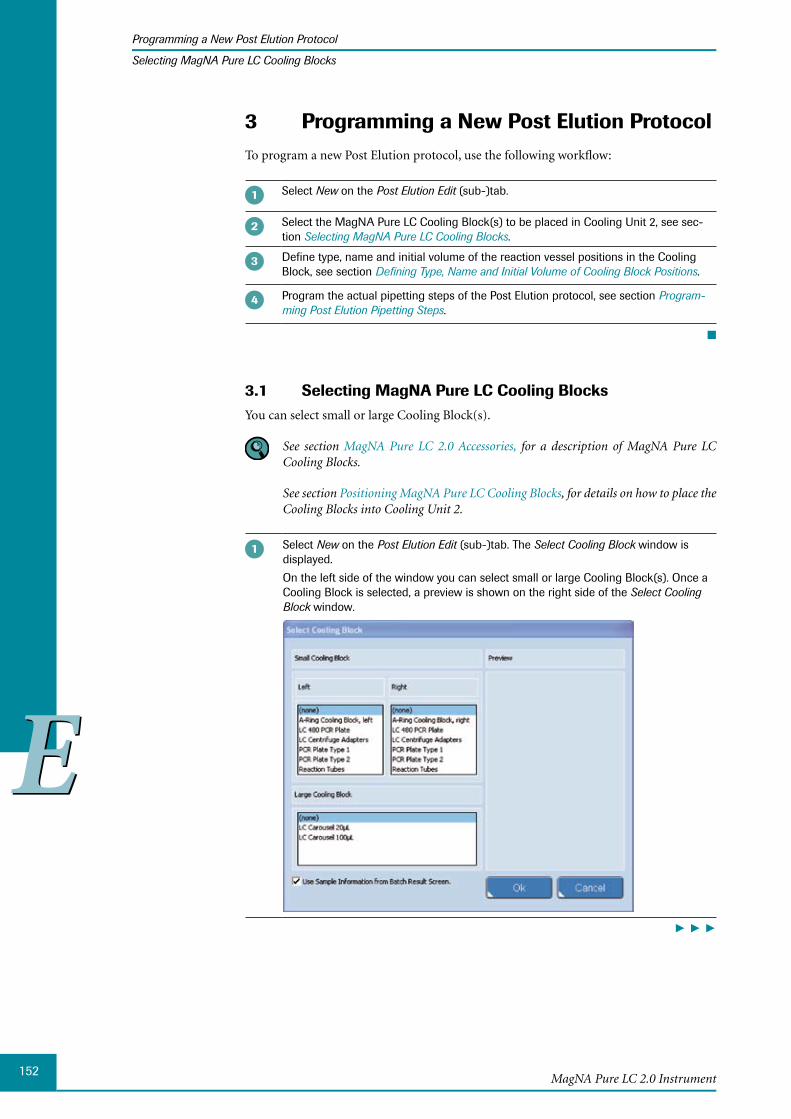
152
EE
MagNA Pure LC 2.0 Instrument
Programming a New Post Elution Protocol
Selecting MagNA Pure LC Cooling Blocks
3 Programming a New Post Elution ProtocolTo program a new Post Elution protocol, use the following workflow:
Select New on the Post Elution Edit (sub-)tab.
Select the MagNA Pure LC Cooling Block(s) to be placed in Cooling Unit 2, see sec-tion Selecting MagNA Pure LC Cooling Blocks.
Define type, name and initial volume of the reaction vessel positions in the Cooling Block, see section Defining Type, Name and Initial Volume of Cooling Block Positions.
Program the actual pipetting steps of the Post Elution protocol, see section Program-ming Post Elution Pipetting Steps.
■
Selecting 3.1 MagNA Pure LC Cooling BlocksYou can select small or large Cooling Block(s).
See section MagNA Pure LC 2.0 Accessories, for a description of MagNA Pure LC Cooling Blocks.
See section Positioning MagNA Pure LC Cooling Blocks, for details on how to place the Cooling Blocks into Cooling Unit 2.
Select New on the Post Elution Edit (sub-)tab. The Select Cooling Block window is displayed.
On the left side of the window you can select small or large Cooling Block(s). Once a Cooling Block is selected, a preview is shown on the right side of the Select Cooling Block window.
► ► ►
153
EE
Post Elution
Programming a New Post Elution Protocol
Selecting MagNA Pure LC Cooling Blocks
In the Select Cooling Block window, select the MagNA Pure LC Cooling Block(s) to be placed into the large Cooling Unit 2. Select the appropriate Cooling Block by selecting its name.
You can select either two small Cooling Blocks or one large Cooling Block.
To select small Cooling Blocks: ►Select a Cooling Block for both the left and right half of Cooling Unit 2. Select the small MagNA Pure LC Cooling Blocks from the Left/Right list in the Small Cooling Block area.
Small Cooling Blocks you can choose from are:
A-Ring Cooling Block, left and A-Ring Cooling Block, right: MagNA Pure LC ►Cooling Block, A-Ring
LC 480 PCR Plate: MagNA Pure LC Cooling Block, 96-well PCR Plate and the ►MagNA Pure LC LightCycler® 480 Plate Adapter
LC Centrifuge Adapters: MagNA Pure LC Cooling Block, LC Centrifuge Adapt- ►ers
PCR Plate, Type 1 and/or PCR Plate, Type 2: MagNA Pure LC Cooling Block, ►96-well PCR Plate
Reaction Tubes: MagNA Pure LC Cooling Block, Reaction Tubes ►For more Information on the different Cooling Blocks see section Additional MagNA Pure LC Cooling Blocks.
Although the MagNA Pure LC Cooling Block, A-Ring, physically occupies the complete Cooling Unit 2, it is selected in the ‘Small Cooling Block’ area. The left and right half of the Cooling Block, corresponding to A-Ring A and A-Ring B, can be selected individually as a Small Cooling Block.
To select a large Cooling Block: ►Select a large MagNA Pure LC Cooling Block from the list in the Large Cooling Block area.
Large Cooling Blocks you can choose from are:
LC Carousel 20 µl: MagNA Pure LC Cooling Block, LC Sample Carousel ►LC Carousel 100 µl: MagNA Pure LC Cooling Block, LC Sample Carousel ►
MagNA Pure LC 2.0 System only:
If the option Use Sample Information from Batch Result Screen is checked, the sample information and Batch ID from the Batch Results sub-tab are transferred to the Post Elution (this is checked by default).
If you don’t want to use the sample information and Batch ID from the Batch Results sub-tab, uncheck the option Use Sample Information from Batch Result Screen.
If you want to use a previously saved Batch Result, then it can be loaded by using the Search Query window and then transferred to the Post Elution Edit sub-tab.
Select OK, to confirm the selection of the Cooling Block(s).
You can select and confirm the selection in one step, by selecting the respective Cooling Block name twice.
► ► ►

154
EE
MagNA Pure LC 2.0 Instrument
Programming a New Post Elution Protocol
Selecting MagNA Pure LC Cooling Blocks
In case, you have selected the A-Ring Cooling Block, you must enter the A-Ring bar code(s) to ensure proper sample tracking from the primary sample to the set-up of PCR reactions by the COBAS® AmpliCor® Instrument. See section A-Ring Cooling Blocks for further information.
■
After a Cooling Block has been selected, the Post Elution Define Name / Set Volume window is displayed, see section Defining Type, Name and Initial Volume of Cooling Block Posi-tions.
A-Ring Cooling Blocks
The MagNA Pure LC 2.0 Instrument can be used as a front-end sample preparation sys-tem, in combination with COBAS® AmpliCor® Instrument tests.
The MagNA Pure LC Cooling Block, A-Ring, enables the automatic set-up of PCR reac-tions by the COBAS® AmpliCor® Instrument, by combining eluted samples and PCR reagents of the COBAS® AmpliCor® Instrument tests directly within the reaction vessels of COBAS® AmpliCor® A-Rings by Post Elution pipetting.
MagNA Pure LC 2.0 System is intended for general laboratory use only. It was neither developed nor validated by the manufacturer for any kind of in-vitro diagnostic application. Any use of the MagNA Pure LC 2.0 System as a front-end sample preparation system for in-vitro diagnostic test systems (e.g., COBAS® AmpliCor® Instrument tests) is in the sole responsibility of the user. The validation of the combination of MagNA Pure LC nucleic acid isolation and in-vitro diagnostic testing must be done by the user, following the relevant national rules. Thus, the A-Ring workflow relates only to the software handling in case the MagNA Pure LC 2.0 Instrument is used in combination with COBAS® AmpliCor® A-Rings and the respective MagNA Pure LC Cooling Block. It does not include reagents, purification protocols, or application-related working instructions specific for COBAS® AmpliCor® Instrument sample preparation.
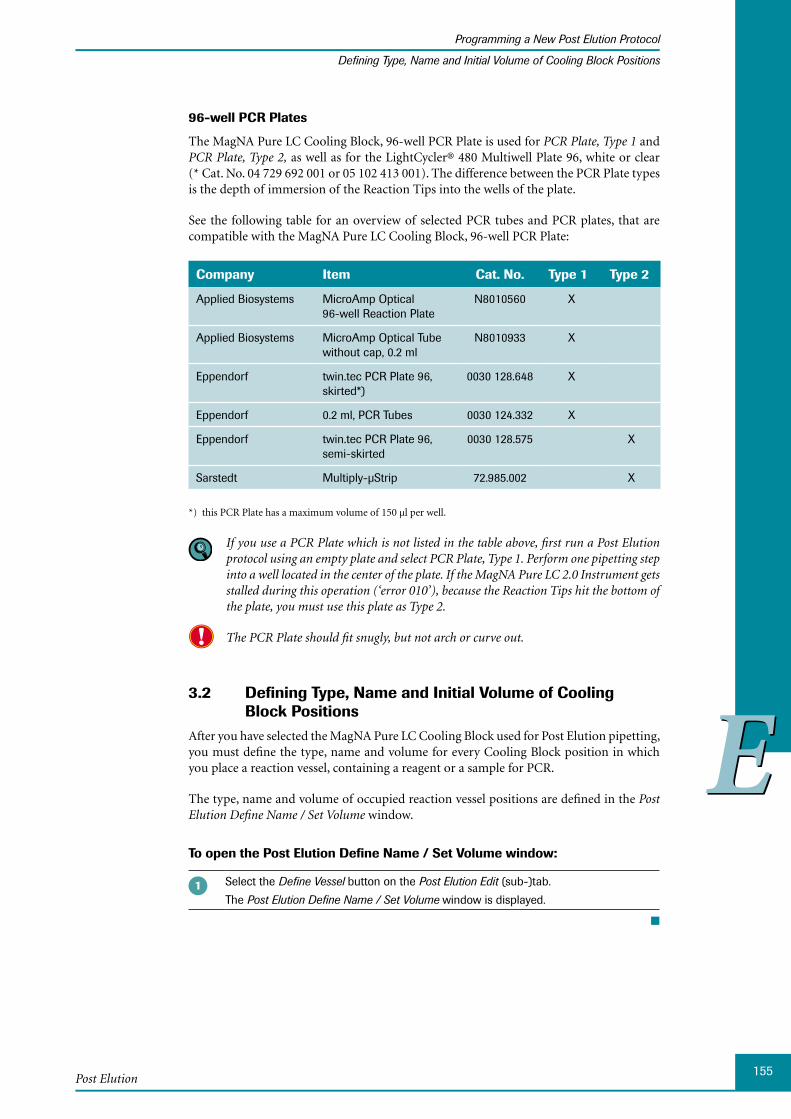
155
EE
Post Elution
Programming a New Post Elution Protocol
Defining Type, Name and Initial Volume of Cooling Block Positions
96-well PCR Plates
The MagNA Pure LC Cooling Block, 96-well PCR Plate is used for PCR Plate, Type 1 and PCR Plate, Type 2, as well as for the LightCycler® 480 Multiwell Plate 96, white or clear (* Cat. No. 04 729 692 001 or 05 102 413 001). The difference between the PCR Plate types is the depth of immersion of the Reaction Tips into the wells of the plate.
See the following table for an overview of selected PCR tubes and PCR plates, that are compatible with the MagNA Pure LC Cooling Block, 96-well PCR Plate:
Company Item Cat. No. Type 1 Type 2
Applied Biosystems MicroAmp Optical 96-well Reaction Plate
N8010560 X
Applied Biosystems MicroAmp Optical Tube without cap, 0.2 ml
N8010933 X
Eppendorf twin.tec PCR Plate 96, skirted*)
0030 128.648 X
Eppendorf 0.2 ml, PCR Tubes 0030 124.332 X
Eppendorf twin.tec PCR Plate 96, semi-skirted
0030 128.575 X
Sarstedt Multiply-µStrip 72.985.002 X
*) this PCR Plate has a maximum volume of 150 µl per well.
If you use a PCR Plate which is not listed in the table above, first run a Post Elution protocol using an empty plate and select PCR Plate, Type 1. Perform one pipetting step into a well located in the center of the plate. If the MagNA Pure LC 2.0 Instrument gets stalled during this operation (‘error 010’), because the Reaction Tips hit the bottom of the plate, you must use this plate as Type 2.
The PCR Plate should fit snugly, but not arch or curve out.
3.2 Defining Type, Name and Initial Volume of Cooling Block Positions
After you have selected the MagNA Pure LC Cooling Block used for Post Elution pipetting, you must define the type, name and volume for every Cooling Block position in which you place a reaction vessel, containing a reagent or a sample for PCR.
The type, name and volume of occupied reaction vessel positions are defined in the Post Elution Define Name / Set Volume window.
To open the Post Elution Define Name / Set Volume window:
Select the Define Vessel button on the Post Elution Edit (sub-)tab.
The Post Elution Define Name / Set Volume window is displayed.
■

156
EE
MagNA Pure LC 2.0 Instrument
Programming a New Post Elution Protocol
Defining Type, Name and Initial Volume of Cooling Block Positions
The window is displayed automatically, when
You confirm the selection of Cooling Block(s) ►
You program a new Post Elution protocol or ►
You load an existing Post Elution protocol ►
To edit type, name or initial volume settings of Cooling Block positions later, see sec-tion Editing Reaction Vessel Parameters.
The Post Elution Define Name / Set Volume Window
The Post Elution Define Name / Set Volume window resembles a spreadsheet table in ap-pearance. Fields which can be modified by the user are white, while informative fields filled by the software are displayed in gray.
The following table columns are filled by default and cannot be modified:
Column Description
Block Name Name of the selected Cooling Block (LC Carousel (20 µl or 100 µl), LC Centrifuge Adapters, Reaction Tubes, PCR Plate (Type 1 or Type 2, LC 480 PCR Plate), A-Ring Cooling Block left or right.
L/R Position (left/right) of the Cooling Block in Cooling Unit 2 (only valid for small Cooling Blocks).
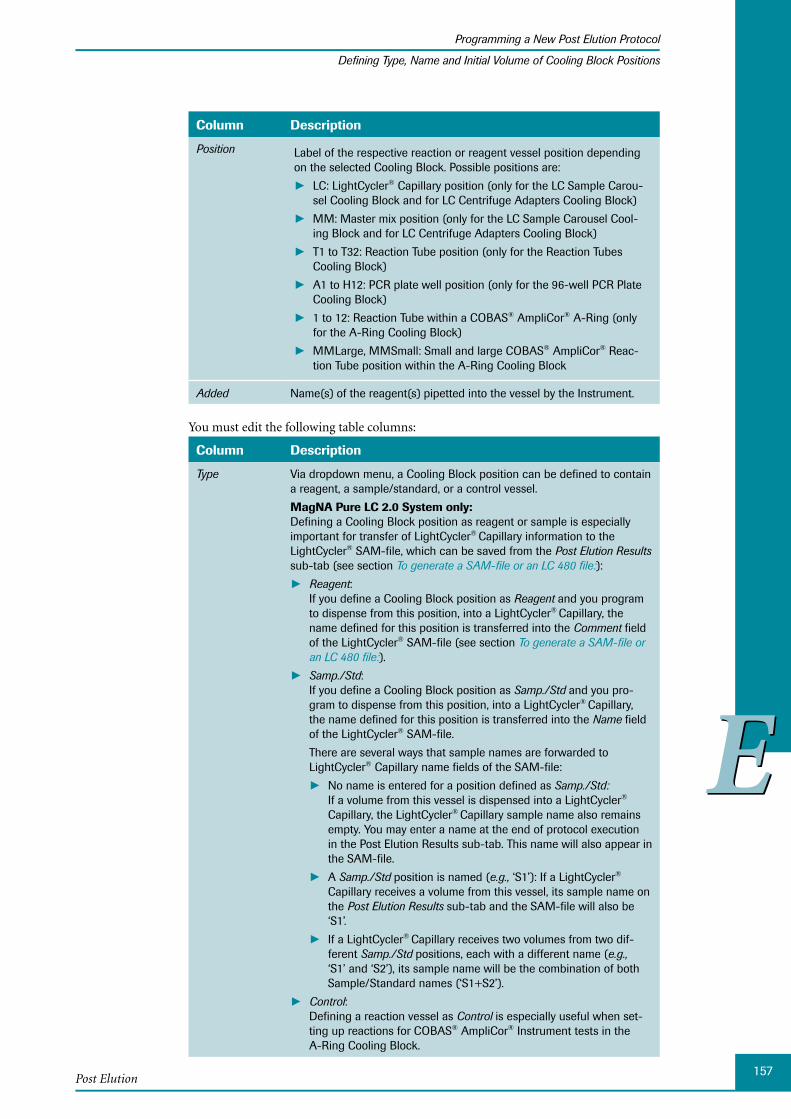
157
EE
Post Elution
Programming a New Post Elution Protocol
Defining Type, Name and Initial Volume of Cooling Block Positions
Column Description
Position Label of the respective reaction or reagent vessel position depending on the selected Cooling Block. Possible positions are:
LC: LightCycler ► ® Capillary position (only for the LC Sample Carou-sel Cooling Block and for LC Centrifuge Adapters Cooling Block)
MM: Master mix position (only for the LC Sample Carousel Cool- ►ing Block and for LC Centrifuge Adapters Cooling Block)
T1 to T32: Reaction Tube position (only for the Reaction Tubes ►Cooling Block)
A1 to H12: PCR plate well position (only for the 96-well PCR Plate ►Cooling Block)
1 to 12: Reaction Tube within a COBAS ► ® AmpliCor® A-Ring (only for the A-Ring Cooling Block)
MMLarge, MMSmall: Small and large COBAS ► ® AmpliCor® Reac-tion Tube position within the A-Ring Cooling Block
Added Name(s) of the reagent(s) pipetted into the vessel by the Instrument.
You must edit the following table columns:
Column Description
Type Via dropdown menu, a Cooling Block position can be defined to contain a reagent, a sample/standard, or a control vessel.
MagNA Pure LC 2.0 System only: Defining a Cooling Block position as reagent or sample is especially important for transfer of LightCycler® Capillary information to the LightCycler® SAM-file, which can be saved from the Post Elution Results sub-tab (see section To generate a SAM-file or an LC 480 file:):
Reagent ► : If you define a Cooling Block position as Reagent and you program to dispense from this position, into a LightCycler® Capillary, the name defined for this position is transferred into the Comment field of the LightCycler® SAM-file (see section To generate a SAM-file or an LC 480 file:).
Samp./Std ► : If you define a Cooling Block position as Samp./Std and you pro-gram to dispense from this position, into a LightCycler® Capillary, the name defined for this position is transferred into the Name field of the LightCycler® SAM-file.
There are several ways that sample names are forwarded to LightCycler® Capillary name fields of the SAM-file:
No name is entered for a position defined as ► Samp./Std: If a volume from this vessel is dispensed into a LightCycler®
Capillary, the LightCycler® Capillary sample name also remains empty. You may enter a name at the end of protocol execution in the Post Elution Results sub-tab. This name will also appear in the SAM-file.
A ► Samp./Std position is named (e.g., ‘S1’): If a LightCycler®
Capillary receives a volume from this vessel, its sample name on the Post Elution Results sub-tab and the SAM-file will also be ‘S1’.
If a LightCycler ► ® Capillary receives two volumes from two dif-ferent Samp./Std positions, each with a different name (e.g., ‘S1’ and ‘S2’), its sample name will be the combination of both Sample/Standard names (‘S1+S2’).
Control ► : Defining a reaction vessel as Control is especially useful when set-ting up reactions for COBAS® AmpliCor® Instrument tests in the A-Ring Cooling Block.
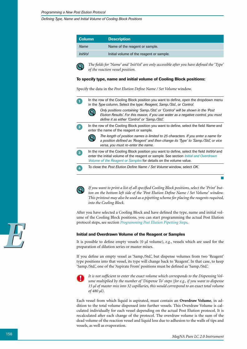
158
EE
MagNA Pure LC 2.0 Instrument
Programming a New Post Elution Protocol
Defining Type, Name and Initial Volume of Cooling Block Positions
Column Description
Name Name of the reagent or sample.
InitVol Initial volume of the reagent or sample.
The fields for ‘Name’ and ‘InitVol’ are only accessible after you have defined the ‘Type’ of the reaction vessel position.
To specify type, name and initial volume of Cooling Block positions:
Specify the data in the Post Elution Define Name / Set Volume window.
In the row of the Cooling Block position you want to define, open the dropdown menu in the Type column. Select the type: Reagent, Samp./Std., or Control.
Only positions containing ‘Samp./Std.’ or ‘Control’ will be shown in the ‘Post Elution Results’. For this reason, if you use water as a negative control, you must define it as either ‘Control’ or ‘Samp./Std.’.
In the row of the Cooling Block position you want to define, select the field Name and enter the name of the reagent or sample.
The length of position names is limited to 25 characters. If you enter a name for a position defined as ‘Reagent’ and then change its ‘Type’ to ‘Samp./Std.’, or vice versa, you must re-enter the name.
In the row of the Cooling Block position you want to define, select the field InitVol and enter the initial volume of the reagent or sample. See section Initial and Overdrawn Volume of the Reagent or Samples for details on the volume value.
To close the Post Elution Define Name / Set Volume window, select OK.
■
If you want to print a list of all specified Cooling Block positions, select the ‘Print’ but-ton on the bottom left side of the ‘Post Elution Define Name / Set Volume’ window. This printout may also be used as a pipetting scheme for placing the reagents required, into the Cooling Block.
After you have selected a Cooling Block and have defined the type, name and initial vol-ume of the Cooling Block positions, you can start programming the actual Post Elution protocol steps, see section Programming Post Elution Pipetting Steps.
Initial and Overdrawn Volume of the Reagent or Samples
It is possible to define empty vessels (0 µl volume), e.g., vessels which are used for the preparation of dilution series or master mixes.
If you define an empty vessel as ‘Samp./Std.’, but dispense volumes from two ‘Reagent’ type positions into that vessel, its type will change back to ‘Reagent’. In that case, to keep ‘Samp./Std.’, one of the ‘Aspirate From’ positions must be defined as ‘Samp./Std.’.
It is not sufficient to enter the exact volume which corresponds to the Dispensing Vol-ume multiplied by the number of ‘Dispense To’ steps (for e.g., if you want to dispense 15 µl of master mix into 32 capillaries, this would correspond to an exact total volume of 480 µl).
Each vessel from which liquid is aspirated, must contain an Overdraw Volume, in ad-dition to the total volume dispensed into further vessels. This Overdraw Volume is cal-culated individually for each vessel depending on the actual Post Elution protocol. It is recalculated after each change of the protocol. The overdraw volume is the sum of the dead volume of the reaction vessel and liquid loss due to adhesion to the walls of tips and vessels, as well as evaporation.
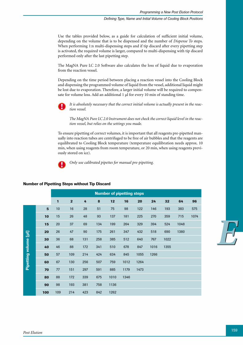
159
EE
Post Elution
Programming a New Post Elution Protocol
Defining Type, Name and Initial Volume of Cooling Block Positions
Use the tables provided below, as a guide for calculation of sufficient initial volume, depending on the volume that is to be dispensed and the number of Dispense To steps. When performing 1:n multi-dispensing steps and if tip discard after every pipetting step is activated, the required volume is larger, compared to multi-dispensing with tip discard performed only after the last pipetting step.
The MagNA Pure LC 2.0 Software also calculates the loss of liquid due to evaporation from the reaction vessel.
Depending on the time period between placing a reaction vessel into the Cooling Block and dispensing the programmed volume of liquid from the vessel, additional liquid might be lost due to evaporation. Therefore, a larger initial volume will be required to compen-sate for volume loss. Add an additional 1 µl for every 10 min of standing time.
It is absolutely necessary that the correct initial volume is actually present in the reac-tion vessel.
The MagNA Pure LC 2.0 Instrument does not check the correct liquid level in the reac-tion vessel, but relies on the settings you made.
To ensure pipetting of correct volumes, it is important that all reagents pre-pipetted man-ually into reaction tubes are centrifuged to be free of air bubbles and that the reagents are equilibrated to Cooling Block temperature (temperature equilibration needs approx. 10 min, when using reagents from room temperature, or 20 min, when using reagents previ-ously stored on ice).
Only use calibrated pipettes for manual pre-pipetting.
Number of Pipetting Steps without Tip Discard
Number of pipetting steps
1 2 4 8 12 16 20 24 32 64 96
Pip
etti
ng v
olum
e [µ
l]
5 10 16 28 51 75 98 122 146 193 383 575
10 15 26 48 93 137 181 225 270 359 715 1074
15 20 37 69 134 199 264 329 394 524 1048
20 26 47 90 175 261 347 432 518 690 1380
30 36 68 131 258 385 512 640 767 1022
40 46 88 172 341 510 678 847 1016 1355
50 57 109 214 424 634 845 1055 1266
60 67 130 256 507 759 1012 1264
70 77 151 297 591 885 1179 1473
80 88 172 339 675 1010 1346
90 98 193 381 758 1136
100 109 214 423 842 1262
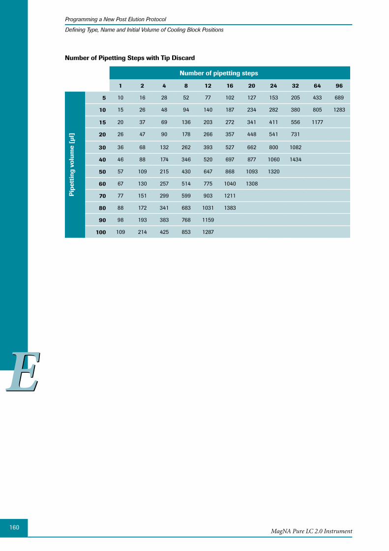
160
EE
MagNA Pure LC 2.0 Instrument
Programming a New Post Elution Protocol
Defining Type, Name and Initial Volume of Cooling Block Positions
Number of Pipetting Steps with Tip Discard
Number of pipetting steps
1 2 4 8 12 16 20 24 32 64 96
Pip
etti
ng v
olum
e [µ
l]
5 10 16 28 52 77 102 127 153 205 433 689
10 15 26 48 94 140 187 234 282 380 805 1283
15 20 37 69 136 203 272 341 411 556 1177
20 26 47 90 178 266 357 448 541 731
30 36 68 132 262 393 527 662 800 1082
40 46 88 174 346 520 697 877 1060 1434
50 57 109 215 430 647 868 1093 1320
60 67 130 257 514 775 1040 1308
70 77 151 299 599 903 1211
80 88 172 341 683 1031 1383
90 98 193 383 768 1159
100 109 214 425 853 1287

161
EE
Post Elution
Programming a New Post Elution Protocol
Programming Post Elution Pipetting Steps
Programming 3.3 Post Elution Pipetting StepsThe MagNA Pure LC 2.0 Instrument can perform two different types of pipetting actions during a Post Elution run:
A defined volume is aspirated from a reaction vessel and dispensed into another reac- ►tion vessel.
This action is programmed as an Aspirate-Dispense Set.
A liquid volume inside a reaction vessel is mixed. ►
This action is programmed as a Mixing Step.
The following sections describe all programming steps which are necessary to create a Post Elution protocol.
Programming an Aspirate-Dispense Set: Aspirate from one vessel – dispense into one vessel (1:1 single-dispensing)
Select the reaction vessel from which you want to aspirate a volume, by selecting its position on the Post Elution Edit (sub-)tab. The position will be labeled with a red ring:
Ensure that no vessel, other than the desired position is selected and marked by a red ring. Otherwise you will include this additional position inadvertently into your Aspirate-Dispense Set.
If you position the cursor over a reaction vessel position, an information flag appears, displaying the position name. This may help you to identify the correct reaction vessel.
After you have selected the reaction vessel, the Aspirate From button in the Edit Post Elution area becomes accessible.
Select the Aspirate From button.
► ► ►
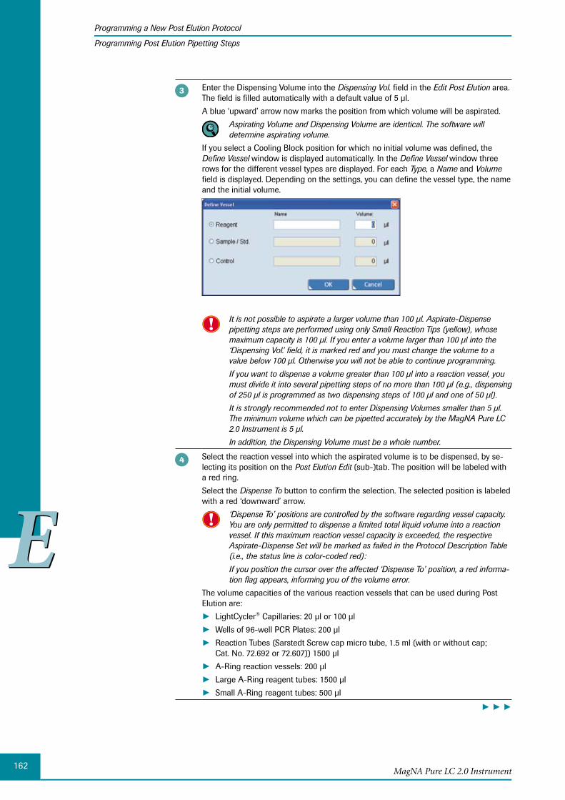
162
EE
MagNA Pure LC 2.0 Instrument
Programming a New Post Elution Protocol
Programming Post Elution Pipetting Steps
Enter the Dispensing Volume into the Dispensing Vol. field in the Edit Post Elution area. The field is filled automatically with a default value of 5 µl.
A blue ‘upward’ arrow now marks the position from which volume will be aspirated.
Aspirating Volume and Dispensing Volume are identical. The software will determine aspirating volume.
If you select a Cooling Block position for which no initial volume was defined, the Define Vessel window is displayed automatically. In the Define Vessel window three rows for the different vessel types are displayed. For each Type, a Name and Volume field is displayed. Depending on the settings, you can define the vessel type, the name and the initial volume.
It is not possible to aspirate a larger volume than 100 µl. Aspirate-Dispense pipetting steps are performed using only Small Reaction Tips (yellow), whose maximum capacity is 100 µl. If you enter a volume larger than 100 µl into the ‘Dispensing Vol.’ field, it is marked red and you must change the volume to a value below 100 µl. Otherwise you will not be able to continue programming.
If you want to dispense a volume greater than 100 µl into a reaction vessel, you must divide it into several pipetting steps of no more than 100 µl (e.g., dispensing of 250 µl is programmed as two dispensing steps of 100 µl and one of 50 µl).
It is strongly recommended not to enter Dispensing Volumes smaller than 5 µl. The minimum volume which can be pipetted accurately by the MagNA Pure LC 2.0 Instrument is 5 µl.
In addition, the Dispensing Volume must be a whole number.
Select the reaction vessel into which the aspirated volume is to be dispensed, by se-lecting its position on the Post Elution Edit (sub-)tab. The position will be labeled with a red ring.
Select the Dispense To button to confirm the selection. The selected position is labeled with a red ‘downward’ arrow.
‘Dispense To’ positions are controlled by the software regarding vessel capacity. You are only permitted to dispense a limited total liquid volume into a reaction vessel. If this maximum reaction vessel capacity is exceeded, the respective Aspirate-Dispense Set will be marked as failed in the Protocol Description Table (i.e., the status line is color-coded red):
If you position the cursor over the affected ‘Dispense To’ position, a red informa-tion flag appears, informing you of the volume error.
The volume capacities of the various reaction vessels that can be used during Post Elution are:
LightCycler ► ® Capillaries: 20 µl or 100 µl
Wells of 96-well PCR Plates: 200 µl ►Reaction Tubes (Sarstedt Screw cap micro tube, 1.5 ml (with or without cap; ►Cat. No. 72.692 or 72.607)) 1500 µl
A-Ring reaction vessels: 200 µl ►Large A-Ring reagent tubes: 1500 µl ►Small A-Ring reagent tubes: 500 µl ►
► ► ►

163
EE
Post Elution
Programming a New Post Elution Protocol
Programming Post Elution Pipetting Steps
Check the Discard Tips option, if you want to discard the Reaction Tips after the pi-petting step was performed.
The ‘Discard Tips’ option is active by default. If you deactivate the function, it will automatically be activated again, when you program the next Aspirate-Dispense Set.
Check the Pause option, if you want to pause the Post Elution run after completion of the current Aspirate-Dispense Set. The status line of the Aspirate-Dispense Set will be color-coded white.
Select Done to confirm programming of the complete Aspirate-Dispense Set. The programmed Aspirate-Dispense Set is displayed in the Protocol Description Table.
■
If you want to verify the Aspirate-Dispense Set, select it in the Protocol Description Table by selecting the appropriate line numbers. The corresponding Aspirate-Dispense Set is highlighted blue and you see the corresponding Aspirate From and Dispense To positions.
Programming an Aspirate-Dispense Set: Aspirate from one vessel – dispense into several vessels (1:n multi-dispensing)
When the same volume of one reagent (e.g., PCR master mix or water for dilution series) is to be pipetted into several different reaction vessels, it is more timesaving to program this as a 1:n multi-dispensing step, than as several individual 1:1 single-dispensing steps. This is done by selecting all reaction vessels into which the liquid volume should be dis-pensed simultaneously.
Although programming of the dispensing steps is done in one step, the actual pipetting steps are performed individually. It is not possible to aspirate the complete volume required for several sequential pipetting steps and to dispense it successively.
Select the Aspirate From position and specify the Dispensing Volume as described in section Programming an Aspirate-Dispense Set: Aspirate from one vessel – dispense into one vessel (1:1 single-dispensing).
To select all reaction vessels into which the aspirated volume is to be dispensed, select the first reaction vessel, then holding the <Shift> key, select the last reaction vessel. All reaction vessels between the first and last one will be selected automatically.
You can select reaction vessels that are not in sequence without holding the <Shift> key.
You can select a reaction vessel, to add or remove individual reaction vessels, to or from the sequence. The positions will be labeled with a red ring.
Select the Dispense To button to confirm your selection.
All Dispense To positions are now labeled with a red ‘downward’ arrow.
► ► ►
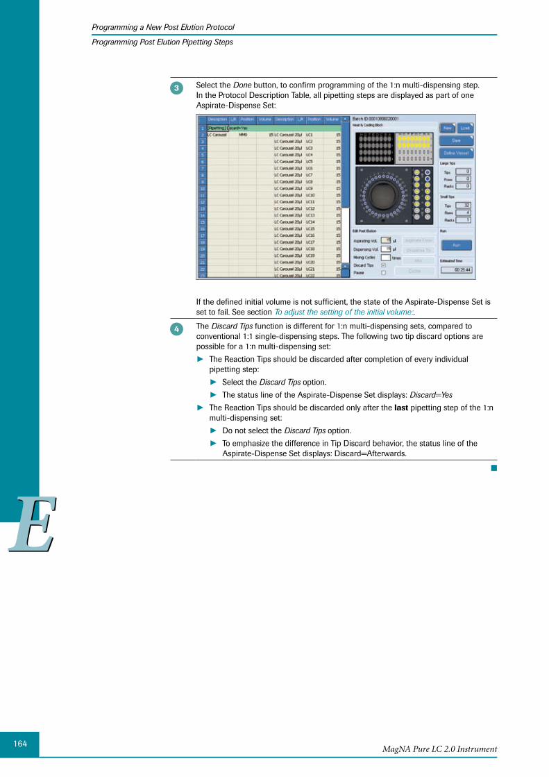
164
EE
MagNA Pure LC 2.0 Instrument
Programming a New Post Elution Protocol
Programming Post Elution Pipetting Steps
Select the Done button, to confirm programming of the 1:n multi-dispensing step. In the Protocol Description Table, all pipetting steps are displayed as part of one Aspirate-Dispense Set:
If the defined initial volume is not sufficient, the state of the Aspirate-Dispense Set is set to fail. See section To adjust the setting of the initial volume:.
The Discard Tips function is different for 1:n multi-dispensing sets, compared to conventional 1:1 single-dispensing steps. The following two tip discard options are possible for a 1:n multi-dispensing set:
The Reaction Tips should be discarded after completion of every individual ► pipetting step:
Select the ► Discard Tips option.
The status line of the Aspirate-Dispense Set displays: ► Discard=Yes
The Reaction Tips should be discarded only after the ► last pipetting step of the 1:n multi-dispensing set:
Do not select the ► Discard Tips option.
To emphasize the difference in Tip Discard behavior, the status line of the ►Aspirate-Dispense Set displays: Discard=Afterwards.
■
165
EE
Post Elution
Programming a New Post Elution Protocol
Programming Post Elution Pipetting Steps
To adjust the setting of the initial volume:
If the initial volume defined in the Post Elution Define Name / Set Volume window is not sufficient to perform all programmed pipetting steps, the respective Aspirate- Dispense Set will be labeled as failed (the status line is displayed in red).
If you select the affected Aspirate From position, an information flag appears displaying volume information:
Needed Vol. ► : The additional volume required to perform all programmed pipetting steps, calculated after the last performable pipetting step.
Needed Initial ► : The initial volume (InitVol) that must be set by the user and pre-pipetted into the reaction vessel to allow performance of all programmed pipetting steps.
Adjust the initial volume of the Aspirate From position to the correct volume and ensure that enough liquid is present in the reaction vessel.
Select the reaction vessel whose initial volume you want to change, by selecting its position on the Post Elution Edit (sub-)tab.
You may select several individual vessels at a time, by selecting their respective positions, or a range of positions, by selecting the first and last position, while holding the <Shift> key. The selected positions are labeled with a red ring.
Select the Define Vessel button to open the Define Vessel window.
You can now define the type of the vessel and enter the name and the new initial volume, see section Defining Type, Name and Initial Volume of Cooling Block Positions.
If several vessels are selected at the same time, all will be assigned with the same type and the same ‘InitVol.’. The ‘Name’ field is not accessible in this case.
■
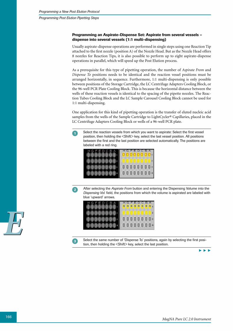
166
EE
MagNA Pure LC 2.0 Instrument
Programming a New Post Elution Protocol
Programming Post Elution Pipetting Steps
Programming an Aspirate-Dispense Set: Aspirate from several vessels – dispense into several vessels (1:1 multi-dispensing)
Usually aspirate-dispense operations are performed in single steps using one Reaction Tip attached to the first nozzle (position A) of the Nozzle Head. But as the Nozzle Head offers 8 nozzles for Reaction Tips, it is also possible to perform up to eight aspirate-dispense operations in parallel, which will speed up the Post Elution process.
As a prerequisite for this type of pipetting operation, the number of Aspirate From and Dispense To positions needs to be identical and the reaction vessel positions must be arranged horizontally, in sequence. Furthermore, 1:1 multi-dispensing is only possible between positions of the Storage Cartridge, the LC Centrifuge Adapters Cooling Block, or the 96-well PCR Plate Cooling Block. This is because the horizontal distance between the wells of these reaction vessels is identical to the spacing of the pipette nozzles. The Reac-tion Tubes Cooling Block and the LC Sample Carousel Cooling Block cannot be used for 1:1 multi-dispensing.
One application for this kind of pipetting operation is the transfer of eluted nucleic acid samples from the wells of the Sample Cartridge to LightCycler® Capillaries, placed in the LC Centrifuge Adapters Cooling Block or wells of a 96-well PCR plate.
Select the reaction vessels from which you want to aspirate: Select the first vessel position, then holding the <Shift> key, select the last vessel position. All positions between the first and the last position are selected automatically. The positions are labeled with a red ring.
After selecting the Aspirate From button and entering the Dispensing Volume into the Dispensing Vol. field, the positions from which the volume is aspirated are labeled with blue ‘upward’ arrows.
Select the same number of ‘Dispense To’ positions, again by selecting the first posi-tion, then holding the <Shift> key, select the last position.
► ► ►
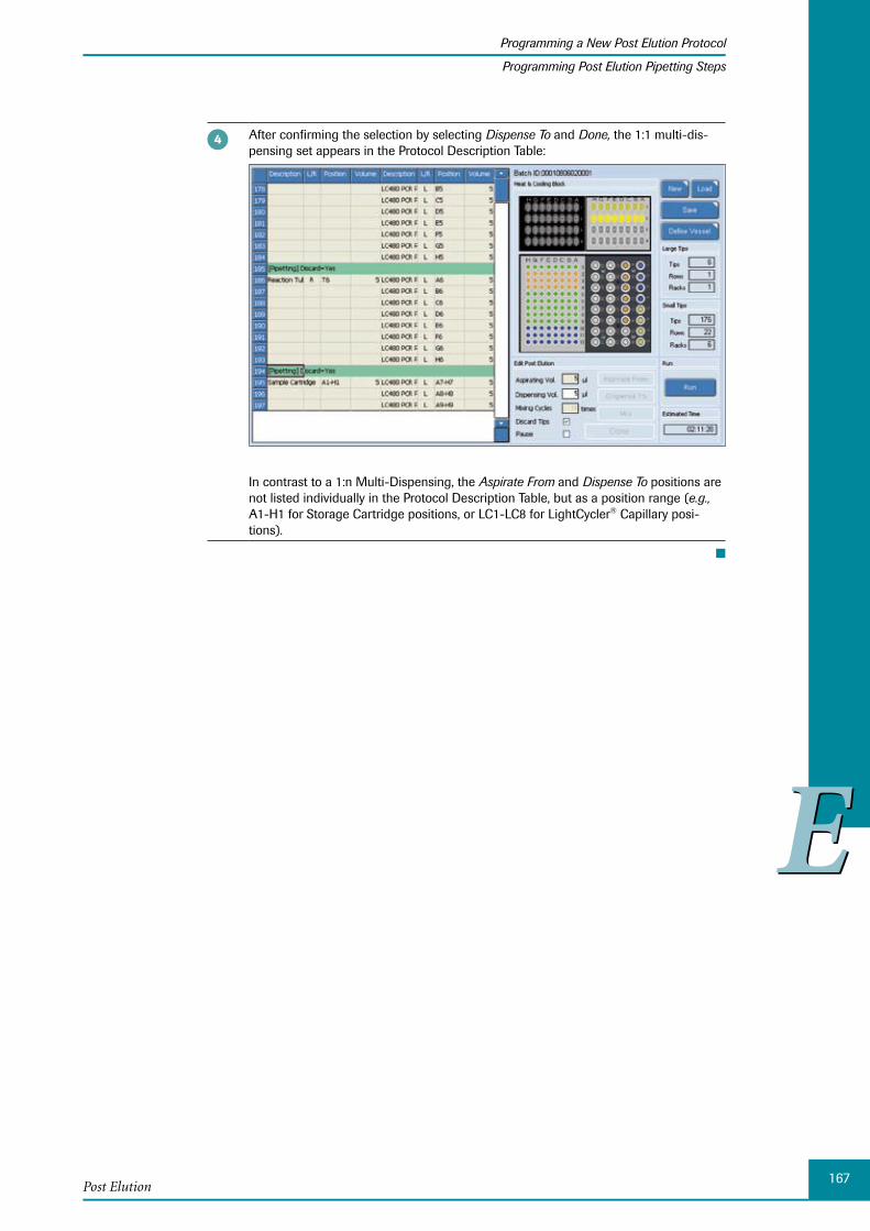
167
EE
Post Elution
Programming a New Post Elution Protocol
Programming Post Elution Pipetting Steps
After confirming the selection by selecting Dispense To and Done, the 1:1 multi-dis-pensing set appears in the Protocol Description Table:
In contrast to a 1:n Multi-Dispensing, the Aspirate From and Dispense To positions are not listed individually in the Protocol Description Table, but as a position range (e.g., A1-H1 for Storage Cartridge positions, or LC1-LC8 for LightCycler® Capillary posi-tions).
■
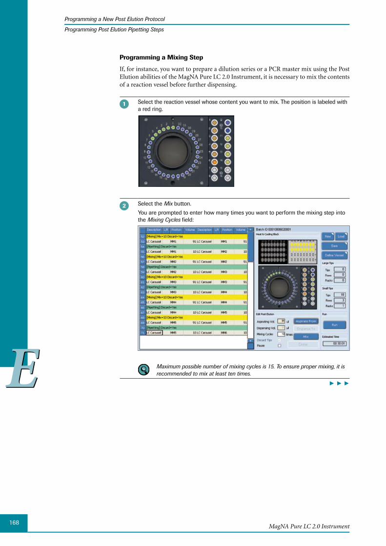
168
EE
MagNA Pure LC 2.0 Instrument
Programming a New Post Elution Protocol
Programming Post Elution Pipetting Steps
Programming a Mixing Step
If, for instance, you want to prepare a dilution series or a PCR master mix using the Post Elution abilities of the MagNA Pure LC 2.0 Instrument, it is necessary to mix the contents of a reaction vessel before further dispensing.
Select the reaction vessel whose content you want to mix. The position is labeled with a red ring.
Select the Mix button.
You are prompted to enter how many times you want to perform the mixing step into the Mixing Cycles field:
Maximum possible number of mixing cycles is 15. To ensure proper mixing, it is recommended to mix at least ten times.
► ► ►
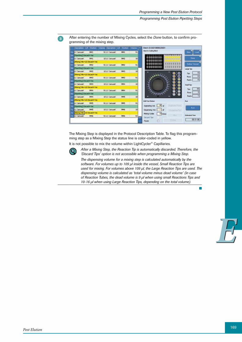
169
EE
Post Elution
Programming a New Post Elution Protocol
Programming Post Elution Pipetting Steps
After entering the number of Mixing Cycles, select the Done button, to confirm pro-gramming of the mixing step.
The Mixing Step is displayed in the Protocol Description Table. To flag this program-ming step as a Mixing Step the status line is color-coded in yellow.
It is not possible to mix the volume within LightCycler® Capillaries.
After a Mixing Step, the Reaction Tip is automatically discarded. Therefore, the ‘Discard Tips’ option is not accessible when programming a Mixing Step.
The dispensing volume for a mixing step is calculated automatically by the software. For volumes up to 109 µl inside the vessel, Small Reaction Tips are used for mixing. For volumes above 109 µl, the Large Reaction Tips are used. The dispensing volume is calculated as ‘total volume minus dead volume’ (in case of Reaction Tubes, the dead volume is 9 µl when using small Reactions Tips and 10-16 µl when using Large Reaction Tips, depending on the total volume).
■
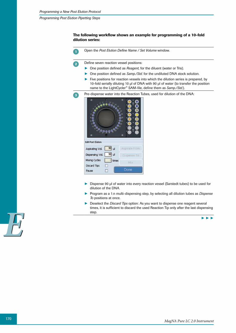
170
EE
MagNA Pure LC 2.0 Instrument
Programming a New Post Elution Protocol
Programming Post Elution Pipetting Steps
The following workflow shows an example for programming of a 10-fold dilution series:
Open the Post Elution Define Name / Set Volume window.
Define seven reaction vessel positions:
One position defined as ► Reagent, for the diluent (water or Tris).
One position defined as ► Samp./Std. for the undiluted DNA stock solution.
Five positions for reaction vessels into which the dilution series is prepared, by ►10-fold serially diluting 10 µl of DNA with 90 µl of water (to transfer the position name to the LightCycler® SAM-file, define them as Samp./Std.).
Pre-dispense water into the Reaction Tubes, used for dilution of the DNA:
Dispense 90 µl of water into every reaction vessel (Sarstedt tubes) to be used for ►dilution of the DNA.
Program as a 1:n multi-dispensing step, by selecting all dilution tubes as ► Dispense To positions at once.
Deselect the ► Discard Tips option: As you want to dispense one reagent several times, it is sufficient to discard the used Reaction Tip only after the last dispensing step.
► ► ►
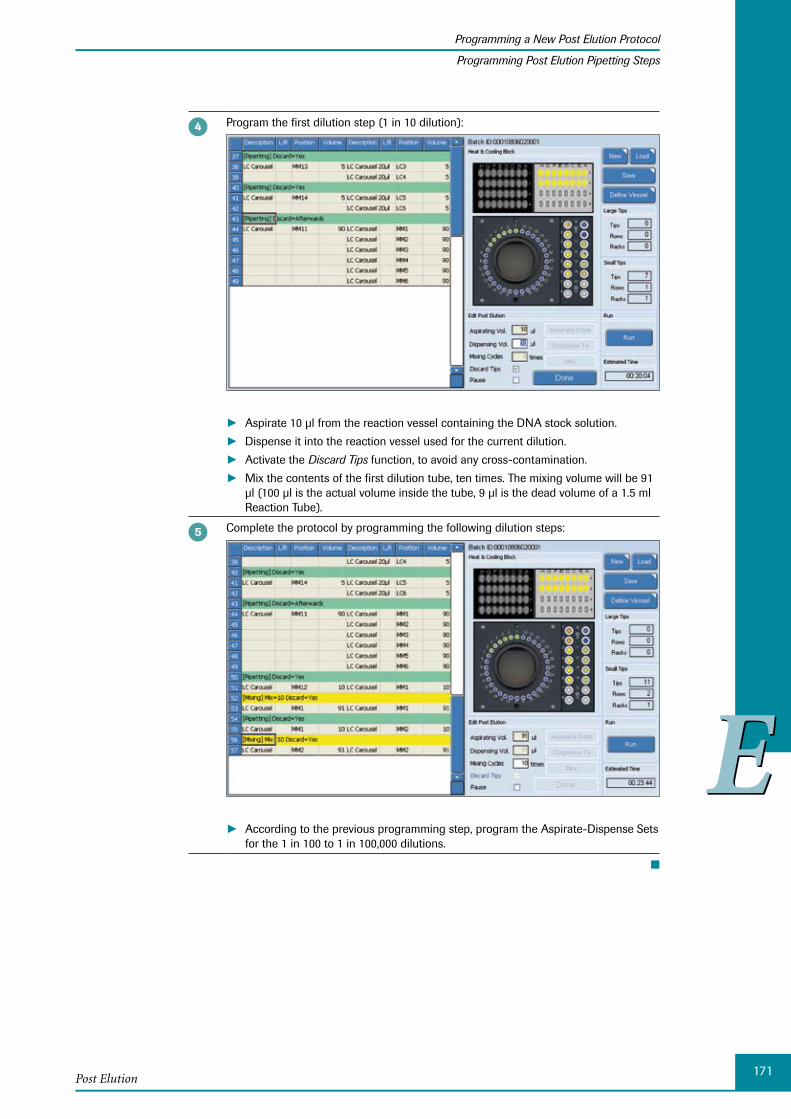
171
EE
Post Elution
Programming a New Post Elution Protocol
Programming Post Elution Pipetting Steps
Program the first dilution step (1 in 10 dilution):
Aspirate 10 µl from the reaction vessel containing the DNA stock solution. ►Dispense it into the reaction vessel used for the current dilution. ►Activate the ► Discard Tips function, to avoid any cross-contamination.
Mix the contents of the first dilution tube, ten times. The mixing volume will be 91 ►µl (100 µl is the actual volume inside the tube, 9 µl is the dead volume of a 1.5 ml Reaction Tube).
Complete the protocol by programming the following dilution steps:
According to the previous programming step, program the Aspirate-Dispense Sets ►for the 1 in 100 to 1 in 100,000 dilutions.
■

172
EE
MagNA Pure LC 2.0 Instrument
Saving and Loading a Post Elution Protocol
4 Saving and Loading a Post Elution Protocol
You can save programmed Post Elution protocols, then load and edit the data later.
To save a Post Elution protocol:
After you have programmed a new Post Elution protocol or modified an existing one, you can save the Post Elution protocol file (*.pep) for further use.
On the Post Elution Edit (sub-)tab, select the Save button.
The Save as window is displayed. The PostElution directory within the MagNA Pure directory is opened automatically.
Define a name and select Save, to confirm saving of the Post Elution protocol (*.pep) file.
■
It is possible to load a Post Elution protocol which was created by another user. To prevent changes to another user’s protocol, changes made by the second user can only be saved under a different file name.
In the Post Elution protocol, all parameters and settings of the reaction vessel positions and Aspirate-Dispense Sets are saved. Also information on the samples, which are present within the Sample Cartridge during programming of the protocol are saved. Therefore, when loading the Post Elution protocol the next time, ensure that actual and saved sample data match, to enable correct processing of the Post Elution proto-col.
To load a Post Elution protocol:
You can load a previously saved Post Elution protocol file and modify it.
Select Load on the Post Elution Edit (sub-)tab.
If a newly created or modified Post Elution protocol, not saved already, is still displayed in the Protocol Description Table, a warning message is displayed.
Select ► Yes, if you want to save the changed Post Elution protocol.
Select ► No, if you directly want to load a new Post Elution protocol file. Any unsaved protocol data will be lost.
The Open window is displayed. The Post Elution protocol directory within the MagNA Pure directory is opened automatically.
Select the Post Elution protocol (*.pep) file you want to load and select Open to con-firm.
■
If you load a Post Elution protocol which includes the MagNA Pure LC Cooling Block, A-Ring, you are prompted to enter the bar code(s) of the COBAS® AmpliCor® A-Ring(s).
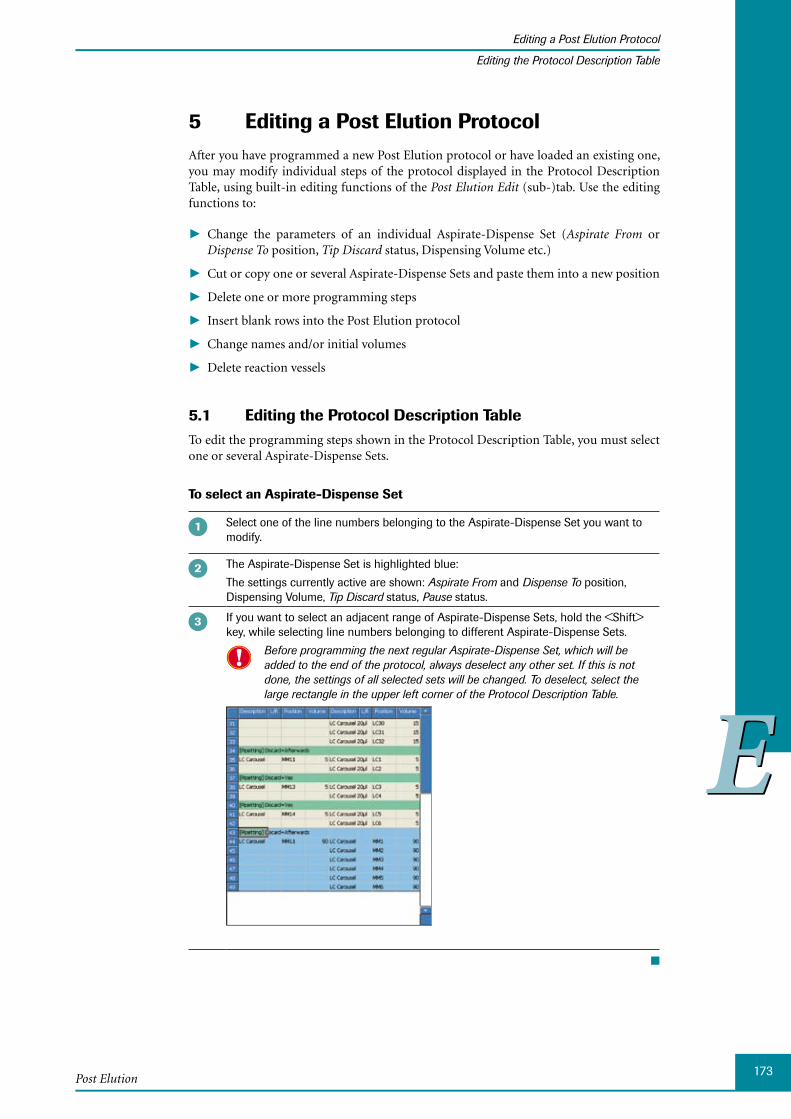
173
EE
Post Elution
Editing a Post Elution Protocol
Editing the Protocol Description Table
Editing a 5 Post Elution ProtocolAfter you have programmed a new Post Elution protocol or have loaded an existing one, you may modify individual steps of the protocol displayed in the Protocol Description Table, using built-in editing functions of the Post Elution Edit (sub-)tab. Use the editing functions to:
Change the parameters of an individual Aspirate-Dispense Set ( ► Aspirate From or Dispense To position, Tip Discard status, Dispensing Volume etc.)
Cut or copy one or several Aspirate-Dispense Sets and paste them into a new position ►
Delete one or more programming steps ►
Insert blank rows into the Post Elution protocol ►
Change names and/or initial volumes ►
Delete reaction vessels ►
Editing the 5.1 Protocol Description TableTo edit the programming steps shown in the Protocol Description Table, you must select one or several Aspirate-Dispense Sets.
To select an Aspirate-Dispense Set
Select one of the line numbers belonging to the Aspirate-Dispense Set you want to modify.
The Aspirate-Dispense Set is highlighted blue:
The settings currently active are shown: Aspirate From and Dispense To position, Dispensing Volume, Tip Discard status, Pause status.
If you want to select an adjacent range of Aspirate-Dispense Sets, hold the <Shift> key, while selecting line numbers belonging to different Aspirate-Dispense Sets.
Before programming the next regular Aspirate-Dispense Set, which will be added to the end of the protocol, always deselect any other set. If this is not done, the settings of all selected sets will be changed. To deselect, select the large rectangle in the upper left corner of the Protocol Description Table.
■
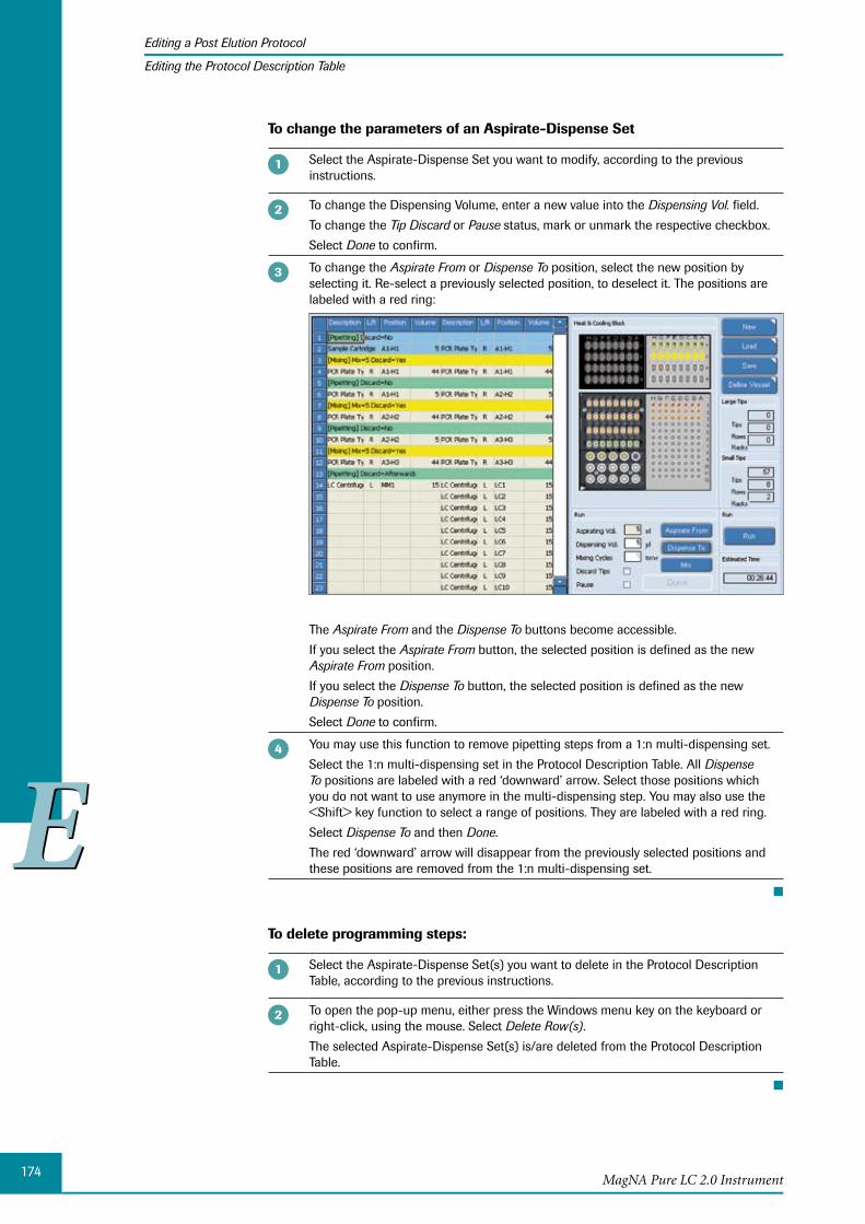
174
EE
MagNA Pure LC 2.0 Instrument
Editing a Post Elution Protocol
Editing the Protocol Description Table
To change the parameters of an Aspirate-Dispense Set
Select the Aspirate-Dispense Set you want to modify, according to the previous instructions.
To change the Dispensing Volume, enter a new value into the Dispensing Vol. field.
To change the Tip Discard or Pause status, mark or unmark the respective checkbox.
Select Done to confirm.
To change the Aspirate From or Dispense To position, select the new position by selecting it. Re-select a previously selected position, to deselect it. The positions are labeled with a red ring:
The Aspirate From and the Dispense To buttons become accessible.
If you select the Aspirate From button, the selected position is defined as the new Aspirate From position.
If you select the Dispense To button, the selected position is defined as the new Dispense To position.
Select Done to confirm.
You may use this function to remove pipetting steps from a 1:n multi-dispensing set.
Select the 1:n multi-dispensing set in the Protocol Description Table. All Dispense To positions are labeled with a red ‘downward’ arrow. Select those positions which you do not want to use anymore in the multi-dispensing step. You may also use the <Shift> key function to select a range of positions. They are labeled with a red ring.
Select Dispense To and then Done.
The red ‘downward’ arrow will disappear from the previously selected positions and these positions are removed from the 1:n multi-dispensing set.
■
To delete programming steps:
Select the Aspirate-Dispense Set(s) you want to delete in the Protocol Description Table, according to the previous instructions.
To open the pop-up menu, either press the Windows menu key on the keyboard or right-click, using the mouse. Select Delete Row(s).
The selected Aspirate-Dispense Set(s) is/are deleted from the Protocol Description Table.
■
175
EE
Post Elution
Editing a Post Elution Protocol
Editing the Protocol Description Table
To use the Copy-Paste function:
Select the Aspirate-Dispense Set you want to copy in the Protocol Description Table, according to the previous instructions.
To open the pop-up menu, either press the Windows menu key on the keyboard or right-click, using the mouse. Select Copy.
To open the pop-up menu again, either press the Windows menu key on the keyboard or right-click, using the mouse.
If you select ► Paste from the pop-up menu, the copied Aspirate-Dispense Set will be pasted at the end of the Protocol Description Table.
If you want to paste the copied set within the Protocol Description Table, select the ►Aspirate-Dispense Set prior to where you want to paste the copied set. Open the pop-up menu and select Paste After. The previously copied Aspirate-Dispense Set is inserted after the selected set.
■
You may use this function if you want to program a set of identical Aspirate-Dispense Sets which are to be performed sequentially. For e.g., if you want to dispense a volume larger than 100 µl, you must program this in several steps with a maximal size of 100 µl each. If, for instance, you want to dispense 400 µl, program the step for dispensing 100 µl just once. Copy this Aspirate-Dispense Set and paste it three times after the initial 100 µl Aspirate-Dispense Set.
If you select ‘Cut’ instead of ‘Copy’, the selected Aspirate-Dispense Set is copied to the clipboard memory and deleted from the original position at the same time.
To insert blank rows into a Post Elution protocol:
If you want to insert a new Aspirate-Dispense Set within an existing Post Elution protocol, you must create a new empty row first.
Select the Aspirate-Dispense Set from the Protocol Description Table before or after where you want to insert a blank row.
To open the pop-up menu, either press the Windows menu key on the keyboard or right-click, using the mouse. Select Insert a Blank Row or Insert a Blank Row After.
According to the selected function, a blank row is added before or after the selected Aspirate-Dispense Set.
To insert a new Aspirate-Dispense Set at the position of the blank row, select the row and program an Aspirate-Dispense Set or Mixing Cycle, as outlined in detail in Programming Post Elution Pipetting Steps.
Select Done to confirm the Aspirate-Dispense Set. The new Aspirate-Dispense Set replaces the previously inserted blank row.
■

176
EE
MagNA Pure LC 2.0 Instrument
Editing a Post Elution Protocol
Editing Reaction Vessel Parameters
5.2 Editing Reaction Vessel ParametersYou can modify specific parameters, e.g., name, type, or initial volume, for every reaction vessel.
To change parameters of a reaction vessel position:
Select the vessel you want to modify.
You may select several individual vessels at a time, by selecting their respective positions, or a range of positions by selecting the first and last position, while holding the <Shift> key. The selected positions are labeled with a red ring.
Select the Define Vessel button. The Define Vessel window is displayed. For a detailed description, see section The Post Elution Define Name / Set Volume Window.
You can now define the type of the vessel, its name and its initial volume (if neces-sary).
Define the Type of the reaction vessel by checking Reagent, Samp./Std., or Control.
Defining a reaction vessel as ‘Control’ is especially useful when setting up reactions for COBAS® AmpliCor® Instrument tests in the A-Ring Cooling Block.
Enter the name into the Name field.
If several vessels are selected at the same time, all will be assigned to the same ‘Type’ and the same ‘InitVol.’ The ‘Name’ field is not accessible in this case.
Enter the new initial volume into the ‘Volume’ field. If an InitVol. was already specified, the current value is displayed.
Select OK, to confirm your entry.
■
To remove a reaction vessel:
Select the vessel you want to remove.
You may select several individual vessels at a time, by selecting their respective positions, or a range of positions by selecting the first and last position, while holding the <Shift> key. The selected positions are labeled with a red ring.
Select the Define Vessel button. The Define Vessel window is displayed.
Select the Remove button. A warning is displayed.
Select OK, to confirm and delete the vessel.
■
It is only possible to remove master mix positions from a Cooling Block, but not Light-Cycler® Capillary positions or positions from a 96-well plate.
Only the reaction vessel will be removed from the Cooling Block. All Aspirate-Dispense Sets from the active Post Elution protocol connected to this reaction vessel, will remain and are displayed as failed, after removing the vessel.
177
EE
Post Elution
Starting and Stopping a Post Elution Run or a Post Elution Simulation
Starting and Stopping a Post Elution Run 6 or a Post Elution Simulation
MagNA Pure LC 2.0 System only:
Before you start a Post Elution run:
Ensure that no obstacles are present on the Reagent/Sample Stage.
To ensure pipetting of correct volumes, it is important that all reagents pipetted manu-ally into reaction tubes are centrifuged to remove air bubbles and to ensure that the reagents have reached Cooling Block temperature (temperature equilibration requires approx. 10 min, when using reagents from room temperature, or 20 min, when using reagents previously stored on ice, respectively).
To ensure correct pipetting, it is also necessary to use only 1.5ml Sarstedt Reaction Tubes with screw caps (Cat. No. 72.692 or 72.607).
Sometimes air bubbles might become trapped at the bottom of a Storage Cartridge well. To ensure that the complete defined sample volume is aspirated, always check the Storage Cartridge for air bubbles. If necessary remove air bubbles manually.
Ensure that enough Reaction Tips are present on the Reagent/Sample Stage.
To start a Post Elution run, it is necessary that Cooling Unit 1 (Storage Cartridge) and Cooling Unit 2 (MagNA Pure LC Cooling Block) have reached their working temperature of 7.5°C. You can check the temperature status of both Cooling Units using the buttons named ‘Storage’ and ‘Cooling Unit’ in the ‘Elution/Post Elution’ area of the ‘Overview’ tab. For a detailed description, see section Instrument Area. The Post Elution run can be started prior to the Heating and Cooling Units reaching their final temperatures, but the actual pipetting process will not start before the temperature is reached.
To start a Post Elution run or a Post Elution simulation:
MagNA Pure LC 2.0 System only: Check that all reagents and Reaction Tips are loaded on to the Reagent/Sample Stage and that the Disposable Lock Bar is locked and the Instrument Door is closed.
Select Run on the Post Elution Edit (sub-)tab. A pop-up window is displayed, asking to start the Post Elution run.
Select OK, to confirm the pop-up window and start the Post Elution run or the Post Elution simulation.
■
If the current Post Elution protocol was not yet saved, a message window opens, prompting you to save the Post Elution file: Select ‘Yes’, if you want to save the changed Post Elution protocol. Select ‘No’, if you do not want to save the Post Elution protocol file. Any unsaved protocol data will be lost.
During the Post Elution run currently processed Aspirate-Dispense Sets are highlight-ed in the Protocol Description Table.
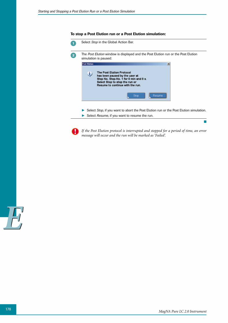
178
EE
MagNA Pure LC 2.0 Instrument
Starting and Stopping a Post Elution Run or a Post Elution Simulation
To stop a Post Elution run or a Post Elution simulation:
Select Stop in the Global Action Bar.
The Post Elution window is displayed and the Post Elution run or the Post Elution simulation is paused:
Select ► Stop, if you want to abort the Post Elution run or the Post Elution simulation.
Select ► Resume, if you want to resume the run.
■
If the Post Elution protocol is interrupted and stopped for a period of time, an error message will occur and the run will be marked as ‘Failed’.

179
EE
Post Elution
Post Elution Results
Post 7 Elution Results The results of the Post Elution run are displayed on the ‘Post Elution Results’ sub-tab
of the MagNA Pure LC 2.0 System or the ‘Simulation Result’ tab of the Post Elution Protocol Editor on an external PC.
To open the Simulation Result tab in the Post Elution Protocol Editor:
On the Post Elution Protocol Editor window, open the Simulation Result tab.
■
To open the Post Elution Results sub-tab in the MagNA Pure LC 2.0 System:
Depending on your settings, the results are sent automatically or you can upload the data manually, see section Setting up Parameters.
Open the Workplace tab in the MagNA Pure LC 2.0 Software.
On the Workplace tab, select Post Elution Results.
The Post Elution Results sub-tab is displayed.
■
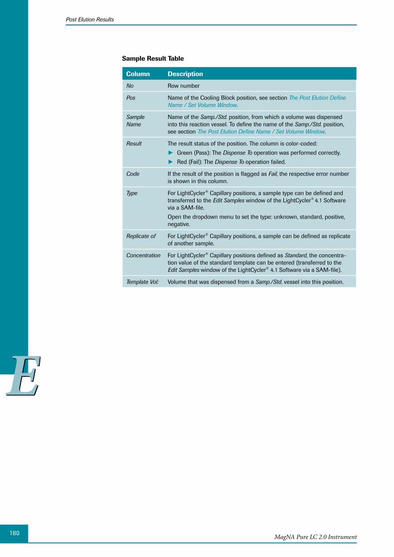
180
EE
MagNA Pure LC 2.0 Instrument
Post Elution Results
Sample Result Table
Column Description
No Row number
Pos Name of the Cooling Block position, see section The Post Elution Define Name / Set Volume Window.
Sample Name
Name of the Samp./Std. position, from which a volume was dispensed into this reaction vessel. To define the name of the Samp./Std. position, see section The Post Elution Define Name / Set Volume Window.
Result The result status of the position. The column is color-coded:
Green (Pass): The ► Dispense To operation was performed correctly.
Red (Fail): The ► Dispense To operation failed.
Code If the result of the position is flagged as Fail, the respective error number is shown in this column.
Type For LightCycler® Capillary positions, a sample type can be defined and transferred to the Edit Samples window of the LightCycler® 4.1 Software
via a SAM-file.
Open the dropdown menu to set the type: unknown, standard, positive, negative.
Replicate of For LightCycler® Capillary positions, a sample can be defined as replicate of another sample.
Concentration For LightCycler® Capillary positions defined as Standard, the concentra-tion value of the standard template can be entered (transferred to the Edit Samples window of the LightCycler® 4.1 Software via a SAM-file).
Template Vol: Volume that was dispensed from a Samp./Std. vessel into this position.
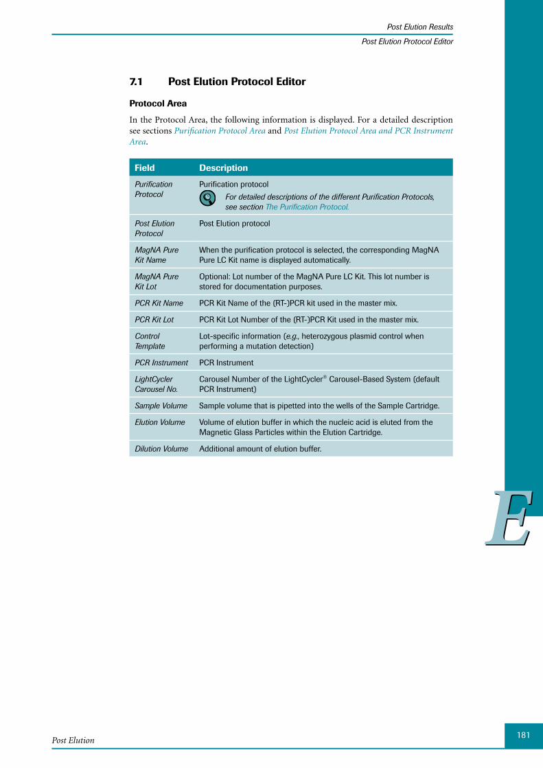
181
EE
Post Elution
Post Elution Results
Post Elution Protocol Editor
Post Elution Protocol Editor7.1
Protocol Area
In the Protocol Area, the following information is displayed. For a detailed description see sections Purification Protocol Area and Post Elution Protocol Area and PCR Instrument Area.
Field Description
Purification Protocol
Purification protocol
For detailed descriptions of the different Purification Protocols, see section The Purification Protocol.
Post Elution Protocol
Post Elution protocol
MagNA Pure Kit Name
When the purification protocol is selected, the corresponding MagNA Pure LC Kit name is displayed automatically.
MagNA Pure Kit Lot
Optional: Lot number of the MagNA Pure LC Kit. This lot number is stored for documentation purposes.
PCR Kit Name PCR Kit Name of the (RT-)PCR kit used in the master mix.
PCR Kit Lot PCR Kit Lot Number of the (RT-)PCR Kit used in the master mix.
Control Template
Lot-specific information (e.g., heterozygous plasmid control when performing a mutation detection)
PCR Instrument PCR Instrument
LightCycler Carousel No.
Carousel Number of the LightCycler® Carousel-Based System (default PCR Instrument)
Sample Volume Sample volume that is pipetted into the wells of the Sample Cartridge.
Elution Volume Volume of elution buffer in which the nucleic acid is eluted from the Magnetic Glass Particles within the Elution Cartridge.
Dilution Volume Additional amount of elution buffer.
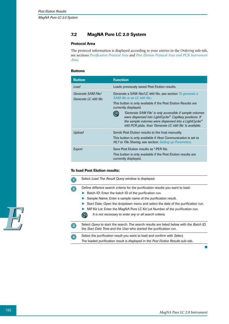
182
EE
MagNA Pure LC 2.0 Instrument
Post Elution Results
MagNA Pure LC 2.0 System
MagNA Pure LC 2.0 System7.2
Protocol Area
The protocol information is displayed according to your entries in the Ordering sub-tab, see sections Purification Protocol Area and Post Elution Protocol Area and PCR Instrument Area.
Buttons
Button Function
Load Loads previously saved Post Elution results.
Generate SAM File/
Generate LC 480 file
Generate a SAM-file/LC 480 file, see section To generate a SAM-file or an LC 480 file:.
This button is only available if the Post Elution Results are currently displayed.
‘Generate SAM File’ is only accessible if sample volumes were dispensed into LightCycler® Capillary positions. If the sample volumes were dispensed into a LightCycler® 480 PCR plate, than ‘Generate LC 480 file’ is available.
Upload Sends Post Elution results to the host manually.
This button is only available if Host Communication is set to HL7 or File Sharing, see section Setting up Parameters.
Export Save Post Elution results as *.PER file.
This button is only available if the Post Elution results are currently displayed.
To load Post Elution results:
Select Load. The Result Query window is displayed.
Define different search criteria for the purification results you want to load:
Batch ID: Enter the batch ID of the purification run. ►Sample Name: Enter a sample name of the purification result. ►Start Date: Open the dropdown menu and select the date of the purification run. ►MP Kit Lot: Enter the MagNA Pure LC Kit Lot Number of the purification run. ► It is not necessary to enter any or all search criteria.
Select Query to start the search. The search results are listed below with the Batch ID, the Start Date Time and the User who started the purification run.
Select the purification result you want to load and confirm with Select.
The loaded purification result is displayed in the Post Elution Results sub-tab.
■
183
EE
Post Elution
Post Elution Results
MagNA Pure LC 2.0 System
To generate a SAM-file or an LC 480 file:
If during Post Elution pipetting, sample volumes were dispensed into LightCycler® Capillaries, capillary specific sample data of the Post Elution Results sub-tab can be saved into a LightCycler® sample file (*.sam) and reloaded into the Edit Samples window of the LightCycler® 4.1 software.
If during Post Elution pipetting, sample volumes were dispensed into a LightCycler® 480 PCR plate, sample data of the Post Elution Results sub-tab can be saved into a text file (*.txt) and reloaded into the LightCycler® 4.1 software.
If you perform two Post Elution runs from the same Batch Results, please be aware that the Post Elution Results will contain the same Batch ID. Thus, the name of the SAM-file or LC 480 text file will also be the same.
You can edit LightCycler® specific sample parameters like type, replicate of and concen-tration.
Select Generate SAM file / Generate LC 480 file. The Save window is displayed. The PostElutionResult directory within the MagNA Pure directory is opened automatically.
Choose an appropriate drive and folder and select Save.
The name of the file is generated automatically by the software, plus the letter ‘L’ or ‘R’, for the left and right Cooling Blocks, respectively.
■
To upload Post Elution results:
Select Upload.
The Post Elution results are uploaded to the set host.
■
To export Post Elution results:
Select Export. The Save as window is displayed.
Select the device to where the file should be saved.
Enter the name of the file and select Save.
■
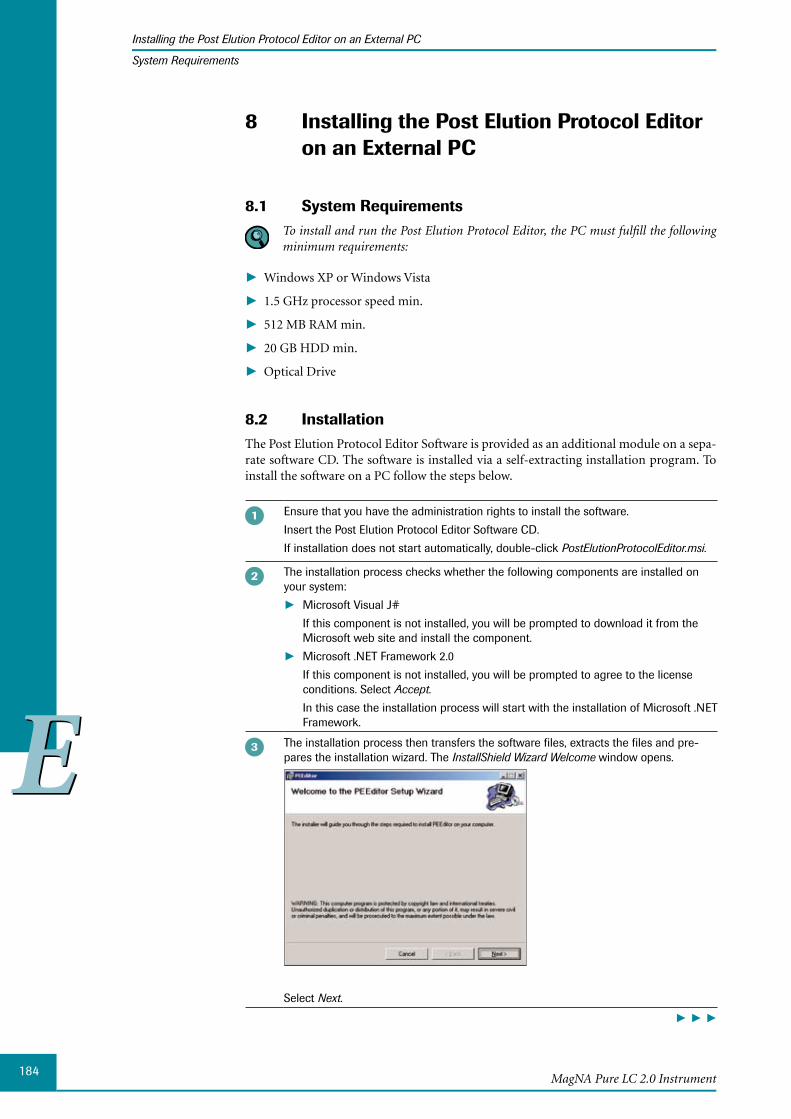
184
EE
MagNA Pure LC 2.0 Instrument
Installing the Post Elution Protocol Editor on an External PC
System Requirements
8 Installing the Post Elution Protocol Editor on an External PC
System Requirements8.1 To install and run the Post Elution Protocol Editor, the PC must fulfill the following
minimum requirements:
Windows XP or Windows Vista ►
1.5 GHz processor speed min. ►
512 MB RAM min. ►
20 GB HDD min. ►
Optical Drive ►
Installation8.2 The Post Elution Protocol Editor Software is provided as an additional module on a sepa-rate software CD. The software is installed via a self-extracting installation program. To install the software on a PC follow the steps below.
Ensure that you have the administration rights to install the software.
Insert the Post Elution Protocol Editor Software CD.
If installation does not start automatically, double-click PostElutionProtocolEditor.msi.
The installation process checks whether the following components are installed on your system:
Microsoft Visual J# ►If this component is not installed, you will be prompted to download it from the Microsoft web site and install the component.
Microsoft .NET Framework 2.0 ►If this component is not installed, you will be prompted to agree to the license conditions. Select Accept.
In this case the installation process will start with the installation of Microsoft .NET Framework.
The installation process then transfers the software files, extracts the files and pre-pares the installation wizard. The InstallShield Wizard Welcome window opens.
Select Next.
► ► ►
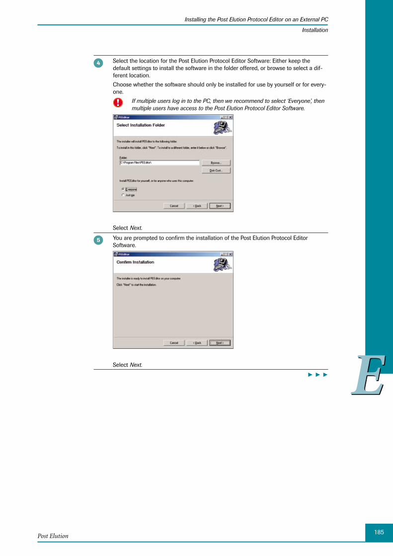
185
EE
Post Elution
Installing the Post Elution Protocol Editor on an External PC
Installation
Select the location for the Post Elution Protocol Editor Software: Either keep the default settings to install the software in the folder offered, or browse to select a dif-ferent location.
Choose whether the software should only be installed for use by yourself or for every-one.
If multiple users log in to the PC, then we recommend to select ‘Everyone’, then multiple users have access to the Post Elution Protocol Editor Software.
Select Next.
You are prompted to confirm the installation of the Post Elution Protocol Editor Software.
Select Next.
► ► ►
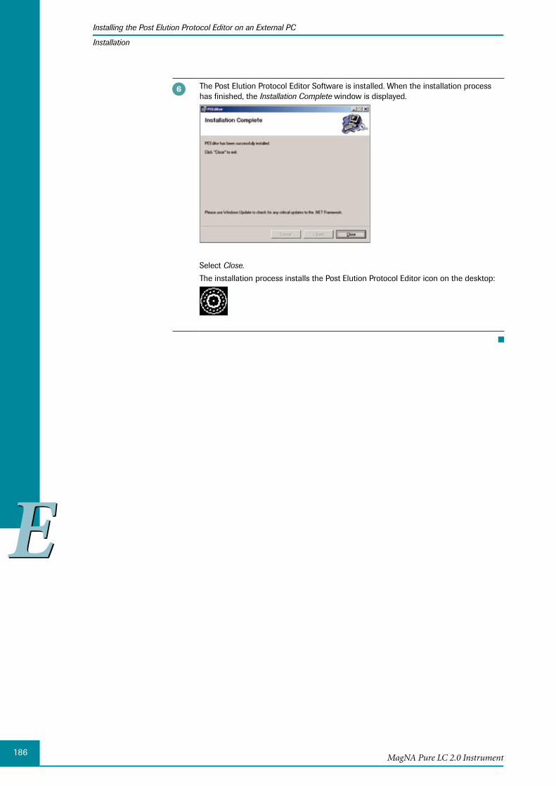
186
EE
MagNA Pure LC 2.0 Instrument
Installing the Post Elution Protocol Editor on an External PC
Installation
The Post Elution Protocol Editor Software is installed. When the installation process has finished, the Installation Complete window is displayed.
Select Close.
The installation process installs the Post Elution Protocol Editor icon on the desktop:
■

Chapter F • Maintenance
188MagNA Pure LC 2.0 Instrument
Table of Contents
FF
F Maintenance
1 User Maintenance .......................................................................................................................................189
1.1 Automated and Manual Greasing of the O-Rings ..............................................................................1901.1.1 Automated Greasing.......................................................................................................................................1901.1.2 Manual Greasing .............................................................................................................................................193
1.2 Changing the O-Rings ...................................................................................................................................1941.3 Leakage Test ......................................................................................................................................................2001.4 Decontamination..............................................................................................................................................202
1.4.1 General Workflow for Decontaminating the MagNA Pure LC 2.0 Instrument .........................2021.4.2 Decontaminating the Instrument ...............................................................................................................2031.4.3 Decontaminating the Nozzle Head ...........................................................................................................2041.4.4 D econtaminating the Inner Parts of the MagNA Pure LC 2.0 Instrument .................................204
1.5 Tip Discard .........................................................................................................................................................2061.6 Changing the Liquid Drop Catcher ...........................................................................................................2061.7 Liquid Waste Discard .....................................................................................................................................2091.8 Home ....................................................................................................................................................................2101.9 Lock Door / Unlock Door ..............................................................................................................................2111.10 Maintenance Reminder .................................................................................................................................2111.11 Create Problem Report ..................................................................................................................................212
2 Service Maintenance .................................................................................................................................213

189
FFMaintenance
User Maintenance
Maintenance
1 User MaintenanceThe MagNA Pure LC 2.0 Instrument was designed to ensure safe operation. However, since biological research sample material may be processed in the Instrument, a possible risk of infection exists. Therefore, when handling potentially infectious material, always follow standard safety procedures and take the following steps, to minimize the chance of contamination or infection:
Always wear a laboratory coat, gloves and a mask, when handling specimens and ► isolation reagents.
Discard unused reagents and waste (solid and liquid), in accordance with country, ►federal, state and local regulations. Material Safety Data Sheets (MSDS) are available upon request from your local Roche office.
Keep the Tip Waste Slide clean. ►
Never operate the Instrument without a Waste Bag inserted into the Waste Box. ►
Discard the Waste Bottle after preparing each full set of samples (32 samples). Discard ►the Waste Bag after 5-7 runs.
After sample preparation is complete: ►
Remove and autoclave all plastic disposables and other waste, then discard. ►
Wipe the Reagent/Sample Stage with bleach (0.5% solution of sodium hypochlo- ►rite), then with 70% ethanol and water.
After using bleach, ventilate the Instrument for at least 1 hour.
After cleaning the Reagent/Sample Stage with bleach and water/ethanol, sterilize the Instrument with UV light (see section Decontaminating the Instrument).
Close the door and select ► Decontamination on the Maintenance sub-tab. For details, see section Decontaminating the Instrument.
Set the decontamination time (recommended setting: at least 8 hours). ►
Select ► Start.
To avoid collisions between the Robotic Arm and the Cooling Blocks, ensure the blocks are seated correctly on the Reagent/Sample Stage. Press the Cooling Blocks firmly, to seat the pins of the blocks in the holes of the Cooling Block 2 Area. After each run, en-sure that the holes in the Cooling Block 2 Area (to fit the pins) are clean. If necessary, clean the holes with a cotton swab to ensure that the Cooling Blocks sit correctly!
If you are handling infectious, potentially infectious or any other dangerous material on the MagNA Pure LC 2.0 Instrument, you must follow your country-specific guide-lines and regulations.
If this Operator’s Manual deviates from your national guidelines in any way, always follow your national guidelines. This may mean, for example, that you must use additional or alternative disinfectants or cleaning methods.
Always discard all liquid or solid waste according to your national regulations.

190
FFMagNA Pure LC 2.0 Instrument
User Maintenance
Automated and Manual Greasing of the O-Rings
The MagNA Pure LC 2.0 Software provides all user maintenance functions via the Maintenance sub-tab.
To open the Maintenance sub-tab:
Select the Instrument tab in the MagNA Pure LC 2.0 Software. By default the Maintenance sub-tab is displayed.
Select the Maintenance sub-tab.
■
Automated and Manual Greasing of the O-Rings1.1 To ensure correct Reaction Tip pick up and alignment, it is essential to regularly exchange and grease the Nozzle O-Rings. Furthermore, lubricating the O-Rings prevents them from deterioration, such as cracking and ensures consistent and accurate pipetting.
It is recommended to grease the O-Rings once a day. Perform greasing of the O-Rings each day, before you start processing samples. At a minimum, perform automated or manual greasing after every 10 purifications.
Grease the new O-Rings before placing them on the pipet Nozzles.
1.1.1 Automated Greasing
The MagNA Pure LC Greasing Set (Cat. No. 03 561 402 001) is used for automated greas-ing. The automated greasing procedure is preferred to manual greasing, as it is more con-venient and controlled with respect to the amount of Grease applied to the O-Rings. For automated greasing of the O-Rings, use the Greasing Station each day before you start your work.
After greasing is complete, remove the Greasing Station from the MagNA Pure LC 2.0 Instrument and store it in its plastic bag for future use. Or, the Greasing Station can be left on the Reagent/Sample Stage, attached to the top of the inbuilt Tip Racks. Change the blue Greasing Pads regularly (once a month).
If you follow these recommendations, the Greasing Station will only be used on a disin-fected and decontaminated Instrument.
For further details on using the MagNA Pure LC Greasing Set, read below and the package insert of the MagNA Pure LC Greasing Set.

191
FFMaintenance
User Maintenance
Automated and Manual Greasing of the O-Rings
MagNA Pure LC Greasing Set
The MagNA Pure LC Greasing Set provides:
12 sets of exchange O-Rings ►
12 Greasing Pads ►
1 Greasing Station, to perform regular, automated greasing of the Nozzle O-Rings. The ►Greasing Station is assembled on the Reagent/Sample Stage and contains a Greasing Pad soaked with Grease.
1 vial of Grease, which is optimally suited to the demands of the MagNA Pure LC 2.0 ►Instrument.
Assembly of the Greasing Station
For assembly of the Greasing Station on the Reagent/Sample Stage, follow the procedure below:
For assembly of the Greasing Station, use the following individual items provided with the MagNA Pure LC Greasing Set:
Greasing Station consisting of two gray individual parts (Greasing Station Cover ►and Body)
Greasing Pad: a blue, sponge-like pad soaked with Grease ►
► ► ►
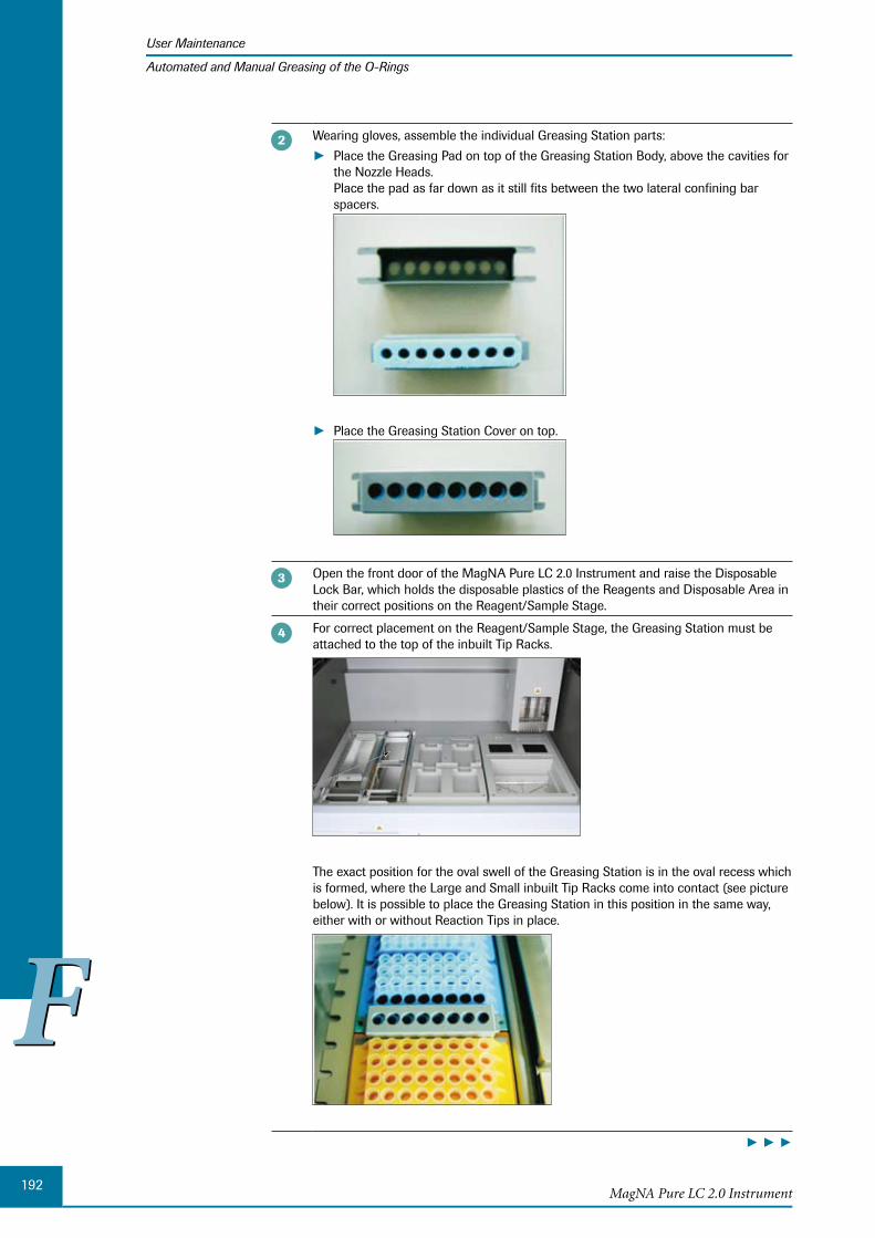
192
FFMagNA Pure LC 2.0 Instrument
User Maintenance
Automated and Manual Greasing of the O-Rings
Wearing gloves, assemble the individual Greasing Station parts:
Place the Greasing Pad on top of the Greasing Station Body, above the cavities for ►the Nozzle Heads. Place the pad as far down as it still fits between the two lateral confining bar spacers.
Place the Greasing Station Cover on top. ►
Open the front door of the MagNA Pure LC 2.0 Instrument and raise the Disposable Lock Bar, which holds the disposable plastics of the Reagents and Disposable Area in their correct positions on the Reagent/Sample Stage.
For correct placement on the Reagent/Sample Stage, the Greasing Station must be attached to the top of the inbuilt Tip Racks.
The exact position for the oval swell of the Greasing Station is in the oval recess which is formed, where the Large and Small inbuilt Tip Racks come into contact (see picture below). It is possible to place the Greasing Station in this position in the same way, either with or without Reaction Tips in place.
► ► ►

193
FFMaintenance
User Maintenance
Automated and Manual Greasing of the O-Rings
Close the Disposable Lock Bar and the front door of the MagNA Pure LC 2.0 Instru-ment.
■
To start automated greasing:
On the Maintenance sub-tab, select Automated Greasing.
The following request is displayed:
Select OK, to confirm that no purification run is currently active and that the Greasing Station is set correctly on the Reagent/Sample Stage.
The Nozzle Head moves from the Home position to the position of the Greasing Sta-tion and lowers the pipet Nozzles into the Greasing Station. The Nozzle Head will move around in the Greasing Station, thereby, automatically greasing the O-Rings.
After the O-Rings have been greased, the Nozzle Head moves back to the Home posi-tion.
Select OK, to confirm the Completed message, which is displayed when the automated greasing procedure is completed. The MagNA Pure LC 2.0 Instrument is ready for use.
■
1.1.2 Manual Greasing
The MagNA Pure LC O-Ring Maintenance Kit (Cat. No. 03 561 429 001) is used for man-ual greasing.
MagNA Pure LC O-Ring Maintenance Kit
The MagNA Pure LC O-Ring Maintenance Kit provides:
12 sets of exchange O-Rings ►
1 vial of Grease, which is optimally suited to the demands of the MagNA Pure LC 2.0 ►Instrument.
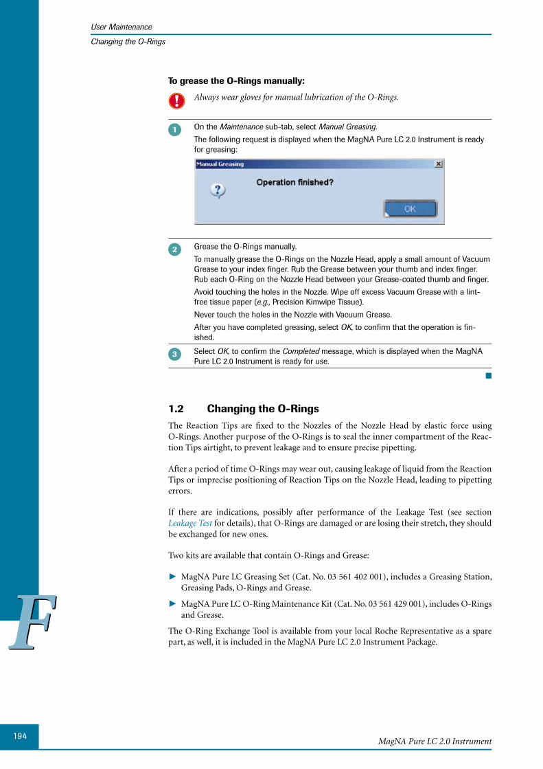
194
FFMagNA Pure LC 2.0 Instrument
User Maintenance
Changing the O-Rings
To grease the O-Rings manually:
Always wear gloves for manual lubrication of the O-Rings.
On the Maintenance sub-tab, select Manual Greasing.
The following request is displayed when the MagNA Pure LC 2.0 Instrument is ready for greasing:
Grease the O-Rings manually.
To manually grease the O-Rings on the Nozzle Head, apply a small amount of Vacuum Grease to your index finger. Rub the Grease between your thumb and index finger. Rub each O-Ring on the Nozzle Head between your Grease-coated thumb and finger.
Avoid touching the holes in the Nozzle. Wipe off excess Vacuum Grease with a lint-free tissue paper (e.g., Precision Kimwipe Tissue).
Never touch the holes in the Nozzle with Vacuum Grease.
After you have completed greasing, select OK, to confirm that the operation is fin-ished.
Select OK, to confirm the Completed message, which is displayed when the MagNA Pure LC 2.0 Instrument is ready for use.
■
1.2 Changing the O-RingsThe Reaction Tips are fixed to the Nozzles of the Nozzle Head by elastic force using O-Rings. Another purpose of the O-Rings is to seal the inner compartment of the Reac-tion Tips airtight, to prevent leakage and to ensure precise pipetting.
After a period of time O-Rings may wear out, causing leakage of liquid from the Reaction Tips or imprecise positioning of Reaction Tips on the Nozzle Head, leading to pipetting errors.
If there are indications, possibly after performance of the Leakage Test (see section Leakage Test for details), that O-Rings are damaged or are losing their stretch, they should be exchanged for new ones.
Two kits are available that contain O-Rings and Grease:
MagNA Pure LC Greasing Set (Cat. No. 03 561 402 001), includes a Greasing Station, ►Greasing Pads, O-Rings and Grease.
MagNA Pure LC O-Ring Maintenance Kit (Cat. No. 03 561 429 001), includes O-Rings ►and Grease.
The O-Ring Exchange Tool is available from your local Roche Representative as a spare part, as well, it is included in the MagNA Pure LC 2.0 Instrument Package.

195
FFMaintenance
User Maintenance
Changing the O-Rings
The O-Ring Exchange Tool
The O-Ring Exchange Tool can be closed and opened like forceps.
Ensure that the O-Ring Exchange Tool is clean prior to using. In particular, ensure that the pin that is inserted into the Nozzle Head is clean and free of Grease.

196
FFMagNA Pure LC 2.0 Instrument
User Maintenance
Changing the O-Rings
It is recommended to change the O-Rings at least after every 50 purification runs. The Roche service engineer can set this time interval in the Maintenance Reminder func-tion. For details, see section Service Reminders. You will then automatically be reminded to change the O-Rings.
It is very important that the Nozzle Head with O-Rings attached is not cleaned using bleach or ethanol. These reagents will remove Grease from the O-Rings and most probably even from within the O-Ring material, which in turn will lead to enhanced deterioration of the O-Rings. Do not clean the Nozzle Head with these reagents, when the O-Rings are attached. For further information on cleaning the outer surface of the Nozzle Head, see section Decontamination.
To remove an O-Ring from the Nozzle:
On the Maintenance sub-tab, select Change O-Ring.
The Robotic Arm moves to a position above the front Processing Cartridge positions.
Introduce the pin of the O-Ring Exchange Tool into the hole of a Nozzle:
Insert the pin as far as possible into the Nozzle hole.
By keeping the position of the pin, move the O-Ring pusher sideways until it is inserted into the Nozzle groove.
► ► ►
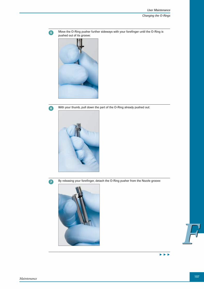
197
FFMaintenance
User Maintenance
Changing the O-Rings
Move the O-Ring pusher further sideways with your forefinger until the O-Ring is pushed out of its groove:
With your thumb, pull down the part of the O-Ring already pushed out:
By releasing your forefinger, detach the O-Ring pusher from the Nozzle groove:
► ► ►

198
FFMagNA Pure LC 2.0 Instrument
User Maintenance
Changing the O-Rings
Remove the O-Ring from the Nozzle by holding it with your thumb and pulling the O-Ring Exchange Tool downward:
The O-Ring is now removed from the Nozzle.
■
To correctly lubricate the new O-Ring:
To ensure correct Reaction Tip pick up and alignment, it is essential to lubricate the new O-Rings, before placing them on the pipet Nozzles. Furthermore, lubricating the O-Rings prevents them from deterioration, such as cracking. The use of a special High Vacuum Grease, which is included in the MagNA Pure LC Greasing Set (Cat. No. 03 561 402 001) and the MagNA Pure LC O-Ring Maintenance Kit (Cat. No. 03 561 429 001), is recom-mended.
Apply a small bit of Vacuum Grease to index finger, rub between thumb and index finger.
Rub new O-Ring between thumb and index finger. A small amount of excess Vacuum Grease on the O-Ring is acceptable during installation of new O-Rings.
Install the lubricated O-Ring on the pipet Nozzle using the O-Ring Exchange Tool, f ollowing the instructions below.
After the O-Ring is installed, wipe off excess Vacuum Grease with a Kimwipe (labora-tory tissue).
■

199
FFMaintenance
User Maintenance
Changing the O-Rings
To insert the new O-Ring:
Place a new, lubricated O-Ring on the shaft of the O-Ring Exchange Tool. Ensure that the O-Ring Exchange Tool is clean and that there is no Grease on the pin when it is inserted into the Nozzle hole.
Insert the pin of the O-Ring Exchange Tool as far as possible into the Nozzle hole:
By using your thumb and forefinger, hold the O-Ring and move it up along the shaft. Keep moving the O-Ring up until it is inserted into the Nozzle groove.
■
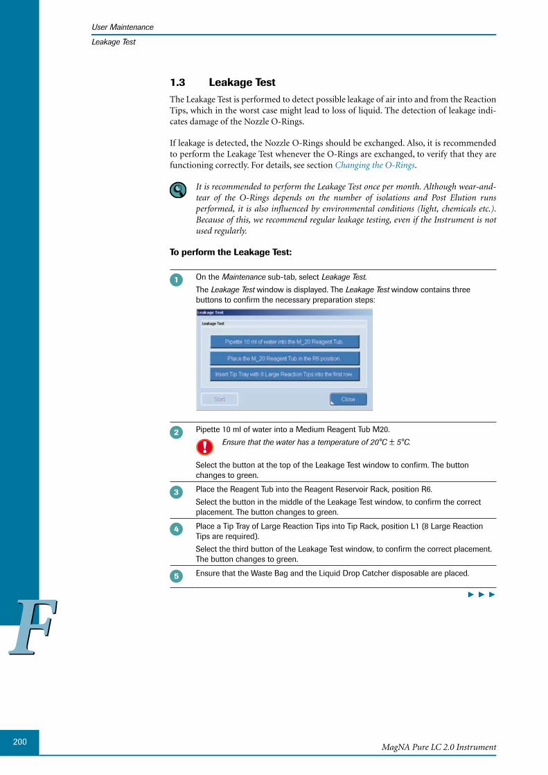
200
FFMagNA Pure LC 2.0 Instrument
User Maintenance
Leakage Test
1.3 Leakage TestThe Leakage Test is performed to detect possible leakage of air into and from the Reaction Tips, which in the worst case might lead to loss of liquid. The detection of leakage indi-cates damage of the Nozzle O-Rings.
If leakage is detected, the Nozzle O-Rings should be exchanged. Also, it is recommended to perform the Leakage Test whenever the O-Rings are exchanged, to verify that they are functioning correctly. For details, see section Changing the O-Rings.
It is recommended to perform the Leakage Test once per month. Although wear-and-tear of the O-Rings depends on the number of isolations and Post Elution runs p erformed, it is also influenced by environmental conditions (light, chemicals etc.). Because of this, we recommend regular leakage testing, even if the Instrument is not used regularly.
To perform the Leakage Test:
On the Maintenance sub-tab, select Leakage Test.
The Leakage Test window is displayed. The Leakage Test window contains three buttons to confirm the necessary preparation steps:
Pipette 10 ml of water into a Medium Reagent Tub M20.
Ensure that the water has a temperature of 20°C ± 5°C.
Select the button at the top of the Leakage Test window to confirm. The button changes to green.
Place the Reagent Tub into the Reagent Reservoir Rack, position R6.
Select the button in the middle of the Leakage Test window, to confirm the correct placement. The button changes to green.
Place a Tip Tray of Large Reaction Tips into Tip Rack, position L1 (8 Large Reaction Tips are required).
Select the third button of the Leakage Test window, to confirm the correct placement. The button changes to green.
Ensure that the Waste Bag and the Liquid Drop Catcher disposable are placed.
► ► ►
201
FFMaintenance
User Maintenance
Leakage Test
Select Start on the Leakage Test window, to start the Leakage Test.
The ‘Start’ button is disabled until all buttons in the ‘Leakage Test’ window are confirmed.
After the start of the run, the Robotic Arm picks up the Reaction Tips and moves ►to the Reagent Reservoir Rack, position R6 to aspirate 1 ml of water plus an additional 100 µl of air.
The Nozzle Head moves to a position at which the water line within the Reaction ►Tips, is in line with the upper rim of the Magnetic Plate behind the tips.
The Nozzle Head remains in this position for 10 min. ►It is now possible to open the Instrument Door, which improves observation of the liquid level within the Reaction Tips.
During the processing of the Leakage Test protocol, a window shows the remain-ing time.
To recognize possible leakage, watch the waterline inside the tips:
A waterline constant over all tips will tell you that no leakage has occurred. ►If you observe different levels of waterlines from Reaction Tip to Reaction Tip, ►leakage has occurred.
A difference between the levels of the waterlines of up to 4 mm can be tolerated and exchange of the O-Rings is not necessary.
After 10 min, you are requested to confirm your observations:
Select ► Leakage Test Passed, if you observed no leakage and then Close. The state of the Instrument is set to Ready and you can continue working.
Select ► Leakage Test Failed, if you observed leakage and then Close. The state of the Instrument is set to Leakage Test Failed. This state does not allow runs and lasts until an exchange of the O-Rings has been performed or the Leakage Test has been repeated with the result Leakage Test Passed. In this case, in the Status Bar, the status Leakage Test Failed is shown and the Ordering and Stage Setup sub-tabs are disabled.
The water is then dispensed back into the Medium Reagent Tub M20 and the Reac-tion Tips are discarded.
If you stop the Leakage Test prior to the end of the 10 min, you must discard the Reaction Tips afterwards: Select ‘Tip Discard’ on the ‘Maintenance’ sub-tab. Otherwise the water contained in the Reaction Tips could be spilled inside the Instrument during the initialization process, proceeding the following run.
■
202
FFMagNA Pure LC 2.0 Instrument
User Maintenance
Decontamination
1.4 Decontamination
General Workflow for Decontaminating the MagNA Pure LC 2.0 1.4.1 Instrument
The workflow described below is performed after each sample purification or liquid- handling run.
Caution
Be careful not to get disinfectant/decontamination reagent on the electrical (such as wiring) and optical components or on the mechanical parts. Also, remember that some Instrument parts have sharp corners and edges; to prevent injury, use less force while wiping these areas.
After such runs, remove and dispose
All leftover isolation reagents ►Waste Bottle (if using the Liquid Waste Discard function) ►The used Liquid Drop Catcher ►All other disposable plastics ► Handle waste according to national regulations (e.g., autoclave waste before
disposing).
Soak the Tip Waste Slide and the Liquid Waste Funnel in a tub with water that con-tains a suitable disinfection/decontamination reagent. Ensure that all Magnetic Glass Particles are removed completely from the Tip Waste Slide (e.g., by brushing).
If necessary repeat this step.
Finally, rinse the Tip Waste Slide and the Liquid Waste Funnel with distilled water.
Clean MagNA Pure LC Accessories such as Cooling Blocks, Waste Bottle Tray and Reagent Reservoir Rack with a suitable disinfection/decontamination reagent.
You may remove these accessories from the Instrument before disinfecting/decon-taminating them.
Wipe the front surface and underneath the Magnetic Plate with a soft lint-free cloth that has been dampened with 70% ethanol.
Clean all accessible surfaces on the Instrument (stage plate, side walls, empty ac-cessory compartments) with a suitable disinfection/decontamination reagent. If any Instrument surface contains a dried residue from a reagent spill, rehydrate the spilled material with a mixture of warm water and disinfection/decontamination reagent before cleaning the surface.
If using 10% (v/v) bleach solution (0.5% sodium hypochlorite), wipe the Reagent/Sample Stage with the reagent and let it sit for 10 min. Remove the bleach completely by wiping the Instrument surface with 70% ethanol, followed by pure water. Ventilate the Instrument for at least 1 hour.
Commercial liquid household bleach typically contains sodium hypochlorite at a concentration of 5.25%. A 1 in 10 dilution of typically household bleach will produce a 0.5% sodium hypochlorite solution.
After the cleaning procedure, place the Tip Waste Slide, Liquid Waste Funnel, Waste Bottle Tray and Waste Bottle, if necessary back in the Instrument and turn the UV lamp on for a minimum of 8 hours.
■

203
FFMaintenance
User Maintenance
Decontamination
1.4.2 Decontaminating the Instrument
At the end of each working day on the MagNA Pure LC 2.0 Instrument, the Instrument should be decontaminated from nucleic acids using the built-in UV lamp. See section D econtaminating the Inner Parts of the MagNA Pure LC 2.0 Instrument for details of use.
For safety reasons it is recommended to decontaminate the surface of the Instrument and the accessories additionally, by wiping them with decontaminating reagents that destroy any nucleic acids or DNases and RNases. Also decontaminate the work area where the manual handling steps are performed.
When cleaning and decontaminating the Instrument, use gloves and safety glasses at all times; always wear a laboratory coat. In addition, take all normal laboratory pre-cautions for handling chemical reagents.
Before cleaning, turn the Instrument off and unplug it. Let the surfaces around the heating block cool to room temperature before starting the cleaning procedure.
Do not spray any reagent directly into the Instrument because reagent aerosols may damage electronic or optical components. Instead, wipe Instrument parts and surfaces with a cloth that has been dampened with reagent.
Workflow for disinfection/decontamination always has two steps:
Disinfection (cleaning and disinfection) ►
Decontamination (removal of DNA/RNA and nucleases) ►
For decontamination, either bleach (0.5% solution of sodium hypochlorite) or the follow-ing commercially available reagents may be used (follow the working procedures given by the respective manufacturer). Use of bleach is an exception, since bleach disinfects and decontaminates simultaneously.
Decontamination Reagents
Reagent Description Manufacturer Order Number
LTK-008 Ready to use reagent, especially designed to remove contamination of DNA, RNA, DNase, RNase, bacteria and phages from work sur-faces.
Biodelta GmbH Am Mittelbach 11 32584 Löhne Germany Phone: +49-5731-981-6201 Fax: +49-5731-86-0190 Email: [email protected] or [email protected]
200-000
DNAZap™ Completely degrades contaminating DNA and RNA at the level of PCR sensitivity
Ambion Inc. 2130 Woodward Austin, Texas, USA
http://www.ambion.com/ catalog/CatNum.php?9890
AM9890
RNase Zap® Completely removes RNase contamination
Ambion Inc. 2130 Woodward Austin, Texas, USA
http://www.ambion.com/ catalog/CatNum.php?9780
AM9780
AM9782
AM9784
204
FFMagNA Pure LC 2.0 Instrument
User Maintenance
Decontamination
Never clean the MagNA Pure LC Cooling Blocks in a dishwasher.
If infectious sample material is used, additional safety measures must be taken by using disinfection reagents.
The above mentioned decontaminating reagents are not sufficient to disinfect the sur-face of the Instrument or accessories.
Decontaminating the Nozzle Head1.4.3
For disinfection and decontamination of the outer surface of the Nozzle Head, follow this procedure:
First remove the O-Rings with the O-Ring Exchange Tool and throw them away.
Clean the outside surfaces of the Nozzles with a suitable disinfection/decontamination reagent.
Avoid getting liquid inside the Nozzles, since this could reduce pipetting precision.
Remove all chemicals with PCR-grade water, then dry the surface with a lint-free tissue paper. Otherwise, residual chemicals may adversely affect the O-Rings.
Put new O-Rings on the Nozzles (do not forget to manually grease the O-Rings during this process) as described in section Changing the O-Rings.
■
1.4.4 D econtaminating the Inner Parts of the MagNA Pure LC 2.0 Instrument
The MagNA Pure LC 2.0 Instrument includes a UV lamp (emission 254 nm) for decon-tamination of the Reagent/Sample Stage from nucleic acids. The operation of this UV lamp is regulated by the user via the MagNA Pure LC 2.0 Software.
It is recommended to decontaminate the Instrument from nucleic acids at least at the end of each work day.
Areas of the Instrument directly exposed to the UV light, e.g., the center of the Reagent/Sample Stage are sufficiently decontaminated after 8 hrs. Areas further away from the UV light or located in the UV “shadow” (e.g., the Magnetic Plate or corners of the Instrument Housing) might not be sufficiently decontaminated after 8 hrs.
Because of this, if assuming a severe contamination of the Instrument with nucleic acids, additionally wipe the Instrument areas and accessories with a decontamination reagent, prior to Decontamination (see section Decontaminating the Instrument).
Be aware that decontamination using the built-in UV light is not sufficient to destroy DNases and/or RNases or to disinfect the Instrument after processing of infectious sample material. For removal of DNases and/or RNases, use LTK-008 or RNase ZAP (see section Decontaminating the Instrument for details). For disinfection use a suit-able disinfection reagent (e.g., Microzid or Kohrsolin ID).
Do not spray any reagent directly into the Instrument, because reagent aerosols may damage electronic components or optical devices might be damaged.
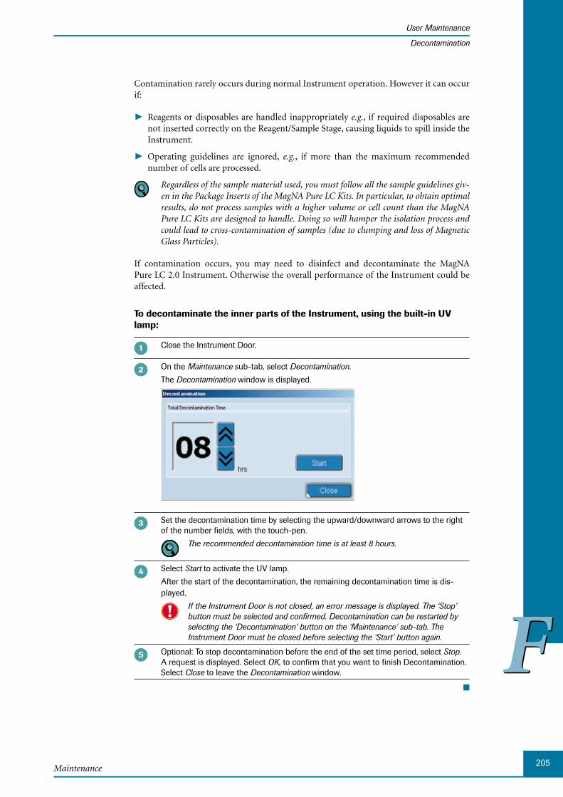
205
FFMaintenance
User Maintenance
Decontamination
Contamination rarely occurs during normal Instrument operation. However it can occur if:
Reagents or disposables are handled inappropriately ► e.g., if required disposables are not inserted correctly on the Reagent/Sample Stage, causing liquids to spill inside the Instrument.
Operating guidelines are ignored, ► e.g., if more than the maximum recommended number of cells are processed.
Regardless of the sample material used, you must follow all the sample guidelines giv-en in the Package Inserts of the MagNA Pure LC Kits. In particular, to obtain optimal results, do not process samples with a higher volume or cell count than the MagNA Pure LC Kits are designed to handle. Doing so will hamper the isolation process and could lead to cross-contamination of samples (due to clumping and loss of Magnetic Glass Particles).
If contamination occurs, you may need to disinfect and decontaminate the MagNA Pure LC 2.0 Instrument. Otherwise the overall performance of the Instrument could be affected.
To decontaminate the inner parts of the Instrument, using the built-in UV lamp:
Close the Instrument Door.
On the Maintenance sub-tab, select Decontamination.
The Decontamination window is displayed.
Set the decontamination time by selecting the upward/downward arrows to the right of the number fields, with the touch-pen.
The recommended decontamination time is at least 8 hours.
Select Start to activate the UV lamp.
After the start of the decontamination, the remaining decontamination time is dis-played.
If the Instrument Door is not closed, an error message is displayed. The ‘Stop’ button must be selected and confirmed. Decontamination can be restarted by selecting the ‘Decontamination’ button on the ‘Maintenance’ sub-tab. The Instrument Door must be closed before selecting the ‘Start’ button again.
Optional: To stop decontamination before the end of the set time period, select Stop. A request is displayed. Select OK, to confirm that you want to finish Decontamination. Select Close to leave the Decontamination window.
■
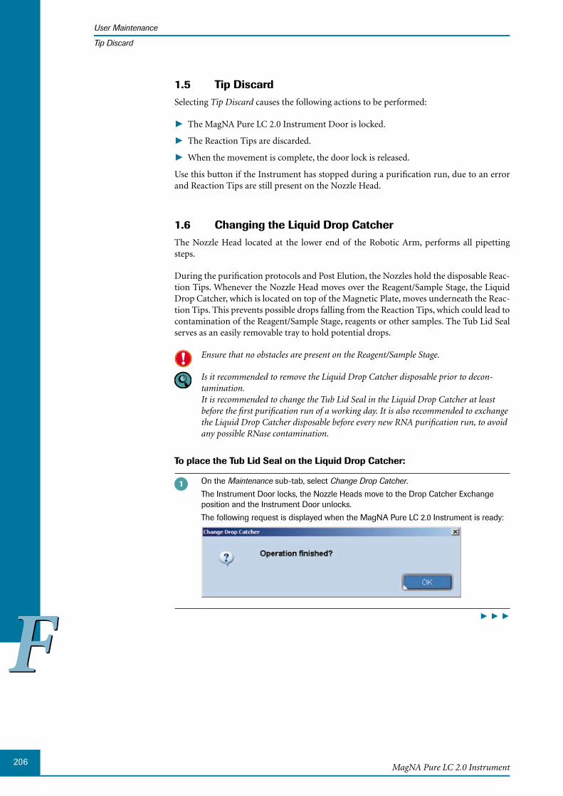
206
FFMagNA Pure LC 2.0 Instrument
User Maintenance
Tip Discard
Tip Discard1.5 Selecting Tip Discard causes the following actions to be performed:
The MagNA Pure LC 2.0 Instrument Door is locked. ►
The Reaction Tips are discarded. ►
When the movement is complete, the door lock is released. ►
Use this button if the Instrument has stopped during a purification run, due to an error and Reaction Tips are still present on the Nozzle Head.
1.6 Changing the Liquid Drop CatcherThe Nozzle Head located at the lower end of the Robotic Arm, performs all pipetting steps.
During the purification protocols and Post Elution, the Nozzles hold the disposable Reac-tion Tips. Whenever the Nozzle Head moves over the Reagent/Sample Stage, the Liquid Drop Catcher, which is located on top of the Magnetic Plate, moves underneath the Reac-tion Tips. This prevents possible drops falling from the Reaction Tips, which could lead to contamination of the Reagent/Sample Stage, reagents or other samples. The Tub Lid Seal serves as an easily removable tray to hold potential drops.
Ensure that no obstacles are present on the Reagent/Sample Stage.
Is it recommended to remove the Liquid Drop Catcher disposable prior to decon-tamination. It is recommended to change the Tub Lid Seal in the Liquid Drop Catcher at least before the first purification run of a working day. It is also recommended to exchange the Liquid Drop Catcher disposable before every new RNA purification run, to avoid any possible RNase contamination.
To place the Tub Lid Seal on the Liquid Drop Catcher:
On the Maintenance sub-tab, select Change Drop Catcher.
The Instrument Door locks, the Nozzle Heads move to the Drop Catcher Exchange position and the Instrument Door unlocks.
The following request is displayed when the MagNA Pure LC 2.0 Instrument is ready:
► ► ►

207
FFMaintenance
User Maintenance
Changing the Liquid Drop Catcher
With gloved fingers or clean plastic forceps, slide a Tub Lid Seal into the groove of the Liquid Drop Catcher from the right:
Continue pushing until the left side of the Tub Lid Seal reaches the end of the Liquid Drop Catcher groove.
Left side ofTub Lid Seal
End of groove
While sliding the Tub Lid Seal into the Liquid Drop Catcher groove, it may ride upward, out of the groove. Once the left side of the Tub Lid Seal reaches the end of the groove, the Tub Lid Seal falls automatically into the correct position.
After placement of the Tub Lid Seal, close the Instrument Door and select OK, to c onfirm the Operation finished message.
Select OK, to confirm the Completed message, which is displayed when the MagNA Pure LC 2.0 Instrument is ready for use.
Select Home in the Maintenance sub-tab.
The Instrument Door locks and the Nozzle Heads moves to the Home position.
After the Robotic Arm moves to the Home position, the Instrument Door will be unlocked.
■

208
FFMagNA Pure LC 2.0 Instrument
User Maintenance
Changing the Liquid Drop Catcher
To remove the Tub Lid Seal from the Liquid Drop Catcher:
On the Maintenance sub-tab, select Change Drop Catcher.
The Instrument Door locks, the Nozzle Heads move to the Drop Catcher Exchange position and the Instrument Door unlocks.
The following request is displayed when the MagNA Pure LC 2.0 Instrument is ready:
With gloved fingers or clean plastic forceps, start pushing the Tub Lid Seal from the left side of the Liquid Drop Catcher groove.
Continue pushing the Tub Lid Seal from the left side with a clean Large Reaction Tip or clean plastic forceps, until the Tub Lid Seal can be reached with gloved fingers:
Forceps or large tip
► ► ►
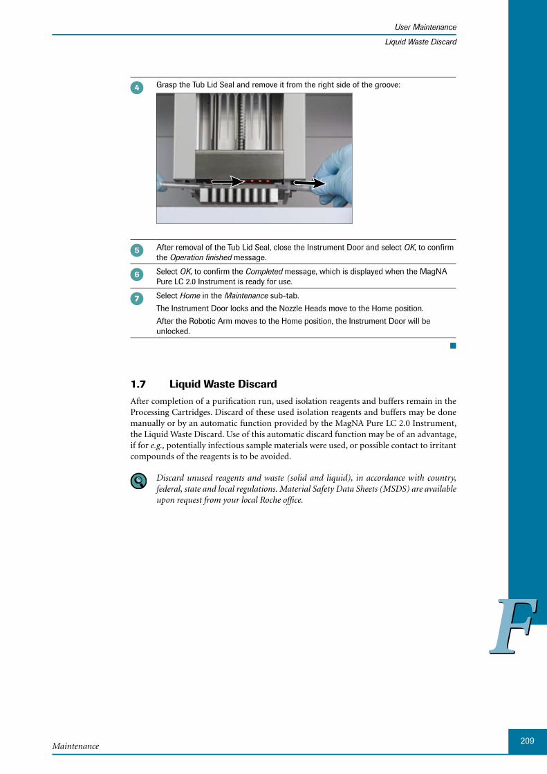
209
FFMaintenance
User Maintenance
Liquid Waste Discard
Grasp the Tub Lid Seal and remove it from the right side of the groove:
After removal of the Tub Lid Seal, close the Instrument Door and select OK, to confirm the Operation finished message.
Select OK, to confirm the Completed message, which is displayed when the MagNA Pure LC 2.0 Instrument is ready for use.
Select Home in the Maintenance sub-tab.
The Instrument Door locks and the Nozzle Heads move to the Home position.
After the Robotic Arm moves to the Home position, the Instrument Door will be unlocked.
■
1.7 Liquid Waste DiscardAfter completion of a purification run, used isolation reagents and buffers remain in the Processing Cartridges. Discard of these used isolation reagents and buffers may be done manually or by an automatic function provided by the MagNA Pure LC 2.0 Instrument, the Liquid Waste Discard. Use of this automatic discard function may be of an advantage, if for e.g., potentially infectious sample materials were used, or possible contact to irritant compounds of the reagents is to be avoided.
Discard unused reagents and waste (solid and liquid), in accordance with country, federal, state and local regulations. Material Safety Data Sheets (MSDS) are available upon request from your local Roche office.
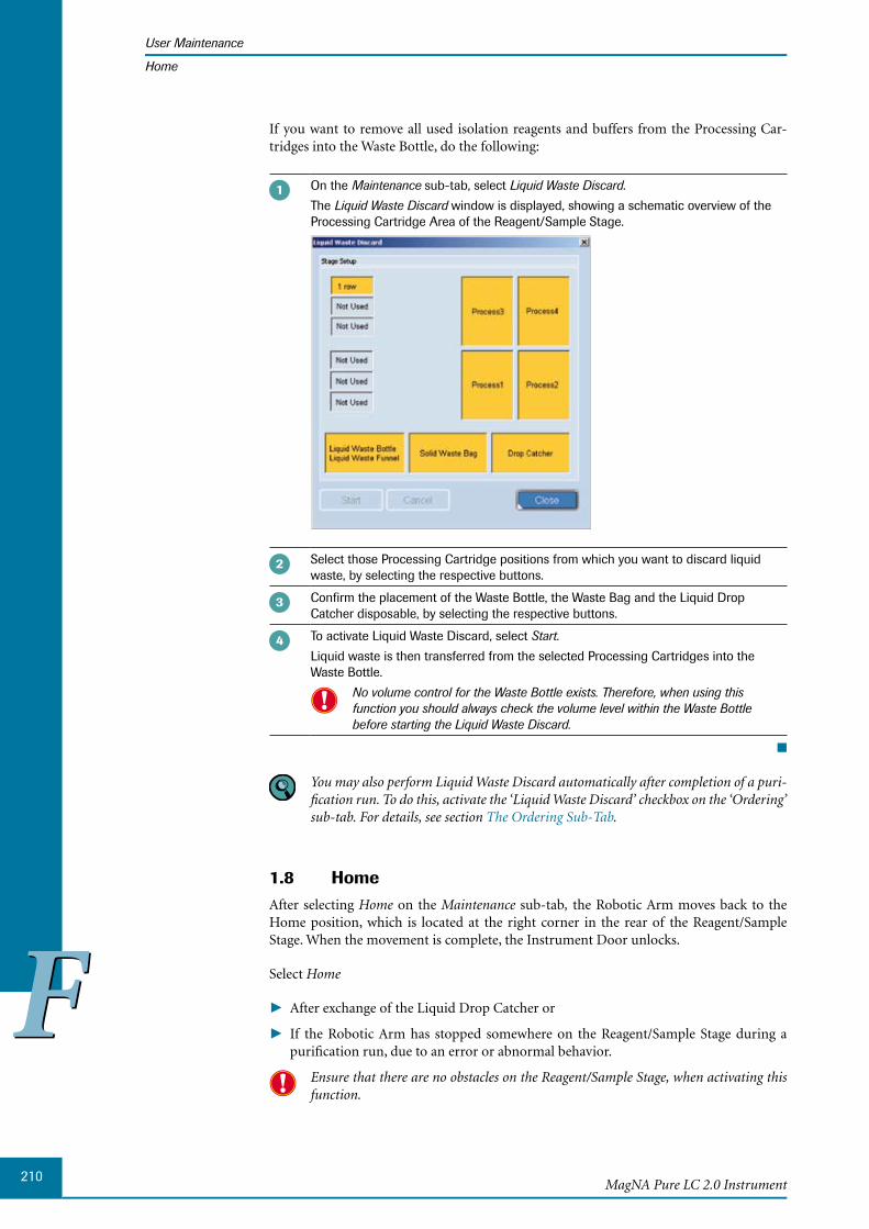
210
FFMagNA Pure LC 2.0 Instrument
User Maintenance
Home
If you want to remove all used isolation reagents and buffers from the Processing Car-tridges into the Waste Bottle, do the following:
On the Maintenance sub-tab, select Liquid Waste Discard.
The Liquid Waste Discard window is displayed, showing a schematic overview of the Processing Cartridge Area of the Reagent/Sample Stage.
Select those Processing Cartridge positions from which you want to discard liquid waste, by selecting the respective buttons.
Confirm the placement of the Waste Bottle, the Waste Bag and the Liquid Drop Catcher disposable, by selecting the respective buttons.
To activate Liquid Waste Discard, select Start.
Liquid waste is then transferred from the selected Processing Cartridges into the Waste Bottle.
No volume control for the Waste Bottle exists. Therefore, when using this function you should always check the volume level within the Waste Bottle before starting the Liquid Waste Discard.
■
You may also perform Liquid Waste Discard automatically after completion of a puri-fication run. To do this, activate the ‘Liquid Waste Discard’ checkbox on the ‘Ordering’ sub-tab. For details, see section The Ordering Sub-Tab.
1.8 HomeAfter selecting Home on the Maintenance sub-tab, the Robotic Arm moves back to the Home position, which is located at the right corner in the rear of the Reagent/Sample Stage. When the movement is complete, the Instrument Door unlocks.
Select Home
After ► exchange of the Liquid Drop Catcher or
If ► the Robotic Arm has stopped somewhere on the Reagent/Sample Stage during a purification run, due to an error or abnormal behavior.
Ensure that there are no obstacles on the Reagent/Sample Stage, when activating this function.
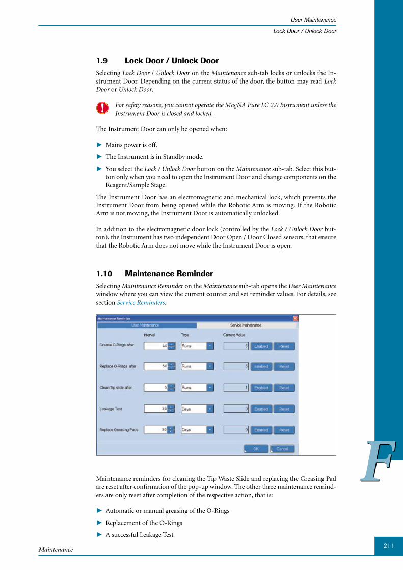
211
FFMaintenance
User Maintenance
Lock Door / Unlock Door
1.9 Lock Door / Unlock DoorSelecting Lock Door / Unlock Door on the Maintenance sub-tab locks or unlocks the In-strument Door. Depending on the current status of the door, the button may read Lock Door or Unlock Door.
For safety reasons, you cannot operate the MagNA Pure LC 2.0 Instrument unless the Instrument Door is closed and locked.
The Instrument Door can only be opened when:
Mains power is off. ►
The Instrument is in Standby mode. ►
You select the ► Lock / Unlock Door button on the Maintenance sub-tab. Select this but-ton only when you need to open the Instrument Door and change components on the Reagent/Sample Stage.
The Instrument Door has an electromagnetic and mechanical lock, which prevents the Instrument Door from being opened while the Robotic Arm is moving. If the Robotic Arm is not moving, the Instrument Door is automatically unlocked.
In addition to the electromagnetic door lock (controlled by the Lock / Unlock Door but-ton), the Instrument has two independent Door Open / Door Closed sensors, that ensure that the Robotic Arm does not move while the Instrument Door is open.
1.10 Maintenance ReminderSelecting Maintenance Reminder on the Maintenance sub-tab opens the User Maintenance window where you can view the current counter and set reminder values. For details, see section Service Reminders.
Maintenance reminders for cleaning the Tip Waste Slide and replacing the Greasing Pad are reset after confirmation of the pop-up window. The other three maintenance remind-ers are only reset after completion of the respective action, that is:
A ► utomatic or manual greasing of the O-Rings
R ► eplacement of the O-Rings
A ► successful Leakage Test
212
FFMagNA Pure LC 2.0 Instrument
User Maintenance
Create Problem Report
1.11 Create Problem ReportFor troubleshooting by the Roche service engineer, you can export error messages and configuration files to a problem report.
The problem report is a zipped file containing log, configuration and version files.
To create a Problem Report:
Select the Create Problem Report button on the Maintenance sub-tab. This opens a file selection window, in which you can specify the location where the Problem Report files are to be saved.
Select the Save button, to compress the database file, ini files, log files and protocol files to a zip file and to save the zip file in the selected folder or on a USB stick or CD/DVD.
■

213
FFMaintenance
Service Maintenance
2 Service MaintenanceA Roche representative should perform the first Service Maintenance of the Instrument, one year after the Instrument is installed. Subsequently, this Service Maintenance should be performed annually.
Service Maintenance may only be performed by a Roche representative. Contact your local Roche representative for more details on country-specific service contracts.
Service Reminders
The MagNA Pure LC 2.0 Software has a Counter and Reminder function, which for e.g., counts the number of runs, number of hours of UV lamp usage and the number of hours of operation.
Your Roche representative is able to set the reminders based on these individual counters or on a fixed date e.g., to be reminded for the regular O-Ring or UV lamp exchange. If the counter reaches the set “Next Reminder” value, the reminder text defined is displayed on the screen.
To view the current counter and set reminder values, you can access the Maintenance Reminder window via the Maintenance Reminder button on the Maintenance sub-tab.
Reminder values in the ‘Maintenance Reminder’ window can be changed by Roche representatives only.

214
FFMagNA Pure LC 2.0 Instrument

Chapter G • Appendix
216MagNA Pure LC 2.0 Instrument
Table of Contents
GG G Appendix 217
1 Installed Purification Protocols ............................................................................................................217
2 Troubleshooting.............................................................................................................................................219
2.1 List of Error Codes ...........................................................................................................................................2192.2 Troubleshooting Guide ...................................................................................................................................231
3 Ordering Information ..................................................................................................................................237
4 Index .......................................................................................................................................239
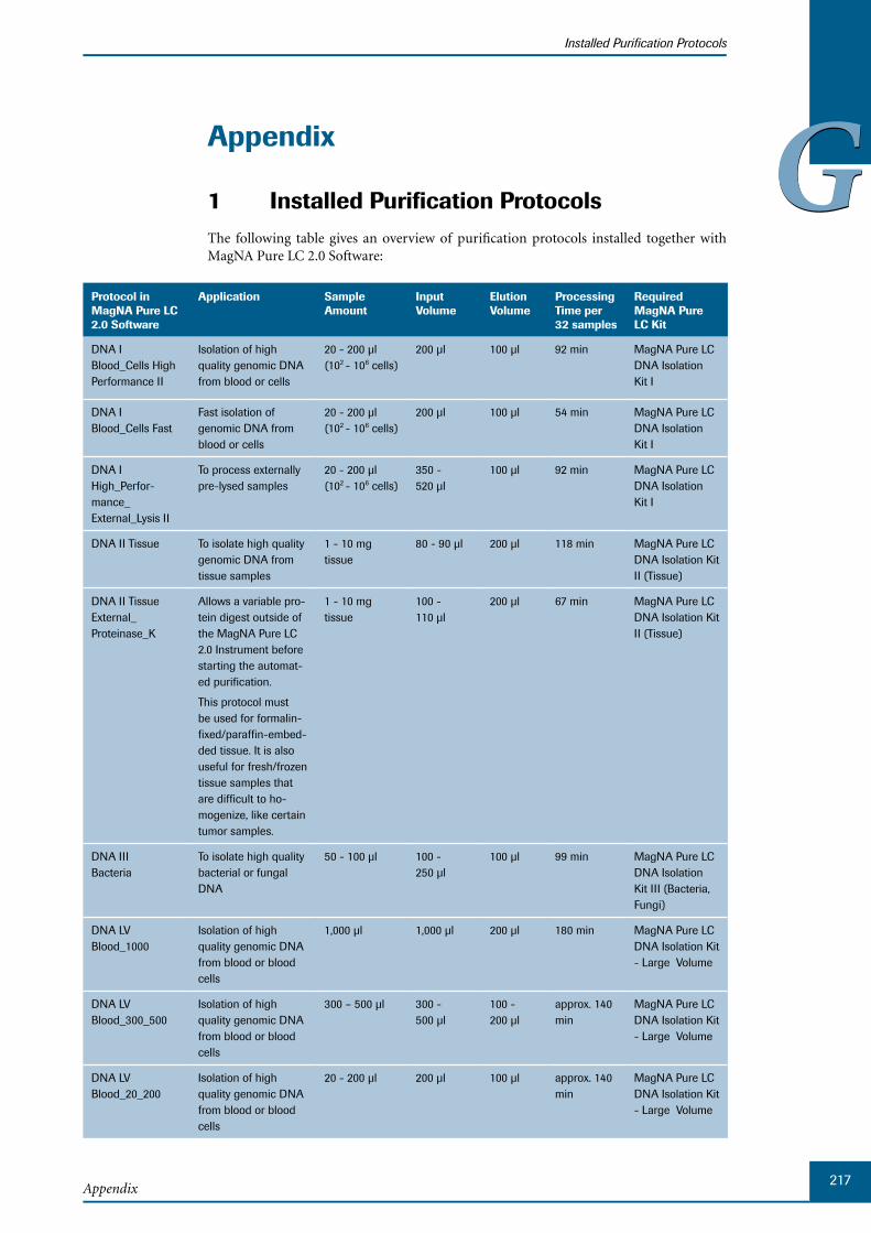
217Appendix
Installed Purification Protocols
GGAppendix
1 Installed Purification ProtocolsThe following table gives an overview of purification protocols installed together with MagNA Pure LC 2.0 Software:
Protocol in MagNA Pure LC 2.0 Software
Application Sample Amount
Input Volume
Elution Volume
Processing Time per 32 samples
Required MagNA Pure LC Kit
DNA I Blood_Cells High Performance II
Isolation of high quality genomic DNA from blood or cells
20 - 200 µl (102 - 106 cells)
200 µl 100 µl 92 min MagNA Pure LC DNA Isolation Kit I
DNA I Blood_Cells Fast
Fast isolation of genomic DNA from blood or cells
20 - 200 µl (102 - 106 cells)
200 µl 100 µl 54 min MagNA Pure LC DNA Isolation Kit I
DNA I High_Perfor-mance_ External_Lysis II
To process externally pre-lysed samples
20 - 200 µl (102 - 106 cells)
350 - 520 µl
100 µl 92 min MagNA Pure LC DNA Isolation Kit I
DNA II Tissue To isolate high quality genomic DNA from tissue samples
1 - 10 mg tissue
80 - 90 µl 200 µl 118 min MagNA Pure LC DNA Isolation Kit II (Tissue)
DNA II Tissue External_Proteinase_K
Allows a variable pro-tein digest outside of the MagNA Pure LC 2.0 Instrument before starting the automat-ed purification.
This protocol must be used for formalin-fixed/paraffin-embed-ded tissue. It is also useful for fresh/frozen tissue samples that are difficult to ho-mogenize, like certain tumor samples.
1 - 10 mg tissue
100 - 110 µl
200 µl 67 min MagNA Pure LC DNA Isolation Kit II (Tissue)
DNA III Bacteria
To isolate high quality bacterial or fungal DNA
50 - 100 µl 100 - 250 µl
100 µl 99 min MagNA Pure LC DNA Isolation Kit III (Bacteria, Fungi)
DNA LV Blood_1000
Isolation of high quality genomic DNA from blood or blood cells
1,000 µl 1,000 µl 200 µl 180 min MagNA Pure LC DNA Isolation Kit - Large Volume
DNA LV Blood_300_500
Isolation of high quality genomic DNA from blood or blood cells
300 – 500 µl 300 - 500 µl
100 - 200 µl
approx. 140 min
MagNA Pure LC DNA Isolation Kit - Large Volume
DNA LV Blood_20_200
Isolation of high quality genomic DNA from blood or blood cells
20 - 200 µl 200 µl 100 µl approx. 140 min
MagNA Pure LC DNA Isolation Kit - Large Volume

218MagNA Pure LC 2.0 Instrument
Installed Purification Protocols
GG Protocol in MagNA Pure LC 2.0 Software
Application Sample Amount
Input Volume
Elution Volume
Processing Time per 32 samples
Required MagNA Pure LC Kit
DNA LV Cells Isolation of high qual-ity genomic DNA from cultured cells
Up to 5 × 10⁶ cells
100 µl 100 - 200 µl
140 min MagNA Pure LC DNA Isolation Kit - Large Volume
RNA HP Blood To isolate total RNA from blood and white blood cells
20 – 200 µl 200 µl 50 - 100 µl
83 min MagNA Pure LC RNA Isolation Kit - High Performance
RNA HP Cells To isolate high qual-ity total RNA from cultured cells
102 - 106 cells 200 µl 50 - 100 µl
87 min MagNA Pure LC RNA Isolation Kit - High Performance
RNA HP Blood_External_Lysis
To isolate high quality RNA from externally pre-lysed blood samples
20 - 100 µl 720 - 900 µl
50 - 100 µl
95 min MagNA Pure LC RNA Isolation Kit - High Performance
RNA III Tissue_Fresh-frozen
To isolate high quality RNA from tissue
1 - 10 mg 350 µl 50 - 100 µl
84 min MagNA Pure LC RNA Isolation Kit III (Tissue)
RNA III Tissue_Paraffin
To isolate RNA from paraffin-embedded tissue
350 µl 50 - 100 µl
122 min MagNA Pure LC RNA Isolation Kit III (Tissue)
Total NA Serum_Plasma_Blood
To isolate high quality total (viral) nucleic acid from blood, serum and plasma samples using a fixed elution volume
50 - 200 µl 200 µl 100 µl 90 min MagNA Pure LC Total Nucleic Acid Isolation Kit
Total NA Variable_ Elution_ Volume
To isolate high quality total (viral) nucleic acid from serum and plasma samples using a variable elution volume
50 - 200 µl 200 µl 50 - 100 µl
90 min MagNA Pure LC Total Nucleic Acid Isolation Kit
Total NA External_Lysis
To isolate high quality total (viral) nucleic acid from externally pre-lysed serum and plasma samples using a variable elution volume
50 - 200 µl 350 - 500 µl
50 - 100 µl
90 min MagNA Pure LC Total Nucleic Acid Isolation Kit
Total NA LV Serum_Plasma
To isolate high quality total (viral) nucleic acid from up to 1 ml of serum and plasma samples
200 - 1,000 µl
1,000 µl 50 - 100 µl
99 min MagNA Pure LC Total Nucleic Acid Isolation Kit – Large Volume
The major application for the “DNA I Blood_Cells Fast” protocol is Mutation Analysis where high yield and linear scalability of yield over the whole sample volume range is not required. The “DNA I Blood_Cells High Performance” protocol is recommended when you are looking for high yield and/or for linear scalability over the whole sample volume range, e.g., if you are performing quantitative PCR analysis.

219Appendix
Troubleshooting
List of Error Codes
GGTroubleshooting2 This section contains a List of Error Codes and a Troubleshooting Guide. If you can not solve the problem by following either of these, then please contact technical service. Any unauthorized modification of the MagNA Pure LC 2.0 Instrument and/or of the MagNA Pure LC 2.0 Software, results in the invalidity of the guarantee and service contract.
List of Error Codes2.1 When an error occurs, the MagNA Pure LC 2.0 Software indicates the nature of the error by the Error Code (corresponding to the ID column on the Messages tab) and the Error Level - Warning, Error, Fatal - (corresponding to the Priority column on the Messages tab). For detailed information, see section Displaying Messages.
Error List Messages
No. Error Code
ErrorLevel
Description in Message File (Message.ini)
Description
M101 1 F [Short Message]
Failed to Initialize BIOS ►[Long Message]
Software error: BIOS failed ►to initialize.
Hardware problem:
Contact technical service to call a ►Roche service engineer.
M102 2 F N/A
This error occurs prior to the Error Log starting up.
Hardware problem:
Contact technical service to call a ►Roche service engineer.
M103 3 - N/A
This error occurs prior to the Error Log starting up.
External Windows XP error:
Reboot system. ►
M104 4 - N/A
This error occurs prior to the Error Log starting up.
External Windows XP error:
Reboot system. ►
M105 5 - N/A
This error occurs prior to the Error Log starting up.
External Windows XP error:
Reboot system. ►
M106 6 - N/A
This error occurs prior to the Error Log starting up.
External Windows XP error:
Reboot system. ►
M107 7 F [Short Message]
Invalid script command. ►[Long Message]
Software error: The request- ►ed script command does not exist.
Internal software error:
Contact technical service. ►
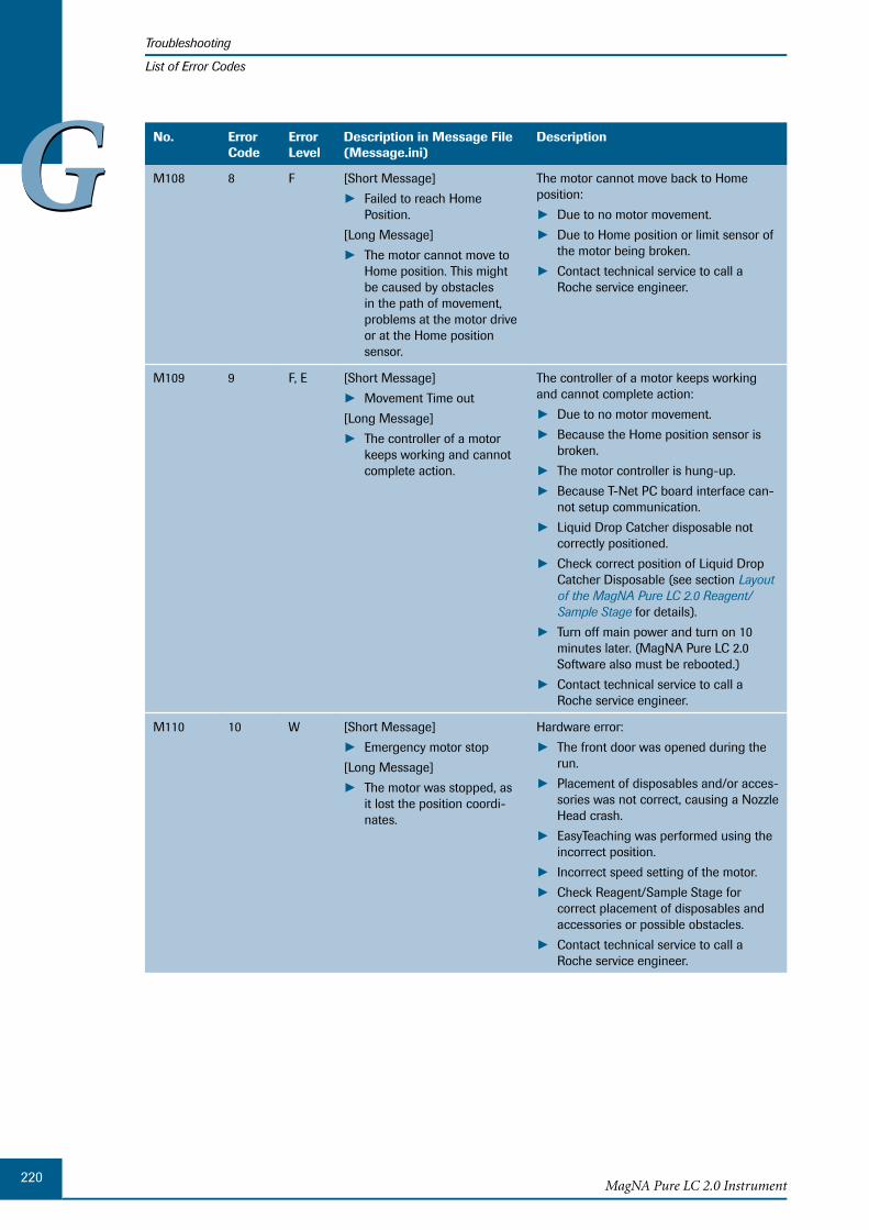
220MagNA Pure LC 2.0 Instrument
Troubleshooting
List of Error Codes
GG No. Error Code
ErrorLevel
Description in Message File (Message.ini)
Description
M108 8 F [Short Message]
Failed to reach Home ► Position.
[Long Message]
The motor cannot move to ►Home position. This might be caused by obstacles in the path of movement, problems at the motor drive or at the Home position sensor.
The motor cannot move back to Home position:
Due to no motor movement. ►Due to Home position or limit sensor of ►the motor being broken.
Contact technical service to call a ►Roche service engineer.
M109 9 F, E [Short Message]
Movement Time out ►[Long Message]
The controller of a motor ►keeps working and cannot complete action.
The controller of a motor keeps working and cannot complete action:
Due to no motor movement. ►Because the Home position sensor is ►broken.
The motor controller is hung-up. ►Because T-Net PC board interface can- ►not setup communication.
Liquid Drop Catcher disposable not ►correctly positioned.
Check correct position of Liquid Drop ►Catcher Disposable (see section Layout of the MagNA Pure LC 2.0 Reagent/Sample Stage for details).
Turn off main power and turn on 10 ►minutes later. (MagNA Pure LC 2.0 Software also must be rebooted.)
Contact technical service to call a ►Roche service engineer.
M110 10 W [Short Message]
Emergency motor stop ►[Long Message]
The motor was stopped, as ►it lost the position coordi-nates.
Hardware error:
The front door was opened during the ►run.
Placement of disposables and/or acces- ►sories was not correct, causing a Nozzle Head crash.
EasyTeaching was performed using the ►incorrect position.
Incorrect speed setting of the motor. ►Check Reagent/Sample Stage for ►correct placement of disposables and accessories or possible obstacles.
Contact technical service to call a ►Roche service engineer.
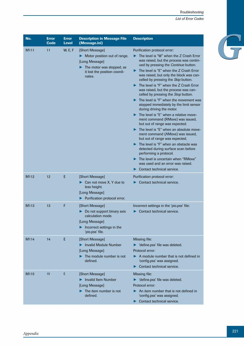
221Appendix
Troubleshooting
List of Error Codes
GGNo. Error Code
ErrorLevel
Description in Message File (Message.ini)
Description
M111 11 W, E, F [Short Message]
Motor position out of range. ►[Long Message]
The motor was stopped, as ►it lost the position coordi-nates.
Purification protocol error:
The level is “W” when the Z Crash Error ►was raised, but the process was contin-ued by pressing the Continue button.
The level is “E” when the Z Crash Error ►was raised, but only the block was can-celled by pressing the Skip button.
The level is “F” when the Z Crash Error ►was raised, but the process was can-celled by pressing the Stop button.
The level is “F” when the movement was ►stopped immediately by the limit sensor during driving the motor.
The level is “E” when a relative move- ►ment command (RMove) was issued, but out of range was expected.
The level is “E” when an absolute move- ►ment command (AMove) was issued, but out of range was expected.
The level is “F” when an obstacle was ►detected during surface scan before performing a protocol.
The level is uncertain when “RMove” ►was used and an error was raised.
Contact technical service. ►
M112 12 E [Short Message]
Can not move X, Y due to ►less height.
[Long Message]
Purification protocol error. ►
Purification protocol error:
Contact technical service. ►
M113 13 F [Short Message]
Do not support binary axis ►calculation mode.
[Long Message]
Incorrect settings in the ►‘pio.pss’ file.
Incorrect settings in the ‘pio.pss’ file:
Contact technical service. ►
M114 14 E [Short Message]
Invalid Module Number ►[Long Message]
The module number is not ►defined.
Missing file:
‘define.pss’ file was deleted. ►Protocol error:
A module number that is not defined in ►‘config.pss’ was assigned.
Contact technical service. ►
M115 15 E [Short Message]
Invalid Item Number ►[Long Message]
The item number is not ►defined.
Missing file:
‘define.pss’ file was deleted. ►Protocol error:
An item number that is not defined in ►‘config.pss’ was assigned.
Contact technical service. ►
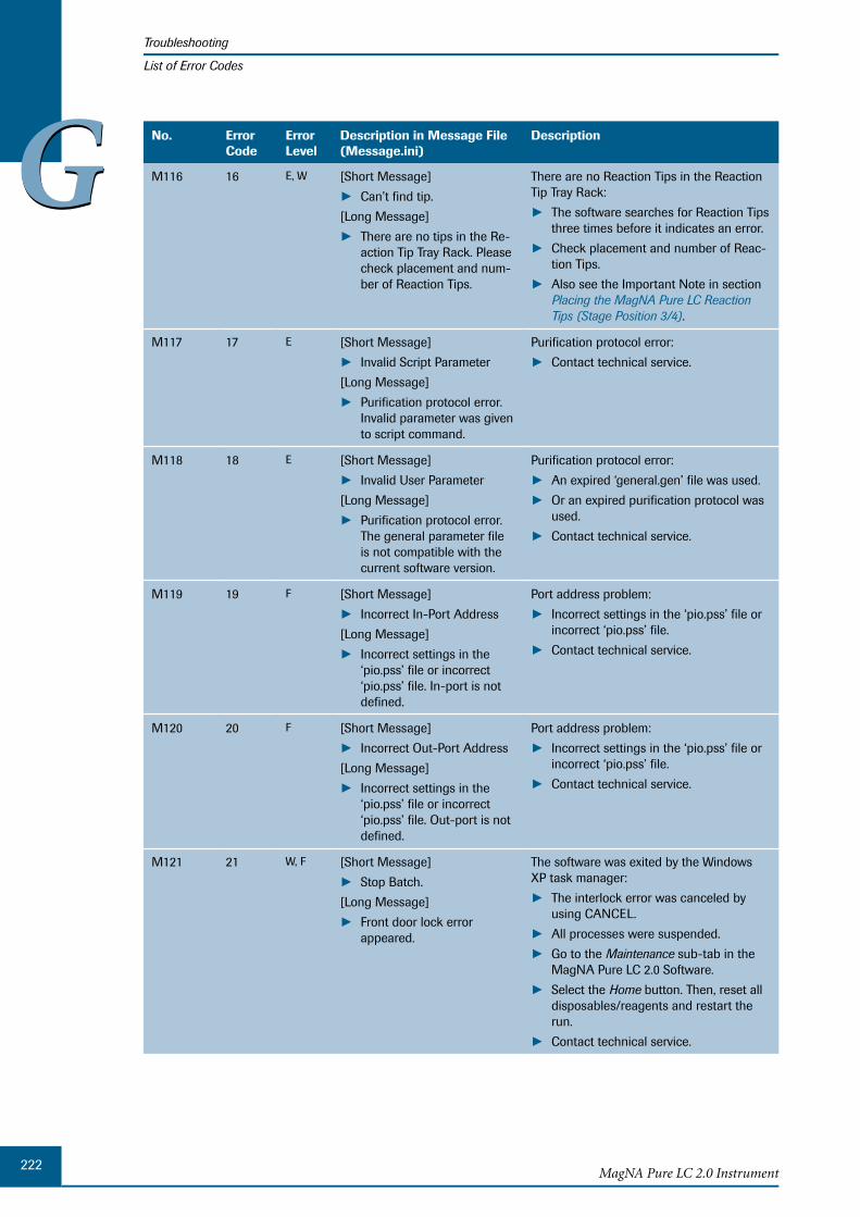
222MagNA Pure LC 2.0 Instrument
Troubleshooting
List of Error Codes
GG No. Error Code
ErrorLevel
Description in Message File (Message.ini)
Description
M116 16 E, W [Short Message]
Can’t find tip. ►[Long Message]
There are no tips in the Re- ►action Tip Tray Rack. Please check placement and num-ber of Reaction Tips.
There are no Reaction Tips in the Reaction Tip Tray Rack:
The software searches for Reaction Tips ►three times before it indicates an error.
Check placement and number of Reac- ►tion Tips.
Also see the Important Note in section ►Placing the MagNA Pure LC Reaction Tips (Stage Position 3/4).
M117 17 E [Short Message]
Invalid Script Parameter ►[Long Message]
Purification protocol error. ►Invalid parameter was given to script command.
Purification protocol error:
Contact technical service. ►
M118 18 E [Short Message]
Invalid User Parameter ►[Long Message]
Purification protocol error. ►The general parameter file is not compatible with the current software version.
Purification protocol error:
An expired ‘general.gen’ file was used. ►Or an expired purification protocol was ►used.
Contact technical service. ►
M119 19 F [Short Message]
Incorrect In-Port Address ►[Long Message]
Incorrect settings in the ►‘pio.pss’ file or incorrect ‘pio.pss’ file. In-port is not defined.
Port address problem:
Incorrect settings in the ‘pio.pss’ file or ►incorrect ‘pio.pss’ file.
Contact technical service. ►
M120 20 F [Short Message]
Incorrect Out-Port Address ►[Long Message]
Incorrect settings in the ►‘pio.pss’ file or incorrect ‘pio.pss’ file. Out-port is not defined.
Port address problem:
Incorrect settings in the ‘pio.pss’ file or ►incorrect ‘pio.pss’ file.
Contact technical service. ►
M121 21 W, F [Short Message]
Stop Batch. ►[Long Message]
Front door lock error ► appeared.
The software was exited by the Windows XP task manager:
The interlock error was canceled by ►using CANCEL.
All processes were suspended. ►Go to the ► Maintenance sub-tab in the MagNA Pure LC 2.0 Software.
Select the ► Home button. Then, reset all disposables/reagents and restart the run.
Contact technical service. ►

223Appendix
Troubleshooting
List of Error Codes
GGNo. Error Code
ErrorLevel
Description in Message File (Message.ini)
Description
M122 22 E [Short Message]
Z movement blocked. ►[Long Message]
Z crash error due to incor- ►rect position of the Liquid Drop Catcher.
Hardware error:
Liquid Drop Catcher was not moved ►back.
Purification protocol error.
Contact technical service to call a ►Roche service engineer.
M123 23 E [Short Message]
Syntax Error in Protocol. ►[Long Message]
Purification protocol error. ►Syntax error in protocol.
Purification protocol error:
Contact technical service. ►
M124 24 E [Short Message]
Parameter Stack Over- ►flowed.
[Long Message]
Purification protocol error or ►internal software error. The data exceeded the capac-ity of the Script command stack.
Purification protocol error or internal soft-ware error:
Contact technical service. ►
M125 25 E [Short Message]
Attempt to execute BIOS ►twice.
[Long Message]
Application Error. Software ►was started twice.
Software was started twice by the user:
MagNA Pure LC 2.0 Software was ►closed because of an error.
The ‘tMAn.exe’ process is still run- ►ning, close it by the Windows XP task manager.
M126 26 E [Short Message]
Invalid Script Parameter ►[Long Message]
Purification protocol error. ►Script parameter is not defined.
Purification protocol error:
A module object that is not defined in ►‘define.pss’ file was assigned.
Contact technical service. ►
M127 27 E [Short Message]
Can’t assign negative ►volume.
[Long Message]
Purification protocol error. ►Invalid pipetting volume.
Purification protocol error:
Contact technical service. ►
M128 31 E [Short Message]
Invalid Volume Table ►[Long Message]
Purification protocol error. ►Incorrect conversion table. Volume (µl)/Pulses conver-sion table is incorrect. The converted value is minus.
Purification protocol error:
Incorrect ‘general.gen’ file. ►Contact technical service. ►
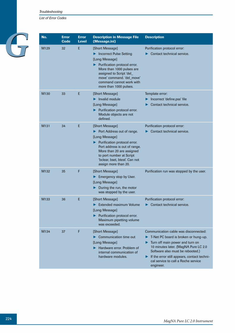
224MagNA Pure LC 2.0 Instrument
Troubleshooting
List of Error Codes
GG No. Error Code
ErrorLevel
Description in Message File (Message.ini)
Description
M129 32 E [Short Message]
Incorrect Pulse Setting ►[Long Message]
Purification protocol error. ►More than 1000 pulses are assigned to Script ‘del_move’ command. ‘del_move’ command cannot work with more than 1000 pulses.
Purification protocol error:
Contact technical service. ►
M130 33 E [Short Message]
Invalid module ►[Long Message]
Purification protocol error. ►Module objects are not defined.
Template error:
Incorrect ‘define.pss’ file ►Contact technical service. ►
M131 34 E [Short Message]
Port Address out of range. ►[Long Message]
Purification protocol error. ►Port address is out of range. More than 20 are assigned to port number at Script ‘bclear, bset, btest’. Can not assign more than 20.
Purification protocol error:
Contact technical service. ►
M132 35 F [Short Message]
Emergency stop by User. ►[Long Message]
During the run, the motor ►was stopped by the user.
Purification run was stopped by the user.
M133 36 E [Short Message]
Extended maximum Volume ►[Long Message]
Purification protocol error. ►Maximum pipetting volume was exceeded.
Purification protocol error:
Contact technical service. ►
M134 37 F [Short Message]
Communication time out ►[Long Message]
Hardware error. Problem of ►internal communication of hardware modules.
Communication cable was disconnected:
T-Net PC board is broken or hung-up. ►Turn off main power and turn on ►10 minutes later. (MagNA Pure LC 2.0 Software also must be rebooted.)
If the error still appears, contact techni- ►cal service to call a Roche service engineer.

225Appendix
Troubleshooting
List of Error Codes
GGNo. Error Code
ErrorLevel
Description in Message File (Message.ini)
Description
M135 38 F [Short Message]
Motor Power Fail ►[Long Message]
The motor was immediately ►stopped by the input of an alarm signal to the motor controller.
Hardware problem:
The motor was stopped abruptly by the ►input of an alarm signal to the motor controller.
The main power must be turned off or ►the power supply to the motors must be shut down by opening the door and restarting the Instrument.
If the error still appears, contact techni- ►cal service to call a Roche service engineer.
M136 39 F [Short Message]
Dropcatcher Movement ►Failure
[Long Message]
Hardware error. Dropcatch- ►er unit failed to move to ON position.
Hardware problem:
The Liquid Drop Catcher did not move ►to the clot sensor ‘on’ position.
Contact technical service to have a ►Roche service engineer check the assembly of magnetic plate and make it move smoothly.
M137 40 F [Short Message]
Tip Off Error ►[Long Message]
Hardware error. Tip can not ►be discarded.
Hardware problem:
When ‘Tip_OFF’ command is to be ►executed, the Tip Eject plate did not move to the position of check sensor for Tip Eject.
Contact technical service to call a ►Roche service engineer.
M138 42 E [Short Message]
Stack Overflow. ►[Long Message]
Purification protocol error. ►When Script ‘Stack’ com-mand was executed to use more than 2 data sets, there was 1 or no data existing in the ‘Stack’.
Purification protocol error:
Contact technical service. ►
M139 43 E [Short Message]
Calculation Error ►[Long Message]
Purification protocol error. ►In Script ‘stack’ Command (Div, Mod), 0 was sub-tracted.
Purification protocol error:
Contact technical service. ►
M140 44 - [Short Message]
Undefined General Label. ►[Long Message]
Purification protocol error: ►an expired ‘general.gen’ file or an expired purification protocol was used.
Purification protocol error:
An expired ‘general.gen’ file or an ex- ►pired purification protocol was used.
Contact technical service. ►

226MagNA Pure LC 2.0 Instrument
Troubleshooting
List of Error Codes
GG No. Error Code
ErrorLevel
Description in Message File (Message.ini)
Description
M141 45 E [Short Message]
Invalid Stack Command ►[Long Message]
Purification protocol error. ►‘Stack’ command is not defined.
Purification protocol error:
Contact technical service. ►
M142 46 E [Short Message]
Invalid Motor Name ►[Long Message]
Purification protocol error. ►Motor name is not defined.
Purification protocol error:
Invalid files were used. ►Contact technical service. ►
M143 47 F [Short Message]
Invalid Tool Number ►[Long Message]
Purification protocol error. ►Tool command is not defined.
Purification protocol error:
Invalid ‘general.gen’ file was used. ►Contact technical service. ►
M144 48 E [Short Message]
Purification protocol error ►[Long Message]
Invalid Volume Table. ►
Purification protocol error:
Invalid ‘general.gen’ file was used. ►Contact technical service. ►
M145 49 W [Short Message]
Hardware error ►[Long Message]
Heat Block temperature ►was out of range.
Hardware problem:
Peltier element of the Heating Unit may ►be broken.
Contact technical service to call a ►Roche service engineer.
M146 50 W [Short Message]
Hardware error ►[Long Message]
Cool Block1 temperature ►was out of range.
Hardware problem:
Peltier element of the Cooling Unit 1 ►may be broken.
Contact technical service to call a ►Roche service engineer.
M147 51 W [Short Message]
Hardware error ►[Long Message]
Cool Block2 temperature ►was out of range.
Hardware problem:
Peltier element of the Cooling Unit 2 ►may be broken.
Contact technical service to call a ►Roche service engineer.
M148 52 F [Short Message]
Air filter fan stopped. ►[Long Message]
During the run, the fan ►stopped for more than 10 minutes.
During the run, the fan stopped for more than 10 minutes.
Contact technical service to have a ►Roche service engineer check whether the fan is broken.
M149 53 F [Short Message]
Tip Off Error ►[Long Message]
Reaction tip loss: check ► O-Rings at Nozzle Head.
Reaction Tip loss:
Check placement of Reaction Tips at ►Nozzle Head.
Check O-Rings at Nozzle Head. ►Check samples for clotting. ►

227Appendix
Troubleshooting
List of Error Codes
GGNo. Error Code
ErrorLevel
Description in Message File (Message.ini)
Description
M150 54 F [Short Message]
Clot error ►[Long Message]
During the run, clot error ►has happened.
Clot error:
Check light conditions. ►Incorrect Lysis Buffer used. ►
M151 56 F [Short Message]
Collision During Surface ►Scan.
[Long Message]
Remove any obstacles from ►the Reagent/Sample Stage.
This error appears only during execu- ►tion of the surface scan due to an ob-stacle present on the Reagent/Sample Stage.
Remove any obstacles from the ► Reagent/Sample Stage.
Ensure that accessories and disposable ►plastics are placed correctly.
M152 57 E [Short Message]
Skip Reagent Dispensing. ►[Long Message]
During dispensing of the ►reagents, Z crash appears.
During vertical movement of the Nozzle ►Head the Reaction Tips hit an obstacle.
Check that there are no obstacles like a ►Tub Lid Seal present on a Reagent Tub.
M196 58 F [Short Message]
Temperature Error ►HeatBlock Bank
[Long Message]
Additional Temperature ►sensor is not in range. (Heater Unit)
Hardware problem:
Temperature Controller (Heater Unit) or ►sensor may be broken.
Contact technical service to call a ►Roche service engineer.
M197 59 F [Short Message]
Temperature Error ►CoolBlock 1
[Long Message]
Additional Temperature ►sensor is not in range. (Cooling Block 1)
Hardware problem:
Temperature Controller (Cooling ►Block 1) or sensor may be broken.
Contact technical service to call a ►Roche service engineer.
M198 60 F [Short Message]
Temperature Error ►CoolBlock 2
[Long Message]
Additional Temperature ►sensor is not in range. (Cooling Block 2)
Hardware problem:
Temperature Controller (Cooling ►Block 2) or sensor may be broken.
Contact technical service to call a ►Roche service engineer.
M199 61 F [Short Message]
PSA Monitor Error ►[Long Message]
When the value of PSA ►Monitor before getting tips is 100 or less.
Hardware problem:
PSA Monitor may be broken. ►Contact technical service to call a ►Roche service engineer.

228MagNA Pure LC 2.0 Instrument
Troubleshooting
List of Error Codes
GGHost Communication Error List Messages
No. Error Code
ErrorLevel
Description in Message File (Message.ini)
Description
M200 70 E [Short Message]
Segment sequence error ►[Long Message]
Error: The message seg- ►ments were not in the proper order, or required segments are missing.
Communication Message problem:
The message segments were not in the ►proper order.
Required segments are missing. ►
M201 71 E [Short Message]
Required field missing. ►[Long Message]
Error: A required field is ►missing from a segment.
Communication Message problem:
A required field is missing from a ► segment.
M202 72 E [Short Message]
Data type error ►[Long Message]
Error: The field contained ►data of the wrong data type.
Communication Message problem:
A field contained data of the wrong data ►type, e.g., an NM field contained “FOO”.
M203 73 E [Short Message]
Table value not found. ►[Long Message]
Error: A field of data type ID ►or IS was compared against the corresponding table, and no match was found.
Communication Message problem:
A field of data type ID or IS was com- ►pared against the corresponding table, but no match was found.
M204 74 E [Short Message]
Reply time-out ►[Long Message]
Error of time-out ►
Check if connection with Host is correct. ►
M205 75 E [Short Message]
Not in ready ►[Long Message]
When the content of ► Acknowledgment Code is an error (e.g., “AE”).
This error is caused by the Host. ►
M206 76 E [Short Message]
File could not be deleted. ►Check if access rights of a shared folder ►are correct.
M207 77 E [Short Message]
Sharing directory could not ►be found.
[Long Message]
Sharing directory could not ►be found (When you do the order by using file-sharing capabilities).
Check if a shared folder exists. ►Check if connection with Host is correct. ►
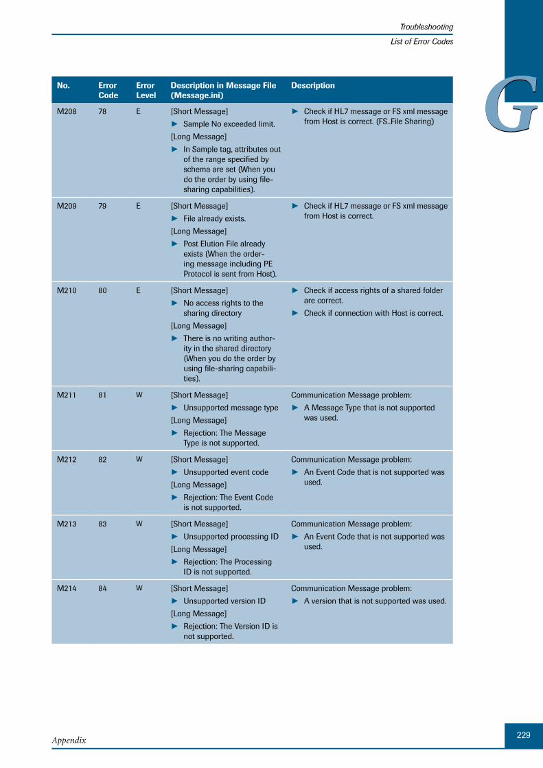
229Appendix
Troubleshooting
List of Error Codes
GGNo. Error Code
ErrorLevel
Description in Message File (Message.ini)
Description
M208 78 E [Short Message]
Sample No exceeded limit. ►[Long Message]
In Sample tag, attributes out ►of the range specified by schema are set (When you do the order by using file-sharing capabilities).
Check if HL7 message or FS xml message ►from Host is correct. (FS..File Sharing)
M209 79 E [Short Message]
File already exists. ►[Long Message]
Post Elution File already ►exists (When the order-ing message including PE Protocol is sent from Host).
Check if HL7 message or FS xml message ►from Host is correct.
M210 80 E [Short Message]
No access rights to the ►sharing directory
[Long Message]
There is no writing author- ►ity in the shared directory (When you do the order by using file-sharing capabili-ties).
Check if access rights of a shared folder ►are correct.
Check if connection with Host is correct. ►
M211 81 W [Short Message]
Unsupported message type ►[Long Message]
Rejection: The Message ►Type is not supported.
Communication Message problem:
A Message Type that is not supported ►was used.
M212 82 W [Short Message]
Unsupported event code ►[Long Message]
Rejection: The Event Code ►is not supported.
Communication Message problem:
An Event Code that is not supported was ►used.
M213 83 W [Short Message]
Unsupported processing ID ►[Long Message]
Rejection: The Processing ►ID is not supported.
Communication Message problem:
An Event Code that is not supported was ►used.
M214 84 W [Short Message]
Unsupported version ID ►[Long Message]
Rejection: The Version ID is ►not supported.
Communication Message problem:
A version that is not supported was used. ►
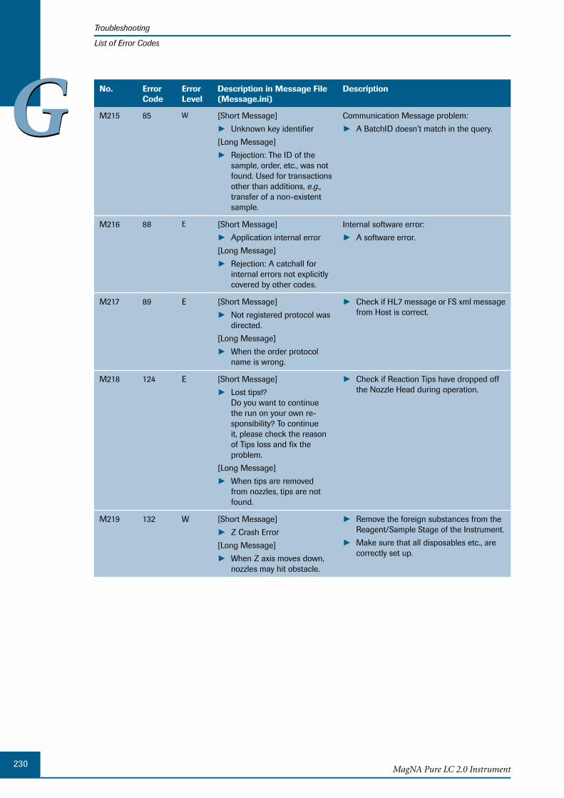
230MagNA Pure LC 2.0 Instrument
Troubleshooting
List of Error Codes
GG No. Error Code
ErrorLevel
Description in Message File (Message.ini)
Description
M215 85 W [Short Message]
Unknown key identifier ►[Long Message]
Rejection: The ID of the ►sample, order, etc., was not found. Used for transactions other than additions, e.g., transfer of a non-existent sample.
Communication Message problem:
A BatchID doesn’t match in the query. ►
M216 88 E [Short Message]
Application internal error ►[Long Message]
Rejection: A catchall for ►internal errors not explicitly covered by other codes.
Internal software error:
A software error. ►
M217 89 E [Short Message]
Not registered protocol was ►directed.
[Long Message]
When the order protocol ►name is wrong.
Check if HL7 message or FS xml message ►from Host is correct.
M218 124 E [Short Message]
Lost tips!? ►Do you want to continue the run on your own re-sponsibility? To continue it, please check the reason of Tips loss and fix the problem.
[Long Message]
When tips are removed ►from nozzles, tips are not found.
Check if Reaction Tips have dropped off ►the Nozzle Head during operation.
M219 132 W [Short Message]
Z Crash Error ►[Long Message]
When Z axis moves down, ►nozzles may hit obstacle.
Remove the foreign substances from the ►Reagent/Sample Stage of the Instrument.
Make sure that all disposables etc., are ►correctly set up.
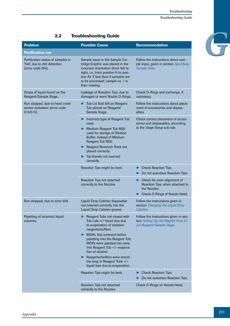
231Appendix
Troubleshooting
Troubleshooting Guide
GG2.2 Troubleshooting Guide
Problem Possible Cause Recommendation
Purification run
Purification status of samples is ‘Fail’, due to clot detection (error code 054).
Sample input in the Sample Car-tridge Graphic was placed in the incorrect orientation (from left to right, i.e., from position H to posi-tion A): if less than 8 samples are to be processed, sample no. 1 is then missing.
Follow the instructions about sam-ple input, given in section Specifying Sample Data.
Drops of liquid found on the Reagent/Sample Stage.
Leakage of Reaction Tips, due to damaged or worn Nozzle O-Rings.
Check O-Rings and exchange, if necessary.
Run stopped, due to head crash sensor activation (error code 010/013).
Tub Lid Seal left on Reagent ►Tub placed on Reagent/ Sample Stage.
Follow the instructions about place-ment of accessories and dispos-ables.
Incorrect type of Reagent Tub ►used.
Medium Reagent Tub M20 ►used for storage of Dilution Buffer, instead of Medium Reagent Tub M30.
Reagent Reservoir Rack not ►placed correctly.
Tip Stands not inserted ► correctly.
Check correct placement of acces-sories and disposables, according to the Stage Setup sub-tab.
Reaction Tips might be bent. Check Reaction Tips. ►Do not autoclave Reaction Tips. ►
Reaction Tips not attached correctly to the Nozzles.
Check for even alignment of ►Reaction Tips, when attached to the Nozzles.
Check O-Rings of Nozzle Head. ►
Run stopped, due to error 039. Liquid Drop Catcher disposable not inserted correctly into the Liquid Drop Catcher groove.
Follow the instructions given in section Changing the Liquid Drop Catcher.
Pipetting of incorrect liquid volumes.
Reagent Tubs not closed with ►Tub Lids => liquid loss due to evaporation of isolation reagents/buffers.
MGPs: Not vortexed before ►pipetting into the Reagent Tub; MGPs were pipetted too early into Reagent Tub => evapora-tion of alcohol.
Reagents/buffers were stored ►too long in Reagent Tubs => liquid loss due to evaporation.
Follow the instructions given in sec-tion Setting Up the MagNA Pure LC 2.0 Reagent/Sample Stage.
Reaction Tips might be bent. Check Reaction Tips. ►Do not autoclave Reaction Tips. ►
Reaction Tips not attached correctly to the Nozzles.
Check O-Rings on Nozzle Head.
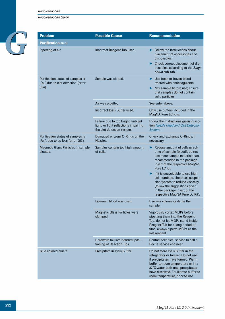
232MagNA Pure LC 2.0 Instrument
Troubleshooting
Troubleshooting Guide
GG Problem Possible Cause Recommendation
Purification run
Pipetting of air Incorrect Reagent Tub used. Follow the instructions about ►placement of accessories and disposables.
Check correct placement of dis- ►posables, according to the Stage Setup sub-tab.
Purification status of samples is ‘Fail’, due to clot detection (error 054).
Sample was clotted. Use fresh or frozen blood ►treated with anticoagulants.
Mix sample before use; ensure ►that samples do not contain solid particles.
Air was pipetted. See entry above.
Incorrect Lysis Buffer used. Only use buffers included in the MagNA Pure LC Kits.
Failure due to too bright ambient light, or light reflections impairing the clot detection system.
Follow the instructions given in sec-tion Nozzle Head and Clot Detection System.
Purification status of samples is 'Fail', due to tip loss (error 053).
Damaged or worn O-Rings on the Nozzles.
Check and exchange O-Rings, if necessary.
Magnetic Glass Particles in sample eluates.
Samples contain too high amount of cells.
Reduce amount of cells or vol- ►ume of sample (blood); do not use more sample material than recommended in the package insert of the respective MagNA Pure LC Kit.
If it is unavoidable to use high ►cell numbers, shear cell suspen-sion/lysates to reduce viscosity (follow the suggestions given in the package insert of the respective MagNA Pure LC Kit).
Lipaemic blood was used. Use less volume or dilute the sample.
Magnetic Glass Particles were clumped.
Vigorously vortex MGPs before pipetting them into the Reagent Tub; do not let MGPs stand inside Reagent Tub for a long period of time, always pipette MGPs as the last reagent.
Hardware failure: Incorrect posi-tioning of Reaction Tips.
Contact technical service to call a Roche service engineer.
Blue colored eluate Precipitate in Lysis Buffer. Do not store Lysis Buffer in the refrigerator or freezer. Do not use if precipitates have formed. Warm buffer to room temperature or in a 37°C water bath until precipitates have dissolved. Equilibrate buffer to room temperature, prior to use.
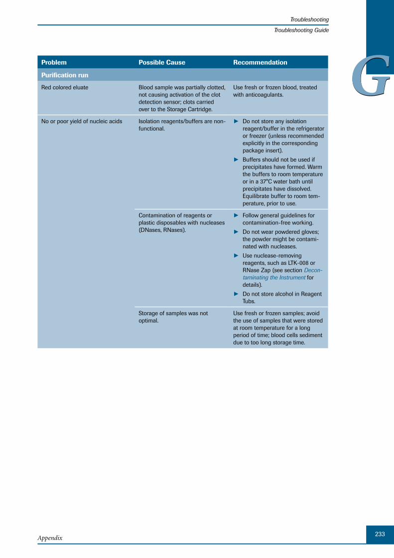
233Appendix
Troubleshooting
Troubleshooting Guide
GGProblem Possible Cause Recommendation
Purification run
Red colored eluate Blood sample was partially clotted, not causing activation of the clot detection sensor; clots carried over to the Storage Cartridge.
Use fresh or frozen blood, treated with anticoagulants.
No or poor yield of nucleic acids Isolation reagents/buffers are non-functional.
Do not store any isolation ►reagent/buffer in the refrigerator or freezer (unless recommended explicitly in the corresponding package insert).
Buffers should not be used if ►precipitates have formed. Warm the buffers to room temperature or in a 37°C water bath until precipitates have dissolved. Equilibrate buffer to room tem-perature, prior to use.
Contamination of reagents or plastic disposables with nucleases (DNases, RNases).
Follow general guidelines for ►contamination-free working.
Do not wear powdered gloves; ►the powder might be contami-nated with nucleases.
Use nuclease-removing ►reagents, such as LTK-008 or RNase Zap (see section Decon-taminating the Instrument for details).
Do not store alcohol in Reagent ►Tubs.
Storage of samples was not optimal.
Use fresh or frozen samples; avoid the use of samples that were stored at room temperature for a long period of time; blood cells sediment due to too long storage time.
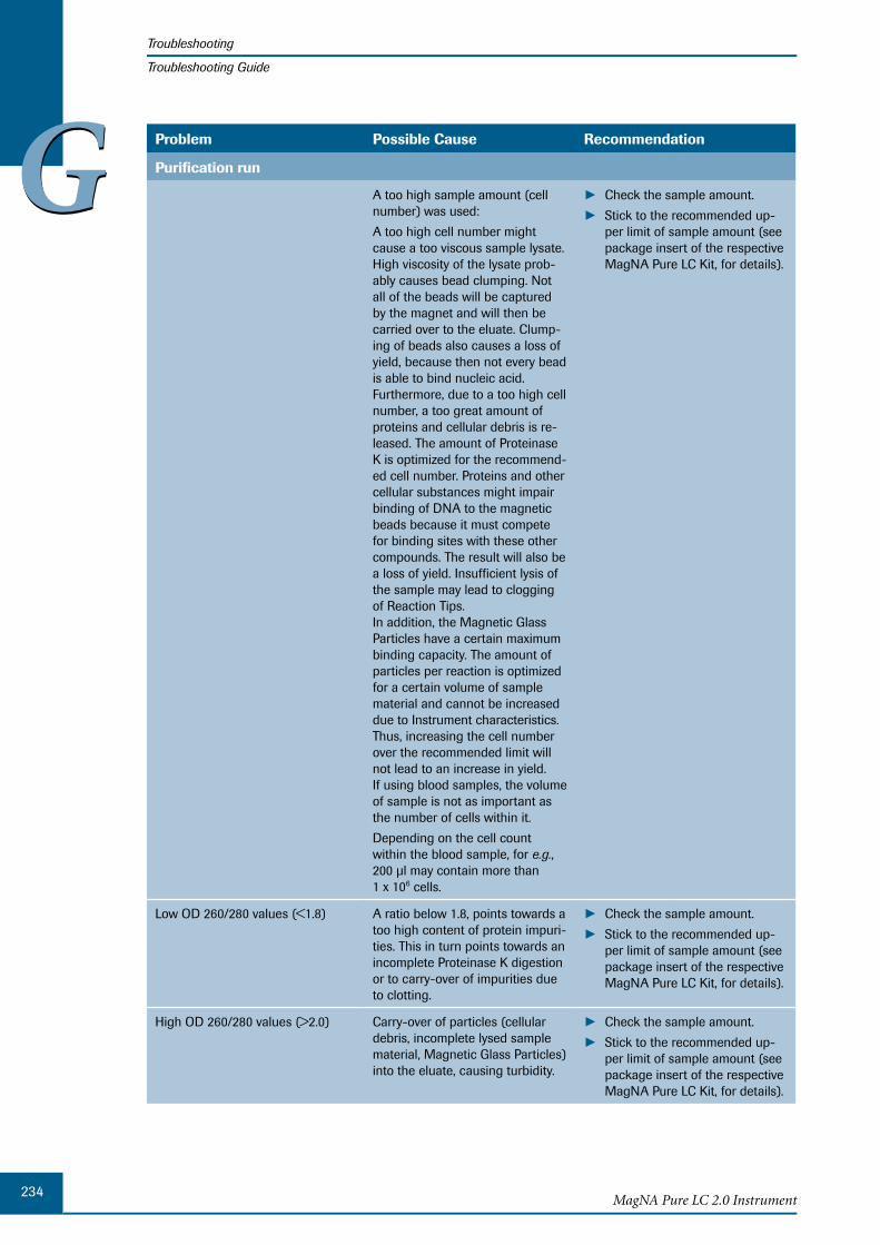
234MagNA Pure LC 2.0 Instrument
Troubleshooting
Troubleshooting Guide
GG Problem Possible Cause Recommendation
Purification run
A too high sample amount (cell number) was used:
A too high cell number might cause a too viscous sample lysate. High viscosity of the lysate prob-ably causes bead clumping. Not all of the beads will be captured by the magnet and will then be carried over to the eluate. Clump-ing of beads also causes a loss of yield, because then not every bead is able to bind nucleic acid. Furthermore, due to a too high cell number, a too great amount of proteins and cellular debris is re-leased. The amount of Proteinase K is optimized for the recommend-ed cell number. Proteins and other cellular substances might impair binding of DNA to the magnetic beads because it must compete for binding sites with these other compounds. The result will also be a loss of yield. Insufficient lysis of the sample may lead to clogging of Reaction Tips. In addition, the Magnetic Glass Particles have a certain maximum binding capacity. The amount of particles per reaction is optimized for a certain volume of sample material and cannot be increased due to Instrument characteristics. Thus, increasing the cell number over the recommended limit will not lead to an increase in yield. If using blood samples, the volume of sample is not as important as the number of cells within it.
Depending on the cell count within the blood sample, for e.g., 200 µl may contain more than 1 x 10⁶ cells.
Check the sample amount. ►Stick to the recommended up- ►per limit of sample amount (see package insert of the respective MagNA Pure LC Kit, for details).
Low OD 260/280 values (<1.8) A ratio below 1.8, points towards a too high content of protein impuri-ties. This in turn points towards an incomplete Proteinase K digestion or to carry-over of impurities due to clotting.
Check the sample amount. ►Stick to the recommended up- ►per limit of sample amount (see package insert of the respective MagNA Pure LC Kit, for details).
High OD 260/280 values (>2.0) Carry-over of particles (cellular debris, incomplete lysed sample material, Magnetic Glass Particles) into the eluate, causing turbidity.
Check the sample amount. ►Stick to the recommended up- ►per limit of sample amount (see package insert of the respective MagNA Pure LC Kit, for details).
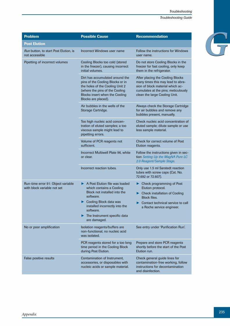
235Appendix
Troubleshooting
Troubleshooting Guide
GGProblem Possible Cause Recommendation
Post Elution
Run button, to start Post Elution, is not accessible
Incorrect Windows user name Follow the instructions for Windows user name.
Pipetting of incorrect volumes Cooling Blocks too cold (stored in the freezer), causing incorrect initial volumes.
Do not store Cooling Blocks in the freezer for fast cooling, only keep them in the refrigerator.
Dirt has accumulated around the pins of the Cooling Blocks or in the holes of the Cooling Unit 2 (where the pins of the Cooling Blocks insert when the Cooling Blocks are placed).
After placing the Cooling Blocks many times this may lead to abra-sion of block material which ac-cumulates at the pins; meticulously clean the large Cooling Unit.
Air bubbles in the wells of the Storage Cartridge.
Always check the Storage Cartridge for air bubbles and remove any bubbles present, manually.
Too high nucleic acid concen-tration of eluted samples; a too viscous sample might lead to pipetting errors.
Check nucleic acid concentration of eluted sample; dilute sample or use less sample material.
Volume of PCR reagents not sufficient.
Check for correct volume of Post Elution reagents.
Incorrect Multiwell Plate 96, white or clear.
Follow the instructions given in sec-tion Setting Up the MagNA Pure LC 2.0 Reagent/Sample Stage.
Incorrect reaction tubes. Only use 1.5 ml Sarstedt reaction tubes with screw caps (Cat. No. 72.692 or 72.607).
Run-time error 91: Object variable with block variable not set
A Post Elution file was loaded ►which contains a Cooling Block not installed into the software.
Cooling Block data was ►installed incorrectly into the software.
The Instrument specific data ►are damaged.
Check programming of Post ► Elution protocol.
Check installation of Cooling ►Block files.
Contact technical service to call ►a Roche service engineer.
No or poor amplification Isolation reagents/buffers are non-functional, no nucleic acid was isolated.
See entry under ‘Purification Run’.
PCR reagents stored for a too long time period in the Cooling Block during Post Elution.
Prepare and store PCR reagents shortly before the start of the Post Elution run.
False positive results Contamination of Instrument, accessories, or disposables with nucleic acids or sample material.
Check general guide lines for contamination-free working, follow instructions for decontamination and disinfection.

236MagNA Pure LC 2.0 Instrument
Troubleshooting
Troubleshooting Guide
GG Problem Possible Cause Recommendation
Post Elution
Cross contamination Air bubbles at the bottom of Sample Cartridge wells.
During aspirating, a volume from the Sample Cartridge wells which contains air bubbles, might burst causing formation of aerosols.
Splashing due to clotting during the process.
Avoid clotting by using only the specified amount of sample mate-rial.
Liquid Drop Catcher dispos- ►able not changed
Tip Discard was deactivated ►during Post Elution when dispensing samples.
Follow instructions given in section Changing the Liquid Drop Catcher.
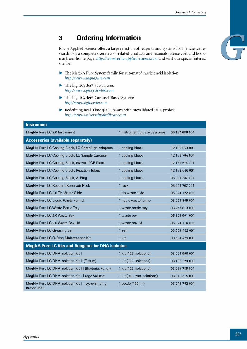
237Appendix
Ordering Information
GG3 Ordering InformationRoche Applied Science offers a large selection of reagents and systems for life science re-search. For a complete overview of related products and manuals, please visit and book-mark our home page, http://www.roche-applied-science.com and visit our special interest site for:
T ► he MagNA Pure System family for automated nucleic acid isolation: http://www.magnapure.com
T ► he LightCycler® 480 System: http://www.lightcycler480.com
T ► he LightCycler® Carousel-Based System: http://www.lightcycler.com
Redefining Real-Time qPCR Assays with prevalidated UPL-probes: ► http://www.universalprobelibrary.com
Instrument
MagNA Pure LC 2.0 Instrument 1 instrument plus accessories 05 197 686 001
Accessories (available separately)
MagNA Pure LC Cooling Block, LC Centrifuge Adapters 1 cooling block 12 190 664 001
MagNA Pure LC Cooling Block, LC Sample Carousel 1 cooling block 12 189 704 001
MagNA Pure LC Cooling Block, 96-well PCR Plate 1 cooling block 12 189 674 001
MagNA Pure LC Cooling Block, Reaction Tubes 1 cooling block 12 189 666 001
MagNA Pure LC Cooling Block, A-Ring 1 cooling block 03 201 287 001
MagNA Pure LC Reagent Reservoir Rack 1 rack 03 253 767 001
MagNA Pure LC 2.0 Tip Waste Slide 1 tip waste slide 05 324 122 001
MagNA Pure LC Liquid Waste Funnel 1 liquid waste funnel 03 253 805 001
MagNA Pure LC Waste Bottle Tray 1 waste bottle tray 03 253 813 001
MagNA Pure LC 2.0 Waste Box 1 waste box 05 323 991 001
MagNA Pure LC 2.0 Waste Box Lid 1 waste box lid 05 324 114 001
MagNA Pure LC Greasing Set 1 set 03 561 402 001
MagNA Pure LC O-Ring Maintenance Kit 1 kit 03 561 429 001
MagNA Pure LC Kits and Reagents for DNA Isolation
MagNA Pure LC DNA Isolation Kit I 1 kit (192 isolations) 03 003 990 001
MagNA Pure LC DNA Isolation Kit II (Tissue) 1 kit (192 isolations) 03 186 229 001
MagNA Pure LC DNA Isolation Kit III (Bacteria, Fungi) 1 kit (192 isolations) 03 264 785 001
MagNA Pure LC DNA Isolation Kit - Large Volume 1 kit (96 - 288 isolations) 03 310 515 001
MagNA Pure LC DNA Isolation Kit I – Lysis/Binding Buffer Refill
1 bottle (100 ml) 03 246 752 001
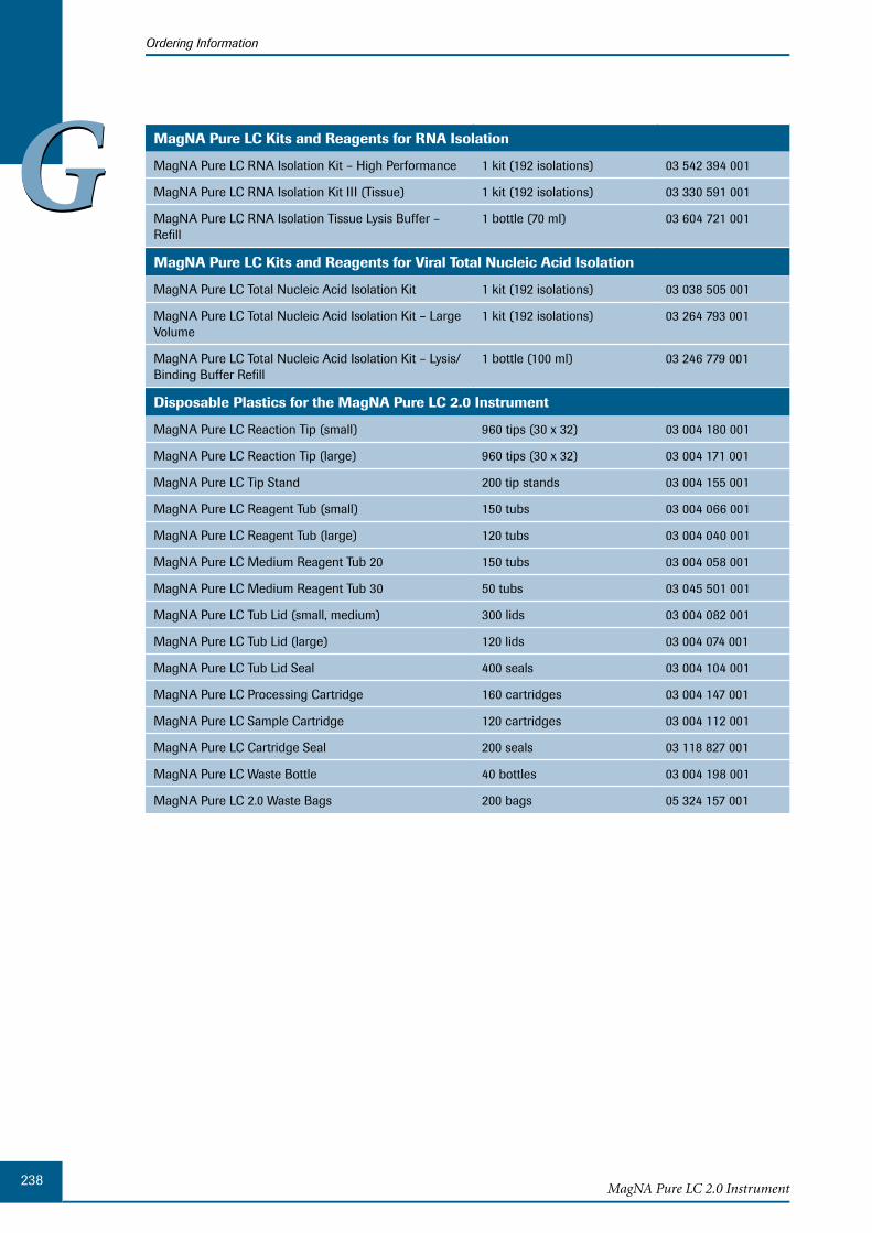
238MagNA Pure LC 2.0 Instrument
Ordering Information
GG MagNA Pure LC Kits and Reagents for RNA Isolation
MagNA Pure LC RNA Isolation Kit – High Performance 1 kit (192 isolations) 03 542 394 001
MagNA Pure LC RNA Isolation Kit III (Tissue) 1 kit (192 isolations) 03 330 591 001
MagNA Pure LC RNA Isolation Tissue Lysis Buffer – Refill
1 bottle (70 ml) 03 604 721 001
MagNA Pure LC Kits and Reagents for Viral Total Nucleic Acid Isolation
MagNA Pure LC Total Nucleic Acid Isolation Kit 1 kit (192 isolations) 03 038 505 001
MagNA Pure LC Total Nucleic Acid Isolation Kit – Large Volume
1 kit (192 isolations) 03 264 793 001
MagNA Pure LC Total Nucleic Acid Isolation Kit – Lysis/Binding Buffer Refill
1 bottle (100 ml) 03 246 779 001
Disposable Plastics for the MagNA Pure LC 2.0 Instrument
MagNA Pure LC Reaction Tip (small) 960 tips (30 x 32) 03 004 180 001
MagNA Pure LC Reaction Tip (large) 960 tips (30 x 32) 03 004 171 001
MagNA Pure LC Tip Stand 200 tip stands 03 004 155 001
MagNA Pure LC Reagent Tub (small) 150 tubs 03 004 066 001
MagNA Pure LC Reagent Tub (large) 120 tubs 03 004 040 001
MagNA Pure LC Medium Reagent Tub 20 150 tubs 03 004 058 001
MagNA Pure LC Medium Reagent Tub 30 50 tubs 03 045 501 001
MagNA Pure LC Tub Lid (small, medium) 300 lids 03 004 082 001
MagNA Pure LC Tub Lid (large) 120 lids 03 004 074 001
MagNA Pure LC Tub Lid Seal 400 seals 03 004 104 001
MagNA Pure LC Processing Cartridge 160 cartridges 03 004 147 001
MagNA Pure LC Sample Cartridge 120 cartridges 03 004 112 001
MagNA Pure LC Cartridge Seal 200 seals 03 118 827 001
MagNA Pure LC Waste Bottle 40 bottles 03 004 198 001
MagNA Pure LC 2.0 Waste Bags 200 bags 05 324 157 001
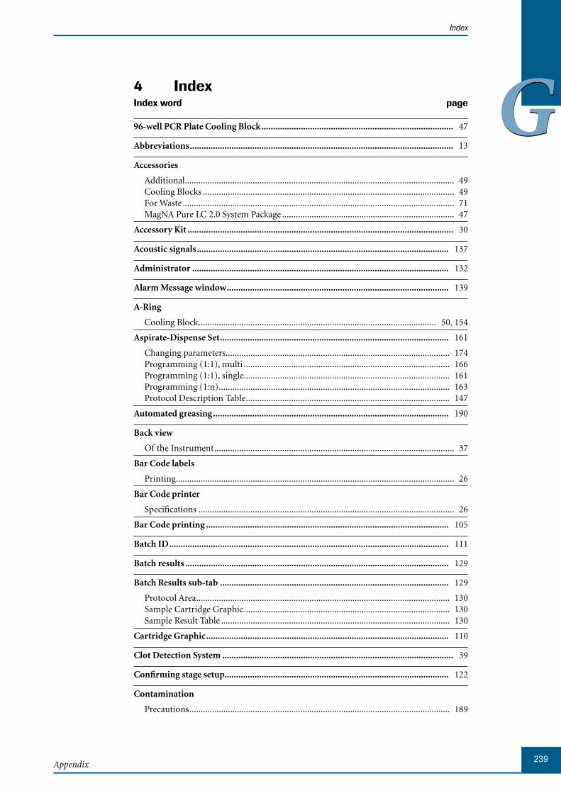
239Appendix
Index
GGIndex4 Index word page
96-well PCR Plate Cooling Block ................................................................................... 47
Abbreviations .................................................................................................................. 13
Accessories
Additional ....................................................................................................................... 49Cooling Blocks ............................................................................................................... 49For Waste ........................................................................................................................ 71MagNA Pure LC 2.0 System Package ............................................................................ 47
Accessory Kit ................................................................................................................... 30
Acoustic signals ............................................................................................................. 137
Administrator ............................................................................................................... 132
Alarm Message window ................................................................................................ 139
A-Ring
Cooling Block ......................................................................................................... 50, 154
Aspirate-Dispense Set ................................................................................................... 161
Changing parameters ................................................................................................... 174Programming (1:1), multi ........................................................................................... 166Programming (1:1), single........................................................................................... 161Programming (1:n) ...................................................................................................... 163Protocol Description Table .......................................................................................... 147
Automated greasing ...................................................................................................... 190
Back view
Of the Instrument .......................................................................................................... 37
Bar Code labels
Printing ........................................................................................................................... 26
Bar Code printer
Specifications ................................................................................................................. 26
Bar Code printing ......................................................................................................... 105
Batch ID ......................................................................................................................... 111
Batch results .................................................................................................................. 129
Batch Results sub-tab ................................................................................................... 129
Protocol Area ................................................................................................................ 130Sample Cartridge Graphic ........................................................................................... 130Sample Result Table ..................................................................................................... 130
Cartridge Graphic ......................................................................................................... 110
Clot Detection System .................................................................................................... 39
Confirming stage setup................................................................................................. 122
Contamination
Precautions ................................................................................................................... 189
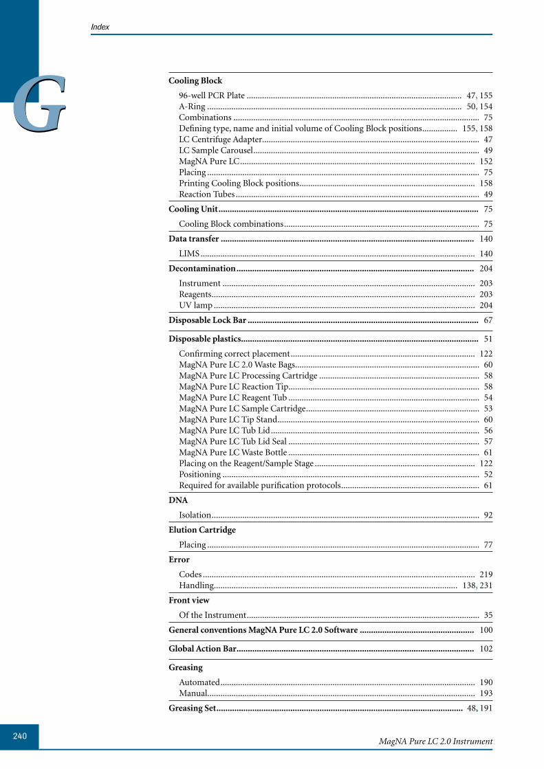
240MagNA Pure LC 2.0 Instrument
Index
GGCooling Block
96-well PCR Plate .................................................................................................. 47, 155A-Ring .................................................................................................................... 50, 154Combinations ................................................................................................................ 75Defining type, name and initial volume of Cooling Block positions ................ 155, 158LC Centrifuge Adapter................................................................................................... 47LC Sample Carousel ....................................................................................................... 49MagNA Pure LC ........................................................................................................... 152Placing ............................................................................................................................ 75Printing Cooling Block positions ................................................................................ 158Reaction Tubes ............................................................................................................... 49
Cooling Unit .................................................................................................................... 75
Cooling Block combinations ......................................................................................... 75
Data transfer ................................................................................................................. 140
LIMS ............................................................................................................................. 140
Decontamination .......................................................................................................... 204
Instrument ................................................................................................................... 203Reagents ........................................................................................................................ 203UV lamp ....................................................................................................................... 204
Disposable Lock Bar ....................................................................................................... 67
Disposable plastics .......................................................................................................... 51
Confirming correct placement .................................................................................... 122MagNA Pure LC 2.0 Waste Bags .................................................................................... 60MagNA Pure LC Processing Cartridge ......................................................................... 58MagNA Pure LC Reaction Tip ....................................................................................... 58MagNA Pure LC Reagent Tub ....................................................................................... 54MagNA Pure LC Sample Cartridge ............................................................................... 53MagNA Pure LC Tip Stand ............................................................................................ 60MagNA Pure LC Tub Lid ............................................................................................... 56MagNA Pure LC Tub Lid Seal ....................................................................................... 57MagNA Pure LC Waste Bottle ....................................................................................... 61Placing on the Reagent/Sample Stage ......................................................................... 122Positioning ..................................................................................................................... 52Required for available purification protocols ............................................................... 61
DNA
Isolation .......................................................................................................................... 92
Elution Cartridge
Placing ............................................................................................................................ 77
Error
Codes ............................................................................................................................ 219Handling ............................................................................................................... 138, 231
Front view
Of the Instrument .......................................................................................................... 35
General conventions MagNA Pure LC 2.0 Software ................................................... 100
Global Action Bar .......................................................................................................... 102
Greasing
Automated .................................................................................................................... 190Manual .......................................................................................................................... 193
Greasing Set .............................................................................................................. 48, 191
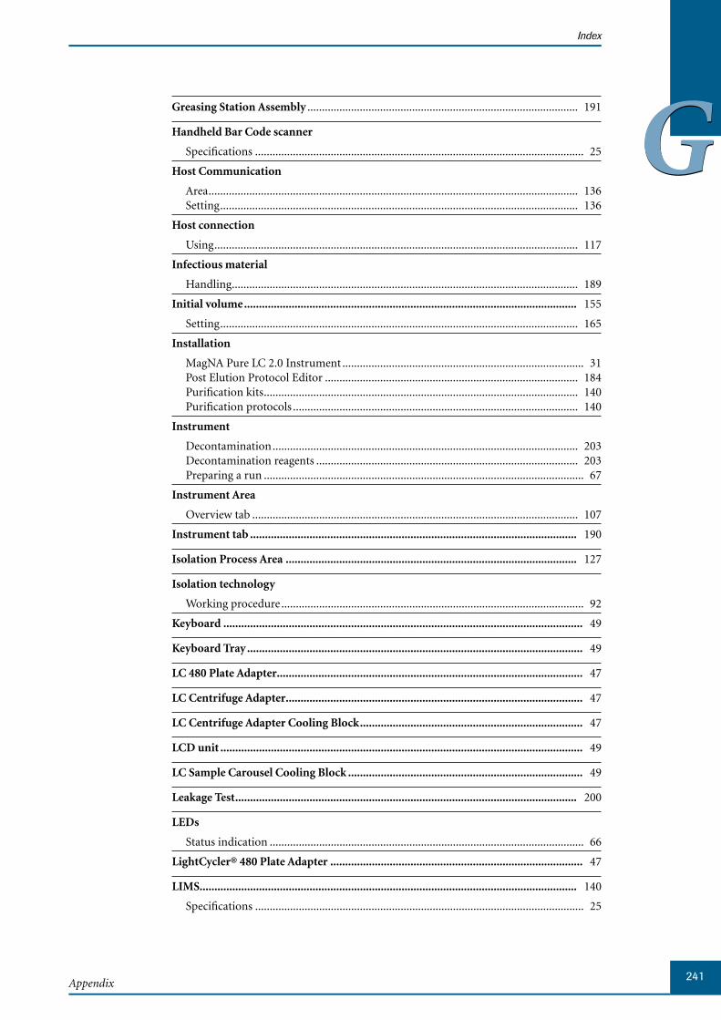
241Appendix
Index
GGGreasing Station Assembly ............................................................................................. 191
Handheld Bar Code scanner
Specifications ................................................................................................................. 25
Host Communication
Area ............................................................................................................................... 136Setting ........................................................................................................................... 136
Host connection
Using ............................................................................................................................. 117
Infectious material
Handling ....................................................................................................................... 189
Initial volume ................................................................................................................ 155
Setting ........................................................................................................................... 165
Installation
MagNA Pure LC 2.0 Instrument ................................................................................... 31Post Elution Protocol Editor ....................................................................................... 184Purification kits ............................................................................................................ 140Purification protocols .................................................................................................. 140
Instrument
Decontamination ......................................................................................................... 203Decontamination reagents .......................................................................................... 203Preparing a run .............................................................................................................. 67
Instrument Area
Overview tab ................................................................................................................ 107
Instrument tab .............................................................................................................. 190
Isolation Process Area .................................................................................................. 127
Isolation technology
Working procedure ........................................................................................................ 92
Keyboard ......................................................................................................................... 49
Keyboard Tray ................................................................................................................. 49
LC 480 Plate Adapter....................................................................................................... 47
LC Centrifuge Adapter .................................................................................................... 47
LC Centrifuge Adapter Cooling Block ........................................................................... 47
LCD unit .......................................................................................................................... 49
LC Sample Carousel Cooling Block ............................................................................... 49
Leakage Test ................................................................................................................... 200
LEDs
Status indication ............................................................................................................ 66
LightCycler® 480 Plate Adapter ..................................................................................... 47
LIMS............................................................................................................................... 140
Specifications ................................................................................................................. 25
242MagNA Pure LC 2.0 Instrument
Index
GGLiquid Drop Catcher
Placing the Tub Lid Seal .............................................................................................. 206Removing the Tub Lid Seal .......................................................................................... 208
Liquid Waste Discard .................................................................................................... 209
Liquid Waste Funnel ....................................................................................................... 48
Placing ............................................................................................................................ 71
Loading
Sample order ................................................................................................................ 116
Lock Bar ........................................................................................................................... 67
MagNA Pure LC 2.0 Instrument
Accessory Kit .................................................................................................................. 30Back view ........................................................................................................................ 37Description ..................................................................................................................... 34Disposable plastics ......................................................................................................... 51Environmental requirements for operating ................................................................. 32Front view....................................................................................................................... 35Installation ..................................................................................................................... 31Installation requirements .............................................................................................. 31Locking/unlocking door .............................................................................................. 211Main components .......................................................................................................... 35Main switch .................................................................................................................... 66Nozzle Head and Clot Detection System ...................................................................... 39Operation ....................................................................................................................... 65Preparing for a run ........................................................................................................ 67Processing run overview ................................................................................................ 34Reagent/Sample Stage .................................................................................................... 40Shut down ...................................................................................................................... 95Side view ......................................................................................................................... 38Space and power requirements ..................................................................................... 32Specifications ................................................................................................................. 24Status indication ............................................................................................................ 66Storage conditions ......................................................................................................... 32Symbols .......................................................................................................................... 15Unpacking ...................................................................................................................... 33Warnings and precautions ............................................................................................. 16
MagNA Pure LC 2.0 Software
General user interface conventions ............................................................................. 100Main window ............................................................................................................... 101Overview ........................................................................................................................ 99Starting ........................................................................................................................... 99
MagNA Pure LC 2.0 System Package .............................................................................. 29
Accessories ...................................................................................................................... 47
MagNA Pure LC Cooling Blocks
Selecting ....................................................................................................................... 152
MagNA Pure LC Greasing Station ................................................................................ 190
MagNA Pure LC O-Ring Maintenance Kit .................................................................. 193
Main switch
MagNA Pure LC 2.0 Instrument ................................................................................... 66
243Appendix
Index
GGMaintenance
By service engineer ...................................................................................................... 213By user .......................................................................................................................... 189Changing O-Rings ....................................................................................................... 194Changing the Liquid Drop Catcher ............................................................................ 206Creating problem reports ............................................................................................ 212Decontamination ......................................................................................................... 202Home ............................................................................................................................ 210Leakage Test .................................................................................................................. 200Liquid Waste Discard ................................................................................................... 209Lock/unlock door ........................................................................................................ 211Reminder ...................................................................................................................... 211Service reminders ......................................................................................................... 213Tip Discard ................................................................................................................... 206
Maintenance sub-tab .................................................................................................... 190
Main window
MagNA Pure LC 2.0 Software ..................................................................................... 101
Manual
Symbols .......................................................................................................................... 14Text conventions ............................................................................................................ 13
Manual greasing ............................................................................................................ 193
Messages
Confirming ................................................................................................................... 139Displaying ..................................................................................................................... 138Displaying details ......................................................................................................... 139Filtering by message type............................................................................................. 139Handling ....................................................................................................................... 138Printing ......................................................................................................................... 104Types ............................................................................................................................. 138
Messages Area ................................................................................................................ 103
Messages tab ........................................................................................................... 138, 139
Mixing step .................................................................................................................... 161
Programming ............................................................................................................... 168
Monitoring
Purification run ........................................................................................................... 126
Navigation shortcuts .................................................................................................... 107
Nozzle Head ..................................................................................................................... 39
Ordering information .................................................................................................. 237
Ordering samples .......................................................................................................... 118
Ordering sub-tab .......................................................................................................... 109
PCR Instrument Area .................................................................................................. 114Post Elution Protocol Area .......................................................................................... 114Purification Protocol Area ........................................................................................... 112Sample Cartridge Graphic ........................................................................................... 110

244MagNA Pure LC 2.0 Instrument
Index
GGO-Ring ........................................................................................................................... 194
Changing ...................................................................................................................... 194Exchange Tool .............................................................................................................. 195Inserting ....................................................................................................................... 199Leakage Test .................................................................................................................. 200Lubricating ................................................................................................................... 198Removing ..................................................................................................................... 196
O-Ring Exchange Tool .................................................................................................... 48
O-Ring Maintenance Kit
For manual greasing .................................................................................................... 193
Overdrawn volume ....................................................................................................... 158
Overview
MagNA Pure LC 2.0 Software ....................................................................................... 99Purification workflow .................................................................................................... 90
Overview tab ................................................................................................................. 106
Instrument Area ........................................................................................................... 107Navigation shortcuts .................................................................................................... 107Run Area ....................................................................................................................... 106
Parameters
Setting up ..................................................................................................................... 136
Password
Changing ...................................................................................................................... 135
PCR Instrument Area ................................................................................................... 114
PCR Plate Cooling Blocks ............................................................................................ 155
Pipetting scheme
Printing ......................................................................................................................... 104
Pipetting steps
Number without Tip Discard ...................................................................................... 159Number with Tip Discard ........................................................................................... 160
Post Elution ................................................................................................................... 145
Editing protocol ........................................................................................................... 173Loading protocol .......................................................................................................... 172Programming pipetting steps ...................................................................................... 161Programming protocol ................................................................................................ 152Saving protocol ............................................................................................................ 172Starting run .................................................................................................................. 177Stopping run ................................................................................................................ 178
Post Elution Edit (sub-)tab ........................................................................................... 147
Control and Information Area .................................................................................... 151Edit Post Elution Area.................................................................................................. 150Heating & Cooling Block Area .................................................................................... 148Protocol Description Table .......................................................................................... 147
Post Elution pipetting steps
Programming ............................................................................................................... 161
245Appendix
Index
GGPost Elution Protocol
Editing .......................................................................................................................... 173Editing reaction vessel parameters .............................................................................. 176Inserting blank rows .................................................................................................... 175Loading ......................................................................................................................... 172Printing ......................................................................................................................... 104Programming ............................................................................................................... 152Saving ........................................................................................................................... 172
Post Elution Protocol Area ........................................................................................... 114
Post Elution Protocol Editor ........................................................................................ 146
Installation ................................................................................................................... 184Post Elution Edit tab .................................................................................................... 147Simulation Result tab .................................................................................................. 179Starting ......................................................................................................................... 146
Post Elution Results sub-tab ........................................................................................ 179
Protocol Area ................................................................................................................ 182Sample Result Table ..................................................................................................... 180
Post Elution Simulation
Starting run .................................................................................................................. 177Stopping run ................................................................................................................ 178
Power cable ...................................................................................................................... 48
Printer settings .............................................................................................................. 137
Printing.......................................................................................................................... 103
Bar code labels ................................................................................................................ 26Bar codes ...................................................................................................................... 105Current screen .............................................................................................................. 104Messages ....................................................................................................................... 104Pipetting scheme .......................................................................................................... 104Post Elution Protocol ................................................................................................... 104Sample Order ............................................................................................................... 104Sample Protocol ........................................................................................................... 104Sample Result Table ..................................................................................................... 104
Privileges ....................................................................................................................... 132
Problem report
Creating ........................................................................................................................ 212
Processing Cartridge ...................................................................................................... 58
Confirming placement................................................................................................. 122
Programming a Post Elution protocol ........................................................................ 152
Protocol Area ................................................................................................................. 126
Protocol Description Table .......................................................................................... 147
Copy-Paste function .................................................................................................... 175Deleting programming steps ....................................................................................... 174Editing .......................................................................................................................... 173
Purification
Installing new protocols .............................................................................................. 140Status ............................................................................................................................ 127Workflow ........................................................................................................................ 90
246MagNA Pure LC 2.0 Instrument
Index
GGPurification kit
Installing ....................................................................................................................... 140
Purification protocol .................................................................................................... 109
Disposable plastics ......................................................................................................... 61Installed purification protocols ................................................................................... 217Installing ....................................................................................................................... 140
Purification Protocol Area ........................................................................................... 112
Purification results
Exporting ...................................................................................................................... 131Loading ......................................................................................................................... 131Transferring .................................................................................................................. 140Uploading ..................................................................................................................... 131
Purification run
Basic workflow ............................................................................................................... 92Monitoring ................................................................................................................... 126Stage setup .................................................................................................................... 119Starting ......................................................................................................................... 125Stopping ....................................................................................................................... 125
Reaction Tips (large/small) ............................................................................................ 58
Confirming placement................................................................................................. 122Placing ............................................................................................................................ 81
Reaction Tubes Cooling Block ....................................................................................... 49
Reaction vessel
Parameters .................................................................................................................... 176Removing ..................................................................................................................... 176
Reagent Reservoir Rack .................................................................................................. 47
Placing ............................................................................................................................ 70
Reagents
Placing ............................................................................................................................ 89
Reagent/Sample Stage
Cooling Blocks ............................................................................................................... 75Decontaminating ......................................................................................................... 204Disposable Plastics ................................................................................................... 52, 77Graphical representation ............................................................................................... 43Layout ............................................................................................................................. 40Liquid Waste Funnel ...................................................................................................... 71Reagent Reservoir Rack ................................................................................................. 70
Reagent/Sample Stage Area .......................................................................................... 119
Reagents and Disposables Area
Disposable Lock Bar ...................................................................................................... 67
Reagent Tubs ................................................................................................................... 55
Filling ........................................................................................................................ 86, 87Placing ...................................................................................................................... 86, 89
Requirements
Environmental ............................................................................................................... 32Installation of the instrument ....................................................................................... 31Space and power ............................................................................................................ 32
247Appendix
Index
GGRNA
Isolation .......................................................................................................................... 92
Robotic arm
Moving to Home position ........................................................................................... 210
Run Area ........................................................................................................................ 106
Run Status window ....................................................................................................... 127
SAM-file
Generating .................................................................................................................... 183
Sample
Loading order ............................................................................................................... 116Ordering ............................................................................................................... 109, 118Result table ................................................................................................................... 180Specifying data ............................................................................................................. 116Specifying new name ................................................................................................... 116
Sample Cartridge ............................................................................................................ 53
Confirming placement................................................................................................. 122Filling .............................................................................................................................. 82Placing ............................................................................................................................ 82
Sample Cartridge Graphic..................................................................................... 110, 130
Sample Order
Saving ........................................................................................................................... 117Specifying via host connection.................................................................................... 117
Sample Order Table ...................................................................................................... 110
Printing ......................................................................................................................... 104
Sample Result Table ...................................................................................................... 130
Printing ......................................................................................................................... 104
Service
Maintenance ................................................................................................................. 213Reminders .................................................................................................................... 213
Setting up
Parameters .................................................................................................................... 136
Setup Parameter sub-tab .............................................................................................. 136
Shortcuts
For navigation .............................................................................................................. 107
Shut down
........................................................................................................................................ 95MagNA Pure LC 2.0 Instrument ................................................................................... 95
Simulation Result tab ................................................................................................... 179
Protocol Area ................................................................................................................ 181Sample Result Table ..................................................................................................... 179
Software MagNA Pure LC 2.0 see MagNA Pure LC 2.0 Software
Space and power requirements ...................................................................................... 32
248MagNA Pure LC 2.0 Instrument
Index
GGSpecifications
Bar code printer ............................................................................................................. 26Handheld bar code scanner ........................................................................................... 25LIMS ............................................................................................................................... 25MagNA Pure LC 2.0 Instrument ................................................................................... 24
Specifying
Sample data .................................................................................................................. 116
Stage Setup .................................................................................................................... 119
Confirming placement................................................................................................. 122
Stage Setup sub-tab ....................................................................................................... 119
Reagent/Sample Stage Area ......................................................................................... 119
Standard User ................................................................................................................ 132
Starting
MagNA Pure LC 2.0 Software ....................................................................................... 99Purification run ........................................................................................................... 125
Status
MagNA Pure LC 2.0 Instrument ................................................................................... 66Purification process ..................................................................................................... 127
Status bar ....................................................................................................................... 101
Stopping
Purification run ........................................................................................................... 125
Storage Cartridge
Confirming placemenet ............................................................................................... 122Placing ............................................................................................................................ 77
Storage conditions
MagNA Pure LC 2.0 Instrument ................................................................................... 32
Sub-tab
Batch Results ................................................................................................................ 129Maintenance ................................................................................................................. 190Ordering ....................................................................................................................... 109Post Elution Edit .......................................................................................................... 147Post Elution Results ..................................................................................................... 179Service........................................................................................................................... 213Setup Parameter ........................................................................................................... 136Stage Setup ................................................................................................................... 119User Access ................................................................................................................... 133
System Package ............................................................................................................... 29
Tab
Instrument ................................................................................................................... 190Messages ....................................................................................................................... 138Overview ...................................................................................................................... 106Post Elution Results ..................................................................................................... 179Simulation Result ......................................................................................................... 179Utilities ......................................................................................................................... 133Workplace ..................................................................................................................... 109
Text conventions
Used in this Operator’s Manual .................................................................................... 13
Tip Discard .................................................................................................................... 206

249Appendix
Index
GGTip-Loss System .............................................................................................................. 39
Tip Stands ........................................................................................................................ 60
Placing ............................................................................................................................ 79
Tip Waste Slide
Placing ............................................................................................................................ 72
Touch-pen ........................................................................................................................ 48
Touch-screen ................................................................................................................... 49
Troubleshooting
Error Codes .................................................................................................................. 219Host Communication Errors ...................................................................................... 228
Troubleshooting guide ................................................................................................. 231
Tub Lid ............................................................................................................................. 56
Tub Lid Seal ..................................................................................................................... 57
Placing .......................................................................................................................... 206Removing ..................................................................................................................... 208
Unpacking
MagNA Pure LC 2.0 Instrument ................................................................................... 33
Uploading
Results ........................................................................................................................... 137
User
Adding a new................................................................................................................ 135
User access
Levels and privileges .................................................................................................... 132
User Access sub-tab ....................................................................................................... 133
User Area ...................................................................................................................... 134Users Area ..................................................................................................................... 134
User account
Deleting ........................................................................................................................ 135
User Area ....................................................................................................................... 134
User interface conventions
MagNA Pure LC 2.0 Software ..................................................................................... 100
User maintenance ......................................................................................................... 189
Users Area ...................................................................................................................... 134
Utilities tab
Setup Parameters sub-tab ............................................................................................ 136User Access sub-tab ...................................................................................................... 133
UV lamp ......................................................................................................................... 204
Volume
Initial ............................................................................................................................ 155Overdrawn .................................................................................................................... 158
Warnings and precautions
MagNA Pure LC 2.0 Instrument ................................................................................... 16
250MagNA Pure LC 2.0 Instrument
Index
GGWaste Bag ......................................................................................................................... 60
Placing ............................................................................................................................ 83
Waste Bottle
Placing ............................................................................................................................ 84
Waste Bottle Tray ............................................................................................................ 48
Waste Box
Positioning ..................................................................................................................... 72
Workplace tab ................................................................................................................. 90

Published by
Roche Diagnostics GmbHRoche Applied Science68298 MannheimGermany
© 2008 Roche Diagnostics All rights reserved.
05217407001 0508
Published by
Roche Diagnostics GmbHRoche Applied Science68298 MannheimGermany
© 2008 Roche Diagnostics All rights reserved.
05242096001 0508
MPLC_Op-Man-120_RZ.indd 2 21.05.2008 16:38:14 Uhr


