Magnetic Resonance for Wireless Power Transfer Professor S.Y. Ron Hui Department of Electrical Engineering University of Hong Kong & Imperial College London Abstract: Magnetic resonance has been a cornerstone of non-radiative wireless power transfer (WPT) since the late 19 th century. Yet, there has been a misconception among some researchers who think magnetic resonance for WPT was developed recently. This article traces some early work of Tesla and other researchers related to the use of magnetic resonance in WPT. Some examples of magnetic resonance based WPT projects conducted by researchers in the biomedical and power electronics communities over last few decades are included. The article re-iterates two principles used in WPT and addresses their advantages and disadvantages. Some issues that may affect future trends of short-range and mid-range applications are addressed. I INTRODUCTION: The scientific discoveries of Ampere’s law and Faraday’s law in the first half of the 19 th century provided the tools for many researchers to explore the properties of electricity and electromagnetic fields and waves. While Ampere and Faraday were experimentalists, J.C. Maxwell provided the mathematical equations for electromagnetic fields and waves. At the turn of the 20 th century, wireless power transfer research was actively pursued by early pioneers such as Tesla [1][2], Hutin and Leblanc [3]. Among these pioneers, Tesla undoubtedly made the most profound impact on short- and mid-range wireless power transfer (WPT) that affects even modern WPT applications. Tesla has been recognized as a highly visionary inventor who was well ahead of his time. After his death in January 7 1943, a memorial article [4] was published in the May issue of the Proceedings of the Institution of Radio Engineers (I.R.E). Tesla was described as “a catalyst in the realm of technology, a daring originator, and a dreamer on the grand scale”. Besides his invention of the induction machines and wireless transmission of power and signals, this article states that: “… he accurately described complex phenomena which in some instances were not fully understood for many years. And in one of them he envisioned that day when radio communication would truly make all the world one neighbourhood. He foresaw the time when a man might selectively summon his friend by a personal radio transmitter-receiver. And from the depths of a mine, the top of a mountain, or the vast reaches of an ocean, he would hear the voice of him whom he called.” [4]. This extraordinary remark indicates that Tesla did foresee the mobile phone era (which became a reality in the 1990’s). Tesla’s technological innovations have transformed societies in the 21 st century and have been summarized in [5]. His inventions, to name a few, include induction machines, power transmission systems, radio systems, fluorescent discharge lamps, X-ray machines, the world’s first remote-controlled boat, the world’s first hydropower system and of course WPT. Nowadays, as people have been accustomed to the widespread use of electricity to a
Transcript
Magnetic Resonance for Wireless Power Transfer
Professor S.Y. Ron Hui
Department of Electrical Engineering
University of Hong Kong & Imperial College London
Abstract:
Magnetic resonance has been a cornerstone of non-radiative wireless power transfer (WPT)
since the late 19th century. Yet, there has been a misconception among some researchers who think
magnetic resonance for WPT was developed recently. This article traces some early work of Tesla
and other researchers related to the use of magnetic resonance in WPT. Some examples of magnetic
resonance based WPT projects conducted by researchers in the biomedical and power electronics
communities over last few decades are included. The article re-iterates two principles used in WPT
and addresses their advantages and disadvantages. Some issues that may affect future trends of
short-range and mid-range applications are addressed.
I INTRODUCTION:
The scientific discoveries of Ampere’s law and Faraday’s law in the first half of the 19th
century provided the tools for many researchers to explore the properties of electricity and
electromagnetic fields and waves. While Ampere and Faraday were experimentalists, J.C. Maxwell
provided the mathematical equations for electromagnetic fields and waves. At the turn of the 20th
century, wireless power transfer research was actively pursued by early pioneers such as Tesla
[1][2], Hutin and Leblanc [3]. Among these pioneers, Tesla undoubtedly made the most profound
impact on short- and mid-range wireless power transfer (WPT) that affects even modern WPT
applications. Tesla has been recognized as a highly visionary inventor who was well ahead of his
time. After his death in January 7 1943, a memorial article [4] was published in the May issue of the
Proceedings of the Institution of Radio Engineers (I.R.E). Tesla was described as “a catalyst in the
realm of technology, a daring originator, and a dreamer on the grand scale”. Besides his invention
of the induction machines and wireless transmission of power and signals, this article states that:
“… he accurately described complex phenomena which in some instances were not fully
understood for many years. And in one of them he envisioned that day when radio communication
would truly make all the world one neighbourhood. He foresaw the time when a man might
selectively summon his friend by a personal radio transmitter-receiver. And from the depths of a
mine, the top of a mountain, or the vast reaches of an ocean, he would hear the voice of him whom
he called.” [4].
This extraordinary remark indicates that Tesla did foresee the mobile phone era (which became a
reality in the 1990’s). Tesla’s technological innovations have transformed societies in the 21st
century and have been summarized in [5]. His inventions, to name a few, include induction
machines, power transmission systems, radio systems, fluorescent discharge lamps, X-ray
machines, the world’s first remote-controlled boat, the world’s first hydropower system and of
course WPT. Nowadays, as people have been accustomed to the widespread use of electricity to a
point that electricity is almost taken for granted, it would not be difficult to think of what modern
lives would become without electricity for a prolonged period.
Some of Tesla’s early work on high frequency systems with resonance phenomena was
described in his lecture delivered to the Franklin Institute, Philadelphia in February1893 [6]. He had
experimented with “condenser in series with the self-induction”. This inductive-capacitive resonant
circuit was fed by a high frequency alternator. To achieve a resonance condition, he mentioned that
“both capacity (capacitance) and self-induction (inductance) were adjusted to suit the dynamo
frequency”. Tuned circuits has been a main theme shared among several of his research areas such
as the transmitters and receivers of both radio signals and power. When talking about his work on
the transmission of power through space in receiving the Edison Medal, Tesla commented “When
there is no receiver there is no energy consumption anywhere” [7]. The reason is that the receiver
circuit is a well turned circuit receptive to the transmission frequency. The idea of tuned frequency
has also been the hallmark of the subsequent radio and TV signal transmission.
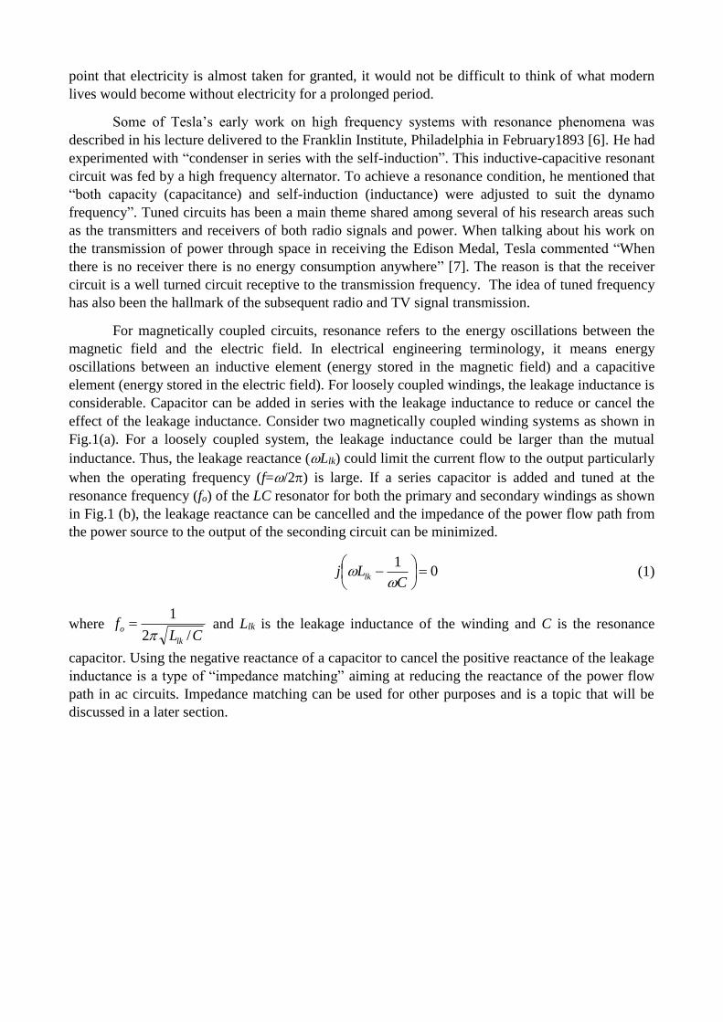
For magnetically coupled circuits, resonance refers to the energy oscillations between the
magnetic field and the electric field. In electrical engineering terminology, it means energy
oscillations between an inductive element (energy stored in the magnetic field) and a capacitive
element (energy stored in the electric field). For loosely coupled windings, the leakage inductance is
considerable. Capacitor can be added in series with the leakage inductance to reduce or cancel the
effect of the leakage inductance. Consider two magnetically coupled winding systems as shown in
Fig.1(a). For a loosely coupled system, the leakage inductance could be larger than the mutual
inductance. Thus, the leakage reactance (Llk) could limit the current flow to the output particularly
when the operating frequency (f=/2) is large. If a series capacitor is added and tuned at the
resonance frequency (fo) of the LC resonator for both the primary and secondary windings as shown
in Fig.1 (b), the leakage reactance can be cancelled and the impedance of the power flow path from
the power source to the output of the seconding circuit can be minimized.
01
CLj lk
(1)
where CL
flk
o/2
1
and Llk is the leakage inductance of the winding and C is the resonance
capacitor. Using the negative reactance of a capacitor to cancel the positive reactance of the leakage
inductance is a type of “impedance matching” aiming at reducing the reactance of the power flow
path in ac circuits. Impedance matching can be used for other purposes and is a topic that will be
discussed in a later section.
(a)
(b)
Fig.1 Equivalent circuit of (a) two magnetically coupled windings and (b) two magnetically
coupled windings with series capacitor compensation
II SOME OF TESLA’S EARLY WORK ON MAGNETIC RESONANCE
In 1893, Tesla described his high-frequency and resonance investigations in [6]. Inspired by
the work of Heinrich Hertz and Oliver Lodge, he reported several experimental setups of his WPT
study on using high-frequency oscillator for medical/therapeutic and other purposes [1]. Three of
these setups are shown in Fig.2. Fig. 2(a) shows two magnetically coupled windings (Primary
winding P and Secondary winding S). The primary winding is connected in parallel with a
condenser C (capacitor) and is fed by a high-frequency generator G. The frequency was set in the
range of 5-10 kHz. In the secondary winding, the two output terminals are labelled as T. In the
description of this setup, Tesla added that “Two plates of large surfaces, forming an adjustable
condenser, may be used for the purpose of synchronizing the secondary with the primary circuit”.
Tesla further discussed the use of resonant circuits in Fig. 2(b), in which two parallel-connected
condensers C are connected in series with the primary winding P. The two ends of the secondary
winding are connected to two sets of parallel plates tt and t’t’ of considerable surface (i.e. a form of
M12
j Llk1 j Llk2
R1 R2
M12
R1 R2
variable capacitor). The voltage and current obtained from the two output terminals T T can be
regulated by simply varying the distance between the two pairs of plates tt and t’t’ respectively. In
modern terminology, this WPT system consists of a series-resonant primary winding and a series-
resonant secondary winding.
As Tesla continued to explain the operation of the system in Fig. 2(c) in [1], he emphasized the
use of (i) high frequency, (ii) winding resistance as low as possible and (iii) the importance of
establishing synchronism between the oscillations in the primary and secondary circuits. The Q
factor for an inductor is:
R
LQ
(2)
where is the angular frequency, L is the inductance and R is the winding resistance. These
features are the factors essential to high quality factor (ie. High Q factor) and magnetic resonance of
the coupled windings. One of the short-range WPT applications demonstrated by Tesla was to
power a lamp wirelessly as shown in Fig. 3.
(a)
(b)
(c)
Fig.2 Three examples of WPT setups suggested by Tesla [1]
Fig. 3 An application of Tesla’s WPT system for powering a lamp
The contributions of Tesla to the concept of using magnetic resonance were recognized in
another memorial article published in August 1943 by L.P. Wheeler (The President of the Institute
of Radio Engineers, 1943). In [8], Wheeler states that Tesla is entitled to either distinct priority or
independent discoveries of:
a) The idea of inductive coupling between the driving and the working circuits
b) The importance of tuning both circuits, that is, the idea of an “oscillation transformer”.
c) The idea of a capacitance loaded open secondary circuit.
The idea of oscillation transformer clearly refers to the use of magnetic resonance in magnetically
coupled circuits. The use of magnetically coupled resonators operating under resonance conditions
has been a hallmark of Tesla’s WPT research.
III FACTORS RELATED TO MAGNETIC RESONANCE
Many researchers have studied various aspects of technologies related to magnetic
resonance of coupled circuits. Because of the large amount of works over the last century, this
section only cites some relevant examples. Although it does not serve as a comprehensive review, it
provides evidence that many WPT concepts considered today were studied in the past.
A The Quality (Q) Factor
While Tesla was aware of the needs for using high frequency and winding with low
resistance, Estill Green published an article about the story of Q [9] in 1955. According to Green, it
was K. S. Johnson who first used the symbol Q in 1914 as the ratio of reactance to the effective
resistance in a coil or a condenser. “Others before Johnson had made use of the ratio of reactance to
resistance for either an inductor or a capacitor (to us modem parlance). But Johnson's role was to
popularise this ratio and assign it to the contagious symbol Q.” [9]. However, it is important to note
in page 7 of [9] that “A rather spectacular recent achievement was the construction of an
experimental ferrite inductor with a Q of more than 1000.” This indicates that the idea of using an
inductor winding with Q higher than 1000 was conceived over 60 years ago.
B Analysis of Magnetically Coupled Resonant Circuits
Magnetically coupled circuits was a hot research topic in early 20th century as high
frequency radio circuits were being investigated. The mathematical analysis of magnetically
coupled oscillatory systems based on LC resonators was reviewed in 1916 by E.L. Chaffee [10]. He
studied the general case of two coupled circuits with different resonance frequencies. The effects
such as the amplitude and phase relationships of the primary and secondary current amplitudes and
their phase shift of using the frequency (i) below, (ii) at and (iii) above the resonance frequency
were examined.
C Energy Efficiency and kQ Product in Magnetically Coupled Resonant Circuits
A biological heart uses typically 20W to 35W depending on whether it is in the resting or
heavy exercise state. In 1961, John Schuder et al [11] studied power transfer for an artificial heart
and used magnetic resonance technique to transfer power wirelessly through a closed chest wall of
an animal. A series capacitor was used to compensate the leakage inductance in the secondary
winding and the operating frequency was set at the resonance frequency of the LC resonator. In
their analysis, the significance of the product of the mutual coupling coefficient k and the Q factor
of the winding was related to the power losses and thus energy efficiency of the system. It was
found that power loss is inversely proportional to the kQ product, indicating that the energy
efficiency () is proportional to the kQ product.
kQ (3a)
For magnetically coupled windings with two different Q factors,
21QQk (3b)
Equation (3) has two important meanings:
The higher the kQ product is, the higher the energy efficiency of the WPT system becomes.
For loosely coupled systems in which the coupling coefficient k is low, windings with high
Q factor should be used in order to increase the energy efficiency of the WPT systems. This
feature applies to both short-range and mid-range applications.
These two points have been known for several decades in electrical engineering community. They
are also in agreement with Tesla’s suggestions of using high frequency and windings of low
resistance.
IV NON-RADIATIVE WPT FOR SHORT-RANGE AND MID-RANGE APPLICATIONS
A Short-Range Applications Based on Magnetic Resonance
The substantial research on non-radiative WPT by Tesla and other scientists did not lead to
widespread applications of WPT in the early half of the 20th century. A major reason is the
exponential reduction of the energy efficiency with the transmission distance of a WPT system.
This issue was already pointed out in 1937 [12] and has also been reiterated recently in [13] and
[14]. As stated by Tesla, (i) high frequency operation, (ii) low winding resistance and (iii) resonance
operation are needed for efficient WPT. So it is necessary to have technologies that can operate at
high-frequency with low ac resistance.
Two technologies namely (i) winding technology with low resistance at high frequency
operation (such as Litz wires) and (ii) low-cost high frequency power conversion (such as power
electronics) have influenced the progress of WPT.
The concept of using multi-stranded wires to reduce high-frequency winding
resistance was well documented in 1917 [15]. The commercial availability of Litz
wires in the mid 1900’s enabled the emergence of WPT activities for bio-medical
applications in the 1960’s.
The maturity of power electronics in the 1980’s has provided the needed technology to
develop high-frequency power sources for modern WPT systems.
1) Examples of WPT research conducted by the bio-medical research communities
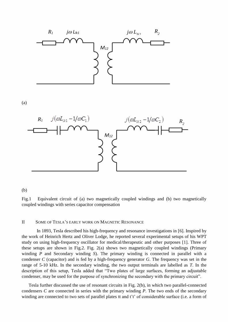
1961: John Schuder and his team reported the use of a pair of magnetically coupled circuits
for WPT through the chest wall of an animal. The circuit involved is shown in Fig. 4. The
series capacitor C was used to compensate the leakage inductance. For a chest wall
thickness of 3 cm, the magnetically coupled circuit was operated at 400 kHz corresponding
to the resonance frequency of the secondary circuit. It was stated in [11] that Litz wire was
used in this project to reduce the ac winding resistance. The windings were made in a spiral
form with inner diameter of 1.5 cm and an outer diameter of 4cm. The coupling coefficient k
was 0.25 and the kQ product is 50 (i.e. Q factor = 200). Short-term power of 50W – 69W
was successfully transmitted.
Fig. 4 Magnetically coupled circuit with a resonant tank in the receiver coil used in 1961
[11]
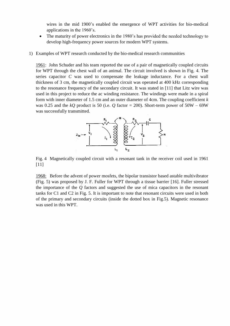
1968: Before the advent of power mosfets, the bipolar transistor based astable multivibrator
(Fig. 5) was proposed by J. F. Fuller for WPT through a tissue barrier [16]. Fuller stressed
the importance of the Q factors and suggested the use of mica capacitors in the resonant
tanks for C1 and C2 in Fig. 5. It is important to note that resonant circuits were used in both
of the primary and secondary circuits (inside the dotted box in Fig.5). Magnetic resonance
was used in this WPT.
Fig. 5 Transistor-based astable multivibrator used in 1968 for WPT [16]
1971: With a pair of much larger spiral coil made of Litz wires, John Schuder’s team
continued their research by transferring 1 kW through the skin of a dog (thickness of 7.5
mm) [17]. It is interesting to note that they have considered the tissue conductivity,
inductance and capacitance under an operating frequency of 480 kHz. The circuit structure
is generally the same as that shown in Fig.4. The magnetically coupled circuits were
operated in resonance mode.
2) Examples of WPT research conducted by the power electronics research communities
With the availability of power mosfets and resonant switching converters in the
1980s [18]-[20], research into the driving techniques and circuits for WPT system started to
appear. The examples listed below adopt magnetic resonance based on LC resonators.
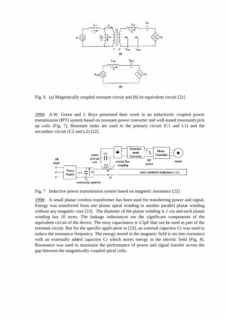
1990: Bo Cho used a pair of magnetically coupled circuits operating at resonance mode for
a transcutaneous energy transmission system as shown in Fig. 6 [21]. The coupling was
fairly loose with a coupling coefficient of k = 0.1.For an output power of 48W, an energy
efficiency of 72% was achieved for an operating frequency of about 53 kHz. It should be
noted that the “impedance matching” in the resonant tanks was implemented to reduce the
effects of leakage inductance in the primary and secondary circuits.
Fig. 6 (a) Magnetically coupled resonant circuit and (b) its equivalent circuit [21]
1994: A.W. Green and J. Boys presented their work in an inductively coupled power
transmission (IPT) system based on resonant power converter and well-tuned (resonant) pick
up coils (Fig. 7). Resonant tanks are used in the primary circuit (C1 and L1) and the
secondary circuit (C2 and L2) [22].
Fig. 7 Inductive power transmission system based on magnetic resonance [22]
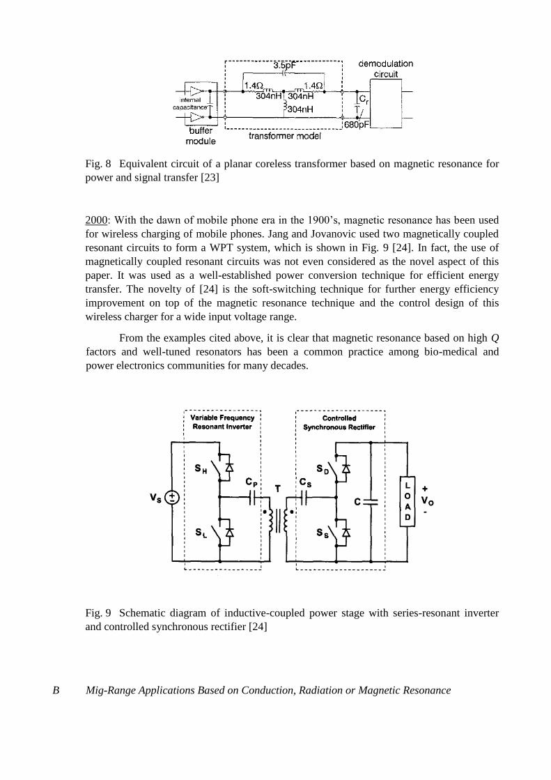
1998: A small planar coreless transformer has been used for transferring power and signal.
Energy was transferred from one planar spiral winding to another parallel planar winding
without any magnetic core [23]. The diameter of the planar winding is 1 cm and each planar
winding has 10 turns. The leakage inductances are the significant components of the
equivalent circuit of the device. The stray capacitance is 3.5pF that can be used as part of the
resonant circuit. But for the specific application in [23], an external capacitor Cr was used to
reduce the resonance frequency. The energy stored in the magnetic field is set into resonance
with an externally added capacitor Cr which stores energy in the electric field (Fig. 8).
Resonance was used to maximize the performance of power and signal transfer across the
gap between the magnetically coupled spiral coils.
Fig. 8 Equivalent circuit of a planar coreless transformer based on magnetic resonance for
power and signal transfer [23]
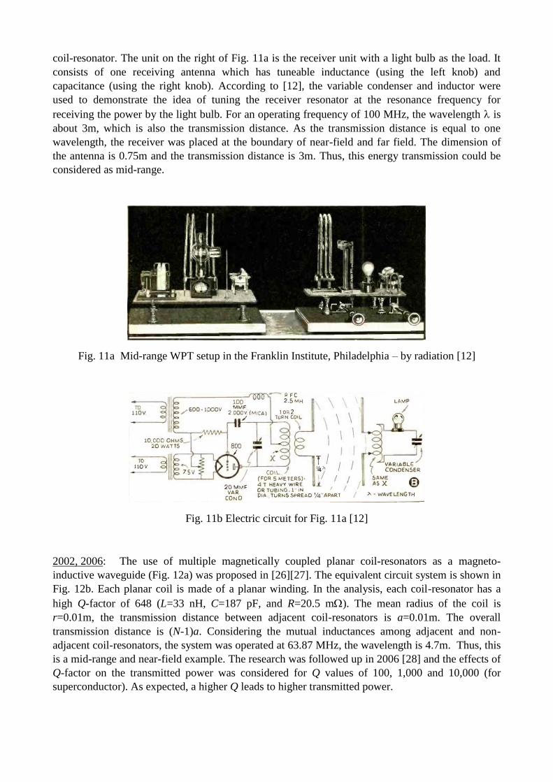
2000: With the dawn of mobile phone era in the 1900’s, magnetic resonance has been used
for wireless charging of mobile phones. Jang and Jovanovic used two magnetically coupled
resonant circuits to form a WPT system, which is shown in Fig. 9 [24]. In fact, the use of
magnetically coupled resonant circuits was not even considered as the novel aspect of this
paper. It was used as a well-established power conversion technique for efficient energy
transfer. The novelty of [24] is the soft-switching technique for further energy efficiency
improvement on top of the magnetic resonance technique and the control design of this
wireless charger for a wide input voltage range.
From the examples cited above, it is clear that magnetic resonance based on high Q
factors and well-tuned resonators has been a common practice among bio-medical and
power electronics communities for many decades.
Fig. 9 Schematic diagram of inductive-coupled power stage with series-resonant inverter
and controlled synchronous rectifier [24]
B Mig-Range Applications Based on Conduction, Radiation or Magnetic Resonance
Since Tesla described the use of WPT for powering a lighting device (Fig. 3), most of the 2-
coil WPT systems have been designed for short-range applications. In 1937, an interesting mid-
range 3-coil WPT system for powering a lamp was described [12]. Recently, several multiple-coil
WPT systems have been reported. Before examples of mid-range WPT are described in this section,
it is necessary to introduce the concepts of near-field coupling and mid-range WPT.
Near-field distance is related to the wavelength of the electromagnetic wave and is usually
defined as a distance within one wavelength in a general sense. In a stricter sense, a
distance of /2 or 0.159 is considered as the range for near-field coupling.
The concept of short-range and mid-range WPT is related to the ratio of the transmission
distance d and the coil dimension of the transmitter coil. In general, short-range coupling
refers to a transmission distance less than or equal to the dimension of the transmitter
structure. For a circular transmitter coil, rd 2 where r is the radius of the coil. Mid-range
usually refers to a distance of several times the dimension of the transmitter structure.
1900: One of the early WPT systems suggested by Tesla for mid-range application is shown in
Fig. 10. It is a 4-coil system. The transmitter side has a driving loop C coupled to a transmitter coil
A which significantly steps up the voltage for an elevated terminal D. Similarly, the receiver side
has a load loop C’ coupled to the receiver coil A’ which is connected to an elevated terminal D’.
Through electrical oscillation, current is discharged through air between D and D’ by conduction.
Fig. 10 A diagram of one of Tesla’s wireless power experiments – by conduction [25]
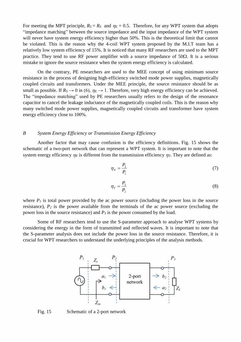
1937: In August 1937, a cover story appeared in Short Wave & Television Magazine [12]
regarding an experiment deploying a Radio-frequency Power Transmitter to wirelessly power a
20W lamp over a distance of 10 ft (i.e. 3m). The operating frequency was 100 MHz. An
experimental setup (Fig. 11a) was installed in the Franklin Institute, Philadelphia (where Tesla had
given the lecture). The unit on the left of Fig. 11a is the transmitter unit. This system is a 3-coil
system and its circuit is shown in Fig. 11b. It includes a first coil magnetically coupled to a second
coil that is used as an antenna. The transmitter circuit involves an oscillator driving a tuneable LC
coil-resonator. The unit on the right of Fig. 11a is the receiver unit with a light bulb as the load. It
consists of one receiving antenna which has tuneable inductance (using the left knob) and
capacitance (using the right knob). According to [12], the variable condenser and inductor were
used to demonstrate the idea of tuning the receiver resonator at the resonance frequency for
receiving the power by the light bulb. For an operating frequency of 100 MHz, the wavelength is
about 3m, which is also the transmission distance. As the transmission distance is equal to one
wavelength, the receiver was placed at the boundary of near-field and far field. The dimension of
the antenna is 0.75m and the transmission distance is 3m. Thus, this energy transmission could be
considered as mid-range.
Fig. 11a Mid-range WPT setup in the Franklin Institute, Philadelphia – by radiation [12]
Fig. 11b Electric circuit for Fig. 11a [12]
2002, 2006: The use of multiple magnetically coupled planar coil-resonators as a magneto-
inductive waveguide (Fig. 12a) was proposed in [26][27]. The equivalent circuit system is shown in
Fig. 12b. Each planar coil is made of a planar winding. In the analysis, each coil-resonator has a
high Q-factor of 648 (L=33 nH, C=187 pF, and R=20.5 m). The mean radius of the coil is
r=0.01m, the transmission distance between adjacent coil-resonators is a=0.01m. The overall
transmission distance is (N-1)a. Considering the mutual inductances among adjacent and non-
adjacent coil-resonators, the system was operated at 63.87 MHz, the wavelength is 4.7m. Thus, this
is a mid-range and near-field example. The research was followed up in 2006 [28] and the effects of
Q-factor on the transmitted power was considered for Q values of 100, 1,000 and 10,000 (for
superconductor). As expected, a higher Q leads to higher transmitted power.
(a)
(b)
Fig. 12 (a) Magneto-inductive waveguide based on coil-resonators (- by magnetic resonance) and
(b) its equivalent circuit [26]
2007: In 2007, a group of physicists from M.I.T. announced their project of wirelessly powering a
60W light bulb over a distance of 2m [29][30]. The group emphasized the use of magnetic
resonance instead of magnetic induction. The media publicity following their announcement has
undoubtedly sparked off a lot of interest in WPT. Their work is based on a 4-coil system in which
there are two resonators and two coupled coils as shown in Fig. 13(a). The use of a coupled coil to
the resonator is similar to the transmitter stage of the 1937 experiment in Fig. 11(b). The analysis
was conducted with the coupled mode theory. They identified the “strong coupling” regime [29] as:
121 (4)
where the symbol is related to the mutual coupling coefficient k as k
2
;
1
12Q
and
2
22Q
are the intrinsic loss rates of the first resonator and the second resonator respectively.
According to [29], this condition of (4) is “a regime of operation that has not been studied
extensively”. However, the term 21 of the coupled mode theory is equal to 21QQk in
electric circuit theory, where k is the mutual coefficient between the two coupled coils; Q1 and Q2
are the Q-factors of the two coil-resonators. Thus, 121 simply means 121 QQk
which has been a well-known concept in electrical engineering for several decades [16].
For mid-range application, the transmission distance is relatively large and so the mutual
coupling coefficient k is relatively small. For a small k, using a high Q factor for each resonator
would increase the energy efficiency as described in (3b). This point has been well known in
electrical engineering for a century [1]. Regarding the suggestion of using resonance for efficient
energy transfer [29][30], David Schneider commented in the IEEE Spectrum [31] that “It’s not a
new idea: Tesla’s eponymous coils use that very same principle”.
Fig. 13 (a) Schematic of the 4-coil WPT system proposed in [29] – by magnetic resonance and
(b) its equivalent circuit
The 4-coil system in [29][30] has been analysed by several research groups using standard
electric circuit theory [32]-[34]. Reference [32] provides a detailed analysis and an equivalent
circuit of this system (Fig. 13). Basically, it shows that the operating principle of the 4-coil setup in
[29][30] can be described by standard coupled circuit equations. The equivalent circuit is shown in
Fig. 13(b). With an operating frequency at about 10 MHz, the stray capacitance of the resonator coil
can be used as the resonance capacitor. The essence of this 4-coil WPT system lies in the provision
of the two extra mutual inductance terms of the coupled loops (i.e. k12 and k34). The authors of [32]
point out that the 4-coil system of [29][30] transmits power based on the impedance matching of the
source impedance and the input impedance of the entire 4-coil WPT system. To achieve such
impedance matching for maximum power transfer (i.e. Zo=Zin in Fig. 13(b)), the following
condition has to be met:
123
3412 k
kk (5)
The availability of k12 and k34 provides the flexibility in meeting this condition. For example, for a
mid-range transmission distance between the two coupled resonators, their mutual coupling
coefficient k23 is small (e.g. 0.01), by adjusting k12 and k34 to be 0.1, the condition of (5) can be met.
The flexibility of tuning the coupling coefficients for satisfying (5) is a contribution of this 4-coil
system, although such system involves no new scientific principle. But this is done at the expense
of the system energy efficiency. Its system energy efficiency is 15%, meaning that an input power
of 400W is needed to power a 60W light bulb. Therefore, the 4-coil WPT system proposed in [29]
and [30] is unsuitable for most applications in which energy efficiency is a concern. It may be
useful for very low-power devices with charging power of less than one Watt. The low energy
efficiency issue and mid-range WPT will be further addressed in the next sections.
V MAXIMUM ENERGY EFFICIENCY (MEE) OR MAXIMUM POWER TRANSFER (MPT)
With many research papers on WPT published in recent years, one may ask a question of
which WPT technique should be used. The fact that Radio-Frequency (RF) researchers and Power
Electronics (PE) researchers use different approaches and terminologies is a source of confusion.
This important question has been addressed in a critical review [35],[36], which classifies all WPT
systems and techniques to be under either (i) the Maximum Energy Efficiency (MEE) Principle or
(ii) Maximum Power Transfer (MPT) principle. Fig.14 (a) shows a basic circuit of a load powered
by an ac power source. The source impedance is RS=jXS and the load impedance is RL+jXL. The
normalized power output and efficiency curve of this circuit are plotted in Fig. 14(b). It is very
important to note that the operating point of MEE is different from that of MPT.
Fig. 14 (a) A basic ac electric circuit and (b) the corresponding energy efficiency and output power
curves.
A The Serious Problem of Ignoring Source Resistance in WPT
Based on the “maximum power transfer theorem”, maximum power can be transferred to the
load when RS = RS and XS = -XL. Under this MPT condition, half of the total power from the ac
power source will be dissipated in the source resistance RS. The ideal system energy efficiency is a
ratio of the output power Pout and input power Pin:
LS
L
LS
L
in
out
ERR
R
RRi
Ri
P
P
2
2
(6)
For meeting the MPT principle, RS = RS and E = 0.5. Therefore, for any WPT system that adopts
“impedance matching” between the source impedance and the input impedance of the WPT system
will never have system energy efficiency higher than 50%. This is the theoretical limit that cannot
be violated. This is the reason why the 4-coil WPT system proposed by the M.I.T team has a
relatively low system efficiency of 15%. It is noticed that many RF researchers are used to the MPT
practice. They tend to use RF power amplifier with a source impedance of 50. It is a serious
mistake to ignore the source resistance when the system energy efficiency is calculated.
On the contrary, PE researchers are used to the MEE concept of using minimum source
resistance in the process of designing high-efficiency switched mode power supplies, magnetically
coupled circuits and transformers. Under the MEE principle, the source resistance should be as
small as possible. If RS → 0 in (6), E → 1. Therefore, very high energy efficiency can be achieved.
The “impedance matching” used by PE researchers usually refers to the design of the resonance
capacitor to cancel the leakage inductance of the magnetically coupled coils. This is the reason why
many switched mode power supplies, magnetically coupled circuits and transformer have system
energy efficiency close to 100%.
B System Energy Efficiency or Transmission Energy Efficiency
Another factor that may cause confusion is the efficiency definitions. Fig. 15 shows the
schematic of a two-port network that can represent a WPT system. It is important to note that the
system energy efficiency E is different from the transmission efficiency T. They are defined as:
1
3
P
PE (7)
2
3
P
PT (8)
where P1 is total power provided by the ac power source (including the power loss in the source
resistance), P2 is the power available from the terminals of the ac power source (excluding the
power loss in the source resistance) and P3 is the power consumed by the load.
Some of RF researchers tend to use the S-parameter approach to analyse WPT systems by
considering the energy in the form of transmitted and reflected waves. It is important to note that
the S-parameter analysis does not include the power loss in the source resistance. Therefore, it is
crucial for WPT researchers to understand the underlying principles of the analysis methods.
Fig. 15 Schematic of a 2-port network
C Comparison of MEE and MPT
With the understanding of the MEE and MPT principles, one can easily determine which
approach should be adopted for a specific application. The features of the two principles are
summarized in Table I.
MEE MPT
Impedance matching To design the resonance
capacitor to compensate the
leakage inductance
To match the input
impedance of the
WPT system with the
source impedance
System efficiency Can be higher than 50% 50%
Source resistance As low as possible (RS→0) Dependent on the
power source
Suitable power level 1W < 1W
Applications Energy efficiency is a
priority
Energy efficiency is
not a priority
Feature of a 2-coil
system
High efficiency for short-
range, but very low
efficiency for mid-range
applications
Low efficiency for
both short- and mid-
range applications
Feature of a 4-coil
system based on two
resonators and two
coupled coils [28][29]
Maximized
transmission distance
at the expense of
energy efficiency.
Feature of multi-coil
system based on relay
resonators [35][36]
A good compromise
between energy efficiency
and transmission distance.
VI NEW HEALTH AND SAFETY ISSUES FOR MID-RANGE WPT
While short-range WPT systems such as the wireless charging pads for portable consumer
electronics usually use electromagnetic shields to confine the magnetic flux in order to avoid flux
leakage, mid-range WPT systems may have to deal with new safety and health issues. New health
concerns have recently been raised by quantum biologists. In 2014, practical evidence was
presented in [37] to show that even a weak magnetic field of 10µT at 7 MHz could enhance cell
proliferation. (Note: The static magnetic field of the earth is about 45 µT.) Apparently, magnetic
field at 7 MHz could influence the electronic spins of cells to form radicals. The authors of [37]
criticize the existing safety regulations which only consider the thermal stress on cells based on the
specific absorption rate (Watt per kilogram of tissue) as inadequate. In their conclusion, they
comment that “In contrast to the spin-pair mechanism, specific absorbed radiation (SAR)
measurements of macroscopic tissue heating represent a naïve approach to bio-magnetic RF-
interactions because it ignores nanoscale physics and spin chemistry, which can potentially have
profound biological effects.” As a response to [37], the authors of [38] provide possible
explanations for observed changes in growth rates of cancer cells and radical concentration upon
exposures to magnetic fields below the ICES and ICNIRP reference levels. Perhaps it is time for
international regulatory bodies to re-examine the existing health and safety regulations in view of
the new evidence because 7 MHz is close to the ISM band of 6.78 MHz (which is an operating
frequency being considered by some companies for WPT product developments).
For mid-range applications, one challenge is to shield any foreign lossy object in the path of
the WPT. In 2012, there was a suggestion of using a conducting surface and a layer of magnetic
material to shape the magnetic field [39] in order to avoid lossy objects. It should be noted that the
use of a double-layer electromagnetic shield comprising a layer of conducting material and a layer
of soft magnetic materials for confining the magnetic field was previously described in 2002 [40]
and [41]. If weak magnetic field of frequency close to 7 MHz could induce health hazards, not only
lossy objects but also human bodies should be shielded from such magnetic field.
VII CONCLUSIONS
This article traces some historical works of WPT and shows that many important concepts
such as high Q factor, magnetic resonance, magnetically coupled resonators are not recent
developments. Many research pioneers over the past century have laid down these scientific
principles for WPT. In particular, magnetic resonance for efficient wireless energy transfer has been
widely used in many WPT projects for many decades. The classification of the maximum energy
efficiency principle and maximum power transfer principle for WPT systems should make it easy
for researchers and engineers to distinguish the nature of different WPT systems and help them
decide which principle should be adopted for a specific application. The importance of including
the power loss in the source resistance of the power source is emphasized because it is a crucial
factor that determines the overall energy efficiency of the entire system. It is important to note that
essentially all of the transmitter circuits and receiver circuits specified in the Qi standard [42] are
magnetically coupled resonant circuits. The use of magnetic resonance including the maximization
of the 21QQk product for efficient energy transfer has been common practice in electrical
engineering for many decades. Recent concerns about biological effects of low-level 7M Hz
magnetic field on the cell proliferation raised by the quantum biologists should be taken seriously as
such biological effects may have safety and health implications on future mid-range WPT
applications. Short-range WPT systems usually have the benefit of having the magnetic flux
enclosed by EM shields, and so do not have such EM field exposure issues.
References
[1] Nikola Tesla, “High frequency oscillators for electro-therapeutic and other purposes”, The
Electrical Engineer. Vol. XXVI. November 17, 1898. No. 550.
[2] Nikola Tesla, “Transmission of electrical energy without wire”, Electrical World and
Engineer, March 5, 1904 [online] www.tfcbooks.com/tesla/
[3] M. Hutin and M. Leblanc, “Transformer system for electric railways”, US patent 527 857,
Oct. 23, 1894
[4] “Nikola Tesla 1857 – 1943”, May 1943, Proceedings of the I.R.E., pp: 194
[5] R. Lomas, “The Man Who Invented the Twentieth Century – Nikola Tesla – Forgotten
Genius of Electricity”, U.K., Headline Book Publishing, 1999
[6] Nikola Tesla, “On light and other high frequency phenomena”, Lecture Delivered before the
Franklin Institute, Philadelphia, February 1893, and before the National Electric Light
Association, St. Louis, March 1893. [online] www.tfcbooks.com/tesla/