Page 1
MAHARASHTRA STATE BOARD OF TECHNICAL EDUCATION (Autonomous)
(ISO/IEC - 27001 - 2005 Certified) _____________________________________________________________________________________________
1
Winter – 15 EXAMINATIONS
Subject Code: 17472 Model Answer
Important Instructions to examiners:
1) The answers should be examined by key words and not as word-to-word as given in the answer scheme.
2) The model answer and the answer written by candidate may vary but the examiner may try to assess the understanding level of the candidate.
3) The language errors such as grammatical, spelling errors should not be given more Importance (Not applicable for subject English and Communication Skills.
4) While assessing figures, examiner may give credit for principal components indicated in the figure. The figures drawn by candidate and model answer may vary. The examiner may give credit for any equivalent figure drawn.
5) Credits may be given step wise for numerical problems. In some cases, the assumed constant values may vary and there may be some difference in the candidate’s answers and model answer.
6) In case of some questions credit may be given by judgment on part of examiner of relevant answer based on candidate’s understanding.
7) For programming language papers, credit may be given to any other program based on equivalent concept.
Page 2
MAHARASHTRA STATE BOARD OF TECHNICAL EDUCATION (Autonomous)
(ISO/IEC - 27001 - 2005 Certified) _____________________________________________________________________________________________
2
17472
Q1. A) Attempt any SIX the following (12)
i. State the sampling theorem
ANS: ( statement 2 M )
A continuous time signal x(t) can be completely represented in its sampled form and
recovered back from the sampled form if the sampling frequency fs >= 2fm, where fm
is the maximum frequency of the continuous signal.
ii. Define geostationary satellite. State its two advantages.
ANS:
( Define- 1mks, Any 2 advantages – 1mks)
Geostationary satellite: The orbit in which satellite completes one revolution around the earth in
24 Hrs, the orbit is called as geostationary satellite. Satellite uses synchronous orbit is called
geosynchronous satellite.
Advantages:
1) ationary in respect to given earth station.
Consequently, expensive tracking equipment is not required at the earth stations.
2) time. The shadow of a satellite includes all the earth station that have a line of sight path to it
and lie within the radiation patterns within the antennas.
3) Consequently, there are no transmission breaks due to switching times.
4) The effects of Doppler shift are negligible.
iii. Draw the circuit of AM demodulator. Draw its input and output waveforms.
ANS:-( Circuit diagram- 1 mks,waveforms- 1mks)
iv. Draw the block diagram of FDM generation.
ANS: ( Proper diagram – 2mks)
Page 3
MAHARASHTRA STATE BOARD OF TECHNICAL EDUCATION (Autonomous)
(ISO/IEC - 27001 - 2005 Certified) _____________________________________________________________________________________________
3
OR
v. Draw sketches of ring and mesh network topology.
ANS:- ( Each sketch- 1 mks)
Page 4
MAHARASHTRA STATE BOARD OF TECHNICAL EDUCATION (Autonomous)
(ISO/IEC - 27001 - 2005 Certified) _____________________________________________________________________________________________
4
vi. State and explain Snell‟s law with neat diagram.
ANS: ( Statrement – 1 mks, ex[lanation- 1 mks)
It states that , incident angle θo is related to exit angle θ1 by the relation
no sine θo = n1 sine θ1
no /n1= sine θ0/ sine θ1
Explanation- Angle of incidence should be equal to angle of reflection.
vii. Define TDM and WDM.
ANS: ( Each proper definition- 1 mks)
Time-division multiplexing (TDM) :- It is multiplexing technique in which signals from multiple
source are send using single link separated by time quanta.
Wave- Division Multiplexing (WDM) : WDM is an analog multiplexing techniques to combine
optical signal. Very narrow bands of light from different sources are combined to make wider band
of light and at the receivers, the signals are separated by the demultiplexer.
Page 5
MAHARASHTRA STATE BOARD OF TECHNICAL EDUCATION (Autonomous)
(ISO/IEC - 27001 - 2005 Certified) _____________________________________________________________________________________________
5
viii. Give the classification of communication system.
ANS: Communication system is classified into two types ( 2 mks)
1. Wired / line communication.
2. Wire less / radio communication.
Q. 1). B)-Attempt any two 8
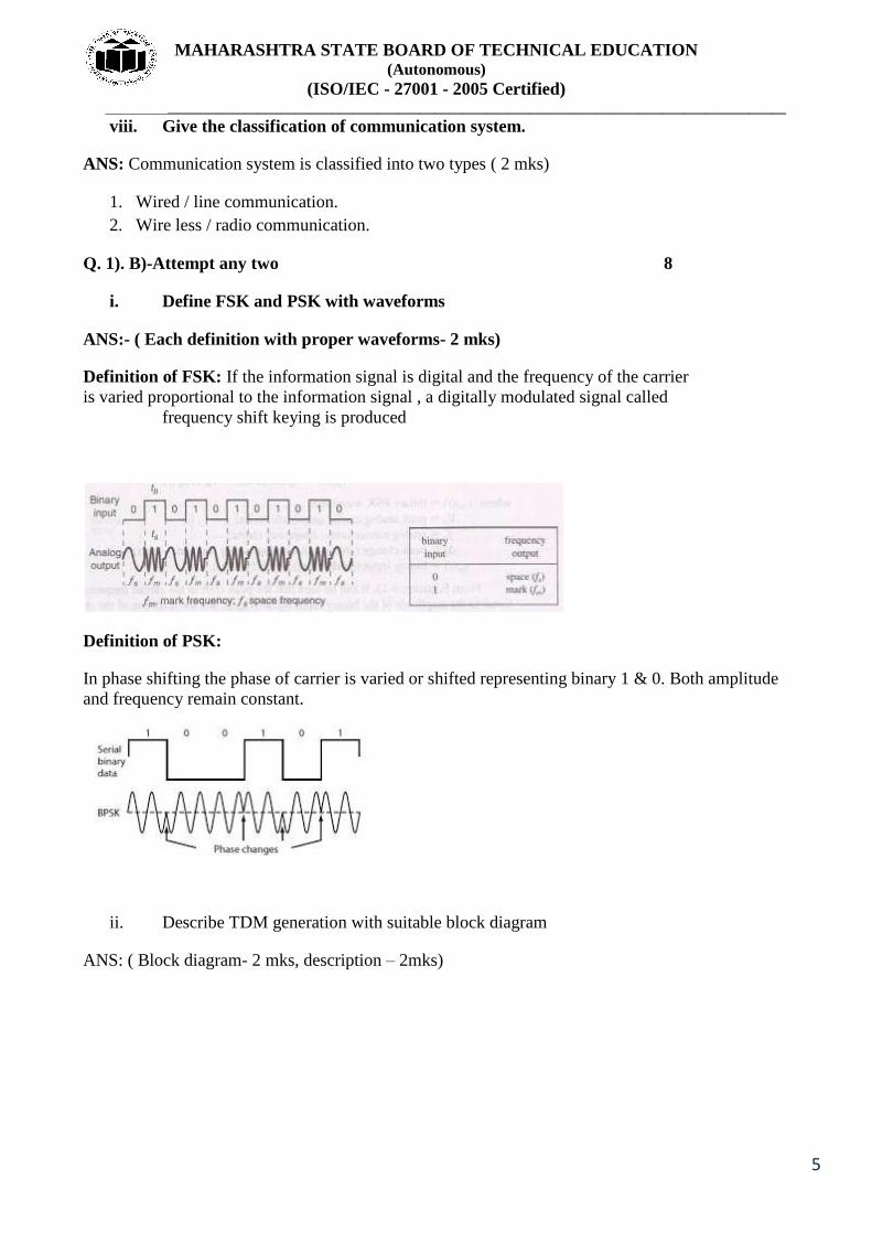
i. Define FSK and PSK with waveforms
ANS:- ( Each definition with proper waveforms- 2 mks)
Definition of FSK: If the information signal is digital and the frequency of the carrier
is varied proportional to the information signal , a digitally modulated signal called
frequency shift keying is produced
Definition of PSK:
In phase shifting the phase of carrier is varied or shifted representing binary 1 & 0. Both amplitude
and frequency remain constant.
ii. Describe TDM generation with suitable block diagram
ANS: ( Block diagram- 2 mks, description – 2mks)
Page 6
MAHARASHTRA STATE BOARD OF TECHNICAL EDUCATION (Autonomous)
(ISO/IEC - 27001 - 2005 Certified) _____________________________________________________________________________________________
6
iii. Draw block diagram of electronic communication system.
Explain the function of each block.
ANSBlock diagram- 2 mks, explanation- 2 mks)
Explanation-
Page 7
MAHARASHTRA STATE BOARD OF TECHNICAL EDUCATION (Autonomous)
(ISO/IEC - 27001 - 2005 Certified) _____________________________________________________________________________________________
7
Q2. Attempt any FOUR of the following 16
a. Give four advantages of pulse modulation over analog modulation.
ANS:( any 4 advantages- 4 mks)
Advantages:
1)
2)
3)
4)
5)
6)
b. Define modulation. State the need of modulation.(any 3 points)
ANS: ( Definition – 1 mks, Need 3 points- 3 mks)
Ans:-Modulation:- The process in which any one parameter of a high frequency carrier signal
( i.e. either amplitude,frequency or phase)is varied in accordance with the instantaneous value of the
modulating signal ,keeping the other two parameters constant.
Need of modulation
1. To reduce the height of the antenna.
2. To avoid the mixing of the signals.
3. To increase the range of
ommunication.
4. To make multiplexing possible.
5. To improve quality of reception
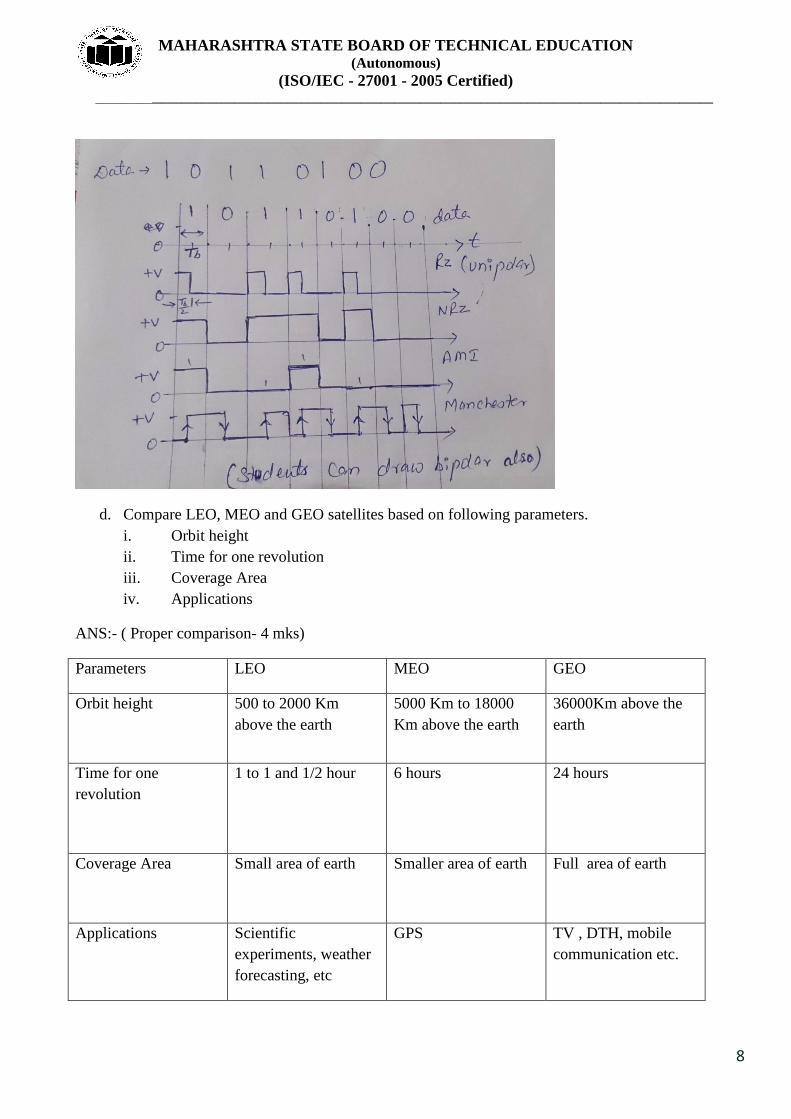
c. Encode the binary data stream 100110100 into Return to Zero.(RZ), Non-return to Zero
(NRZ), AMI and Manchester code.
ANS: ( Each code – 1mks)
Page 8
MAHARASHTRA STATE BOARD OF TECHNICAL EDUCATION (Autonomous)
(ISO/IEC - 27001 - 2005 Certified) _____________________________________________________________________________________________
8
d. Compare LEO, MEO and GEO satellites based on following parameters.
i. Orbit height
ii. Time for one revolution
iii. Coverage Area
iv. Applications
ANS:- ( Proper comparison- 4 mks)
Parameters LEO MEO GEO
Orbit height
500 to 2000 Km
above the earth
5000 Km to 18000
Km above the earth
36000Km above the
earth
Time for one
revolution
1 to 1 and 1/2 hour 6 hours 24 hours
Coverage Area
Small area of earth Smaller area of earth Full area of earth
Applications
Scientific
experiments, weather
forecasting, etc
GPS TV , DTH, mobile
communication etc.
Page 9
MAHARASHTRA STATE BOARD OF TECHNICAL EDUCATION (Autonomous)
(ISO/IEC - 27001 - 2005 Certified) _____________________________________________________________________________________________
9
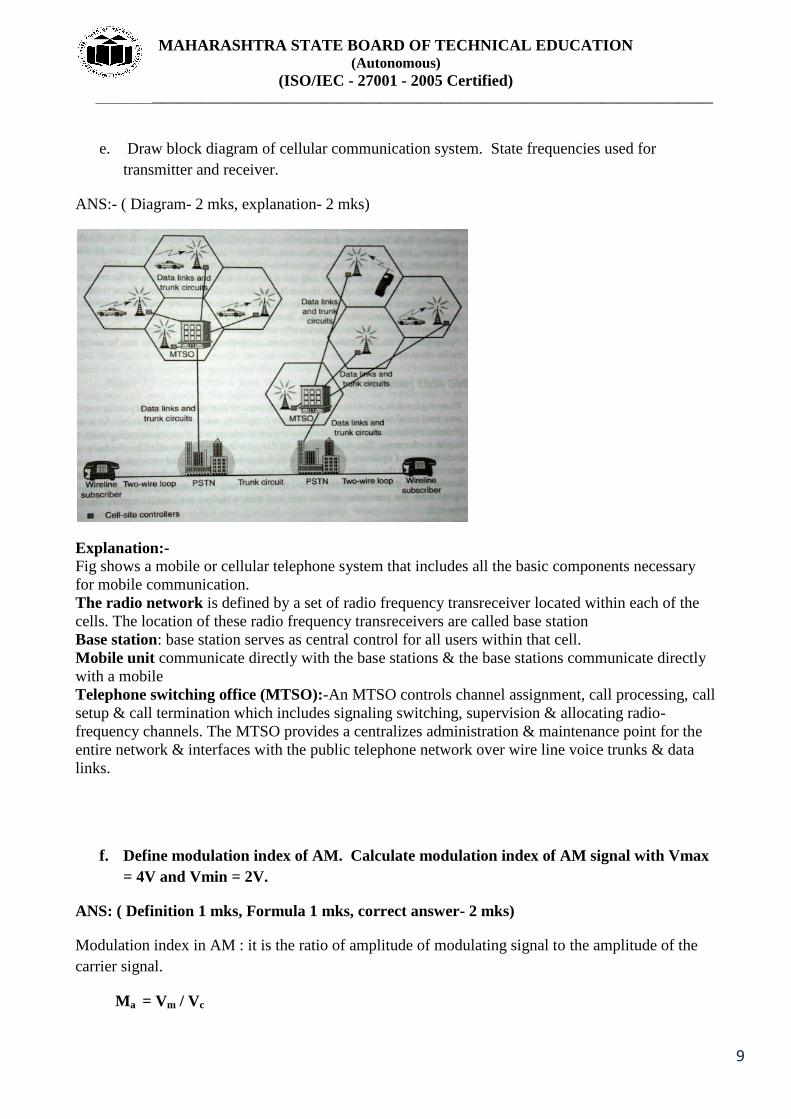
e. Draw block diagram of cellular communication system. State frequencies used for
transmitter and receiver.
ANS:- ( Diagram- 2 mks, explanation- 2 mks)
Explanation:- Fig shows a mobile or cellular telephone system that includes all the basic components necessary
for mobile communication.
The radio network is defined by a set of radio frequency transreceiver located within each of the
cells. The location of these radio frequency transreceivers are called base station
Base station: base station serves as central control for all users within that cell.
Mobile unit communicate directly with the base stations & the base stations communicate directly
with a mobile
Telephone switching office (MTSO):-An MTSO controls channel assignment, call processing, call
setup & call termination which includes signaling switching, supervision & allocating radio-
frequency channels. The MTSO provides a centralizes administration & maintenance point for the
entire network & interfaces with the public telephone network over wire line voice trunks & data
links.
f. Define modulation index of AM. Calculate modulation index of AM signal with Vmax
= 4V and Vmin = 2V.
ANS: ( Definition 1 mks, Formula 1 mks, correct answer- 2 mks)
Modulation index in AM : it is the ratio of amplitude of modulating signal to the amplitude of the
carrier signal.
Ma = Vm / Vc
Page 10
MAHARASHTRA STATE BOARD OF TECHNICAL EDUCATION (Autonomous)
(ISO/IEC - 27001 - 2005 Certified) _____________________________________________________________________________________________
10
Ma = Vmax - V min/ Vmax + V min
Ma = 4-2/ 4+2
Ma = 0.33 or 33%
Q3. Attempt any FOUR of the following (16)
a. Draw the circuit diagram of PWM generator and explain its working with waveform.
ANS:-( Circuit diagram- 2 mks, Explanation- 1mks, Waveforms- 1 mks)
Working:
to the inverting The modulating signal is applied to the non-inverting
The comparator output will remain high as long as the
instantaneous amplitude of modulating signal is
a PWM signal at the comparator output.
Page 11
MAHARASHTRA STATE BOARD OF TECHNICAL EDUCATION (Autonomous)
(ISO/IEC - 27001 - 2005 Certified) _____________________________________________________________________________________________
11
NOTE: Only PWM waveform is required
b. Draw the block diagram of QPSK generator. Stare functions of each block.
ANS::- ( Block diagram- 2 mks, Explanation- 2 mks)
Page 12
MAHARASHTRA STATE BOARD OF TECHNICAL EDUCATION (Autonomous)
(ISO/IEC - 27001 - 2005 Certified) _____________________________________________________________________________________________
12
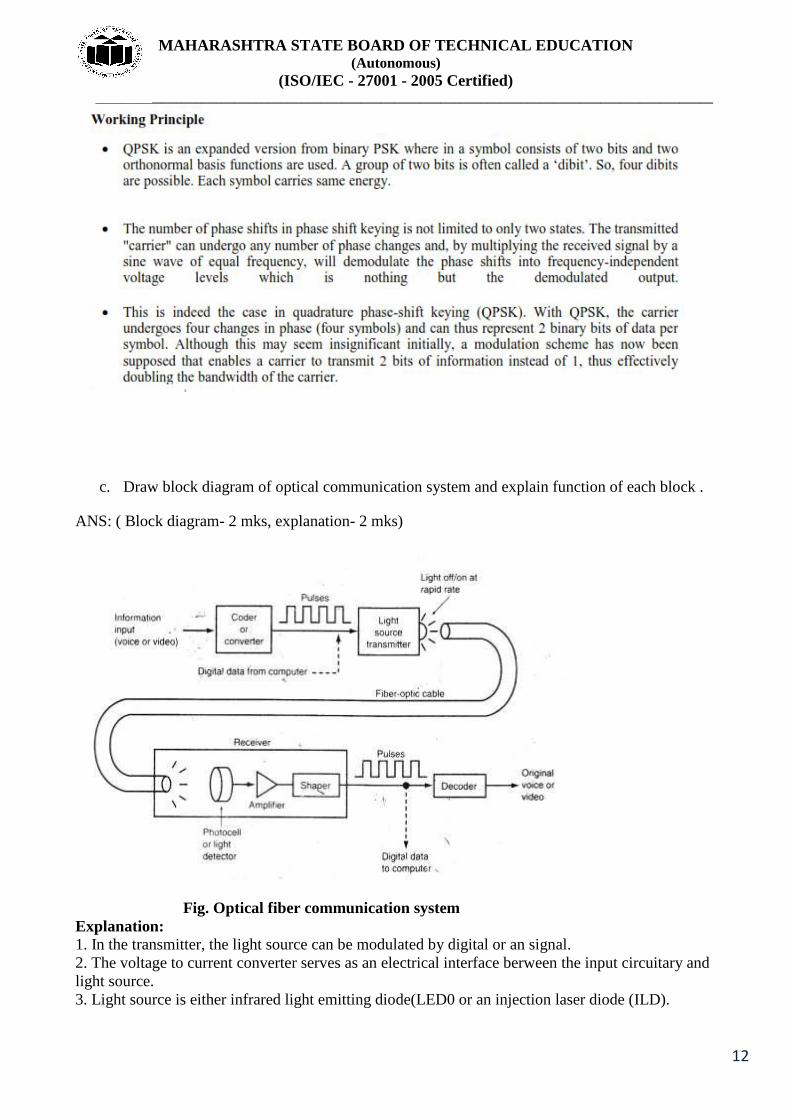
c. Draw block diagram of optical communication system and explain function of each block .
ANS: ( Block diagram- 2 mks, explanation- 2 mks)
Fig. Optical fiber communication system
Explanation:
1. In the transmitter, the light source can be modulated by digital or an signal.
2. The voltage to current converter serves as an electrical interface berween the input circuitary and
light source.
3. Light source is either infrared light emitting diode(LED0 or an injection laser diode (ILD).
Page 13
MAHARASHTRA STATE BOARD OF TECHNICAL EDUCATION (Autonomous)
(ISO/IEC - 27001 - 2005 Certified) _____________________________________________________________________________________________
13
4. The amount of light emitted by either an LED or ILD is proportional to the amount of drive
current.
5. Thus, the voltage to current converter converts an input signal voltage to current that is used to
drive the light source.
6. The light outputted by the light source is directly proportional to the magnitude of the input
voltage.
7. The source to fiber coupler is a mechanical interface. It‟s function is to couple light emitted by
the light source into the optical fiber cable.
8. The optical fiber consists of a glass or plastic fiber core surrounded by a cladding and then
encapsulated in a protective jacket.
9. The fiber to light detector coupling device is also a mechanical coupler.
10. It‟s function is to couple as much light as possible from the fiber cable into the light detector.
11. The light detector is generally a PIN diode or phototransistor.
12. All three of these devices convert light energy to current.
13. The current to voltage converter is required to produce an output voltage proportional to the
original source information.
d. Draw the block diagram of satellite communication system. State any four applications of
satellite.
ANS: ( Block diagram- 2 mks, any 4 applications- 2 mks)
Applications-1) Remote sensing
2) Metrological application
3) Military application
4) Scientific and technological applications.
Page 14
MAHARASHTRA STATE BOARD OF TECHNICAL EDUCATION (Autonomous)
(ISO/IEC - 27001 - 2005 Certified) _____________________________________________________________________________________________
14
e. Explain co channel and adjacent channel interference in mobile communication system.
ANS:- (Each – 2 mks)
Co-channel Interference is a crosstalk from two different radio transmitters using the same
frequency. Or interference in nearby channels having same frequency
Co-channel interference can be avoided by using
1. proper frequency planning.
2. Increasing distance between two co-channels
Adjacent channel interference:
Interference resulting from signals which are close in frequency to the desired signal is called
adjacent channel
interference.
The adjacent channel interference can be reduced by
1) Careful filtering
2) Careful channel assignment.
3 ) adjacent channels
in a cell
4) base station will be too close to each other in the frequency domain and this will increase the
interference.
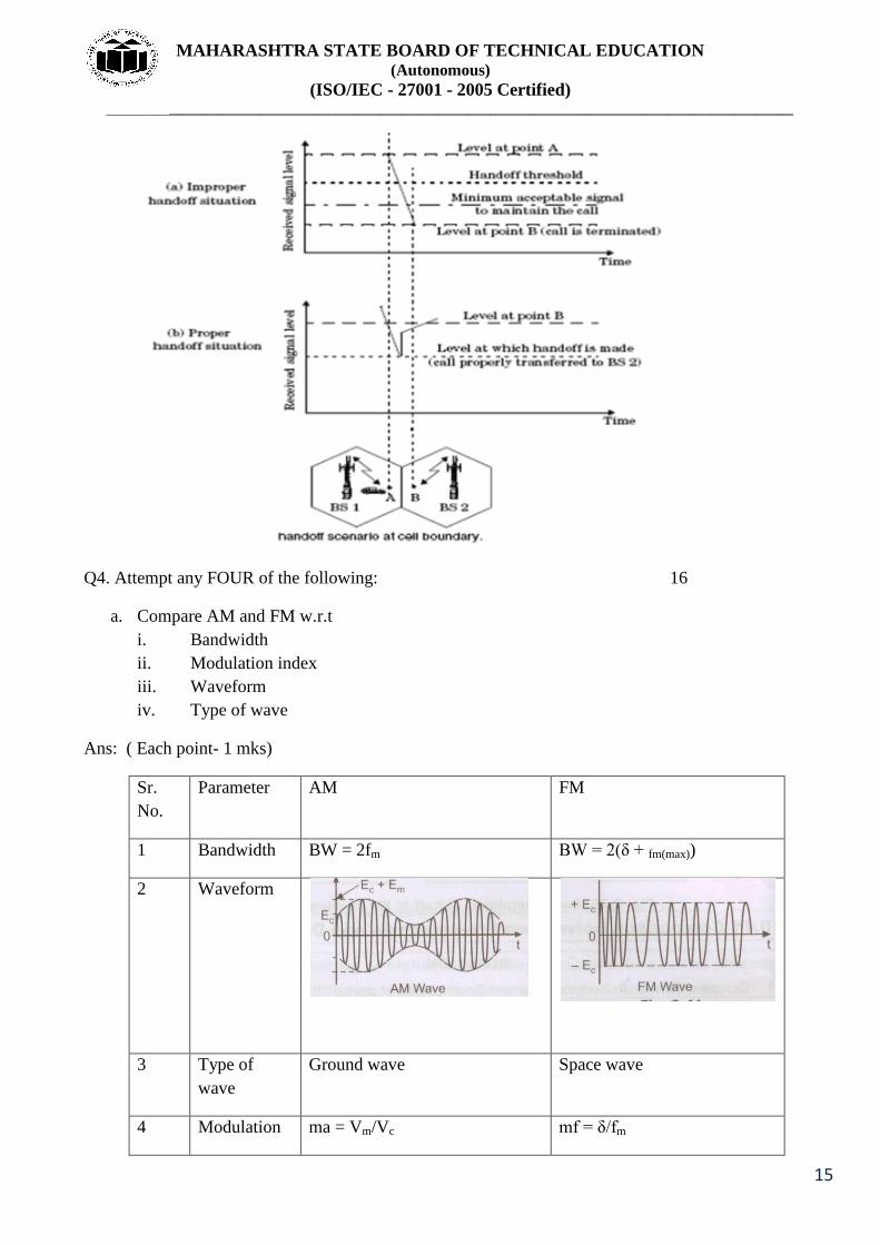
f. Define hand-off in mobile communication. Describe hand-off procedure with neat diagram
ANS:( Definition-1 mks, procedure- 1mks, relevant diagram- 2 mks)
Handoff: Cellular system has the ability to transfer calls thar are already in progress from one cell-
site controller to another as the mobile unit moves from cell to cell within the cellular network.The
transfer of a mobile unit from one base stations control to another base stations control is called a
handoff.
Steps involved in handoff process are:
1)
2) Resource reservation
3) Execution
4) Completion
Page 15
MAHARASHTRA STATE BOARD OF TECHNICAL EDUCATION (Autonomous)
(ISO/IEC - 27001 - 2005 Certified) _____________________________________________________________________________________________
15
Q4. Attempt any FOUR of the following: 16
a. Compare AM and FM w.r.t
i. Bandwidth
ii. Modulation index
iii. Waveform
iv. Type of wave
Ans: ( Each point- 1 mks)
Sr.
No.
Parameter AM FM
1 Bandwidth BW = 2fm BW = 2(δ + fm(max))
2 Waveform
3 Type of
wave
Ground wave Space wave
4 Modulation ma = Vm/Vc mf = δ/fm
Page 16
MAHARASHTRA STATE BOARD OF TECHNICAL EDUCATION (Autonomous)
(ISO/IEC - 27001 - 2005 Certified) _____________________________________________________________________________________________
16
index
b. Draw the block diagram of delta modulation. Explain working of each block.
ANS: ( Block diagram- 2 mks, working – 2 mks)
Working:
1. Sample and Hold circuit:
The input analog is sampled and converted to a PAM signal.
2. DAC:
The output of DAC is a voltage equal to the regenerated magnitude of the previous sample , which
was stored
in the up-down counter as a binary number.
3. Up-Down counter:
The up-down counter is incremented or decremented depending on whether the previous sample is
larger
smaller than the current sample. The up-down counter is clocked at a rate to the sample rate.
Therefore up-down
counter is updated after each comparison.
c. State any four frequency bands used in satellite communication along with its uplink and
downlink frequencies.
Ans:
Frequency bands used in satellite communication. ( any 4 bands- 4 mks)
Band Frequency
L 1.53 – 2.7 GHz
Page 17
MAHARASHTRA STATE BOARD OF TECHNICAL EDUCATION (Autonomous)
(ISO/IEC - 27001 - 2005 Certified) _____________________________________________________________________________________________
17
S 2.5 – 2.7 GHz
C 3.4 – 6.4 GHz
X 7.2 – 8.4 GHz
Ku 10.95 – 14.5 GHz
Ka 17.7 – 31 GHz
Q 36 – 46 GHz
V 46 – 56 GHz
W 56 – 100 GHz
d. State any four advantages of optical fiber communication over other communication system.
ANS: ( Any 4 points- 4 mks)
Advantages of optical fiber communication over other communication system:
1)
2)
3)
4)
5)
6)
7)
8)
9)
10)
e. Compare between LAN,MAN and WAN( any four points)
Ans:- ( each point- 1 mks)
Page 18
MAHARASHTRA STATE BOARD OF TECHNICAL EDUCATION (Autonomous)
(ISO/IEC - 27001 - 2005 Certified) _____________________________________________________________________________________________
18
f. Describe call routing procedure of landline to mobile phone with neat diagram.
Ans:- ( Proper relevant explanation- 4 mks)
When we turn on a cellular phone and it is yet to be engaged in a call, it will first scan the
group of forward channel in order to identify the one having strongest signal and then
monitors that control channel until the signal drops below a usual level.
Then it again searches all the control channel so as to find the strongest base station signal.
When the telephone call is placed to a mobile user, the MTSO or MSC will sent the request
to all the base stations in the system.
The subscribers telephone number called as mobile identification number (min) is then
broadcast as a paging message over all the forward control channels (FCCs) in the system.
The desired mobile receive the paging message sent by the base station and respond by
identifying itself over the reverse control channel (RCC)
The base station relays the acknowledgement sent by the mobile and inform the MTSO
about the handshake.
MTSO tells the base station to move the call to a free voice channel.
Once the call is in process, the MTSO will adjust the transmitted power of the mobile and changes
the channel of mobile unit and base station and so as to maintain call quality even
Q5. Attempt any FOUR of the following (16)
a. Draw block diagram of PCM generation and state function of each block
Ans : ( Block diagram- 2 mks, explanation- 2 mks)
Page 19
MAHARASHTRA STATE BOARD OF TECHNICAL EDUCATION (Autonomous)
(ISO/IEC - 27001 - 2005 Certified) _____________________________________________________________________________________________
19
Working principle of PCM:- The analog signal x (t) is passed through a band limiting low pass filter, which has a cut-off
frequency fc =W Hz. This will ensure that x (t) will not have any frequency component higher than
“W”. This will eliminate the possibility of aliasing.
The band limited analog signal is then applied to a sample and hold the circuit where it is sampled
at adequately high sampling rate. Output of sample and hold block is a flat topped PAM signal.
These samples are then subjected to the operation called “Quantization” in the “Quantizer”. The
quantization is used to reduce the effect of noise. The combined effect of sampling and quantization
produces the quantized PAM at the quantizer output.
The quantized PAM pulses are applied to an encoder which is basically an A to D converter. Each
quantized level is converted into an N bit digital word by the A to D converter. The value of N can
be 8,16,32,64 etc. The encoder output is converted into a stream of pulses by the parallel to serial
converter block. Thus at the PCM transmitter output we get a train of digital pulses.
b. Draw the block diagram of ADM transmitter. Explain how slope overload error is reduced
in ADM.
ANS: ( Block diagram- 2 mks, explanation- 2 mks)
EXPLANATION- In response to the kth pulse the processor generates a step which is equal in
magnitude to the step generated in response to previous i.e(k-1)th clock pulse. If c(t) >c‟(t) then
processor will increase the step size by „ ‟.If c(t)<c‟(t) then processor will decrease the step size by
„ ‟.The comparator compares the analog input c(t) and approximated signal c‟(t) generated by the
digital to analog converter. The sample and hold circuit holds the output of comparator which is
ADM signal.
Page 20
MAHARASHTRA STATE BOARD OF TECHNICAL EDUCATION (Autonomous)
(ISO/IEC - 27001 - 2005 Certified) _____________________________________________________________________________________________
20
c. Draw the block diagram of an earth station.
ANS: ( Proper relevant diagram- 4 mks)
d. Draw block diagram of modern and explain its working.
ANS: ( Block diagram- 2 mks, explanation- 2 mks)
Working:
A satellite modem is not the only device needed to establish a communication channel. Other
equipment that are essential for creating a satellite link include satellite antennas and frequency
converters. Data to be transmitted are transferred to a modem from Data terminal equipment (e.g. a
computer). The modem usually has Intermediate frequency (IF) output (that is, 50-200 MHz),
however, sometimes the signal is modulated directly to L-band. In most cases frequency has to be
converted using an upconverter before amplification and transmission.
A modulated signal is a sequence of symbols, pieces of data represented by a corresponding signal
state, e.g. a bit or a few bits, depending upon the modulation scheme being used. Recovering a
symbol clock (making a local symbol clock generator synchronous with the remote one) is one of
the most important tasks of a demodulator.
Similarly, a signal received from a satellite is firstly downconverted (this is done by a Low-noise
block converter - LNB), then demodulated by a modem, and at last handled by data terminal
equipment. The LNB is usually powered by the modem through the signal cable with 13 or 18 V
DC.
Page 21
MAHARASHTRA STATE BOARD OF TECHNICAL EDUCATION (Autonomous)
(ISO/IEC - 27001 - 2005 Certified) _____________________________________________________________________________________________
21
e. Give operation of hubs and routers in networking.
ANS: ( Each two mks)
Hub: - A Hub is a connecting device. It is actually a multiport repeater. It is
normally used to create connections between terminals in a physical star
topology.
Router: - A Router operates at the physical, data link and network layer of OSI
model. A router is useful for interconnecting two or more networks. These
networks can be heterogeneous. Which means that they can differ in their
physical characteristics such as frame size, transmission rates, topologies,
addressing etc.
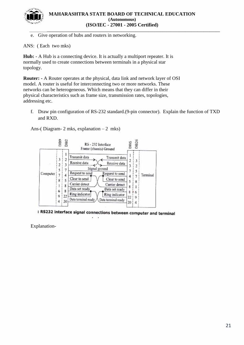
f. Draw pin configuration of RS-232 standard.(9-pin connector). Explain the function of TXD
and RXD.
Ans-( Diagram- 2 mks, explanation – 2 mks)
Explanation-
Page 22
MAHARASHTRA STATE BOARD OF TECHNICAL EDUCATION (Autonomous)
(ISO/IEC - 27001 - 2005 Certified) _____________________________________________________________________________________________
22
Q6. Attempt any FOUR of the following (16)
a. Compare ASK, FSK, PSK, w.r.t
i. Waveform
ii. Variable characteristic
iii. Bit rate
iv. Noise immunity
Ans:-( Each correct point – 1mks)
Parameter ASK FSK PSK
Variable Amplitude Frequency Phase
Page 23
MAHARASHTRA STATE BOARD OF TECHNICAL EDUCATION (Autonomous)
(ISO/IEC - 27001 - 2005 Certified) _____________________________________________________________________________________________
23
characteristi
c
Bit rate
Suitable upto 100 bit /sec Suitable upto 1200 bits
/sec
Suitable upto 1800
bits/sec
Noise
immunity
Low HIGH HIGH
Waveform
b. Describe light propagation in optical fiber with neat diagram. Define acceptance angle
and numerical aperture.
ANS: Propagation of light- Light travels at the speed of 3 * 108 m/sec in free space. If
material denser than free space, speed of the light gets reduced. This reduction in speed as light
passes from free space into the denser medium results in reflection( bending of light). ( 1 mks)
Page 24
MAHARASHTRA STATE BOARD OF TECHNICAL EDUCATION (Autonomous)
(ISO/IEC - 27001 - 2005 Certified) _____________________________________________________________________________________________
24
( each definition 1 ½ mks)
c. State different modes of propagation in an optical fiber. Describe them with neat
diagram.
ANS: ( Different modes – 1 mks, description 1 mks, diagram- 2 mks)
Classification of fibers is as follows;
1 .Step index fibers
i. Single mode
ii. Multimode
2. Graded index
i. Multimode
Single mode- In optical fiber technology, single mode fiber is optical fiber that
is designed for the transmission of a single ray or mode of light as a carrier and
is used for long-distance signal transmission. For short distances, multimode
fiber is used.
Multi mode- In optical fiber technology, multimode fiber is optical fiber that is
designed to carry multiple light rays or modes concurrently, each at a slightly
different reflection angle within the optical fiber core. Multimode fiber
transmission is used for relatively short distances because the modes tend to
disperse over longer lengths (this is called modal dispersion) . For longer
distances, single mode fiber (sometimes called monomode) fiber is used.
Multi mode graded index-In fiber optics, a graded-index or gradient-index
fiber is an optical fiber whose core has a refractive index that decreases with
Page 25
MAHARASHTRA STATE BOARD OF TECHNICAL EDUCATION (Autonomous)
(ISO/IEC - 27001 - 2005 Certified) _____________________________________________________________________________________________
25
increasing radial distance from the optical axis of the fiber.
d. Explain synchronous and asynchronous mode of data transmission.
ANS: ( Diagram – 1mks each, explanation- 1 mks each)
There are two types of serial data transmission.
i) Synchronous data transmission:-
control of a common master clock. Here the bits which are being
transmitted are synchronized to a reference clock.
are transmitted as a block in y same
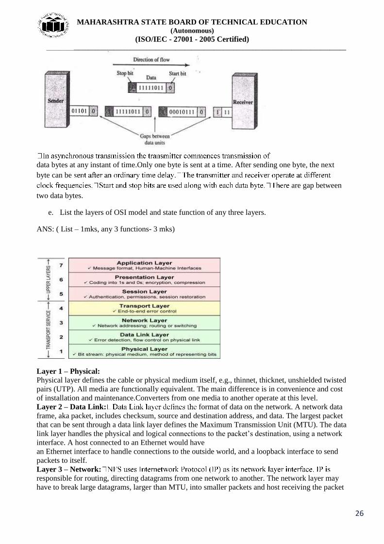
ii) Asynchronous data transmission :-
Page 26
MAHARASHTRA STATE BOARD OF TECHNICAL EDUCATION (Autonomous)
(ISO/IEC - 27001 - 2005 Certified) _____________________________________________________________________________________________
26
data bytes at any instant of time.Only one byte is sent at a time. After sending one byte, the next
byte can be
are gap between
two data bytes.
e. List the layers of OSI model and state function of any three layers.
ANS: ( List – 1mks, any 3 functions- 3 mks)
Layer 1 – Physical:
Physical layer defines the cable or physical medium itself, e.g., thinnet, thicknet, unshielded twisted
pairs (UTP). All media are functionally equivalent. The main difference is in convenience and cost
of installation and maintenance.Converters from one media to another operate at this level.
Layer 2 – Data Link: format of data on the network. A network data
frame, aka packet, includes checksum, source and destination address, and data. The largest packet
that can be sent through a data link layer defines the Maximum Transmission Unit (MTU). The data
link layer handles the physical and logical connections to the packet‟s destination, using a network
interface. A host connected to an Ethernet would have
an Ethernet interface to handle connections to the outside world, and a loopback interface to send
packets to itself.
Layer 3 – Network:
responsible for routing, directing datagrams from one network to another. The network layer may
have to break large datagrams, larger than MTU, into smaller packets and host receiving the packet
Page 27
MAHARASHTRA STATE BOARD OF TECHNICAL EDUCATION (Autonomous)
(ISO/IEC - 27001 - 2005 Certified) _____________________________________________________________________________________________
27
will have to reassemble the fragmented datagram. The Internetwork Protocol identifies each host
with a 32-bit IP address. IP addresses are written as four dotseparated
decimal numbers between 0 and 255, e.g., 129.79.16.40.
Layer 4 – Transport: -buffer into network-buffer sized datagrams
and enforces desired transmission control. Two transport protocols, Transmission Control Protocol
(TCP) and User Datagram Protocol (UDP), sits at the transport layer. Reliability and speed are the
primary difference between these two protocols. TCP
establishes connections between two hosts on the network through „sockets‟ which are determined
by the IP address and port number.
Layer 5 – Session:The session protocol defines the format of the data sent over the connections.
The NFS uses the Remote Procedure Call (RPC) for its session protocol. RPC may be built on
either TCP or UDP. Login sessions use TCP whereas NFS and broadcast use UDP.
Layer 6 – Presentation: External Data Representation (XDR) sits at the presentation level. It
converts local representation of data to its canonical form and vice versa. The canonical uses a
standard byte ordering and structure packing convention, independent of the host.
Layer 7 – Application- Provides network services to the end-users. Mail, ftp, telnet, DNS, NIS,
NFS are examples of network applications.
f. Draw block diagram of transponder in satellite and explain its working.
Ans:( Diagram – 2 mks, explanation – 2 mks)
EXPLANATION-
A typical satellite transponder consists of an input band limiting device (BPF), an
input low-noise amplifier (LNA), a frequency translator, a low-level power
amplifier, and an output BPF.
The input BPF limits the total noise applied to the input of the LNA. The output of the
LNA is fed to a frequency translator (a shift oscillator and a BPF), which converts the high-band
uplink frequency to the low0band downlink frequency.
The low-level power amplifier, which is commonly a travelling wave tube,
amplifies the RF signal for transmission through downlink to earth station
receivers. Each RF satellite channel requires separate transponders
Page 28
MAHARASHTRA STATE BOARD OF TECHNICAL EDUCATION (Autonomous)
(ISO/IEC - 27001 - 2005 Certified) _____________________________________________________________________________________________
28
_____________________