69
Maintenance and Repair Manual F2C to F1200CS+ F105CTWS+ to F1200CWSD+ Refrigerant Dryers Air- and Water-Cooled DL101BA-01/2010
Maintenance and Repair Manual
F2C to F1200CS+F105CTWS+ to F1200CWSD+
Refrigerant DryersAir- and Water-Cooled
DL1
01B
A-0
1/20
10
SM 1517
CompAir Contents
Contents1 Safety Regulations. . . . . . . . . . . . . . . . . . . . . . . . . . . . . . . . . . . . . . . . . . . . . . . . . . . . . . . . . . . . . . . . . . . . 51.1 Important safety notes - PLEASE READ . . . . . . . . . . . . . . . . . . . . . . . . . . . . . . . . . . . . . . . . . . . . . . . . . . 51.2 Transportation. . . . . . . . . . . . . . . . . . . . . . . . . . . . . . . . . . . . . . . . . . . . . . . . . . . . . . . . . . . . . . . . . . . . . . . 51.3 Positioning . . . . . . . . . . . . . . . . . . . . . . . . . . . . . . . . . . . . . . . . . . . . . . . . . . . . . . . . . . . . . . . . . . . . . . . . . 51.4 Installation. . . . . . . . . . . . . . . . . . . . . . . . . . . . . . . . . . . . . . . . . . . . . . . . . . . . . . . . . . . . . . . . . . . . . . . . . . 51.5 Before Operating. . . . . . . . . . . . . . . . . . . . . . . . . . . . . . . . . . . . . . . . . . . . . . . . . . . . . . . . . . . . . . . . . . . . . 51.6 Maintenance by an Engineer . . . . . . . . . . . . . . . . . . . . . . . . . . . . . . . . . . . . . . . . . . . . . . . . . . . . . . . . . . . 51.7 Maintenance by the user. . . . . . . . . . . . . . . . . . . . . . . . . . . . . . . . . . . . . . . . . . . . . . . . . . . . . . . . . . . . . . . 61.8 Environmental Protection . . . . . . . . . . . . . . . . . . . . . . . . . . . . . . . . . . . . . . . . . . . . . . . . . . . . . . . . . . . . . . 62 Technical Information . . . . . . . . . . . . . . . . . . . . . . . . . . . . . . . . . . . . . . . . . . . . . . . . . . . . . . . . . . . . . . . . . 72.1 Single-Phase Dryers . . . . . . . . . . . . . . . . . . . . . . . . . . . . . . . . . . . . . . . . . . . . . . . . . . . . . . . . . . . . . . . . . . 72.2 Three-Phase Dryers . . . . . . . . . . . . . . . . . . . . . . . . . . . . . . . . . . . . . . . . . . . . . . . . . . . . . . . . . . . . . . . . . . 72.3 For All Models . . . . . . . . . . . . . . . . . . . . . . . . . . . . . . . . . . . . . . . . . . . . . . . . . . . . . . . . . . . . . . . . . . . . . . . 82.4 Model Names . . . . . . . . . . . . . . . . . . . . . . . . . . . . . . . . . . . . . . . . . . . . . . . . . . . . . . . . . . . . . . . . . . . . . . . 83 General Description. . . . . . . . . . . . . . . . . . . . . . . . . . . . . . . . . . . . . . . . . . . . . . . . . . . . . . . . . . . . . . . . . . . 93.1 General Arrangement - Typical Small Machines . . . . . . . . . . . . . . . . . . . . . . . . . . . . . . . . . . . . . . . . . . . . 93.2 General Arrangement - Typical Medium Machines. . . . . . . . . . . . . . . . . . . . . . . . . . . . . . . . . . . . . . . . . . 103.3 General Arrangement - Typical Large Machines . . . . . . . . . . . . . . . . . . . . . . . . . . . . . . . . . . . . . . . . . . . 113.4 Purpose Of This Dryer . . . . . . . . . . . . . . . . . . . . . . . . . . . . . . . . . . . . . . . . . . . . . . . . . . . . . . . . . . . . . . . 123.5 Control Panel - F2C/F2C+ to F16C/F16C+. . . . . . . . . . . . . . . . . . . . . . . . . . . . . . . . . . . . . . . . . . . . . . . . 123.6 Control Panel - F22C/F22C+ to F84C/F84C+. . . . . . . . . . . . . . . . . . . . . . . . . . . . . . . . . . . . . . . . . . . . . . 123.7 Control Panel - F105C+ to F1200C+ . . . . . . . . . . . . . . . . . . . . . . . . . . . . . . . . . . . . . . . . . . . . . . . . . . . . 123.8 Digital Temperature Controller . . . . . . . . . . . . . . . . . . . . . . . . . . . . . . . . . . . . . . . . . . . . . . . . . . . . . . . . . 123.9 Digital Temperature Controller (earlier version) . . . . . . . . . . . . . . . . . . . . . . . . . . . . . . . . . . . . . . . . . . . . 133.10 Digital Temperature Controller (later version). . . . . . . . . . . . . . . . . . . . . . . . . . . . . . . . . . . . . . . . . . . . . . 143.11 Energy Saving Devices (ESD) . . . . . . . . . . . . . . . . . . . . . . . . . . . . . . . . . . . . . . . . . . . . . . . . . . . . . . . . . 153.12 Starting and Stopping . . . . . . . . . . . . . . . . . . . . . . . . . . . . . . . . . . . . . . . . . . . . . . . . . . . . . . . . . . . . . . . . 153.13 During operation . . . . . . . . . . . . . . . . . . . . . . . . . . . . . . . . . . . . . . . . . . . . . . . . . . . . . . . . . . . . . . . . . . . . 163.14 Refrigerant Circuit: Description . . . . . . . . . . . . . . . . . . . . . . . . . . . . . . . . . . . . . . . . . . . . . . . . . . . . . . . . 163.15 Refrigerant Circuit: Operation . . . . . . . . . . . . . . . . . . . . . . . . . . . . . . . . . . . . . . . . . . . . . . . . . . . . . . . . . . 173.16 Compressed Air Circuit . . . . . . . . . . . . . . . . . . . . . . . . . . . . . . . . . . . . . . . . . . . . . . . . . . . . . . . . . . . . . . . 173.17 Refrigerant Compressor . . . . . . . . . . . . . . . . . . . . . . . . . . . . . . . . . . . . . . . . . . . . . . . . . . . . . . . . . . . . . . 173.18 Condenser . . . . . . . . . . . . . . . . . . . . . . . . . . . . . . . . . . . . . . . . . . . . . . . . . . . . . . . . . . . . . . . . . . . . . . . . 173.19 Refrigerant Circuit Protection . . . . . . . . . . . . . . . . . . . . . . . . . . . . . . . . . . . . . . . . . . . . . . . . . . . . . . . . . . 173.20 Filter-dryer. . . . . . . . . . . . . . . . . . . . . . . . . . . . . . . . . . . . . . . . . . . . . . . . . . . . . . . . . . . . . . . . . . . . . . . . . 173.21 Crankcase Heater . . . . . . . . . . . . . . . . . . . . . . . . . . . . . . . . . . . . . . . . . . . . . . . . . . . . . . . . . . . . . . . . . . . 173.22 Refrigerant Circuit Regulation - F2C To F16C . . . . . . . . . . . . . . . . . . . . . . . . . . . . . . . . . . . . . . . . . . . . . 173.23 Refrigerant Circuit Regulation - F22C To F1200C +. . . . . . . . . . . . . . . . . . . . . . . . . . . . . . . . . . . . . . . . . 183.24 Condensate Drain-trap Assembly . . . . . . . . . . . . . . . . . . . . . . . . . . . . . . . . . . . . . . . . . . . . . . . . . . . . . . . 183.25 Heat Exchanger Modular Design . . . . . . . . . . . . . . . . . . . . . . . . . . . . . . . . . . . . . . . . . . . . . . . . . . . . . . . 183.26 Accessories. . . . . . . . . . . . . . . . . . . . . . . . . . . . . . . . . . . . . . . . . . . . . . . . . . . . . . . . . . . . . . . . . . . . . . . . 184 Initial Inspection. . . . . . . . . . . . . . . . . . . . . . . . . . . . . . . . . . . . . . . . . . . . . . . . . . . . . . . . . . . . . . . . . . . . . 194.1 Initial Checks. . . . . . . . . . . . . . . . . . . . . . . . . . . . . . . . . . . . . . . . . . . . . . . . . . . . . . . . . . . . . . . . . . . . . . . 194.2 Running Test. . . . . . . . . . . . . . . . . . . . . . . . . . . . . . . . . . . . . . . . . . . . . . . . . . . . . . . . . . . . . . . . . . . . . . . 194.3 Final Checks . . . . . . . . . . . . . . . . . . . . . . . . . . . . . . . . . . . . . . . . . . . . . . . . . . . . . . . . . . . . . . . . . . . . . . . 195 Typical Faults . . . . . . . . . . . . . . . . . . . . . . . . . . . . . . . . . . . . . . . . . . . . . . . . . . . . . . . . . . . . . . . . . . . . . . . 205.1 Electrical Circuit . . . . . . . . . . . . . . . . . . . . . . . . . . . . . . . . . . . . . . . . . . . . . . . . . . . . . . . . . . . . . . . . . . . . 205.2 Compressed Air Circuit . . . . . . . . . . . . . . . . . . . . . . . . . . . . . . . . . . . . . . . . . . . . . . . . . . . . . . . . . . . . . . . 205.3 Refrigerant circuits . . . . . . . . . . . . . . . . . . . . . . . . . . . . . . . . . . . . . . . . . . . . . . . . . . . . . . . . . . . . . . . . . . 206 Fault Finding . . . . . . . . . . . . . . . . . . . . . . . . . . . . . . . . . . . . . . . . . . . . . . . . . . . . . . . . . . . . . . . . . . . . . . . 21
DL101BA 3
Contents CompAir
7 Maintenance . . . . . . . . . . . . . . . . . . . . . . . . . . . . . . . . . . . . . . . . . . . . . . . . . . . . . . . . . . . . . . . . . . . . . . . . 237.1 Quarterly Maintenance: normally undertaken by the enduser . . . . . . . . . . . . . . . . . . . . . . . . . . . . . . . . . 237.2 Annual Maintenance: to be carried out by a qualified and certified refrigeration engineer . . . . . . . . . . . . 237.3 To Remove and Refit the Refrigerant Compressor. . . . . . . . . . . . . . . . . . . . . . . . . . . . . . . . . . . . . . . . . . 247.4 Refrigerant Filling Procedure . . . . . . . . . . . . . . . . . . . . . . . . . . . . . . . . . . . . . . . . . . . . . . . . . . . . . . . . . . 277.5 Bekomat Drain . . . . . . . . . . . . . . . . . . . . . . . . . . . . . . . . . . . . . . . . . . . . . . . . . . . . . . . . . . . . . . . . . . . . . 308 Maintenance Parts Kits . . . . . . . . . . . . . . . . . . . . . . . . . . . . . . . . . . . . . . . . . . . . . . . . . . . . . . . . . . . . . . . 318.1 One-Year Parts Kits . . . . . . . . . . . . . . . . . . . . . . . . . . . . . . . . . . . . . . . . . . . . . . . . . . . . . . . . . . . . . . . . . 318.2 Three-Year Parts Kits (Refrigeration) . . . . . . . . . . . . . . . . . . . . . . . . . . . . . . . . . . . . . . . . . . . . . . . . . . . 328.3 Three-year Parts Kits for Fan . . . . . . . . . . . . . . . . . . . . . . . . . . . . . . . . . . . . . . . . . . . . . . . . . . . . . . . . . . 338.4 Five-year Parts Kits. . . . . . . . . . . . . . . . . . . . . . . . . . . . . . . . . . . . . . . . . . . . . . . . . . . . . . . . . . . . . . . . . . 338.5 Ten-year Parts Kits . . . . . . . . . . . . . . . . . . . . . . . . . . . . . . . . . . . . . . . . . . . . . . . . . . . . . . . . . . . . . . . . . . 349 Installation and Electrical Diagrams . . . . . . . . . . . . . . . . . . . . . . . . . . . . . . . . . . . . . . . . . . . . . . . . . . . . 359.1 Installation Diagram - F2C/F2C+ - F7C/F7C+ . . . . . . . . . . . . . . . . . . . . . . . . . . . . . . . . . . . . . . . . . . . . . 359.2 Installation Diagram - F11C/F11C+, F16C/F16C+, F22C/F22C+, F26C/F26C+ . . . . . . . . . . . . . . . . . . . 369.3 Installation Diagram - F36C/F36C+, F54C/F54C+ . . . . . . . . . . . . . . . . . . . . . . . . . . . . . . . . . . . . . . . . . . 379.4 Installation Diagram - F72C, F72C+ . . . . . . . . . . . . . . . . . . . . . . . . . . . . . . . . . . . . . . . . . . . . . . . . . . . . . 389.5 Installation Diagram - F84C, F84C+ . . . . . . . . . . . . . . . . . . . . . . . . . . . . . . . . . . . . . . . . . . . . . . . . . . . . . 399.6 Installation Diagram - F105C, F105C+, F133C, F133C+ . . . . . . . . . . . . . . . . . . . . . . . . . . . . . . . . . . . . . 409.7 Installation Diagram - F156C+, F183C+, F210C+ . . . . . . . . . . . . . . . . . . . . . . . . . . . . . . . . . . . . . . . . . . 419.8 Installation Diagram - F240C+, F384C+ . . . . . . . . . . . . . . . . . . . . . . . . . . . . . . . . . . . . . . . . . . . . . . . . . . 429.9 Installation Diagram - F444C+, F522C+ . . . . . . . . . . . . . . . . . . . . . . . . . . . . . . . . . . . . . . . . . . . . . . . . . . 439.10 Installation Diagram - F678C+ . . . . . . . . . . . . . . . . . . . . . . . . . . . . . . . . . . . . . . . . . . . . . . . . . . . . . . . . . 449.11 Installation Diagram - F780C+ . . . . . . . . . . . . . . . . . . . . . . . . . . . . . . . . . . . . . . . . . . . . . . . . . . . . . . . . . 459.12 Installation Diagram - F930C+, F1050C+ . . . . . . . . . . . . . . . . . . . . . . . . . . . . . . . . . . . . . . . . . . . . . . . . . 469.13 Installation Diagram - F1200C+ . . . . . . . . . . . . . . . . . . . . . . . . . . . . . . . . . . . . . . . . . . . . . . . . . . . . . . . . 479.14 Electrical Diagram - F2C/F2C+ to F7C/F7C+ (230/1/50 and 60 Hz) . . . . . . . . . . . . . . . . . . . . . . . . . . . . 489.15 Electrical Diagram - F2C/F2C+ to F7C/F7C+ (230/1/50 and 60 Hz) with optional ESD 1 . . . . . . . . . . . . 499.16 Electrical Diagram - F11C/F11C+ to F45C/F45C+ (230/1/50 and 60Hz) . . . . . . . . . . . . . . . . . . . . . . . . . 509.17 Electrical Diagram - F11C/F11C+ to F45C/F45C+ (230/1/50 and 60Hz) with optional ESD1. . . . . . . . . 519.18 Electrical Diagram - F54C/F54C+ to F105C+ (230/1/50 and 60Hz) . . . . . . . . . . . . . . . . . . . . . . . . . . . . . 529.19 Electrical Diagram - F54C/F54C+ to F105C+ (230/1/50 and 60Hz) with optional ESD1 . . . . . . . . . . . . . 539.20 Electrical Diagram - F133C/F133C+ (230/1/50 and 60Hz) . . . . . . . . . . . . . . . . . . . . . . . . . . . . . . . . . . . . 549.21 Electrical Diagram - F133C/F133C+ (230/1/50 and 60Hz) with optional ESD1 . . . . . . . . . . . . . . . . . . . . 559.22 Control Circuit - F72CT+, F84CT+, F105CT+ / ESD2 (400-440/3/50 and 60Hz) . . . . . . . . . . . . . . . . . . 569.23 Power Circuit - F72CT+, F84CT+, F105CT+ / ESD2 (400-440/3/50 and 60Hz). . . . . . . . . . . . . . . . . . . 579.24 Control Circuit - F72CT+, F84CT+, F105CT+ - (400-440/3/50 & 60Hz) with optional ESD3. . . . . . . . . . 589.25 Power Circuit - F72CT+, F84CT+, F105CT+ - (400-440/3/50 & 60Hz) with optional ESD3 . . . . . . . . . . 599.26 Control Circuit - F133CT+ to F930C+ / ESD2 (400-440/3/50 and 60Hz) . . . . . . . . . . . . . . . . . . . . . . . . . 609.27 Power Circuit - F133CT+ to F930C+ / ESD2 (400-440/3/50 and 60Hz) . . . . . . . . . . . . . . . . . . . . . . . . . . 619.28 Control Circuit - F133CT+ to F930C+ (400-440/3/50 and 60Hz) with optional ESD3. . . . . . . . . . . . . . . . 629.29 Power Circuit - F133CT+ to F930C+ (400-440/3/50 and 60Hz) with optional ESD3 . . . . . . . . . . . . . . . . 639.30 Control Circuit - F1050C+ to F1200C+ /ESD2 (400-440/3/50 and 60Hz) . . . . . . . . . . . . . . . . . . . . . . . . 649.31 Power Circuit - F1050C+ to F1200C+ /ESD2 (400-440/3/50 and 60Hz) . . . . . . . . . . . . . . . . . . . . . . . . . 659.32 Control Circuit - F1050C+ to F1200C+ (400-440/3/50 and 60Hz) with optional ESD3. . . . . . . . . . . . . . . 669.33 Power Circuit - F1050C+ to F1200C+ (400-440/3/50 and 60Hz) with optional ESD3 . . . . . . . . . . . . . . . 67
4 DL101BA
CompAir Safety Regulations 1
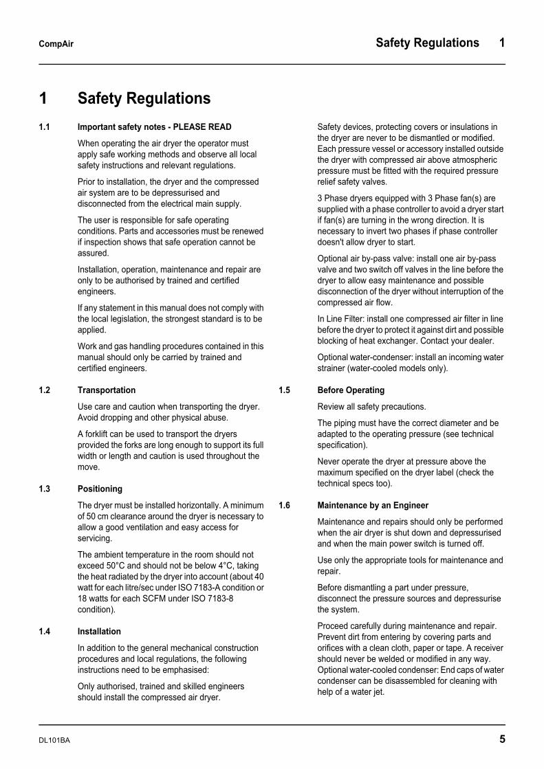
1 Safety Regulations1.1 Important safety notes - PLEASE READ
When operating the air dryer the operator must apply safe working methods and observe all local safety instructions and relevant regulations.
Prior to installation, the dryer and the compressed air system are to be depressurised and disconnected from the electrical main supply.
The user is responsible for safe operating conditions. Parts and accessories must be renewed if inspection shows that safe operation cannot be assured.
Installation, operation, maintenance and repair are only to be authorised by trained and certified engineers.
If any statement in this manual does not comply with the local legislation, the strongest standard is to be applied.
Work and gas handling procedures contained in this manual should only be carried by trained and certified engineers.
1.2 Transportation
Use care and caution when transporting the dryer. Avoid dropping and other physical abuse.
A forklift can be used to transport the dryers provided the forks are long enough to support its full width or length and caution is used throughout the move.
1.3 Positioning
The dryer must be installed horizontally. A minimum of 50 cm clearance around the dryer is necessary to allow a good ventilation and easy access for servicing.
The ambient temperature in the room should not exceed 50°C and should not be below 4°C, taking the heat radiated by the dryer into account (about 40 watt for each litre/sec under ISO 7183-A condition or 18 watts for each SCFM under ISO 7183-8 condition).
1.4 Installation
In addition to the general mechanical construction procedures and local regulations, the following instructions need to be emphasised:
Only authorised, trained and skilled engineers should install the compressed air dryer.
Safety devices, protecting covers or insulations in the dryer are never to be dismantled or modified. Each pressure vessel or accessory installed outside the dryer with compressed air above atmospheric pressure must be fitted with the required pressure relief safety valves.
3 Phase dryers equipped with 3 Phase fan(s) are supplied with a phase controller to avoid a dryer start if fan(s) are turning in the wrong direction. It is necessary to invert two phases if phase controller doesn't allow dryer to start.
Optional air by-pass valve: install one air by-pass valve and two switch off valves in the line before the dryer to allow easy maintenance and possible disconnection of the dryer without interruption of the compressed air flow.
In Line Filter: install one compressed air filter in line before the dryer to protect it against dirt and possible blocking of heat exchanger. Contact your dealer.
Optional water-condenser: install an incoming water strainer (water-cooled models only).
1.5 Before Operating
Review all safety precautions.
The piping must have the correct diameter and be adapted to the operating pressure (see technical specification).
Never operate the dryer at pressure above the maximum specified on the dryer label (check the technical specs too).
1.6 Maintenance by an Engineer
Maintenance and repairs should only be performed when the air dryer is shut down and depressurised and when the main power switch is turned off.
Use only the appropriate tools for maintenance and repair.
Before dismantling a part under pressure, disconnect the pressure sources and depressurise the system.
Proceed carefully during maintenance and repair. Prevent dirt from entering by covering parts and orifices with a clean cloth, paper or tape. A receiver should never be welded or modified in any way. Optional water-cooled condenser: End caps of water condenser can be disassembled for cleaning with help of a water jet.
DL101BA 5
1 Safety Regulations CompAir
Never leave tools, loose parts or cleaning rags in or on the air dryer.
Before returning the dryer into service, check the setting of the control and safety devices as well as the pressure and the temperature of the compressed air circuit.
1.7 Maintenance by the user
Keep the dryer clean.
In case of more than 2.0 kg of refrigerant, the dryer should be regularly checked to be leak free by qualified refrigerant engineer. Refer to section "Environmental protection" of this manual.
Every six month check the correct operation of the condenser drain trap. Renew timer or solenoid valve in case of blocking or malfunction.
Every six month: check and clean the drain strainer or the electronic sensor by releasing the access screw and washing the filter with tap water to remove the trapped dirt from the inside.
Every six months: If a pressure assisted membrane drain valve is used clean or renew the membrane every six months.
For air-cooled dryers: clean the air condenser with a brush or compressed air flushes as soon as it's dirty or blocked: Take care not to bend the copper fins of the radiator.
For water-cooled condenser: use only clean water. Use water counter flow to clean condenser in case of need.
Check the trouble-shooting list in case of maintenance troubles.
Check operating pressures, temperatures and time settings after maintenance. If operating and safety devices function properly, the air dryer may be used.
1.8 Environmental Protection
EU laws protect the environment against refrigerant being released into the atmosphere.
An annual leak test at less than 5.0 grs/year should be performed by a qualified engineer if the refrigerant dryer contains more than 2.0 kg of refrigerant. This control has to be done twice a year if the dryer contains more than 30.0 kg.
Be Aware: EU local governments may place penalties if this requirement is not respected.
Before dryer disposal, the refrigerant must be properly recovered by a qualified engineer.
6 DL101BA

CompAir Technical Information 2
2 Technical Information2.1 Single-Phase Dryers
Notes on the table below :- (i) * Models are 50Hz type with timer drain. (ii) “+” signifies optional Bekomat integrated
2.2 Three-Phase Dryers
Notes on the table below :- (i) “ + ” signifies Bekomat integrated. (ii) “ T ” means this model is available with either single-phase or three-phase electrics. (iii) Bekomat drain is standard in 3-phase dryers, except F72CT and F84CT. (iv) “ * ” figures are for air-cooled models only.
Dryer Model *
Optional Bekomat
integrated (+) *
60 Hz Type with timer
drain
Compressed Air Flow (m3/min)
Pressure Drop (mbar)
In/Out Connection
(BSPP)
A. Refrigerant
Refrigerant Quantity
(kg)
CompressorPower/50Hz
(kw)
Fan Power/50Hz
(kw)
Total Absorbed
Power/50Hz (kw)
Total Absorbed
Power 60Hz (kw)
Maximum Amperage
(Amp)
Fuse Amps (Amp)
IPRatings
WeightWith Box
(kg)
Voltage
50Hz 60Hz
F2C F2C+ F2C60 0.183 10
1/2”
R134a
0.28 0.245
0.005
0.25 0.28 2 2
IP54
30
230/
1/50
Hz
230/
1/60
Hz
F3C F3C+ F3C60 0.264 10 0.28 0.245 0.25 0.28 2 2 30
F5C F5C+ F5C60 0.48 20 0.30 0.245 0.25 0.28 2 2 32
F7C F7C+ F7C60 0.732 30 0.32 0.245 0.25 0.36 2 2 32
F11C F11C+ F11C60 1.14 20
3/4”
0.75 0.275 0.28 0.36 2.5 4 53
F16C F16C+ F16C60 1.62 50 0.75 0.345 0.35 0.40 2.6 4 54
F22C F22C+ F22C60 2.22 60 0.80 0.575 0.58 0.63 4.9 6 56
F26C F26C+ F26C60 2.58 80 0.80 0.635
0.025
0.66 0.79 5.1 6 59
F36C F36C+ F36C60 3.6 1301 1/4”
1.30 0.775 0.80 0.91 6.5 8 86
F45C F45C+ F45C60 4.5 160 1.30 1.075 1.10 1.14 8.9 10 93
F54C F54C+ F54C60 5.4 2251 1/2”
1.30 1.275 1.30 1.48 9.1 10 93
F72C F72C+ F72C60 7.2 260 2.5 1.080.09
1.17 1.56 8.9 10 127
F84C F84C+ F84C60 8.4 330
2”
4 1.28 1.37 1.56 9.1 10 163
F105C F105C+ F105C60 10.5 180 5 1.280.2
1.48 1.65 9.1 10 214
F133C F133C+ F133C60 13.3 250 5 1.75 1.95 2.44 4.6 6 233
ESD1Optional for single-phase dryers
Instead of a color zone thermometer, an Energy Saving Device (which has a digital dew point meter) is used. Energy Saving Device switches off automatically at no load. When the compressed air enters in to the dryer again, the energy saving device switches on the dryer again.
50 Hz Type with timer drain 60 Hz Type
with timer drain
Water Cooled Models Compressed Air Flow (m3/min)
Pressure Drop
(mbar)
In/Out Connection
(BSPP)
A. Refrigerant
RefrigerantQuantity
(kg)
Compressor Power50Hz
(kw) *
Fan Power 50Hz
(kw) *
Total Absorbed
Power 50Hz (kw)
Total Absorbed
Power 60Hz (kw)
Maximum Amperage
(Amp)
Fuse Amps (Amp)
IPRating
Weight With Box
(kg)
Voltage
Dryer Model 50 Hz 60 Hz 50Hz 60Hz
F72CTF72CT+ F72CT60+ — — 7.2 260 1 1/2”
R134a
2.50 0.975 0.145 1.12 1.39 3.2 4
IP54
130
400/
3/50
Hz
440/
3/60
Hz
F84CTF84CT+ 84CT60+ — — 8.4 330
2”
4 1.275 0.145 1.42 1.73 3.8 4 166
F105CT+ F105C60+ F105CTW+ F105CTW60+ 10.5 180 5 1.275 0.180 1.46 1.77 3.8 4 217
F133CT+ F133CT60+ F133CTW+ F133CTW60+ 13.3 250 5 1.750 0.180 1.93 2.44 4.6 6 236
F156C+ F156C60+ F156CW+ F156CW60+ 15.6 320
3”
7 2.290 0.180 2.47 3.20 4.6 6 278
F183C+ F183C60+ F183CW+ F183CW60+ 18.3 380 7 2.440 0.180 2.62 3.29 6 6 280
F210C+ F210C60+ F210CW+ F210CW60+ 21 280 10 2.440 0.180 2.62 3.84 6 6 324
F240C+ F240C60+ F240CW+ F240CW60+ 24 360 10 2.900 0.180 3.08 5.56 7.8 10 433
F285C+ F285C60+ F285CW+ F285CW60+ 28.5 380
R404a
10 4.120 0.180 4.30 6.44 11 12 435
F348C+ F348C60+ F348CW+ F348CW60+ 34.8 380 13.5 4.740 0.280 5.02 6.88 12.5 14 489
F384C+ F384C60+ F384CW+ F384CW60+ 38.4 420 13.5 5.360 0.280 5.64 8.14 13 14 491
F444C+ F444C60+ F444CW+ F444CW60+ 44.4 400
4”
17 5.920 0.280 6.2 1.56 15 16 666
F522C+ F522C60+ F522CW+ F522C60W+ 52.2 380 20 6.700 0.280 6.98 8.54 16 16 703
F678C+ F678C60+ F678CW+ F678CW60+ 67.8 400 24 9.480 0.640 10.12 13.10 24 25 897
F780C+ F780C60+ F780CW+ F780CW60+ 78 420
DN150
27 11.830 0.640 12.47 15.30 25 25 996
F930C+ F930C60+ F930CW+ F930CW60+ 93 400 34 11.830 0.790 12.62 15.30 29 30 1489
F1050C+ F1050C60+ F1050CW+ F1050CW60+ 105 400 37 13.420 0.790 14.21 17.20 32 32 1573
F1200C+ F1200C60+ F1200CW+ F1200CW60+ 120 420 40 15.500 0.790 16.29 19.69 33 40 1770
ESD2Standard for three-phase dryers
Instead of a color zone thermometer, an Energy Saving Device (which has a digital dew point meter) is used. Energy Saving Device switches off automatically at no load. When the compressed air enters in to the dryer again, the energy saving device switches on the dryer again.
ESD3Optional for three-phase dryers PLC display clear text multilingual indication of alarms, maintenance and running hours + Energy-Saving Device automatic switching OFF at no load and ON when warm compressed air is entering.
DL101BA 7
2 Technical Information CompAir
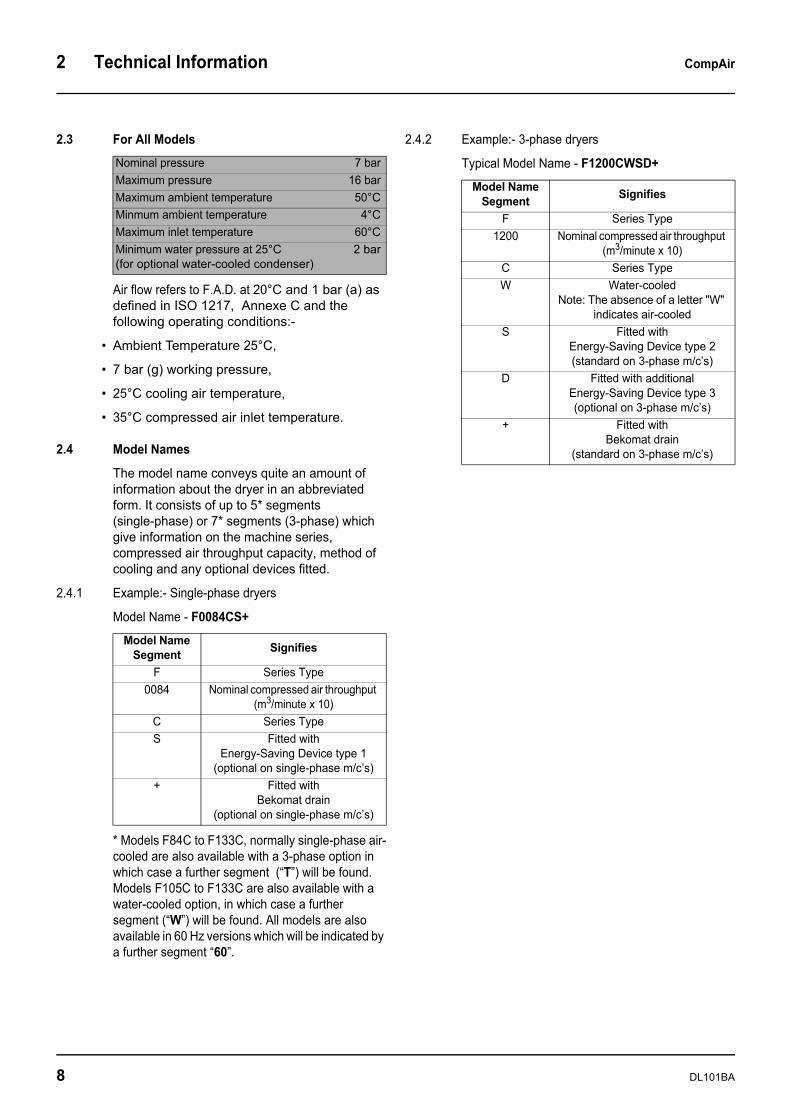
2.3 For All Models
Air flow refers to F.A.D. at 20°C and 1 bar (a) as defined in ISO 1217, Annexe C and the following operating conditions:-
• Ambient Temperature 25°C,
• 7 bar (g) working pressure,
• 25°C cooling air temperature,
• 35°C compressed air inlet temperature.
2.4 Model Names
The model name conveys quite an amount of information about the dryer in an abbreviated form. It consists of up to 5* segments (single-phase) or 7* segments (3-phase) which give information on the machine series, compressed air throughput capacity, method of cooling and any optional devices fitted.
2.4.1 Example:- Single-phase dryers
Model Name - F0084CS+
* Models F84C to F133C, normally single-phase air-cooled are also available with a 3-phase option in which case a further segment (“T”) will be found. Models F105C to F133C are also available with a water-cooled option, in which case a further segment (“W”) will be found. All models are also available in 60 Hz versions which will be indicated by a further segment “60”.
2.4.2 Example:- 3-phase dryers
Typical Model Name - F1200CWSD+Nominal pressure 7 barMaximum pressure 16 barMaximum ambient temperature 50°CMinmum ambient temperature 4°CMaximum inlet temperature 60°CMinimum water pressure at 25°C 2 bar(for optional water-cooled condenser)
Model Name Segment Signifies
F Series Type0084 Nominal compressed air throughput
(m3/minute x 10)C Series TypeS Fitted with
Energy-Saving Device type 1(optional on single-phase m/c’s)
+ Fitted withBekomat drain
(optional on single-phase m/c’s)
Model Name Segment Signifies
F Series Type1200 Nominal compressed air throughput
(m3/minute x 10)C Series TypeW Water-cooled
Note: The absence of a letter "W" indicates air-cooled
S Fitted withEnergy-Saving Device type 2(standard on 3-phase m/c’s)
D Fitted with additionalEnergy-Saving Device type 3(optional on 3-phase m/c’s)
+ Fitted withBekomat drain
(standard on 3-phase m/c’s)
8 DL101BA
CompAir General Description 3
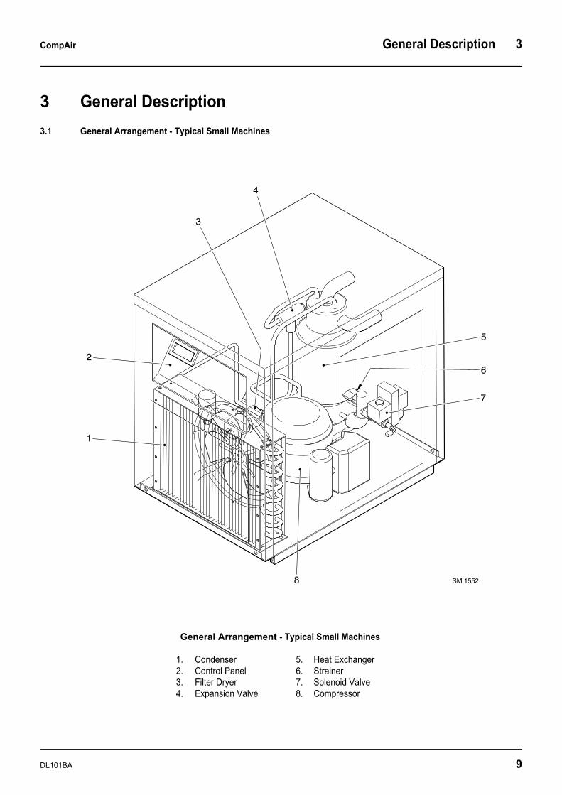
3 General Description3.1 General Arrangement - Typical Small Machines
1
2
3
4
5
6
7
8 SM 1552
General Arrangement - Typical Small Machines
1. Condenser2. Control Panel3. Filter Dryer4. Expansion Valve
5. Heat Exchanger6. Strainer7. Solenoid Valve8. Compressor
DL101BA 9
3 General Description CompAir
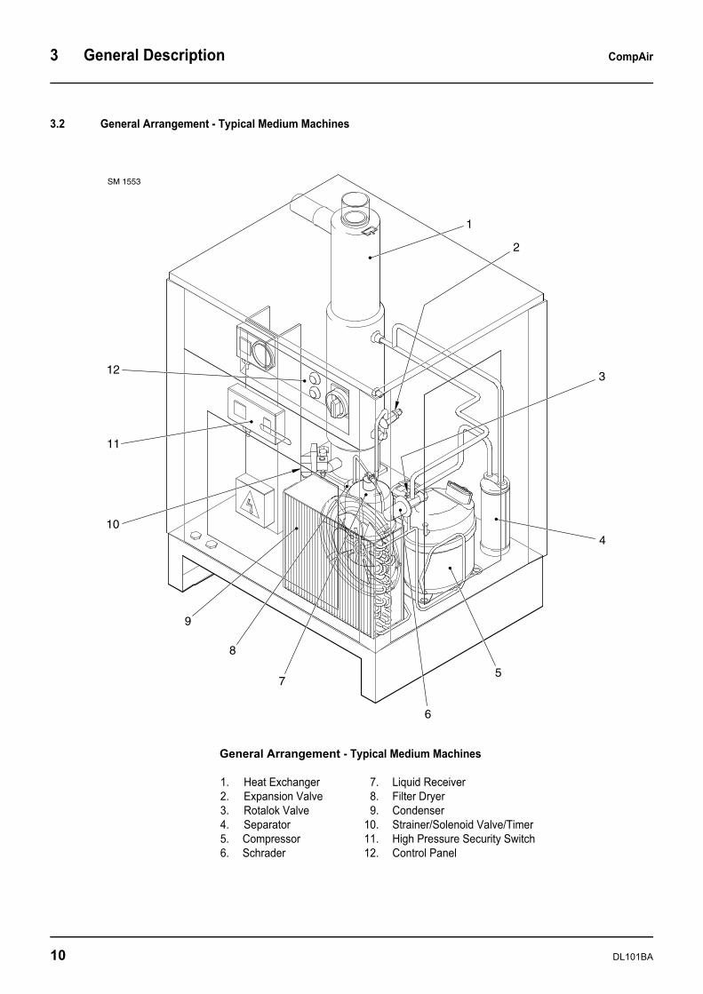
3.2 General Arrangement - Typical Medium Machines
SM 1553
1
2
3
4
5
6
7
8
9
10
11
12
General Arrangement - Typical Medium Machines
1. Heat Exchanger2. Expansion Valve3. Rotalok Valve4. Separator5. Compressor6. Schrader
7. Liquid Receiver8. Filter Dryer9. Condenser
10. Strainer/Solenoid Valve/Timer11. High Pressure Security Switch12. Control Panel
10 DL101BA
CompAir General Description 3
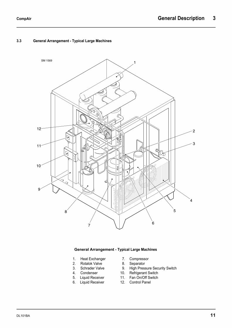
3.3 General Arrangement - Typical Large Machines
SM 15691
2
3
4
5
67
8
9
10
11
12
General Arrangement - Typical Large Machines
1. Heat Exchanger2. Rotalok Valve3. Schrader Valve4. Condenser5. Liquid Receiver6. Liquid Receiver
7. Compressor8. Separator9. High Pressure Security Switch
10. Refrigerant Switch11. Fan On/Off Switch12. Control Panel
DL101BA 11
3 General Description CompAir
3.4 Purpose Of This Dryer
This refrigerant compressed air dryer has been designed to remove moisture content from industrial compressed air that is free of any aggressive contaminants like ammonia, gaseous acid, dust, rust or any other chemical or mineral products capable of attacking or fouling the heat exchanger(s).
The optional water-cooled condenser is not designed to be used with seawater or water containing aggressive contaminants. Consult CompAir in case of doubt.
This dryer has been designed for indoor operation.
The minimum and maximum values stated must be adhered to, as well as the safety precautions described in this manual.
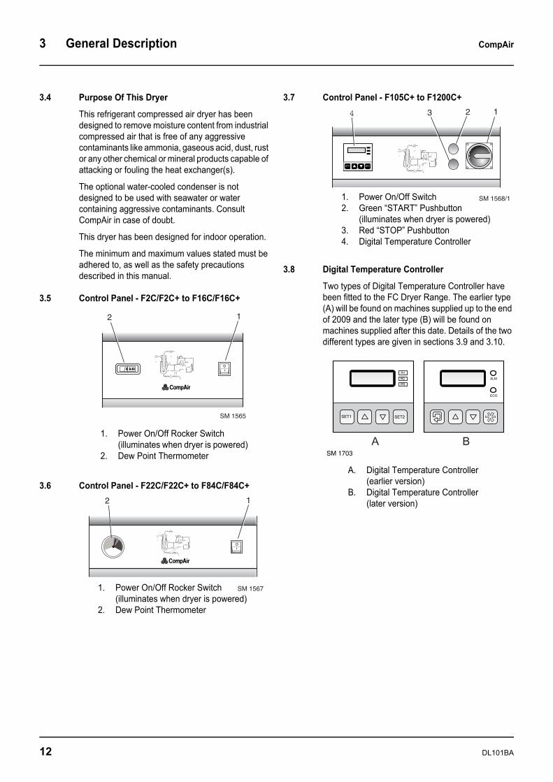
3.5 Control Panel - F2C/F2C+ to F16C/F16C+
3.6 Control Panel - F22C/F22C+ to F84C/F84C+
3.7 Control Panel - F105C+ to F1200C+
3.8 Digital Temperature Controller
Two types of Digital Temperature Controller have been fitted to the FC Dryer Range. The earlier type (A) will be found on machines supplied up to the end of 2009 and the later type (B) will be found on machines supplied after this date. Details of the two different types are given in sections 3.9 and 3.10.
2
SM 1565
1
1. Power On/Off Rocker Switch(illuminates when dryer is powered)
2. Dew Point Thermometer
2
SM 1567
1
1. Power On/Off Rocker Switch(illuminates when dryer is powered)
2. Dew Point Thermometer
SM 1568/1
134 2
1. Power On/Off Switch2. Green “START” Pushbutton
(illuminates when dryer is powered)3. Red “STOP” Pushbutton4. Digital Temperature Controller
R1
R2
PR
SET2SET1
ALM
ECO
SM 1703
A B
A. Digital Temperature Controller (earlier version)
B. Digital Temperature Controller (later version)
12 DL101BA
CompAir General Description 3
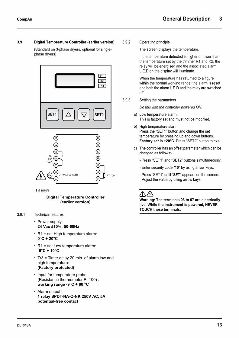
3.9 Digital Temperature Controller (earlier version)
(Standard on 3-phase dryers, optional for single-phase dryers)
3.9.1 Technical features
• Power supply: 24 Vac ±10%; 50-60Hz
• R1 = set High temperature alarm:0°C + 20°C
• R1 = set Low temperature alarm: -5°C + 10°C
• Tr3 = Timer delay 20 min. of alarm low and high temperature: (Factory protected)
• Input for temperature probe (Resistance thermometer Pt-100) : working range -9°C + 60 °C
• Alarm output: 1 relay SPDT-NA-O-NK 250V AC, 5A potential-free contact
3.9.2 Operating principle
The screen displays the temperature.
If the temperature detected is higher or lower than the temperature set by the trimmer R1 and R2, the relay will be energised and the associated alarm L.E.D on the display will illuminate.
When the temperature has returned to a figure within the normal working range, the alarm is reset and both the alarm L.E.D and the relay are switched off.
3.9.3 Setting the parameters
Do this with the controller powered ON:
a) Low temperature alarm:This is factory set and must not be modified.
b) High temperature alarm: Press the “SET1” button and change the set temperature by pressing up and down buttons. Factory set is +20°C. Press “SET2” button to exit.
c) The controller has an offset parameter which can be changed as follows:-
- Press “SET1” and “SET2” buttons simultaneously.
- Enter security code “10” by using arrow keys.
- Press “SET1” until “SFT” appears on the screen.Adjust the value by using arrow keys.
Warning: The terminals 03 to 07 are electrically live. While the instrument is powered, NEVER TOUCH these terminals.
01
02
03
04
05
06
07
15
16
17
18
19
20
21
3A250VAC
24 VAC; 50-60Hz PT-100
SM 1570/1
R1
R2
PR
SET2SET1
Digital Temperature Controller (earlier version)
DL101BA 13
3 General Description CompAir
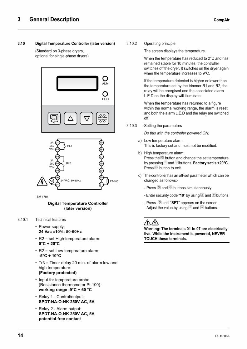
3.10 Digital Temperature Controller (later version)
(Standard on 3-phase dryers,optional for single-phase dryers)
3.10.1 Technical features
• Power supply: 24 Vac ±10%; 50-60Hz
• R2 = set High temperature alarm:0°C + 20°C
• R2 = set Low temperature alarm: -5°C + 10°C
• Tr3 = Timer delay 20 min. of alarm low and high temperature: (Factory protected)
• Input for temperature probe (Resistance thermometer Pt-100) : working range -9°C + 60 °C
• Relay 1 - Control/output:SPDT-NA-O-NK 250V AC, 5A
• Relay 2 - Alarm output: SPDT-NA-O-NK 250V AC, 5Apotential-free contact
3.10.2 Operating principle
The screen displays the temperature.
When the temperature has reduced to 2°C and has remained stable for 10 minutes, the controller switches off the dryer. It switches on the dryer again when the temperature increases to 9°C.
If the temperature detected is higher or lower than the temperature set by the trimmer R1 and R2, the relay will be energised and the associated alarm L.E.D on the display will illuminate.
When the temperature has returned to a figure within the normal working range, the alarm is reset and both the alarm L.E.D and the relay are switched off.
3.10.3 Setting the parameters
Do this with the controller powered ON:
a) Low temperature alarm:This is factory set and must not be modified.
b) High temperature alarm: Press the button and change the set temperature by pressing and buttons. Factory set is +20°C. Press button to exit.
c) The controller has an off-set parameter which can be changed as follows:-
- Press and buttons simultaneously.
- Enter security code “10” by using and buttons.
- Press until “SFT” appears on the screen. Adjust the value by using and buttons.
Warning: The terminals 01 to 07 are electrically live. While the instrument is powered, NEVER TOUCH these terminals.
RL1
RL2
01
02
03
04
05
06
07
15
16
17
18
19
20
21
3A250VAC
3A250VAC
24 VAC; 50-60Hz PT-100
SM 1704
ALM
ECO
Digital Temperature Controller (later version)
14 DL101BA
CompAir General Description 3
3.11 Energy Saving Devices (ESD)
The energy-saving device will switch the dryer OFF when there is no compressed air flow and ON again when the temperature sensor indicates +10 °C (adjustable). These important devices are offered because very often at night or weekend the air compressors are shut down but not the dryers.
3 types of ESD are offered:-
• ESD 1 - This is an optional extra available for single-phase dryers only and includes a digital dew point temperature meter in place of the standard colour zone thermometer.
• ESD 2 - This is fitted as standard to all 3-phase dryers and includes a digital dew point temperature meter.
• ESD 3 - This is an optional extra available for 3-phase dryers only. It includes a PLC display with clear text indication of dew point, alarms, maintenance and running hours in addition to automatic starting and stopping of the dryer on a signal from the tem-perature sensor as described above.
ESD3 functions are:
- Energy saving - Alarm message display- Running hours display- Energy saving hours display - Maintenance required display
a) Energy saving:
The dryer will automatically stop when the temperature in the heat exchanger has remained at 1°C or less for more than 10 minutes (meaning no load). When the temperature in the heat exchanger rises to 9°C, the dryer will restart and commence drying the air to the correct dewpoint once again. The temperature level can be adjusted via the digital thermometer. When in energy-saving mode, the display will show the message "energy saving dryer running OK"
b) Alarm message display:
In the event of a problem, the dryer will display a clear message of the alarm detected.
Alarms can be :-
- Phase inverted - Refrigerant High/Low pressure alarm - High temperature alarm - Thermal protection of the compressor
c) Hours display: Pressing the button on the front panel of PLC display repeatedly will move between dryer running hours, hours in energy saving mode and hours remaining until next maintenance.
d) Maintenance required display: When maintenance is needed, the display shows the message "maintenance needed, dryer running OK".
3.12 Starting and Stopping3.12.1 Single-phase Dryers
1) To Starta) Push the green rocker switch to “I” to start the dryer. b) The switch will illuminate to indicate that the dryer is
running. 2) To Stop
a) First, shut off the pressurised air flow through the dryer (either shut down the air compressor or close the inlet/outlet or by-pass valve).
b) Push the green rocker switch to “O” to stop the dryer. 3.12.2 3-phase dryers
1) Starting after a prolonged shut-down a) Set the rotary switch to "I" (ON): this preheats the
dryer. It is recommended that the dryer power is left on permanently so that the crankcase heater runs continuously. Caution: After the dryer has been shut down for a prolonged period it is MANDATORY to:-
(i) allow a preheating period of 4 hours minimum before starting the dryer again
(ii) avoid any compressed air flow during preheating.
b) Follow the daily starting and shut-down procedures. 2) Daily starting
a) Check that the rotary switch has been left at “I” after the previous run in order to keep the preheating on. If it has not, refer to section 1) above.
b) Press the green “START” button to start the dryer. The start button will illuminate to indicate that the dryer is running. Note: If the ambient temperature is over 35°C, continue pressing the start button until the temperature measured by the thermostatic switch at the compressor inlet is below 35°C (it will take about 1 minute).
3) Daily stoppinga) First, shut off the pressurised air flow through the
dryer (either shut down the air compressor or close the inlet/outlet or by-pass valve).
DL101BA 15

3 General Description CompAir
b) When the air flow has been shut off, press the red “STOP” button to stop the dryer.
c) To switch the already preheated dryer on again, simply press the green “START” button.
d) If shutting down for a prolonged period, or for maintenance, turn the rotary switch to "O" (OFF). When the dryer is in daily use, it is recommended to leave it at position "I" (ON) in order to keep the preheating on.
Caution: Avoid leaving the dryer stopped when compressed air is still flowing through it.
3.13 During operation Regularly check the position of the dew point indicator. The reference line has to be in the green zone. If not, read the appropriate action in the trouble-shooting section
3.14 Refrigerant Circuit: Description
The refrigerant circuit can be divided into three parts:-
• Low pressure section with an evaporator (heat exchanger)
• High pressure section including: condenser, liquid receiver (if installed) and the filter dryer.
• Control circuit including: compressor, expan-sion valve, by-pass valve (if installed), fan pressure switch, safety high pressure switch. Watercooled dryers are equipped with a water flow control valve.
Safety Devices : t : Compressor Thermo-
switch w : Fan Pressure Switch x : Crankcase Heater s : Inlet Prefilter u : Low Pressure Switch v : High Pressure Switch y : Liquid Separator z : Suction Thermo-
switch
Refrigerant Circuit :1 : Hermetic Compressor 2 : Aircooled Condenser 3 : Condenser Fan 4 : Liquid Receiver 5 : Filter Dryer 6 : Thermostatic
Expansion Valve 7 : Refrigerant Pressure 8 : Hot Gas By-pass
Valve
Air Circuit: A: Air/Air Exchanger B: Air/Refrigerant
Exchanger C: Refrigerated
Separator D: Manual Isolating
Valve and Drain (Bekomat zero-loss drain on + models)
Notes on safety devices:t,w: (all models) x: (F72C to F1200C+) s,u,v,y,z : (only for F156C+ to F1200C+ )
16
DL101BA
CompAir General Description 3
3.15 Refrigerant Circuit: Operation
The refrigerant circuit operates as follows:
The compressor compresses a refrigerant gas.
The hot refrigerant gas passes through a condenser where it liquifies. This liquid refrigerant is stored in the liquid receiver (if installed).
The liquid is drawn from the receiver and injected into the evaporator (heat exchanger) by an expansion valve. This expansion valve is protected by a filter which prevents particles and humidity from getting into the circuit.
The injected liquid fills the refrigerant section of the air/refrigerant heat exchanger where it is caused to evaporate as it removes the heat from the compressed air. The refrigerant gas is drawn into the compressor and the cycle repeats.
In order to keep the evaporation pressure constant, and thus the refrigerant temperature in the heat exchanger, a by-pass valve injects hot gaseous refrigerant in the circuit. On certain dryers, an automatic pressure expansion valve regulates this.
3.16 Compressed Air Circuit
The saturated hot compressed air flows into the air/ air heat exchanger where it is pre-cooled by the out-flowing dry chilled air. In the cold zone of the air refrigerant section, it continues to cool down to dew point and enters the separator where condensates are collected. The outgoing chilled air is then warmed up in the air/air heat exchanger by the hot incoming air.
The condensates are collected after centrifugal separation and drained out through the automatic trap.
As long as the compressed air temperature does not drop below dew point, there will be no condensation in the compressed air pipe.
3.17 Refrigerant Compressor
Being of the hermetic type, it requires no servicing.
3.18 Condenser
The air condenser is equipped with helicoidal fans which are controlled by a pressure switch which stops and starts the fans in order to maintain the refrigerant high pressure at the correct level.
If a water-cooled dryer is fitted, a water control valve piloted by refrigerant high pressure controls the water flow.
3.19 Refrigerant Circuit Protection
3.19.1 Overload protector
The single phase compressors are equipped with an overload protector which is a temperature switch which monitors the temperature of the compressor for overheating. In case of malfunction, the protector trips out but switches on again automatically as soon as the compressor has cooled down.
A warning lamp will light to indicate that the protector has tripped out.
3.19.2 High pressure protection switch
Refrigerant circuits are protected against excessive pressure by a protection switch that stops the compressor in case of excessive pressure. If this safety switch has trips out, it has to be manually reset before switching on the dryer.
3.19.3 Refrigerant liquid monitor
3-phase dryers are equipped with a temperature switch which controls the quantity of refrigerant in the dryer.
3.20 Filter-dryer
The refrigerant circuit is kept totally moisture-free by a filter-dryer which also traps any solid particles that may have accumulated in the circuit during assembly. To avoid problems, the refrigerant circuit must be evacuated by means of a vacuum pump before loading refrigerant.
3.21 Crankcase Heater
3-phase dryers are equipped with an electrical crankcase heater for preliminary pre-heating of the refrigerant compressor in order to evaporate any liquid refrigerant which may have condensed in the crankcase. This will avoid a liquid shock that can damage the compressor.
Note: Refer to important note related to pre-heating in section "Operation" of the user manual
3.22 Refrigerant Circuit Regulation - F2C To F16C
The liquid refrigerant is injected into the evaporator by a pressostatic expansion valve which maintains the refrigerant in the evaporator at a constant pressure.
This constant pressure corresponds to a stable evaporating temperature adjusted as close to 0 °C as possible.
DL101BA 17
3 General Description CompAir
3.23 Refrigerant Circuit Regulation - F22C To F1200C +
The evaporating pressure is kept constant by a controlled injection of hot gas from the high-pressure side into the low-pressure section of the circuit through a by-pass valve. This constant pressure corresponds to a stable evaporating temperature adjusted as close to 0 °C as possible.
The liquid refrigerant is injected into the evaporator through a thermostatic expansion valve to keep the superheat of refrigerant at the outlet of the evaporator constant.
The mix of hot gas from by-pass valve and cold gas from evaporator is called superheat and is adjusted at 10 ± 5 °C.
3.24 Condensate Drain-trap Assembly
Dismantling the drain is straightforward because it can be isolated from the air circuit under pressure using a ball valve. The drain has to be de-pressurised before being dismantled.
3.25 Heat Exchanger Modular Design
The dryers are equipped with compact monobloc heat exchanger modules. These are specially designed to dry compressed air and are comprised of:
An air/heat exchanger which pre-cools the entering hot compressed air using the out-flowing cold air.
An evaporator which is an air/refrigerant exchanger cooling down the compressed air.
A centrifugal separator concentrating all condensates and requiring no maintenance.
An integrated 5 micron grade pre-filter located in the air inlet manifold of dryers having two or more modules in parallel.
Up to type F105C+
3.26 Accessories
• Dewpoint indicator: Located on the control panel, this standard feature displays the value of the pressure dewpoint.
• Temperature switch: Located inside the dryer, this optional tem-perature switch is adjustable from 0 up to 35°C
• Volt-free contact: This standard feature is piloted by an elec-tronic digital thermometer on F105C+ dryers and above. The word "COMPUTER" is writ-ten on the corresponding cable going into the connection box.
• Remote control: A remote control box is installed in a sepa-rate terminal on F105C+ dryers and above in order to allow remote starting and stopping of the dryer.
• Digital temperature control device: This standard feature on 3-phase dryers monitors the dew point and sends a signal if the dew point is outside the acceptable range.
18 DL101BA
CompAir Initial Inspection 4
DL101BA 19
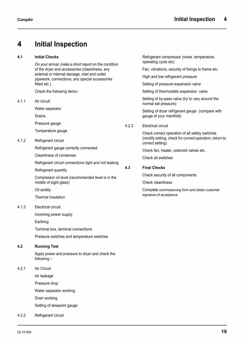
4 Initial Inspection
4.1 Initial Checks
On your arrival, make a short report on the condition of the dryer and accessories (cleanliness, any external or internal damage, inlet and outlet pipework, connections, any special accessories fitted etc.)
Check the following items:-
4.1.1 Air circuit
Water separator
Drains
Pressure gauge
Temperature gauge
4.1.2 Refrigerant circuit
Refrigerant gauge correctly connected
Cleanliness of condenser
Refrigerant circuit connections tight and not leaking
Refrigerant quantity
Compressor oil level (recommended level is in the middle of sight glass)
Oil acidity
Thermal insulation
4.1.3 Electrical circuit
Incoming power supply
Earthing
Terminal box, terminal connections
Pressure switches and temperature switches
4.2 Running Test
Apply power and pressure to dryer and check the following :-
4.2.1 Air Circuit
Air leakage
Pressure drop
Water separator working
Drain working
Setting of dewpoint gauge
4.2.2 Refrigerant circuit
Refrigerant compressor (noise, temperature, operating cycle etc)
Fan, vibrations, security of fixings to frame etc.
High and low refrigerant pressure
Setting of pressure expansion valve
Setting of thermostatic expansion valve
Setting of by-pass valve (try to vary around the normal set pressure)
Setting of dryer refrigerant gauge (compare with gauge of your manifold)
4.2.3 Electrical circuit
Check correct operation of all safety switches (modify setting, check for correct operation, return to correct setting)
Check fan, heater, solenoid valves etc.
Check all switches
4.3 Final Checks
Check security of all components
Check cleanliness
Complete commissioning form and obtain customer signature of acceptance
5 Typical Faults CompAir
20 DL101BA
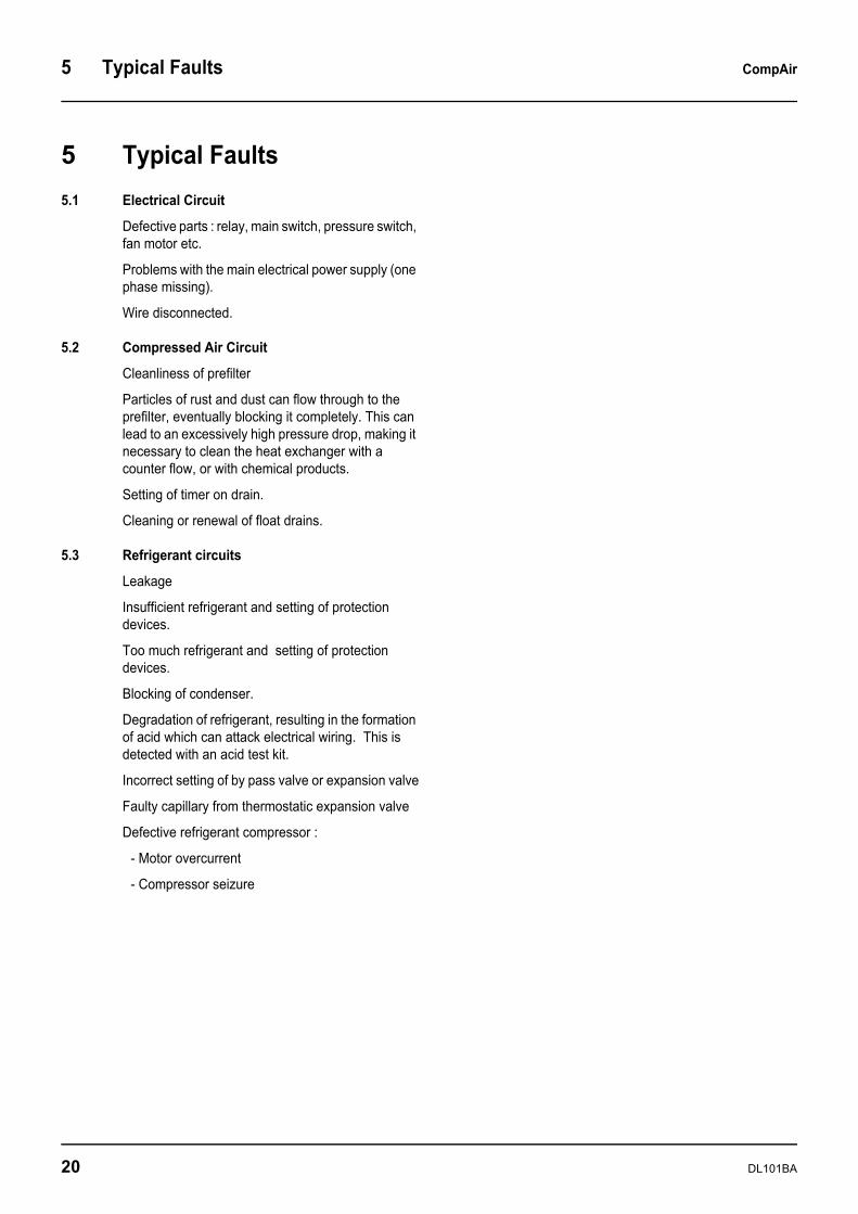
5 Typical Faults5.1 Electrical Circuit
Defective parts : relay, main switch, pressure switch, fan motor etc.
Problems with the main electrical power supply (one phase missing).
Wire disconnected.
5.2 Compressed Air Circuit
Cleanliness of prefilter
Particles of rust and dust can flow through to the prefilter, eventually blocking it completely. This can lead to an excessively high pressure drop, making it necessary to clean the heat exchanger with a counter flow, or with chemical products.
Setting of timer on drain.
Cleaning or renewal of float drains.
5.3 Refrigerant circuits
Leakage
Insufficient refrigerant and setting of protection devices.
Too much refrigerant and setting of protection devices.
Blocking of condenser.
Degradation of refrigerant, resulting in the formation of acid which can attack electrical wiring. This is detected with an acid test kit.
Incorrect setting of by pass valve or expansion valve
Faulty capillary from thermostatic expansion valve
Defective refrigerant compressor :
- Motor overcurrent
- Compressor seizure
CompAir Fault Finding 6
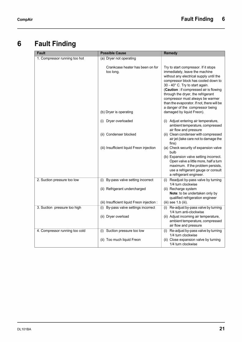
6 Fault FindingFault Possible Cause Remedy1. Compressor running too hot (a) Dryer not operating
Crankcase heater has been on for too long.
(b) Dryer is operating
(i) Dryer overloaded
(ii) Condenser blocked
(iii) Insufficient liquid Freon injection
Try to start compressor. If it stops immediately, leave the machine without any electrical supply until the compressor block has cooled down to 30 - 40° C. Try to start again.(Caution : if compressed air is flowing through the dryer, the refrigerant compressor must always be warmer than the evaporator. If not, there will be a danger of the compressor being damaged by liquid Freon).
(i) Adjust entering air temperature, ambient temperature, compressed air flow and pressure
(ii) Clean condenser with compressed air jet (take care not to damage the fins)
(a) Check security of expansion valve bulb
(b) Expansion valve setting incorrect. Open valve a little more, half a turn maximum. If the problem persists, use a refrigerant gauge or consult a refrigerant engineer.
2. Suction pressure too low (i) By-pass valve setting incorrect
(ii) Refrigerant undercharged
(iii) Insufficient liquid Freon injection :
(i) Readjust by-pass valve by turning 1/4 turn clockwise
(ii) Recharge systemNote: to be undertaken only by qualified refrigeration engineer
(iii) see 1.b (iii).3. Suction pressure too high (i) By-pass valve settings incorrect
(ii) Dryer overload
(i) Re-adjust by-pass valve by turning 1/4 turn anti-clockwise
(ii) Adjust incoming air temperature, ambient temperature, compressed air flow and pressure
4. Compressor running too cold (i) Suction pressure too low
(ii) Too much liquid Freon
(i) Re-adjust by-pass valve by turning 1/4 turn clockwise
(ii) Close expansion valve by turning 1/4 turn clockwise
DL101BA 21
6 Fault Finding CompAir
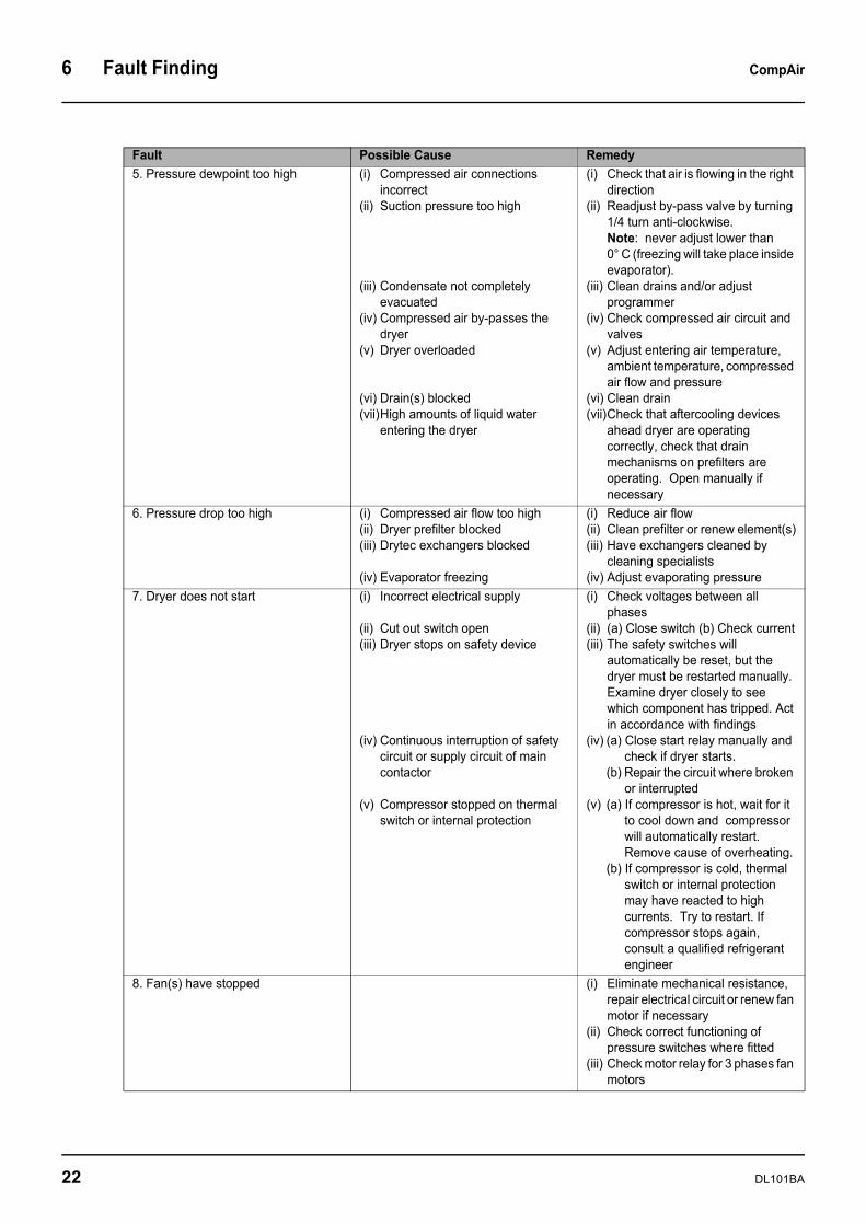
5. Pressure dewpoint too high (i) Compressed air connections incorrect
(ii) Suction pressure too high
(iii) Condensate not completely evacuated
(iv) Compressed air by-passes the dryer
(v) Dryer overloaded
(vi) Drain(s) blocked(vii)High amounts of liquid water
entering the dryer
(i) Check that air is flowing in the right direction
(ii) Readjust by-pass valve by turning 1/4 turn anti-clockwise. Note: never adjust lower than 0° C (freezing will take place inside evaporator).
(iii) Clean drains and/or adjust programmer
(iv) Check compressed air circuit and valves
(v) Adjust entering air temperature, ambient temperature, compressed air flow and pressure
(vi) Clean drain (vii)Check that aftercooling devices
ahead dryer are operating correctly, check that drain mechanisms on prefilters are operating. Open manually if necessary
6. Pressure drop too high (i) Compressed air flow too high(ii) Dryer prefilter blocked(iii) Drytec exchangers blocked
(iv) Evaporator freezing
(i) Reduce air flow(ii) Clean prefilter or renew element(s)(iii) Have exchangers cleaned by
cleaning specialists(iv) Adjust evaporating pressure
7. Dryer does not start (i) Incorrect electrical supply
(ii) Cut out switch open(iii) Dryer stops on safety device
(iv) Continuous interruption of safety circuit or supply circuit of main contactor
(v) Compressor stopped on thermal switch or internal protection
(i) Check voltages between all phases
(ii) (a) Close switch (b) Check current(iii) The safety switches will
automatically be reset, but the dryer must be restarted manually.Examine dryer closely to see which component has tripped. Act in accordance with findings
(iv) (a) Close start relay manually and check if dryer starts.
(b) Repair the circuit where broken or interrupted
(v) (a) If compressor is hot, wait for it to cool down and compressor will automatically restart. Remove cause of overheating.
(b) If compressor is cold, thermal switch or internal protection may have reacted to high currents. Try to restart. If compressor stops again, consult a qualified refrigerant engineer
8. Fan(s) have stopped (i) Eliminate mechanical resistance, repair electrical circuit or renew fan motor if necessary
(ii) Check correct functioning of pressure switches where fitted
(iii) Check motor relay for 3 phases fan motors
Fault Possible Cause Remedy
22 DL101BA
CompAir Maintenance 7
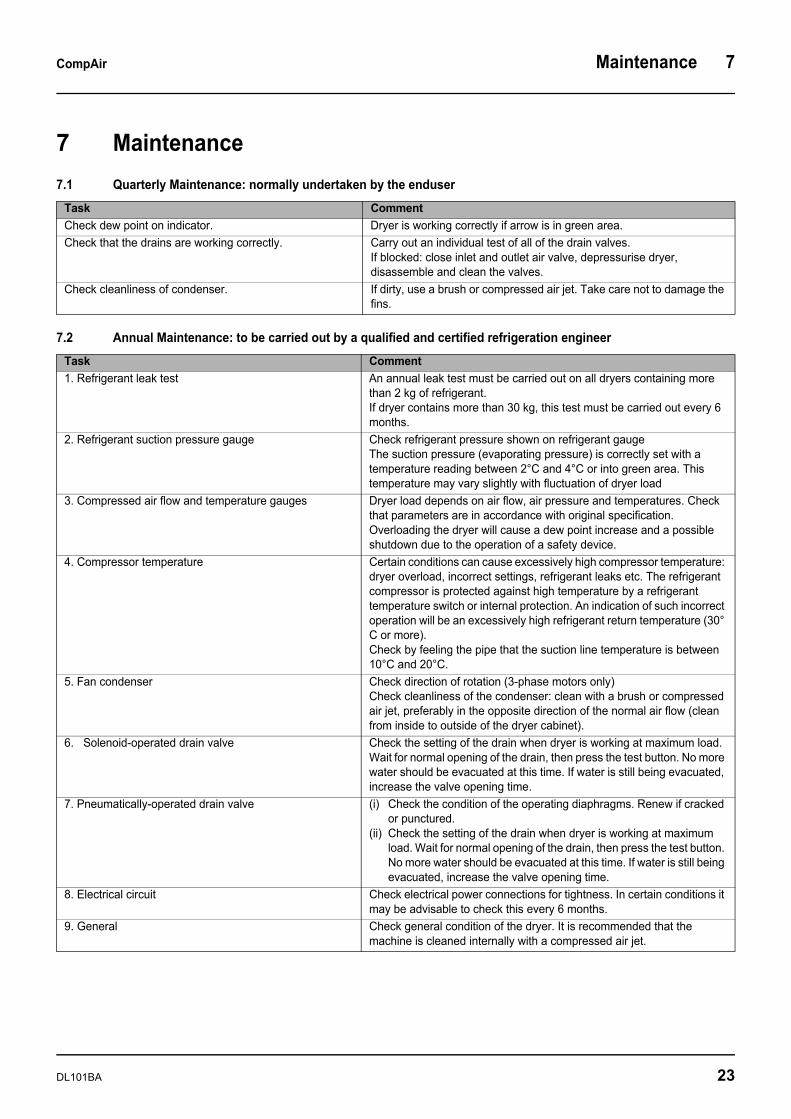
7 Maintenance7.1 Quarterly Maintenance: normally undertaken by the enduser
7.2 Annual Maintenance: to be carried out by a qualified and certified refrigeration engineer
Task CommentCheck dew point on indicator. Dryer is working correctly if arrow is in green area.Check that the drains are working correctly. Carry out an individual test of all of the drain valves.
If blocked: close inlet and outlet air valve, depressurise dryer, disassemble and clean the valves.
Check cleanliness of condenser. If dirty, use a brush or compressed air jet. Take care not to damage the fins.
Task Comment1. Refrigerant leak test An annual leak test must be carried out on all dryers containing more
than 2 kg of refrigerant.If dryer contains more than 30 kg, this test must be carried out every 6 months.
2. Refrigerant suction pressure gauge Check refrigerant pressure shown on refrigerant gaugeThe suction pressure (evaporating pressure) is correctly set with a temperature reading between 2°C and 4°C or into green area. This temperature may vary slightly with fluctuation of dryer load
3. Compressed air flow and temperature gauges Dryer load depends on air flow, air pressure and temperatures. Check that parameters are in accordance with original specification. Overloading the dryer will cause a dew point increase and a possible shutdown due to the operation of a safety device.
4. Compressor temperature Certain conditions can cause excessively high compressor temperature: dryer overload, incorrect settings, refrigerant leaks etc. The refrigerant compressor is protected against high temperature by a refrigerant temperature switch or internal protection. An indication of such incorrect operation will be an excessively high refrigerant return temperature (30° C or more). Check by feeling the pipe that the suction line temperature is between 10°C and 20°C.
5. Fan condenser Check direction of rotation (3-phase motors only) Check cleanliness of the condenser: clean with a brush or compressed air jet, preferably in the opposite direction of the normal air flow (clean from inside to outside of the dryer cabinet).
6. Solenoid-operated drain valve Check the setting of the drain when dryer is working at maximum load. Wait for normal opening of the drain, then press the test button. No more water should be evacuated at this time. If water is still being evacuated, increase the valve opening time.
7. Pneumatically-operated drain valve (i) Check the condition of the operating diaphragms. Renew if cracked or punctured.
(ii) Check the setting of the drain when dryer is working at maximum load. Wait for normal opening of the drain, then press the test button. No more water should be evacuated at this time. If water is still being evacuated, increase the valve opening time.
8. Electrical circuit Check electrical power connections for tightness. In certain conditions it may be advisable to check this every 6 months.
9. General Check general condition of the dryer. It is recommended that the machine is cleaned internally with a compressed air jet.
DL101BA 23
7 Maintenance CompAir
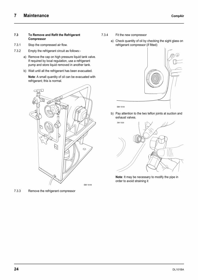
7.3 To Remove and Refit the Refrigerant Compressor
7.3.1 Stop the compressed air flow.
7.3.2 Empty the refrigerant circuit as follows:-
a) Remove the cap on high pressure liquid tank valve. If required by local regulation, use a refrigerant pump and store liquid removed in another tank.
b) Wait until all the refrigerant has been evacuated.
Note: A small quantity of oil can be evacuated with refrigerant; this is normal.
7.3.3 Remove the refrigerant compressor
7.3.4 Fit the new compressor
a) Check quantity of oil by checking the sight glass on refrigerant compressor (if fitted)
b) Pay attention to the two teflon joints at suction and exhaust valves.
Note: It may be necessary to modify the pipe in order to avoid straining it
SM 1518
SM 1519
SM 1520
24 DL101BA

CompAir Maintenance 7
7.3.5 Connect the electrical supply
a) Connect compressor to the mains.
Note: If a 3 phase machine, direction of rotation is not important.
b) Check voltage setting of crankcase heater
c) Connect heater and check it works
d) Install heater on the compressor
7.3.6 Replace the old dehydrator with an equivalent new one (old dehydrator contains an unknown quantity of water and must be changed)
7.3.7 Test refrigerant circuit for leakage
a) Inject refrigerant gas until a minimum of 2 bar pressure is reached
b) Detect with a soap bubble test first and then with an electronic leak detector
c) In case of leak, release pressure and repair
d) If there is no leakage, release gas
7.3.8 Connect the vacuum pump to the liquid tank
a) Check the vacuum on suction valve of refrigerant compressor with a pressure gauge
b) Let the vacuum pump run for 2 hours minimum (this allows humidity in refrigerant circuit to be removed). Check that pressure remaining in circuit is zero
SM 1521
SM 1522
SM 1523
SM 1525
DL101BA 25
7 Maintenance CompAir
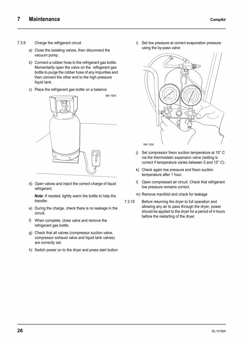
7.3.9 Charge the refrigerant circuit
a) Close the isolating valves, then disconnect the vacuum pump.
b) Connect a rubber hose to the refrigerant gas bottle. Momentarily open the valve on the refrigerant gas bottle to purge the rubber hose of any impurities and then connect the other end to the high pressure liquid tank.
c) Place the refrigerant gas bottle on a balance
d) Open valves and inject the correct charge of liquid refrigerant.
Note: If needed, lightly warm the bottle to help the transfer.
e) During the charge, check there is no leakage in the circuit.
f) When complete, close valve and remove the refrigerant gas bottle.
g) Check that all valves (compressor suction valve, compressor exhaust valve and liquid tank valves) are correctly set.
h) Switch power on to the dryer and press start button
i) Set low pressure at correct evaporation pressure using the by-pass valve
j) Set compressor freon suction temperature at 10° C via the thermostatic expansion valve (setting is correct if temperature varies between 5 and 15° C).
k) Check again low pressure and freon suction temperature after 1 hour.
l) Open compressed air circuit. Check that refrigerant low pressure remains correct.
m) Remove manifold and check for leakage
7.3.10 Before returning the dryer to full operation and allowing any air to pass through the dryer, power should be applied to the dryer for a period of 4 hours before the restarting of the dryer.
15150
SM 1524
-1
0
1
2
34
5
6
7
8
170
5
10
1520
25
30
34
SM 1526
26 DL101BA
CompAir Maintenance 7
7.4 Refrigerant Filling Procedure
7.4.1 Precautions regarding vacuum and moisture
Moisture or atmospheric air must be considered as the enemy of a refrigerant circuit.
Filling a dryer with a full refrigerant charge is normally carried out with the refrigerant system under vacuum.
Caution: It is extremely important never to fill a dryer if the engineer suspects that some atmospheric air or moisture may remain in the refrigerant circuit.
In such a case, the engineer must replace the dehydrator and apply a vacuum to the refrigerant circuit in order to remove all the air and moisture that may remain.
Only then is it permitted to commence filling the dryer with refrigerant.
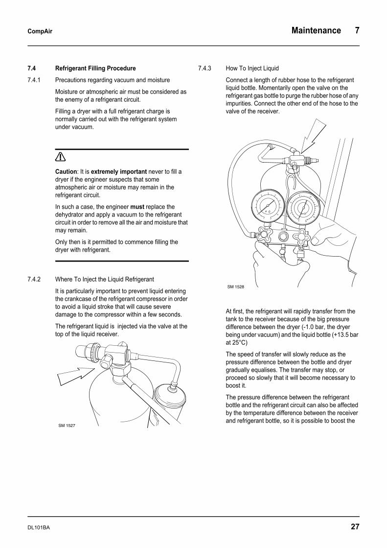
7.4.2 Where To Inject the Liquid Refrigerant
It is particularly important to prevent liquid entering the crankcase of the refrigerant compressor in order to avoid a liquid stroke that will cause severe damage to the compressor within a few seconds.
The refrigerant liquid is injected via the valve at the top of the liquid receiver.
7.4.3 How To Inject Liquid
Connect a length of rubber hose to the refrigerant liquid bottle. Momentarily open the valve on the refrigerant gas bottle to purge the rubber hose of any impurities. Connect the other end of the hose to the valve of the receiver.
At first, the refrigerant will rapidly transfer from the tank to the receiver because of the big pressure difference between the dryer (-1.0 bar, the dryer being under vacuum) and the liquid bottle (+13.5 bar at 25°C)
The speed of transfer will slowly reduce as the pressure difference between the bottle and dryer gradually equalises. The transfer may stop, or proceed so slowly that it will become necessary to boost it.
The pressure difference between the refrigerant bottle and the refrigerant circuit can also be affected by the temperature difference between the receiver and refrigerant bottle, so it is possible to boost the
SM 1527
-1
0
1
2
34
5
6
7
8
170
5
10
1520
25
30
34
SM 1528
DL101BA 27
7 Maintenance CompAir
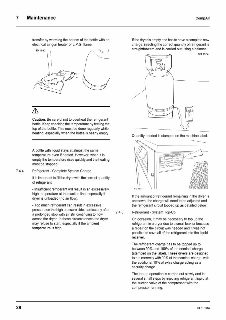
transfer by warming the bottom of the bottle with an electrical air gun heater or L.P.G. flame.
Caution: Be careful not to overheat the refrigerant bottle. Keep checking the temperature by feeling the top of the bottle. This must be done regularly while heating, especially when the bottle is nearly empty.
A bottle with liquid stays at almost the same temperature even if heated. However, when it is empty the temperature rises quickly and the heating must be stopped.
7.4.4 Refrigerant - Complete System Charge
It is important to fill the dryer with the correct quantity of refrigerant.
- Insufficient refrigerant will result in an excessively high temperature at the suction line, especially if dryer is unloaded (no air flow).
- Too much refrigerant can result in excessive pressure on the high pressure side, particularly after a prolonged stop with air still continuing to flow across the dryer. In these circumstances the dryer may refuse to start, especially if the ambient temperature is high.
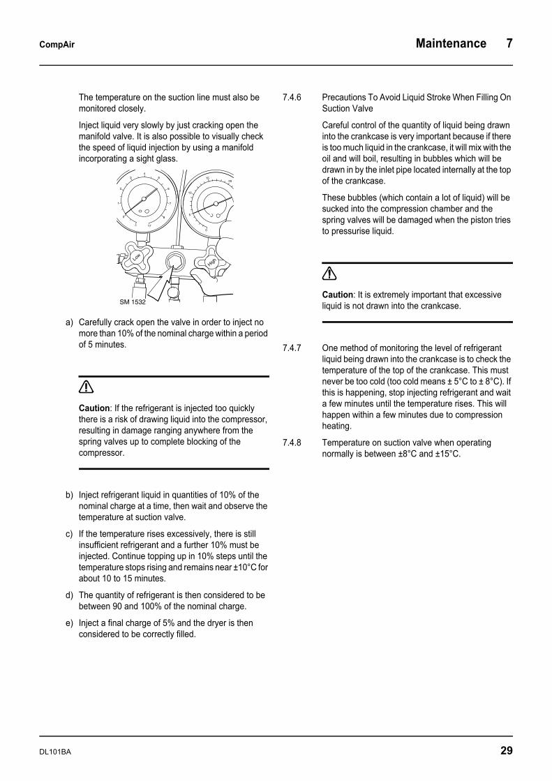
If the dryer is empty and has to have a complete new charge, injecting the correct quantity of refrigerant is straightforward and is carried out using a balance.
Quantity needed is stamped on the machine label.
If the amount of refrigerant remaining in the dryer is unknown, the charge will need to be adjusted and the refrigerant circuit topped up as detailed below.
7.4.5 Refrigerant - System Top-Up
On occasion, it may be necessary to top up the refrigerant in a dryer due to a small leak or because a repair on the circuit was needed and it was not possible to save all of the refrigerant into the liquid receiver.
The refrigerant charge has to be topped up to between 90% and 100% of the nominal charge (stamped on the label). These dryers are designed to run correctly with 90% of the nominal charge, with the additional 10% of extra charge acting as a security charge.
The top-up operation is carried out slowly and in several small steps by injecting refrigerant liquid at the suction valve of the compressor with the compressor running.
SM 1530
15150
SM 1524
COMPRESSED AIR DRYER
SM 1531
28 DL101BA
CompAir Maintenance 7
The temperature on the suction line must also be monitored closely.
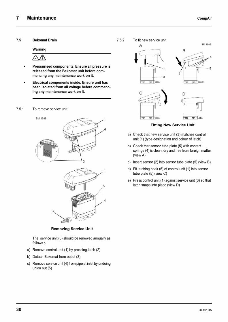
Inject liquid very slowly by just cracking open the manifold valve. It is also possible to visually check the speed of liquid injection by using a manifold incorporating a sight glass.
a) Carefully crack open the valve in order to inject no more than 10% of the nominal charge within a period of 5 minutes.
Caution: If the refrigerant is injected too quickly there is a risk of drawing liquid into the compressor, resulting in damage ranging anywhere from the spring valves up to complete blocking of the compressor.
b) Inject refrigerant liquid in quantities of 10% of the nominal charge at a time, then wait and observe the temperature at suction valve.
c) If the temperature rises excessively, there is still insufficient refrigerant and a further 10% must be injected. Continue topping up in 10% steps until the temperature stops rising and remains near ±10°C for about 10 to 15 minutes.
d) The quantity of refrigerant is then considered to be between 90 and 100% of the nominal charge.
e) Inject a final charge of 5% and the dryer is then considered to be correctly filled.
7.4.6 Precautions To Avoid Liquid Stroke When Filling On Suction Valve
Careful control of the quantity of liquid being drawn into the crankcase is very important because if there is too much liquid in the crankcase, it will mix with the oil and will boil, resulting in bubbles which will be drawn in by the inlet pipe located internally at the top of the crankcase.
These bubbles (which contain a lot of liquid) will be sucked into the compression chamber and the spring valves will be damaged when the piston tries to pressurise liquid.
Caution: It is extremely important that excessive liquid is not drawn into the crankcase.
7.4.7 One method of monitoring the level of refrigerant liquid being drawn into the crankcase is to check the temperature of the top of the crankcase. This must never be too cold (too cold means ± 5°C to ± 8°C). If this is happening, stop injecting refrigerant and wait a few minutes until the temperature rises. This will happen within a few minutes due to compression heating.
7.4.8 Temperature on suction valve when operating normally is between ±8°C and ±15°C.
-1
0
1
2
34
5
6
7
8
170
5
10
1520
Low
High
SM 1532
DL101BA 29
7 Maintenance CompAir
7.5 Bekomat Drain
Warning
• Pressurised components. Ensure all pressure is released from the Bekomat unit before com-mencing any maintenance work on it.
• Electrical components inside. Ensure unit has been isolated from all voltage before commenc-ing any maintenance work on it.
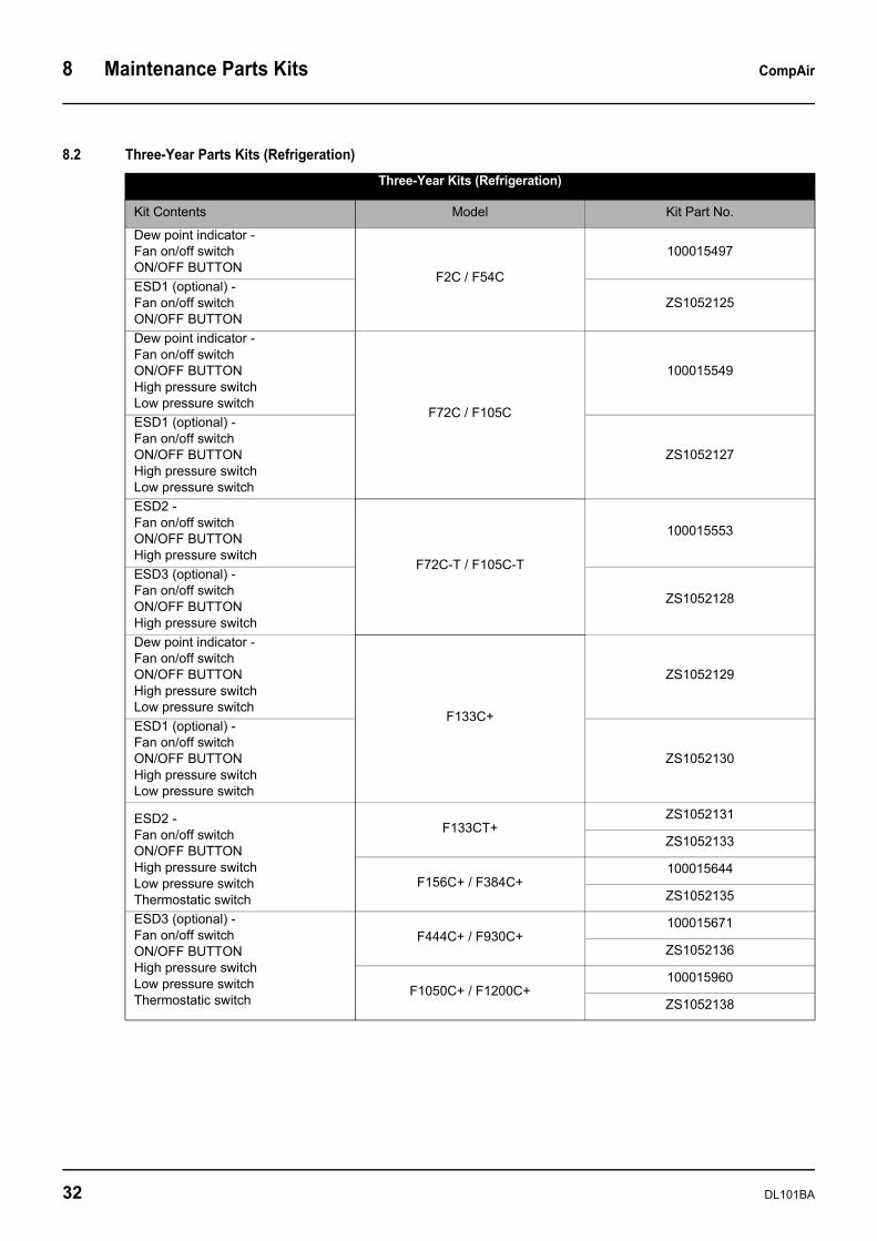
7.5.1 To remove service unit
The service unit (5) should be renewed annually as follows :-
a) Remove control unit (1) by pressing latch (2)
b) Detach Bekomat from outlet (3)
c) Remove service unit (4) from pipe at inlet by undoing union nut (5)
7.5.2 To fit new service unit
a) Check that new service unit (3) matches control unit (1) (type designation and colour of latch)
b) Check that sensor tube plate (5) with contact springs (4) is clean, dry and free from foreign matter (view A)
c) Insert sensor (2) into sensor tube plate (5) (view B)
d) Fit latching hook (6) of control unit (1) into sensor tube plate (5) (view C)
e) Press control unit (1) against service unit (3) so that latch snaps into place (view D)
�
�
�
�
�
�
�
�� ��
Removing Service Unit
�
�
� �
�
�
�
�
�� � �
Fitting New Service Unit
30 DL101BA

CompAir Maintenance Parts Kits 8
8 Maintenance Parts Kits8.1 One-Year Parts Kits
One-Year Kits
Kit Contents Model Kit Part No.
Timer drain valve F2C - F84C 100015495
Bekomat 31 service unit (optional) F2C+ - F84C+ (Optional) 100012735
Timer drain valve F72C / F84C 100015495
Bekomat 31 service unit (optional) F72C+ / F84C+ (Optional) 100012410
Bekomat 31 service unit F72CT+ / F84CT+ 100012410
Filter element(s)
F105C+ / F105CT+ 100015564
F133C+ / F133CT+ - F183CT+ 100012410
F210C+ / F285C+100015654
100012410
F348C+ / F384C+100015664
100012410
F444C+100015654100015564
2 * 100012410
F522C+100015654
Bekomat 32 service unit 100012410
F678C+100015664100015654
2 * 100012410
F780C+2 * 100015664
2 * 100012410
F930C+ / F1050C+100015654
2 * 100015664
3 * 100012410
F1200C+3 * 100015664
3 * 100012410
DL101BA 31
8 Maintenance Parts Kits CompAir
8.2 Three-Year Parts Kits (Refrigeration)
Three-Year Kits (Refrigeration)
Kit Contents Model Kit Part No.
Dew point indicator - Fan on/off switchON/OFF BUTTON
F2C / F54C
100015497
ESD1 (optional) - Fan on/off switchON/OFF BUTTON
ZS1052125
Dew point indicator - Fan on/off switchON/OFF BUTTONHigh pressure switchLow pressure switch
F72C / F105C
100015549
ESD1 (optional) - Fan on/off switchON/OFF BUTTONHigh pressure switchLow pressure switch
ZS1052127
ESD2 - Fan on/off switchON/OFF BUTTONHigh pressure switch
F72C-T / F105C-T
100015553
ESD3 (optional) -Fan on/off switchON/OFF BUTTONHigh pressure switch
ZS1052128
Dew point indicator - Fan on/off switchON/OFF BUTTONHigh pressure switchLow pressure switch
F133C+
ZS1052129
ESD1 (optional) - Fan on/off switchON/OFF BUTTONHigh pressure switchLow pressure switch
ZS1052130
ESD2 - Fan on/off switchON/OFF BUTTONHigh pressure switchLow pressure switchThermostatic switch
F133CT+ZS1052131
ZS1052133
F156C+ / F384C+100015644
ZS1052135
ESD3 (optional) -Fan on/off switchON/OFF BUTTONHigh pressure switchLow pressure switchThermostatic switch
F444C+ / F930C+100015671
ZS1052136
F1050C+ / F1200C+100015960
ZS1052138
32 DL101BA

CompAir Maintenance Parts Kits 8
8.3 Three-year Parts Kits for Fan
8.4 Five-year Parts Kits
Three-year Kits for Fan
Kit Contents Model Kit Part No.
Fan Motor Assembly F2C / F22C (50 - 60Hz) 100015498
F26C (50 - 60Hz) 100015530
Fan Motor AssemblyELKO VNT 25-40 F36C / F54C (50 - 60Hz) 100015534
Fan Motor Assembly F72C / F84C (50 - 60Hz) 100015550
F72C-T / F84C-T (50Hz) 100015554
F72C-T / F84C-T (60Hz) ZS1052139
F105C+ / F133C+ (50 - 60Hz) ZS1052140
F105CT+ / F133CT+ (50 - 60Hz) ZS1052141
F156C+ / F285C+ (50 - 60Hz) ZS1052142
F348C+ / F384C+ (50 - 60Hz) 100015666
F444C+ / F522C+ (50 - 60Hz) 100015672
F678C+ / F780C+ (50Hz) 100015681
F678C+ / F780C+ (60Hz) ZS1052143
F930C+ / F1200C+ (50Hz) 100015688
F930C+ / F1200C+ (60Hz) 100015688
Five-year Kit
Kit Contents Model Kit Part No.
Dryer - Expansion Valve F2C / F16C 100015498
Dryer - Expansion ValveBy-Pass Valve
F22C / F26C 100015526
F36C 100015534
F45C / F54C 100015543
F72C / F72C-T 100015551
F84C / 105CF84C-T / 105C-T 100015551
F133C+ ZS1052144
F156C+ / F240C+ 100015646
F285C+ 100015663
F348C+ / F384C+ 100015667
F444C+ / F522C+ 100015673
F678C+ / F780C+ 100015682
F930C+ / F1050C+ 100015689
F1200C+ 100015695
DL101BA 33
8 Maintenance Parts Kits CompAir
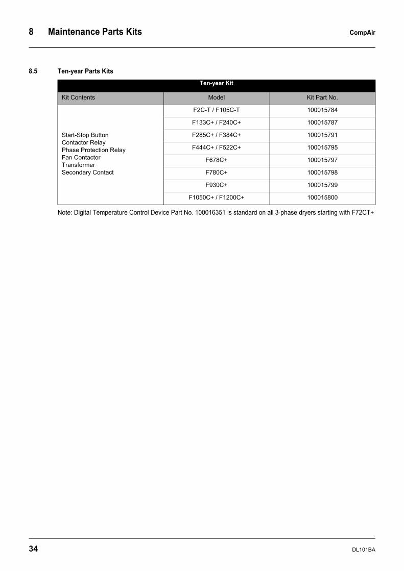
8.5 Ten-year Parts Kits
Note: Digital Temperature Control Device Part No. 100016351 is standard on all 3-phase dryers starting with F72CT+
Ten-year Kit
Kit Contents Model Kit Part No.
Start-Stop ButtonContactor RelayPhase Protection RelayFan ContactorTransformerSecondary Contact
F2C-T / F105C-T 100015784
F133C+ / F240C+ 100015787
F285C+ / F384C+ 100015791
F444C+ / F522C+ 100015795
F678C+ 100015797
F780C+ 100015798
F930C+ 100015799
F1050C+ / F1200C+ 100015800
34 DL101BA
CompAir Installation and Electrical Diagrams 9
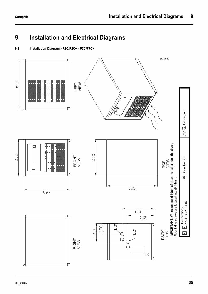
9 Installation and Electrical Diagrams9.1 Installation Diagram - F2C/F2C+ - F7C/F7C+
SM 1540
IMPO
RTAN
T: W
e re
com
men
d 50
cm o
f cle
aran
ce a
ll ar
ound
the
drye
r. Fl
oor f
ixin
g sc
rew
s ar
e lo
cate
d in
to Ø
14m
m.
Con
nect
ions
1/2
F BS
P PN
16
Dra
in 1
/4 B
SPC
oolin
g ai
r
DL101BA 35
9 Installation and Electrical Diagrams CompAir
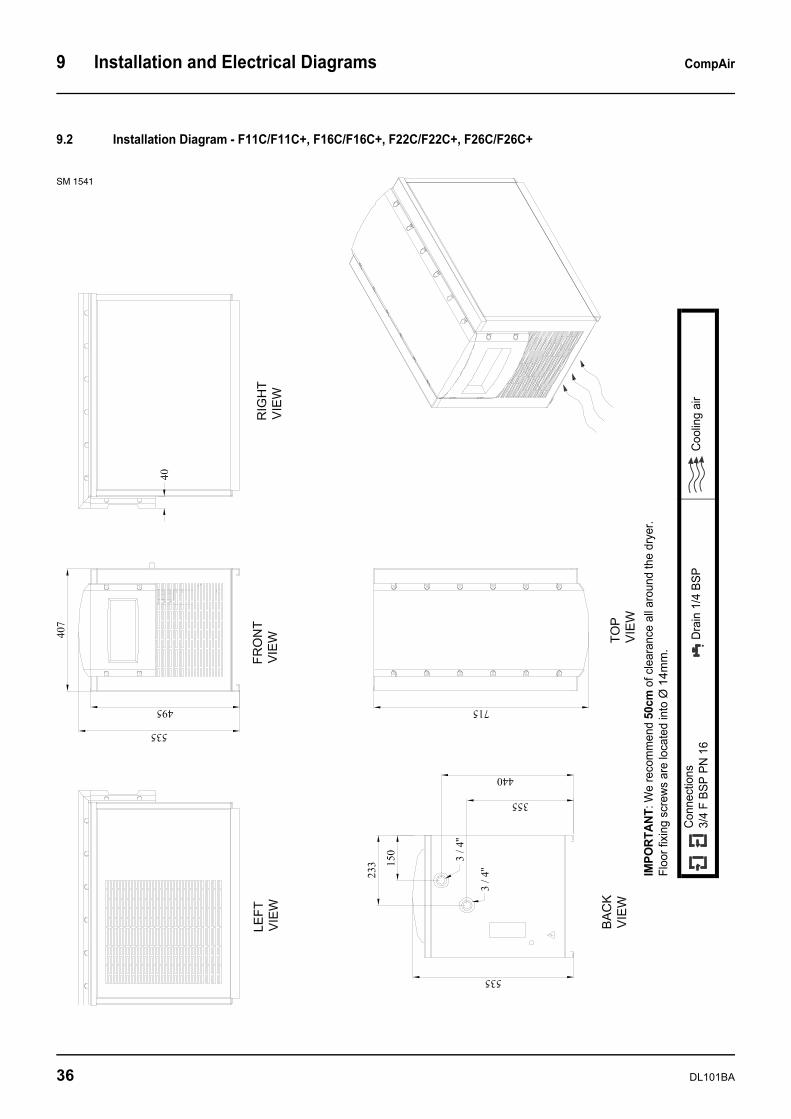
9.2 Installation Diagram - F11C/F11C+, F16C/F16C+, F22C/F22C+, F26C/F26C+
SM 1541
IMPO
RTAN
T: W
e re
com
men
d 50
cm o
f cle
aran
ce a
ll ar
ound
the
drye
r. Fl
oor f
ixin
g sc
rew
s ar
e lo
cate
d in
to Ø
14m
m.
Con
nect
ions
3/4
F BS
P PN
16
Dra
in 1
/4 B
SPC
oolin
g ai
r
36 DL101BA
CompAir Installation and Electrical Diagrams 9
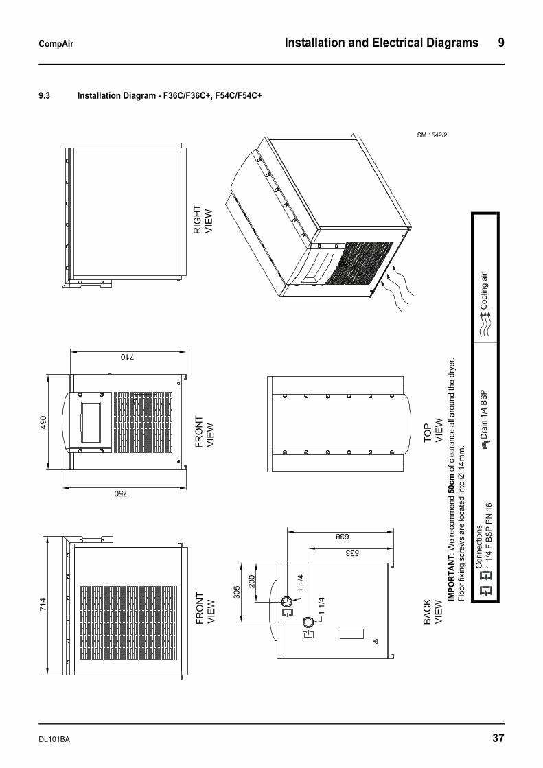
9.3 Installation Diagram - F36C/F36C+, F54C/F54C+
SM 1542/2
750
305 20
0
533
638
714
710
1 1/
4
1 1/
4
490
IMPO
RTAN
T: W
e re
com
men
d 50
cm o
f cle
aran
ce a
ll ar
ound
the
drye
r. Fl
oor f
ixin
g sc
rew
s ar
e lo
cate
d in
to Ø
14m
m.
Con
nect
ions
1 1/
4 F
BSP
PN 1
6D
rain
1/4
BSP
Coo
ling
air
DL101BA 37
9 Installation and Electrical Diagrams CompAir
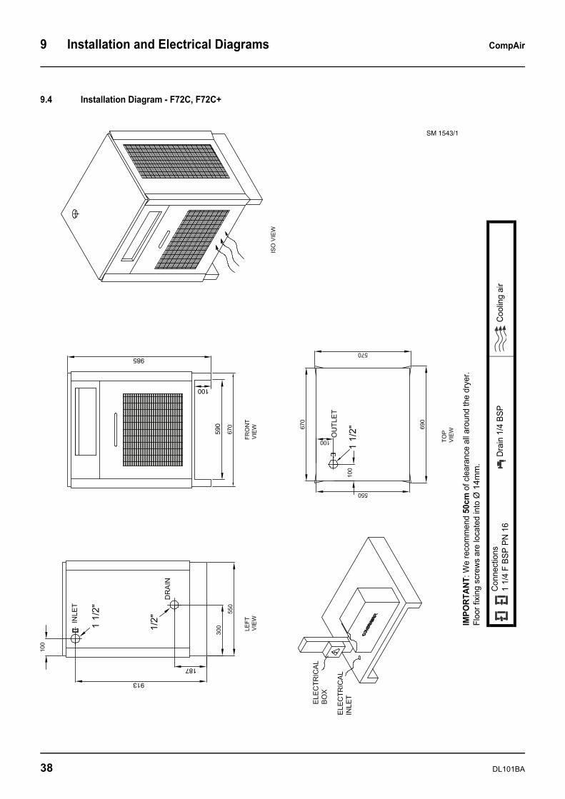
9.4 Installation Diagram - F72C, F72C+
SM 1543/1
913
187
985
590
100
IMPO
RTAN
T: W
e re
com
men
d 50
cm o
f cle
aran
ce a
ll ar
ound
the
drye
r. Fl
oor f
ixin
g sc
rew
s ar
e lo
cate
d in
to Ø
14m
m.
Con
nect
ions
1 1/
4 F
BSP
PN 1
6D
rain
1/4
BSP
Coo
ling
air
38 DL101BA
CompAir Installation and Electrical Diagrams 9
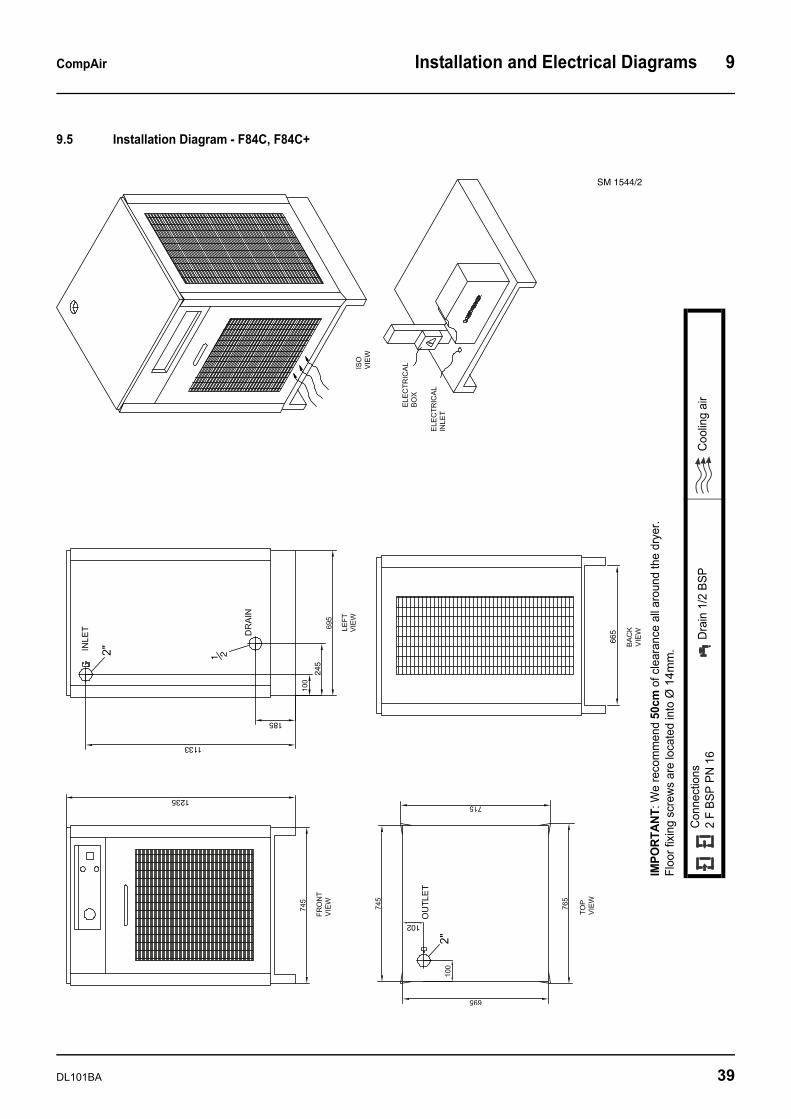
9.5 Installation Diagram - F84C, F84C+
SM 1544/2
1 2
1133
185
245
665
102
1235
IMPO
RTAN
T: W
e re
com
men
d 50
cm o
f cle
aran
ce a
ll ar
ound
the
drye
r. Fl
oor f
ixin
g sc
rew
s ar
e lo
cate
d in
to Ø
14m
m.
Con
nect
ions
2 F
BSP
PN 1
6D
rain
1/2
BSP
Coo
ling
air
DL101BA 39
9 Installation and Electrical Diagrams CompAir
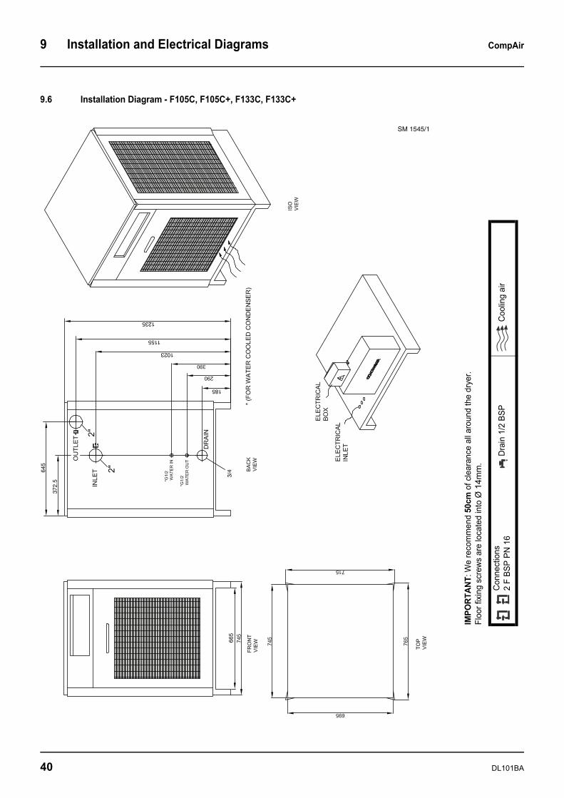
9.6 Installation Diagram - F105C, F105C+, F133C, F133C+
SM 1545/1
665
185
1023
1155
1235
372.
5
645
3/4
IMPO
RTAN
T: W
e re
com
men
d 50
cm o
f cle
aran
ce a
ll ar
ound
the
drye
r. Fl
oor f
ixin
g sc
rew
s ar
e lo
cate
d in
to Ø
14m
m.
Con
nect
ions
2 F
BSP
PN 1
6D
rain
1/2
BSP
Coo
ling
air
40 DL101BA
CompAir Installation and Electrical Diagrams 9
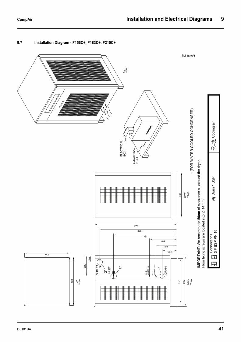
9.7 Installation Diagram - F156C+, F183C+, F210C+
SM 1546/1
322
1
225
1134
1348
1440
800
720
IMPO
RTAN
T: W
e re
com
men
d 50
cm o
f cle
aran
ce a
ll ar
ound
the
drye
r. Fl
oor f
ixin
g sc
rew
s ar
e lo
cate
d in
to Ø
14m
m.
Con
nect
ions
3 F
BSP
PN 1
6D
rain
1 B
SPC
oolin
g ai
r
DL101BA 41
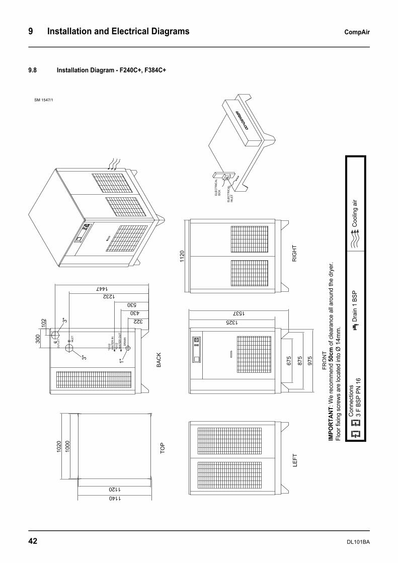
9 Installation and Electrical Diagrams CompAir
9.8 Installation Diagram - F240C+, F384C+
SM 1547/1
IMPO
RTAN
T: W
e re
com
men
d 50
cm o
f cle
aran
ce a
ll ar
ound
the
drye
r. Fl
oor f
ixin
g sc
rew
s ar
e lo
cate
d in
to Ø
14m
m.
Con
nect
ions
3 F
BSP
PN 1
6D
rain
1 B
SPC
oolin
g ai
r
42 DL101BA

CompAir Installation and Electrical Diagrams 9
9.9 Installation Diagram - F444C+, F522C+
FR
ON
T
CO
ND
EN
SE
R
SM 1548/1
IMPO
RTAN
T: W
e re
com
men
d 50
cm o
f cle
aran
ce a
ll ar
ound
the
drye
r. Fl
oor f
ixin
g sc
rew
s ar
e lo
cate
d in
to Ø
14m
m.
Con
nect
ions
4 F
BSP
PN 1
6D
rain
1 B
SPC
oolin
g ai
r
DL101BA 43
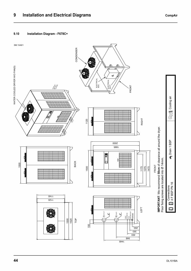
9 Installation and Electrical Diagrams CompAir
9.10 Installation Diagram - F678C+
FR
ON
T
CO
ND
EN
SE
R
SM 1549/1
IMPO
RTAN
T: W
e re
com
men
d 50
cm o
f cle
aran
ce a
ll ar
ound
the
drye
r. Fl
oor f
ixin
g sc
rew
s ar
e lo
cate
d in
to Ø
14m
m.
Con
nect
ions
4 F
BSP
PN 1
6D
rain
1 B
SPC
oolin
g ai
r
44 DL101BA
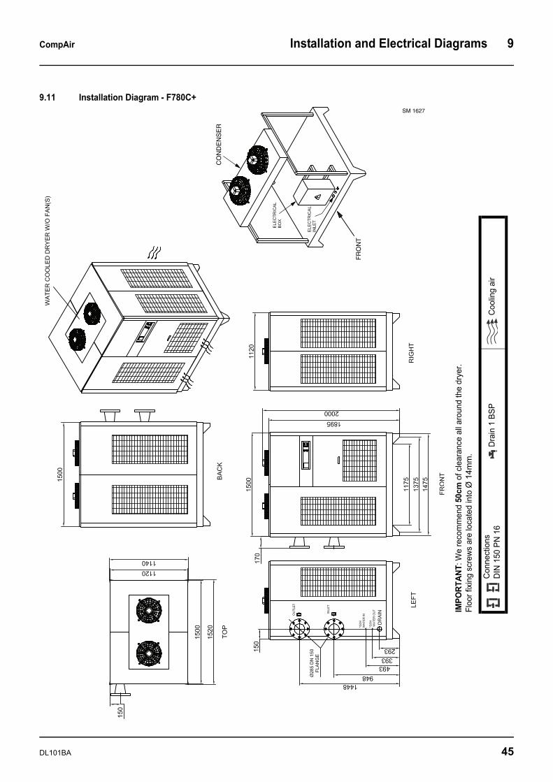
CompAir Installation and Electrical Diagrams 9
9.11 Installation Diagram - F780C+
CO
ND
EN
SE
R
FR
ON
T
SM 1627
IMPO
RTAN
T: W
e re
com
men
d 50
cm o
f cle
aran
ce a
ll ar
ound
the
drye
r. Fl
oor f
ixin
g sc
rew
s ar
e lo
cate
d in
to Ø
14m
m.
Con
nect
ions
DIN
150
PN
16
Dra
in 1
BSP
Coo
ling
air
DL101BA 45
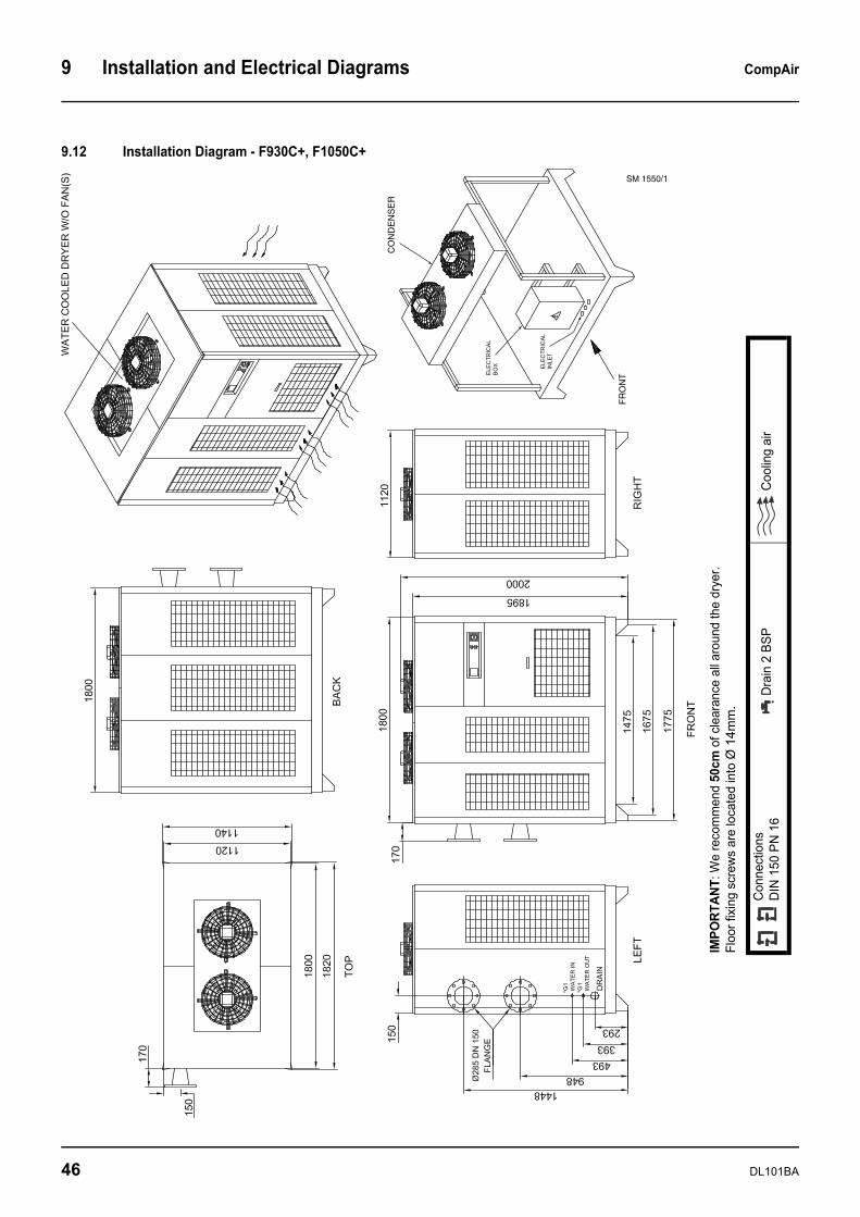
9 Installation and Electrical Diagrams CompAir
9.12 Installation Diagram - F930C+, F1050C+
FR
ON
T
CO
ND
EN
SE
R
SM 1550/1
IMPO
RTAN
T: W
e re
com
men
d 50
cm o
f cle
aran
ce a
ll ar
ound
the
drye
r. Fl
oor f
ixin
g sc
rew
s ar
e lo
cate
d in
to Ø
14m
m.
Con
nect
ions
DIN
150
PN
16
Dra
in 2
BSP
Coo
ling
air
46 DL101BA
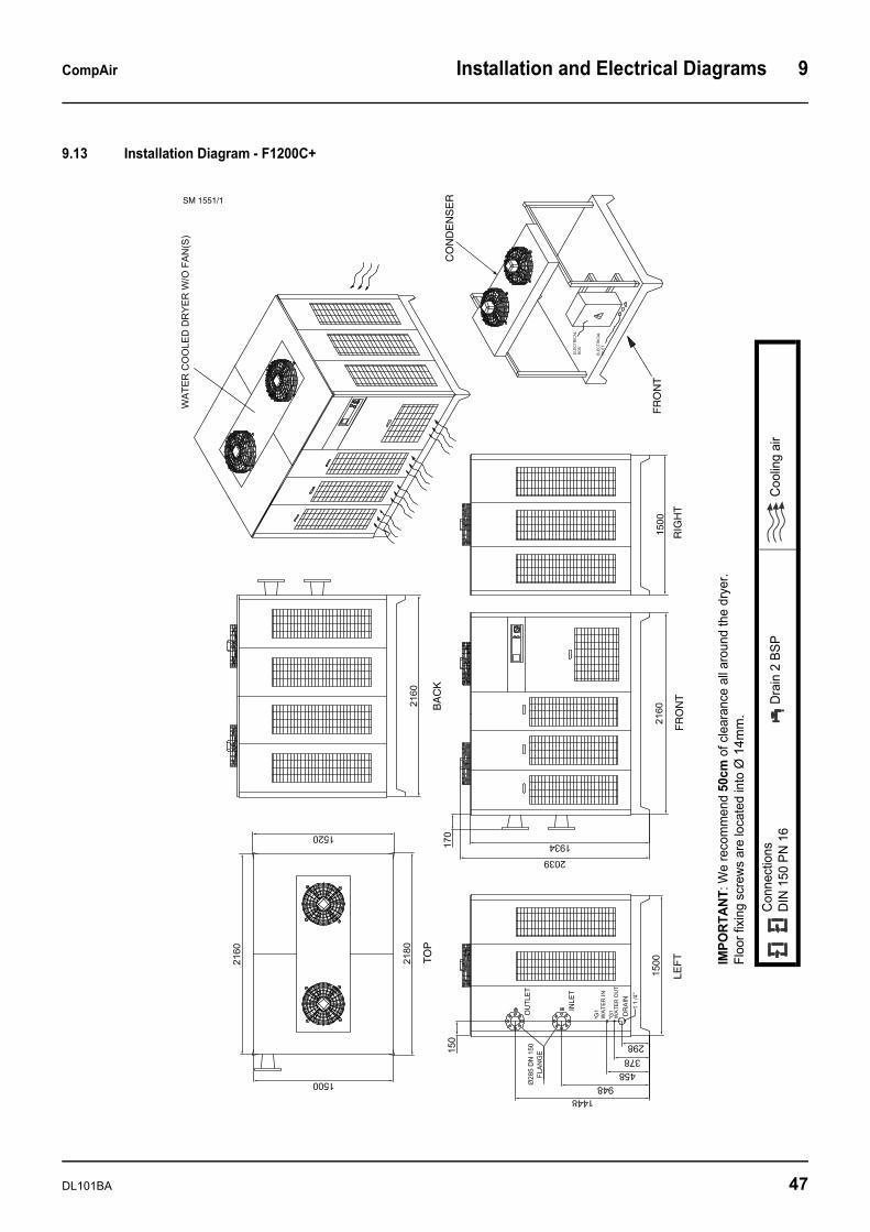
CompAir Installation and Electrical Diagrams 9
9.13 Installation Diagram - F1200C+
TO
PB
AC
K
OU
TLE
T
INLE
T
LEF
T
FR
ON
T
FR
ON
TR
IGH
T
CO
ND
EN
SE
R
*
SM 1551/1
IMPO
RTAN
T: W
e re
com
men
d 50
cm o
f cle
aran
ce a
ll ar
ound
the
drye
r. Fl
oor f
ixin
g sc
rew
s ar
e lo
cate
d in
to Ø
14m
m.
Con
nect
ions
DIN
150
PN
16
Dra
in 2
BSP
Coo
ling
air
DL101BA 47
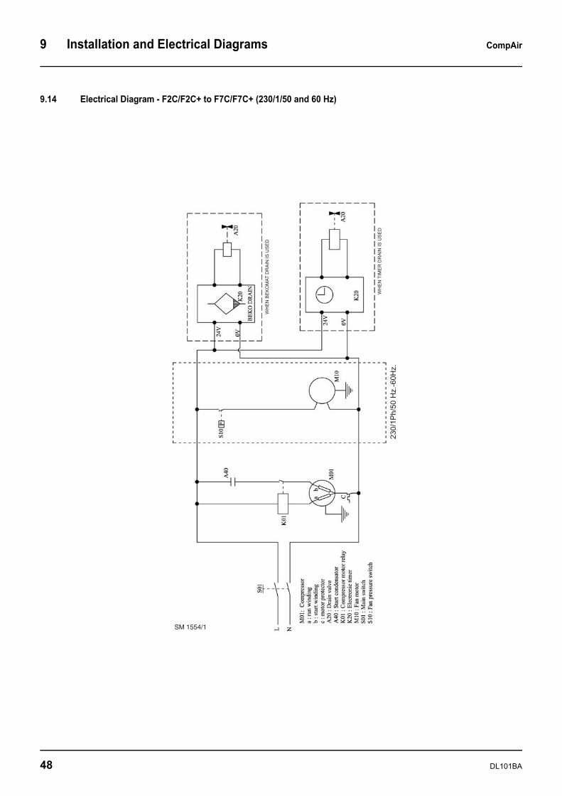
9 Installation and Electrical Diagrams CompAir
9.14 Electrical Diagram - F2C/F2C+ to F7C/F7C+ (230/1/50 and 60 Hz)
SM 1554/1
48 DL101BA
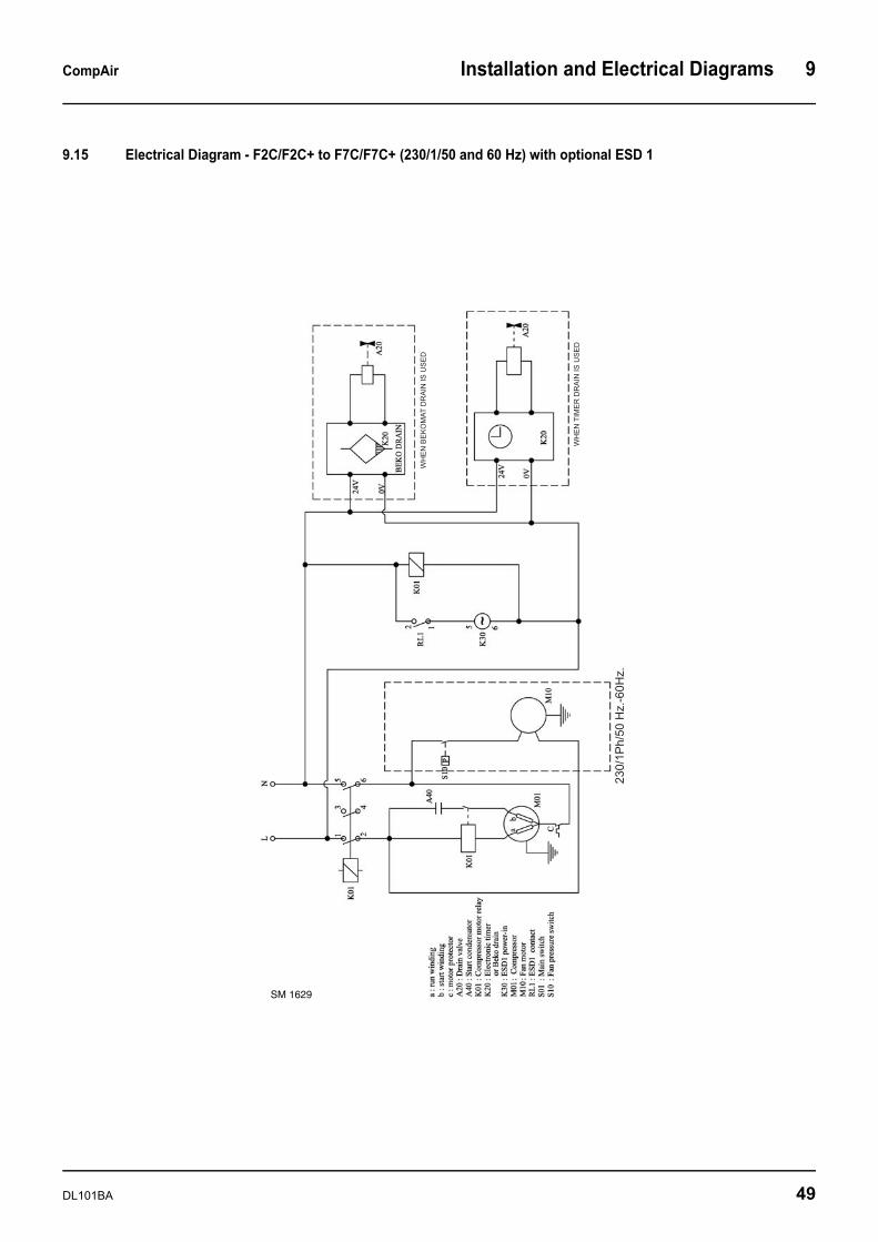
CompAir Installation and Electrical Diagrams 9
9.15 Electrical Diagram - F2C/F2C+ to F7C/F7C+ (230/1/50 and 60 Hz) with optional ESD 1
SM 1629
DL101BA 49

9 Installation and Electrical Diagrams CompAir
9.16 Electrical Diagram - F11C/F11C+ to F45C/F45C+ (230/1/50 and 60Hz)
SM 1555/1
50 DL101BA
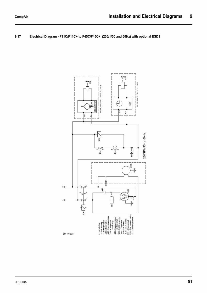
CompAir Installation and Electrical Diagrams 9
9.17 Electrical Diagram - F11C/F11C+ to F45C/F45C+ (230/1/50 and 60Hz) with optional ESD1
SM 1630/1
230/
1Ph/
50H
z.-6
0Hz.
DL101BA 51
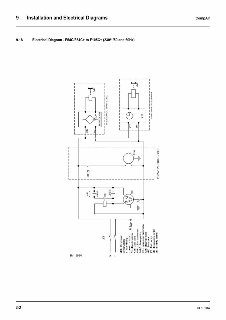
9 Installation and Electrical Diagrams CompAir
9.18 Electrical Diagram - F54C/F54C+ to F105C+ (230/1/50 and 60Hz)
SM 1556/1
52 DL101BA
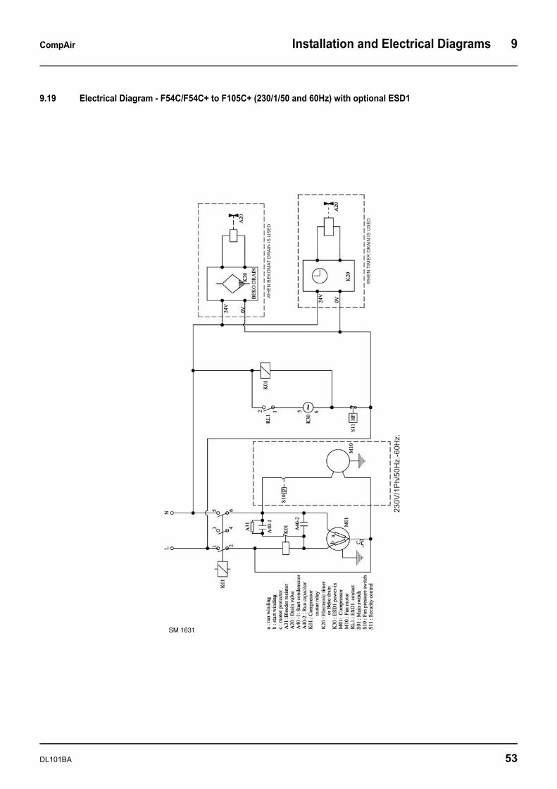
CompAir Installation and Electrical Diagrams 9
9.19 Electrical Diagram - F54C/F54C+ to F105C+ (230/1/50 and 60Hz) with optional ESD1
SM 1631
DL101BA 53
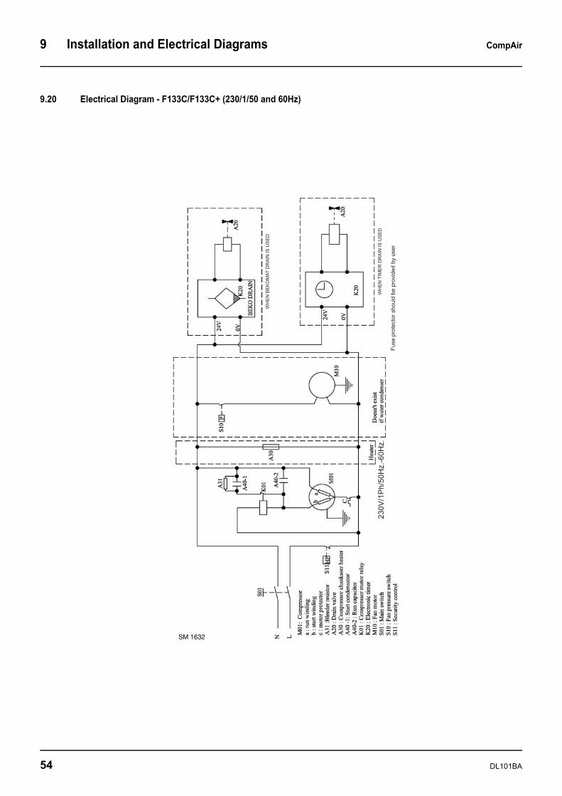
9 Installation and Electrical Diagrams CompAir
9.20 Electrical Diagram - F133C/F133C+ (230/1/50 and 60Hz)
SM 1632
54 DL101BA
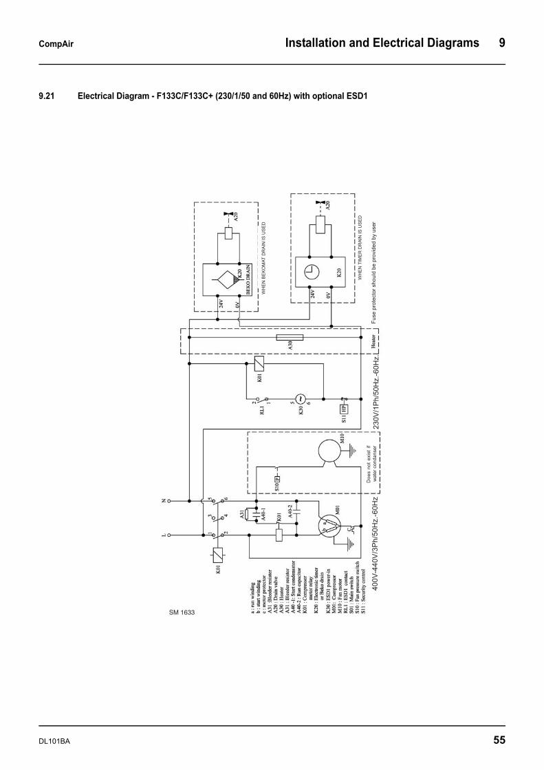
CompAir Installation and Electrical Diagrams 9
9.21 Electrical Diagram - F133C/F133C+ (230/1/50 and 60Hz) with optional ESD1
SM 1633
DL101BA 55
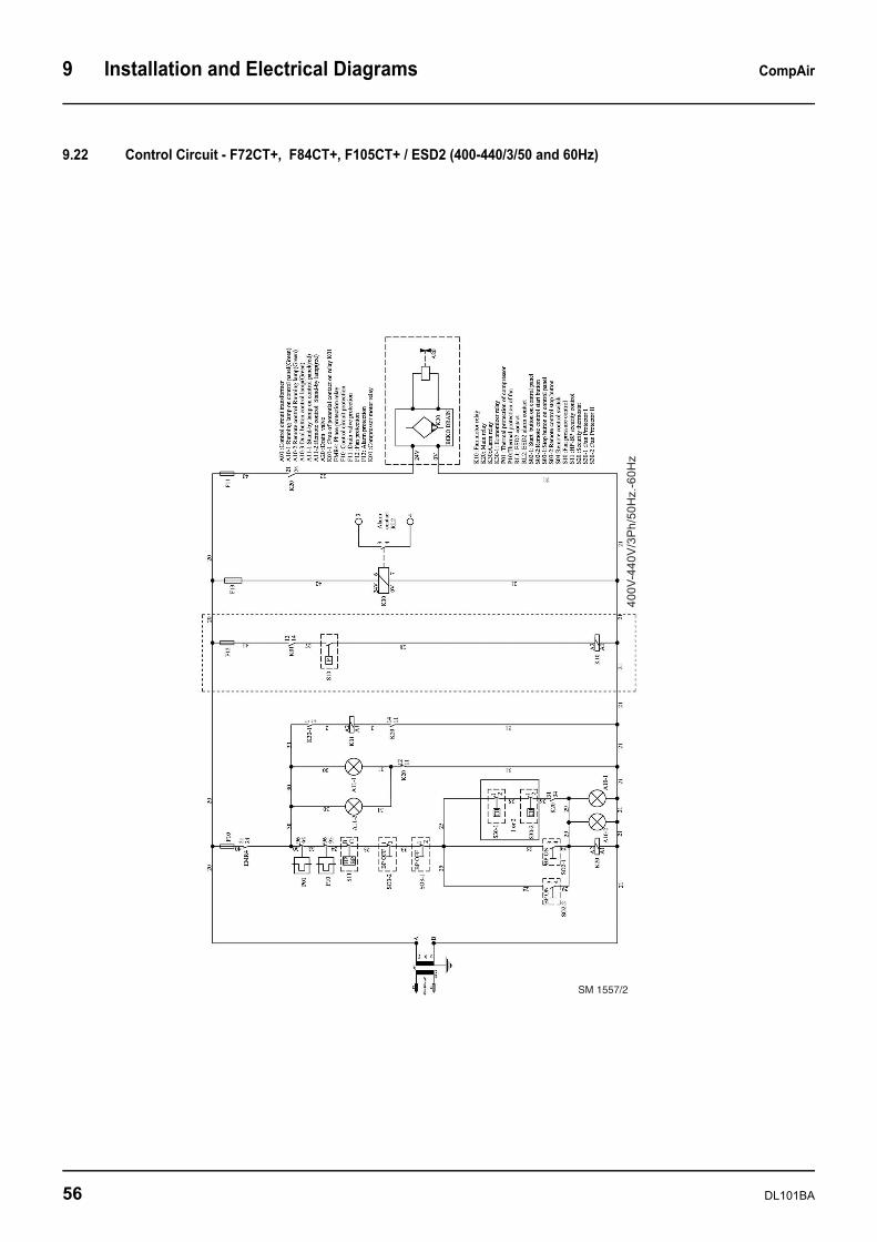
9 Installation and Electrical Diagrams CompAir
9.22 Control Circuit - F72CT+, F84CT+, F105CT+ / ESD2 (400-440/3/50 and 60Hz)
SM 1557/2
56 DL101BA

CompAir Installation and Electrical Diagrams 9
9.23 Power Circuit - F72CT+, F84CT+, F105CT+ / ESD2 (400-440/3/50 and 60Hz)
SM 1558/1
DL101BA 57
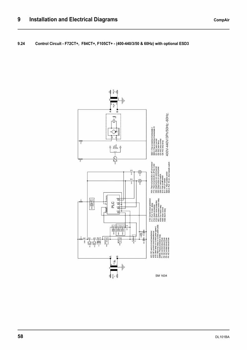
9 Installation and Electrical Diagrams CompAir
9.24 Control Circuit - F72CT+, F84CT+, F105CT+ - (400-440/3/50 & 60Hz) with optional ESD3
SM 1634
58 DL101BA
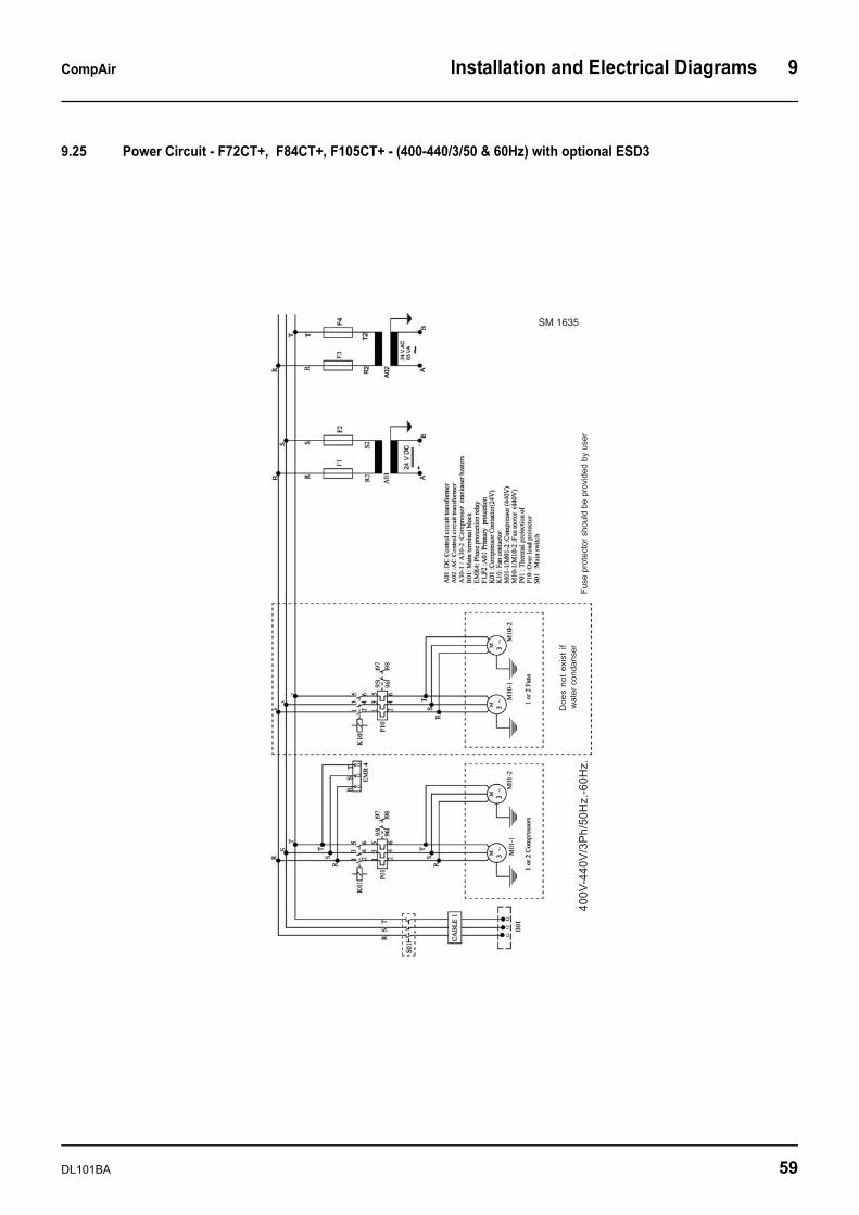
CompAir Installation and Electrical Diagrams 9
9.25 Power Circuit - F72CT+, F84CT+, F105CT+ - (400-440/3/50 & 60Hz) with optional ESD3
SM 1635
DL101BA 59
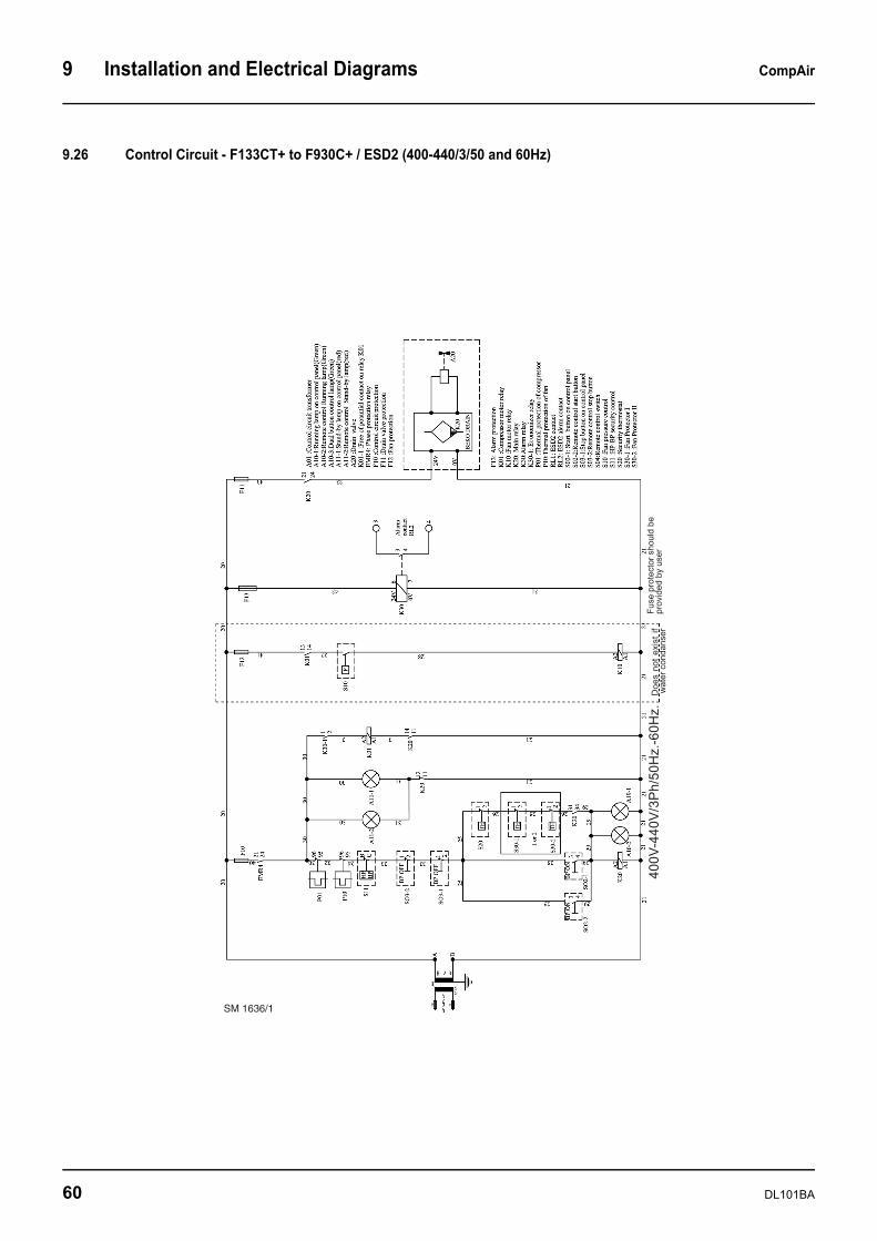
9 Installation and Electrical Diagrams CompAir
9.26 Control Circuit - F133CT+ to F930C+ / ESD2 (400-440/3/50 and 60Hz)
SM 1636/1
60 DL101BA
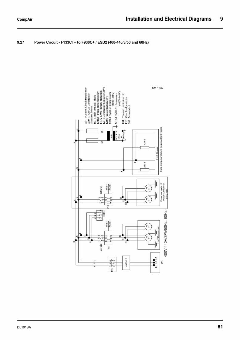
CompAir Installation and Electrical Diagrams 9
9.27 Power Circuit - F133CT+ to F930C+ / ESD2 (400-440/3/50 and 60Hz)
SM 1637
DL101BA 61
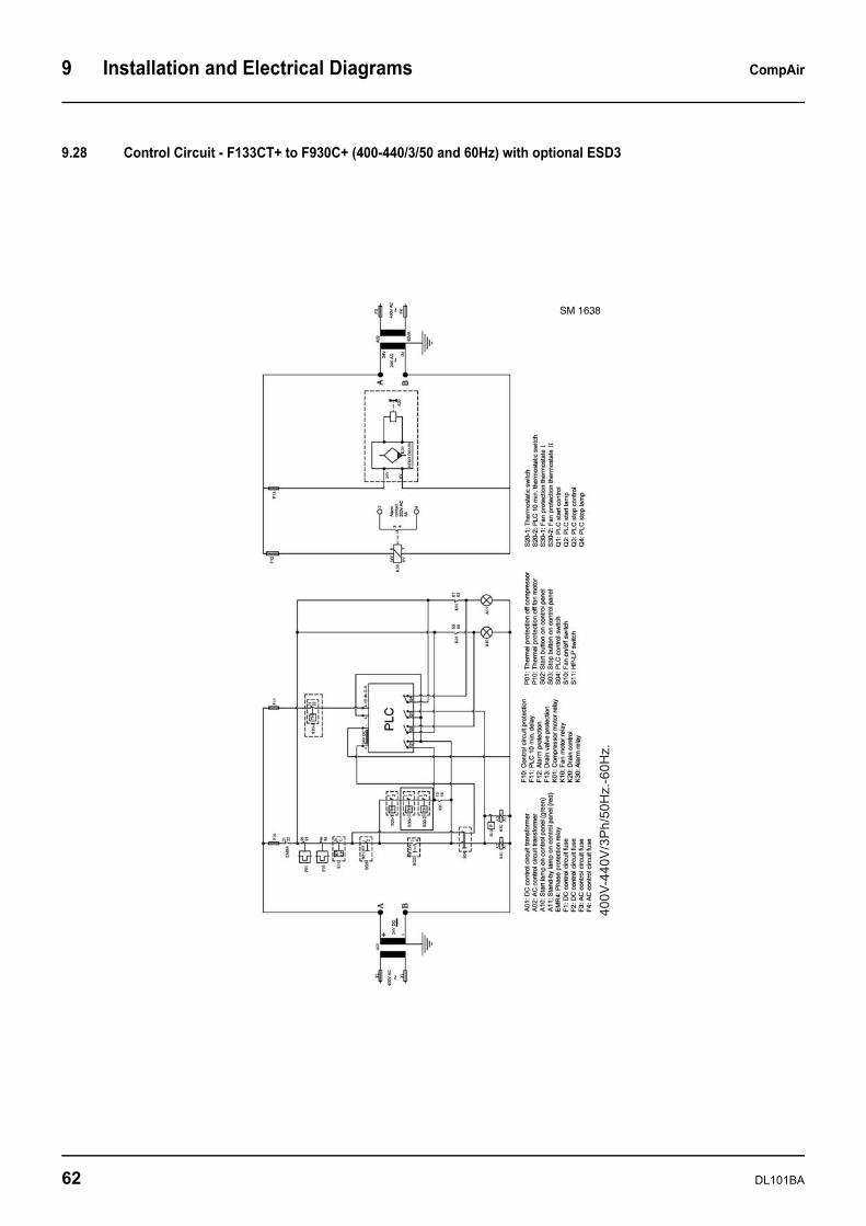
9 Installation and Electrical Diagrams CompAir
9.28 Control Circuit - F133CT+ to F930C+ (400-440/3/50 and 60Hz) with optional ESD3
SM 1638
62 DL101BA
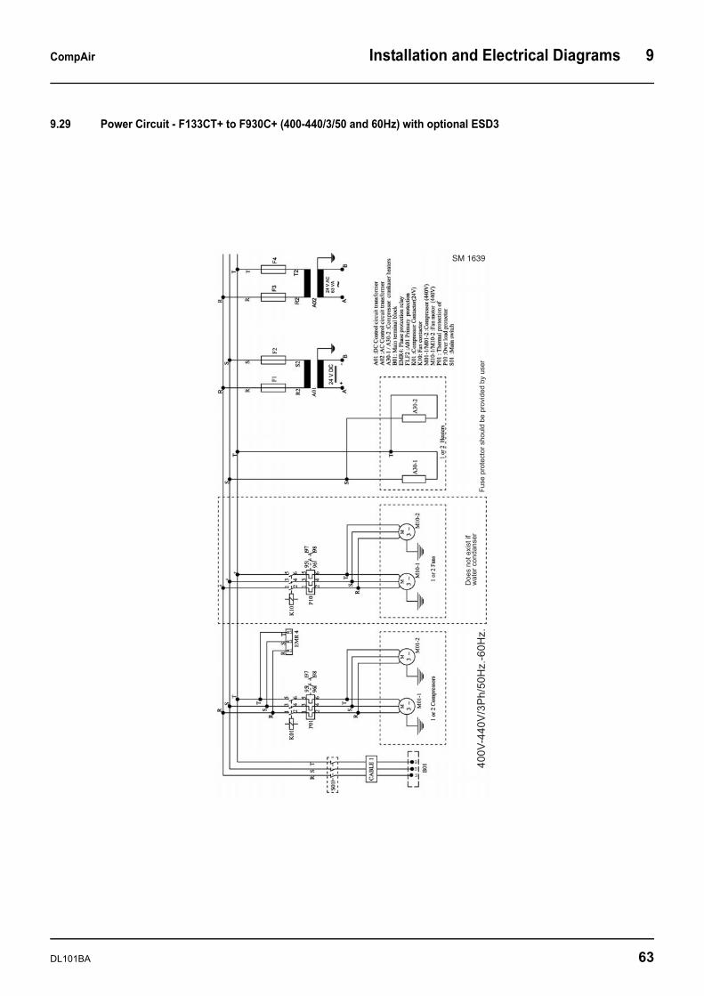
CompAir Installation and Electrical Diagrams 9
9.29 Power Circuit - F133CT+ to F930C+ (400-440/3/50 and 60Hz) with optional ESD3
SM 1639
DL101BA 63
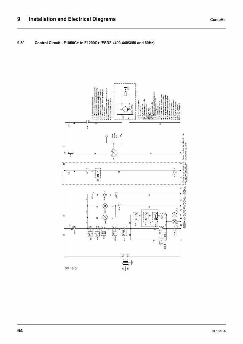
9 Installation and Electrical Diagrams CompAir
9.30 Control Circuit - F1050C+ to F1200C+ /ESD2 (400-440/3/50 and 60Hz)
SM 1640/1
64 DL101BA
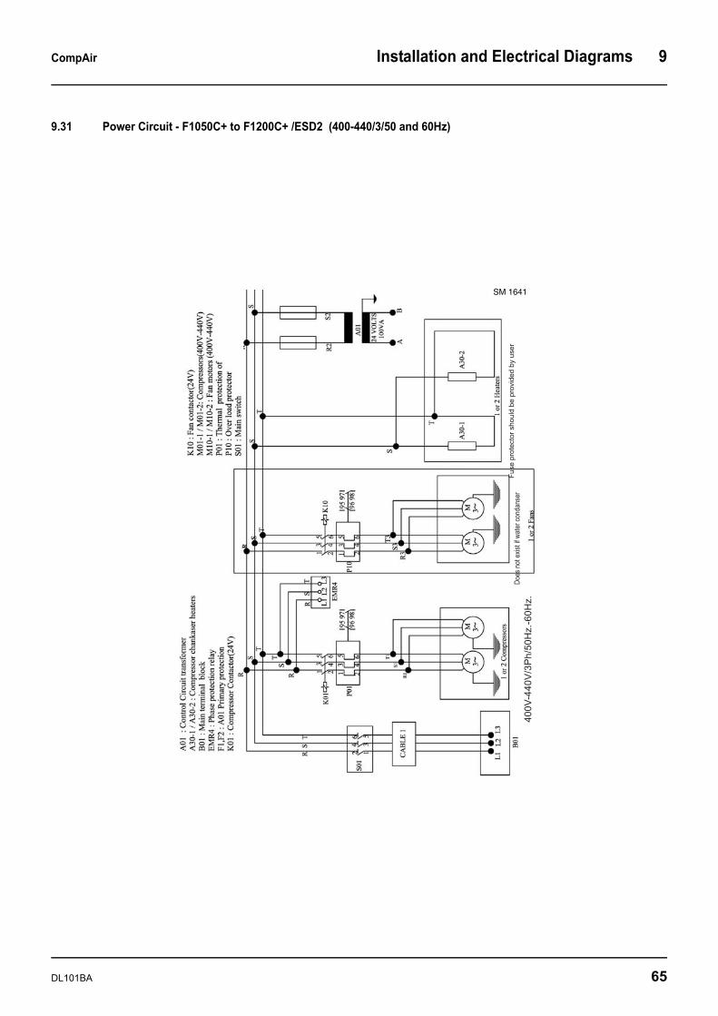
CompAir Installation and Electrical Diagrams 9
9.31 Power Circuit - F1050C+ to F1200C+ /ESD2 (400-440/3/50 and 60Hz)
SM 1641
DL101BA 65
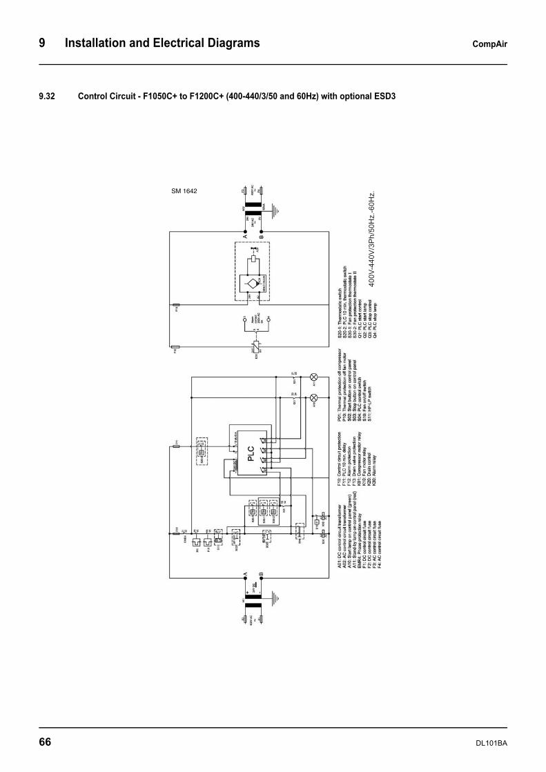
9 Installation and Electrical Diagrams CompAir
9.32 Control Circuit - F1050C+ to F1200C+ (400-440/3/50 and 60Hz) with optional ESD3
SM 1642
66 DL101BA
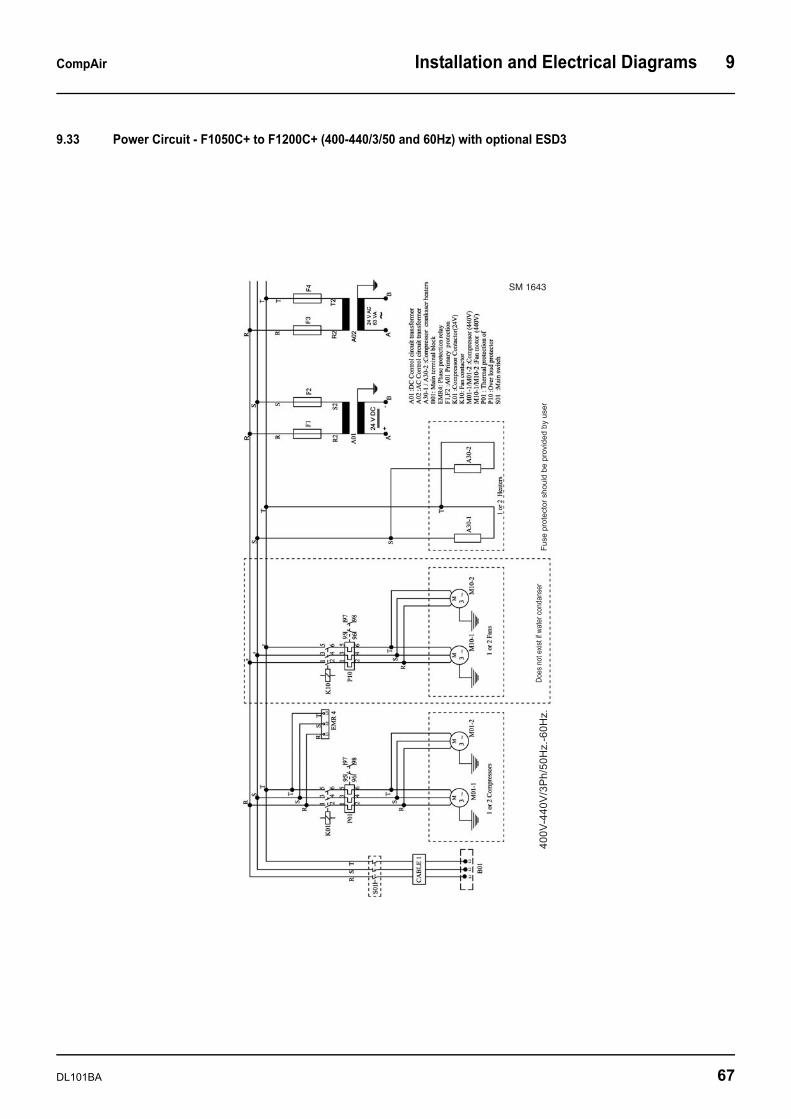
CompAir Installation and Electrical Diagrams 9
9.33 Power Circuit - F1050C+ to F1200C+ (400-440/3/50 and 60Hz) with optional ESD3
SM 1643
DL101BA 67
9 Installation and Electrical Diagrams CompAir
68 DL101BA
Gardner Denver Ltd. CompAir Head Office
& Industrial Vane & Portable CompressorsClaybrook Drive
Washford Industrial Estate Redditch Worcestershire
B98 0DS
Tel: ++44 (0) 1527 838 200
www.compair.comemail: [email protected]
CompAir DrucklufttechnikZweigniederlassung der Gardner Denver Deutschland GmbH
Argenthaler Straße 11 55469 Simmern/Hunsrück
Deutschland
Tel: ++49 6761 832-0
www.compair.de email: [email protected]


