CHAPTER 1-1 Cisco ASA 5500 Series Hardware Installation Guide 78-17989-01 1 Maintenance and Upgrade Procedures This chapter describes how to, remove and replace the chassis cover, the power supply, and the CompactFlash. This chapter includes the following sections: • Removing and Replacing the Chassis Cover, page 1-1 • Working in an ESD Environment, page 1-3 • Removing and Replacing a Lithium Battery in the SSM, page 1-4 • Removing and Replacing the Power Supply, page 1-4 • Installing the DC Model, page 1-7 • Removing and Replacing the CompactFlash, page 1-10 • Installing and Replacing the 4GE SSM, page 1-14 • Installing and Replacing the Intelligent SSM, page 1-20 • Replacing Memory in the Adaptive Security Appliance, page 1-23 Removing and Replacing the Chassis Cover This section describes how to remove and replace the chassis cover. This section includes the following topics: • Removing the Chassis Cover, page 1-1 • Replacing the Chassis Cover, page 1-2s Removing the Chassis Cover To remove the chassis cover, perform the following steps: Note Removing the chassis cover does not affect Cisco warranty. Upgrading the adaptive security appliance does not require any special tools and does not create any radio frequency leaks. Step 1 Read the Regulatory Compliance and Safety Information for the Cisco ASA 5500 Series document. Step 2 Power off the adaptive security appliance. Once the upgrade is complete, you can safely power on the chassis.
Transcript
C H A P T E R
1-1Cisco ASA 5500 Series Hardware Installation Guide
78-17989-01
1Maintenance and Upgrade Procedures
This chapter describes how to, remove and replace the chassis cover, the power supply, and the CompactFlash. This chapter includes the following sections:
• Removing and Replacing the Chassis Cover, page 1-1
• Working in an ESD Environment, page 1-3
• Removing and Replacing a Lithium Battery in the SSM, page 1-4
• Removing and Replacing the Power Supply, page 1-4
• Installing the DC Model, page 1-7
• Removing and Replacing the CompactFlash, page 1-10
• Installing and Replacing the 4GE SSM, page 1-14
• Installing and Replacing the Intelligent SSM, page 1-20
• Replacing Memory in the Adaptive Security Appliance, page 1-23
Removing and Replacing the Chassis CoverThis section describes how to remove and replace the chassis cover. This section includes the following topics:
• Removing the Chassis Cover, page 1-1
• Replacing the Chassis Cover, page 1-2s
Removing the Chassis Cover To remove the chassis cover, perform the following steps:
Note Removing the chassis cover does not affect Cisco warranty. Upgrading the adaptive security appliance does not require any special tools and does not create any radio frequency leaks.
Step 1 Read the Regulatory Compliance and Safety Information for the Cisco ASA 5500 Series document.
Step 2 Power off the adaptive security appliance. Once the upgrade is complete, you can safely power on the chassis.
1-2Cisco ASA 5500 Series Hardware Installation Guide
78-17989-01
Chapter 1 Maintenance and Upgrade ProceduresRemoving and Replacing the Chassis Cover
Warning Before working on a system that has an On/Off switch, turn OFF the power and unplug the power cord. Statement 1
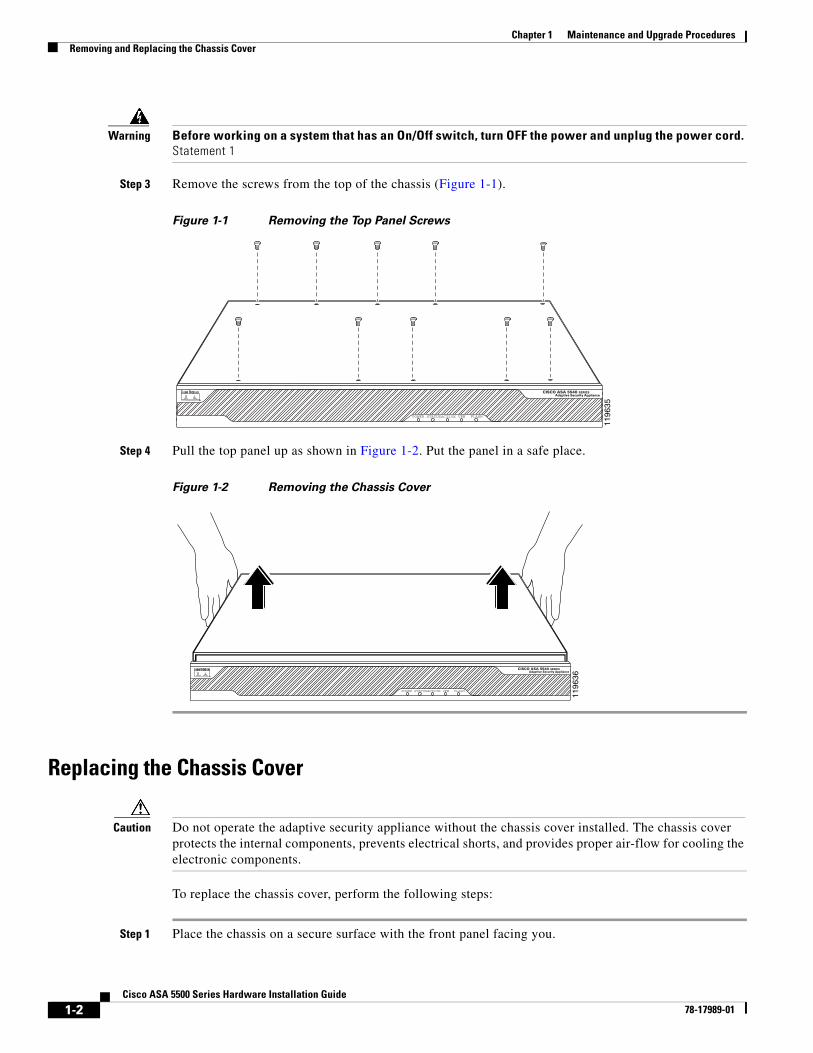
Step 3 Remove the screws from the top of the chassis (Figure 1-1).
Figure 1-1 Removing the Top Panel Screws
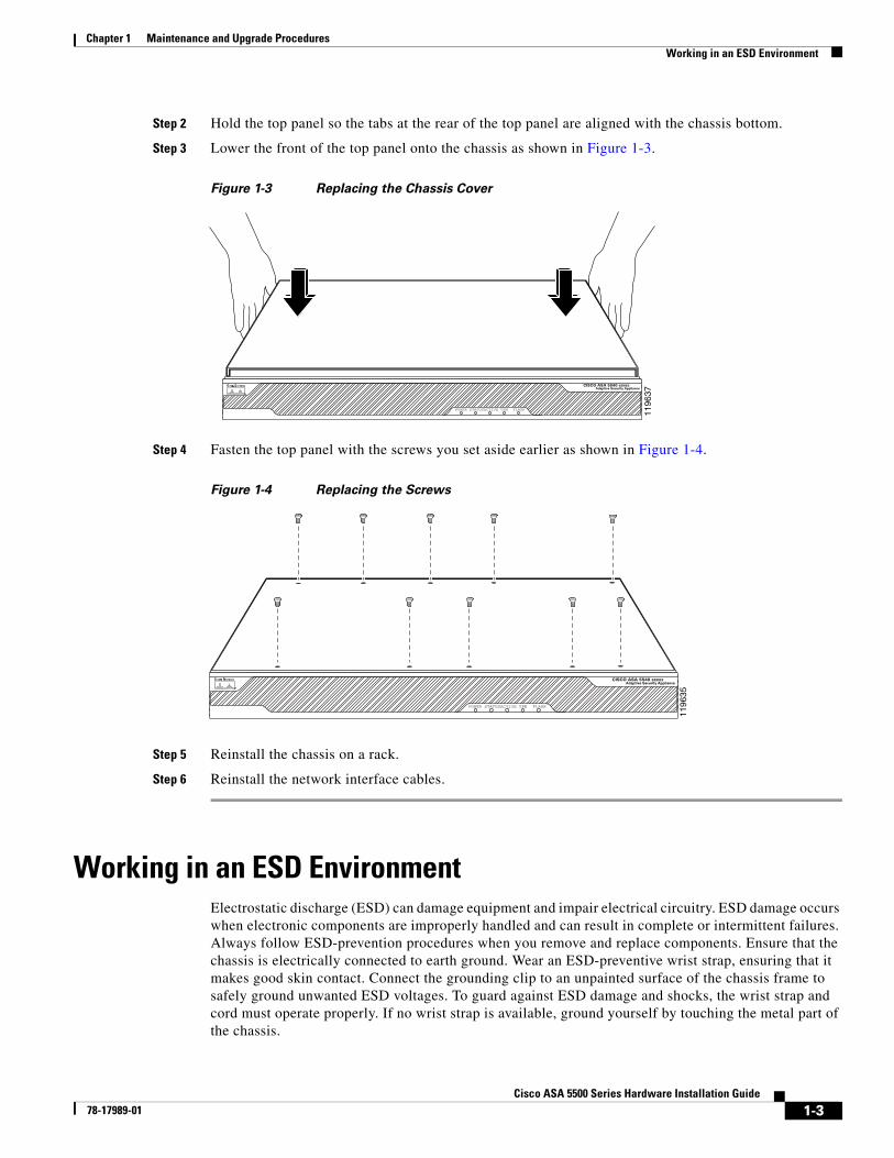
Step 4 Pull the top panel up as shown in Figure 1-2. Put the panel in a safe place.
Figure 1-2 Removing the Chassis Cover
Replacing the Chassis Cover
Caution Do not operate the adaptive security appliance without the chassis cover installed. The chassis cover protects the internal components, prevents electrical shorts, and provides proper air-flow for cooling the electronic components.
To replace the chassis cover, perform the following steps:
Step 1 Place the chassis on a secure surface with the front panel facing you.
1196
35
POWER STATUS FLASHACTIVE VPN
CISCO ASA 5540 SERIESAdaptive Security Appliance
1196
36
POWER STATUS FLASHACTIVE VPN
CISCO ASA 5540 SERIESAdaptive Security Appliance
1-3Cisco ASA 5500 Series Hardware Installation Guide
78-17989-01
Chapter 1 Maintenance and Upgrade ProceduresWorking in an ESD Environment
Step 2 Hold the top panel so the tabs at the rear of the top panel are aligned with the chassis bottom.
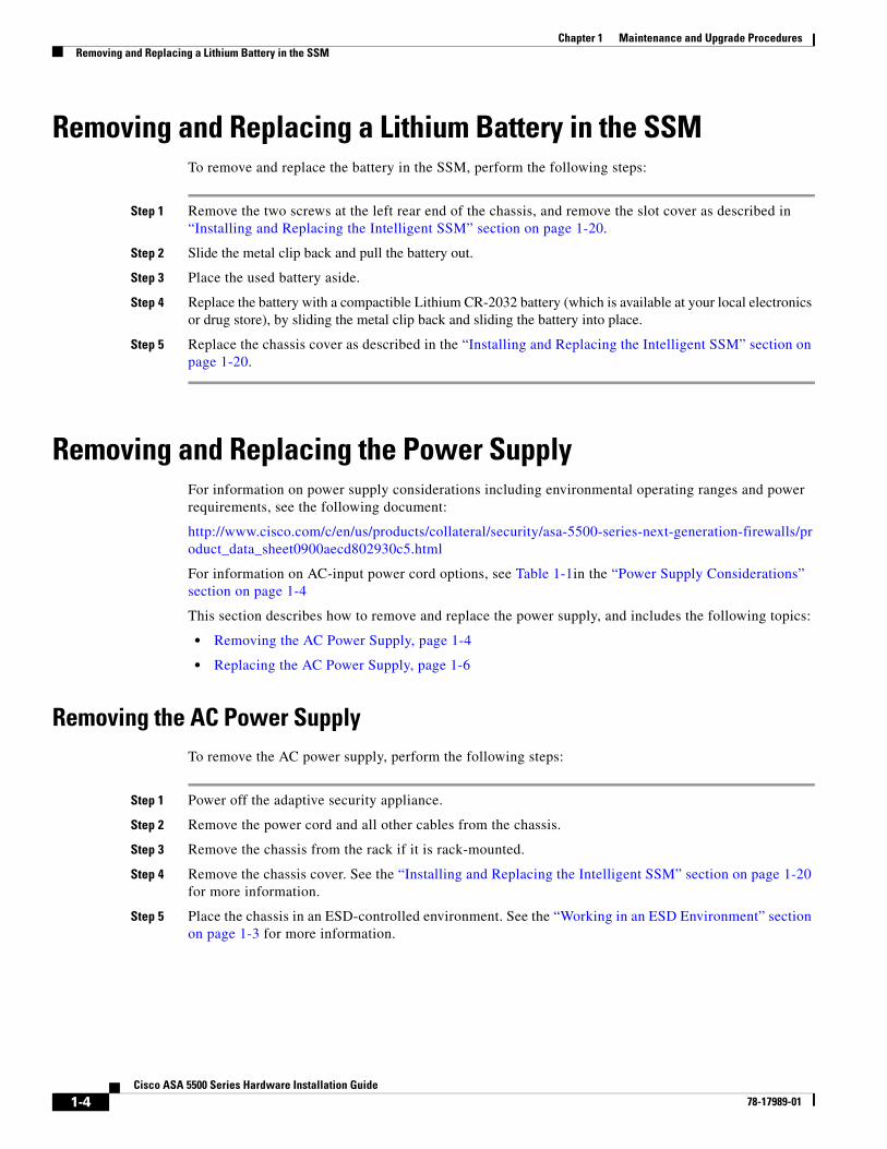
Step 3 Lower the front of the top panel onto the chassis as shown in Figure 1-3.
Figure 1-3 Replacing the Chassis Cover
Step 4 Fasten the top panel with the screws you set aside earlier as shown in Figure 1-4.
Figure 1-4 Replacing the Screws
Step 5 Reinstall the chassis on a rack.
Step 6 Reinstall the network interface cables.
Working in an ESD EnvironmentElectrostatic discharge (ESD) can damage equipment and impair electrical circuitry. ESD damage occurs when electronic components are improperly handled and can result in complete or intermittent failures. Always follow ESD-prevention procedures when you remove and replace components. Ensure that the chassis is electrically connected to earth ground. Wear an ESD-preventive wrist strap, ensuring that it makes good skin contact. Connect the grounding clip to an unpainted surface of the chassis frame to safely ground unwanted ESD voltages. To guard against ESD damage and shocks, the wrist strap and cord must operate properly. If no wrist strap is available, ground yourself by touching the metal part of the chassis.
1196
37
POWER STATUS FLASHACTIVE VPN
CISCO ASA 5540 SERIESAdaptive Security Appliance
1196
35
POWER STATUS FLASHACTIVE VPN
CISCO ASA 5540 SERIESAdaptive Security Appliance
1-4Cisco ASA 5500 Series Hardware Installation Guide
78-17989-01
Chapter 1 Maintenance and Upgrade ProceduresRemoving and Replacing a Lithium Battery in the SSM
Removing and Replacing a Lithium Battery in the SSMTo remove and replace the battery in the SSM, perform the following steps:
Step 1 Remove the two screws at the left rear end of the chassis, and remove the slot cover as described in “Installing and Replacing the Intelligent SSM” section on page 1-20.
Step 2 Slide the metal clip back and pull the battery out.
Step 3 Place the used battery aside.
Step 4 Replace the battery with a compactible Lithium CR-2032 battery (which is available at your local electronics or drug store), by sliding the metal clip back and sliding the battery into place.
Step 5 Replace the chassis cover as described in the “Installing and Replacing the Intelligent SSM” section on page 1-20.
Removing and Replacing the Power SupplyFor information on power supply considerations including environmental operating ranges and power requirements, see the following document:
1-5Cisco ASA 5500 Series Hardware Installation Guide
78-17989-01
Chapter 1 Maintenance and Upgrade ProceduresRemoving and Replacing the Power Supply
Step 6 Lift the rear of the chassis from the surface and unscrew both the screws that secures the power supply to the chassis, as shown in Figure 1-5.
Figure 1-5 Removing the Power Supply Screws
Step 7 Locate the power connector on the system board.
Step 8 Unlatch the plug, then grasp the sides of the power connector and pull upward while rocking the connector from side to side. Disconnect the power connector from the system board as shown in Figure 1-6.
Figure 1-6 Disconnecting the Power Connector
1 Chassis bottom
1195
81
POW
ER
FLASH
STA
TUS
FLASH
ACTI
VE
VPN
1
1 AC power supply 2 Power connector
1196
39
1
2
1-6Cisco ASA 5500 Series Hardware Installation Guide
78-17989-01
Chapter 1 Maintenance and Upgrade ProceduresRemoving and Replacing the Power Supply
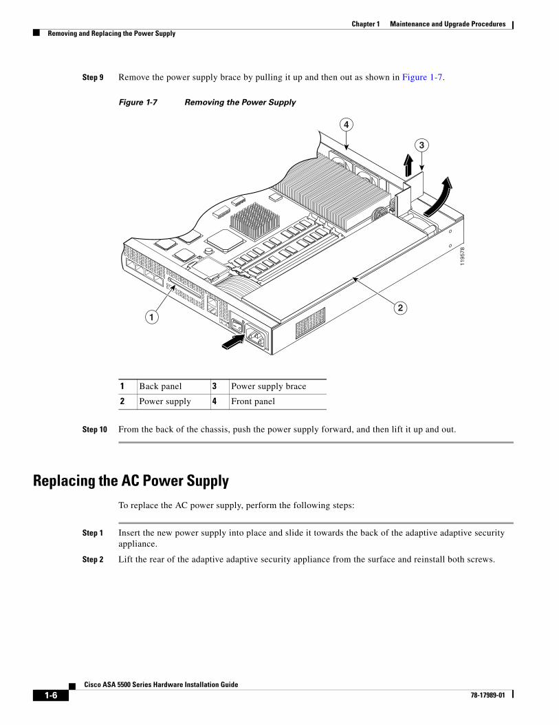
Step 9 Remove the power supply brace by pulling it up and then out as shown in Figure 1-7.
Figure 1-7 Removing the Power Supply
Step 10 From the back of the chassis, push the power supply forward, and then lift it up and out.
Replacing the AC Power SupplyTo replace the AC power supply, perform the following steps:
Step 1 Insert the new power supply into place and slide it towards the back of the adaptive adaptive security appliance.
Step 2 Lift the rear of the adaptive adaptive security appliance from the surface and reinstall both screws.
1 Back panel 3 Power supply brace
2 Power supply 4 Front panel
1195
78
3
12
4
1-7Cisco ASA 5500 Series Hardware Installation Guide
78-17989-01
Chapter 1 Maintenance and Upgrade ProceduresInstalling the DC Model
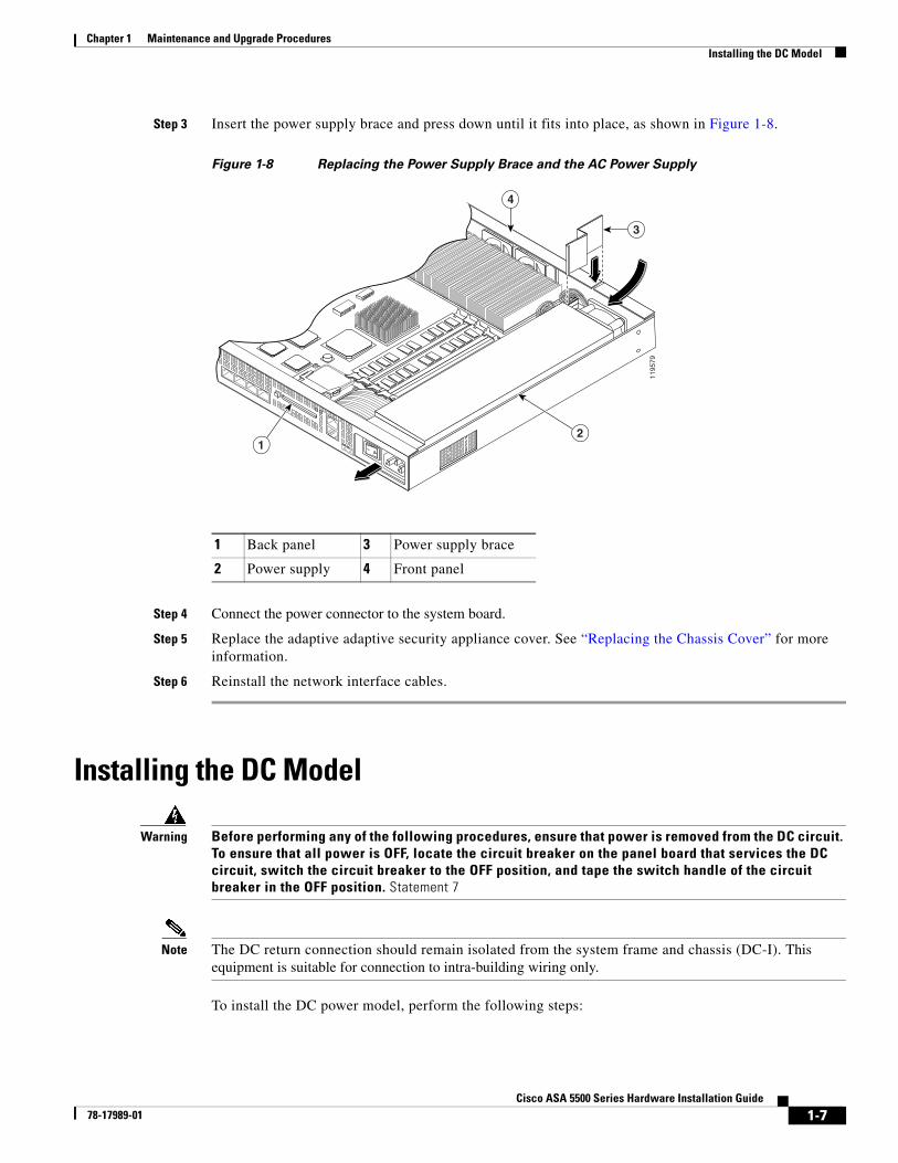
Step 3 Insert the power supply brace and press down until it fits into place, as shown in Figure 1-8.
Figure 1-8 Replacing the Power Supply Brace and the AC Power Supply
Step 4 Connect the power connector to the system board.
Step 5 Replace the adaptive adaptive security appliance cover. See “Replacing the Chassis Cover” for more information.
Step 6 Reinstall the network interface cables.
Installing the DC Model
Warning Before performing any of the following procedures, ensure that power is removed from the DC circuit. To ensure that all power is OFF, locate the circuit breaker on the panel board that services the DC circuit, switch the circuit breaker to the OFF position, and tape the switch handle of the circuit breaker in the OFF position. Statement 7
Note The DC return connection should remain isolated from the system frame and chassis (DC-I). This equipment is suitable for connection to intra-building wiring only.
To install the DC power model, perform the following steps:
1 Back panel 3 Power supply brace
2 Power supply 4 Front panel
1195
79
3
12
4
1-8Cisco ASA 5500 Series Hardware Installation Guide
78-17989-01
Chapter 1 Maintenance and Upgrade ProceduresInstalling the DC Model
Step 1 Read the Regulatory Compliance and Safety Information for the Cisco ASA 5500 Series document.
Step 2 Terminate the DC input wiring on a DC source capable of supplying at least 15 amps. A 15-amp circuit breaker is required at the 48 VDC facility power source. An easily accessible disconnect device should be incorporated into the facility wiring.
Step 3 Locate the DC-input terminal box, see Figure 1-9.
Figure 1-9 DC-Input Terminal Box
Step 4 Power off the adaptive security appliance. Ensure that power is removed from the DC circuit. To ensure that all power is OFF, locate the circuit breaker on the panel board that services the DC circuit, switch the circuit breaker to the OFF position, and tape the switch handle of the circuit breaker in the OFF position.
Step 5 Remove the DC power supply plastic shield.
Step 6 The adaptive security appliance is equipped with two grounding holes at the side of the chassis, which you can use to connect a two-hole grounding lug to the adaptive security appliance. Use 8-32 screws to connect a copper standard barrel grounding lug to the holes. The adaptive security appliance requires a lug where the distance between the center of each hole is 0.56 inches. A lug is not supplied with the adaptive security appliance.
Step 7 Strip the ends of the wires for insertion into the power connect lugs on the adaptive security appliance.
1 Negative 3 Ground
2 Positive 4 On/Off switch
1196
40
+ –
1
4
32
1-9Cisco ASA 5500 Series Hardware Installation Guide
78-17989-01
Chapter 1 Maintenance and Upgrade ProceduresInstalling the DC Model
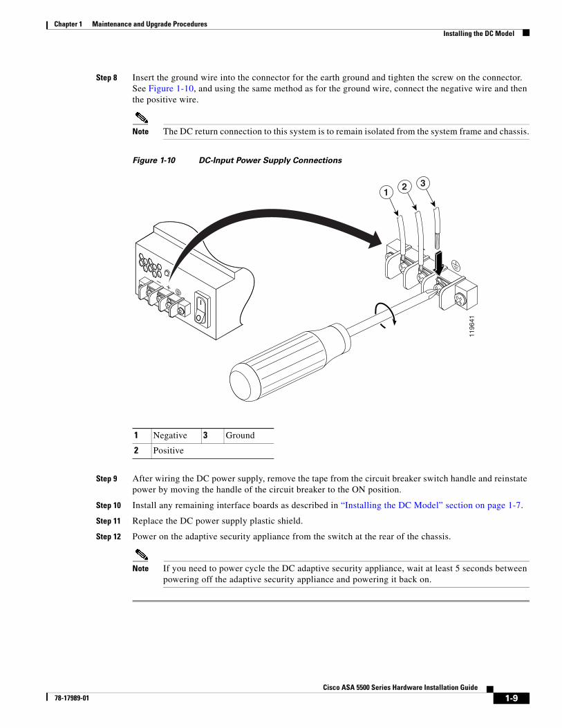
Step 8 Insert the ground wire into the connector for the earth ground and tighten the screw on the connector. See Figure 1-10, and using the same method as for the ground wire, connect the negative wire and then the positive wire.
Note The DC return connection to this system is to remain isolated from the system frame and chassis.
Figure 1-10 DC-Input Power Supply Connections
Step 9 After wiring the DC power supply, remove the tape from the circuit breaker switch handle and reinstate power by moving the handle of the circuit breaker to the ON position.
Step 10 Install any remaining interface boards as described in “Installing the DC Model” section on page 1-7.
Step 11 Replace the DC power supply plastic shield.
Step 12 Power on the adaptive security appliance from the switch at the rear of the chassis.
Note If you need to power cycle the DC adaptive security appliance, wait at least 5 seconds between powering off the adaptive security appliance and powering it back on.
1 Negative 3 Ground
2 Positive
1196
41
+ –
+ –
12 3
1-10Cisco ASA 5500 Series Hardware Installation Guide
78-17989-01
Chapter 1 Maintenance and Upgrade ProceduresRemoving and Replacing the CompactFlash
Removing and Replacing the CompactFlash The adaptive security appliance has two types of CompactFlash: the system CompactFlash (internal) and the user CompactFlash (external). This section includes the following topics:
• Removing and Installing the System CompactFlash, page 1-10
• Removing and Installing the User CompactFlash, page 1-12
Removing and Installing the System CompactFlash To remove and install the system CompactFlash, perform the following steps:
Step 1 Power off the adaptive security appliance.
Step 2 Remove the power cord and other cables from the adaptive security appliance.
Step 3 Remove the adaptive security appliance from the rack if it is rack-mounted.
Step 4 Place the adaptive security appliance in an ESD-controlled environment.
Step 5 Remove the adaptive security appliance cover.
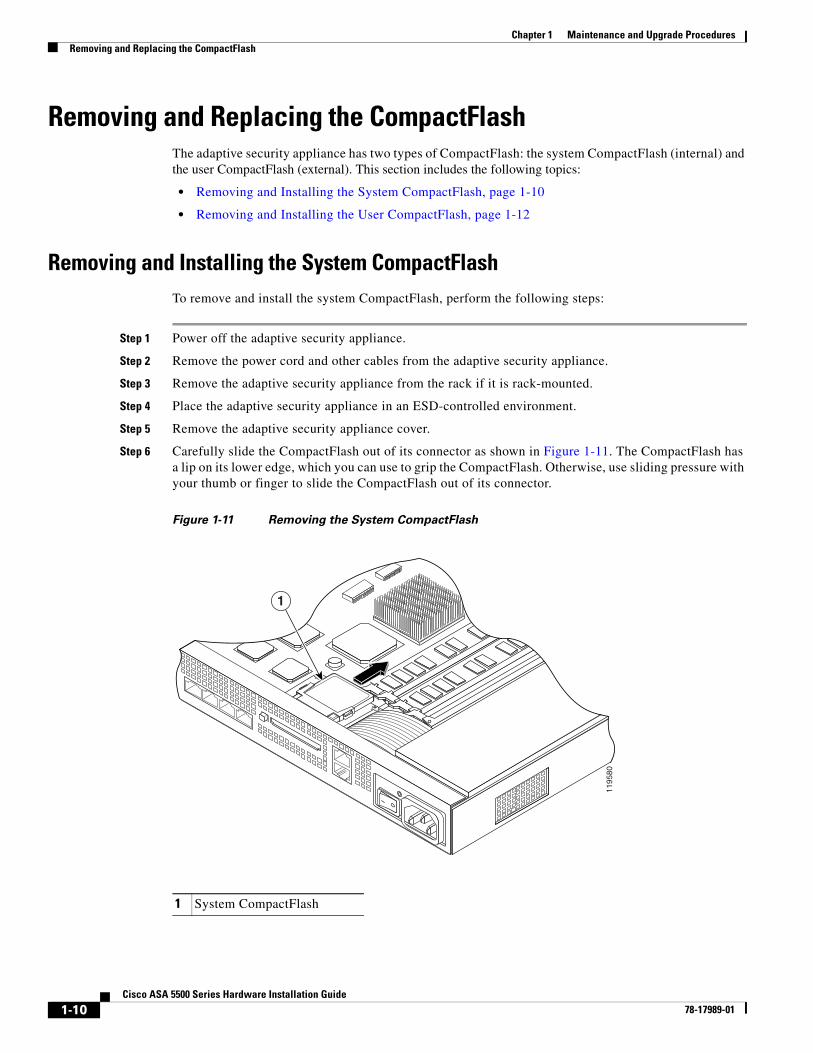
Step 6 Carefully slide the CompactFlash out of its connector as shown in Figure 1-11. The CompactFlash has a lip on its lower edge, which you can use to grip the CompactFlash. Otherwise, use sliding pressure with your thumb or finger to slide the CompactFlash out of its connector.
Figure 1-11 Removing the System CompactFlash
1 System CompactFlash
1195
801
1-11Cisco ASA 5500 Series Hardware Installation Guide
78-17989-01
Chapter 1 Maintenance and Upgrade ProceduresRemoving and Replacing the CompactFlash
Step 7 To install the system CompactFlash, align the new system CompactFlash with the connector on the riser card.
Step 8 Push the system CompactFlash inward until it is fully seated in the connector, see Figure 1-12.
Figure 1-12 Replacing the System CompactFlash
Step 9 Replace the adaptive security appliance cover.
Step 10 Reinstall the network interface cables.
1 System CompactFlash
1140
04
1
1-12Cisco ASA 5500 Series Hardware Installation Guide
78-17989-01
Chapter 1 Maintenance and Upgrade ProceduresRemoving and Replacing the CompactFlash
Removing and Installing the User CompactFlash To remove and install the user CompactFlash, perform the following steps:
Note There are two types of CompactFlash release buttons. The release buttons function differently. In this document we refer to them as Type A and Type B.
Step 1 Locate the user CompactFlash in its slot in the rear panel of the chassis. See Figure 1-13.
Figure 1-13 User CompactFlash and Release Button Location—Type A and B
Step 2 Press the release button, the release button in Type A will pop out towards you. See Figure 1-14.
In Type B pressing the release button once will eject the CompactFlash, the release button will be slightly extended. See Figure 1-15. If this is the case, skip Step 3 and go to Step 4.
Figure 1-14 Release Button Fully Extended—Type A
1 User CompactFlash in the slot 2 Release button extended
FLASH
CO
NS
OL
EA
UXPOWER
STATUS
FLASHVPNACTIVE
1
2
2461
94
1 User CompactFlash in the slot 2 Release button fully extended
FLASH
CO
NS
OL
EA
UXPOWER
STATUS
FLASHVPNACTIVE
1
2
2461
95
1-13Cisco ASA 5500 Series Hardware Installation Guide
78-17989-01
Chapter 1 Maintenance and Upgrade ProceduresRemoving and Replacing the CompactFlash
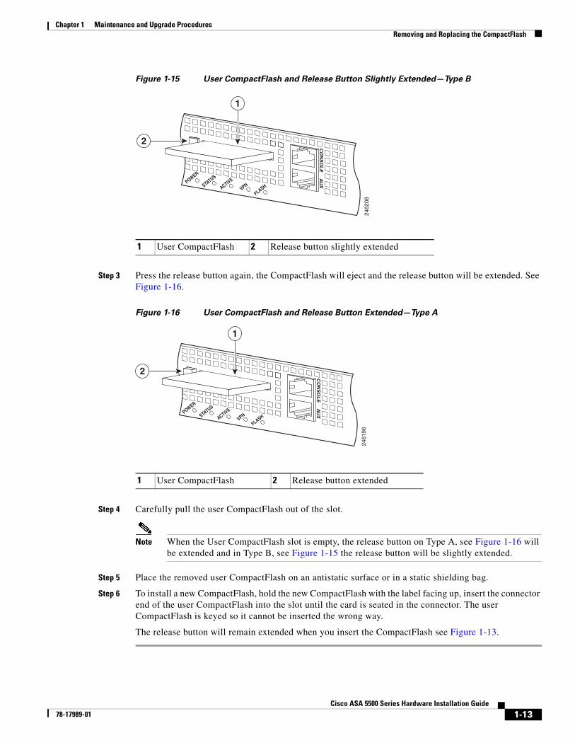
Figure 1-15 User CompactFlash and Release Button Slightly Extended—Type B
Step 3 Press the release button again, the CompactFlash will eject and the release button will be extended. See Figure 1-16.
Figure 1-16 User CompactFlash and Release Button Extended—Type A
Step 4 Carefully pull the user CompactFlash out of the slot.
Note When the User CompactFlash slot is empty, the release button on Type A, see Figure 1-16 will be extended and in Type B, see Figure 1-15 the release button will be slightly extended.
Step 5 Place the removed user CompactFlash on an antistatic surface or in a static shielding bag.
Step 6 To install a new CompactFlash, hold the new CompactFlash with the label facing up, insert the connector end of the user CompactFlash into the slot until the card is seated in the connector. The user CompactFlash is keyed so it cannot be inserted the wrong way.
The release button will remain extended when you insert the CompactFlash see Figure 1-13.
1 User CompactFlash 2 Release button slightly extended
FLASH
CO
NS
OL
EA
UXPOWER
STATUS
FLASHVPNACTIVE
1
2
2462
08
1 User CompactFlash 2 Release button extended
FLASH
CO
NS
OL
EA
UXPOWER
STATUS
FLASHVPNACTIVE
1
224
6196
1-14Cisco ASA 5500 Series Hardware Installation Guide
78-17989-01
Chapter 1 Maintenance and Upgrade ProceduresInstalling and Replacing the 4GE SSM
Installing and Replacing the 4GE SSMThe 4GE SSM has four 10/100/1000 Mbps, copper, RJ-45 ports and four optional 1000 Mbps, Small-Form-Factor Pluggable (SFP) fiber ports.
Note When using the 4GE SSM you can use the same numbered copper ports (RJ-45) and the SFP ports at the same time. Use the media-type command in interface configuration mode to set the media type to copper or fiber Gigabit Ethernet. For a complete description of the command syntax, see the Cisco ASA 5500 Series Command Reference.
This section describes how to install and replace the 4GE SSM in the adaptive security appliance, and includes the following topics:
• Overview, page 1-14
• Installing the 4GE SSM, page 1-15
• Replacing the 4GE SSM, page 1-16
• Installing and Removing the SFP Modules, page 1-16
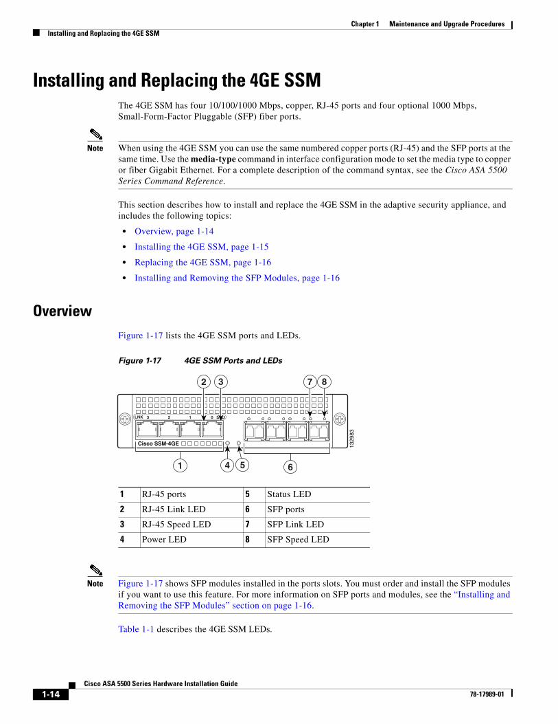
OverviewFigure 1-17 lists the 4GE SSM ports and LEDs.
Figure 1-17 4GE SSM Ports and LEDs
Note Figure 1-17 shows SFP modules installed in the ports slots. You must order and install the SFP modules if you want to use this feature. For more information on SFP ports and modules, see the “Installing and Removing the SFP Modules” section on page 1-16.
Table 1-1 describes the 4GE SSM LEDs.
1 RJ-45 ports 5 Status LED
2 RJ-45 Link LED 6 SFP ports
3 RJ-45 Speed LED 7 SFP Link LED
4 Power LED 8 SFP Speed LED
1329
83
41 65
7 8
LNK SPD0123
2 3
Cisco SSM-4GE
1-15Cisco ASA 5500 Series Hardware Installation Guide
78-17989-01
Chapter 1 Maintenance and Upgrade ProceduresInstalling and Replacing the 4GE SSM
Installing the 4GE SSM To install a new 4GE SSM for the first time, perform the following steps:
Step 1 Power off the adaptive security appliance.
Step 2 Locate the grounding strap from the accessory kit and fasten it to your wrist so that it contacts your bare skin. Attach the other end to the chassis.
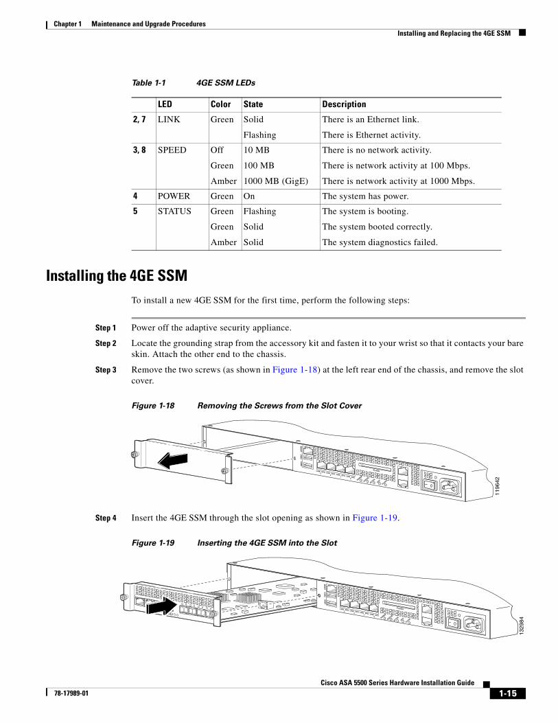
Step 3 Remove the two screws (as shown in Figure 1-18) at the left rear end of the chassis, and remove the slot cover.
Figure 1-18 Removing the Screws from the Slot Cover
Step 4 Insert the 4GE SSM through the slot opening as shown in Figure 1-19.
Figure 1-19 Inserting the 4GE SSM into the Slot
Table 1-1 4GE SSM LEDs
LED Color State Description
2, 7 LINK Green Solid
Flashing
There is an Ethernet link.
There is Ethernet activity.
3, 8 SPEED Off
Green
Amber
10 MB
100 MB
1000 MB (GigE)
There is no network activity.
There is network activity at 100 Mbps.
There is network activity at 1000 Mbps.
4 POWER Green On The system has power.
5 STATUS Green
Green
Amber
Flashing
Solid
Solid
The system is booting.
The system booted correctly.
The system diagnostics failed.
1196
42
LINK SPD3 LINK SPD
2 LINK SPD1 LINK SPD
0
MG
MT
US
B2
US
B1
FLASH
POWER
STATUS
FLASHVPNACTIVE
1329
84
MG
MT
US
B2
US
B1
POW
ERST
ATUS
Cisco SSM-4GE
LNK
SPD01
23
LINK SPD3 LINK SPD
2 LINK SPD1 LINK SPD
0
FLASH
POWER
STATUS
FLASHVPNACTIVE
MG
MT
US
B2
US
B1
1-16Cisco ASA 5500 Series Hardware Installation Guide
78-17989-01
Chapter 1 Maintenance and Upgrade ProceduresInstalling and Replacing the 4GE SSM
Step 5 Attach the screws to secure the 4GE SSM to the chassis.
Step 6 Power on the adaptive security appliance.
Step 7 Check the LEDs. If the 4GE SSM is installed properly the STATUS LED flashes during boot up and is solid when operational.
Step 8 Connect one end of the RJ-45 cable to the port and the other end of the cable to your network devices.
Replacing the 4GE SSMTo replace an existing 4GE SSM, perform the following steps:
Step 1 Power off the adaptive security appliance.
Step 2 Locate the grounding strap from the accessory kit and fasten it to your wrist, so that it contacts your bare skin. Attach the other end to the chassis.
Step 3 Remove the two screws at the left rear end of the chassis.
Step 4 Remove the 4GE SSM. Place it in a static bag and set it aside.
Step 5 Replace the existing card by inserting the new 4GE SSM through the slot opening.
Step 6 Attach the screws to secure the 4GE SSM to the chassis.
Step 7 Power on the adaptive security appliance.
Step 8 Check the LEDs. If the 4GE SSM is installed properly, the POWER LED is solid green and the STATUS LED is flashing during boot up.
Step 9 Connect the RJ-45 cable to the port and the other end of the cable to your network devices.
Installing and Removing the SFP ModulesThe SFP is a hot-swappable input/output device that plugs into the SFP ports. The following SFP module types are supported:
• Long wavelength/long haul 1000BASE-LX/LH (GLC-LH-SM=)
• Short wavelength 1000BASE-SX (GLC-SX-MM=)
This section describes how to install and remove the SFP modules in the adaptive security appliance to provide optical Gigabit Ethernet connectivity. It contains the following topics:
• SFP Module, page 1-16
• Installing the SFP Module, page 1-18
• Removing the SFP Module, page 1-19
SFP Module
The adaptive security appliance uses a field-replaceable SFP module to establish Gigabit connections.
Table 1-2 lists the SFP modules that are supported by the adaptive security appliance.
1-17Cisco ASA 5500 Series Hardware Installation Guide
78-17989-01
Chapter 1 Maintenance and Upgrade ProceduresInstalling and Replacing the 4GE SSM
The 1000BASE-LX/LH and 1000BASE-SX SFP modules are used to establish fiber-optic connections. Use fiber-optic cables with LC connectors to connect to an SFP module. The SFP modules support 850 to 1550 nm nominal wavelengths. The cables must not exceed the required cable length for reliable communications. Table 1-3 lists the cable length requirements.
Use only Cisco certified SFP modules on the adaptive security appliance. Each SFP module has an internal serial EEPROM that is encoded with security information. This encoding provides a way for Cisco to identify and validate that the SFP module meets the requirements for the adaptive security appliance.
Note Only SFP modules certified by Cisco are supported on the adaptive security appliance.
Caution Protect your SFP modules by inserting clean dust plugs into the SFPs after the cables are extracted from them. Be sure to clean the optic surfaces of the fiber cables before you plug them back into the optical bores of another SFP module. Avoid getting dust and other contaminants into the optical bores of your SFP modules. The optics do not work correctly when obstructed with dust.
Warning Because invisible laser radiation may be emitted from the aperture of the port when no cable is connected, avoid exposure to laser radiation and do not stare into open apertures. Statement 70
Table 1-2 Supported SFP Modules
SFP Module Type of Connection Cisco Part Number
1000BASE-LX/LH Fiber-optic GLC-LH-SM=
1000BASE-SX Fiber-optic GLC-SX-MM=
Table 1-3 Cabling Requirements for Fiber-Optic SFP Modules
SFP Module
62.5/125 micron Multimode 850 nm Fiber
50/125 micron Multimode 850 nm Fiber
62.5/125 micron Multimode 1310 nm Fiber
50/125 micron Multimode 1310 nm Fiber
9/125 micron Single-mode 1310 nm Fiber
LX/LH — — 550 m at500 Mhz-km
550 m at400 Mhz-km
10 km
SX 275 m at200 Mhz-km
550 m at500 Mhz-km
— — —
1-18Cisco ASA 5500 Series Hardware Installation Guide
78-17989-01
Chapter 1 Maintenance and Upgrade ProceduresInstalling and Replacing the 4GE SSM
Installing the SFP Module
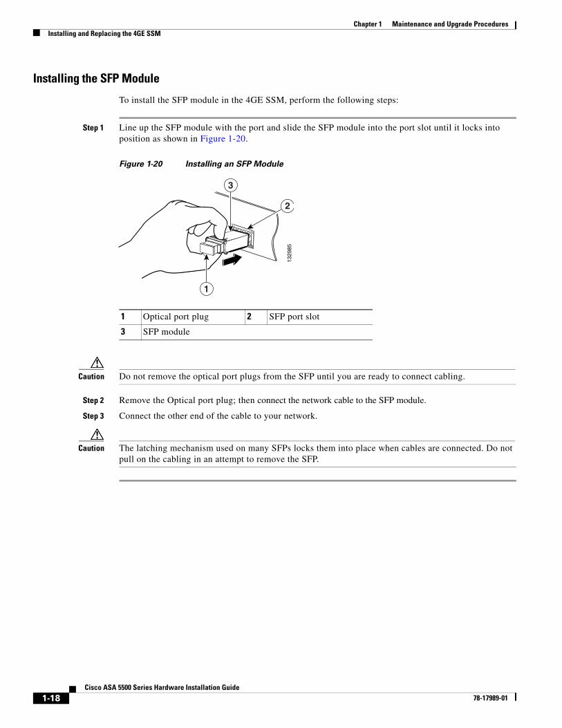
To install the SFP module in the 4GE SSM, perform the following steps:
Step 1 Line up the SFP module with the port and slide the SFP module into the port slot until it locks into position as shown in Figure 1-20.
Figure 1-20 Installing an SFP Module
Caution Do not remove the optical port plugs from the SFP until you are ready to connect cabling.
Step 2 Remove the Optical port plug; then connect the network cable to the SFP module.
Step 3 Connect the other end of the cable to your network.
Caution The latching mechanism used on many SFPs locks them into place when cables are connected. Do not pull on the cabling in an attempt to remove the SFP.
1 Optical port plug 2 SFP port slot
3 SFP module
1329
851
3
2
1-19Cisco ASA 5500 Series Hardware Installation Guide
78-17989-01
Chapter 1 Maintenance and Upgrade ProceduresInstalling and Replacing the 4GE SSM
Removing the SFP Module
The SFP modules have different types of latching devices used to detach the SFP module from a port. The following are the different types of modules:
• Mylar Tab Module
• Actuator/Button SFP Module
• Bale-Clasp SFP Module
• Plastic Collar Module
To remove the SFP module, perform the following steps:
Step 1 Disconnect all cables from the SFP.
Warning Because invisible laser radiation may be emitted from the aperture of the port when no cable is connected, avoid exposure to laser radiation and do not stare into open apertures. Statement 70
Caution The latching mechanism used on many SFPs locks the SFP into place when cables are connected. Do not pull on the cabling in an attempt to remove the SFP.
Step 2 Disconnect the SFP latch as shown in Figure 1-21.
Note SFP modules use various latch designs to secure the module in the SFP port. Latch designs are not linked to SFP model or technology type. For information on the SFP technology type and model, see the label on the side of the SFP.
Figure 1-21 Disconnecting SFP Latch Mechanisms
Step 3 Grasp the SFP on both sides and remove it from the port.
1 Mylar tab 2 Actuator/Button
3 Bale-clasp 4 Plastic collar
1177
22
1 2 3 4
A
B
1-20Cisco ASA 5500 Series Hardware Installation Guide
78-17989-01
Chapter 1 Maintenance and Upgrade ProceduresInstalling and Replacing the Intelligent SSM
Installing and Replacing the Intelligent SSMThe Cisco ASA 5510, Cisco ASA 5520, Cisco ASA 5540 support the AIP SSM and the CSC SSM, also referred to as the intelligent SSM in this document.The AIP SSM runs advanced IPS software that provides security inspection. There are three types of AIP SSM: the AIP SSM 10, AIP SSM 20 and the AIP SSM 40. The AIP SSM 10 and the AIP SSM 20 look identical, but the AIP SSM 20 has a faster processor and more memory than the AIP SSM 10. The AIP SSM 40 has a faster processor and more memory than both the AIP SSM 10 and the AIP SSM 20. Only one module (the AIP SSM 10, AIP SSM 20, or the AIP SSM 40) can populate the slot at a time.
Table 1-4 lists the memory specifications for the AIP SSM 10, AIP SSM 20, and the AIP SSM 40.
For more information on the AIP SSM 10/20/40, see the “Managing the AIP SSM” section in the Cisco Security Appliance Command Line Configuration Guide.
The CSC SSM runs Content Security and Control software. The CSC SSM provides protection against viruses, spyware, spam, and other unwanted traffic. There are two types of CSC SSM: the CSC SSM 10, and the CSC SSM 20. For more information on the CSC SSM 10/20, see the “Managing the CSC SSM” section in the Cisco Security Appliance Command Line Configuration Guide.
Table 1-5 shows the AIP/CSC SSMs supported by each platform:
1-21Cisco ASA 5500 Series Hardware Installation Guide
78-17989-01
Chapter 1 Maintenance and Upgrade ProceduresInstalling and Replacing the Intelligent SSM
This section describes how to install and replace the AIP/CSC SSM in the adaptive security appliance, and includes the following topics:
• Overview, page 1-21
• Installing and Replacing the AIP/CSC SSM, page 1-22
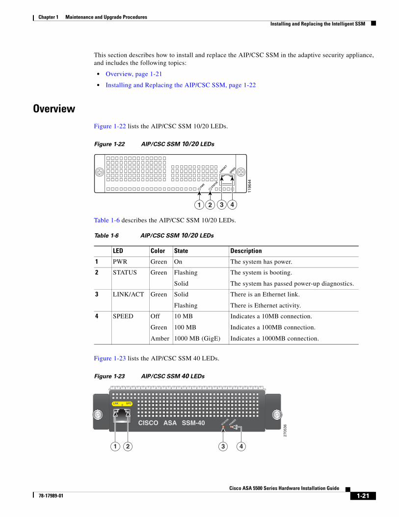
OverviewFigure 1-22 lists the AIP/CSC SSM 10/20 LEDs.
Figure 1-22 AIP/CSC SSM 10/20 LEDs
Table 1-6 describes the AIP/CSC SSM 10/20 LEDs.
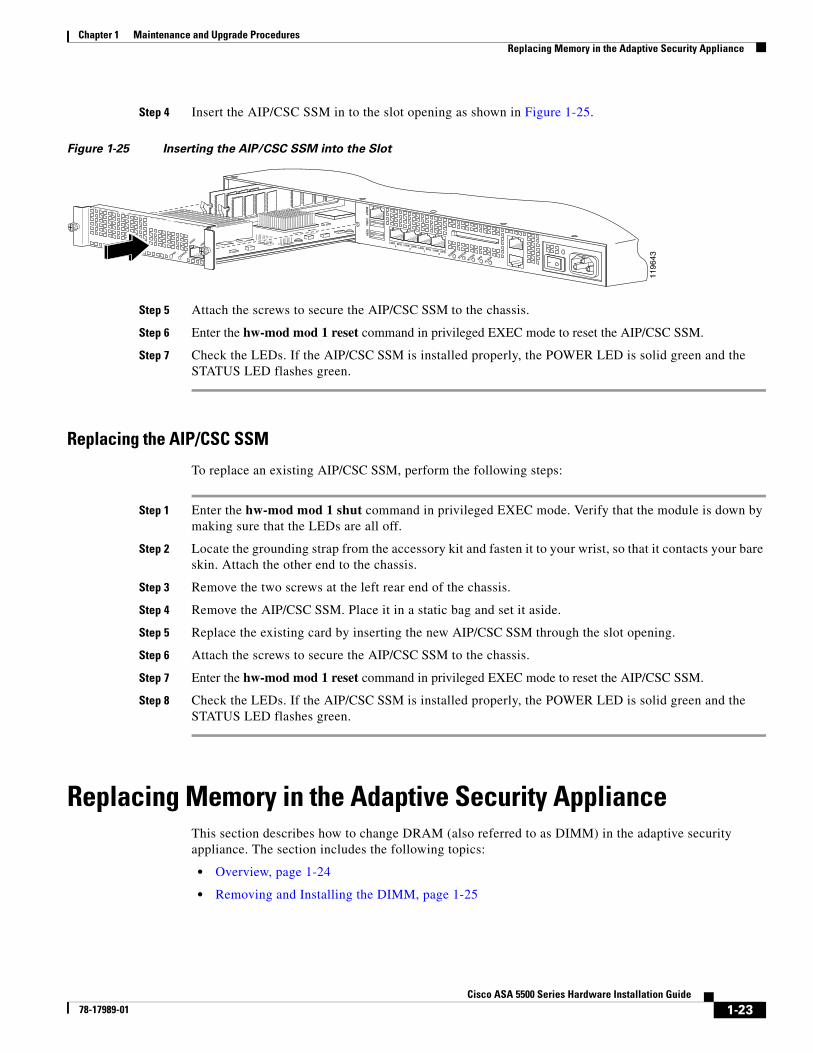
Figure 1-23 lists the AIP/CSC SSM 40 LEDs.
Figure 1-23 AIP/CSC SSM 40 LEDs
1196
44
PWRSTA
TUS
SPEEDLIN
K/ACT
1 2 3 4
Table 1-6 AIP/CSC SSM 10/20 LEDs
LED Color State Description
1 PWR Green On The system has power.
2 STATUS Green Flashing
Solid
The system is booting.
The system has passed power-up diagnostics.
3 LINK/ACT Green Solid
Flashing
There is an Ethernet link.
There is Ethernet activity.
4 SPEED Off
Green
Amber
10 MB
100 MB
1000 MB (GigE)
Indicates a 10MB connection.
Indicates a 100MB connection.
Indicates a 1000MB connection.
2705
36
LNK SPD0
STATUS
POWER
CISCO ASA SSM-40
1 2 3 4
1-22Cisco ASA 5500 Series Hardware Installation Guide
78-17989-01
Chapter 1 Maintenance and Upgrade ProceduresInstalling and Replacing the Intelligent SSM
Table 1-6 describes the AIP/CSC SSM 10/20 LEDs.
Installing and Replacing the AIP/CSC SSMThis section describes how to install and replace the AIP/CSC SSM in the adaptive security appliance. The section includes the following topics:
• Installing the AIP/CSC SSM, page 1-22
• Replacing the AIP/CSC SSM, page 1-23
Installing the AIP/CSC SSM
To install a new AIP/CSC SSM for the first time, perform the following steps:
Step 1 Enter the hw-mod mod 1 shut command in privileged EXEC mode. Verify that the module is down by making sure that the LEDs are all off.
Step 2 Locate the grounding strap from the accessory kit and fasten it to your wrist so that it contacts your bare skin. Attach the other end to the chassis.
Step 3 Remove the two screws at the left rear end of the chassis, and remove the slot cover as shown in Figure 1-24.
Figure 1-24 Removing the Screws from the Slot Cover
Table 1-7 AIP/CSC SSM 40 LEDs
LED Color State Description
1 LNK Green Solid
Flashing
There is an Ethernet link.
There is Ethernet activity.
2 SPEED Off
Green
Amber
10 MB
100 MB
1000 MB (GigE)
Indicates a 10MB connection.
Indicates a 100MB connection.
Indicates a 1000MB connection.
3 STATUS Green Solid
Flashing
The system is booting.
The system has passed power-up diagnostics.
4 POWER Green On The system has power.
1196
42
LINK SPD3 LINK SPD
2 LINK SPD1 LINK SPD
0
MG
MT
US
B2
US
B1
FLASH
POWER
STATUS
FLASHVPNACTIVE
1-23Cisco ASA 5500 Series Hardware Installation Guide
78-17989-01
Chapter 1 Maintenance and Upgrade ProceduresReplacing Memory in the Adaptive Security Appliance
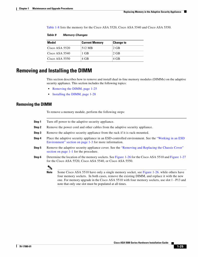
Step 4 Insert the AIP/CSC SSM in to the slot opening as shown in Figure 1-25.
Figure 1-25 Inserting the AIP/CSC SSM into the Slot
Step 5 Attach the screws to secure the AIP/CSC SSM to the chassis.
Step 6 Enter the hw-mod mod 1 reset command in privileged EXEC mode to reset the AIP/CSC SSM.
Step 7 Check the LEDs. If the AIP/CSC SSM is installed properly, the POWER LED is solid green and the STATUS LED flashes green.
Replacing the AIP/CSC SSM
To replace an existing AIP/CSC SSM, perform the following steps:
Step 1 Enter the hw-mod mod 1 shut command in privileged EXEC mode. Verify that the module is down by making sure that the LEDs are all off.
Step 2 Locate the grounding strap from the accessory kit and fasten it to your wrist, so that it contacts your bare skin. Attach the other end to the chassis.
Step 3 Remove the two screws at the left rear end of the chassis.
Step 4 Remove the AIP/CSC SSM. Place it in a static bag and set it aside.
Step 5 Replace the existing card by inserting the new AIP/CSC SSM through the slot opening.
Step 6 Attach the screws to secure the AIP/CSC SSM to the chassis.
Step 7 Enter the hw-mod mod 1 reset command in privileged EXEC mode to reset the AIP/CSC SSM.
Step 8 Check the LEDs. If the AIP/CSC SSM is installed properly, the POWER LED is solid green and the STATUS LED flashes green.
Replacing Memory in the Adaptive Security ApplianceThis section describes how to change DRAM (also referred to as DIMM) in the adaptive security appliance. The section includes the following topics:
• Overview, page 1-24
• Removing and Installing the DIMM, page 1-25
1196
43
PWRSTATUS
SPEED
LINK/ACTLINK SPD
3 LINK SPD2 LINK SPD
1 LINK SPD0
MG
MT
US
B2
US
B1
POWER
STATUS
FLASHVPNACTIVE
1-24Cisco ASA 5500 Series Hardware Installation Guide
78-17989-01
Chapter 1 Maintenance and Upgrade ProceduresReplacing Memory in the Adaptive Security Appliance
Overview
Cisco ASA 5510
The memory kit, ASA5510-MEM-512=, lets you change or add to the memory in your Cisco ASA 5510.
To determine how much memory your adaptive security appliance has, use the show version command; the example below is for the Cisco ASA 5510 chassis:
hostname# show version
Cisco Adaptive Security Appliance Software Version 8.0(4)Device Manager Version 6.1(5)
Compiled on Thu 07-Aug-08 20:53 by buildersSystem image file is "disk0:/asa804-k8.bin"Config file at boot was "startup-config"
ciscoasa up 2 days 10 hoursfailover cluster up 2 days 11 hours
Table 1-8 lists the memory for the Cisco ASA 5510.
Cisco ASA 5520/5540/5550All ASA-5520s and ASA-5540s manufactured before August 2011 have 4 DIMM sockets; all ASA-5520s and ASA-5540s manufactured after this date have 2 DIMM sockets. However, all ASA-5520s and ASA-5540s support only two installed DIMMs.
The ASA-5550 has 4 DIMM sockets, all of which are supported.
The memory kit, ASA5520-MEM-2GB=, lets you change the memory installed in a Cisco ASA 5520. The memory kit, ASA5540-MEM-2GB=, lets you change the memory installed in a Cisco ASA 5540. Two of the ASA5540-MEM-2GB= memory kits also can be used to change the memory in a Cisco ASA 5550.
To determine how much memory your adaptive security appliance currently has, use the show version command; the example below is for the Cisco ASA 5520 chassis:
hostname# show version
Cisco Adaptive Security Appliance Software Version 8.0(0)Device Manager Version 6.0(0)
Compiled on Mon 16-April-07 03:29 by rootSystem image file is "disk0:/cdisk.bin"Config file at boot was "disk0:/main_backup.cfg"
hostname up 2 days 10 hoursfailover cluster up 2 days 11 hours
1-25Cisco ASA 5500 Series Hardware Installation Guide
78-17989-01
Chapter 1 Maintenance and Upgrade ProceduresReplacing Memory in the Adaptive Security Appliance
Table 1-8 lists the memory for the Cisco ASA 5520, Cisco ASA 5540 and Cisco ASA 5550.
Removing and Installing the DIMMThis section describes how to remove and install dual in-line memory modules (DIMMs) on the adaptive security appliance. This section includes the following topics:
• Removing the DIMM, page 1-25
• Installing the DIMM, page 1-28
Removing the DIMM
To remove a memory module, perform the following steps:
Step 1 Turn off power to the adaptive security appliance.
Step 2 Remove the power cord and other cables from the adaptive security appliance.
Step 3 Remove the adaptive security appliance from the rack if it is rack-mounted.
Step 4 Place the adaptive security appliance in an ESD-controlled environment. See the “Working in an ESD Environment” section on page 1-3 for more information.
Step 5 Remove the adaptive security appliance cover. See the “Removing and Replacing the Chassis Cover” section on page 1-1 for the procedure.
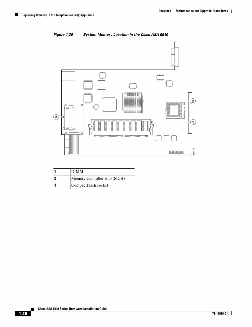
Step 6 Determine the location of the memory sockets. See Figure 1-26 for the Cisco ASA 5510 and Figure 1-27 for the Cisco ASA 5520, Cisco ASA 5540, or Cisco ASA 5550.
Note Some Cisco ASA 5510 have only a single memory socket, see Figure 1-26. while others have four memory sockets. In both cases, remove the existing DIMM, and replace it with the new one. For memory upgrade in the Cisco ASA 5510 with four memory sockets, use slot 1 - P13 and note that only one slot must be populated at all times.
Table 9 Memory Changes
Model Current Memory Change to
Cisco ASA 5520 512 MB 2 GB
Cisco ASA 5540 1 GB 2 GB
Cisco ASA 5550 4 GB 4 GB
1-26Cisco ASA 5500 Series Hardware Installation Guide
78-17989-01
Chapter 1 Maintenance and Upgrade ProceduresReplacing Memory in the Adaptive Security Appliance
Figure 1-26 System Memory Location in the Cisco ASA 5510
1 DIMM
2 Memory Controller Hub (MCH)
3 CompactFlash socket
2810
46
31
2
1-27Cisco ASA 5500 Series Hardware Installation Guide
78-17989-01
Chapter 1 Maintenance and Upgrade ProceduresReplacing Memory in the Adaptive Security Appliance
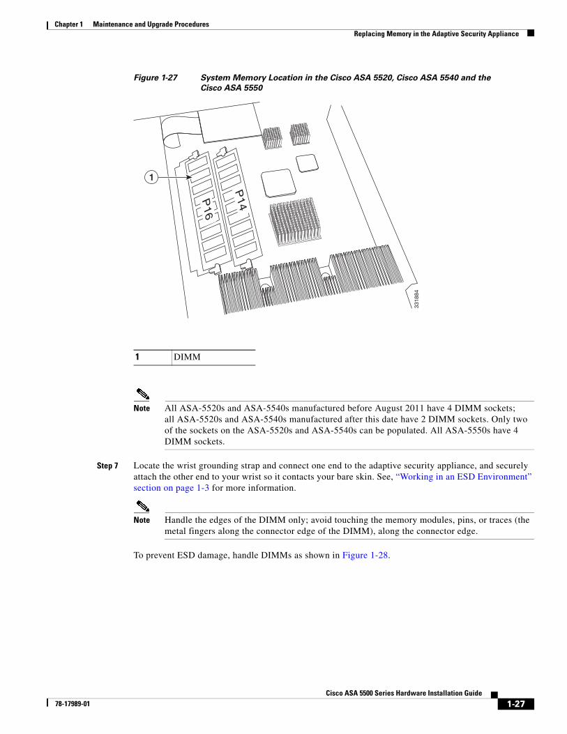
Figure 1-27 System Memory Location in the Cisco ASA 5520, Cisco ASA 5540 and the
Cisco ASA 5550
Note All ASA-5520s and ASA-5540s manufactured before August 2011 have 4 DIMM sockets; all ASA-5520s and ASA-5540s manufactured after this date have 2 DIMM sockets. Only two of the sockets on the ASA-5520s and ASA-5540s can be populated. All ASA-5550s have 4 DIMM sockets.
Step 7 Locate the wrist grounding strap and connect one end to the adaptive security appliance, and securely attach the other end to your wrist so it contacts your bare skin. See, “Working in an ESD Environment” section on page 1-3 for more information.
Note Handle the edges of the DIMM only; avoid touching the memory modules, pins, or traces (the metal fingers along the connector edge of the DIMM), along the connector edge.
To prevent ESD damage, handle DIMMs as shown in Figure 1-28.
1 DIMMP
16
P14
1
3318
84
1-28Cisco ASA 5500 Series Hardware Installation Guide
78-17989-01
Chapter 1 Maintenance and Upgrade ProceduresReplacing Memory in the Adaptive Security Appliance
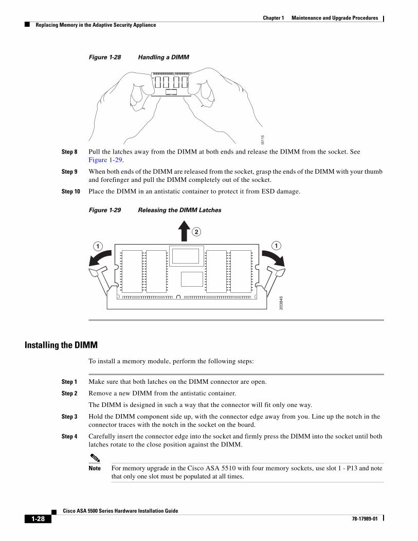
Figure 1-28 Handling a DIMM
Step 8 Pull the latches away from the DIMM at both ends and release the DIMM from the socket. See Figure 1-29.
Step 9 When both ends of the DIMM are released from the socket, grasp the ends of the DIMM with your thumb and forefinger and pull the DIMM completely out of the socket.
Step 10 Place the DIMM in an antistatic container to protect it from ESD damage.
Figure 1-29 Releasing the DIMM Latches
Installing the DIMM
To install a memory module, perform the following steps:
Step 1 Make sure that both latches on the DIMM connector are open.
Step 2 Remove a new DIMM from the antistatic container.
The DIMM is designed in such a way that the connector will fit only one way.
Step 3 Hold the DIMM component side up, with the connector edge away from you. Line up the notch in the connector traces with the notch in the socket on the board.
Step 4 Carefully insert the connector edge into the socket and firmly press the DIMM into the socket until both latches rotate to the close position against the DIMM.
Note For memory upgrade in the Cisco ASA 5510 with four memory sockets, use slot 1 - P13 and note that only one slot must be populated at all times.
3311
5
1 1
2
2038
45
1-29Cisco ASA 5500 Series Hardware Installation Guide
78-17989-01
Chapter 1 Maintenance and Upgrade ProceduresReplacing Memory in the Adaptive Security Appliance
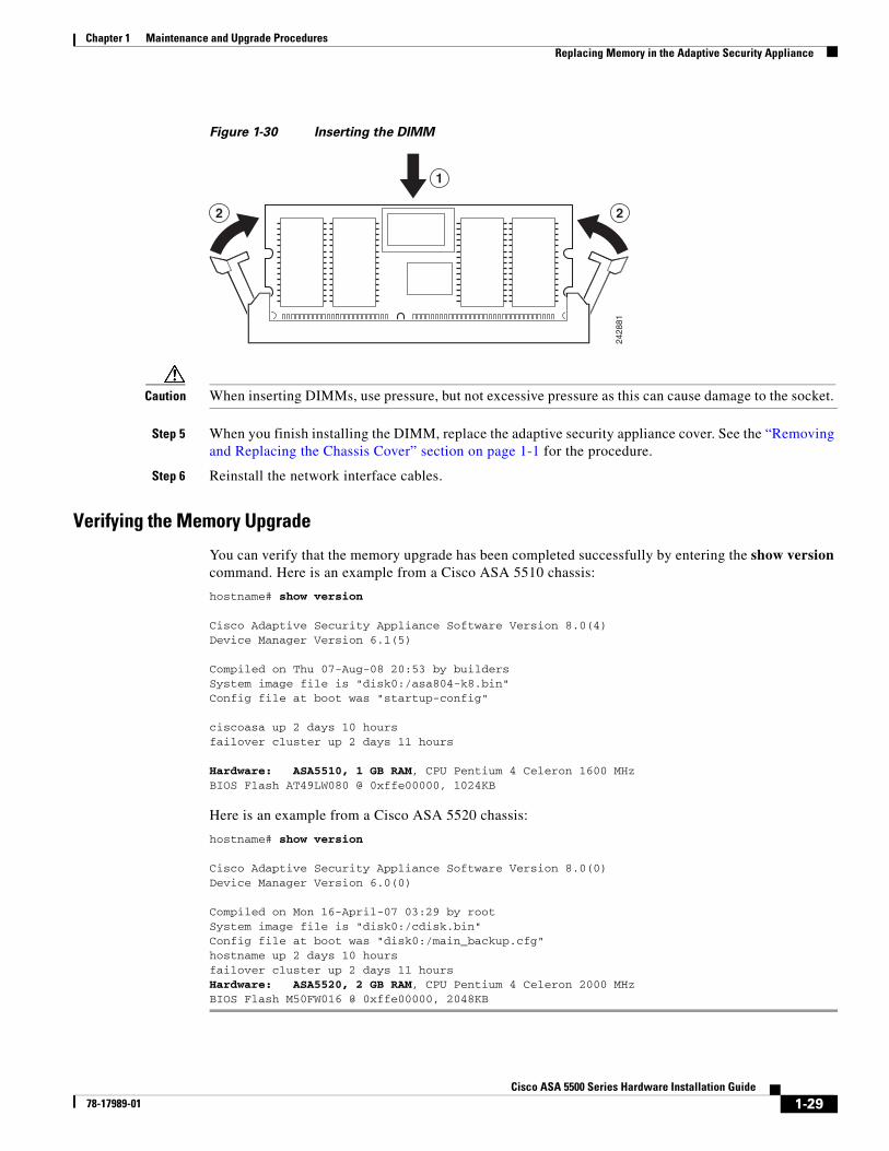
Figure 1-30 Inserting the DIMM
Caution When inserting DIMMs, use pressure, but not excessive pressure as this can cause damage to the socket.
Step 5 When you finish installing the DIMM, replace the adaptive security appliance cover. See the “Removing and Replacing the Chassis Cover” section on page 1-1 for the procedure.
Step 6 Reinstall the network interface cables.
Verifying the Memory Upgrade
You can verify that the memory upgrade has been completed successfully by entering the show version command. Here is an example from a Cisco ASA 5510 chassis:
hostname# show version
Cisco Adaptive Security Appliance Software Version 8.0(4)Device Manager Version 6.1(5)
Compiled on Thu 07-Aug-08 20:53 by buildersSystem image file is "disk0:/asa804-k8.bin"Config file at boot was "startup-config"
ciscoasa up 2 days 10 hoursfailover cluster up 2 days 11 hours
Cisco Adaptive Security Appliance Software Version 8.0(0)Device Manager Version 6.0(0)
Compiled on Mon 16-April-07 03:29 by rootSystem image file is "disk0:/cdisk.bin"Config file at boot was "disk0:/main_backup.cfg"hostname up 2 days 10 hoursfailover cluster up 2 days 11 hoursHardware: ASA5520, 2 GB RAM, CPU Pentium 4 Celeron 2000 MHzBIOS Flash M50FW016 @ 0xffe00000, 2048KB
2 2
1
2428
81
1-30Cisco ASA 5500 Series Hardware Installation Guide
78-17989-01
Chapter 1 Maintenance and Upgrade ProceduresReplacing Memory in the Adaptive Security Appliance


![DSR 5.X/6.X Installation - Part 2/2: Software Installation and … · 2014. 9. 2. · [9] HP Solutions Firmware Upgrade Pack Upgrade Procedures 2.2, 909-2234-001, Latest Revision.](https://static.documents.pub/doc/80x56/602b3f0d24e2bb744110c01d/dsr-5x6x-installation-part-22-software-installation-and-2014-9-2-9.jpg)


![DSR 5.0 Installation - Part 2/2: Software Installation and ...[8] HP Solutions Firmware Upgrade Pack Upgrade Procedures 2.2, 909-2234-001, Latest Revision, Tekelec, 2012 [9] Policy](https://static.documents.pub/doc/80x56/602b3eb37d33a16b5c2fdc3b/dsr-50-installation-part-22-software-installation-and-8-hp-solutions.jpg)


