1 Maintenance manual Conveyor system EM Table of contents System maintenance ................................................................. 2 Introduction........................................................................... 2 Safety considerations .......................................................... 2 Warranty/guarantee ............................................................. 2 Spare/replacement parts ..................................................... 2 Drive units – general inspection ............................................... 3 Worm gear motor and geared motor ................................... 3 Guide for the conveyor chain .............................................. 3 Conveyor chain – general inspection ....................................... 3 Checking the tension of conveyor chain .............................. 3 Slide rails, beams, idlers and bends – general inspection ........ 3 Checking slide rails ............................................................. 3 Conveyor beams, idler ends, and bends ............................. 3 Replacement of conveyor chain ............................................... 4 Removal of conveyor chain ................................................. 4 Fitting the conveyor chain .................................................. 4 Replacement of slide rails ........................................................ 5 Fixing slide rail to the conveyor beam ................................. 5 Drilling slide rail ........................................................................ 5 Fastening aluminium rivets .................................................. 6 Troubleshooting ......................................................................... 7 Appendixes ................................................................................ 8 Appendix A: Spare parts ..................................................... 8 Appendix B: Spare parts ..................................................... 9 Appendix C: Spare parts ................................................... 10
Transcript
1
Maintenance manualConveyor system EM
Table of contentsSystem maintenance ................................................................. 2
Introduction........................................................................... 2Safety considerations .......................................................... 2Warranty/guarantee ............................................................. 2Spare/replacement parts ..................................................... 2
Drive units – general inspection ............................................... 3Worm gear motor and geared motor ................................... 3Guide for the conveyor chain .............................................. 3
Conveyor chain – general inspection ....................................... 3Checking the tension of conveyor chain .............................. 3
Slide rails, beams, idlers and bends – general inspection ........ 3Checking slide rails ............................................................. 3Conveyor beams, idler ends, and bends ............................. 3
Replacement of conveyor chain ............................................... 4Removal of conveyor chain ................................................. 4Fitting the conveyor chain .................................................. 4
Replacement of slide rails ........................................................ 5Fixing slide rail to the conveyor beam ................................. 5
Appendix A: Spare parts ..................................................... 8Appendix B: Spare parts ..................................................... 9Appendix C: Spare parts ................................................... 10
2 System maintenance
System maintenanceIntroductionThe following section is designed to offer assistance for your planned maintenance schedule.
It may become evident that the suggested mainte-nance intervals can be extended to accommodate your local environmental conditions.
Maintenance of the FlexLink conveyor systems should only be carried out by competent personnel, who are familiar with FlexLink equipment.
If there is any doubt as to the most suitable procedure for maintenance, consult your FlexLink supplier.
For non-FlexLink components, such as motors etc., the manufacturer’s maintenance instructions apply.
The instructions supplied should be followed to ensure that the installation runs with a high degree of safety and to minimize the risk of breakdowns which can adversely affect the production.
If a fault occurs on the installation which cannot be rectified with the help of the instructions in the manual, or if unexpected conditions occur during servicing, contact your FlexLink retailer or FlexLink maintenance person-nel.
Safety considerationsBefore starting any maintenance on your FlexLink equip-ment, the following safety instructions must be observed:
• All electricity must be switched off.
• Make sure that the maintenance switch on the drive unit is also switched off and locked in the “off” posi-tion.
• Pneumatic and/or hydraulic power must be discon-nected and any pressure accumulation released.
• Products being transported should, if possible, be removed from the conveyor chain.
• Staff affected must be informed that maintenance work is being undertaken.
Warning
Do not climb onto the equipment.
Warranty/guaranteeFlexLink conveyors are covered by warranty/guarantees as identified within the trading terms issued for each country. Check the warranty conditions for your system before submitting claims etc. If you are in any doubt as to what warranty is applicable to your system, consult your supplying agent or FlexLink Systems direct.
Spare/replacement partsIf there is a demand for spare parts, contact FlexLink Systems or your supplying agent. See Appendix for rec-ommended spare parts.
System maintenance 3
Drive units – general inspection
Worm gear motor and geared motor The worm gear or geared motor is checked in accord-ance with the instructions from the relevant supplier.
Guide for the conveyor chainThe purpose of the guide for the conveyor chain is to guide the return chain correctly in the drive unit.
No slack is permitted at the drive unit since the con-veyor chain is being guided all the time. Special attention must be given to chain elongation in conveyors of this configuration.
Conveyor chain – general inspection
Checking the tension of conveyor chain The chain is made of elastic material. The chain eventu-ally stretches as the material creeps. The extent of the stretch depends on the traction force in the chain. The stretch shows itself on the return side of the beam after the drive unit.
The tension of the conveyor chain should be checked after 2000 hours of operation and thereafter every 4000 hours.
Important:
The chain should be pre-tensioned while the conveyor is stationary, but must never be so tight that there is no play between the chain links on the underside of the drive unit. There should be no appreciable slack on the chain when the conveyor is stationary. This can, however, vary depending on the total length of the chain. If there is too much slack, the noise level will be higher.
If the slack on the conveyor chain is unacceptably large, it must be shortened by splitting the chain and removing the necessary number of links.
Slide rails, beams, idlers and bends – general inspection
Checking slide rails The condition of the slide rails is fundamental to the func-tioning of the installation. It is therefore essential that these are in good condition.
Checking the slide rail with the conveyor chain in place
The slide rail must be checked after every 2000 hours’ operation. Carry on the checking on a stationary con-veyor with the chain in place.
• Check the fastening points on the slide rail (by the idler end unit and after a wheel bend).
• Check the joints on the slide rail.There is one joint after each idler end, wheel bend and drive unit. There should be no gap exceeding 2 mm in these joints. There should also be no overlap-ping of the slide rail in the joints.
Replace the slide rail if necessary, see “Replacement of slide rails” on page 5.
At least once a year or after every 4 000 hours’ operation, the chain should be removed from the beam, and the slide rail carefully checked for wear and deformation.
• Carry out the same checks as were carried out during “Checking the slide rail with the conveyor chain in place”.
• Check the slide rail for wear and tear.
Note
Check in particular the slide rails in plain bends, since the stresses here are particularly high.
• Check the slide rails for scratches and notches.
• Replace the slide rail and fasteners if necessary, see “Replacement of slide rails” on page 5.
Wash the conveyor chain.
Conveyor beams, idler ends, and bendsThe conveyor beams themselves do not normally require any regular inspection.
Be observant for damage arising from external fac-tors, warping or deformation.
Deformation can cause the conveyor chain to jam, resulting in uneven running.
Idler ends and wheel bends do not normally require any special inspections, but they should be checked when the slide rails are inspected.
4 System maintenance
Replacement of conveyor chain
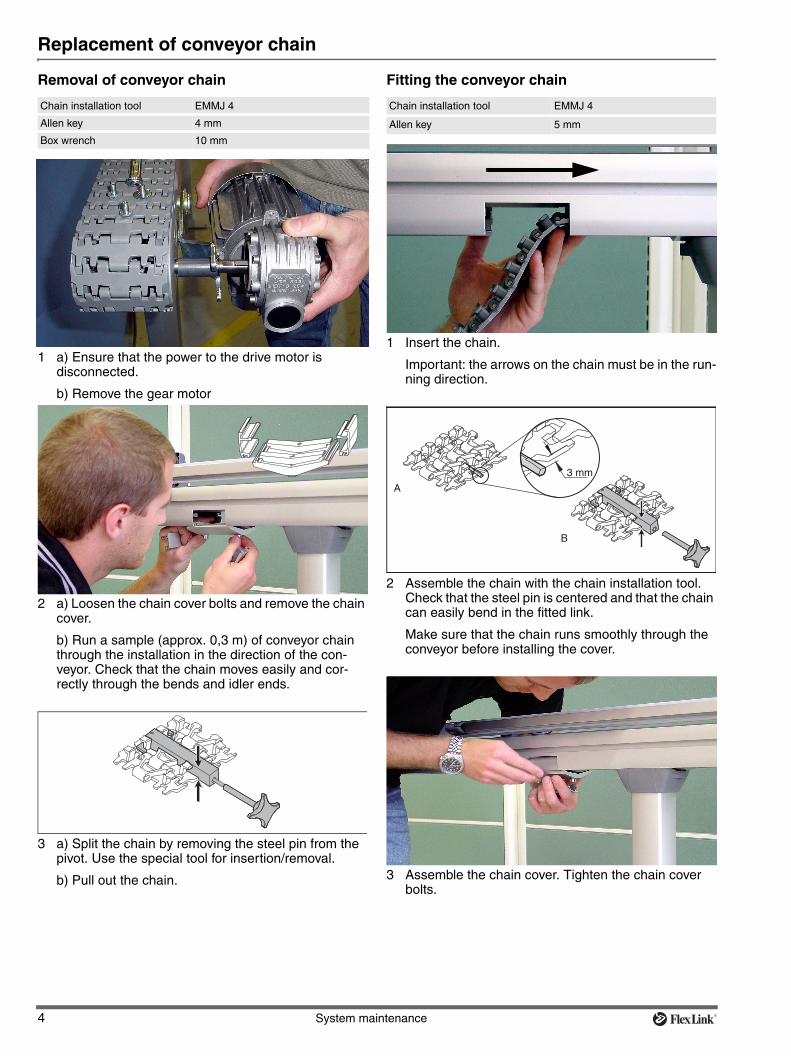
Removal of conveyor chain Fitting the conveyor chain
Chain installation tool EMMJ 4
Allen key 4 mm
Box wrench 10 mm
1 a) Ensure that the power to the drive motor is disconnected.
b) Remove the gear motor
2 a) Loosen the chain cover bolts and remove the chain cover.
b) Run a sample (approx. 0,3 m) of conveyor chain through the installation in the direction of the con-veyor. Check that the chain moves easily and cor-rectly through the bends and idler ends.
3 a) Split the chain by removing the steel pin from the pivot. Use the special tool for insertion/removal.
b) Pull out the chain.
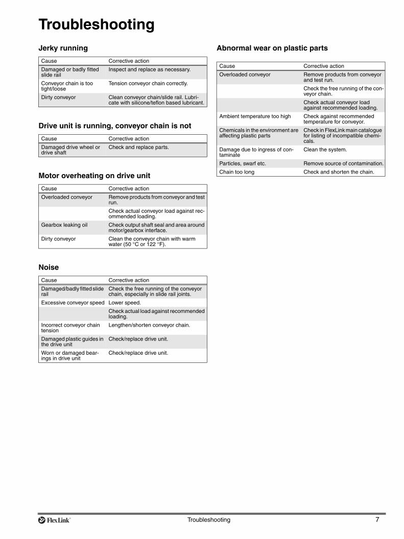
Chain installation tool EMMJ 4
Allen key 5 mm
1 Insert the chain.
Important: the arrows on the chain must be in the run-ning direction.
2 Assemble the chain with the chain installation tool. Check that the steel pin is centered and that the chain can easily bend in the fitted link.
Make sure that the chain runs smoothly through the conveyor before installing the cover.
3 Assemble the chain cover. Tighten the chain cover bolts.
c
System maintenance 5
Replacement of slide rails
It is very important to assemble slide rails correctly to ensure smooth system operation.
Follow the illustrated instructions on the following pages carefully. Observe the following points:
• Single-cut pliers are suitable tools for cutting the slide rails.
• Use a high quality drill bit to avoid forming a shoulder, preferably one which is intended for drilling alumin-ium.
• Use XLAH 4×6 rivets.
• Joints may not be positioned in bends, or in the tran-sition between two sections of beams.
Note
Check the final slide rails visually, as well as running a section of conveyor chain through the installation.
Fixing slide rail to the conveyor beamThe beginning of each slide rail section must be fixed to the beam, since the chain will cause the slide rail to be pushed forward. Slide rail which moves into a wheel bend or a drive unit can block the chain completely.
Drilling slide rail
Procedure:
Figure 1. Single cut pliers
Hand drill
Countersink
1 Press the slide rail into place.
2 Mark the position of the holes.
3 a ) Drill one hole at the beginning of each slide rail section. The holes must be at the leading edge of the joint piece, in the direction of travel, to hold the slide rail in place when the conveyor is in use. Use a well-sharpened drill-bit. Drill bit diameter: 4,2 mm.
b) Make sure that there are no metal chips left under-neath the slide rail.
c) Use a countersink to deburr and countersink the holes.
25 mm
6 mm
a b c
6 System maintenance
Replacement of slide rails (continued)
Fastening aluminium rivets
Mounting:
Rivet crimping pliers/rivet crimping clamp
5051395/3923005
Aluminium rivets XLAH 4×6
1 Insert rivets in the holes.
2 Use rivet crimping clamp or crimping pliers to fasten the rivets. The two crimping tools perform the same task.
3 Check that the rivets do not protrude over the surface of the slide rail.
Check both top and underneath surface of slide rail for protruding metal.
Troubleshooting 7
TroubleshootingJerky running
Drive unit is running, conveyor chain is not
Motor overheating on drive unit
Noise
Abnormal wear on plastic parts
Cause Corrective action
Damaged or badly fitted slide rail
Inspect and replace as necessary.
Conveyor chain is too tight/loose
Tension conveyor chain correctly.
Dirty conveyor Clean conveyor chain/slide rail. Lubri-cate with silicone/teflon based lubricant.
Cause Corrective action
Damaged drive wheel or drive shaft
Check and replace parts.
Cause Corrective action
Overloaded conveyor Remove products from conveyor and test run.
Check actual conveyor load against rec-ommended loading.
Gearbox leaking oil Check output shaft seal and area around motor/gearbox interface.
Dirty conveyor Clean the conveyor chain with warm water (50 °C or 122 °F).
Cause Corrective action
Damaged/badly fitted slide rail
Check the free running of the conveyor chain, especially in slide rail joints.
Excessive conveyor speed Lower speed.
Check actual load against recommended loading.
Incorrect conveyor chain tension
Lengthen/shorten conveyor chain.
Damaged plastic guides in the drive unit
Check/replace drive unit.
Worn or damaged bear-ings in drive unit
Check/replace drive unit.
Cause Corrective action
Overloaded conveyor Remove products from conveyor and test run.
Check the free running of the con-veyor chain.
Check actual conveyor load against recommended loading.
Ambient temperature too high Check against recommended temperature for conveyor.
Chemicals in the environment are affecting plastic parts
Check in FlexLink main catalogue for listing of incompatible chemi-cals.
Damage due to ingress of con-taminate
Clean the system.
Particles, swarf etc. Remove source of contamination.