45
Maintenance Manual MM-10168 RSS 1M Trailer ABS with Roll Stability Support 2S/1M Issued 07-12
Maintenance Manual MM-10168
RSS 1M Trailer ABS with Roll Stability Support2S/1MIssued 07-12

Service Notes
Information contained in this publication was in effect at the time the publication was approved for printing and is subject to change without notice or liability. Meritor WABCO reserves the right to revise the information presented or to discontinue the production of parts described at any time.
Meritor WABCO Maintenance Manual MM-10168 (Issued 07-12)
About This ManualThis manual contains maintenance procedures for Meritor WABCO’s RSS 1M Trailer ABS with Roll Stability Support.
Before You Begin1. Read and understand all instructions and procedures before
you begin to service components.
2. Read and observe all Warning and Caution hazard alert messages in this publication. They provide information that can help prevent serious personal injury, damage to components, or both.
3. Follow your company’s maintenance and service, installation and diagnostics guidelines.
4. Use special tools when required to help avoid serious personal injury and damage to components.
Hazard Alert Messages and Torque Symbols
WARNINGA Warning alerts you to an instruction or procedure that you must follow exactly to avoid serious personal injury and damage to components.
CAUTIONA Caution alerts you to an instruction or procedure that you must follow exactly to avoid damage to components.
@ This symbol alerts you to tighten fasteners to a specified torque value.
How to Obtain Additional Maintenance, Service and Product InformationVisit Literature on Demand at meritor.com to access and order additional information.
Contact the OnTrac Customer Service Center at 866-668-7221 (United States and Canada); 001-800-889-1834 (Mexico); or email [email protected].
How to Obtain Tools and Supplies Specified in This ManualCall Meritor’s Commercial Vehicle Aftermarket at 888-725-9355 to obtain Meritor tools and supplies.

Contents
pg. pg.i Asbestos and Non-Asbestos Fibers1 Section 1: Introduction
RSS 1M Trailer ABSIdentificationRSS 1M Trailer ABS Parts
2 DescriptionWhat Is Meritor WABCO’s RSS 1M Trailer ABS?System ConfigurationHow Trailer ABS Works
3 Section 2: System ComponentsRSS 1M ComponentsHardware
4 TOOLBOX™ SoftwarePLC/J1708 AdapterNOREGON DLA + PLC USB Adapter
5 Section 3: ABS Questions and AnswersRSS 1M Components and FeaturesThe Electronic Control Unit (ECU)Roll Stability Support Questions and AnswersPower Line Carrier (PLC) Communications Questions and
Answers6 What Kind of ABS Indicator Lamps Are Used?
Where Are the ABS Indicator Lamps?ABS Indicator Lamp (on Trailer)
7 Types of Faults
9 Section 4: System ConfigurationsRSS 1M Installation Diagrams
11 Wiring DiagramsPower Cable
12 Section 5: DiagnosticsDiagnosticsImportant PLC Information for Blink Code DiagnosticsTOOLBOX™ Software
13 Vista™ or Windows 7 InstallationsBlink Code DiagnosticsComputer Diagnostics
16 Section 6: Component ReplacementComponent Removal and InstallationCable ConnectionsWheel Speed Sensor
17 ECU/Valve Assembly19 ECU Modulator Valve Assembly20 Air Lines
Replacing the Distance Sensor22 Interaxle Rod
23 Distance Sensor Applications for Trailers with Mechanical Suspension
27 Trailer Labels
28 Section 7: Parameter EntryParameter Entry for RSS 1MVehicle Parameter Settings
29 Air Suspension Parameters31 Mechanical Suspension Parameters
35 Section 8: Sensor Adjustment and Component TestingTestingTest the Wheel Speed SensorsCheck ABS FunctionsEnd of Line Testing
36 End of Line Testing Procedure Using TOOLBOX™ Software
Putting the Trailer into Service40 OnTrac Customer Service Center
Asbestos and Non-Asbestos Fibers
i Meritor WABCO Maintenance Manual MM-10168 (Issued 07-12)
ASBESTOS FIBERS WARNING The following procedures for servicing brakes are recommended to reduce exposure to asbestos fiber dust, a cancer and lung disease hazard. Material Safety Data Sheets are available from Meritor.
Hazard SummaryBecause some brake linings contain asbestos, workers who service brakes must understand the potential hazards of asbestos and precautions for reducing risks. Exposure to airborne asbestos dust can cause serious and possibly fatal diseases, including asbestosis (a chronic lung disease) and cancer, principally lung cancer and mesothelioma (a cancer of the lining of the chest or abdominal cavities). Some studies show that the risk of lung cancer among persons who smoke and who are exposed to asbestos is much greater than the risk for non-smokers. Symptoms of these diseases may not become apparent for 15, 20 or more years after the first exposure to asbestos.
Accordingly, workers must use caution to avoid creating and breathing dust when servicing brakes. Specific recommended work practices for reducing exposure to asbestos dust follow. Consult your employer for more details.
Recommended Work Practices1. Separate Work Areas. Whenever feasible, service brakes in a separate area away from other operations to reduce risks to unprotected persons. OSHA has set a maximum allowable level of exposure for asbestos of 0.1 f/cc as an 8-hour time-weighted average and 1.0 f/cc averaged over a 30-minute period. Scientists disagree, however, to what extent adherence to the maximum allowable exposure levels will eliminate the risk of disease that can result from inhaling asbestos dust. OSHA requires that the following sign be posted at the entrance to areas where exposures exceed either of the maximum allowable levels:
DANGER: ASBESTOSCANCER AND LUNG DISEASE HAZARD
AUTHORIZED PERSONNEL ONLYRESPIRATORS AND PROTECTIVE CLOTHING
ARE REQUIRED IN THIS AREA. 2. Respiratory Protection. Wear a respirator equipped with a high-efficiency (HEPA) filter approved by NIOSH or MSHA for use with asbestos at all times when servicing brakes, beginning with the removal of the wheels.3. Procedures for Servicing Brakes.a. Enclose the brake assembly within a negative pressure enclosure. The enclosure should be
equipped with a HEPA vacuum and worker arm sleeves. With the enclosure in place, use the HEPA vacuum to loosen and vacuum residue from the brake parts.
b. As an alternative procedure, use a catch basin with water and a biodegradable, non-phosphate, water-based detergent to wash the brake drum or rotor and other brake parts. The solution should be applied with low pressure to prevent dust from becoming airborne. Allow the solution to flow between the brake drum and the brake support or the brake rotor and caliper. The wheel hub and brake assembly components should be thoroughly wetted to suppress dust before the brake shoes or brake pads are removed. Wipe the brake parts clean with a cloth.
c. If an enclosed vacuum system or brake washing equipment is not available, employers may adopt their own written procedures for servicing brakes, provided that the exposure levels associated with the employer’s procedures do not exceed the levels associated with the enclosed vacuum system or brake washing equipment. Consult OSHA regulations for more details.
d. Wear a respirator equipped with a HEPA filter approved by NIOSH or MSHA for use with asbestos when grinding or machining brake linings. In addition, do such work in an area with a local exhaust ventilation system equipped with a HEPA filter.
e. NEVER use compressed air by itself, dry brushing, or a vacuum not equipped with a HEPA filter when cleaning brake parts or assemblies. NEVER use carcinogenic solvents, flammable solvents, or solvents that can damage brake components as wetting agents.
4. Cleaning Work Areas. Clean work areas with a vacuum equipped with a HEPA filter or by wet wiping. NEVER use compressed air or dry sweeping to clean work areas. When you empty vacuum cleaners and handle used rags, wear a respirator equipped with a HEPA filter approved by NIOSH or MSHA for use with asbestos. When you replace a HEPA filter, wet the filter with a fine mist of water and dispose of the used filter with care.5. Worker Clean-Up. After servicing brakes, wash your hands before you eat, drink or smoke. Shower after work. Do not wear work clothes home. Use a vacuum equipped with a HEPA filter to vacuum work clothes after they are worn. Launder them separately. Do not shake or use compressed air to remove dust from work clothes.6. Waste Disposal. Dispose of discarded linings, used rags, cloths and HEPA filters with care, such as in sealed plastic bags. Consult applicable EPA, state and local regulations on waste disposal.
Regulatory GuidanceReferences to OSHA, NIOSH, MSHA, and EPA, which are regulatory agencies in the United States, are made to provide further guidance to employers and workers employed within the United States. Employers and workers employed outside of the United States should consult the regulations that apply to them for further guidance.
NON-ASBESTOS FIBERS WARNING The following procedures for servicing brakes are recommended to reduce exposure to non-asbestos fiber dust, a cancer and lung disease hazard. Material Safety Data Sheets are available from Meritor.
Hazard SummaryMost recently manufactured brake linings do not contain asbestos fibers. These brake linings may contain one or more of a variety of ingredients, including glass fibers, mineral wool, aramid fibers, ceramic fibers and silica that can present health risks if inhaled. Scientists disagree on the extent of the risks from exposure to these substances. Nonetheless, exposure to silica dust can cause silicosis, a non-cancerous lung disease. Silicosis gradually reduces lung capacity and efficiency and can result in serious breathing difficulty. Some scientists believe other types of non-asbestos fibers, when inhaled, can cause similar diseases of the lung. In addition, silica dust and ceramic fiber dust are known to the State of California to cause lung cancer. U.S. and international agencies have also determined that dust from mineral wool, ceramic fibers and silica are potential causes of cancer.
Accordingly, workers must use caution to avoid creating and breathing dust when servicing brakes. Specific recommended work practices for reducing exposure to non-asbestos dust follow. Consult your employer for more details.
Recommended Work Practices1. Separate Work Areas. Whenever feasible, service brakes in a separate area away from other operations to reduce risks to unprotected persons.
2. Respiratory Protection. OSHA has set a maximum allowable level of exposure for silica of 0.1 mg/m3 as an 8-hour time-weighted average. Some manufacturers of non-asbestos brake linings recommend that exposures to other ingredients found in non-asbestos brake linings be kept below 1.0 f/cc as an 8-hour time-weighted average. Scientists disagree, however, to what extent adherence to these maximum allowable exposure levels will eliminate the risk of disease that can result from inhaling non-asbestos dust.
Therefore, wear respiratory protection at all times during brake servicing, beginning with the removal of the wheels. Wear a respirator equipped with a high-efficiency (HEPA) filter approved by NIOSH or MSHA, if the exposure levels may exceed OSHA or manufacturers’ recommended maximum levels. Even when exposures are expected to be within the maximum allowable levels, wearing such a respirator at all times during brake servicing will help minimize exposure.
3. Procedures for Servicing Brakes.
a. Enclose the brake assembly within a negative pressure enclosure. The enclosure should be equipped with a HEPA vacuum and worker arm sleeves. With the enclosure in place, use the HEPA vacuum to loosen and vacuum residue from the brake parts.
b. As an alternative procedure, use a catch basin with water and a biodegradable, non-phosphate, water-based detergent to wash the brake drum or rotor and other brake parts. The solution should be applied with low pressure to prevent dust from becoming airborne. Allow the solution to flow between the brake drum and the brake support or the brake rotor and caliper. The wheel hub and brake assembly components should be thoroughly wetted to suppress dust before the brake shoes or brake pads are removed. Wipe the brake parts clean with a cloth.
c. If an enclosed vacuum system or brake washing equipment is not available, carefully clean the brake parts in the open air. Wet the parts with a solution applied with a pump-spray bottle that creates a fine mist. Use a solution containing water, and, if available, a biodegradable, non-phosphate, water-based detergent. The wheel hub and brake assembly components should be thoroughly wetted to suppress dust before the brake shoes or brake pads are removed. Wipe the brake parts clean with a cloth.
d. Wear a respirator equipped with a HEPA filter approved by NIOSH or MSHA when grinding or machining brake linings. In addition, do such work in an area with a local exhaust ventilation system equipped with a HEPA filter.
e. NEVER use compressed air by itself, dry brushing, or a vacuum not equipped with a HEPA filter when cleaning brake parts or assemblies. NEVER use carcinogenic solvents, flammable solvents, or solvents that can damage brake components as wetting agents.
4. Cleaning Work Areas. Clean work areas with a vacuum equipped with a HEPA filter or by wet wiping. NEVER use compressed air or dry sweeping to clean work areas. When you empty vacuum cleaners and handle used rags, wear a respirator equipped with a HEPA filter approved by NIOSH or MSHA, to minimize exposure. When you replace a HEPA filter, wet the filter with a fine mist of water and dispose of the used filter with care.
5. Worker Clean-Up. After servicing brakes, wash your hands before you eat, drink or smoke. Shower after work. Do not wear work clothes home. Use a vacuum equipped with a HEPA filter to vacuum work clothes after they are worn. Launder them separately. Do not shake or use compressed air to remove dust from work clothes.
6. Waste Disposal. Dispose of discarded linings, used rags, cloths and HEPA filters with care, such as in sealed plastic bags. Consult applicable EPA, state and local regulations on waste disposal.
Regulatory GuidanceReferences to OSHA, NIOSH, MSHA, and EPA, which are regulatory agencies in the United States, are made to provide further guidance to employers and workers employed within the United States. Employers and workers employed outside of the United States should consult the regulations that apply to them for further guidance.

1 Introduction
1Meritor WABCO Maintenance Manual MM-10168 (Issued 07-12)
1 IntroductionRSS 1M Trailer ABSThis manual contains service and diagnostic information for Meritor WABCO RSS 1M Trailer ABS with Roll Stability Control.
IdentificationTo identify RSS 1M, check the identification tag on the Electronic Control Unit (ECU). The part number is 480 110 001 0. Figure 1.1.
Figure 1.1
RSS 1M Trailer ABS PartsA list of Meritor WABCO RSS 1M parts can be found in Table A.
For warranty information, contact the OnTrac Customer Service Center at 866-OnTrac1 (668-7221) and ask for TP-99128, Meritor WABCO Trailer ABS Warranty Procedure.
Table A: RSS 1M Parts List
Figure 1.1
Part Number Nomenclature Detail
884 490 281 0 Solenoid Valve Cable 3 Meters
441 044 106 0 Transducer 15 bar (1/4″ NPTF)
449 812 100 0 Transducer Cable 10 Meters
449 351 010 0 Power Cable 1 Meter
449 351 047 0 Power Cable 4.7 Meters
PartNumber
Date CodeFirst Two Digits = Build WeekLast Two Digits = Build Year
1608
480 107 000 0
4009681a
4
449 443 030 0 TAG Generic I/O Cable 3 Meters
884 490 443 0 Tire Inflation Generic I/O Cable
1 Meter
449 765 018 0 Sensor Extension Cable 1.8 Meters
449 765 030 0 Sensor Extension Cable 3 Meters
449 765 050 0 Sensor Extension Cable 5 Meters
449 765 100 0 Sensor Extension Cable 10 Meters
449 535 020 0 Generic I/O Cable 2 Meters
449 535 040 0 Generic I/O Cable 4 Meters
449 535 060 0 Generic I/O Cable 6 Meters
449 865 046 0 WS GIO Cable 2 Meters
449 865 048 0 WS GIO Cable 3 Meters
100 001 012 4 RSS Label Adhesive
TP-95172 ABS Label Adhesive
899 201 833 4 Power Label Adhesive
899 201 842 4 In-Line Filter Label Adhesive
441 050 100 0 Distance Sensor
449 811 020 0 Distance Sensor Cable 2 Meters
441 050 712 2 Distance Sensor Linkage Replacement Only
105 100 002 0 Adjustable Distance Sensor Linkage
100 400 005 0 Distance Sensor “L” Bracket Steel
441 901 715 4 Extension Lever 150 MM
441 050 718 2 Extension Lever Replacement Only
449 865 046 0 Wheel Speed and GIO “Y” Cable
2 Meters – 1 Meter
449 865 048 0 Wheel Speed and GIO “Y” Cable
3 Meters – 1 Meter
499 810 148 0 Solenoid Y Cable 3 Meters
894 607 434 0 Stoplight Activation Cable 1 Meter
449 866 010 0 Multi-Function Octopus Cable
1 Meter
100 400 004 0 Axle Clamp 5.8” diameter
Part Number Nomenclature Detail
1 Introduction
2 Meritor WABCO Maintenance Manual MM-10168 (Issued 07-12)
Description
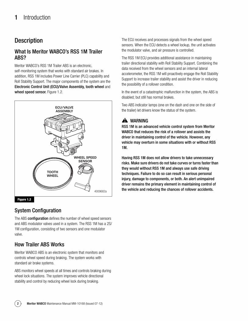
What Is Meritor WABCO’s RSS 1M Trailer ABS?Meritor WABCO’s RSS 1M Trailer ABS is an electronic, self-monitoring system that works with standard air brakes. In addition, RSS 1M includes Power Line Carrier (PLC) capability and Roll Stability Support. The major components of the system are the Electronic Control Unit (ECU)/Valve Assembly, tooth wheel and wheel speed sensor. Figure 1.2.
Figure 1.2
System ConfigurationThe ABS configuration defines the number of wheel speed sensors and ABS modulator valves used in a system. The RSS 1M has a 2S/1M configuration, consisting of two sensors and one modulator valve.
How Trailer ABS WorksMeritor WABCO ABS is an electronic system that monitors and controls wheel speed during braking. The system works with standard air brake systems.
ABS monitors wheel speeds at all times and controls braking during wheel lock situations. The system improves vehicle directional stability and control by reducing wheel lock during braking.
The ECU receives and processes signals from the wheel speed sensors. When the ECU detects a wheel lockup, the unit activates the modulator valve, and air pressure is controlled.
The RSS 1M ECU provides additional assistance in maintaining trailer directional stability with Roll Stability Support. Combining the data received from the wheel sensors and an internal lateral accelerometer, the RSS 1M will proactively engage the Roll Stability Support to increase trailer stability and assist the driver in reducing the possibility of a rollover condition.
In the event of a catastrophic malfunction in the system, the ABS is disabled; but still has normal brakes.
Two ABS indicator lamps (one on the dash and one on the side of the trailer) let drivers know the status of the system.
WARNINGRSS 1M is an advanced vehicle control system from Meritor WABCO that reduces the risk of a rollover and assists the driver in maintaining control of the vehicle. However, any vehicle may overturn in some situations with or without RSS 1M.
Having RSS 1M does not allow drivers to take unnecessary risks. Make sure drivers do not take curves or turns faster than they would without RSS 1M and always use safe driving techniques. Failure to do so can result in serious personal injury, damage to components, or both. An alert unimpaired driver remains the primary element in maintaining control of the vehicle and reducing the chances of rollover accidents.
Figure 1.2
4009682a
ECU/VALVEASSEMBLY
WHEEL SPEEDSENSOR
TOOTHWHEEL
2 System Components
3Meritor WABCO Maintenance Manual MM-10168 (Issued 07-12)
2 System ComponentsRSS 1M Components
Hardware
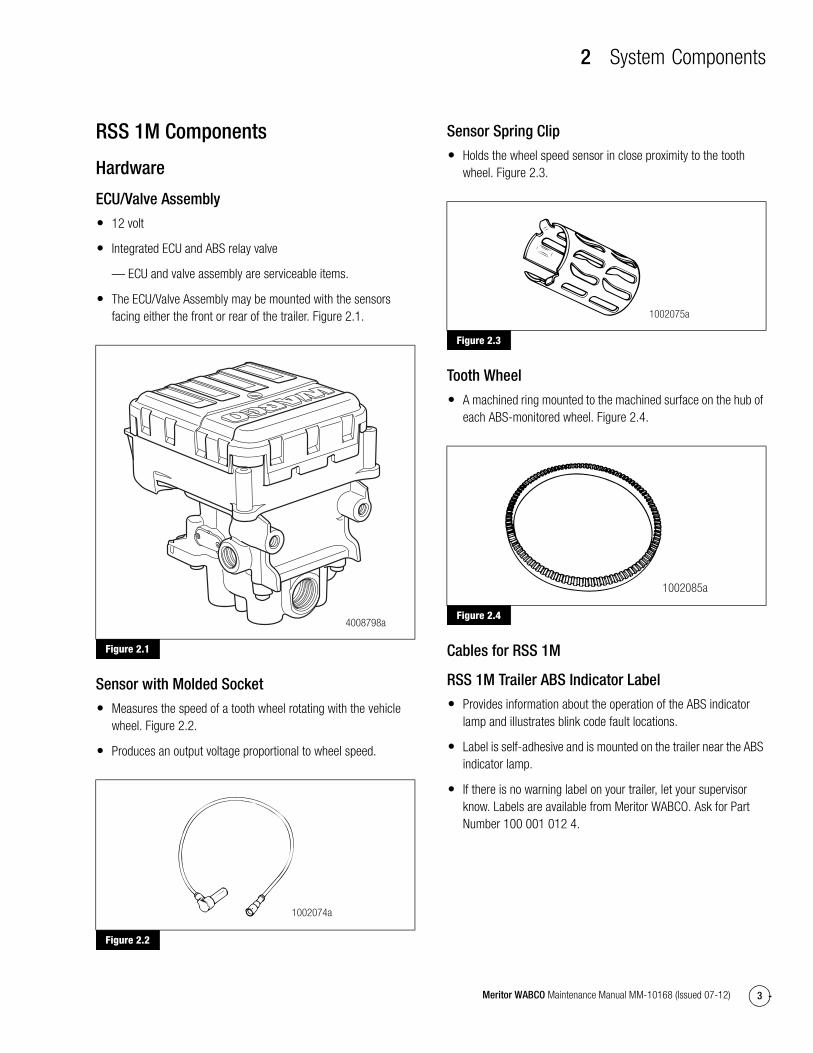
ECU/Valve Assembly
� 12 volt
� Integrated ECU and ABS relay valve
— ECU and valve assembly are serviceable items.
� The ECU/Valve Assembly may be mounted with the sensors facing either the front or rear of the trailer. Figure 2.1.
Figure 2.1
Sensor with Molded Socket
� Measures the speed of a tooth wheel rotating with the vehicle wheel. Figure 2.2.
� Produces an output voltage proportional to wheel speed.
Figure 2.2
Sensor Spring Clip
� Holds the wheel speed sensor in close proximity to the tooth wheel. Figure 2.3.
Figure 2.3
Tooth Wheel
� A machined ring mounted to the machined surface on the hub of each ABS-monitored wheel. Figure 2.4.
Figure 2.4
Cables for RSS 1M
RSS 1M Trailer ABS Indicator Label
� Provides information about the operation of the ABS indicator lamp and illustrates blink code fault locations.
� Label is self-adhesive and is mounted on the trailer near the ABS indicator lamp.
� If there is no warning label on your trailer, let your supervisor know. Labels are available from Meritor WABCO. Ask for Part Number 100 001 012 4.
Figure 2.1
Figure 2.2
4008798a
1002074a
Figure 2.3
Figure 2.4
1002075a
1002085a

2 System Components
4 Meritor WABCO Maintenance Manual MM-10168 (Issued 07-12)
TOOLBOX™ SoftwareTOOLBOX™ Software is a PC-based diagnostics program that can display wheel speed data, test individual components, verify installation wiring and more.
Version 10.5 (or higher) supports RSS 1M with PLC, and runs on a Pentium platform with Windows XP or higher. A PLC/J1708 or DLA + PLC is required. Figure 2.5.
Figure 2.5
PLC/J1708 Adapter� Simulates the tractor ABS lamp, ensuring that the trailer ABS is
capable of “lighting the light.”
� Simulates the trailer ABS lamp, ensuring that the tractor is capable of “lighting the light.”
� Use as a trailer/tractor tester to ensure that PLC is functioning correctly. Figure 2.6.
Figure 2.6
NOREGON DLA + PLC USB Adapter� Simulates the tractor ABS lamp, ensuring that the trailer ABS is
capable of “lighting the light.”
� Simulates the trailer ABS lamp, ensuring that the tractor is capable of “lighting the light.”
� Use as a trailer/tractor tester to ensure that PLC is functioning correctly. Figure 2.7.
Figure 2.7
Figure 2.5
Available from SPX (Kent-Moore), 800-328-6657
Figure 2.6
Available from Noregon Systems, 336-768-4337
4007045a
4003648a
Figure 2.7
Available from Noregon Systems, 336-768-4337
4009718a
COMPUTER
VEHICLEPROPROVEHICLE INTERFACE
DLAPLC+
POWERDATAABS LAMP

3 ABS Questions and Answers
5Meritor WABCO Maintenance Manual MM-10168 (Issued 07-12)
3 ABS Questions and AnswersRSS 1M Components and Features
The Electronic Control Unit (ECU)
How do you activate the ECU?
In a constant-powered system, the ECU activates and then begins a self-diagnostic check of the system when you turn the ignition ON. In a stoplight-powered system, the ECU activates when you apply the brakes. All trailers manufactured on or after March 1, 1998 will be equipped with ABS that has constant power capability with stoplight power as back-up.
How does the ECU respond to a wheel approaching lock-up?
The ECU directs the ABS relay valve to function as a modulator valve and adjust air pressure to the chambers up to five times a second. This pressure adjustment allows a wheel (or wheels) to rotate without locking.
Roll Stability Support Questions and Answers
What is Roll Stability Support?
Roll Stability Support (RSS) is an integrated capability in the RSS 1M ECU that helps reduce the risk of a trailer rollover. By monitoring the trailer’s speed, braking and side-to-side acceleration, the RSS 1M assists the driver in avoiding a potential rollover condition.
How does it work?
The RSS 1M ECU continuously monitors the trailer’s wheel speed and lateral acceleration. When the ECU detects a potentially unstable condition, it requests data from the suspect wheels with a test pulse. The trailer’s reaction to the test pulse determines whether normal braking, ABS braking, or Roll Stability braking is required. The test pulse is not generated under normal braking conditions.
Will trailers with Roll Stability Support work with tractors that have standard ABS only?
Yes. Meritor WABCO’s trailer Roll Stability Support systems will work with standard tractor ABS made by different manufacturers.
Will trailers with Roll Stability Support work with trailers that have standard ABS only?
Yes. Meritor WABCO’s trailer Roll Stability Support systems will work with non-Roll Stability Support ABS systems. Additional pneumatic considerations are shown in Section 4. Plumbing a non-Roll Stability Support ABS system with a Roll Stability Support system can easily be accomplished by following the patented Meritor WABCO P5 plumbing instructions in Section 4.
RSS is permitted on the B-train configuration, as this configuration provides maximum stability support. Contact your Meritor WABCO representative for additional information relating to pneumatic considerations for this configuration.
Power Line Carrier (PLC) Communications Questions and Answers
What is PLC communications?
PLC stands for Power Line Carrier, which is a method used to communicate information by multiplexing data on the same wire used for the ABS electrical power. PLC communications convert signal message data to a radio frequency (RF) signal on top of the +12V power line providing electrical power to the trailer.
What is multiplexing?
Multiplexing means communicating multiple signals or messages on the same transmission media. This provides an efficient and cost effective means by decreasing the number of wires and connectors which otherwise would be needed. Without multiplexing, it could take several wires and connections in order to transmit several different signals to various locations on a vehicle, but with multiplexing these wires and connectors can be significantly reduced.
Why add PLC technology to tractor and trailer ABS?
By adding PLC technology to the tractor and trailer ABS the industry is able to have the most cost effective means to meet the March 1, 2001 FMVSS-121 in-cab trailer indicator lamp mandate with no additional external hardware, harnesses or connectors. Additionally, this new capability of communicating other information between tractor and trailers provides many more opportunities to further improve productivity and safety. With every tractor and trailer currently built having ABS technology, integrating PLC technology into the PC board was the logical choice.

3 ABS Questions and Answers
6 Meritor WABCO Maintenance Manual MM-10168 (Issued 07-12)
How does it work?
The trailer ABS with PLC takes message information to be sent to the tractor and converts it to an RF signal. The signal is then sent over the trailer ABS power line (blue wire) and the tractor ABS with PLC receives the signal. Messages can also be sent from the tractor to the trailer via PLC.
What if a tractor is equipped with PLC technology and the trailer is not, or vice-versa? Will the tractor and trailer ABS function correctly?
Absolutely. If the tractor is equipped with PLC and the trailer is not, or vice-versa, your ABS in-cab trailer indicator lamp will not illuminate, but your ABS will continue to function as normal. To ensure that the trailer ABS is functioning correctly, the trailer ABS indicator lamp mounted on the trailer should be utilized.
What if a tractor has one manufacturer’s ABS with PLC and the trailer has another manufacturer’s ABS with PLC? Will the two systems be compatible and operate the trailer ABS lamp as expected?
Yes. ABS with PLC from different manufacturers are designed to be compatible by controlling the trailer ABS lamp according to the FMVSS-121 standard, even when systems from different manufacturers are connected to each other. However, certain features beyond the control of the trailer ABS indicator lamp may or may not be supported by all devices communicating via PLC. SAE task forces continue to standardize common messages so that maximum compatibility may exist in the future.
How do I diagnose PLC?
PLC can be diagnosed on the trailer using tools designed for PLC diagnostics.
Can I use blink code diagnostics on Enhanced Easy-Stop™ to diagnose PLC?
Yes. Section 5 of this manual describes the method of performing a blink code check using Constant Power (ignition activation). Blink Code 17 indicates a PLC failure.
If PLC does not seem to be operating correctly, but I don’t get a Blink Code 17 when I run a blink code check, what else could be wrong?
If there is no Blink Code 17, the PLC is functioning correctly and does not need to be replaced; however, there could be a problem in the trailer’s wiring harness. Check the wiring system and make the necessary repairs. If the problem persists, contact Meritor WABCO for assistance.
What Kind of ABS Indicator Lamps Are Used?
NOTE: When replacing the bulb, to ensure correct lamp operation use an incandescent type DOT-approved lamp, or a LED with integral load resistor.
Where Are the ABS Indicator Lamps?With RSS 1M, there are two ABS indicator lamps; one on the vehicle dash and one on the side of the trailer.
ABS Indicator Lamp (on Trailer)
What is the function of the ABS indicator lamp?
The indicator lamp enables a driver to monitor the ABS at all times. Refer to the OEM operating manual for the mounting location of the indicator lamp.
How does the indicator lamp operate?
How the indicator lamp operates depends on whether the ABS is powered by stoplight or constant power:
� If the trailer was manufactured prior to February 28, 1998, or was manufactured outside of the United States, the ABS may be either stoplight or constant powered.
� If the trailer was manufactured March 1, 1998 or later — and was manufactured in the United States — it will have constant power capability. This is mandated by Federal Motor Vehicle Safety Standard (FMVSS) 121.
Check your vehicle specification sheet to determine the type of ABS power. Table B in this section illustrates indicator lamp operation on constant powered ABS systems.
The ABS indicator lamp functions only when the brakes are applied when the system is powered by stoplight power.
What does the trailer ABS indicator lamp mean to service personnel?
The trailer ABS indicator lamp on the side of the trailer indicates the status of the trailer ABS. If it comes ON and stays ON when you apply the brakes to a moving vehicle, there is an ABS malfunction. It is normal for the lamp to come ON and go OFF to perform a bulb check, but it should not stay ON when the vehicle is moving above 4 mph (6.45 kph). As with any safety system, it is important not to ignore this indicator. If the indicator lamp indicates a malfunction,

3 ABS Questions and Answers
7Meritor WABCO Maintenance Manual MM-10168 (Issued 07-12)
the vehicle can be operated to complete the trip, but it is important to have it serviced as soon as possible using the appropriate maintenance manual to ensure correct braking performance and that the benefits of ABS remain available to your drivers. Typical ABS indicator lamp mounting locations are illustrated in Figure 3.1.
Figure 3.1
For more information, call Meritor’s Customer Service Center at 866-OnTrac1 (668-7221).
Can you continue to operate a vehicle when the indicator lamp indicates a fault?
Yes. When a fault exists in the ABS, standard braking returns to the affected wheel, and the ABS still controls other monitored wheels. This lets you complete the trip. You should not ignore the indicator lamp and should have the vehicle serviced as soon as possible after the lamp comes ON and stays ON. Indicator lamp operation is shown in Table B.
Figure 3.1
Typical ABS Indicator Lamp Mounting Location on Side of Trailer
1003294d
3 ABS Questions and Answers
8 Meritor WABCO Maintenance Manual MM-10168 (Issued 07-12)
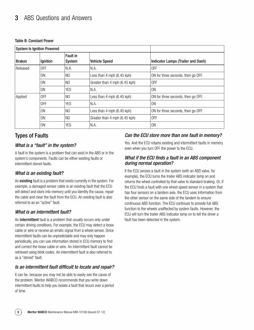
Table B: Constant Power
Types of Faults
What is a “fault” in the system?
A fault in the system is a problem that can exist in the ABS or in the system’s components. Faults can be either existing faults or intermittent stored faults.
What is an existing fault?
An existing fault is a problem that exists currently in the system. For example, a damaged sensor cable is an existing fault that the ECU will detect and store into memory until you identify the cause, repair the cable and clear the fault from the ECU. An existing fault is also referred to as an “active” fault.
What is an intermittent fault?
An intermittent fault is a problem that usually occurs only under certain driving conditions. For example, the ECU may detect a loose cable or wire or receive an erratic signal from a wheel sensor. Since intermittent faults can be unpredictable and may only happen periodically, you can use information stored in ECU memory to find and correct the loose cable or wire. An intermittent fault cannot be retrieved using blink codes. An intermittent fault is also referred to as a “stored” fault.
Is an intermittent fault difficult to locate and repair?
It can be, because you may not be able to easily see the cause of the problem. Meritor WABCO recommends that you write down intermittent faults to help you isolate a fault that recurs over a period of time.
Can the ECU store more than one fault in memory?
Yes. And the ECU retains existing and intermittent faults in memory even when you turn OFF the power to the ECU.
What if the ECU finds a fault in an ABS component during normal operation?
If the ECU senses a fault in the system (with an ABS valve, for example), the ECU turns the trailer ABS indicator lamp on and returns the wheel controlled by that valve to standard braking. Or, if the ECU finds a fault with one wheel speed sensor in a system that has four sensors on a tandem axle, the ECU uses information from the other sensor on the same side of the tandem to ensure continuous ABS function. The ECU continues to provide full ABS function to the wheels unaffected by system faults. However, the ECU will turn the trailer ABS indicator lamp on to tell the driver a fault has been detected in the system.
System Is Ignition Powered
Brakes IgnitionFault in System Vehicle Speed Indicator Lamps (Trailer and Dash)
Released OFF N.A. N.A. OFF
ON NO Less than 4 mph (6.45 kph) ON for three seconds, then go OFF.
ON NO Greater than 4 mph (6.45 kph) OFF
ON YES N.A. ON
Applied OFF NO Less than 4 mph (6.45 kph) ON for three seconds, then go OFF.
OFF YES N.A. ON
ON NO Less than 4 mph (6.45 kph) ON for three seconds, then go OFF.
ON NO Greater than 4 mph (6.45 kph) OFF
ON YES N.A. ON

4 System Configurations
9Meritor WABCO Maintenance Manual MM-10168 (Issued 07-12)
4 System ConfigurationsRSS 1M Installation DiagramsRSS 1M may be tank mounted facing either the front or the rear of the trailer. Additional information regarding RSS 1M installation may be found in Meritor WABCO technical bulletin TP-10169, Trailer ABS with Roll Stability Support (RSS 1M) for Constant Power Trailer with Air or Mechanical Suspensions. To obtain this publication, refer to the Service Notes page on the front inside cover of this manual.
Typical RSS 1M Trailer ABS Installations
NOTE: Meritor WABCO recommends placing sensors on the axle that will provide the most braking performance. The suspension manufacturer can provide this information. Figure 4.1 and Figure 4.2.
Figure 4.1
Figure 4.1
4009127b
PORT 4
2S/1M TANDEM AXLE TRAILER ECU FACING REAR OF TRAILER,SENSORS ON FRONT AXLE
FRONT OFTRAILER
d
c
d
c
SERVICE/CONTROL LINES
SENSOR CABLES
SERVICE BRAKE
SUPPLY AIR
AIR BAG
PORT 2DELIVERY PORTS
PORT 5 – TO AIR BAG –AIR SUSPENSION ONLY
PORT 2DELIVERY PORTS
GI/O 18 TO DISTANCE SENSOR(MECHANICAL SUSPENSION ONLY)

4 System Configurations
10 Meritor WABCO Maintenance Manual MM-10168 (Issued 07-12)
Figure 4.2
Figure 4.2
4009127d
PORT 4
2S/1M TANDEM AXLE TRAILER ECU FACING FRONT OF TRAILER,SENSORS ON REAR AXLE
FRONT OFTRAILER d
c
d
c
SERVICE/CONTROL LINES
SENSOR CABLES
SERVICE BRAKE
SUPPLY AIR
AIR BAG
PORT 2DELIVERY PORTS
PORT 5 – TO AIR BAG –AIR SUSPENSION ONLY
PORT 2DELIVERY PORTS
GI/O 18 TO DISTANCE SENSOR(MECHANICAL SUSPENSION ONLY)

4 System Configurations
11Meritor WABCO Maintenance Manual MM-10168 (Issued 07-12)
Wiring Diagrams
Power CableThe following illustration shows the Power Line Carrier (PLC) power cable interface. Figure 4.3.
Figure 4.3
Figure 4.3
4004071d
CONSTANTPOWER
STOPLIGHTPOWER
INDICATORLIGHT
GROUNDWHITE
BLUE
RED
GREEN AND WHITE
WABCOCONNECTOR
WEATHER PACKCONNECTOR
(MALE)
PERMANENTPOWER
GROUND
WARNINGLAMP
STOPLIGHTPOWER
STOPLIGHTPOWER
2 3
8
1 4
7 6 5
TRAILER HARNESS CONNECTOR
5 Diagnostics
12 Meritor WABCO Maintenance Manual MM-10168 (Issued 07-12)
5 DiagnosticsHazard Alert MessagesRead and observe all Warning and Caution hazard alert messages in this publication. They provide information that can help prevent serious personal injury, damage to components, or both.
WARNINGTo prevent serious eye injury, always wear safe eye protection when you perform vehicle maintenance or service.
The ABS is an electrical system. When you work on the ABS, take the same precautions that you must take with any electrical system to avoid serious personal injury. As with any electrical system, the danger of electrical shock or sparks exists that can ignite flammable substances. You must always disconnect the battery ground cable before working on the electrical system.
DiagnosticsThere are two methods used to get fault information from the ECU:
� TOOLBOX™ Software
� Blink code diagnostics
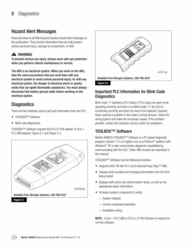
TOOLBOX™ Software requires the PLC/J1708 adapter or DLA + PLC USB adapter. Figure 5.1 and Figure 5.2.
Figure 5.1
Figure 5.2
Important PLC Information for Blink Code DiagnosticsBlink Code 17 indicates a PLC failure. If PLC does not seem to be operating correctly, but there is no Blink Code 17, the ECU is functioning correctly and does not need to be replaced; however, there could be a problem in the trailer’s wiring harness. Check the wiring system and make the necessary repairs. If the problem persists, contact the customer service center for assistance.
TOOLBOX™ SoftwareMeritor WABCO TOOLBOX™ Software is a PC-based diagnostic program. Version 11.0 (or higher) runs on a Pentium platform with Windows XP or later and provides diagnostic capabilities by communicating with the ECU. Trailer ABS screens are described in this manual.
TOOLBOX™ Software has the following functions.
� Supports RSS 1M with PLC and Enhanced Easy-Stop™ ABS.
� Displays both constant and changing information from the ECU being tested.
� Displays both active and stored system faults, as well as the appropriate repair instructions.
� Activates system components to verify:
— System integrity
— Correct component operation
— Installation wiring
NOTE: A DLA + PLC USB or PLC to J1708 interface is required to run this software.
Figure 5.1
Available from Noregon Systems, 336-768-4337
4003648a
Figure 5.2
Available from Noregon Systems, 336-768-4337
4009718a
COMPUTER
VEHICLEPROPROVEHICLE INTERFACE
DLAPLC+
POWERDATAABS LAMP
5 Diagnostics
13Meritor WABCO Maintenance Manual MM-10168 (Issued 07-12)
TOOLBOX™ Software is available from SPX (Kent-Moore), 800-345-2233.
Vista™ or Windows 7 InstallationsIf you have Microsoft Vista™ or Windows 7 installed on your computer, the UAC (User Access Control) must be disabled before installing the TOOLBOX™ Software. Have your computer support personnel or your IT (Information Technology) department perform this change. Once disabled, TOOLBOX™ Software can be installed without issue.
Meritor WABCO does not provide computer support.
If TOOLBOX™ Software has already been installed on your personal computer with Vista™ or Windows 7, your computer support personnel (IT department) must disable the UAC manually. Refer to Vista™ or Windows 7 support documentation for the procedure.
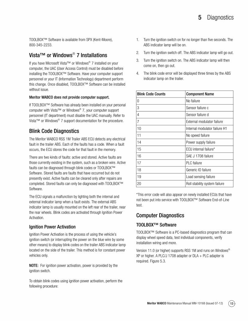
Blink Code DiagnosticsThe Meritor WABCO RSS 1M Trailer ABS ECU detects any electrical fault in the trailer ABS. Each of the faults has a code. When a fault occurs, the ECU stores the code for that fault in the memory.
There are two kinds of faults: active and stored. Active faults are those currently existing in the system, such as a broken wire. Active faults can be diagnosed through blink codes or TOOLBOX™ Software. Stored faults are faults that have occurred but do not presently exist. Active faults can be cleared only after repairs are completed. Stored faults can only be diagnosed with TOOLBOX™ Software.
The ECU signals a malfunction by lighting both the internal and external indicator lamp when a fault exists. The external ABS indicator lamp is usually mounted on the left rear of the trailer, near the rear wheels. Blink codes are activated through Ignition Power Activation.
Ignition Power Activation
Ignition Power Activation is the process of using the vehicle’s ignition switch (or interrupting the power on the blue wire by some other means) to display blink codes on the trailer ABS indicator lamp located on the side of the trailer. This method is for constant power vehicles only.
NOTE: For ignition power activation, power is provided by the ignition switch.
To obtain blink codes using ignition power activation, perform the following procedure:
1. Turn the ignition switch on for no longer than five seconds. The ABS indicator lamp will be on.
2. Turn the ignition switch off. The ABS indicator lamp will go out.
3. Turn the ignition switch on. The ABS indicator lamp will then come on, then go out.
4. The blink code error will be displayed three times by the ABS indicator lamp on the trailer.
*This error code will also appear on newly installed ECUs that have not been put into service with TOOLBOX™ Software End-of-Line test.
Computer Diagnostics
TOOLBOX™ Software
TOOLBOX™ Software is a PC-based diagnostics program that can display wheel speed data, test individual components, verify installation wiring and more.
Version 11.0 (or higher) supports RSS 1M and runs on Windows XP or higher. A PLC/J 1708 adapter or DLA + PLC adapter is required. Figure 5.3.
Blink Code Counts Component Name
0 No failure
3 Sensor failure c
4 Sensor failure d
7 External modulator failure
10 Internal modulator failure H1
11 No speed failure
14 Power supply failure
15 ECU internal failure*
16 SAE J 1708 failure
17 PLC failure
18 Generic IO failure
19 Load sensing failure
20 Roll stability system failure
5 Diagnostics
14 Meritor WABCO Maintenance Manual MM-10168 (Issued 07-12)
Figure 5.3
PLC/J 1708 Adapter or DLA + PLC Adapter
� Simulates the tractor ABS lamp, ensuring that the trailer ABS is capable of “lighting the light.”
� Simulates the trailer ABS lamp, ensuring that the tractor is capable of “lighting the light.”
� Use as a tractor/trailer tester to ensure that PLC is functioning correctly. Figure 5.4 and Figure 5.5.
Figure 5.4
Figure 5.5
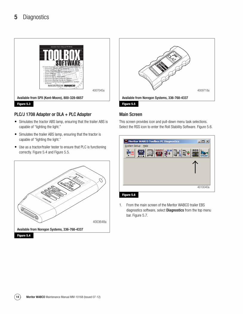
Main Screen
This screen provides icon and pull-down menu task selections. Select the RSS icon to enter the Roll Stability Software. Figure 5.6.
Figure 5.6
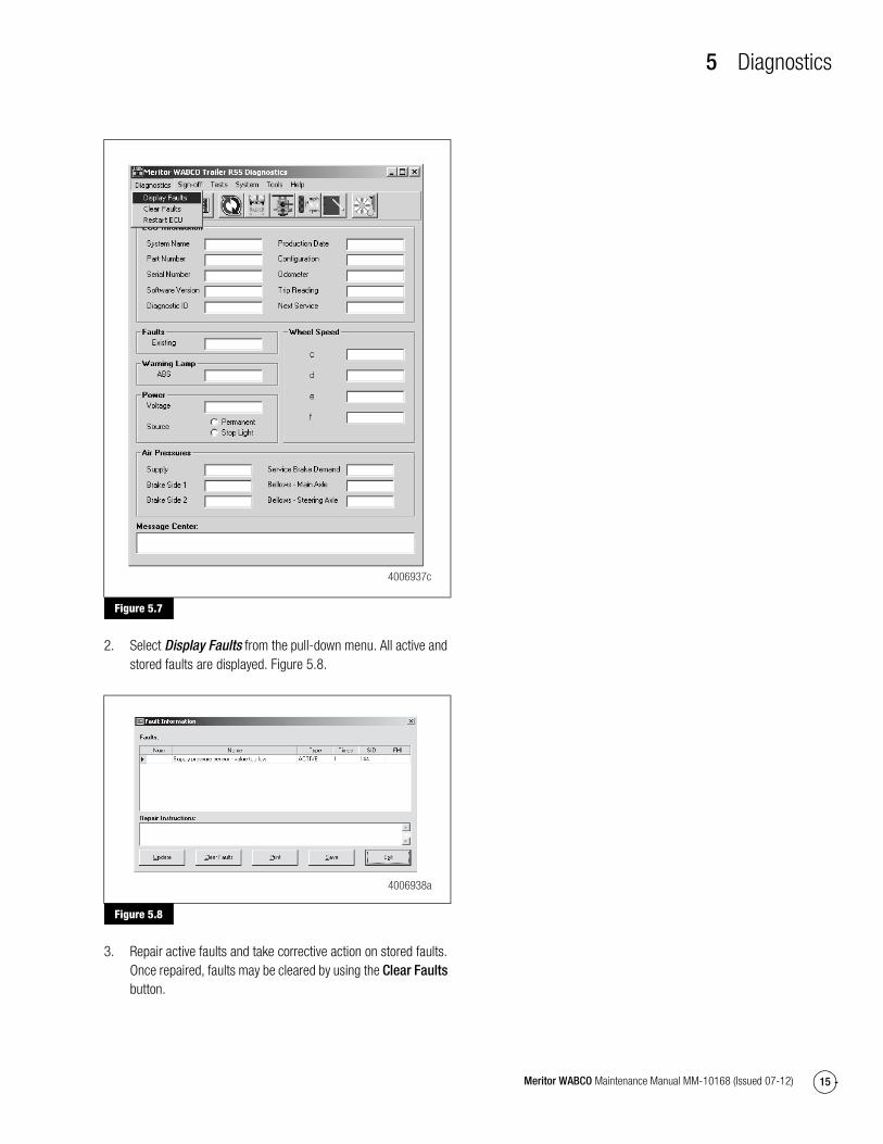
1. From the main screen of the Meritor WABCO trailer EBS diagnostics software, select Diagnostics from the top menu bar. Figure 5.7.
Figure 5.3
Available from SPX (Kent-Moore), 800-328-6657
Figure 5.4
Available from Noregon Systems, 336-768-4337
4007045a
4003648a
Figure 5.5
Available from Noregon Systems, 336-768-4337
Figure 5.6
4009718a
COMPUTER
VEHICLEPROPROVEHICLE INTERFACE
DLAPLC+
POWERDATAABS LAMP
4010040a
5 Diagnostics
15Meritor WABCO Maintenance Manual MM-10168 (Issued 07-12)
Figure 5.7
2. Select Display Faults from the pull-down menu. All active and stored faults are displayed. Figure 5.8.
Figure 5.8
3. Repair active faults and take corrective action on stored faults. Once repaired, faults may be cleared by using the Clear Faults button.
Figure 5.7
Figure 5.8
4006937c
4006938a

6 Component Replacement
16 Meritor WABCO Maintenance Manual MM-10168 (Issued 07-12)
6 Component ReplacementHazard Alert MessagesRead and observe all Warning and Caution hazard alert messages in this publication. They provide information that can help prevent serious personal injury, damage to components, or both.
WARNINGTo prevent serious eye injury, always wear safe eye protection when you perform vehicle maintenance or service.
Park the vehicle on a level surface. Block the wheels to prevent the vehicle from moving. Support the vehicle with safety stands. Do not work under a vehicle supported only by jacks. Jacks can slip and fall over. Serious personal injury and damage to components can result.
The ABS is an electrical system. When you work on the ABS, take the same precautions that you must take with any electrical system to avoid serious personal injury. As with any electrical system, the danger of electrical shock or sparks exists that can ignite flammable substances. You must always disconnect the battery ground cable before working on the electrical system.
NOTE: Disconnect power from the ECU/Valve Assembly before you remove any components. Failure to disconnect power from the ECU can cause faults to be recorded and stored in ECU memory.
CAUTIONWhen welding on an ABS-equipped vehicle is necessary, disconnect the power connector from the ECU to avoid damage to the electrical system and ABS components.
CAUTIONHigh voltages can damage the electronic control unit (ECU). Disconnect all connectors from the ECU before you perform any welding, electrostatic painting, or any other activity that applies high voltage to the vehicle frame. Install blind plugs into the ECU to protect the connector openings. Ground the welding or painting equipment to the part you are working on. If you are working on a moving or insulated component such as an axle, make sure it is correctly grounded through the frame. Refer to the equipment manufacturer’s recommended instructions for correct procedures.
Component Removal and Installation
Cable ConnectionsAll cables connecting to the RSS 1M ECU are secured by means of a yellow locking connector. These connectors slide forward and back in order to lock or release the cable at the ECU. Use a small open-ended wrench to lever the locking connector into the open position. Once an existing cable has been replaced or a new cable installed on an original installation, the connector can be pushed back into the locked position by hand, securely anchoring the cable connection to the ECU. If correctly installed, the use of di-electric grease is not necessary. Zip ties may be used to secure the sensor extension cables to the air lines leading to the wheel ends. Additionally, there are small troughs near the ECU’s delivery ports to attach zip ties.
Wheel Speed Sensor
Remove the Old Sensor
1. Follow the vehicle manufacturer’s instructions to back off the slack adjuster and remove the tire, wheel and drum.
2. Hold the sensor, not the cable, and use a twisting motion to pull the sensor out of its sensor holder.
3. Remove the spring clip from the sensor holder.
4. Remove any fasteners that hold the sensor cable to other components.
5. Disconnect the sensor cable from the extension cable.
Install the New Sensor
Sensor locations vary according to suspension types. Typically, a spring suspension has sensors on the forward axle, and an air suspension has sensors on the rear axle.
1. Apply a mineral oil-based grease that contains molydisulfide to the sensor spring clip and to the body of the sensor. The grease must be anti-corrosive and contain adhesive properties that will continuously endure temperatures from −40° to 300°F (−40° to 150°C).
2. Push the spring clip into the sensor holder from the inboard side, until the spring clip tabs are against the sensor holder. Push the sensor into the spring clip as far as possible. Figure 6.1.

6 Component Replacement
17Meritor WABCO Maintenance Manual MM-10168 (Issued 07-12)
Figure 6.1
3. Route the sensor cable toward the brake chamber, over the brake spider, and behind the axle. Secure the cable to the axle between the brake spider and the suspension brackets. Continue to route the sensor cable behind the spring seats. Secure the cable to the axle one inch from the molded sensor plug. Figure 6.2.
Figure 6.2
4. Install the wheel hub carefully, so that the tooth wheel pushes against the sensor as you adjust the wheel bearings. After installation there should be no gap between the sensor and the tooth wheel. During normal operation a gap of 0.040-inch is allowable.
5. Sensor Output Voltage Test: Use a volt/ohm meter to check the AC output voltage of the sensors while rotating the wheel at approximately one-half revolution per second. Minimum output must be greater than 0.2 volts AC. If minimum output is less than 0.2 volts AC, push the sensor toward the tooth wheel. Recheck the sensor output.
ECU/Valve Assembly
WARNINGRelease all pressure from the air system before you disconnect any components. Pressurized air can cause serious personal injury.
Remove the Old ECU/Valve Assembly
1. Release all pressure from the air system.
2. Attach labels to identify all air lines.
3. Disconnect the air lines from the ECU/Valve Assembly.
4. Disconnect the power cable, additional GI0 cable (if used), and all sensor cables from the ECU/Valve Assembly. Figure 6.3, Figure 6.4 and Figure 6.5.
5. Remove the ECU/Valve Assembly from its mounting location.
6. If the assembly being replaced is under warranty, please return it to the trailer OEM for replacement.
Figure 6.3
Figure 6.1
Figure 6.2
SENSORHOLDER
SPRINGCLIP
SPRINGCLIP TAB
SENSOR
1002100b
1
SENSORCABLE
1002101a
Figure 6.3
4009133a
AIRSUSPENSION
PORT
AUXILIARYSUPPLYPORT
DELIVERYPORTS
5
6 Component Replacement
18 Meritor WABCO Maintenance Manual MM-10168 (Issued 07-12)
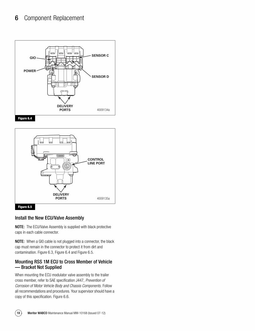
Figure 6.4
Figure 6.5
Install the New ECU/Valve Assembly
NOTE: The ECU/Valve Assembly is supplied with black protective caps in each cable connector.
NOTE: When a GI0 cable is not plugged into a connector, the black cap must remain in the connector to protect it from dirt and contamination. Figure 6.3, Figure 6.4 and Figure 6.5.
Mounting RSS 1M ECU to Cross Member of Vehicle — Bracket Not Supplied
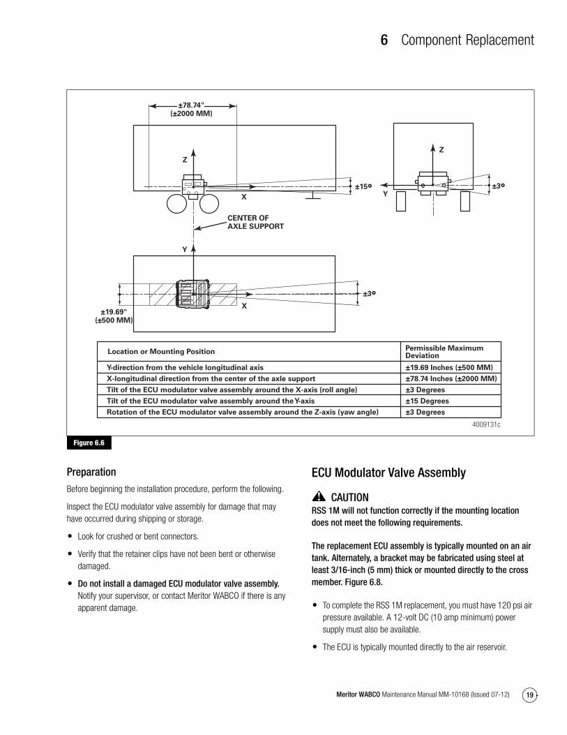
When mounting the ECU modulator valve assembly to the trailer cross member, refer to SAE specification J447, Prevention of Corrosion of Motor Vehicle Body and Chassis Components. Follow all recommendations and procedures. Your supervisor should have a copy of this specification. Figure 6.6.
Figure 6.4
Figure 6.5
4009134aDELIVERY
PORTS
GIO
POWER
SENSOR C
SENSOR D
4009135a
CONTROLLINE PORT
DELIVERYPORTS
4
6 Component Replacement
19Meritor WABCO Maintenance Manual MM-10168 (Issued 07-12)
Figure 6.6
Preparation
Before beginning the installation procedure, perform the following.
Inspect the ECU modulator valve assembly for damage that may have occurred during shipping or storage.
� Look for crushed or bent connectors.
� Verify that the retainer clips have not been bent or otherwise damaged.
� Do not install a damaged ECU modulator valve assembly. Notify your supervisor, or contact Meritor WABCO if there is any apparent damage.
ECU Modulator Valve Assembly
CAUTIONRSS 1M will not function correctly if the mounting location does not meet the following requirements.
The replacement ECU assembly is typically mounted on an air tank. Alternately, a bracket may be fabricated using steel at least 3/16-inch (5 mm) thick or mounted directly to the cross member. Figure 6.8.
� To complete the RSS 1M replacement, you must have 120 psi air pressure available. A 12-volt DC (10 amp minimum) power supply must also be available.
� The ECU is typically mounted directly to the air reservoir.
Figure 6.6
4009131c
±3°
±3°±15°
CENTER OFAXLE SUPPORT
Z
Z
Y
YX
X
±78.74(±2000 MM)
±19.69"(±500 MM)
Y-direction from the vehicle longitudinal axis
X-longitudinal direction from the center of the axle support
Tilt of the ECU modulator valve assembly around the X-axis (roll angle)
Tilt of the ECU modulator valve assembly around the Y-axis
Rotation of the ECU modulator valve assembly around the Z-axis (yaw angle)
±19.69 Inches (±500 MM)
±78.74 Inches (±2000 MM)
±3 Degrees
±15 Degrees
±3 Degrees
Location or Mounting Position Permissible Maximum Deviation

6 Component Replacement
20 Meritor WABCO Maintenance Manual MM-10168 (Issued 07-12)
� The ECU assembly may be mounted level onto a rigid structure of the subframe and must be mounted facing either the front or the rear of the trailer.
� Mount the ECU modulator valve assembly in the center width of the trailer subframe, midway between the axle spacing. Figure 6.6.
� Do not mount sideways. The ECU mounting bolts must point toward either the front or the rear of the trailer.
Installation Procedure
1. Apply SAE-standard, DOT-approved paste-type thread sealant to all NPTF threads. Do not use excessive amounts of sealant.
� Supply ports are 3/4-inch NPTF.
� Delivery, control and air suspension ports are 3/8-inch NPTF.
2. Mount the ECU directly on the air reservoir.
3. Mount the assembly level to a rigid structure of the subframe midway between the side rails, close to the brake chambers the valve serves.
� Attach to the cross member. The center-to-center distance between the two holes must be 3-1/2-inches (89 mm) and mount directly to a rigid structure. Figure 6.7.
OR
� Attach to a mounting bracket with two 9/16-inch (14 mm) mounting holes with 3-1/2-inches (89 mm) center-to-center distance between the two holes. The bracket must be made of cold rolled 1040 to 1080 steel with a reinforcing gusset. Figure 6.8.
Figure 6.7
Figure 6.8
4. Use two 3/8”-16 UNC bolts with corresponding flat and locking washers. Install the nuts and tighten them to 50 ft-lb (68 N�m). @
5. For additional corrosion protection, the ECU modulator assembly may be painted. Mask the exhaust ports before painting. Remove the masking after painting.
6. Washers or spring lock washers are only permitted directly under the nut.
7. The bracket or mounting area must completely cover the bearing surface of the mounting flange.
Air Lines1. Connect the air supply line from the supply tank to the 3/4-inch
NPTF supply port on the ECU modulator valve assembly. Use 5/8-inch minimum O.D. nylon tubing. Tighten the fittings to a maximum of 122 ft-lb (165 N�m). @
2. Connect air delivery lines to the ECU valve assembly. The ports on the bottom of the ECU assembly are 3/8-inch NPTF. Refer to Figure 6.3 for ECU valve port assignments, and Section 4 for air line configuration. Tighten the fittings to 59 ft-lb (80 N�m). @
Replacing the Distance SensorThe Distance Sensor is used only with Roll Stability equipped trailers that have mechanical (spring) suspensions. Trailers equipped with air suspensions do not use a Distance Sensor with their RSS 1M system.
Figure 6.7
4009679b
3-1/2"(89 MM)
GIO/18
POWER/14
ABS d/4
ABS c/3
Figure 6.8
4009129a

6 Component Replacement
21Meritor WABCO Maintenance Manual MM-10168 (Issued 07-12)
The Distance Sensor is attached to the trailer structure or cross member. In some cases, the trailer OEM may have it attached to a fabricated bracket. The distance sensor should be mounted close to the center of the axle. Figure 6.9.
Figure 6.9
Remove the Old Distance Sensor
1. Disconnect the cable attached to the Distance Sensor. Figure 6.10.
Figure 6.10
2. Remove the bolt that attaches the Distance Sensor Lever to the Distance Sensor arm.
3. Remove the two bolts that attach the Distance Sensor to the cross member or bracket.
4. Remove the Distance Sensor.
Install the New Distance Sensor
1. Install the Distance Sensor to the cross member or bracket near the center of the trailer with the two bolts previously used to mount the replaced sensor. Figure 6.10.
2. Attach the Distance Sensor Lever to the Distance Sensor arm.
Figure 6.9
4010233a
DISTANCESENSOR
DISTANCESENSORLINKAGE
Figure 6.10
4010234a
DISTANCESENSOR
DISTANCESENSORLINKAGE
6 Component Replacement
22 Meritor WABCO Maintenance Manual MM-10168 (Issued 07-12)
3. Connect the Distance Sensor cable.
4. Once the Distance Sensor has been replaced, it must be calibrated before putting the trailer back into service. Refer to Section 8 for Distance Sensor Calibration.
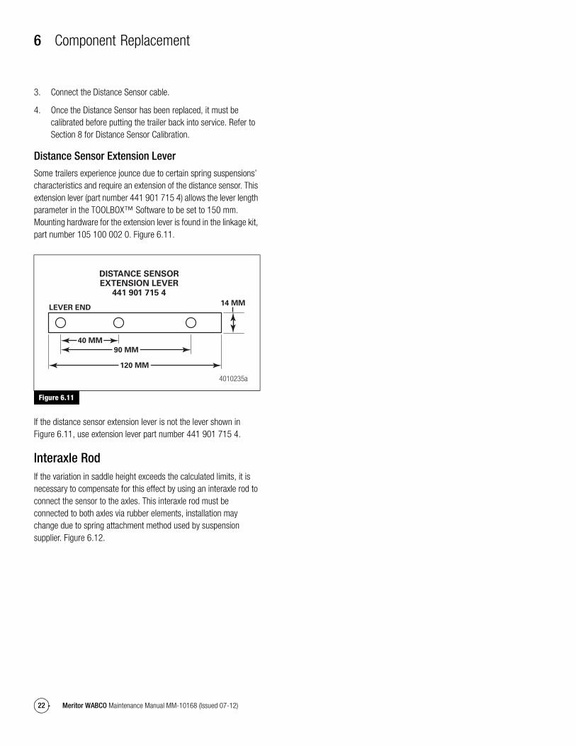
Distance Sensor Extension Lever
Some trailers experience jounce due to certain spring suspensions’ characteristics and require an extension of the distance sensor. This extension lever (part number 441 901 715 4) allows the lever length parameter in the TOOLBOX™ Software to be set to 150 mm. Mounting hardware for the extension lever is found in the linkage kit, part number 105 100 002 0. Figure 6.11.
Figure 6.11
If the distance sensor extension lever is not the lever shown in Figure 6.11, use extension lever part number 441 901 715 4.
Interaxle RodIf the variation in saddle height exceeds the calculated limits, it is necessary to compensate for this effect by using an interaxle rod to connect the sensor to the axles. This interaxle rod must be connected to both axles via rubber elements, installation may change due to spring attachment method used by suspension supplier. Figure 6.12.
Figure 6.11
4010235a
14 MMLEVER END
DISTANCE SENSOREXTENSION LEVER
441 901 715 4
40 MM
90 MM
120 MM

6 Component Replacement
23Meritor WABCO Maintenance Manual MM-10168 (Issued 07-12)
Figure 6.12
The distance sensor must be connected at half of the distance between both axles using the rod with a coupling piece, part number 433 401 033 0. The rod, which will be provided by the trailer manufacturer, must have an L-profile of at least 30 x 30 mm or a tube with at least a 25 mm diameter. Figure 6.13.
Figure 6.13
Distance Sensor Applications for Trailers with Mechanical Suspension
Calibration and Restrictions
Single-Axle Semi Trailer
No special precautions must be taken into account. The calibration of single axle trailers must be performed according to the calibration instructions that follow.
Two-Axle Semi Trailer
Two-axle trailers with mechanical suspension deflection values can be affected by the tractor fifth wheel height variance. A change in this value from the calibrated value can affect the performance of the RSS interventions. Figure 6.14.
Figure 6.14
Fifth Wheel Height Variation Restrictions
To minimize the effect of variation in fifth wheel height that might occur during operation, the following conditions must be satisfied:
� Installation of the distance sensor on the rear axle
� Calibration to be performed with the lowest fifth wheel height which may occur during operation.
Figure 6.12
4009867a
1/2
1
L >30 X 30 MM
190 MM
Figure 6.13
4009868a
Figure 6.14
4009869a

6 Component Replacement
24 Meritor WABCO Maintenance Manual MM-10168 (Issued 07-12)
This procedure will minimize the load measurement error caused by any increase of fifth wheel height from the calibration height. The following diagram (Figure 6.15) shows the limitations for the admissible increase of the fifth wheel height:
Figure 6.15
The engineering-generated diagram reflects the relationship between vehicle wheel base, spring deflection and admissible variation of fifth wheel height. Wheel base means the distance between king pin and middle of the bogie. Deflection means the maximum deflection between laden and unladen status.
Example:
For a vehicle with a wheel base of 46 ft and a suspension deflection of 1 inch, a variation of fifth wheel height of 5 inches is acceptable (e.g. if vehicle was calibrated at 45 inches initially, the saddle height may vary between 45 inches and 50 inches).
NOTE:
� In case of slider bogies, the shortest possible wheel base is to be considered
� In case of bogies with wide spread axles (rocker length bigger than 20 inches), the admissible range of saddle height variation is reduced by 30%
� If the distance sensor needs to be installed on the front axle, please contact Meritor WABCO for assistance
Calibration
To calibrate the mechanical suspension, the following data must be available.
Deflection of the Bogie from Unladen to Laden Condition
The deflection is very important to provide the RSS with the right information to calculate the actual axle load.
Figure 6.15
4009870a
WHEEL BASE(FEET)
60
50
46
40
30
20
100,4 0,6 0,8 1 1,2 1,4 1,6 1,8 2
SPRING DEFLECTION (INCH)
2"
3"
4"
5"
6"
7"
8"
9"
10"
1"
SADDLEHEIGHT
VARIATION
SADDLE HEIGHT VARIATION RESTRICTIONS

6 Component Replacement
25Meritor WABCO Maintenance Manual MM-10168 (Issued 07-12)
NOTE: Incorrect information regarding the axle load can cause undesired interventions of the RSS system.
The values can be supplied by the suspension supplier. Figure 6.16. It is important to determine the correct suspension unladen load value, if calculating values from suspension supplier load versus deflection graph. Refer to the example below.
Example:
Characteristic of spring deflection provided by axle or spring manufacturer
Figure 6.16
Table C: Example for Two Axle Semi Trailer
Figure 6.16
4009871a
20
18
16
14
12
10
8
6
4
2
0 .2 .6 1.0
DEFLECTION IN INCHES
SUSPENSION LOAD LADEN = 8,000 LB
SUSPENSION LOAD UNLADEN = 1,050 LB
SUSPENSION LOAD: WHEEL LOAD REDUCED BY AXLE WEIGHT0,9"23 MM
1.4 1.8
LO
AD
PE
R S
PR
ING
IN
PO
UN
DS
(X
1,0
00
)
Bogie Load
Bogie Load without Axle Weight
Suspension Load per Wheel
Max. Load: 34,000 lb 32,000 lb 8,000 lb
Unladen Load: 6,000 lb 4,200 lb 1, 050 lb
Unladen Deflection:
0.25 inch
Laden Deflection:
1.15 inch
Difference (Input for Parameter Setting)
0.9 inch = 23 mm
Bogie Load
Bogie Load without Axle Weight
Suspension Load per Wheel

6 Component Replacement
26 Meritor WABCO Maintenance Manual MM-10168 (Issued 07-12)
Alternative Method to Determine Suspension Deflection
1. With the trailer unloaded, measure from the top of the axle tub (A) to a fixed point (B) on the underside of the trailer. Note the distance. Figure 6.17.
Figure 6.17
2. With the trailer loaded (maximum load), measure from the same points (A and B) that were used for the trailer unloaded measurement. It is important to ensure the maximum load is distributed uniformly (front to back, left to right) to avoid an inclined trailer condition. Note the distance.
3. Subtract the trailer loaded distance from the trailer unloaded distance. Note the difference. This is the spring deflection rate for this trailer.
NOTE: Provide the deflection rate in millimeters.
Negative Spring Deflection
Negative spring deflection means that the suspension is moving beyond the unladen position due to the clearance in the suspension.
This value is important to determine the correct length “l” of the distance sensor. Figure 6.18. It must be ensured that under every condition, the length of the lever is longer than the negative deflection to prevent the lever from turning over. If the lever is too long, the optimal resolution will be affected and lead to less precise axle load measurements. A lever length of 150 mm should be sufficient for the most types of axles. The negative deflection can be measured by lifting the axle without the distance sensor with a suitable jack until the other axle does not touch the ground. Contact Meritor WABCO for applications which may require a longer extension arm length greater than 150 mm.
Figure 6.18
Conditions for Calibration
� The correct values are entered and stored in the ECU for unladen and laden deflections and loads.
� The trailer must be located on a level surface.
� The trailer must be in an unladen condition.
� In the unladen condition, the lever of the distance sensor must be in the horizontal position.
� Ensure that the distance sensor has been installed correctly and the lever can move without collision with the trailer frame. Refer to the installation guide.
� Chassis level
— Single-Axle Semi Trailer:
No special requirements.
— Two-Axle Semi Trailer:
The king pin must be in the lowest position which may occur during trailer operation with different tractors.
Figure 6.17
4009872a
B
A
Figure 6.18
4009873a
EXTENSION
DISTANCESENSOR
AXLE
LINKAGE 1
6 Component Replacement
27Meritor WABCO Maintenance Manual MM-10168 (Issued 07-12)
� During calibration, the trailer brakes have to be released (service brake and spring brake).
The final calibration is done using TOOLBOX™ Software. Please follow the software instructions.
Trailer LabelsBefore releasing the trailer:
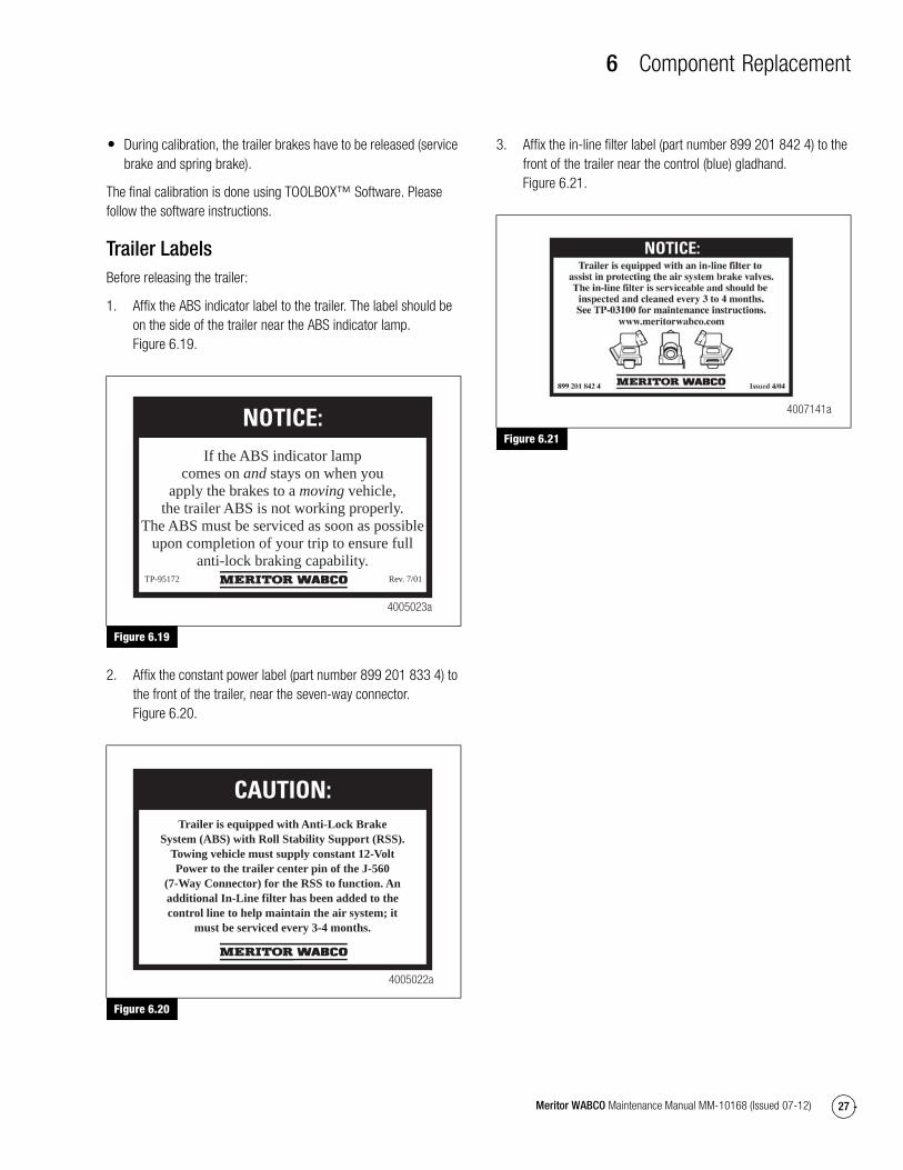
1. Affix the ABS indicator label to the trailer. The label should be on the side of the trailer near the ABS indicator lamp. Figure 6.19.
Figure 6.19
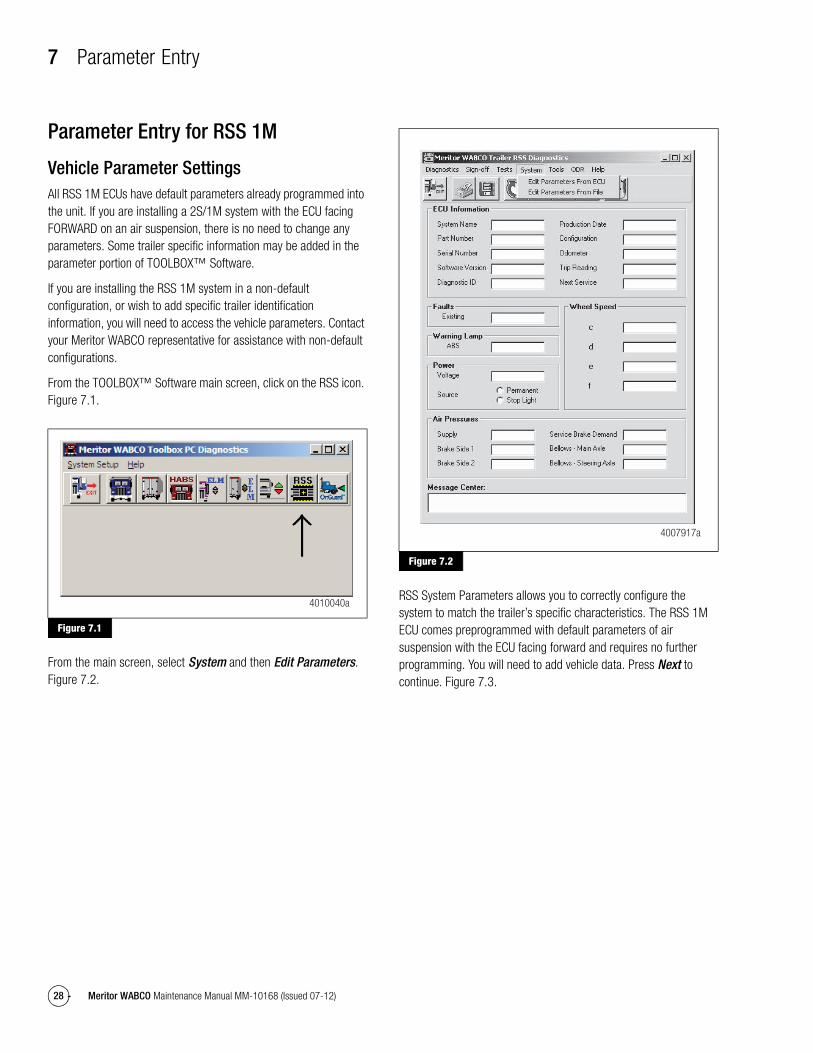
2. Affix the constant power label (part number 899 201 833 4) to the front of the trailer, near the seven-way connector. Figure 6.20.
Figure 6.20
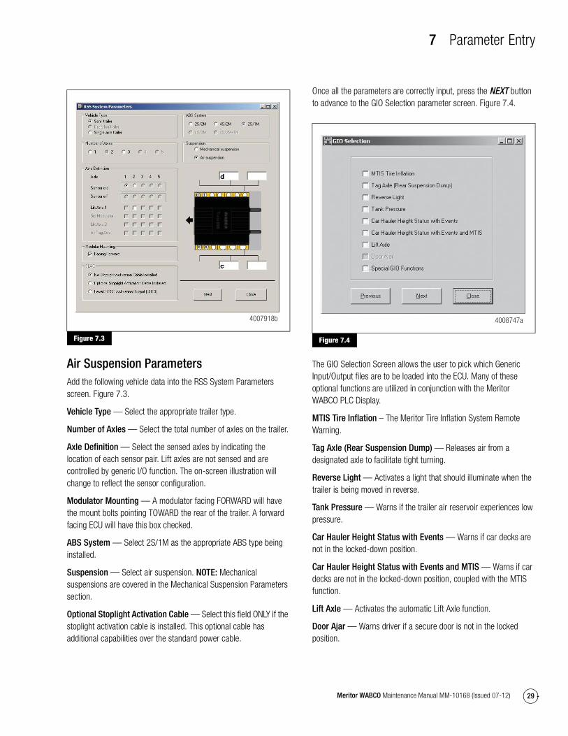
3. Affix the in-line filter label (part number 899 201 842 4) to the front of the trailer near the control (blue) gladhand. Figure 6.21.
Figure 6.21
Figure 6.19
Figure 6.20
If the ABS indicator lamp comes on and stays on when you
apply the brakes to a moving vehicle, the trailer ABS is not working properly.
The ABS must be serviced as soon as possible upon completion of your trip to ensure full
anti-lock braking capability.
NOTICE:
TP-95172 Rev. 7/01
4005023a
Trailer is equipped with Anti-Lock BrakeSystem (ABS) with Roll Stability Support (RSS).
Towing vehicle must supply constant 12-VoltPower to the trailer center pin of the J-560
(7-Way Connector) for the RSS to function. Anadditional In-Line filter has been added to thecontrol line to help maintain the air system; it
must be serviced every 3-4 months.
CAUTION:
4005022a
Figure 6.21
4007141a
7 Parameter Entry
28 Meritor WABCO Maintenance Manual MM-10168 (Issued 07-12)
7 Parameter EntryParameter Entry for RSS 1M
Vehicle Parameter SettingsAll RSS 1M ECUs have default parameters already programmed into the unit. If you are installing a 2S/1M system with the ECU facing FORWARD on an air suspension, there is no need to change any parameters. Some trailer specific information may be added in the parameter portion of TOOLBOX™ Software.
If you are installing the RSS 1M system in a non-default configuration, or wish to add specific trailer identification information, you will need to access the vehicle parameters. Contact your Meritor WABCO representative for assistance with non-default configurations.
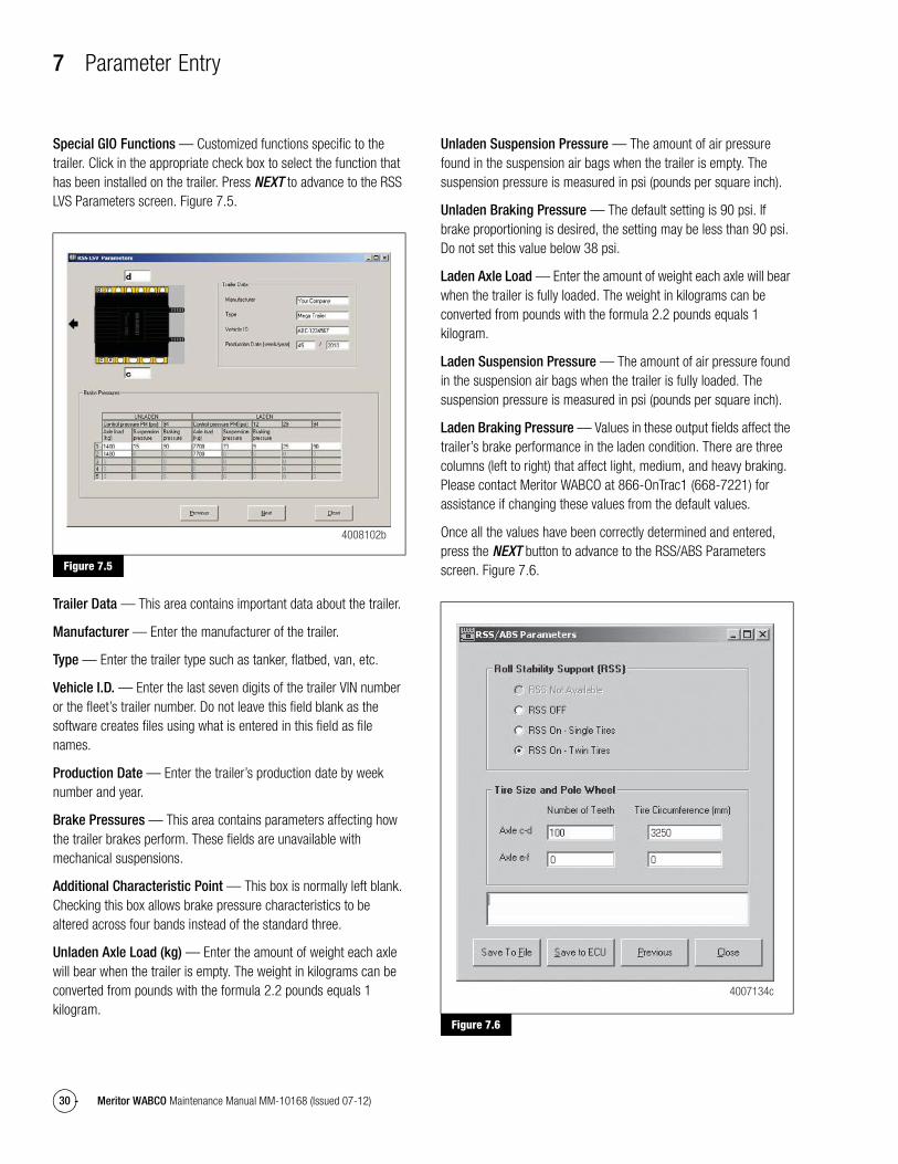
From the TOOLBOX™ Software main screen, click on the RSS icon. Figure 7.1.
Figure 7.1
From the main screen, select System and then Edit Parameters. Figure 7.2.
Figure 7.2
RSS System Parameters allows you to correctly configure the system to match the trailer’s specific characteristics. The RSS 1M ECU comes preprogrammed with default parameters of air suspension with the ECU facing forward and requires no further programming. You will need to add vehicle data. Press Next to continue. Figure 7.3.
Figure 7.1
4010040a
Figure 7.2
4007917a
7 Parameter Entry
29Meritor WABCO Maintenance Manual MM-10168 (Issued 07-12)
Figure 7.3
Air Suspension ParametersAdd the following vehicle data into the RSS System Parameters screen. Figure 7.3.
Vehicle Type — Select the appropriate trailer type.
Number of Axles — Select the total number of axles on the trailer.
Axle Definition — Select the sensed axles by indicating the location of each sensor pair. Lift axles are not sensed and are controlled by generic I/O function. The on-screen illustration will change to reflect the sensor configuration.
Modulator Mounting — A modulator facing FORWARD will have the mount bolts pointing TOWARD the rear of the trailer. A forward facing ECU will have this box checked.
ABS System — Select 2S/1M as the appropriate ABS type being installed.
Suspension — Select air suspension. NOTE: Mechanical suspensions are covered in the Mechanical Suspension Parameters section.
Optional Stoplight Activation Cable — Select this field ONLY if the stoplight activation cable is installed. This optional cable has additional capabilities over the standard power cable.
Once all the parameters are correctly input, press the NEXT button to advance to the GIO Selection parameter screen. Figure 7.4.
Figure 7.4
The GIO Selection Screen allows the user to pick which Generic Input/Output files are to be loaded into the ECU. Many of these optional functions are utilized in conjunction with the Meritor WABCO PLC Display.
MTIS Tire Inflation – The Meritor Tire Inflation System Remote Warning.
Tag Axle (Rear Suspension Dump) — Releases air from a designated axle to facilitate tight turning.
Reverse Light — Activates a light that should illuminate when the trailer is being moved in reverse.
Tank Pressure — Warns if the trailer air reservoir experiences low pressure.
Car Hauler Height Status with Events — Warns if car decks are not in the locked-down position.
Car Hauler Height Status with Events and MTIS — Warns if car decks are not in the locked-down position, coupled with the MTIS function.
Lift Axle — Activates the automatic Lift Axle function.
Door Ajar — Warns driver if a secure door is not in the locked position.
Figure 7.3
4007918b
Figure 7.4
4008747a
7 Parameter Entry
30 Meritor WABCO Maintenance Manual MM-10168 (Issued 07-12)
Special GIO Functions — Customized functions specific to the trailer. Click in the appropriate check box to select the function that has been installed on the trailer. Press NEXT to advance to the RSS LVS Parameters screen. Figure 7.5.
Figure 7.5
Trailer Data — This area contains important data about the trailer.
Manufacturer — Enter the manufacturer of the trailer.
Type — Enter the trailer type such as tanker, flatbed, van, etc.
Vehicle I.D. — Enter the last seven digits of the trailer VIN number or the fleet’s trailer number. Do not leave this field blank as the software creates files using what is entered in this field as file names.
Production Date — Enter the trailer’s production date by week number and year.
Brake Pressures — This area contains parameters affecting how the trailer brakes perform. These fields are unavailable with mechanical suspensions.
Additional Characteristic Point — This box is normally left blank. Checking this box allows brake pressure characteristics to be altered across four bands instead of the standard three.
Unladen Axle Load (kg) — Enter the amount of weight each axle will bear when the trailer is empty. The weight in kilograms can be converted from pounds with the formula 2.2 pounds equals 1 kilogram.
Unladen Suspension Pressure — The amount of air pressure found in the suspension air bags when the trailer is empty. The suspension pressure is measured in psi (pounds per square inch).
Unladen Braking Pressure — The default setting is 90 psi. If brake proportioning is desired, the setting may be less than 90 psi. Do not set this value below 38 psi.
Laden Axle Load — Enter the amount of weight each axle will bear when the trailer is fully loaded. The weight in kilograms can be converted from pounds with the formula 2.2 pounds equals 1 kilogram.
Laden Suspension Pressure — The amount of air pressure found in the suspension air bags when the trailer is fully loaded. The suspension pressure is measured in psi (pounds per square inch).
Laden Braking Pressure — Values in these output fields affect the trailer’s brake performance in the laden condition. There are three columns (left to right) that affect light, medium, and heavy braking. Please contact Meritor WABCO at 866-OnTrac1 (668-7221) for assistance if changing these values from the default values.
Once all the values have been correctly determined and entered, press the NEXT button to advance to the RSS/ABS Parameters screen. Figure 7.6.
Figure 7.6
Figure 7.5
4008102b
Figure 7.6
4007134c
00
3250

7 Parameter Entry
31Meritor WABCO Maintenance Manual MM-10168 (Issued 07-12)
Roll Stability Support — If the trailer will have a single wheel on each side of the axle (“Super Singles”), select RSS ON — Single Tires. If the trailer will have dual wheels on each side of the axle, select RSS On — Twin Tires. Only select RSS Off if no roll stability is desired.
Tire Size and Pole Wheel — The Number of Teeth field is for the quantity of teeth on the tone ring. Nearly all tone rings have 100 teeth. The Tire Circumference is the dynamic tire radius of the tire in millimeters. The default setting of 3250 will be applicable to most tires, although an exact figure can be obtained from the tire’s manufacturer.
Once the parameters have been entered, press the Save to ECU button. The parameters are then saved to the ECU. You are now ready to proceed to the sign-off procedure.
After storing parameters in the ECU, the End-of-Line Start-Up Procedure must be performed. Proceed to the System Sign-Off procedure in Section 7.
Mechanical Suspension ParametersThere are additional parameters for a mechanical suspension trailer that must be configured before releasing the trailer into service.
From the TOOLBOX™ Software main screen, click on the RSS icon. Figure 7.7.
Figure 7.7
From the main screen, select System and then Edit Parameters From ECU. Figure 7.8.
Figure 7.8
Input the correct values for each data area. Figure 7.9.Figure 7.7
4010040a
Figure 7.8
4007917a
7 Parameter Entry
32 Meritor WABCO Maintenance Manual MM-10168 (Issued 07-12)
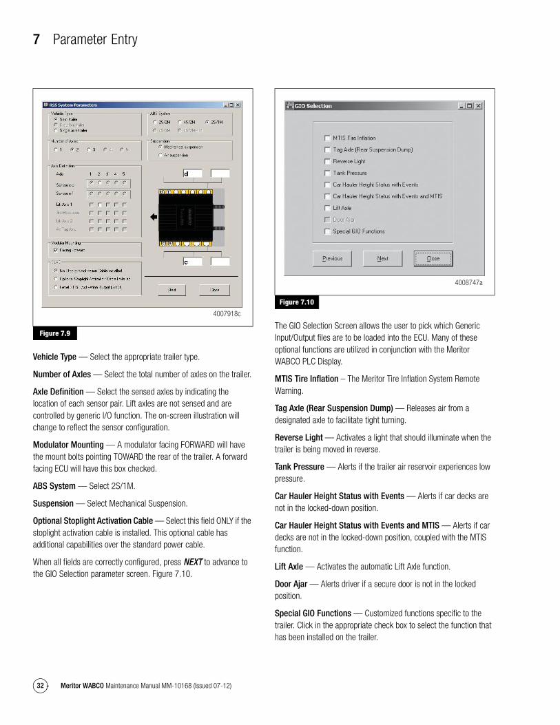
Figure 7.9
Vehicle Type — Select the appropriate trailer type.
Number of Axles — Select the total number of axles on the trailer.
Axle Definition — Select the sensed axles by indicating the location of each sensor pair. Lift axles are not sensed and are controlled by generic I/O function. The on-screen illustration will change to reflect the sensor configuration.
Modulator Mounting — A modulator facing FORWARD will have the mount bolts pointing TOWARD the rear of the trailer. A forward facing ECU will have this box checked.
ABS System — Select 2S/1M.
Suspension — Select Mechanical Suspension.
Optional Stoplight Activation Cable — Select this field ONLY if the stoplight activation cable is installed. This optional cable has additional capabilities over the standard power cable.
When all fields are correctly configured, press NEXT to advance to the GIO Selection parameter screen. Figure 7.10.
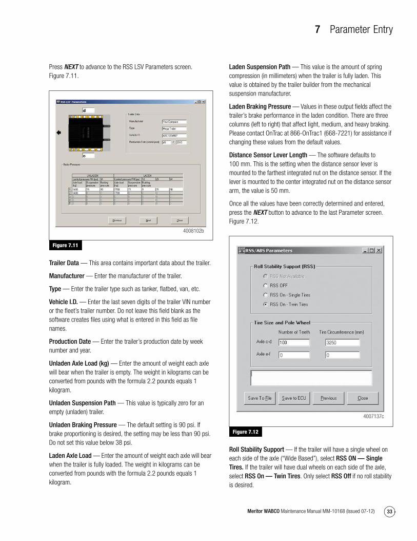
Figure 7.10
The GIO Selection Screen allows the user to pick which Generic Input/Output files are to be loaded into the ECU. Many of these optional functions are utilized in conjunction with the Meritor WABCO PLC Display.
MTIS Tire Inflation – The Meritor Tire Inflation System Remote Warning.
Tag Axle (Rear Suspension Dump) — Releases air from a designated axle to facilitate tight turning.
Reverse Light — Activates a light that should illuminate when the trailer is being moved in reverse.
Tank Pressure — Alerts if the trailer air reservoir experiences low pressure.
Car Hauler Height Status with Events — Alerts if car decks are not in the locked-down position.
Car Hauler Height Status with Events and MTIS — Alerts if car decks are not in the locked-down position, coupled with the MTIS function.
Lift Axle — Activates the automatic Lift Axle function.
Door Ajar — Alerts driver if a secure door is not in the locked position.
Special GIO Functions — Customized functions specific to the trailer. Click in the appropriate check box to select the function that has been installed on the trailer.
Figure 7.9
4007918c
Figure 7.10
4008747a
7 Parameter Entry
33Meritor WABCO Maintenance Manual MM-10168 (Issued 07-12)
Press NEXT to advance to the RSS LSV Parameters screen. Figure 7.11.
Figure 7.11
Trailer Data — This area contains important data about the trailer.
Manufacturer — Enter the manufacturer of the trailer.
Type — Enter the trailer type such as tanker, flatbed, van, etc.
Vehicle I.D. — Enter the last seven digits of the trailer VIN number or the fleet’s trailer number. Do not leave this field blank as the software creates files using what is entered in this field as file names.
Production Date — Enter the trailer’s production date by week number and year.
Unladen Axle Load (kg) — Enter the amount of weight each axle will bear when the trailer is empty. The weight in kilograms can be converted from pounds with the formula 2.2 pounds equals 1 kilogram.
Unladen Suspension Path — This value is typically zero for an empty (unladen) trailer.
Unladen Braking Pressure — The default setting is 90 psi. If brake proportioning is desired, the setting may be less than 90 psi. Do not set this value below 38 psi.
Laden Axle Load — Enter the amount of weight each axle will bear when the trailer is fully loaded. The weight in kilograms can be converted from pounds with the formula 2.2 pounds equals 1 kilogram.
Laden Suspension Path — This value is the amount of spring compression (in millimeters) when the trailer is fully laden. This value is obtained by the trailer builder from the mechanical suspension manufacturer.
Laden Braking Pressure — Values in these output fields affect the trailer’s brake performance in the laden condition. There are three columns (left to right) that affect light, medium, and heavy braking. Please contact OnTrac at 866-OnTrac1 (668-7221) for assistance if changing these values from the default values.
Distance Sensor Lever Length — The software defaults to 100 mm. This is the setting when the distance sensor lever is mounted to the farthest integrated nut on the distance sensor. If the lever is mounted to the center integrated nut on the distance sensor arm, the value is 50 mm.
Once all the values have been correctly determined and entered, press the NEXT button to advance to the last Parameter screen. Figure 7.12.
Figure 7.12
Roll Stability Support — If the trailer will have a single wheel on each side of the axle (“Wide Based”), select RSS ON — Single Tires. If the trailer will have dual wheels on each side of the axle, select RSS On — Twin Tires. Only select RSS Off if no roll stability is desired.
Figure 7.11
4008102bFigure 7.12
4007137c
3250
00

7 Parameter Entry
34 Meritor WABCO Maintenance Manual MM-10168 (Issued 07-12)
Tire Size and Pole Wheel — The Number of Teeth field is for the quantity of teeth on the tone ring. Nearly all tone rings have 100 teeth. The Tire Circumference is the dynamic tire radius of the tire in millimeters. The default setting of 3250 will be applicable to most tires, although an exact figure can be obtained from the tire’s manufacturer.
Once the parameters have been entered, press the Save to ECU button. The parameters are then saved to the ECU. You are now ready to proceed to the sign-off procedure.
8 Sensor Adjustment and Component Testing
35Meritor WABCO Maintenance Manual MM-10168 (Issued 07-12)
8 Sensor Adjustment and Component TestingHazard Alert MessagesRead and observe all Warning and Caution hazard alert messages in this publication. They provide information that can help prevent serious personal injury, damage to components, or both.
WARNINGTo prevent serious eye injury, always wear safe eye protection when you perform vehicle maintenance or service.
Park the vehicle on a level surface. Block the wheels to prevent the vehicle from moving. Support the vehicle with safety stands. Do not work under a vehicle supported only by jacks. Jacks can slip and fall over. Serious personal injury and damage to components can result.
The ABS is an electrical system. When you work on the ABS, take the same precautions that you must take with any electrical system to avoid serious personal injury. As with any electrical system, the danger of electrical shock or sparks exists that can ignite flammable substances. You must always disconnect the battery ground cable before working on the electrical system.
NOTE: Disconnect power from the ECU/Valve Assembly before you remove any components. Failure to disconnect power from the ECU can cause faults to be recorded and stored in ECU memory.
Testing
Test the Wheel Speed Sensors
NOTE: At initial installation, no gap must exist between the sensor and the tooth wheel.
NOTE: After you install a hub, always check that the sensor is adjusted correctly.
Operating the trailer can cause a gap to develop between the sensor and the tooth wheel. If the gap exceeds 0.040-inch, the system may not function correctly.
To adjust the sensor, twist and push the sensor through the sensor bracket as far as possible or until the sensor touches the tooth wheel. There is no need for a feeler gauge as the sensor will correctly gap itself when the wheel rotates.
Sensor Test Procedure
1. Disconnect power to the ECU/Valve Assembly.
2. Disconnect the sensor electrical connector from the ECU/Valve Assembly.
3. Connect the volt/ohm meter leads to the two wire rectangular terminals inside the disconnected connector.
4. When checking the resistance, the meter must read 900-2000 ohms.
5. Check and replace the sensor and cables as required.
6. Repeat Steps 1-5 for each sensor in the system.
Sensor Output Voltage Test
1. Disconnect power from the ECU/Valve Assembly.
2. Connect the AC volt/ohm meter leads to the sensor terminals inside the connector.
3. Rotate the corresponding wheel at a constant speed of one-half revolution per second.
4. The output voltage must be greater than 0.2 volts AC.
5. When there is no reading:
A. Trace the cable to verify that the cable connects to the wheel you turned.
B. Check that you turned the correct wheel.
C. Check that the system is wired correctly.
D. Check that the sensor touches the tooth wheel.
6. If the volt/ohm meter still indicates no reading or a low reading after following the above procedures, check and replace the component and cables as required.
7. Repeat Steps 1-5 for each sensor in the system.
Check ABS Functions� Meritor WABCO requires that you test a vehicle’s ABS after
a new installation and after you diagnose, repair and erase faults in the ABS.
� Perform end of line check using TOOLBOX™ Software.
End of Line TestingEnd of line testing is required on all RSS 1M installations. To run these tests, Meritor WABCO requires you use TOOLBOX™ Software.

8 Sensor Adjustment and Component Testing
36 Meritor WABCO Maintenance Manual MM-10168 (Issued 07-12)
TOOLBOX™ Software and general test procedures are included in this manual. If you are using a Pro-Link, refer to the operating manual for test instructions.
End of Line Testing Procedure Using TOOLBOX™ Software
NOTE: Refer to the Software Owner’s Manual, TP-99102, for instructions for running TOOLBOX™ Software.
1. Display the Trailer RSS Diagnostics Screen.
2. Verify power and air supply:
� Apply 12 volts DC to the blue wire (constant). Check the screen for correct voltage (10 to 14 volts). Constant power voltage is displayed in the Primary field.
� Power supply must have a 10 amp minimum.
� Apply 120 psi to the red (supply) line of the trailer’s air system. Be prepared to also apply 120 psi to the trailer’s blue (control) line when directed.
Putting the Trailer into Service
Sign-Off Procedure (End of Line Testing)
Once installed, the Meritor WABCO RSS 1M system must go through a sign-off procedure. This ensures that the system has been correctly installed and the pneumatic functions of the trailer are supporting the Roll Stability ABS.
In order to run the sign-off procedure, the trailer must be connected to 12 volt DC power (10 amp minimum), be connected to supply air (120 psi), have the capability to have control line air applied, and have the sensed axles raised off the ground.
The following procedure can be performed immediately if the replacement ECU has been installed in the default configuration (2S/1M, air suspension, ECU facing forward). If the ECU is installed in a non-default configuration, the ECU must be programmed before the sign-off procedure can be conducted. Refer to Section 8 for details.
For mechanical suspensions, the vehicle parameters must be changed from the default settings. Parameter Entry guidelines can be found in Section 7.
All RSS 1M ECUs have 1:1 air delivery default settings. If trailer specific load proportioning is desired, please contact Meritor WABCO at 866-OnTrac1 (668-7221) for assistance. If no proportioning is desired, air pressures are left at the default settings. The administration of these parameters is covered in the Parameter Entry guidelines in Section 8.
From the initial screen of the TOOLBOX™ Software, click on the RSS icon. Figure 8.1.
Figure 8.1
From the Main Screen, select Sign-Off from the pull-down menu bar. Then select Begin Sign-Off Procedure to begin the automated test procedure. Figure 8.2.
Figure 8.1
4010040a

8 Sensor Adjustment and Component Testing
37Meritor WABCO Maintenance Manual MM-10168 (Issued 07-12)
Figure 8.2
The Sensor Test
This portion of the sign-off will check the placement of the ABS wheel sensors. Ensure there is no pressure on the control (blue) line and that the trailer has all ABS sensed axles up off the ground. The following message will appear. Press OK after all safety precautions have been taken and release the blue air line to begin the test. Figure 8.3.
Figure 8.3
Lift all sensed wheels off the ground by jacking the appropriate axle. Rotate each wheel individually (in the order shown on the screen) and check the on-screen diagram to ensure correct sensor placement. Once the placement of all sensors has been correctly verified, press the Close button. Figure 8.4.
Figure 8.4
The Warning Lamp Test
This portion of the sign-off will ensure correct operation of the ABS warning lamp. The warning light will flash on and off. Wait for the test to end before pressing the Close button. Figure 8.5.
Figure 8.5
Figure 8.2
Figure 8.3
4007039d
0.0
0.0
0.0
0.0
4006945a
Figure 8.4
Figure 8.5
4009876a
4007042a

8 Sensor Adjustment and Component Testing
38 Meritor WABCO Maintenance Manual MM-10168 (Issued 07-12)
Distance Sensor Calibration
If the trailer has a spring suspension, the Mechanical Suspension Calibration screen will appear. Ensure that the trailer is now lowered so that all axles are fully on the ground. Confirm all conditions for calibration have been met before pressing Yes. Figure 8.6 and Figure 8.7.
Figure 8.6
Figure 8.6
4009899a

8 Sensor Adjustment and Component Testing
39Meritor WABCO Maintenance Manual MM-10168 (Issued 07-12)
Figure 8.7
The Distance Sensor arm must be parallel to the ground. The trailer should be on a flat, level surface and must be in the unladen (empty) state. If the displayed value is beyond the listed range, you will need to adjust the Distance Sensor. Once the value in the “Height Sensor” field no longer changes and is within the specified range, press the button labeled Calibrate Height Sensor.
A message appears if the calibration is successful. Press OK. Figure 8.8.
Figure 8.8
Successfully signing off the trailer will produce the confirmation screen and allow the tester the opportunity to save the results. Click on the Yes button and save the file in the appropriate data directory. Figure 8.9.
Figure 8.9
A message appears confirming the file has been saved and shows the location of the data. Figure 8.10.
Figure 8.10
Figure 8.7
Figure 8.8
4007079a
4007082a
Figure 8.9
Figure 8.10
4007139a
4007036a

8 Sensor Adjustment and Component Testing
40 Meritor WABCO Maintenance Manual MM-10168 (Issued 07-12)
OnTrac Customer Service CenterFor additional assistance, contact the OnTrac Customer Service Center at 866-OnTrac1 (668-7221).
Before calling the OnTrac Customer Service Center, be prepared to provide the following information:
1. The trailer’s original manufacturer and model year.
2. The SPECIFIC symptom or complaint.
3. What is the ABS blink code or TOOLBOX™ Software reading?
4. Have any resistance and/or voltage measurements been taken?
5. What is the result of visual inspection of connectors, harness and components?
6. When does the symptom occur (vehicle moving, fully loaded, etc.)?
7. Does the trailer have any unusual characteristics (for example, mismatched tires or larger than normal air consumption)?
8. What is the part number of the ECU/Valve Assembly? What is the system configuration?
By having the above information ready when you call, your customer service technician will be better equipped to assist you. Figure 8.11.
Figure 8.11
Figure 8.11
OnTrac Customer Service Center, 866-OnTrac1 (668-7221)
1003301a

Meritor WABCO Vehicle Control Systems2135 West Maple Road Printed in USATroy, MI 48084-7121866-OnTrac1 (668-7221) Copyright 2012 Issued 07-12meritorwabco.com Meritor, Inc. Maintenance Manual MM-10168 (16579)


