S enses require sensors. In the practice of robotics, the basic senses make do with the most basic of sensors: mechanical switches for detecting contact with objects, and photosensitive resistors and transistors for detecting the presence (or absence) of light. A robot can perform a remarkable amount of work with just the sense of touch and the gift of simple sight. In this month’s installment, you’ll learn about interfacing switches and photosensors to the Arduino, along with how to use the information these sensors provide to interactively command a robot’s motors. These are the fundamental building blocks of most any autonomous robot you build. Once you learn how to use these sensors to do your bidding, you can apply them in dozens of ways, for all kinds of robotic chores. Arduino Robotics: What We’ve Covered So Far This article builds upon previous installments in this series, which is all about the construction and use of the ArdBot (see Figure 1) — an inexpensive two-wheeled differentially-steered robot based on the popular Arduino Uno and compatible microcontrollers. If you’d like to follow along, be sure to check out the previous three episodes, so you’re familiar with the plot and characters. Part 1 introduced the ArdBot project, the Arduino, and basic programming fundamentals of this powerful controller. Part 2 detailed the construction of the ArdBot, using common materials such as plastic or aircraft grade plywood. Part 3 covered the Arduino in more depth, and examined the ins and outs of programming R/C servo motors with the Arduino. Making Robots With The Part 4 - Getting Feedback With Sensors By Gordon McComb FIGURE 1. The ArdBot robot uses an Arduino microcontroller and two R/C servo motors. Robots need information about the world around them, or they just stumble about looking stupid. Just like us humans, a robot uses senses to know when it’s run into something; when it’s light or dark; when it’s too hot or too cold; when it’s about to fall over; or when it’s found the way to the cheese at the center of a maze. SERVO 02.2011 67 Arduino
Transcript
Senses require sensors. In the practice of robotics,the basic senses make do with the most basic ofsensors: mechanical switches for detecting contactwith objects, and photosensitive resistors and
transistors for detecting the presence (or absence) of light.A robot can perform a remarkable amount of work withjust the sense of touch and the gift of simple sight.
In this month’s installment, you’ll learn aboutinterfacing switches and photosensors to the Arduino,along with how to use the information these sensorsprovide to interactively command a robot’s motors. Theseare the fundamental building blocks of most anyautonomous robot you build. Once you learn how to usethese sensors to do your bidding, you can apply them indozens of ways, for all kinds of robotic chores.
This article builds upon previous installments in thisseries, which is all about the construction and use of theArdBot (see Figure 1) — an inexpensive two-wheeleddifferentially-steered robot based on the popular ArduinoUno and compatible microcontrollers. If you’d like to followalong, be sure to check out the previous three episodes, soyou’re familiar with the plot and characters.
Part 1 introduced the ArdBot project, the Arduino, andbasic programming fundamentals of this powerfulcontroller.
Part 2 detailed the construction of the ArdBot, usingcommon materials such as plastic or aircraft grade plywood.
Part 3 covered the Arduino in more depth, andexamined the ins and outs of programming R/C servomotors with the Arduino.
Making RobotsWith The
Part 4 - Getting Feedback With Sensors
By Gordon McComb
FIGURE 1. TheArdBot robot uses an
Arduino microcontroller and two R/C servo motors.
Robots need information about the world around them, or they juststumble about looking stupid. Just like us humans, a robot uses senses
to know when it’s run into something; when it’s light or dark; when it’stoo hot or too cold; when it’s about to fall over; or when it’s found the
way to the cheese at the center of a maze.
SERVO 02.2011 67
Arduino
McComb - Arduino Robot Part 4 - Feb 11.qxd 12/24/2010 11:18 AM Page 67
68 SERVO 02.2011
What’s covered here applies to most any robot thatuses the Arduino microcontroller, and that runs on twomotors and rolls on wheels or tracks. You’re free to adaptthe techniques and programming code to whatever botsyou’re constructing. The ArdBot is an expandable platform,but it’s also a concept that represents the typical desktop-size robot.
The subject of sensors is pretty involved. There’s noway to cover all the interesting things in just one article.
So, next month you’ll learn about other kinds ofinexpensive sensors you can use with your ArdBot (or other robot).
Sensors — whether in humans or inrobots — are designed to produce areaction. What that reaction is dependson the nature of the sensation. Type andquantity matter. We interpret the feelingof a soft summer breeze as a goodsensation. Increase the amount of airpressure to hurricane force and decreasethe temperature to something below
freezing, and suddenly the same senses produce a highlynegative reaction.
Touch — also called tactile feedback — is a primitivereactive sense. The robot determines its environment bymaking physical contact; this contact is registered through avariety of touch sensors. What happens when contact ismade is entirely determined by the programming you applywithin your robot.
Most often, a collision with an object is a cause foralarm. So, the reaction of the robot is to stop what it’sdoing, and back away from the condition. In other cases,contact can mean your robot has found its home base, or
that it’s located an enemy bot and isabout to pound the living batteries outof it.
The lowly mechanical switch is themost common — and most simple —form of tactile (touch) feedbackmechanism. Just about anymomentary, spring-loaded switch willdo. When the robot makes contact,the switch closes, completing a circuit.
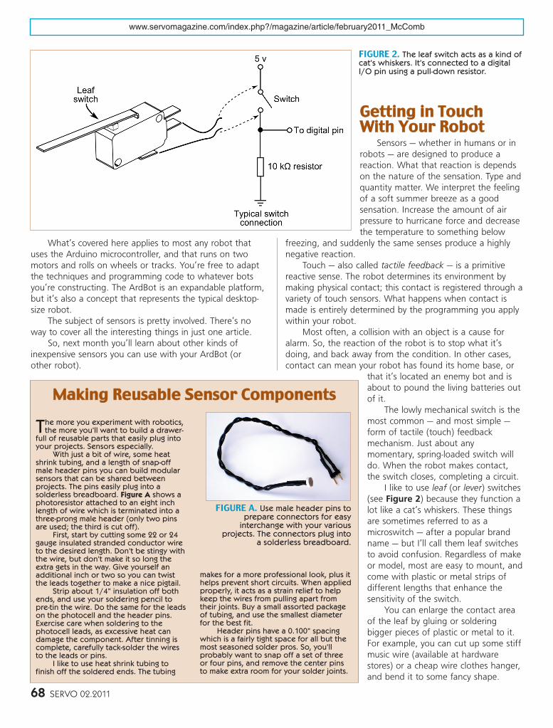
I like to use leaf (or lever) switches(see Figure 2) because they function alot like a cat’s whiskers. These thingsare sometimes referred to as amicroswitch — after a popular brandname — but I’ll call them leaf switchesto avoid confusion. Regardless of makeor model, most are easy to mount, andcome with plastic or metal strips ofdifferent lengths that enhance thesensitivity of the switch.
You can enlarge the contact areaof the leaf by gluing or solderingbigger pieces of plastic or metal to it.For example, you can cut up some stiffmusic wire (available at hardwarestores) or a cheap wire clothes hanger,and bend it to some fancy shape.
FIGURE 2. The leaf switch acts as a kind ofcat’s whiskers. It’s connected to a digitalI/O pin using a pull-down resistor.
The more you experiment with robotics,the more you’ll want to build a drawer-
full of reusable parts that easily plug intoyour projects. Sensors especially.
With just a bit of wire, some heatshrink tubing, and a length of snap-offmale header pins you can build modularsensors that can be shared betweenprojects. The pins easily plug into asolderless breadboard. Figure A shows aphotoresistor attached to an eight inchlength of wire which is terminated into athree-prong male header (only two pinsare used; the third is cut off).
First, start by cutting some 22 or 24gauge insulated stranded conductor wireto the desired length. Don’t be stingy withthe wire, but don’t make it so long theextra gets in the way. Give yourself anadditional inch or two so you can twistthe leads together to make a nice pigtail.
Strip about 1/4” insulation off bothends, and use your soldering pencil to pre-tin the wire. Do the same for the leadson the photocell and the header pins.Exercise care when soldering to thephotocell leads, as excessive heat candamage the component. After tinning iscomplete, carefully tack-solder the wiresto the leads or pins.
I like to use heat shrink tubing tofinish off the soldered ends. The tubing
makes for a more professional look, plus ithelps prevent short circuits. When appliedproperly, it acts as a strain relief to helpkeep the wires from pulling apart fromtheir joints. Buy a small assorted packageof tubing, and use the smallest diameterfor the best fit.
Header pins have a 0.100” spacingwhich is a fairly tight space for all but themost seasoned solder pros. So, you’llprobably want to snap off a set of threeor four pins, and remove the center pinsto make extra room for your solder joints.
FIGURE A. Use male header pins toprepare connectors for easy
interchange with your variousprojects. The connectors plug into
a solderless breadboard.
McComb - Arduino Robot Part 4 - Feb 11.qxd 12/24/2010 11:19 AM Page 68
Solder the end(s) to the leaf. Or, you can usethin pieces of wood, plastic, or metal. Just besure the weight of the extension doesn’taccidentally activate the switch. You don’twant false alarms.
The switch may be directly connected toa motor or, more commonly, it may beconnected to a microcontroller. A typicalwiring diagram for the switch is shown inFigure 2. The 10 kΩ pull-down resistor isthere to provide a consistent digital LOW (0 volts) outputfor the switch when there is no contact. When contact ismade, the switch closes, and the output of the switch goesHIGH — usually five volts, as shown here.
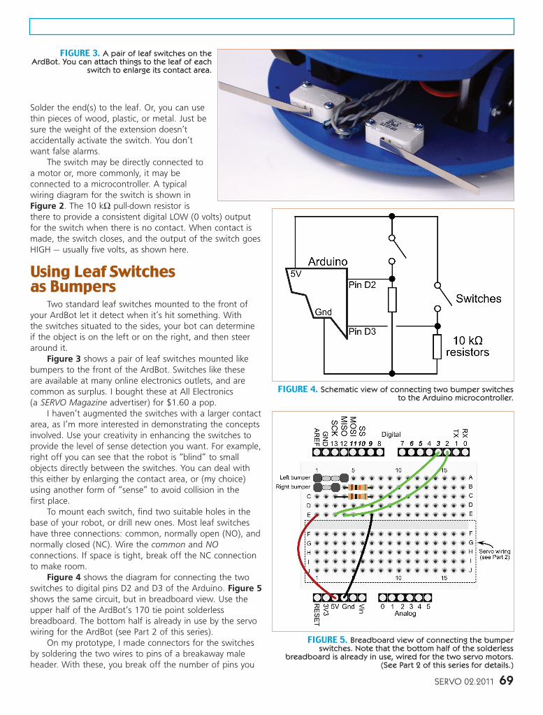
Two standard leaf switches mounted to the front ofyour ArdBot let it detect when it’s hit something. With the switches situated to the sides, your bot can determine if the object is on the left or on the right, and then steeraround it.
Figure 3 shows a pair of leaf switches mounted likebumpers to the front of the ArdBot. Switches like these are available at many online electronics outlets, and arecommon as surplus. I bought these at All Electronics (a SERVO Magazine advertiser) for $1.60 a pop.
I haven’t augmented the switches with a larger contactarea, as I’m more interested in demonstrating the conceptsinvolved. Use your creativity in enhancing the switches toprovide the level of sense detection you want. For example,right off you can see that the robot is “blind” to smallobjects directly between the switches. You can deal withthis either by enlarging the contact area, or (my choice)using another form of “sense” to avoid collision in the first place.
To mount each switch, find two suitable holes in thebase of your robot, or drill new ones. Most leaf switcheshave three connections: common, normally open (NO), andnormally closed (NC). Wire the common and NOconnections. If space is tight, break off the NC connectionto make room.
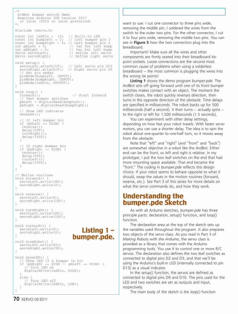
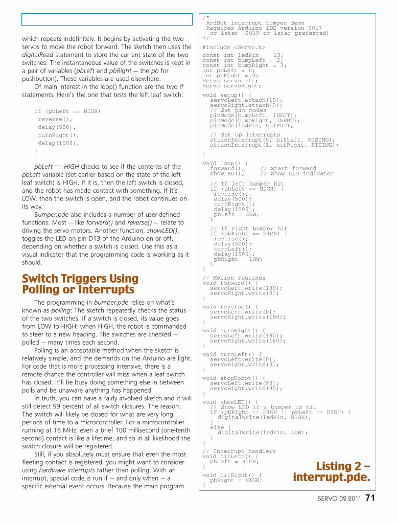
Figure 4 shows the diagram for connecting the twoswitches to digital pins D2 and D3 of the Arduino. Figure 5shows the same circuit, but in breadboard view. Use theupper half of the ArdBot’s 170 tie point solderlessbreadboard. The bottom half is already in use by the servowiring for the ArdBot (see Part 2 of this series).
On my prototype, I made connectors for the switchesby soldering the two wires to pins of a breakaway maleheader. With these, you break off the number of pins you
FIGURE 5. Breadboard view of connecting the bumperswitches. Note that the bottom half of the solderless
breadboard is already in use, wired for the two servo motors.(See Part 2 of this series for details.)
FIGURE 3. A pair of leaf switches on theArdBot. You can attach things to the leaf of each
switch to enlarge its contact area.
FIGURE 4. Schematic view of connecting two bumper switchesto the Arduino microcontroller.
SERVO 02.2011 69
McComb - Arduino Robot Part 4 - Feb 11.qxd 12/24/2010 11:19 AM Page 69
want to use. I cut one connector to three pins wide,removing the middle pin; I soldered the wires from theswitch to the outer two pins. For the other connector, I cutit to four pins wide, removing the middle two pins. You cansee in Figure 5 how the two connectors plug into thebreadboard.
Important! Make sure all the wires and othercomponents are firmly seated into their breadboard tie-point sockets. Loose connections are the second mostcommon cause of problems when using a solderlessbreadboard — the most common is plugging the wires intothe wrong tie points!
Listing 1 shows the demo program bumper.pde. TheArdBot sets off going forward until one of its front bumperswitches makes contact with an object. The moment theswitch closes, the robot quickly reverses direction, thenturns in the opposite direction of the obstacle. Time delaysare specified in milliseconds. The robot backs up for 500milliseconds (half a second). It then turns — actually spins —to the right or left for 1,500 milliseconds (1.5 seconds).
You can experiment with other delay settings,depending on how fast your robot travels. With faster servomotors, you can use a shorter delay. The idea is to spin therobot about one-quarter to one-half turn, so it moves awayfrom the obstacle.
Note that “left” and “right” (and “front” and “back”)are somewhat objective in a robot like the ArdBot. Eitherend can be the front, so left and right is relative. In myprototype, I put the two leaf switches on the end that hadmore mounting space available. That end became the“front.” The coding in bumper.pde reflects this designchoice. If your robot seems to behave opposite to what itshould, swap the values in the motion routines (forward,reverse, etc.). See Part 3 of this series for more details onwhat the servo commands do, and how they work.
As with all Arduino sketches, bumper.pde has threeprinciple parts: declaration, setup() function, and loop()function.
The declaration area at the top of the sketch sets upthe variables used throughout the program. It also preparestwo objects of the servo class. As you read in Part 3 ofMaking Robots with the Arduino, the servo class isprovided as a library that comes with the Arduinoprogramming tools. You use it to control one or more R/Cservos. The declaration also defines the two leaf switches asconnected to digital pins D2 and D3, and that we’ll beusing the Arduino’s built-in LED (internally connected to pinD13) as a visual indicator.
In the setup() function, the servos are defined asconnected to digital pins D9 and D10. The pins used for theLED and two switches are set as outputs and input,respectively.
The main body of the sketch is the loop() function
/*ArdBot bumper switch demo Requires Arduino IDE version 0017 or later (0019 or later preferred)
*/
#include <Servo.h>
const int ledPin = 13; // Built-in LEDconst int bumpLeft = 2; // Left bumper pin 2 const int bumpRight = 3; // Left bumper pin 3int pbLeft = 0; // Var for left bumpint pbRight = 0; // Var for left bumpServo servoLeft; // Define left servoServo servoRight; // Define right servo
void setup() servoLeft.attach(10); // Left servo pin D10servoRight.attach(9); // Right servo pin D9// Set pin modespinMode(bumpLeft, INPUT); pinMode(bumpRight, INPUT); pinMode(ledPin, OUTPUT);
void showLED() // Show LED if a bumper is hitif (pbRight == HIGH || pbLeft == HIGH)
// Turn LED ondigitalWrite(ledPin, HIGH);
else
// Turn LED offdigitalWrite(ledPin, LOW);
LLiissttiinngg 11 --bbuummppeerr..ppddee..
70 SERVO 02.2011
McComb - Arduino Robot Part 4 - Feb 11.qxd 12/24/2010 11:20 AM Page 70
which repeats indefinitely. It begins by activating the twoservos to move the robot forward. The sketch then uses thedigitalRead statement to store the current state of the twoswitches. The instantaneous value of the switches is kept ina pair of variables (pbLeft and pbRight — the pb forpushbutton). These variables are used elsewhere.
Of main interest in the loop() function are the two ifstatements. Here’s the one that tests the left leaf switch:
if (pbLeft == HIGH)
reverse();
delay(500);
turnRight();
delay(1500);
pbLeft == HIGH checks to see if the contents of thepbLeft variable (set earlier based on the state of the leftleaf switch) is HIGH. If it is, then the left switch is closed,and the robot has made contact with something. If it’sLOW, then the switch is open, and the robot continues onits way.
Bumper.pde also includes a number of user-definedfunctions. Most — like forward() and reverse() — relate todriving the servo motors. Another function, showLED(),toggles the LED on pin D13 of the Arduino on or off,depending on whether a switch is closed. Use this as avisual indicator that the programming code is working as itshould.
The programming in bumper.pde relies on what’sknown as polling: The sketch repeatedly checks the statusof the two switches. If a switch is closed, its value goesfrom LOW to HIGH; when HIGH, the robot is commandedto steer to a new heading. The switches are checked —polled — many times each second.
Polling is an acceptable method when the sketch isrelatively simple, and the demands on the Arduino are light.For code that is more processing intensive, there is aremote chance the controller will miss when a leaf switchhas closed. It’ll be busy doing something else in betweenpolls and be unaware anything has happened.
In truth, you can have a fairly involved sketch and it willstill detect 99 percent of all switch closures. The reason:The switch will likely be closed for what are very longperiods of time to a microcontroller. For a microcontrollerrunning at 16 MHz, even a brief 100 millisecond (one-tenthsecond) contact is like a lifetime, and so in all likelihood theswitch closure will be registered.
Still, if you absolutely must ensure that even the mostfleeting contact is registered, you might want to considerusing hardware interrupts rather than polling. With aninterrupt, special code is run if — and only when — aspecific external event occurs. Because the main program
/*ArdBot interrupt bumper demo Requires Arduino IDE version 0017 or later (0019 or later preferred)
*/
#include <Servo.h>
const int ledPin = 13;const int bumpLeft = 2; const int bumpRight = 3;int pbLeft = 0;int pbRight = 0;Servo servoLeft;Servo servoRight;
void showLED() // Show LED if a bumper is hitif (pbRight == HIGH || pbLeft == HIGH)
digitalWrite(ledPin, HIGH); else
digitalWrite(ledPin, LOW);
// Interrupt handlersvoid hitLeft()
pbLeft = HIGH;
void hitRight() pbRight = HIGH;
LLiissttiinngg 22 --iinntteerrrruupptt..ppddee..
SERVO 02.2011 71
McComb - Arduino Robot Part 4 - Feb 11.qxd 12/24/2010 11:20 AM Page 71
72 SERVO 02.2011
loop() doesn’t have to continually check the state of thepins, it frees up the controller to do other things. Reactiontime of an interrupt is measured in microsecond timing,even if the Arduino is busy doing something else. (Actually,this is not always true, depending on how other hardwareon the controller is being used. But any additional delay isusually minimal.)
The Arduino Uno supports two hardware interrupts(the Arduino Mega supports six) internally connected withinthe Arduino to digital pins D2 and D3. These are the pinsthat the leaf switches are already connected to, so the onlychange needed is in the software.
See Listing 2 for interrupt.pde. Here, the bumper.pdesketch has been revised to “listen” to a state change onboth of the hardware interrupts with the statements:
attachInterrupt(0, hitLeft, RISING);
attachInterrupt(1, hitRight, RISING);
Note that the interrupts are referred to as 0 and 1.These correspond to pins D2 and D3, respectively. Thelabels hitLeft and hitRight are the functions that are calledwhen the interrupt is triggered. Finally, RISING is a built-inconstant that tells the Arduino to trigger the interrupt on aLOW-to-HIGH signal transition. This type of transition occurswhen the switch closes.
Both hitLeft and hitRight set their corresponding “pb”variable to HIGH. The program then immediately exits theinterrupt handler. The next time the Arduino repeats itsloop(), it notices that a pushbutton is HIGH and performsthe needed obstacle avoidance maneuver. (Note also thatthe pushbutton value is manually set back to LOW, inanticipation of the next bump.)
You might be asking why the code to control theservos isn’t in the interrupt handlers. The reason is this: The
delay statement — which is used to steer the robot aroundan obstacle — is disabled while in an interrupt. In any case,it’s usually best not to place time-intensive functionalitywithin interrupt handlers.
TToo LLeett BBoouunnccee oorr DDeebboouunnccee??In a perfect world, mechanical switches would produce
clean, reliable digital signals for our microcontrollers. Wedon’t live in a perfect world; instead, we must suffersomething called switch bounce. Instead of a nice LOW-to-HIGH digital pulse when a switch closes, what we get arefive, 10, maybe even dozens of irregular glitches, all causedas the metal contacts in the switch settle into position. Allthis happens very quickly; usually in just a few milliseconds.
For some applications, it’s absolutely necessary todebounce the output of a switch. In debouncing, all theglitches are removed, providing the microcontroller withthat single sweet pulse we want. You can debounce withsome extra hardware: a capacitor and resistor create an RCnetwork that acts to delay the rise and fall of the switchsignal — that effectively removes the glitches. You can alsodo it in software, typically using delays so that themicrocontroller ignores all but the first signal transition.
Both the bumper.pde and interrupt.pde examples don’tdirectly use switch debounce. Software delays are alreadybuilt into the code, plus R/C servos are slow creatures anddon’t react fast enough for bounce to be a problem. Servosare commanded in 20 millisecond “frames” — that is, theiroperation is updated once every 20 milliseconds. Turns outthat’s about the worst-case duration of bounce glitchesfrom most switches. So, even with a switch bouncing alongmerrily, it has little or no effect on the operation of theservos.
Should you need to debounce your switch inputs,there’s a separate class library you can download
and use with the Arduino. The library is calledBounce, and it’s available from the mainArduino language reference pages. There’s alsoa Debounce code example that comes with theArduino programming IDE.
A few quick notes before moving on. Sofar, I’ve talked about the two switches in thefront of the robot, situated right and left. Feelfree to put switches anywhere you want. Youmight instead have a front and back switch, ora bunch of switches all around the periphery ofthe robot.
If you use more than two switches, you’llhave to rely on polling, as there are only twopins that support hardware interrupts (whenusing the Arduino Uno). If you use more thanfour or five switches, you may want to use a
If you’d like to build the ArdBot,be sure to start with theNovember ‘10 issue of SERVOMagazine for Part 1 of this series.Also check out the followingsources for parts:
Example code and more:
Arduinowww.arduino.cc
Fritzingwww.fritzing.org
Prefabricated ArdBot bodypieces with all constructionhardware:
Budget Roboticswww.budgetrobotics.com
Partial list of Arduino resellers:
AdaFruitwww.adafruit.com
HVW Techwww.hvwtech.com
Jamecowww.jameco.com
Pololuwww.pololu.com
Robotshopwww.robotshop.com
Solarboticswww.solarbotics.com
Sparkfunwww.sparkfun.com
SSoouurrcceess
McComb - Arduino Robot Part 4 - Feb 11.qxd 12/28/2010 8:41 AM Page 72
parallel-to-serial (PISO) shift register chip, such as the74HC165 or CD4021. These are integrated circuits that takeeight parallel inputs and provide a serial data output thatcan be read by the Arduino. Assuming eight switches, thePISO reduces the number of required I/O pins from eight tothree. There’s a code example for how to do this atarduino.cc/en/Tutorial/ShiftIn.
Next to tactile feedback, reacting to light is the mostcommon robotic sense. In lieu of actual vision, the robotuses electronic components such as photoresistors andphototransistors that are sensitive to light. Your bot mayreact to the simple absence or presence of light, or it maybe able to measure the brightness, color, or otherqualitative aspect of the light.
Photoresistors — also called photocells, light dependentresistors, or CdS (for cadmium sulfide) cells — are perhapsthe easiest to use as simple light sensors. The photocell is aresistor whose value changes depending on the amount oflight that strikes its sensing surface. In darkness, thephotocell has a high resistance, typically in theneighborhood of 100 kΩ to over one megohm, dependingon the component. The resistance falls as more light strikesthe cell. In high brightness, the resistance may be as low as1 kΩ to 10 kΩ.
The exact dark/light resistance values differ dependingon the component, and even among photocells of the samemake and model. Typical value tolerance is 10 to 20percent. You can purchase photocells new, but they’recommon finds in the surplus market. Get a variety pack,and use your multimeter to “grade” each one. Cracks andother injury spell doom to a photocell; air and moisturedegrade the sensing surface, rendering it useless. Toss anythat don’t react properly to a nearby desk lamp.
Being a resistor, you can convert the output of aphotocell to a varying voltage merely by connecting anotherresistor to it in series, as shown in Figure 6. The value ofthe series resistor depends on the dark/light resistancerange of the photocell, and how you want to use it. Thecells I used had a dark resistance of about 40 kΩ and alight resistance of 30 ohms. In average room brightness,the cells had 10 kΩ resistors, so I selected a 10 kΩ seriesresistor.
The voltage at the point between the photocell andseries resistor is a ratio of the two resistance values. Withthe two resistances equal, the divided voltage betweenthem is one-half of the supply voltage; in the case of fivevolts in average room light, the output voltage is 2.5 volts.
FIGURE 6. By connecting another resistor in series with aphotoresistor, the output is converted to a varying voltage.
In this particular arrangement, the voltage increases under stronger light.
void loop() // Read analog pin A0 and display value// on Serial Monitor windowcds = analogRead(A0);Serial.println(cds, DEC);delay (200);
FIGURE 7. Schematic view of connecting two photocells to theArduino microcontroller.
McComb - Arduino Robot Part 4 - Feb 11.qxd 12/24/2010 11:20 AM Page 73
The voltage decreases in darkness and increases as morelight strikes the photocell.
You will need to experiment with the series resistor todetermine its best value, based on the specific photocellsyou use. You might want to try a 50 kΩ or 100 kΩpotentiometer in place of a fixed resistor, allowing you tofine-tune the series resistance as needed.
Listing 3 shows simplecds.pde, a basic sketch thattests the operation of the photocell. Wire the photocell asshown in Figure 6 and connect the output to analog pin
A0 of your Arduino. Compile and upload the sketch, thenopen the serial monitor window. You’ll see a series ofnumbers; they correspond to the output voltage of thesensor converted to a 10-bit (0 to 1023) numeric value. Youshould get a low number when all light to the photocell isblocked, and a higher number under full illumination.
SStteeeerriinngg YYoouurr RRoobboott WWiitthh aa FFllaasshhlliigghhtt
By using two photocells mounted on each side of yourArdBot, you can literally steer it by flashlight. Under justroom light, the robot is set to stop, waiting for yourcommand. Aim the flashlight so that light falls more or lessequally on both photocells, and the robot will moveforward. When the light levels aren’t equal, the robot willturn toward the photocell that has more light falling on it.
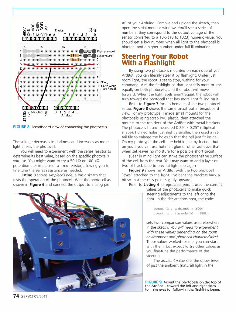
Refer to Figure 7 for a schematic of the two-photocellsetup. Figure 8 shows the same circuit but in breadboardview. For my prototype, I made small mounts for thephotocells using scrap PVC plastic, then attached themounts to the top deck of the ArdBot with metal brackets.The photocells I used measured 0.29” x 0.25” (ellipticalshape). I drilled holes just slightly smaller, then used a rat-tail file to enlarge the holes so that the cell just fit inside.On my prototype, the cells are held in just by friction, buton yours you can use hot-melt glue or other adhesive thatwhen set leaves no moisture for a possible short circuit.
(Bear in mind light can strike the photosensitive surfaceof the cell from the rear. You may want to add a layer ortwo of black tape to prevent light spoilage.)
Figure 9 shows my ArdBot with the two photocell“eyes” attached to the front. I’ve bent the brackets back abit so that the cells point slightly upward.
Refer to Listing 4 for lightsteer.pde. It uses the currentvalues of the photocells to make quicksteering adjustments to the left or to theright. In the declarations area, the code:
const int ambient = 600;
const int threshold = 800;
sets two comparison values used elsewherein the sketch. You will need to experimentwith these values depending on the roomenvironment and photocell characteristics!These values worked for me; you can startwith them, but expect to try other values asyou fine-tune the performance of thesteering.
The ambient value sets the upper levelof just the ambient (natural) light in the
FIGURE 8. Breadboard view of connecting the photocells.
FIGURE 9. Mount the photocells on the top ofthe ArdBot — toward the left and right sides —to make eyes for following the flashlight beam.
74 SERVO 02.2011
McComb - Arduino Robot Part 4 - Feb 11.qxd 12/24/2010 11:21 AM Page 74
room. This is the amount of light that hits thephotocells under normal lighting conditions. For me,the ambient light value was about 520 to 530, so Imade it a little higher (600) for extra headroom.
The threshold value sets the lower level of thelight beamed from your flashlight. I set the value at800 based on using a nine-LED flashlight (with freshbatteries), 1-2 feet away from the robot. For bestresults, use a bright flashlight near the robot — thefarther away you get, the less light that falls on thephotocells.
MMoorree LLiigghhtt TTrriicckkssJust by switching around some of the code you
can have your robot run away from you rather thantry to follow you. Or, by placing colored gel filtersover the photocells and using a color LED flashlight(blue and green are popular), your robot can morereadily discriminate between light to follow and lightto ignore.
You might also add one or two “room light”sensors that aren’t in the direct line-of-sight of theflashlight beam. These could be used to set theambient light level of the room.
Small lenses over the photocells help to focus theflashlight beam, improving steering performance andhelping the bot reject any light not directly to thefront.
These are just some of the things you can do togive your ArdBot (or other Arduino-powered bot) thegift of sight. Feel free to experiment. Photocells andother light sensitive components are inexpensive, andchanging the code in an Arduino sketch is absolutelyfree.
CCoommiinngg UUpp ......In our next installment, you’ll discover even more
senses you can provide, including ultrasonic sound formeasuring distances to objects, and infrared light todetermine the proximity of nasty things that are in the way.
You’ll also read about ways for your robot to scanthe room to soak up its environment, rather than justsee life through a narrow tunnel in front of it. Excitingstuff (at least for your ArdBot), so don’t miss it! SV