58
Copyright © 2006-2009 AudioNote Kits www.AudioNoteKits.com [email protected] Page 1 Manual Version 1.1 - August 2009

Copyright © 2006-2009 AudioNote Kits www.AudioNoteKits.com [email protected]
Page 1
Manual Version 1.1 - August 2009

Copyright © 2006-2009 AudioNote Kits www.AudioNoteKits.com [email protected]
Page 2
Table of Contents Section1: Introduction ............................................................................................................................................................. 3 Component Placement Breakdown..................................................................................................................................... 4 Electrical Safety Warning .................................................................................................................................................... 5
Section 2: First Steps .............................................................................................................................................................. 6 Installing the feet ................................................................................................................................................................. 6 IEC Section Installation ....................................................................................................................................................... 7 Mains Transformer Installation ............................................................................................................................................ 7 IEC Section.......................................................................................................................................................................... 8 Preparing the Secondary leads ......................................................................................................................................... 11
Section 3: Power Supply Board Construction ....................................................................................................................... 12 Installing the Components ................................................................................................................................................. 12
Section 4: Choke Installation and HT Wiring ........................................................................................................................ 14 Section 5: ECF80 Driver Board Construction ....................................................................................................................... 16 Parts List............................................................................................................................................................................ 17 Installing the Spacers and Valve Base.............................................................................................................................. 18 Installing the Resistors ...................................................................................................................................................... 19 Installing the Capacitors .................................................................................................................................................... 20
Section 6: EL34 Hardwired Section ...................................................................................................................................... 22 Parts List............................................................................................................................................................................ 23 Assembly ........................................................................................................................................................................... 23
Section 7: Layout Recap ....................................................................................................................................................... 30 Section 8: EL34 Board Filament Hook-Up ............................................................................................................................ 31 Section 9: EL34 Board To Output Transformer Wiring ......................................................................................................... 33 Section 10: HT and GND Connections to EL34 Board ......................................................................................................... 35 Section 11: Speaker Post Connections ................................................................................................................................ 37 Section 12: Driver Board Filament Hook-up ......................................................................................................................... 41 Section 13: ECF80 to EL34 Board Interconnections ............................................................................................................ 43 Section 14: RCA Connections and Final Earth ..................................................................................................................... 46 Section 15: Powering On and Testing .................................................................................................................................. 49 Power On Procedure ......................................................................................................................................................... 49
Appendix ............................................................................................................................................................................... 50 Resistor Color Code Reference......................................................................................................................................... 51 Mains Transformer Windings Diagram.............................................................................................................................. 52 Power Supply Board Schematic........................................................................................................................................ 53 Driver Board Schematic..................................................................................................................................................... 54 Output Board Schematic ................................................................................................................................................... 55 Output Section Hardwiring Diagram.................................................................................................................................. 56 General Wiring Diagram .................................................................................................................................................... 57 Full Schematic ................................................................................................................................................................... 58

Copyright © 2006-2009 AudioNote Kits www.AudioNoteKits.com [email protected]
Page 3
Section1: Introduction
Thanks for purchasing the AudioNote L4 Series EL34 Push-Pull Power Amplifier. Our goal is to provide you with the highest quality Kit that you will build from scratch with these instructions. If you have any questions or comments during the build feel free to contact us and we would be happy to help out. You will need a soldering iron or soldering station with a sponge along with wire strippers and a Phillips screwdriver. A nut driver or a pair of pliers would be useful as well. We have divided the manual up into a series of step-by-step instructions for the successful build and debug of the kit. There are several places during the build that you will perform tests and/or checks to make sure that you are on track. This way when you complete the kit you will know that all the major sections are working. You will find a number of component bags supplied with your kit. These bags will be referred to throughout this manual. Here are some tips from working with many kit builders over the last few years: � Perform your work in small manageable chunks. Do not be in a hurry to listen to your finished kit. � Savor the build experience. Here’s a chance to really get to know your audio kit that will give you many hours of
enjoyment. � Better to work on a section and then spend the time to check over the section rather than just carrying on. � The kit building experience should be a pleasant one so find a place that you can build the kit with relative peace
so you can concentrate on the instructions. � If you plan for a long build stretch on a Saturday afternoon for example then take plenty of breaks with constant
re-checks of your work. Whilst working through this manual, please feel free to give us your feedback and any other information that may allow us to improve the build experience.

Copyright © 2006-2009 AudioNote Kits www.AudioNoteKits.com [email protected]
Page 4
Component Placement Breakdown
Copyright © 2006-2009 AudioNote Kits www.AudioNoteKits.com [email protected]
Page 5
Electrical Safety Warning
There are sufficient voltages in this kit to give you a very nasty and harmful shock so be careful when powering on, debugging, and probing around. Please be aware of proper electrical safety. Please contact AudioNote Kits via phone or email to discuss any precautions necessary when building the kit if you feel unsure about what you are doing at any stage of the build.

Copyright © 2006-2009 AudioNote Kits www.AudioNoteKits.com [email protected]
Page 6
Section 2: First Steps
In this beginning section we will start by installing the 4 feet then we will install the Mains transformer and wire up the IEC section.
Installing the feet Our first task is to install the 4 rubber feet into the holes in the 4 corners of the chassis using the provided hardware in the “Feet” Bag (found in the big Hardware bag). Use the M4 screw along with the big washer on the outside of the foot and then a M4 nut and M4 black serrated washer against the chassis on the inside of the chassis!
Might be handy to use an M4 nut driver or something similar to tighten the nuts for the feet on the inside of the chassis as shown below.

Copyright © 2006-2009 AudioNote Kits www.AudioNoteKits.com [email protected]
Page 7
IEC Section Installation
Let’s install the input AC receptacle and rocker switch known as the IEC socket & Rocker in the rear of the chassis. Shown opposite is the rocker switch slot above the fitted IEC socket.
Here you can see the correct installation of the IEC plug in the rear of the chassis along with the Rocker switch.
Mains Transformer Installation
2 rubber strips are used to isolate the mains transformer from the chassis. Lay down the two rubber strips so that they are over the correct holes in the chassis (these holes are about 100mm apart).
Copyright © 2006-2009 AudioNote Kits www.AudioNoteKits.com [email protected]
Page 8
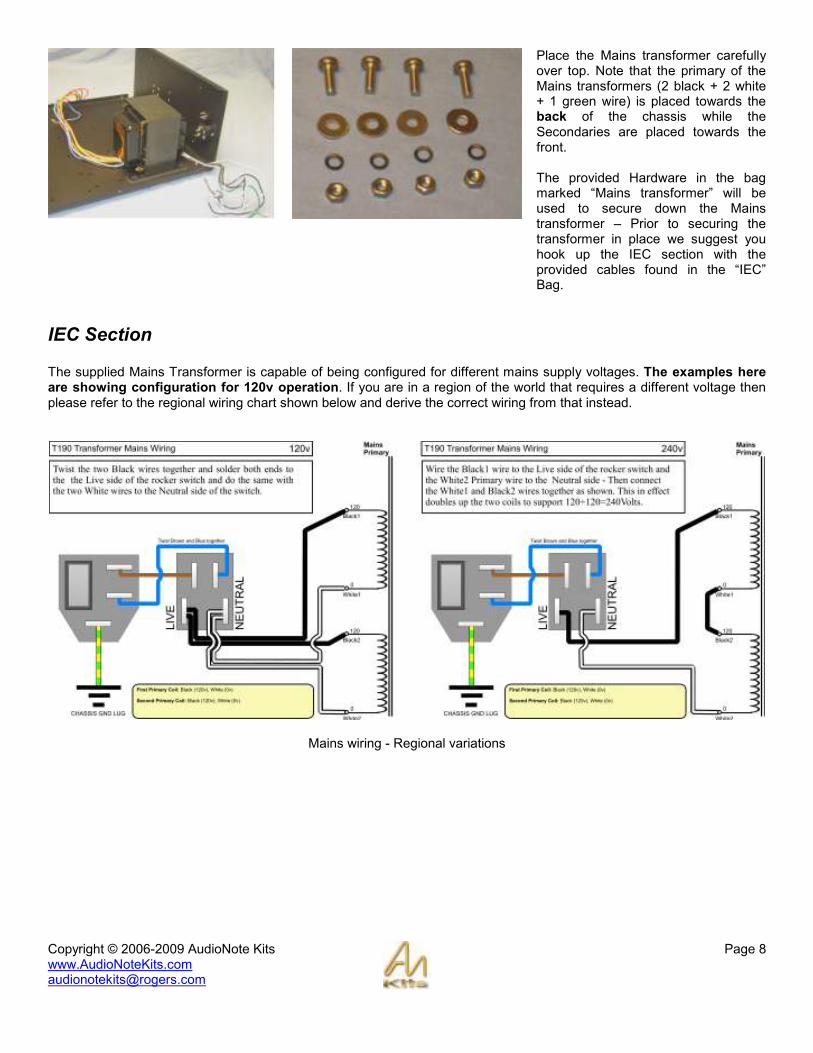
Place the Mains transformer carefully over top. Note that the primary of the Mains transformers (2 black + 2 white + 1 green wire) is placed towards the back of the chassis while the Secondaries are placed towards the front. The provided Hardware in the bag marked “Mains transformer” will be used to secure down the Mains transformer – Prior to securing the transformer in place we suggest you hook up the IEC section with the provided cables found in the “IEC” Bag.
IEC Section The supplied Mains Transformer is capable of being configured for different mains supply voltages. The examples here are showing configuration for 120v operation. If you are in a region of the world that requires a different voltage then please refer to the regional wiring chart shown below and derive the correct wiring from that instead.
Mains wiring - Regional variations

Copyright © 2006-2009 AudioNote Kits www.AudioNoteKits.com [email protected]
Page 9
Remember, the following example shows how to wire for 120v operation only.
If you live in a 120V AC world voltage then we will twist the black wires together as shown as well as twisting the white wires. We will also be working with the green screen wire. * Applies to 120v operation only.
The next step is trim the wires lengths once they have been twisted such that the length would reach to the top of the chassis (approx 7 or 8 inches). * Applies to 120v operation only.
Take both black twisted wires and strip about ½ inch of insulation – then twist the ends together – then TIN this end by applying solder to it to make sure that it is nicely formed. Then place a blue CRIMP on the end of the wire. Here’s the tricky part – add solder so that the TINNed end of wire adheres to the crimp – you will probably need to add a surprising amount of solder to make sure there is a very good connection along with quite a bit of heat. Once the crimp has been added then you can place the heat shrink over the exposed metal end of the crimp and apply your heat gun. REPEAT for the White twisted wires. * Applies to 120v operation only.

Copyright © 2006-2009 AudioNote Kits www.AudioNoteKits.com [email protected]
Page 10
Now let’s deal with the green wire coming out of the Mains Primary. This is the ground lead that we will be attaching to chassis ground. Strip the wire and tin it and then solder the ground lug to it.
This is where you will attach the earth wire to. You will secure it using an M4 16mm pan screw from under the chassis and use a nut to secure the ground lug from the Mains transformer. Note that the mains input earth will also be joining it shortly.
In order to complete the IEC wiring, you will be using 2 pre-terminated cables. The first one is the earth cable shown here. This connects to the IEC mains socket’s earth lug, which is in turn connected to the chassis earth lug (discussed previously).
Now use the twisted pair cable (shown opposite) to complete the wiring between the mains input socket and the mains switch - refer to the wiring diagram shown previously. You will have to apply some pressure to position the crimps correctly onto the lugs.

Copyright © 2006-2009 AudioNote Kits www.AudioNoteKits.com [email protected]
Page 11
The IEC section is now complete. The picture opposite shows the completed wiring for 120v operation. * Applies to 120v operation only.
Preparing the Secondary leads
Pull out your insert sheet showing the Mains transformer windings for the secondary. The first step is to twist the wires according to the windings:
• Blue & Yellow
• Red & Blue/White
• Brown & Black/Green
• Orange & Violet & Orange/White (Braid these wires – you may have to ask your wife!)
We will be using these twisted wires later – lets move on to the Power Supply Board.
Copyright © 2006-2009 AudioNote Kits www.AudioNoteKits.com [email protected]
Page 12
Section 3: Power Supply Board Construction
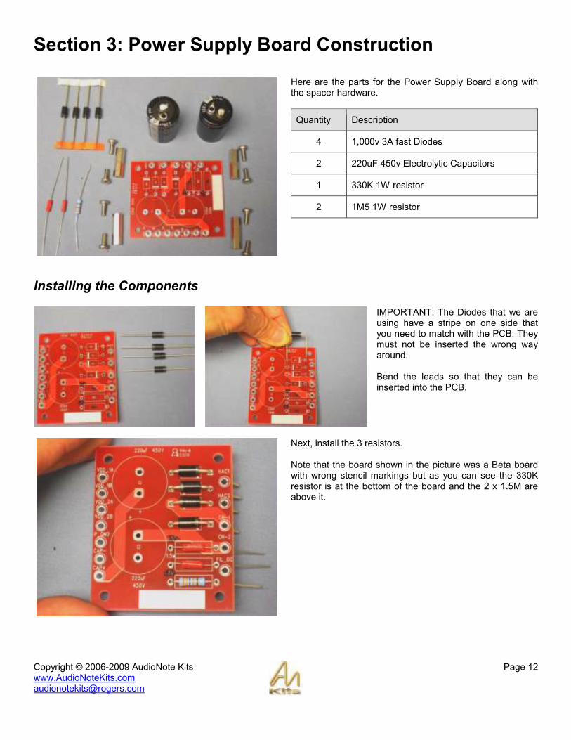
Here are the parts for the Power Supply Board along with the spacer hardware.
Quantity Description
4 1,000v 3A fast Diodes
2 220uF 450v Electrolytic Capacitors
1 330K 1W resistor
2 1M5 1W resistor
Installing the Components
IMPORTANT: The Diodes that we are using have a stripe on one side that you need to match with the PCB. They must not be inserted the wrong way around. Bend the leads so that they can be inserted into the PCB.
Next, install the 3 resistors. Note that the board shown in the picture was a Beta board with wrong stencil markings but as you can see the 330K resistor is at the bottom of the board and the 2 x 1.5M are above it.

Copyright © 2006-2009 AudioNote Kits www.AudioNoteKits.com [email protected]
Page 13
The next job is to install the Electrolytic Capacitors.
Quick Lesson on Electrolytic Capacitors These capacitors have a Positive and Negative side to them and need to be installed correctly or they will BLOW up! The Stripe on the side of the capacitor can designates the NEGATIVE side. You will also see the + sign marked on the PCB denoting the positive side
Here you can see the capacitor being correctly installed in the board.
Here you can see the Power Supply Board correctly populated. Check over the board for correct positioning and polarities before finally soldering the components in place.
Finally, you can install the spacers on each corner of the board and position the board into its correct location in the chassis.

Copyright © 2006-2009 AudioNote Kits www.AudioNoteKits.com [email protected]
Page 14
Section 4: Choke Installation and HT Wiring
Here is how the choke and the Power supply board will be positioned in the chassis. You will want to bring the Mains transformer secondary leads through on this side of the chassis and position the twisted filament wires from the secondary windings going the other way into the amplifier. Use the supplied hardware (M3 screws and nuts) to secure the choke into position.
Trim and tin the Choke wires (yellow and black) so that you can connect them to the power supply board. Insert them underneath the board if you like and apply solder from the top of the board – plenty of solder will be used and then you can trim the extra tinned wire poking through the board. Connect the yellow and black wires from the Choke into holes CH-1 and CH-2 – it does not matter which wire goes to which hole.
Now lets take the High Voltage wires (Yellow and Blue) and trim to length. Strip the end of the wires and tin. Connect to HAC1 (High Voltage AC 1) and HAC2 (High Voltage AC 2).

Copyright © 2006-2009 AudioNote Kits www.AudioNoteKits.com [email protected]
Page 15
Finally, bring the triple braided wire down the length of the chassis for later use. Now we can move onto the next stage of the build.

Copyright © 2006-2009 AudioNote Kits www.AudioNoteKits.com [email protected]
Page 16
Section 5: ECF80 Driver Board Construction
In this section we will be building the first of the 2 Driver Boards, which contain the ECF80 tube. See the Appendix for the schematic for this board.
The build of this board is quite straightforward and shouldn’t pose any problems. Just make sure that the three electrolytic capacitors are inserted the correct way around - observing correct polarity. SPECIAL NOTE: R12 and R13 have been moved from this board to the Output Board. Therefore, you should replace these resistors with wire links!

Copyright © 2006-2009 AudioNote Kits www.AudioNoteKits.com [email protected]
Page 17
Parts List
Quantity Value Designator Description
1 100R R6 1W
1 470R R5 1W
1 1K R2 1W
1 2K2 R15 1W
2 10K Wire links
R12, R13 1W The resistors that used to be here have been moved to the Output Board for performance reasons. Wire links should now be used here in their place.
1 22K R9 1W
3 33K R7, R8, R14 1W
1 100K R1 1W
1 330K R3 1W
2 470K R10, R11 1W
1 1.8K R16
Resistors
2 51K R4a, R4b
1 470uF 16v C2 ECF80 cathode
1 10uF 450v C1 ECF80
1 100uF 450v C3 HT / GND
2 .22uF 630v Input to EL34
1 100pF 630v C6 ECF80 input
Capacitors
1 820pF C7
Copyright © 2006-2009 AudioNote Kits www.AudioNoteKits.com [email protected]
Page 18
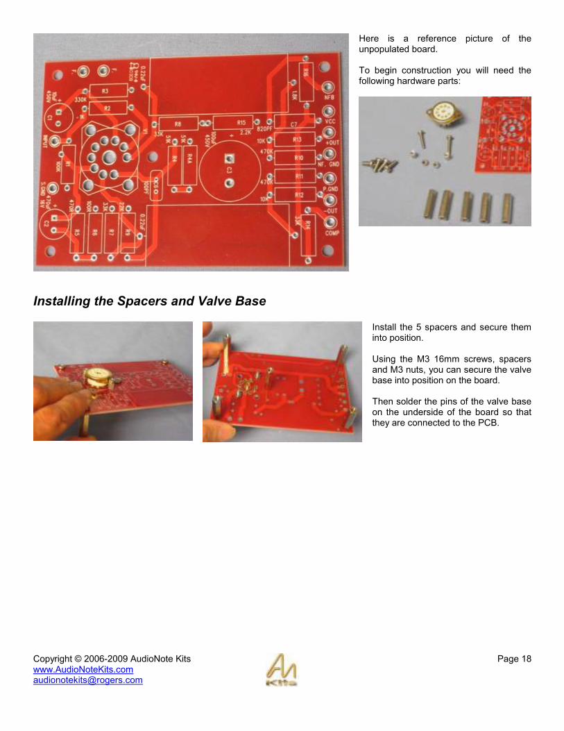
Here is a reference picture of the unpopulated board. To begin construction you will need the following hardware parts:
Installing the Spacers and Valve Base
Install the 5 spacers and secure them into position. Using the M3 16mm screws, spacers and M3 nuts, you can secure the valve base into position on the board. Then solder the pins of the valve base on the underside of the board so that they are connected to the PCB.

Copyright © 2006-2009 AudioNote Kits www.AudioNoteKits.com [email protected]
Page 19
Installing the Resistors
Install the resistors into their correct positions on the board. Refer to the parts list on the previous page. It’s also a good idea to use an OHM meter and refer to the color code chart for inserting the correct resistors into position. NOTE: In the picture opposite we have also installed the 2 x .22 film caps into position – you can do this later in the capacitor section. For now just concentrate on the resistors. NOTE: R12 and R13 should be replaced with wire links as these resistors have been relocated to the Output board for performance reasons.
You will want to bend the legs to fit into position and then solder on the underside of the board. Here you can see the underside of the board – good idea to do a double check on your resistor values once they are inserted prior to soldering into position – check with the schematic and the color code chart to make sure it all makes sense!
These two pictures show the underside of the board with the valve base soldered into position and the resistor leads clipped!
Copyright © 2006-2009 AudioNote Kits www.AudioNoteKits.com [email protected]
Page 20
Installing the Capacitors
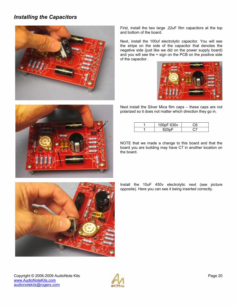
First, install the two large .22uF film capacitors at the top and bottom of the board. Next, install the 100uf electrolytic capacitor. You will see the stripe on the side of the capacitor that denotes the negative side (just like we did on the power supply board) and you will see the + sign on the PCB on the positive side of the capacitor.
Next install the Silver Mica film caps – these caps are not polarized so it does not matter which direction they go in.
1 100pF 630v C6
1 820pF C7
NOTE that we made a change to this board and that the board you are building may have C7 in another location on the board.
Install the 10uF 450v electrolytic next (see picture opposite). Here you can see it being inserted correctly.
Copyright © 2006-2009 AudioNote Kits www.AudioNoteKits.com [email protected]
Page 21
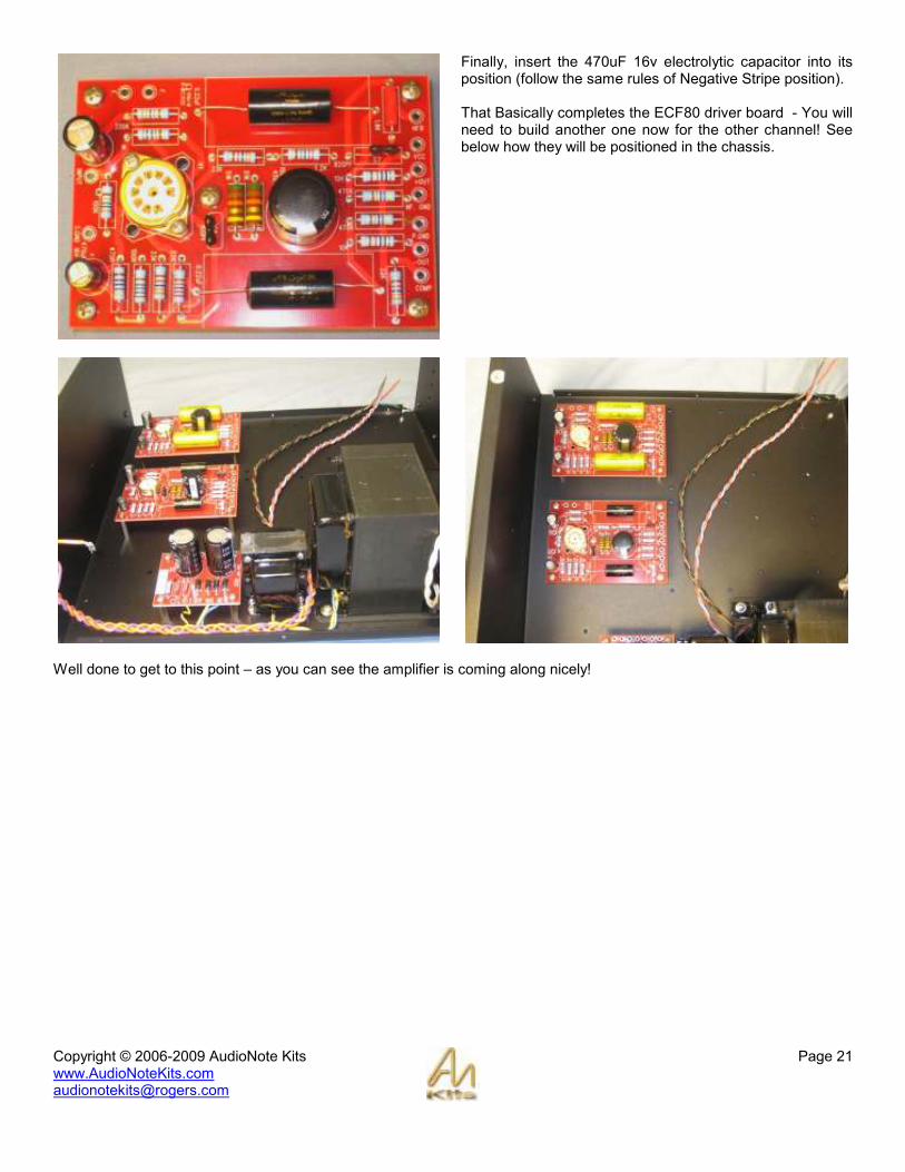
Finally, insert the 470uF 16v electrolytic capacitor into its position (follow the same rules of Negative Stripe position). That Basically completes the ECF80 driver board - You will need to build another one now for the other channel! See below how they will be positioned in the chassis.
Well done to get to this point – as you can see the amplifier is coming along nicely!

Copyright © 2006-2009 AudioNote Kits www.AudioNoteKits.com [email protected]
Page 22
Section 6: EL34 Hardwired Section
In this section we will be building the hardwired section on the aluminum plates where the EL34’s reside – It’s a challenging little section but also fun and rewarding. Here is what It will look like from the topside. The picture below shows what the boards will be like from underside:
NOTE: Since these pictures were taken, we have relocated 2x 10K resistors from the Driver Board to here. Therefore the White wires that can be seen above are now replaced with these relocated resistors.
Copyright © 2006-2009 AudioNote Kits www.AudioNoteKits.com [email protected]
Page 23
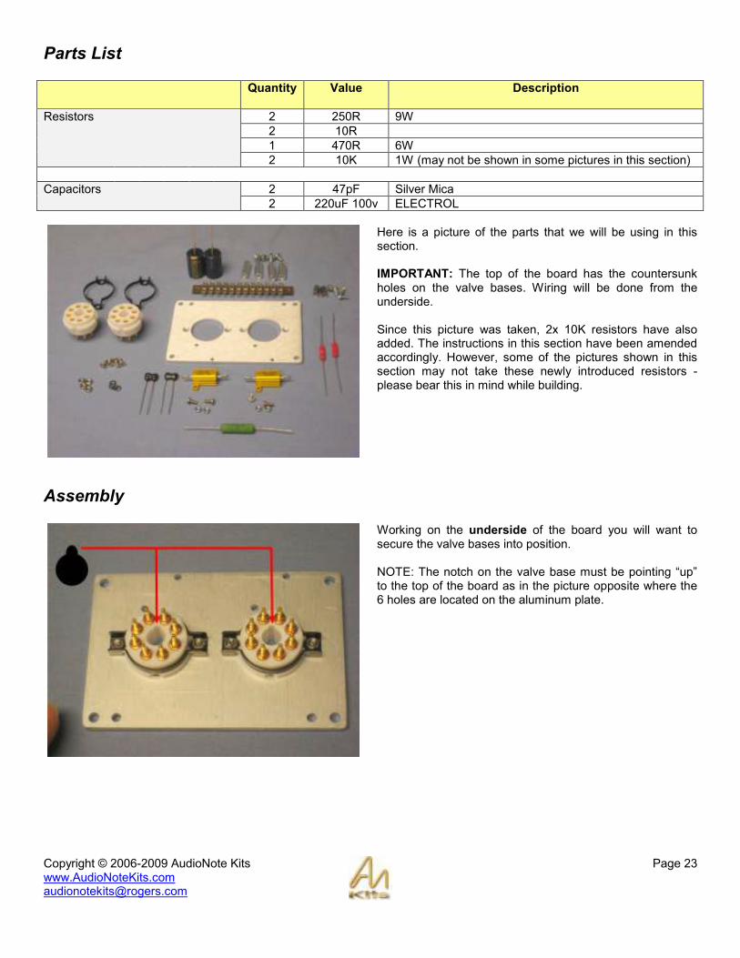
Parts List
Quantity Value Description
2 250R 9W
2 10R
1 470R 6W
Resistors
2 10K 1W (may not be shown in some pictures in this section)
2 47pF Silver Mica Capacitors
2 220uF 100v ELECTROL
Here is a picture of the parts that we will be using in this section. IMPORTANT: The top of the board has the countersunk holes on the valve bases. Wiring will be done from the underside. Since this picture was taken, 2x 10K resistors have also added. The instructions in this section have been amended accordingly. However, some of the pictures shown in this section may not take these newly introduced resistors - please bear this in mind while building.
Assembly
Working on the underside of the board you will want to secure the valve bases into position. NOTE: The notch on the valve base must be pointing “up” to the top of the board as in the picture opposite where the 6 holes are located on the aluminum plate.

Copyright © 2006-2009 AudioNote Kits www.AudioNoteKits.com [email protected]
Page 24
Position the 2x 250 ohm resistors on the board over the holes as shown. Use the supplied hardware to secure the resistors into position. Note that the nuts will be on the underside of the board.
Install the supplied 'Tag Strip' into position on the underside of the board. Use the pan screws and the hex spacers to secure the tag strip. The last step before starting the wiring is to install the spacers at the corners.
Please refer to the following diagrams that can be found in the Appendix while working in the remainder of this section:

Copyright © 2006-2009 AudioNote Kits www.AudioNoteKits.com [email protected]
Page 25
Install the two 10R resistors into position. The trick here is to route the 10 ohm red resistor through to the 250 ohm resistor as shown. Curl the leads around for good mechanical connection then solder into position and cut the remaining leg off. ALWAYS hold the excess piece so that it does not go flying off into space as this can be dangerous.
You will see that we have a GROUND that goes down the middle of the board. Take the 20 guage Black PTFE wire supplied and strip at least 1 inch of insulation. Then thread this through the two resistors as shown in these pictures. Do not solder yet...
Now before you solder we will want to add each 220uf 100v Electrolytic capacitor – this is a little tricky so take your time. Basically if you look at the schematic you will see the 2x 220uF capacitors situated on the cathode. Please read through this section before starting to install the capacitors. We are going to position the two capacitors something like the picture opposite. Remember, these are electrolytic capacitors so they must be connected with correct polarity in mind.

Copyright © 2006-2009 AudioNote Kits www.AudioNoteKits.com [email protected]
Page 26
Start by taking the Negative side of the capacitor (stripe side) and bend the leg into position and thread it through the resistor hole. Then you can solder the resistor and the capacitor leg and the stranded wire together – be careful not to burn the casing the capacitor. You can also temporarily bend the capacitor out of the way so you can make the solder connection and then bend it back.
Once that is successfully connected, you can bend the positive leg over to Pin 1 of the valve base. Note that this leg needs to touch both pins 1 and 8 so you can bend the leg to touch both pins of the valve base and then solder them both - refer to the graphic to show this connection.
Then do the same thing with the other capacitor – its definitely tricky but take your time. Make sure the Negative side of the capacitor will connect to the resistor lead and the positive side to the valve base pins 1 & 8.

Copyright © 2006-2009 AudioNote Kits www.AudioNoteKits.com [email protected]
Page 27
Now you can install the 47pf capacitor into position – refer to the graphic. On the graphic we have 12 positions on the tag strip – make sure to align the correct position with your connections (in this case the 47pf cap connects to position 11). Wrap the leg around the valve base post and solder and then cut off excess lead.
Now install the second 47pf capacitor as shown opposite (also refer to the wiring diagram).
Now add the ground LEAD. You will notice on the graphic that we have 3 grounds in the middle of the tag strip – positions 6 7 & 8 – let’s add a piece of wire to connect all three as shown here.
NOTE: These pictures are incorrect. Recently we have replaced these wires with 10K resistors that have been relocated from the driver board* So, connect a 10K resistor between -OUT (position 9 on tag strip) and pin 5 on the left-hand valve base. Connect the other between +OUT (position 5) and pin 5 on the right-hand valve base.
* Please note that other pictures in this section are incorrect also as they omit the 2x 10K resistors introduced in this last step.

Copyright © 2006-2009 AudioNote Kits www.AudioNoteKits.com [email protected]
Page 28
Use some red PTFE wire to connect pin 4 of one valve base to pin 4 of the other base.
Connect the 470R 6W resistor into position (tag strip 4 position) with pin 4 of the left valve base. That completes the component connection – now we will finish up with the filament wiring.
We are now going to add the Filament wire – the power supply will supply 6.3V AC voltage to this board via the tag strip and this will connect to pins 2 & 7 of each EL34 – Lets start this wiring by “paralleling” the pins 2 & 7 of the two valve bases. Start by cutting a short piece of the green 16Guage wire and connecting between pin 7 and pin 7 of each valve base.
Do the same for pin 2 of each valve base. It is preferable if you twist the wire. Then add the green filament wire to the positions 2 & 3 on the tag strip – cut off some strips of wire and solder into position.

Copyright © 2006-2009 AudioNote Kits www.AudioNoteKits.com [email protected]
Page 29
Then you can twist these wires slightly and connect to pins 2 & 7 of the right EL34 valve base. Congratulations! Well done if you have made it this far. You will have to repeat this whole board build for the other channel but I think a good nights sleep is in order!
Copyright © 2006-2009 AudioNote Kits www.AudioNoteKits.com [email protected]
Page 30
Section 7: Layout Recap
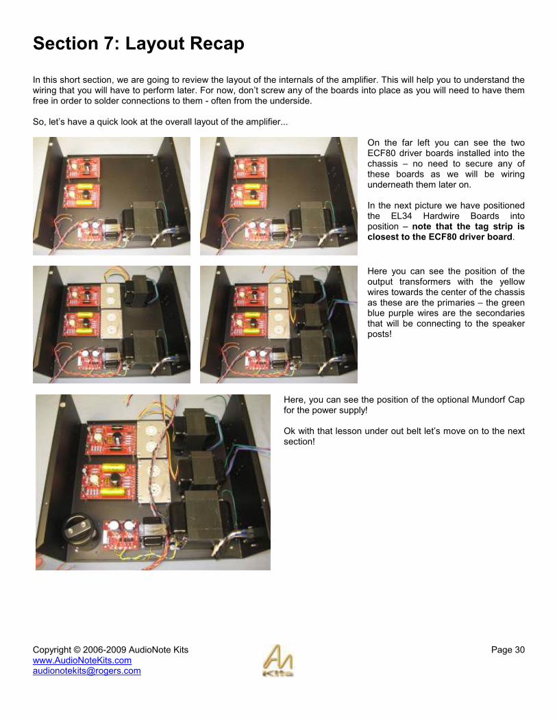
In this short section, we are going to review the layout of the internals of the amplifier. This will help you to understand the wiring that you will have to perform later. For now, don’t screw any of the boards into place as you will need to have them free in order to solder connections to them - often from the underside. So, let’s have a quick look at the overall layout of the amplifier...
On the far left you can see the two ECF80 driver boards installed into the chassis – no need to secure any of these boards as we will be wiring underneath them later on. In the next picture we have positioned the EL34 Hardwire Boards into position – note that the tag strip is closest to the ECF80 driver board.
Here you can see the position of the output transformers with the yellow wires towards the center of the chassis as these are the primaries – the green blue purple wires are the secondaries that will be connecting to the speaker posts!
Here, you can see the position of the optional Mundorf Cap for the power supply! Ok with that lesson under out belt let’s move on to the next section!

Copyright © 2006-2009 AudioNote Kits www.AudioNoteKits.com [email protected]
Page 31
Section 8: EL34 Board Filament Hook-Up
Now that we have nicely completed out EL34 hardwired boards we have to make some wiring connection to these boards.
Lay the boards out as shown in the pictures opposite – also lay down the two 6.3V filament supply twisted pairs from the Mains transformer. We will be connecting these filament wires to the Boards. For the board closest to the power supply you will want to trim the filament wires to correct length to reach the tag strip where the two green filament wires are hooked up.
FILAMENT WIRES – A short lesson We are using AC filament heating for the EL34’s and the ECF80 tubes – Basically the Mains transformer secondaries provides 6.3V AC to the tubes in order for them to “light up” – Each channel has its own Mains secondary to supply it. So you will want to strip the red & blue/white wires and insert them into the tag strip in positions 2 & 3 lining up with the green filament wires. DO not solder into position yet – the reason is that we are going to add another twisted red black wire pair to the tag strip in order to feed the filament voltage down to the ECF80 board – read on...
Now with both sets of wires into position go ahead and solder – make sure that the stranded cable completely soaks up the solder for both wires and make a good connection with the tag strip. Once this step is completed you have successfully wired in the filament wire from the Mains transformer secondary into the EL34 hardwired board and also prepared the filament wire that will be feeding the ECF80 driver board later on.

Copyright © 2006-2009 AudioNote Kits www.AudioNoteKits.com [email protected]
Page 32
Repeat the step for the outer hardwired board- as shown opposite.
Well done on completing the FILAMENT wiring section.

Copyright © 2006-2009 AudioNote Kits www.AudioNoteKits.com [email protected]
Page 33
Section 9: EL34 Board To Output Transformer Wiring
In this section we have to hook up the red and black wires from the Output transformer primary’ into the EL34 Hardwired section. On the diagram opposite, look at the connections on pin 3 of each valve.
Start by taking the red and black wires from the output transformer and twisting them. Then cut to the required length.
Copyright © 2006-2009 AudioNote Kits www.AudioNoteKits.com [email protected]
Page 34
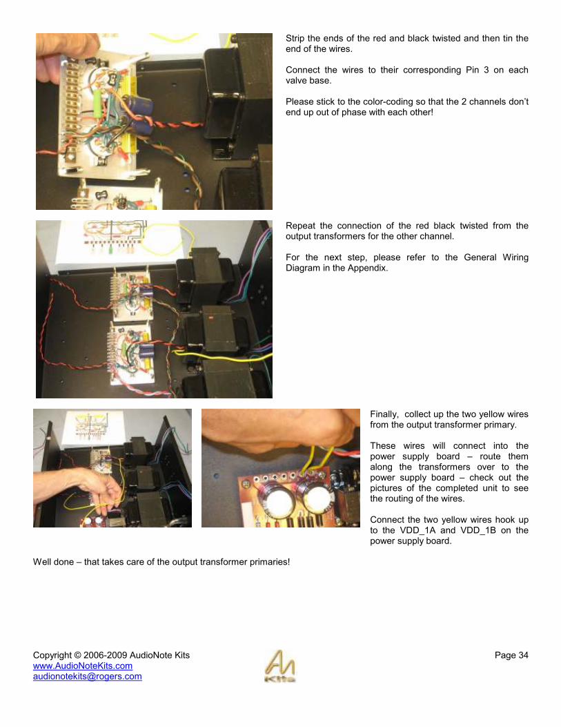
Strip the ends of the red and black twisted and then tin the end of the wires. Connect the wires to their corresponding Pin 3 on each valve base. Please stick to the color-coding so that the 2 channels don’t end up out of phase with each other!
Repeat the connection of the red black twisted from the output transformers for the other channel. For the next step, please refer to the General Wiring Diagram in the Appendix.
Finally, collect up the two yellow wires from the output transformer primary. These wires will connect into the power supply board – route them along the transformers over to the power supply board – check out the pictures of the completed unit to see the routing of the wires. Connect the two yellow wires hook up to the VDD_1A and VDD_1B on the power supply board.
Well done – that takes care of the output transformer primaries!

Copyright © 2006-2009 AudioNote Kits www.AudioNoteKits.com [email protected]
Page 35
Section 10: HT and GND Connections to EL34 Board
Before continuing, it would be a good idea to pull out the General Wiring Diagram from the Appndix. Take two lengths of RED 18 gauge 600v wire and strip the ends. Solder these to the Power Supply Board on pads VDD_2A & VDD_2B.
There is one red wire for each channel – Now connect the RED wire into the tag strip position 4. As you can see in the picture, I have wired into the same side as the resistor (470R) this is because we are later going to use the other hole on position 4 tag strip to connect to the ECF80 board.
Repeat with the other channel and the other red wire – leave a little slack in the wires as we will be eventually turning over the boards.

Copyright © 2006-2009 AudioNote Kits www.AudioNoteKits.com [email protected]
Page 36
Now do the same thing but with 2 black wires – these will be the High Voltage Grounds. Wire these into PGND_A & PGND_B. That completes the high voltage wiring!
Copyright © 2006-2009 AudioNote Kits www.AudioNoteKits.com [email protected]
Page 37
Section 11: Speaker Post Connections
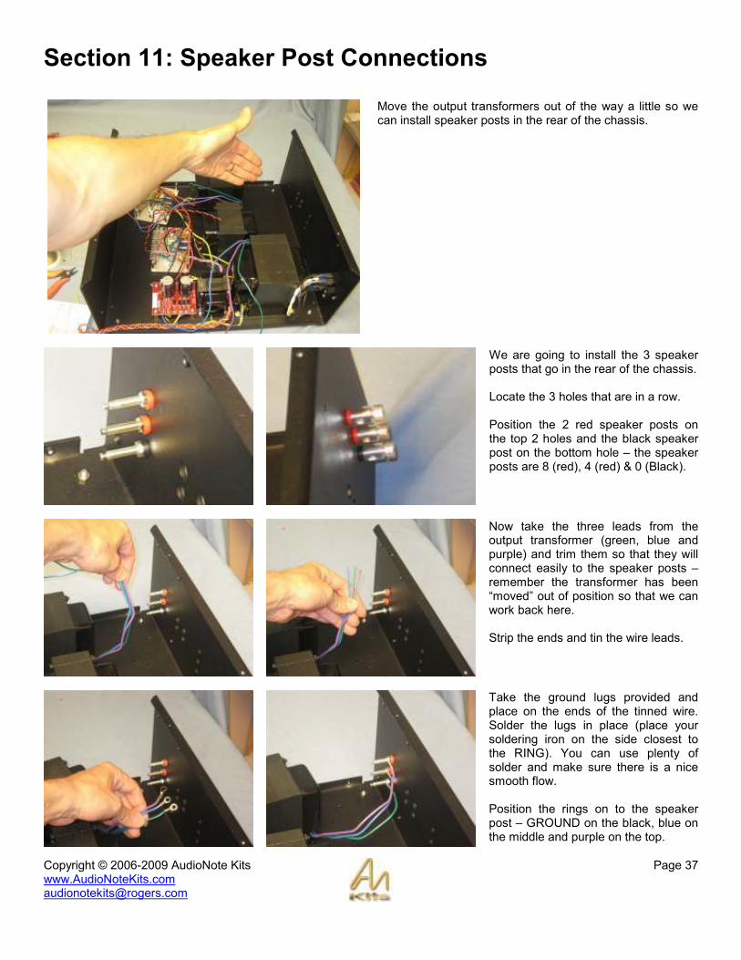
Move the output transformers out of the way a little so we can install speaker posts in the rear of the chassis.
We are going to install the 3 speaker posts that go in the rear of the chassis. Locate the 3 holes that are in a row. Position the 2 red speaker posts on the top 2 holes and the black speaker post on the bottom hole – the speaker posts are 8 (red), 4 (red) & 0 (Black).
Now take the three leads from the output transformer (green, blue and purple) and trim them so that they will connect easily to the speaker posts – remember the transformer has been “moved” out of position so that we can work back here. Strip the ends and tin the wire leads.
Take the ground lugs provided and place on the ends of the tinned wire. Solder the lugs in place (place your soldering iron on the side closest to the RING). You can use plenty of solder and make sure there is a nice smooth flow. Position the rings on to the speaker post – GROUND on the black, blue on the middle and purple on the top.
Copyright © 2006-2009 AudioNote Kits www.AudioNoteKits.com [email protected]
Page 38
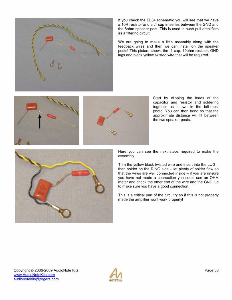
If you check the EL34 schematic you will see that we have a 10R resistor and a .1 cap in series between the GND and the 8ohm speaker post. This is used in push pull amplifiers as a filtering circuit. We are going to make a little assembly along with the feedback wires and then we can install on the speaker posts! This picture shows the .1 cap, 10ohm resistor, GND lugs and black yellow twisted wire that will be required.
Start by clipping the leads of the capacitor and resistor and soldering together as shown in the left-most photo. You can then bend so that the approximate distance will fit between the two speaker posts.
Here you can see the next steps required to make the assembly. Trim the yellow black twisted wire and insert into the LUG – then solder on the RING side – let plenty of solder flow so that the wires are well connected inside – if you are unsure you have not made a connection you could use an OHM meter and check the other end of the wire and the GND lug to make sure you have a good connection. This is a critical part of the circuitry so if this is not properly made the amplifier wont work properly!

Copyright © 2006-2009 AudioNote Kits www.AudioNoteKits.com [email protected]
Page 39
Here we are placing the assembly onto the speaker posts – be sure to position the resistor and the yellow wire side on the 8 ohm post and the cap and black wire on the ground post.
You can now use a nut to finalize each speaker post connection. Well done – now lets complete the wiring of the twisted yellow and black on the other end...
Take the yellow black wire and trim the ends. Position your EL34 board as shown and route the wire under the board.
Copyright © 2006-2009 AudioNote Kits www.AudioNoteKits.com [email protected]
Page 40
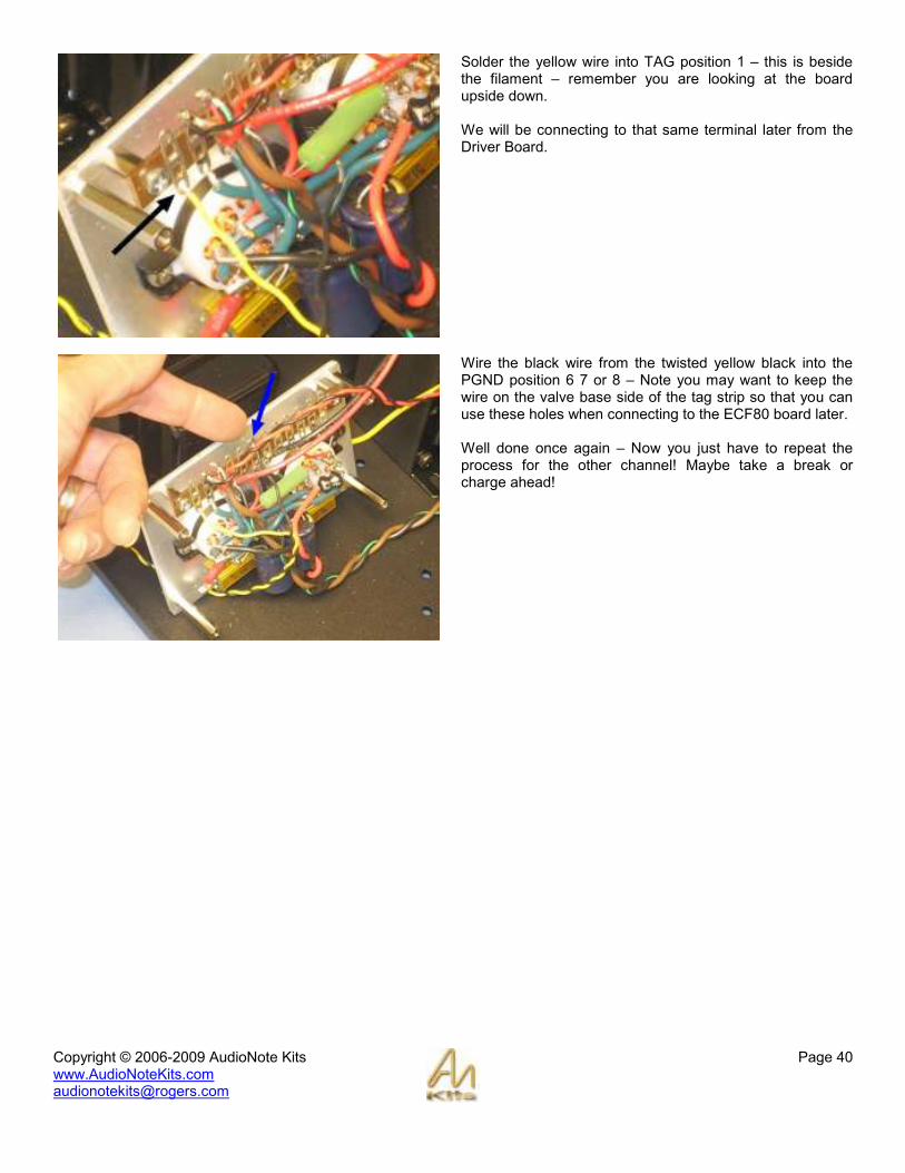
Solder the yellow wire into TAG position 1 – this is beside the filament – remember you are looking at the board upside down. We will be connecting to that same terminal later from the Driver Board.
Wire the black wire from the twisted yellow black into the PGND position 6 7 or 8 – Note you may want to keep the wire on the valve base side of the tag strip so that you can use these holes when connecting to the ECF80 board later. Well done once again – Now you just have to repeat the process for the other channel! Maybe take a break or charge ahead!

Copyright © 2006-2009 AudioNote Kits www.AudioNoteKits.com [email protected]
Page 41
Section 12: Driver Board Filament Hook-up
EXPLANATION: The filament wiring is basically AC right off the Mains secondary – these filament wires go to the EL34 hardwired board and then connect down to the ECF80 board for each channel. In order to have a very quiet amplifier, however, we need to have the AC voltage 6.3V raised up about 30V DC – We do this by connecting a single wire from the Power supply board FIL_DC over to the FIL FIL section on the ECF80 driver board.
Connect the end of the Orange wire to the FIL_DC pad in the Power Supply board.
So what you need to do is bring the twisted filament wires from the Hardwired board over to the ECF80 board along with the Orange wire from the power supply board FIL_DC. But read on to see what else you have to do with this step as you need to add one more wire...

Copyright © 2006-2009 AudioNote Kits www.AudioNoteKits.com [email protected]
Page 42
Where the orange wire (from FIL_DC) connects to the ECF80 board you need to add another orange wire to connect over to the FIL on the other ECF80 board.
To summarize: The orange wire from FIL_DC connects over to the first ECF80 board and then continues on through a second orange wire over to the second ECF80 board – meanwhile the red/black twisted wires from the hardwire boards are soldered into the FIL FIL holes on each ECF80 driver board.

Copyright © 2006-2009 AudioNote Kits www.AudioNoteKits.com [email protected]
Page 43
Section 13: ECF80 to EL34 Board Interconnections
We are now going to make the connections between the hardwire board and the ECF80 driver board. Here is a graphic showing the tag positions on the hardwire board looking from the topside now along with the connections that you are going to be making in this section.
Cut 7 short pieces of the solid core gauge wire about 1 inch long and strip off a ¼” of insulation on both ends.
Copyright © 2006-2009 AudioNote Kits www.AudioNoteKits.com [email protected]
Page 44
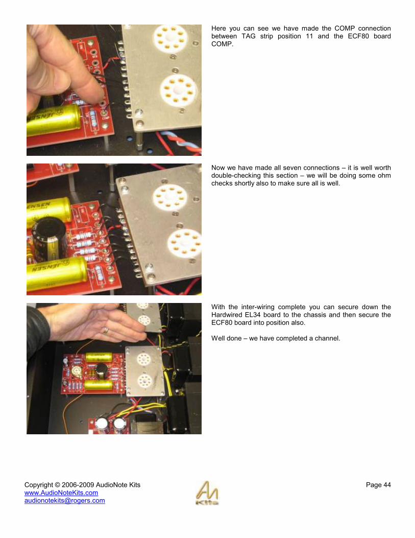
Here you can see we have made the COMP connection between TAG strip position 11 and the ECF80 board COMP.
Now we have made all seven connections – it is well worth double-checking this section – we will be doing some ohm checks shortly also to make sure all is well.
With the inter-wiring complete you can secure down the Hardwired EL34 board to the chassis and then secure the ECF80 board into position also. Well done – we have completed a channel.

Copyright © 2006-2009 AudioNote Kits www.AudioNoteKits.com [email protected]
Page 45
Let’s have a short lesson on using an OHM meter which is a most valuable tool for checking and debugging with no power on! When the probes are not touching we have an “open” circuit or in other words there is no connection between the two points we are testing – on my meter you can see it says OL for Overload or a resistance of many Mega ohms which is the same as “not connected”.
Now I am touching the probes together and the meter is showing a very low resistance of 4.7 ohms – this tells you that there is a connection –it might read 0 ohms or .5 ohms or 1 ohm also. Now lets go make our first real ohm check...
I am checking between pin 5 of the EL34 valve base, which is connected to -OUT and the ECF80 -OUT connection – reading 4 ohms. So, a good exercise would be to use your schematic and see if you can make some connections to check that everything is wired correctly. Repeat the inter-wiring and testing on the second channel of the amplifier.
You can do a little wire cleanup at this point with the tie wraps provided and your amplifier should look something like this. NOTE that we are using some different components on the left and right channel in this prototype that we are building for the manual – mainly the .22 caps – these caps can be a fun source for making changes down the road for different levels of upgrades.

Copyright © 2006-2009 AudioNote Kits www.AudioNoteKits.com [email protected]
Page 46
Section 14: RCA Connections and Final Earth
One of our last steps now is to install the input AN-A cable – this is the shielded cable that will take the input audio signal into the ECF80 driver boards.
The first step is to install the two RCA posts in the back of the unit - making sure that they do not short to the chassis. Once tightened, bend the earth lugs up slightly as show in the central picture.
Here you can see the prepared AN-A cable. One end has a red and a white lead. These will connect to the RCA’s - the red is the audio signal and the white is the ground. The other end has a red lead and a GROUND – these will connect to the ECF80 board.
The first step is to connect the end with the Red and White leads to the RCA sockets. The White lead connects to the RCA GND lug and the Red lead connects to the central signal lug.
Copyright © 2006-2009 AudioNote Kits www.AudioNoteKits.com [email protected]
Page 47
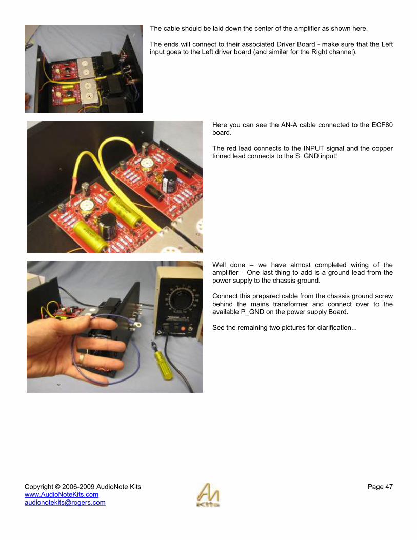
The cable should be laid down the center of the amplifier as shown here. The ends will connect to their associated Driver Board - make sure that the Left input goes to the Left driver board (and similar for the Right channel).
Here you can see the AN-A cable connected to the ECF80 board. The red lead connects to the INPUT signal and the copper tinned lead connects to the S. GND input!
Well done – we have almost completed wiring of the amplifier – One last thing to add is a ground lead from the power supply to the chassis ground. Connect this prepared cable from the chassis ground screw behind the mains transformer and connect over to the available P_GND on the power supply Board. See the remaining two pictures for clarification...

Copyright © 2006-2009 AudioNote Kits www.AudioNoteKits.com [email protected]
Page 48
Now it’s safe to say that you have completed all the wiring for the L4 Amplifier - Congratulations!

Copyright © 2006-2009 AudioNote Kits www.AudioNoteKits.com [email protected]
Page 49
Section 15: Powering On and Testing
Installing the FUSE – Pull out the fuse drawer and flip it over – then push in the fuse into position and insert back in the IEC receptacle.
The switch position above shows the unit OFF – when the 1 is pressed flush with the chassis the unit will turn ON.
Power On Procedure
If you have a Variac we will take advantage of it – it is a very useful device for slowly turning on the power to your amplifier. If you do not have a Variac then you will have to be a little more cautious and be in a position where you can switch off at the slightest hint of anything not seeming correct.

Copyright © 2006-2009 AudioNote Kits www.AudioNoteKits.com [email protected]
Page 50
Appendix
The appendix contains auxiliary information. That is information that is either common to most project manuals or any last minute pieces of information that did not make it into the manual in time. It may also contain pull-out circuit diagrams that may be handy to have outside the manual etc.
Copyright © 2006-2009 AudioNote Kits www.AudioNoteKits.com [email protected]
Page 51
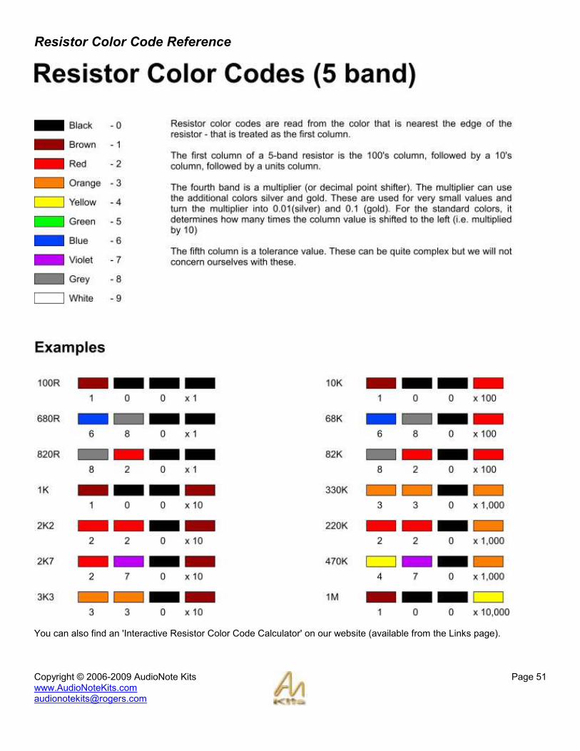
Resistor Color Code Reference
You can also find an 'Interactive Resistor Color Code Calculator' on our website (available from the Links page).

Copyright © 2006-2009 AudioNote Kits www.AudioNoteKits.com [email protected]
Page 52
Mains Transformer Windings Diagram

Copyright © 2006-2009 AudioNote Kits www.AudioNoteKits.com [email protected]
Page 53
Power Supply Board Schematic
Copyright © 2006-2009 AudioNote Kits www.AudioNoteKits.com [email protected]
Page 54
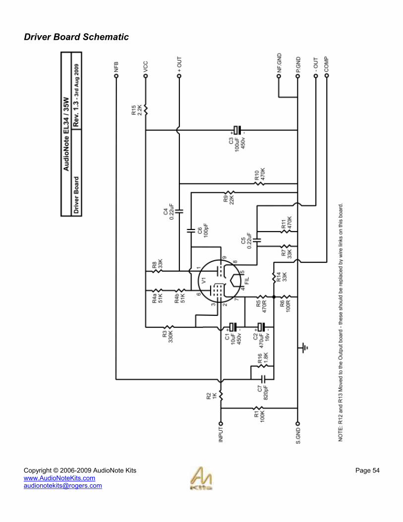
Driver Board Schematic

Copyright © 2006-2009 AudioNote Kits www.AudioNoteKits.com [email protected]
Page 55
Output Board Schematic

Copyright © 2006-2009 AudioNote Kits www.AudioNoteKits.com [email protected]
Page 56
Output Section Hardwiring Diagram

Copyright © 2006-2009 AudioNote Kits www.AudioNoteKits.com [email protected]
Page 57
General Wiring Diagram


