78
MADE IN GERMANY Manual for Planning and Installation

MADE IN GERMANY
Manual for Planning and Installation
2
RIB-ROOF INSTALLATION FILMS
FILM “LIVE INSTALLATION”: 920 SQM ROOF AREA WITHIN 2 HOURSThis documentation film shows how quickly roofing with RIB-ROOF metal roofing systems works. Direct link for smartphones, which are QR-capable, or on the Internethttp://movie-speed500.zambelli.de
FILM OF INSTALLATION PRINCIPLE RIB-ROOFSLIDING STANDING SEAM ROOFING WITH DIRECTIONAL CLIPSDiscover how the directional clip sets the direction for a linear expansion. Direct link for smartphones, which are QR-capable, or on the Internethttp://sliding-standing-seam-roofing.zambelli.de
FILM OF INSTALLATION PRINCIPLE RIB-ROOF SPEED 500CURVED PROFILED SHEETS Discover within two minutes how to install RIB-ROOF Speed 500 with curved profiled sheets and turned clips. Direct link for smartphones, which are QR-capable, or on the Internethttp://install-speed500-curved.zambelli.de
FILM OF INSTALLATION PRINCIPLE RIB-ROOF SPEED 500FLAT CLIP BORDER ON RIGID INSULATION BOARDSDiscover within two minutes how to install RIB-ROOF Speed 500 with flat clip border and directional profiles. Direct link for smartphones, which are QR-capable, or on the Internethttp://install-speed500-clipborder.zambelli.de
FILM OF MOBILE ROLLFORMINGDiscover how smoothly the production of profiled sheets with lengths over 33 m works on site by means of our mobile rollforming machines. Direct link for smartphones, which are QR-capable, or on the Internethttp://mobile-rollforming.zambelli.de
FILM OF INSTALLATION PRINCIPLE RIB-ROOF SPEED 500 Discover within two minutes how to install RIB-ROOF Speed 500 with straight profiled sheets and standard clips. Direct link for smartphones, which are QR-capable, or on the Internethttp://install-speed500.zambelli.de
FILM OF INSTALLATION PRINCIPLE RIB-ROOF 465Discover within two minutes how to install RIB-ROOF 465 with straight profiled sheets and standard clips. Direct link for smartphones, which are QR-capable, or on the Internethttp://install-465.zambelli.de
We at RIB-ROOF know that speed is only a question of technique. If it must be done quickly, you can watch our basic installation steps for our metal roofing systems RIB-ROOF Speed 500 and RIB-ROOF 465 as a film. Both on the PC and on your smartphone when travelling or on the construction site.
Zambelli channel on Youtube:You can find installation instructions, CAD visualization and construction site documentation at http://www.youtube.com/ZambelliGermany

3
CONTENT
1 GENERAL ............................................................................................................................................................................................4 1.1 Quality assurance and authorisations ................................................................................................................................................... 4 1.2 Service.................................................................................................................................................................................................... 5 1.3 Materials, surfaces and colours............................................................................................................................................................. 6 1.4 Structural physics / load bearing structures .......................................................................................................................................... 9 1.5 Transport of material / storage ............................................................................................................................................................ 11 1.6 Material processing ............................................................................................................................................................................. 14
2 RIB-ROOF METAL ROOFING SYSTEMS .................................................................................................................................16 2.1 The RIB-ROOF Principle ........................................................................................................................................................................ 16 2.2 Benefit from a system ......................................................................................................................................................................... 17 2.3 Roof built-ups....................................................................................................................................................................................... 18 2.4 Minimum roof pitch ............................................................................................................................................................................. 22 2.5 Pro/contra diffusion-open protective profiled sheet or rigid insulation boards ................................................................................ 22 2.6 Recommendation: soundproofing ....................................................................................................................................................... 23 2.7 Delivery program ................................................................................................................................................................................. 24 2.8 Tapered, curved and tapered curved profiled sheets ........................................................................................................................ 26 2.9 Span lengths / clip distances for enclosed buildings RIB-ROOF Speed 500 ....................................................................................... 28 2.10 Span lengths / clip distances for enclosed buildings RIB-ROOF 465 .................................................................................................. 34
3 INSTALLATION TECHNIQUE ......................................................................................................................................................38 3.1 RIB-ROOF Speed 500 ........................................................................................................................................................................... 38 3.2 RIB-ROOF 465 ....................................................................................................................................................................................... 44 3.3 Ridge .................................................................................................................................................................................................... 46 3.4 Transversal joint ................................................................................................................................................................................... 47 3.5 Longitudinal joint seal ......................................................................................................................................................................... 47 3.6 Important basic rules .......................................................................................................................................................................... 47 3.7 Inspection and maintenance ............................................................................................................................................................... 47
4 CONSTRUCTION DETAILS ..........................................................................................................................................................48 4.1 Ridge .................................................................................................................................................................................................... 50 4.2 Arris ...................................................................................................................................................................................................... 53 4.3 Eaves .................................................................................................................................................................................................... 54 4.4 Sloped steps ........................................................................................................................................................................................ 56 4.5 Verge .................................................................................................................................................................................................... 56 4.6 Wall connection at side / at ridge........................................................................................................................................................ 58 4.7 Internal gutter ...................................................................................................................................................................................... 60 4.8 Valleys .................................................................................................................................................................................................. 62 4.9 Roof penetrations ................................................................................................................................................................................ 63 4.10 Photovoltaic systems on RIB-ROOF ..................................................................................................................................................... 69 4.11 Snow guard and ice stopping systems, solar brackets and fall arrest system ................................................................................. 72 4.12 Flashings .............................................................................................................................................................................................. 75
4
GENERALQUALITY ASSURANCE AND AUTHORISATIONS
THEORY AND PRACTICE
QUALITY ASSURANCE AND AUTHORITIES1.1
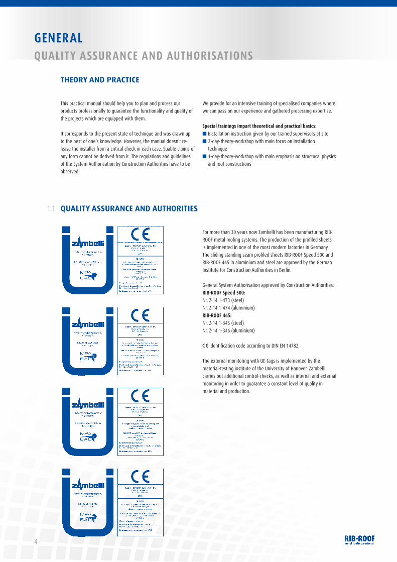
For more than 30 years now Zambelli has been manufacturing RIB-ROOF metal roofing systems. The production of the profiled sheets is implemented in one of the most modern factories in Germany. The sliding standing seam profiled sheets RIB-ROOF Speed 500 and RIB-ROOF 465 in aluminium and steel are approved by the German Institute for Construction Authorities in Berlin.
General System Authorisation approved by Construction Authorities:RIB-ROOF Speed 500:Nr. Z-14.1-473 (steel) Nr. Z-14.1-474 (aluminium)RIB-ROOF 465:Nr. Z-14.1-345 (steel) Nr. Z-14.1-346 (aluminium)
identification code according to DIN EN 14782.
The external monitoring with UE-tags is implemented by the material-testing institute of the University of Hanover. Zambelli carries out additional control-checks, as well as internal and external monitoring in order to guarantee a constant level of quality in material and production.
This practical manual should help you to plan and process our products professionally to guarantee the functionality and quality of the projects which are equipped with them.
It corresponds to the present state of technique and was drawn up to the best of one‘s knowledge. However, the manual doesn’t re-lease the installer from a critical check in each case. Suable claims of any form cannot be derived from it. The regulations and guidelines of the System Authorisation by Construction Authorities have to be observed.
We provide for an intensive training of specialised companies where we can pass on our experience and gathered processing expertise.
Special trainings impart theoretical and practical basics:■ Installation instruction given by our trained supervisors at site■ 2-day-theory-workshop with main focus on installation
technique■ 1-day-theory-workshop with main emphasis on structucal physics
and roof constructions
5
GENERAL SERvICE
Project planningOnly who plans practicable will achieve a perfect result. The RIB-ROOF team already supports you in the preparatory phase with the following services:
■ Preparation of detailed solutions■ Support with CAD detailed planning■ Preparation of individual specifications and schedules of prices■ Development of special solutions, specifications and construction
of roof mock-ups■ Statics and structural advice■ Preparation of cost estimates and calculation support■ Proposals for solution for an optimal
construction-progress planning
Construction coordination, property supervision and installation supportComplex projects and international building projects, as well as their execution, always represent a great challenge. Our roof experts support contractors, planners and laying personnel, as required, with the following services:
Project planning and construction coordination■ Drawing up of laying plans and detailed plans, as well as the
development of special solutions■ Project detailed planning■ Requirement and time planning, as well as drawing up
of bills of material■ Project management (personnel, cost and schedule control)
Installation support■ Carrying out of installation trainings■ Supervision and accompanying construction support and quality
assurance at site■ Providing of installation specialists■ Logistics support (e.g. setting up just-in-time delivery plans)■ Providing special spreader beams for lifting of profiled sheets up
to 72 m sheet length■ Carrying out of aluminium welding works on roof penetrations■ Providing of trained specialist personnel for asbestos disposal
TRG 42■ Installation of fall arrest systems
Staff installation supportWith tight deadlines, you will need all hands on deck! In particular with large-scale projects in Germany and in foreign countries, roof-laying companies come back to RIB-ROOF personnel for installation support. Here you can benefit in two ways:■ Knowledge transfer through experienced and skilled construction
workers■ On-time project realisation without any calculation surprises
SERVICE1.2
This manual guide provides you with standardised solutions. If more technical advice is needed please contact us by phone +49 (9931) 89590-0 or, of course, in a personal dialogue.
Please send your fax-request to +49 (99 31) 89 59 0 - 49or your e-mail to [email protected].
Our ordinary membership of the IFBS (“Industrieverband für Bausysteme im Metallleichtbau” – Max-Planck-Straße 4, D-40237 Düsseldorf, www.ifbs.de) helps us to achieve our stated quality aims in our quality management system. The IFBS is an important indus-trial association that represents companies operating in the field of construction systems in light metal.
RIB-ROOF metal roofing systems are characterized by an optimal fitting accuracy and the highest processing quality. The advantages of a high-quality product, its superior technical construction and comprehensive know-how during processing, form the basis for a perfect roof.
Member of:
PREIS T R ÄGER 2011Best 50
Bayerns Best 50
Bayerns
GENE
RAL
6
GENERALMATERIALS, SURFACES AND COLOURS
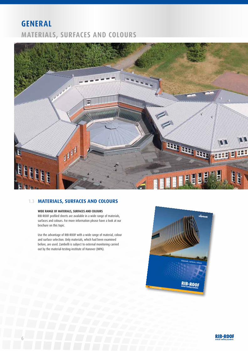
WIDE RANGE OF MATERIALS, SURFACES AND COLOURSRIB-ROOF profiled sheets are available in a wide range of materials, surfaces and colours. For more information please have a look at our brochure on this topic.
Use the advantage of RIB-ROOF with a wide range of material, colour and surface selection. Only materials, which had been examined before, are used. Zambelli is subject to external monitoring carried out by the material-testing-institute of Hanover (MPA).
MATERIALS, SURFACES AND COLOURS1.3
7
GENERAL MATERIALS, SURFACES AND COLOURS
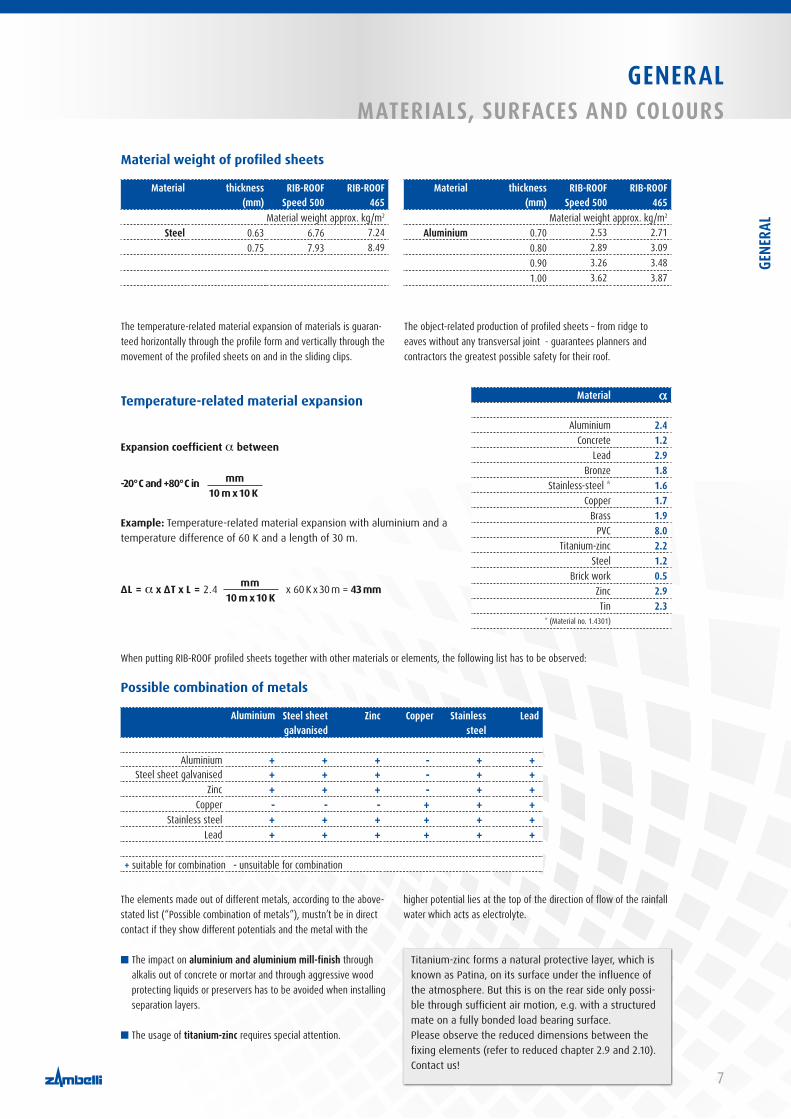
Material a
Aluminium 2.4Concrete 1.2
Lead 2.9Bronze 1.8
Stainless-steel * 1.6Copper 1.7
Brass 1.9PVC 8.0
Titanium-zinc 2.2Steel 1.2
Brick work 0.5Zinc 2.9Tin 2.3
* (Material no. 1.4301)
Temperature-related material expansion
Expansion coefficient a between
-20° C and +80° C in mm 10 m x 10 K
Example: Temperature-related material expansion with aluminium and a temperature difference of 60 K and a length of 30 m.
∆L = a x ∆T x L = 2.4 mm x 60 K x 30 m = 43 mm 10 m x 10 K
The temperature-related material expansion of materials is guaran-teed horizontally through the profile form and vertically through the movement of the profiled sheets on and in the sliding clips.
The object-related production of profiled sheets – from ridge to eaves without any transversal joint - guarantees planners and contractors the greatest possible safety for their roof.
When putting RIB-ROOF profiled sheets together with other materials or elements, the following list has to be observed:
■ The impact on aluminium and aluminium mill-finish through alkalis out of concrete or mortar and through aggressive wood protecting liquids or preservers has to be avoided when installing separation layers.
■ The usage of titanium-zinc requires special attention.
Possible combination of metals
Aluminium Steel sheet galvanised
Zinc Copper Stainless steel
Lead
Aluminium + + + - + +Steel sheet galvanised + + + - + +
Zinc + + + - + +Copper - - - + + +
Stainless steel + + + + + +Lead + + + + + +
+ suitable for combination - unsuitable for combination
Titanium-zinc forms a natural protective layer, which is known as Patina, on its surface under the influence of the atmosphere. But this is on the rear side only possi-ble through sufficient air motion, e.g. with a structured mate on a fully bonded load bearing surface.Please observe the reduced dimensions between the fixing elements (refer to reduced chapter 2.9 and 2.10). Contact us!
The elements made out of different metals, according to the above-stated list (“Possible combination of metals”), mustn’t be in direct contact if they show different potentials and the metal with the
higher potential lies at the top of the direction of flow of the rainfall water which acts as electrolyte.
Material weight of profiled sheets
Material thickness (mm)
RIB-ROOFSpeed 500
RIB-ROOF 465
Material thickness (mm)
RIB-ROOFSpeed 500
RIB-ROOF 465
Material weight approx. kg/m2 Material weight approx. kg/m2
Steel 0.63 6.76 7.24 Aluminium 0.70 2.53 2.710.75 7.93 8.49 0.80 2.89 3.09
0.90 3.26 3.481.00 3.62 3.87
GENE
RAL

8
GENERALMATERIALS, SURFACES AND COLOURS
According to DIN 55631: 2010-04, table A.1 and A.2 the following “expected duration of pro-tection” is each assigned to RIB-ROOF system construction components:
C2 C3 C4 C5-I C5-ML M H L M H L M H L M H L M H
Alu-zincsteel sheet with alu-zinc alloy, coating thickness 25um, (System-no. A1.11)
4 4 4 4 4 4 4 4 4 4 4 4 4
Steel sheetgalvanised on both sides and coil coated, front side 25um polyester lacquer (System-no. A2.3)
4 4 4 4 4 4* 4
Steel sheetgalvanised on both sides and coil coated, front side 25um PVDF lacquer, (System-no. A2.14)
4 4 4 4 4 4 4 4 4
* For coastal areas with salt pollution not to recommend
Selection criteria for corrosion-protection-systems,Corrosion categories according to DIN EN ISO 12944 for steel sheets
The assignment of the corrosion-protection-classes according to DIN EN 18807 to corrosion categories according to DIN EN 12944-2 is stated dependent on the duration of protection and the atmospheric demands stated in table 1, DIN 55634:2010-04.
Corrosion categories/
corrosion impact according
to DIN EN ISO 12944-2
Duration of protection
Examples for environment (for your information)
Corrosionpersistence
category b
Corrosion-protection class a
outside inside accessible c inaccessible
C1 insignificant
low
–
heated buildings with neutral atmospheres, e.g. offices, stores, schools, hotels
RC1
I I
medium I I
high I I
C2 low
low atmosphere with low soiling. Most of the time rural areas
unheated buildings where condensation can occur, e.g. stocks, sport halls
RC2
I I I
medium I I I
high I I I I
C3 moderate
low city and industry atmos-phere, moderate soiling through sulphur dioxide. coastal areas with low salt pollution
production halls with high humidity and a bit air pol-lution, e.g. machines for food production, laundries, breweries, dairies
RC3
I I I I I
medium I I I I I
high I I I I I
C4 strong
low industrial areas and coas-tal regions with moderate salt pollution
chemical industries, swim-ming pools, boat sheds built above sea water
RC4
I I I I I I
medium I I I I I I
high I I I _d
C5-I very strong
(industry)
low industrial areas with high humidity and aggressive atmosphere
buildings or areas with almost permanent condensation and high pollution
RC5
I I I _d
medium I I I _d
high _d _d
C5-M very strong
(sea)
lowcoastal and off-shore are-as with high salt pollution
buildings or areas with almost permanent condensation and high pollution
I I I _d
medium I I I _d
high _d _da The stating of the corrosion-protection-class only has the function of classifying previous approved demands by Building Authorities for the new European classification system composed of the corrosion category and the duration of protection.
b According to DIN EN 10169 only for fire coatingc The practicability of control and repair measures for “accessible” classified areas already has to be planned when producing. The accessibility can be guaran-teed by e.g. straight ladders, stand framings, fixed, freely-suspended or led working levels.
d The corrosion-protection classes aren’t applicable with very high corrosion loading and high time of protection and with special loading. The required measu-res with this loadings and conditions have to be determined in each case.

9
GENERAL STRUCTURAL PHYSICS / LOAD BEARING STRUCTURES
STRUCTURAL PHYSICS / LOAD BEARING STRUCTURE
STRUCTURAL PHYSICS
1.4
1.4.1
We don’t want to deal here with the installation of the load bearing structure and substructure for RIB-ROOF profiled sheets in detail, we only want to say:The guidelines for the execution of metal roofs, claddings and plumber published by the Central Association for Sanitary, Heating and Air Conditioning as well as the relevant DIN- and EN-standards differentiate the so-called single-deck roof constructions with ther-mal insulation (known as warm roof) or without thermal insulation, respectively, from the double-deck roof construction with air cavity ventilation/ventilation (known as cold roof).
Metal roofs with air ventilation have a ventilated cavity with ventilated openings – as a rule, on eaves and ridge – in order to con-densate the cold metal rear side and to be able to expel the existing amount of humidity in the cavity.
The sufficient dimension is construction-related and has to be considered when planning and executing. A mechanical ventilation is necessary with a roof construction which doesn’t have a natural air lift. You might be aware of the fact that a large number of factors can negatively affect the functionality of the ventilation of a double-deck roof construction. For buildings which are in the planning phase, a single-deck construction with a vapour barrier membrane (Sd-value ≥ 100 m) without any ventilation is recom mended.
Roof constructions with thermal-insulation and non-ventilation require a vapour barrier membrane for bordering and above-ground building components as well as all roof penetrations so that every-thing is wind-proof and vapour-proof.When determining the U-value for the entire roof the thermal-
protection-evidence, according to EnEV, for the influence of fixing constructions has to be considered. The results of calculations made by the Research Institute for Thermal Insulation (“Forschungsinstitut für Wärmeschutz e.V.”) clearly show the negative effect of metal dis-tance structures when made without thermal separation. They act as thermal bridges and, therefore, reduce the insulation of the building. It is thus recommended that distance constructions/roof structures with good U-values according to chapter 2.3 “Roof strucuture” should be used.
The guidelines of the Central Association for Sanitary, Heating and Air Conditioning (ZVSHK) recommend the installation of a vapour-dif-fusion-opened protective sheet on thermal insulation under certain conditions in order to protect them against humidity and secondary melt water which may occur on the rear side of profiled sheets under inclement weather conditions. We refer to a precise processing of bordering and above-ground building components.
You can dispose of the vapour-diffusion-open protective sheet if the mineral thermal insulation which lays under it is compressed about approx. 20 mm.
More information you will find in chapter 2.5 “Pro/Contra diffusion-open protective sheet or rigid insulation boards”.
DIN 4102 DIN 4108 DIN 4109
An important recondition for functionality, quality and efficiency of a building is the observance of the basic rules of building physics. You can find them e.g. in the German Industry Standards:
4102 – Fire behaviour of building materials and building components,4108 – Thermal protection and energy economy in buildings and4109 – Sound insulation in buildings
They have to be observed in the individual cases.
GENE
RAL
10
GENERALSTRUCTURAL PHYSICS / LOAD BEARING STRUCTURES
LOAD BEARING STRUCTURES1.4.2
One of the most common load bearing structures are trapezoidal steel profiles. This design forms the basis for the following descrip-tions and photographs.
The installation on these and alternative substructures and possible fixing elements are summarised in the table below.
SUBSTRUCUTURES
Substructure Fixing material
Wooden lathing / purlins wood screws with full thread 6 x 40 mm
Timber boarding t = minimum 24.0 mm wood screws with full thread 6x 40 mm or 5 x 30 mm
Steel purlins t ≤ 4.0 mmself-drilling screws 5.5 x 25 mm or blind rivets out of aluminium with head Ø 15.0 mmor 4.8 x 17 mm; pre-drilling necessary
Steel purlins t ≥ 4.0 mmblind aluminium rivets with head Ø 15.0 mm or 4.8 x 17 mm; pre-drilling necessary or standard clips RIB-ROOF Speed 500 without holes with Hilti-setting bolts
Trapezoidal profiles self-drilling screws 5.5 x 25 mm
Wooden lathing on trapezoidal profilesself-drilling screws Torx T25SFS SD2 ⁄ KL-(S)-S11-6*LEjot JT3 ⁄ JT2-ST-2-6,0*L
Aerated concreteSFS-IGR, Ejot SDP(please observe extracts)
Reinforced concrete dowel system Ejot SDF 8.0 mm
Table of possible substructures and the necessary fixing element; fixing element for other substructures on request.
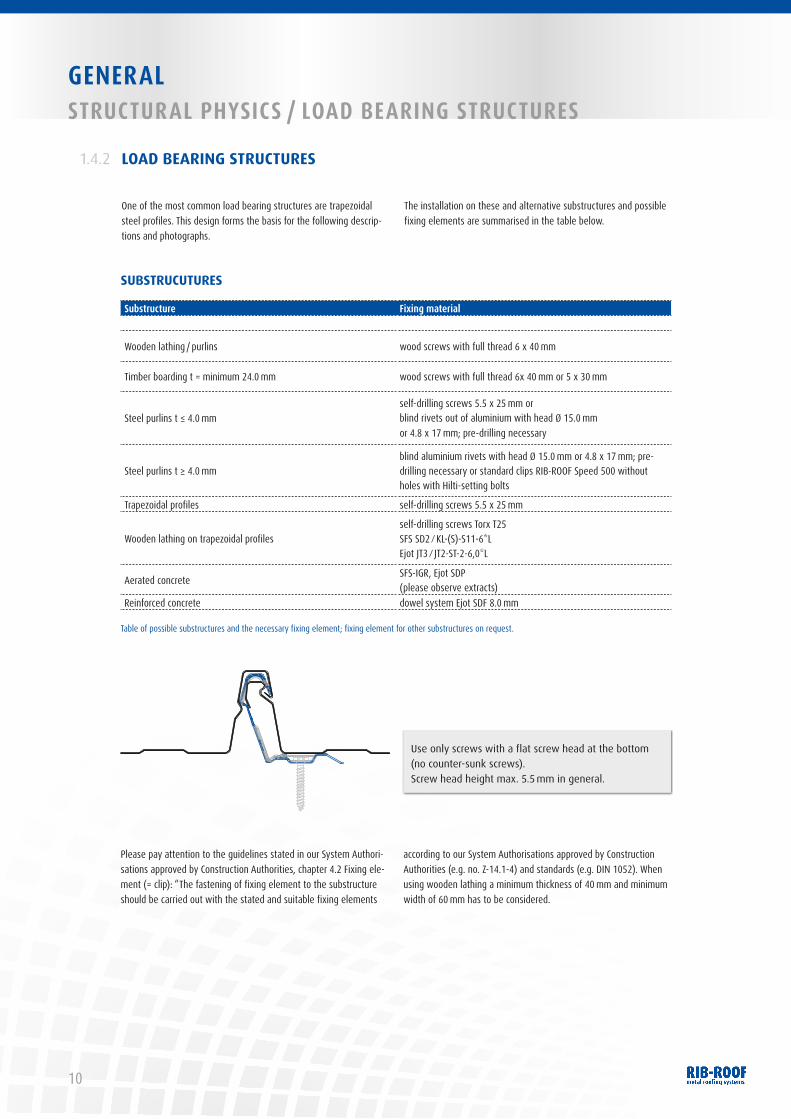
Please pay attention to the guidelines stated in our System Authori-sations approved by Construction Authorities, chapter 4.2 Fixing ele-ment (= clip): “The fastening of fixing element to the substructure should be carried out with the stated and suitable fixing elements
according to our System Authorisations approved by Construction Authorities (e.g. no. Z-14.1-4) and standards (e.g. DIN 1052). When using wooden lathing a minimum thickness of 40 mm and minimum width of 60 mm has to be considered.
Use only screws with a flat screw head at the bottom (no counter-sunk screws). Screw head height max. 5.5 mm in general.
11
GENERALTRANSPORT OF MATERIAL / STORAGE
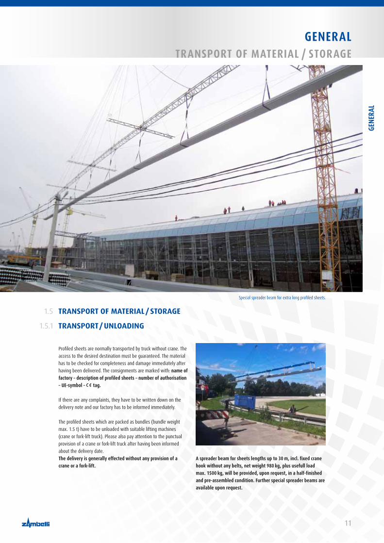
Profiled sheets are normally transported by truck without crane. The access to the desired destination must be guaranteed. The material has to be checked for completeness and damage immediately after having been delivered. The consignments are marked with: name of factory – description of profiled sheets – number of authorisation – UE-symbol – tag.
If there are any complaints, they have to be written down on the delivery note and our factory has to be informed immediately.
The profiled sheets which are packed as bundles (bundle weight max. 1.5 t) have to be unloaded with suitable lifting machines (crane or fork-lift truck). Please also pay attention to the punctual provision of a crane or fork-lift truck after having been informed about the delivery date.The delivery is generally effected without any provision of a crane or a fork-lift.
A spreader beam for sheets lengths up to 30 m, incl. fixed crane hook without any belts, net weight 980 kg, plus usefull load max. 1500 kg, will be provided, upon request, in a half-finished and pre-assembled condition. Further special spreader beams are available upon request.
TRANSPORT OF MATERIAL / STORAGE
TRANSPORT / UNLOADING
1.5
1.5.1
Special spreader beam for extra long profiled sheets.
GENE
RAL
12
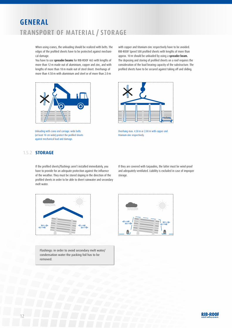
Flashings: in order to avoid secondary melt water/condensation water the packing foil has to be removed.
GENERALTRANSPORT OF MATERIAL / STORAGE
STORAGE1.5.2
If the profiled sheets/flashings aren’t installed immediately, you have to provide for an adequate protection against the influence of the weather. They must be stored sloping in the direction of the profiled sheets in order to be able to divert rainwater and secondary melt water.
If they are covered with tarpaulins, the latter must be wind-proof and adequately ventilated. Liability is excluded in case of improper storage.
When using cranes, the unloading should be realized with belts. The edges of the profiled sheets have to be protected against mechani-cal damage.You have to use spreader beams for RIB-ROOF 465 with lengths of more than 12 m made out of aluminium, copper and zinc, and with lengths of more than 18 m made out of steel sheet. Overhangs of more than 4.50 m with aluminium and steel or of more than 2.0 m
with copper and titanium-zinc respectively have to be avoided. RIB-ROOF Speed 500 profiled sheets with lengths of more than approx. 10 m should be unloaded by using a spreader beam.The deposing and storing of profiled sheets on a roof requires the consideration of the load bearing capacity of the substructure. The profiled sheets have to be secured against taking off and sliding.
Auskragung
Auskragung
Auskragung
overhang
Overhang max. 4.50 m or 2.00 m with copper and titanium-zinc respectively.
Unloading with crane end carriage: wide belts (at least 10 cm wide) protect the profiled sheets against mechanical load and damage.

13
GENERALTRANSPORT OF MATERIAL / STORAGE
PROFILING AT SITE / MOBILE ROLLFORMING1.5.3
The production of profiled sheets with lengths of more than 33 m is possible on site with our mobile rollforming machines.
Watch our film on this subject:http://mobile-rollforming.zambelli.de
GENE
RAL
14
GENERALMATERIAL PROCESSING
MATERIAL PROCESSING
DIVIDING AND CUTTING
1.6
1.6.1
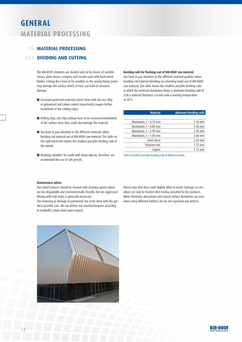
The RIB-ROOF elements are divided and cut by means of suitable shears, plate shears, compass and circular saws with hard-metal blades. Cutting discs have to be avoided, as the arising flying sparks may damage the surface which, in turn, can lead to corrosion damage.
■ Corrosion-protected materials (steel sheet with alu-zinc alloy or galvanised and colour-coated respectively) require further treatments of the cutting edges.
■ Drilling chips and chip cuttings have to be removed immediately of the surface since they could also damage the material.
■ You have to pay attention to the different materials when bending coil material out of RIB-ROOF raw material. The table on the right-hand-side shows the smallest possible bending radii of the metals.
■ Markings shouldn‘t be made with sharp objects; therefore, we recommend the use of soft pencils.
Bending radii for flashings out of RIB-ROOF raw materialYou have to pay attention to the different material qualities when bending coil material (bending on a bending bank) out of RIB-ROOF raw material. The table shows the smallest possible bending radii in which the material aluminium shows a minimum bending radii of 3.00 x material thickness t in mm with a working temperature of 20°C.
Material Minimum bending radii
Aluminium, t = 0.70 mm 2.10 mm Aluminium, t = 0.80 mm 2.40 mmAluminium, t = 0.90 mm 2.70 mmAluminium, t = 1.00 mm 3.00 mm
Steel sheet 2.50 mmTitanium-zinc 1.75 mm
Copper 1.75 mm
Table of smallest possible bending radii of different metals
Maintenance adviceThe metal surfaces should be cleaned with cleaning agents which are bio-degradable and environmentally-friendly, but not aggressive.Rinsing with cold water is generally necessary. The removing of damage to paintworks has to be done with the gre-atest possible care. We can deliver our standard lacquers according to Zambelli’s colour chart upon request.
Please note that they could slightly differ in shade. Damage on zinc-alloys can only be treated after having consulted to the producer. Minor chromatic aberrations and natural surface deviations can arise when using different batches, but do not represent any defects.
15
GENERALMATERIAL PROCESSING
FASTENING TECHNOLOGY / WELDING / SOLDERING1.6.2
You have to pay attention to the different materials when connec-ting metals (please refer to chapter 1.3).The lacquer of colour-coated aluminium has to be removed before welding and soldering. You have to lacquer the blank surface with
the appropriate lacquer after having finished working. The fastening technologies are described in detail in the instructions of the mate-rial producers of aluminium, steel sheet, titanium-zinc and copper. Upon request, we will suggest you specialised RIB-ROOF welders.
BONDING1.6.3
A possible alternative is the bonding of metals according to the explanatory leaflet “Bonding in plumbing” published by the Central Association for Sanitary, Heating and Air Condition (ZVSHK) in 53757
St. Augustin, Germany. Single-component polyurethane adhesives are normally used in plumbing.
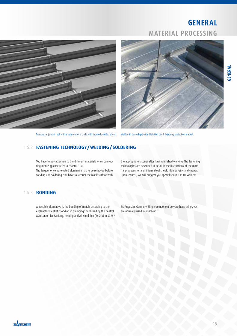
Transversal joint at roof with a segment of a circle with tapered profiled sheets Welded-in dome light with dilatation band; lightning protection bracket
GENE
RAL
RIB-ROOF METAL ROOFING SYSTEMSTHE RIB-ROOF PRINCIPLE
16
THE RIB-ROOF PRINCIPLE2.1
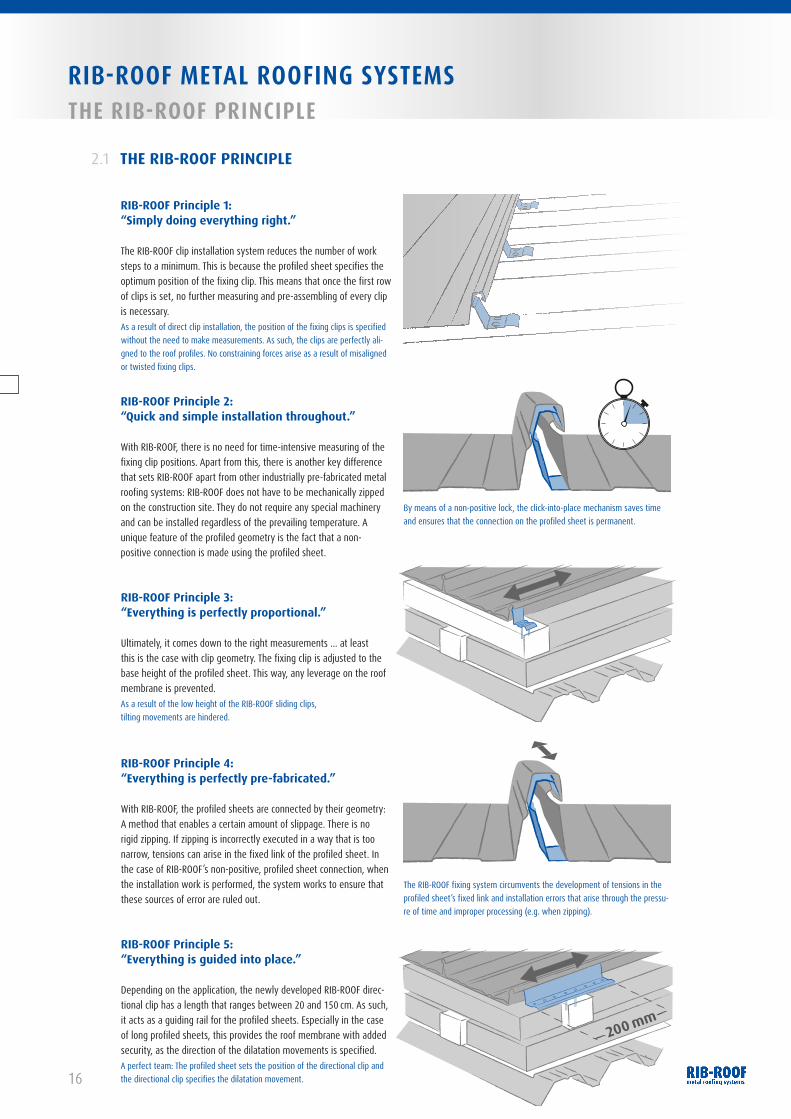
RIB-ROOF Principle 1:“Simply doing everything right.”
The RIB-ROOF clip installation system reduces the number of work steps to a minimum. This is because the profiled sheet specifies the optimum position of the fixing clip. This means that once the first row of clips is set, no further measuring and pre-assembling of every clip is necessary.
RIB-ROOF Principle 2:“Quick and simple installation throughout.”
With RIB-ROOF, there is no need for time-intensive measuring of the fixing clip positions. Apart from this, there is another key difference that sets RIB-ROOF apart from other industrially pre-fabricated metal roofing systems: RIB-ROOF does not have to be mechanically zipped on the construction site. They do not require any special machinery and can be installed regardless of the prevailing temperature. A unique feature of the profiled geometry is the fact that a non-positive connection is made using the profiled sheet.
RIB-ROOF Principle 3:“Everything is perfectly proportional.”
Ultimately, it comes down to the right measurements … at least this is the case with clip geometry. The fixing clip is adjusted to the base height of the profiled sheet. This way, any leverage on the roof membrane is prevented.
RIB-ROOF Principle 4:“Everything is perfectly pre-fabricated.”
With RIB-ROOF, the profiled sheets are connected by their geometry: A method that enables a certain amount of slippage. There is no rigid zipping. If zipping is incorrectly executed in a way that is too narrow, tensions can arise in the fixed link of the profiled sheet. In the case of RIB-ROOF’s non-positive, profiled sheet connection, when the installation work is performed, the system works to ensure that these sources of error are ruled out.
RIB-ROOF Principle 5:“Everything is guided into place.”
Depending on the application, the newly developed RIB-ROOF direc-tional clip has a length that ranges between 20 and 150 cm. As such, it acts as a guiding rail for the profiled sheets. Especially in the case of long profiled sheets, this provides the roof membrane with added security, as the direction of the dilatation movements is specified.
As a result of direct clip installation, the position of the fixing clips is specified without the need to make measurements. As such, the clips are perfectly ali-gned to the roof profiles. No constraining forces arise as a result of misaligned or twisted fixing clips.
As a result of the low height of the RIB-ROOF sliding clips, tilting movements are hindered.
The RIB-ROOF fixing system circumvents the development of tensions in the profiled sheet’s fixed link and installation errors that arise through the pressu-re of time and improper processing (e.g. when zipping).
A perfect team: The profiled sheet sets the position of the directional clip and the directional clip specifies the dilatation movement.
By means of a non-positive lock, the click-into-place mechanism saves time and ensures that the connection on the profiled sheet is permanent.
200 mm

RIB-ROOF METAL ROOFING SYSTEMSBENEFIT FROM A SYSTEM
17
BENEFIT FROM A SYSTEM2.2
RIB-ROOF Speed 500directional profile 750 mm
RIB-ROOF Speed 500 standard clip
RIB-ROOF Speed 500directional clip 200 mm
Simple installation technology Setting, swivelling, clicking. RIB-ROOF metal roofing systems provide you with a fast, simplified and, especially, uncomplicated way to car-ry out the installation. As such, the principles behind the RIB-ROOF form the basis for a roof where long-term functionality is ensured.
The innovative fixing systemsRIB-ROOF is a sliding standing seam roofing. The RIB-ROOF Principles are based on improvements to the way the roof cladding is fixed. This is because the fixing systems are developed in such a way that no tensions arise through wind load or dilatation that is a conse-quence of temperature-related conditions. Good sliding qualities ensure long-term functional security.
The crucial saving in terms of timeWith very short construction times, the optimisation of costs and deadlines plays an important role. RIB-ROOF metal roofing systems allow for intuitive laying. This way, the installation is carried out rapidly in one pass. This brings the added bonus of an unbeatable saving in terms of time. As such, in the business of constructing commercial buildings, the laying of a RIB-ROOF roof within a few hours is no longer the exception, but the rule.
An objective viewEconomic efficiency is always relative to cost and useful life. RIB-ROOF metal roofing systems stand for advanced technology which simplifies planning and installation. As a result, this approach provides a functionally durable roof. This means less costs and more benefit from a long service life. A calculation that always works in your favour.
Accessible and self-supportingTherefore, suitable for all standard fields of application on purlins or on fully-bonded surfaces from single-deck rear-ventilated cold roof to thermally-insulated non-ventilated roof structure.
Permanently rain-proofAs a result of a penetration- and transversal-seam-free installation of the profiled sheets and penetration-free installation of the acces-sories on the profiled sheet seam.
SustainabilityRIB-ROOF sliding standing seam roofs form sustainable constructions and also stand for a cost-efficient roofing systems with aesthetic de-mands. High quality, durability, easy maintenance and recycling form the basis for a sustainable roofing system. Metal as a construction material and the system advantages provide for the highest safety against forces of nature and fire. Integral considerations of the sum of investigation and maintenance costs show that this method of building isn’t only durable but also extremely economic. For more information about sustainability please refer to the IFBS-brochure “Standing seam roofing. The sustainable method of building.”
Wide range of different constructionsRIB-ROOF profiled sheets are available straight, conical, curved or conical curved. For sheet lengths of more than 33 m, the profiled sheets will be profiled and curved at site, upon request. Apart from the standard widths, we are also prepared to produce project-related measurements.
Perfect system accessoriesThe complete range of pre-assembled accessories allows for a flexible, efficient planning and for a quick, precise installation. Other accessories, such as fall arrest systems, snow guard elements, tread supports and solar brackets, are installed perforation-free on the seams of the profiled sheets.
RIB-
ROOF
MET
AL R
OOFI
NG S
YSTE
MS
18
RIB-ROOF METAL ROOFING SYSTEMSROOF BUILD-UPS
ROOF BUILD-UPS
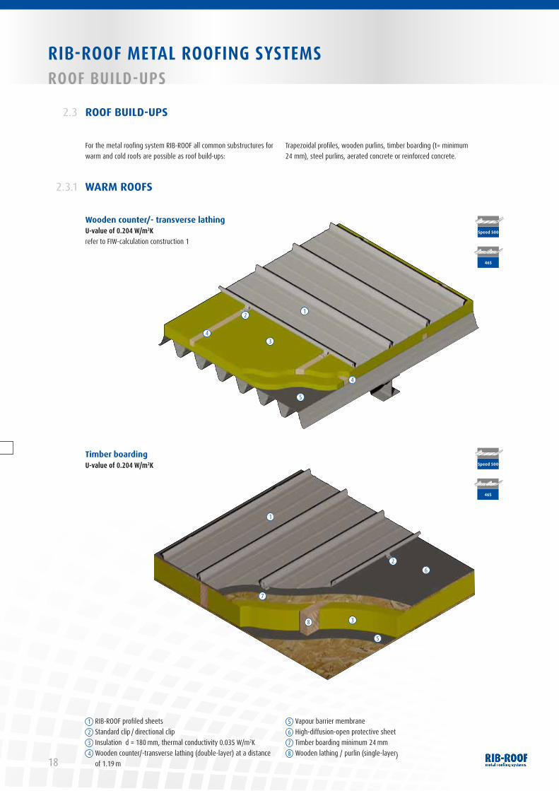
For the metal roofing system RIB-ROOF all common substructures for warm and cold roofs are possible as roof build-ups:
Trapezoidal profiles, wooden purlins, timber boarding (t= minimum 24 mm), steel purlins, aerated concrete or reinforced concrete.
2.3
WARM ROOFS 2.3.1
1 RIB-ROOF profiled sheets2 Standard clip / directional clip3 Insulation d = 180 mm, thermal conductivity 0.035 W/m2K4 Wooden counter/-transverse lathing (double-layer) at a distance
of 1.19 m
5 Vapour barrier membrane6 High-diffusion-open protective sheet7 Timber boarding minimum 24 mm 8 Wooden lathing / purlin (single-layer)
Timber boardingU-value of 0.204 W/m2K
Wooden counter/- transverse lathingU-value of 0.204 W/m2Krefer to FIW-calculation construction 1
7
6
8 3
2
1
465
465
Speed 500
Speed 500
5
5
43
2 1
4

19
RIB-ROOF METAL ROOFING SYSTEMS ROOF BUILD-UPS
Speed 500
Speed 500
On trapezoidal profiles, parallel to eaves, or alternatively ridge – eaves on trapezoidal profiles (only with top chord repetition every 125, 250 or 500 mm)
Roof build-ups with flat clip borderU-value of 0.208 W/m2Krefer to FIW-calculation construction 2a
Installation on fully-inserted supports with clip borderRIB-ROOF Speed 500 can alternatively be installed on fully-inserted supports. Another alternative besides timber boarding is the rigid insulation boards which are also resistant to pressure (application type WD).
As desired, the profiled sheets can be installed on distance profiles
which correspond to the thickness of a thermal insulation, or on clip borders – option perforated or flat – which are fastened to the roof structure.
Open butt joints have to be avoided when installing insulation panels. This design is also transferable to RIB-ROOF 465 when using the so-called pressure-distributing profiles.
On trapezoidal profiles (any geometry)Ridge – eavesor on aerated concrete
Roof build-ups with perforated clip borderU-value of 0.208 W/m2Krefer to FIW-calculation construction 2a
1 RIB-ROOF profiled sheets2 Rigid insulation boards d = 180 mm,
thermal conductivity 0.037 W/m2K3 Flat clip border at a distance of 1.8 m
4 Vapour barrier membrane5 Perforated clip border at a distance of 1.8 m
4
4
2
3
2
5
1
1
A regular offsetting of the flat clip borders can be necessary due to statical reasons
RIB-
ROOF
MET
AL R
OOFI
NG S
YSTE
MS

20
BlindtextBlindtextRIB-ROOF METAL ROOFING SYSTEMSROOF BUILD-UPS
1 RIB-ROOF profiled sheets2 Standard clip / directional clip3 Thermal insulation d = 180 mm,
thermal conductivity 0.035 W/m2K
4 Double-layer of Z-profiles with thermal separation strips on each Z-profile
5 Vapour barrier membrane6 Single-layer of Z-profile with two thermal separation strips
Single-layer of Z-profiles with two thermal separation strips■ at a distance of 1.8 m U-value of 0.271 W/m2K
refer to FIW-calculation construction 4a■ at a distance of 1.2 m U-value of 0.314 W/m2K
refer to FIW-calculation construction 4b
Double-layer of Z-profiles with one thermal separation strip on each Z-profile■ at a distance of 1.8 m U-value of 0.216 W/m2K
refer to FIW-calculation construction 3a■ at a distance of 1.2 m U-value of 0.240 W/m2K
refer to FIW-calculation construction 3b
4
5
3
2
1
4
465
465
Speed 500
Speed 500
6
3
1
2
5
21
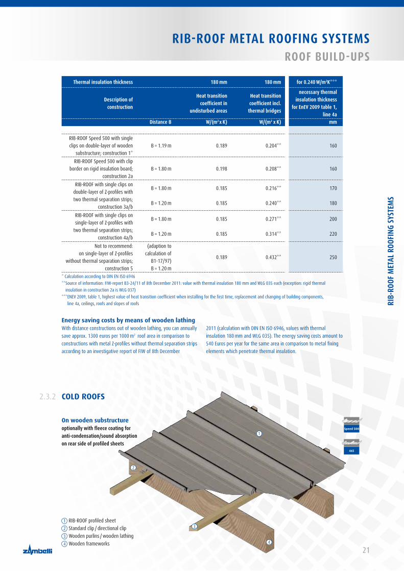
RIB-ROOF METAL ROOFING SYSTEMS ROOF BUILD-UPS
Thermal insulation thickness 180 mm 180 mm for 0.240 W/m2K***
Description of construction
Heat transition coefficient in
undisturbed areas
Heat transition coefficient incl.
thermal bridges
necessary thermal insulation thickness
for EnEv 2009 table 1, line 4a
Distance B W/(m2 x K) W/(m2 x K) mm
RIB-ROOF Speed 500 with single clips on double-layer of wooden
substructure; construction 1*B = 1.19 m 0.189 0.204** 160
RIB-ROOF Speed 500 with clip border on rigid insulation board;
construction 2aB = 1.80 m 0.198 0.208** 160
RIB-ROOF with single clips on double-layer of Z-profiles with two thermal separation strips;
construction 3a/b
B = 1.80 m
B = 1.20 m
0.185
0.185
0.216**
0.240**
170
180
RIB-ROOF with single clips on single-layer of Z-profiles with
two thermal separation strips; construction 4a/b
B = 1.80 m
B = 1.20 m
0.185
0.185
0.271**
0.314**
200
220
Not to recommend:on single-layer of Z-profiles
without thermal separation strips; construction 5
(adaption to calculation of
B1-17/97) B = 1.20 m
0.189 0.432** 250
* Calculation according to DIN EN ISO 6946** Source of information: FIW-report B3-24/11 of 8th December 2011: value with thermal insulation 180 mm and WLG 035 each (exception: rigid thermal
insulation in construction 2a is WLG 037)*** ENEV 2009, table 1, highest value of heat transition coefficient when installing for the first time, replacement and changing of building components,
line 4a, ceilings, roofs and slopes of roofs
Energy saving costs by means of wooden lathingWith distance constructions out of wooden lathing, you can annually save approx. 1300 euros per 1000 m2 roof area in comparison to constructions with metal Z-profiles without thermal separation strips according to an investigative report of FIW of 8th December
2011 (calculation with DIN EN ISO 6946, values with thermal insulation 180 mm and WLG 035). The energy saving costs amount to 540 Euros per year for the same area in comparison to metal fixing elements which penetrate thermal insulation.
465
Speed 500
COLD ROOFS 2.3.2
On wooden substructureoptionally with fleece coating for anti-condensation/sound absorption on rear side of profiled sheets
1 RIB-ROOF profiled sheet2 Standard clip / directional clip3 Wooden purlins / wooden lathing4 Wooden frameworks
1
2
3
4
RIB-
ROOF
MET
AL R
OOFI
NG S
YSTE
MS

22
RIB-ROOF METAL ROOFING SYSTEMSMINIMUM ROOF PITCH / DIFFUSION-OPEN PROTECTIvE SHEET
PRO / CONTRA DIFFUSION-OPEN PROTECTIVE SHEET
OR RIGID INSULATION BOARDS
2.5
Pro / contra diffusion-open protective sheetPro■ Condensation diversion up to eaves where the complete roof area
is laid out with covered joints and installed protective sheets. Also adjustable when water is flow inhibited due to an extreme ice/snow situation on eaves
Contra■ Highest request to laying personnel in order to avoid eventual
puddle formation■ Costs
Pro / contra compressed thermal insulationPro■ Less air space which results in minimized formation of conden-
sation■ Improved sound protection: especially when building houses
-> recommendation for increased sound-proofing (have a look at next page)
Contra■ Water flow can be inhibited with extreme ice/snow situation
on eaves which may result in soaking of the thermal insulation (solution: use of a protective sheet with a width of at least 3 m parallel to eaves and additional snow guard rows should be installed according to manual guide chapter 4.11)
ZvSHK leaflet “ventilated and non-ventilated metal roofs made of industrial pre-assembled lock seam profiles”
You generally have the possibility with RIB-ROOF metal roofing systems of installing not only a diffusion-open protective sheet but also a compressed thermal insulation. As you can gather from the ZVSHK leaflet “Ventilated and non-ventilated metal roofs out of industrial pre-assembled lock seam profiles”, the ZVHSK (Central
Association for Sanitary, Heating and Air Conditioning) recommends both types of construction. In individual cases, you can weigh up the pro and contras of the two variants and discuss these with project owners and architects. Out of economic reasons, the design with compressed thermal insulation has also proved its worth apart from a diffusion-open protective sheet which has been tried and tested for over two decades.
Note: The project owner has to provide for the water flowing off in extreme snow and ice conditions so that it won’t stay on the roof.
Your responsible area manager will be at your disposal if you have more questions on this subject.
MINIMUM ROOF PITCH ACCORDING TO GENERAL SYSTEM AUTHORISATION APPROVED BY BUILDING AUTHORITIES
2.4
When using profiled sheets as water-bearing exterior shells of roofs, the following minimum roof pitches have to be adhered to:
Minimum roof pitch of 1.5° (2.6 %) for roofs without transverse joints. The necessary minimum roof pitch raises for roofs with trans-verse joints and / or penetrations (e.g. dome lights) of 2.9° (5 %).
Roof penetrations:The increase of the minimum roof pitch which is requested with roof penetrations, e.g. dome lights is not necessary when: 1. Completely welded soakers for sealing are used.2. The soakers for sealing will be welded with the upper roof shell
of the profiled sheets so that an absolute leak-tightness can be reached.
3. Qualifying evidence according to the guideline for welding of sup-porting building components out of aluminium – edition October 1986 – published by the German Institute for Building Technology with an extended scope of application for building components of less than 1.5 mm thickness was established for welding profiled sheets together or for welding on profiled sheets.
The requirement of a minimum roof pitch for the ridge area is dropped (locally limited) if the roof elements in areas of roof pitches ≤ 2.9° (5 %) are arranged in such a way that they go continously through the ridge (Notice: with curved roofs).
23
RIB-ROOF METAL ROOFING SYSTEMS RECOMMENDATION: SOUNDPROOFING
RECOMMENDATION FOR HIGHER SOUNDPROOFING,
E.G. WHEN BUILDING HOUSES
2.6
In the leaflet “Soundproofing with metal roof constructions”, dated May 2006, published by the Central Association for Sanitary, Heating and Air Conditioning (ZVSHK) in 53757 St. Augustin, Germany, you can find under point 9 planning and installation instructions for higher sound proofing when building houses: “The most important installation principle is to avoid cavity! ... The whole profiled sheet width incl. the substructure (timber boarding or insulation) achieves the best (body) soundproofing when contacting the covering material directly”.
In the “guidelines for the execution of plumber works on roof and façade (plumber guidelines), dated 11/2009, published by the Cen-tral Association for Sanitary, Heating and Air Conditioning (ZVSHK) in 53757 St. Augustin, Germany, the following planning instructions as mentioned under point 1.1 planning and working in advance: “In order to reduce beat and temperature-related creaking noise, appro-priate safety measures already have to be taken into consideration when planning”.
From our own experience, we recommend for the installation of a metal roof with higher soundproofing requirements, e.g. when buil-ding houses, RIB-ROOF Speed 500 out of aluminium, as a warm roof with higher soundproofing without any cavity (also without any rear ventilation).
Please see the following installation alternatives:■ Either on compressed double-layer thermal insulation between
wooden counter- and transverse lathing,■ or on compressed single-layer thermal insulation (delivery
thickness 60 mm, installation thickness 40 mm) between timber boarding (at least 24 mm with high diffusion-open protective sheet) and profiled sheets
■ or on a slightly compressed acoustics insulation plate (delivery thickness 15 mm with higher ability of pressing it together) on timber boarding (minimum 24 mm with high diffusion-open protective sheet) laid between standard clips of profiled sheets.
General advice for warm roof construction without ventilation:■ According to DIN 4108 / part 3 with vapour barrier membranes
(Sd-value > 100m) airtight and vapour-proof, non-ventilated warm roofs don’t require arithmetical evidence and are, therefore, safe in regard to building physics.
■ The non-ventilated warm roof with vapour barrier membrane (Sd-value 100 m) is, according to the Central Association for Sanitary, Heating and Air Conditioning (ZVSHK) “Ventilated and non-ventila-ted metal roofs out of industrial pre-assembled wedged standing seam roofing”, another alternative corresponding to the current state of technique.
If you have more questions on this subject, please do not hesitate to contact us!
1. Possibility when using a protective sheetEspecially with the metal roofing system RIB-ROOF you have the practical choice of installing a diffusion-open protective sheet on mineral wool because of the geometry of our sliding clips. Since RIB-ROOF clips are fastened from above through the protective sheet into the substructure and, therefore, the protective sheet doesn’t have to be penetrated below the pre-assembled clips by tearing the foil.
2. Best U-values for warm roofsWith a distance construction made out of wooden counter- and transverse lathing in an installation-friendly distance of 1.19 m in normal range and with intervening mineral wool insulation you can achieve the best values for warm roofs (with vapour barrier membrane Sd-value > 100 m). Please find the achieved and very good U-values, in comparison to metal distance constructions, in an investigate report published by the Research Institute for Thermal In-sulation (“Forschungsinstitut für Wäremschutz e.V. - FIW) in Munich, please refer to table on page 21.In order to reach the same U-value with metal distance construc-tions with Z-profiles or with “high” system clips, an appropriate increase in thermal insulation thickness is required (costs)!
3. High diffusion ability for RIB-ROOF sliding standing seam roofing
RIB-ROOF sliding standing seam roofing is more diffusion-open than mechanically zipped systems or conventional angle or double standing seam roofing. The following middle Sd-values are stated in the corresponding investigation “Determining of water permeability” carried out by the FIW-Institute in Munich incorporated association:
■ with RIB-ROOF Speed 500 middle Sd-value of 12.8 m with aluminium 0.70 mm
■ with RIB-ROOF 465 middle Sd-value of 25.7 with aluminium 0.90 mm
■ compared to: mechanically zipped system middle Sd-value of 30.6 with aluminium 0.90 mm
Moreover, the RIB-ROOF seam cavity and diffusion-open roof verge on ridge, eaves and verge enable an additional air exchange and, therefore, an additional diffusion effect.
Further advantages of our metal roofing system RIB-ROOF in accordance with diffusion-open sheet or compressed thermal insulation:
RIB-
ROOF
MET
AL R
OOFI
NG S
YSTE
MS

24
RIB-ROOF METAL ROOFING SYSTEMSDELIvERY PROGRAM
DELIVERY PROGRAM2.7
straight convex curved concave curvedforced curved
straight tapered tapered convex curved tapered concave curvedconvex curved concave curved
RIB-ROOF Speed 500Standard construction width = 500 mm; special construction widths of profiled sheet possible!
RIB-ROOF 465Standard construction width = 465 mm
200 mm
750 mm 1500 mm2600 mm
Profiled sheet standard construction width 500 mm Special construction width of profiled sheet 400 mm Special construction width of profiled sheet 333 mm
Standard clip Directional clip Directional profile Flat clip border
Turned clip Turned directional clip Turned directional profile Perforated clip border
750 mm 1500 mm2600 mm200 mm
Profiled sheet
Standard clip Start clip End clip Directional clip Directional profile
750 mm 1500 mm2600 mm200 mm
25
RIB-ROOF METAL ROOFING SYSTEMSDELIvERY PROGRAM
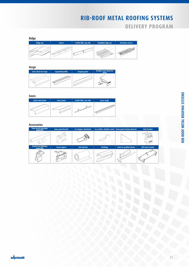
RidgeRidge cap Closure Profile filler, top side ventilation ridge cap ventilation closure
vergeCover sheet for verge Suspended profile Stopping plate variable cover sheet for
verge
EavesGutter inlet sheet Eaves panel Profile filler, rear side Eaves angle
AccessoriesSnow guard pipe/pipe
connector Snow guard bracket Ice stopper, aluminium Ice catcher, stainless-steel Snow guard raising element Solar bracket
Bracket for lightning protection Tread support Coil material Flashings Tools for profiled sheets Fall arrest system
RIB-
ROOF
MET
AL R
OOFI
NG S
YSTE
MS

26
RIB-ROOF METAL ROOFING SYSTEMSTAPERED, CURvED, TAPERED CURvED PROFILED SHEETS
TAPERED, CURVED AND TAPERED CURVED PROFILED SHEETS
TAPERED PROFILED SHEETS
RIB-ROOF profiled sheets are also available tapered, curved or tapered curved. Tapered profiled sheets with a minimum construction width of 230 mm and a maximum standard width of 500 mm are executable. Apart from the standard width of 500 mm, we are prepared to manufacture other construction widths, e.g. 333 mm, 400 mm or up to 600 mm as a maximum, upon request.
2.8
2.8.1
Table of minimum bending radii
CURVED PROFILED SHEETS2.8.2
Depending on the material and material thickness (t in mm) when curving with machines, the following minimum bending radii have to be observed:
Minimum bending radii with RIB-ROOF Speed 500
Material convex concave Material thickness t Radius Radius
[mm] [m] [m]Steel 0.63 4.00 10.00
Aluminium 1.00 1.00 10.00Aluminium 0.90 5.00 10.00Aluminium 0.80 10.00 -
Titanium zinc 1.00 on request on requestCopper 0.60 on request on request
Minimum bending radii with RIB-ROOF 465
Material convex concave Material thickness t Radius Radius
[mm] [m] [m]Steel 0.63 6.00 20.00
Aluminium 1.00 6.00 20.00Aluminium 0.90 10.00 20.00Aluminium 0.80 15.00 -
Titanium zinc 1.00 on request on requestCopper 0.60 on request on request
Please contact us in advance if you intend to order curved profiled sheets with low bending radii. RIB-ROOF Speed 500 profiled sheets with a radius over 100 m will be curved without any machines but forced-curved and installed with standard clips. Turned clips have to be used with radii less than 100 m (installation direction is from right to left).
Please contact us in advance if you intend to order curved profiled sheets with low bending radii. RIB-ROOF 465 profiled sheets can alternatively be forced-curved so that low bending radii are possible. RIB-ROOF 465 profiled sheets can also be curved without any machi-nes with a radius over 60 m but forced-curved.
Speed 500
465
Speed 500
In general: As the profiled sheets have to be pressed onto the requested radius when carrying out force-curving, waves are possible. Therefore, curving with machines is the optically better solution.
Table of minimum bending radii
27
RIB-ROOF METAL ROOFING SYSTEMSTAPERD, CURvED, TAPERED CURvED PROFILED SHEETS
RIB-ROOF METAL ROOFING SYSTEMSTAPERED, CURvED, TAPERED CURvED PROFILED SHEETS
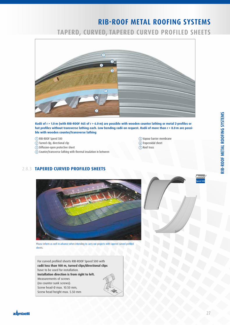
Radii of r > 1.0 m (with RIB-ROOF 465 of r > 6.0 m) are possible with wooden counter lathing or metal Z-profiles or hat profiles without transverse lathing each. Low bending radii on request. Radii of more than r > 8.0 m are possi-ble with wooden counter/transverse lathing
For curved profiled sheets RIB-ROOF Speed 500 with radii less than 100 m, turned clips/directional clips have to be used for installation. Installation direction is from right to left.Measurements of screws (no counter-sunk screws): Screw head-Ø max. 10.50 mm, Screw head height max. 5.50 mm
TAPERED CURVED PROFILED SHEETS2.8.3
Please inform us well in advance when intending to carry out projects with tapered curved profiled sheets.
Speed 500
1 RIB-ROOF Speed 5002 Turned clip, directional clip3 Diffusion-open protective sheet4 Counter/transverse lathing with thermal insulation in between
5 Vapour barrier membrane6 Trapezoidal sheet7 Roof truss
1
23
4
5
6
7
RIB-
ROOF
MET
AL R
OOFI
NG S
YSTE
MS
28
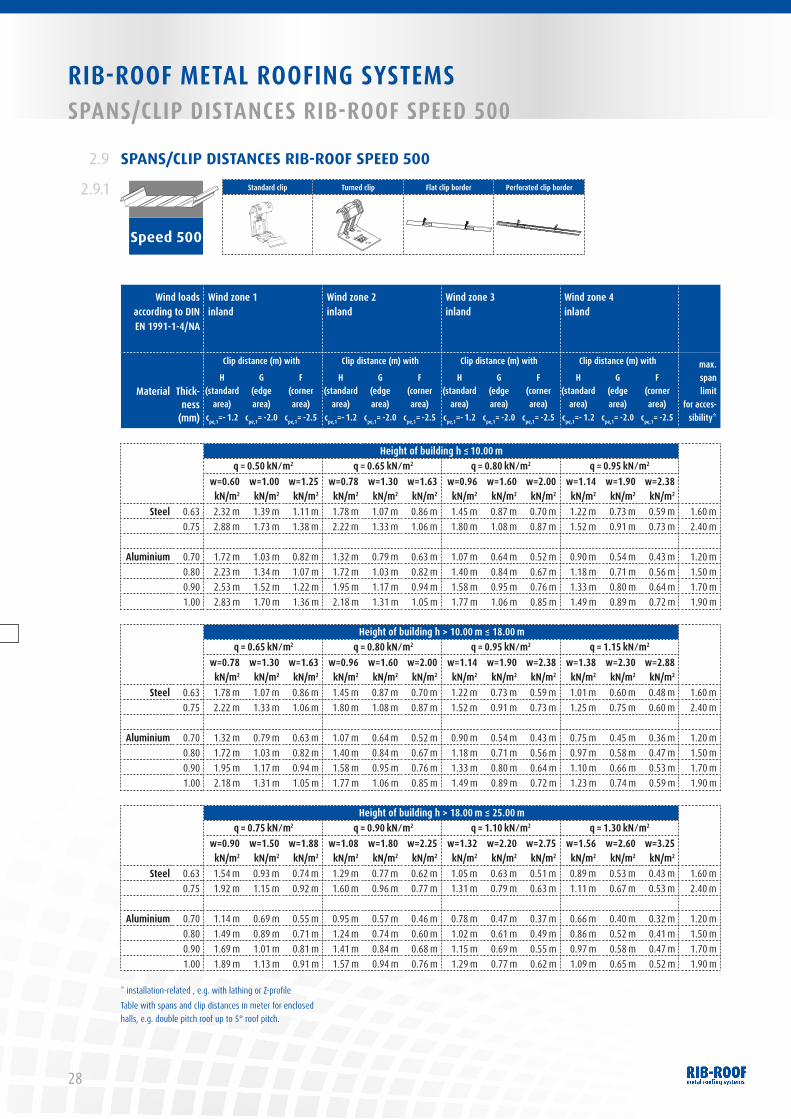
RIB-ROOF METAL ROOFING SYSTEMSSPANS/CLIP DISTANCES RIB-ROOF SPEED 500
Wind loads according to DIN EN 1991-1-4/NA
Wind zone 1inland
Wind zone 2 inland
Wind zone 3 inland
Wind zone 4 inland
Thick-ness
(mm)
Clip distance (m) with Clip distance (m) with Clip distance (m) with Clip distance (m) with max. span limit
for acces-sibility*
MaterialH
(standard area)
cpe,1=- 1.2
G (edge area)
cpe,1= -2.0
F (corner area)
cpe,1= -2.5
H (standard
area)cpe,1=- 1.2
G (edge area)
cpe,1= -2.0
F (corner area)
cpe,1= -2.5
H (standard
area)cpe,1=- 1.2
G (edge area)
cpe,1= -2.0
F (corner area)
cpe,1= -2.5
H (standard
area)cpe,1=- 1.2
G (edge area)
cpe,1= -2.0
F (corner area)
cpe,1= -2.5
Height of building h ≤ 10.00 m q = 0.50 kN ⁄ m2 q = 0.65 kN ⁄ m2 q = 0.80 kN ⁄ m2 q = 0.95 kN ⁄ m2
w=0.60 kN/m2
w=1.00 kN/m2
w=1.25 kN/m2
w=0.78 kN/m2
w=1.30 kN/m2
w=1.63 kN/m2
w=0.96 kN/m2
w=1.60 kN/m2
w=2.00 kN/m2
w=1.14 kN/m2
w=1.90 kN/m2
w=2.38 kN/m2
Steel 0.63 2.32 m 1.39 m 1.11 m 1.78 m 1.07 m 0.86 m 1.45 m 0.87 m 0.70 m 1.22 m 0.73 m 0.59 m 1.60 m 0.75 2.88 m 1.73 m 1.38 m 2.22 m 1.33 m 1.06 m 1.80 m 1.08 m 0.87 m 1.52 m 0.91 m 0.73 m 2.40 m
Aluminium 0.70 1.72 m 1.03 m 0.82 m 1.32 m 0.79 m 0.63 m 1.07 m 0.64 m 0.52 m 0.90 m 0.54 m 0.43 m 1.20 m0.80 2.23 m 1.34 m 1.07 m 1.72 m 1.03 m 0.82 m 1.40 m 0.84 m 0.67 m 1.18 m 0.71 m 0.56 m 1.50 m0.90 2.53 m 1.52 m 1.22 m 1.95 m 1.17 m 0.94 m 1.58 m 0.95 m 0.76 m 1.33 m 0.80 m 0.64 m 1.70 m1.00 2.83 m 1.70 m 1.36 m 2.18 m 1.31 m 1.05 m 1.77 m 1.06 m 0.85 m 1.49 m 0.89 m 0.72 m 1.90 m
Height of building h > 10.00 m ≤ 18.00 mq = 0.65 kN ⁄ m2 q = 0.80 kN ⁄ m2 q = 0.95 kN ⁄ m2 q = 1.15 kN ⁄ m2
w=0.78 kN/m2
w=1.30 kN/m2
w=1.63 kN/m2
w=0.96 kN/m2
w=1.60 kN/m2
w=2.00 kN/m2
w=1.14 kN/m2
w=1.90 kN/m2
w=2.38 kN/m2
w=1.38 kN/m2
w=2.30 kN/m2
w=2.88 kN/m2
Steel 0.63 1.78 m 1.07 m 0.86 m 1.45 m 0.87 m 0.70 m 1.22 m 0.73 m 0.59 m 1.01 m 0.60 m 0.48 m 1.60 m 0.75 2.22 m 1.33 m 1.06 m 1.80 m 1.08 m 0.87 m 1.52 m 0.91 m 0.73 m 1.25 m 0.75 m 0.60 m 2.40 m
Aluminium 0.70 1.32 m 0.79 m 0.63 m 1.07 m 0.64 m 0.52 m 0.90 m 0.54 m 0.43 m 0.75 m 0.45 m 0.36 m 1.20 m0.80 1.72 m 1.03 m 0.82 m 1.40 m 0.84 m 0.67 m 1.18 m 0.71 m 0.56 m 0.97 m 0.58 m 0.47 m 1.50 m0.90 1.95 m 1.17 m 0.94 m 1.58 m 0.95 m 0.76 m 1.33 m 0.80 m 0.64 m 1.10 m 0.66 m 0.53 m 1.70 m1.00 2.18 m 1.31 m 1.05 m 1.77 m 1.06 m 0.85 m 1.49 m 0.89 m 0.72 m 1.23 m 0.74 m 0.59 m 1.90 m
Height of building h > 18.00 m ≤ 25.00 mq = 0.75 kN ⁄ m2 q = 0.90 kN ⁄ m2 q = 1.10 kN ⁄ m2 q = 1.30 kN ⁄ m2
w=0.90 kN/m2
w=1.50 kN/m2
w=1.88 kN/m2
w=1.08 kN/m2
w=1.80 kN/m2
w=2.25 kN/m2
w=1.32 kN/m2
w=2.20 kN/m2
w=2.75 kN/m2
w=1.56 kN/m2
w=2.60 kN/m2
w=3.25 kN/m2
Steel 0.63 1.54 m 0.93 m 0.74 m 1.29 m 0.77 m 0.62 m 1.05 m 0.63 m 0.51 m 0.89 m 0.53 m 0.43 m 1.60 m 0.75 1.92 m 1.15 m 0.92 m 1.60 m 0.96 m 0.77 m 1.31 m 0.79 m 0.63 m 1.11 m 0.67 m 0.53 m 2.40 m
Aluminium 0.70 1.14 m 0.69 m 0.55 m 0.95 m 0.57 m 0.46 m 0.78 m 0.47 m 0.37 m 0.66 m 0.40 m 0.32 m 1.20 m0.80 1.49 m 0.89 m 0.71 m 1.24 m 0.74 m 0.60 m 1.02 m 0.61 m 0.49 m 0.86 m 0.52 m 0.41 m 1.50 m0.90 1.69 m 1.01 m 0.81 m 1.41 m 0.84 m 0.68 m 1.15 m 0.69 m 0.55 m 0.97 m 0.58 m 0.47 m 1.70 m1.00 1.89 m 1.13 m 0.91 m 1.57 m 0.94 m 0.76 m 1.29 m 0.77 m 0.62 m 1.09 m 0.65 m 0.52 m 1.90 m
* installation-related , e.g. with lathing or Z-profileTable with spans and clip distances in meter for enclosed halls, e.g. double pitch roof up to 5° roof pitch.
SPANS/CLIP DISTANCES RIB-ROOF SPEED 500 2.9
2.9.1
Speed 500
Standard clip Turned clip Flat clip border Perforated clip border
29
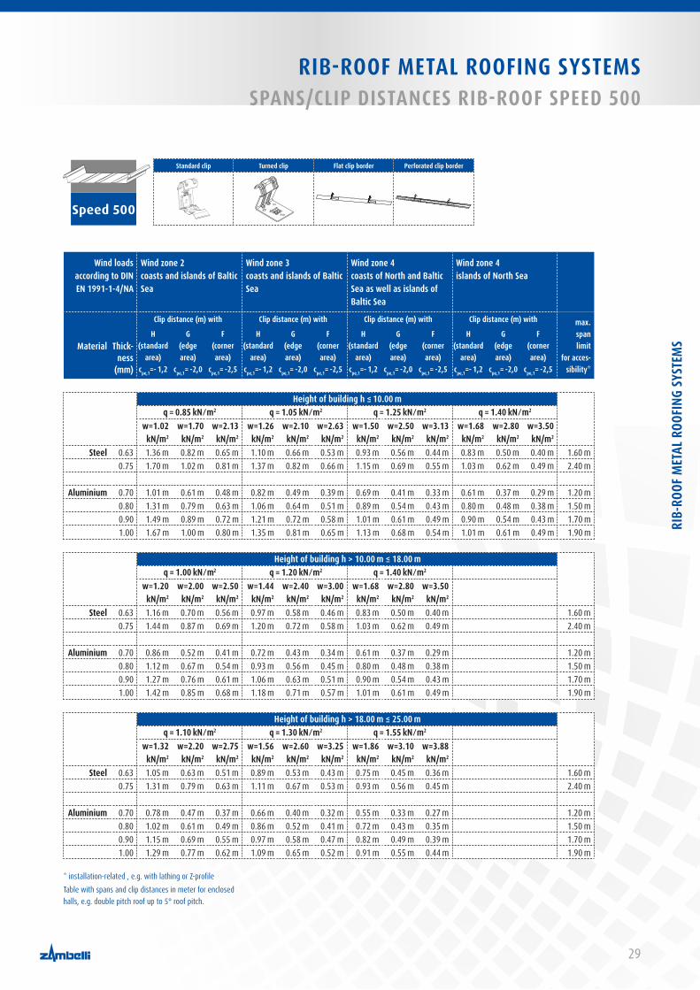
RIB-ROOF METAL ROOFING SYSTEMS SPANS/CLIP DISTANCES RIB-ROOF SPEED 500
Wind loads according to DIN EN 1991-1-4/NA
Wind zone 2coasts and islands of Baltic Sea
Wind zone 3coasts and islands of Baltic Sea
Wind zone 4coasts of North and Baltic Sea as well as islands of Baltic Sea
Wind zone 4islands of North Sea
Thick-ness
(mm)
Clip distance (m) with Clip distance (m) with Clip distance (m) with Clip distance (m) with max. span limit
for acces-sibility*
MaterialH
(standard area)
cpe,1=- 1,2
G (edge area)
cpe,1= -2,0
F (corner area)
cpe,1= -2,5
H (standard
area)cpe,1=- 1,2
G (edge area)
cpe,1= -2,0
F (corner area)
cpe,1= -2,5
H (standard
area)cpe,1=- 1,2
G (edge area)
cpe,1= -2,0
F (corner area)
cpe,1= -2,5
H (standard
area)cpe,1=- 1,2
G (edge area)
cpe,1= -2,0
F (corner area)
cpe,1= -2,5
Height of building h ≤ 10.00 m q = 0.85 kN ⁄ m2 q = 1.05 kN ⁄ m2 q = 1.25 kN ⁄ m2 q = 1.40 kN ⁄ m2
w=1.02 kN/m2
w=1.70 kN/m2
w=2.13 kN/m2
w=1.26 kN/m2
w=2.10 kN/m2
w=2.63 kN/m2
w=1.50 kN/m2
w=2.50 kN/m2
w=3.13 kN/m2
w=1.68 kN/m2
w=2.80kN/m2
w=3.50 kN/m2
Steel 0.63 1.36 m 0.82 m 0.65 m 1.10 m 0.66 m 0.53 m 0.93 m 0.56 m 0.44 m 0.83 m 0.50 m 0.40 m 1.60 m 0.75 1.70 m 1.02 m 0.81 m 1.37 m 0.82 m 0.66 m 1.15 m 0.69 m 0.55 m 1.03 m 0.62 m 0.49 m 2.40 m
Aluminium 0.70 1.01 m 0.61 m 0.48 m 0.82 m 0.49 m 0.39 m 0.69 m 0.41 m 0.33 m 0.61 m 0.37 m 0.29 m 1.20 m0.80 1.31 m 0.79 m 0.63 m 1.06 m 0.64 m 0.51 m 0.89 m 0.54 m 0.43 m 0.80 m 0.48 m 0.38 m 1.50 m0.90 1.49 m 0.89 m 0.72 m 1.21 m 0.72 m 0.58 m 1.01 m 0.61 m 0.49 m 0.90 m 0.54 m 0.43 m 1.70 m1.00 1.67 m 1.00 m 0.80 m 1.35 m 0.81 m 0.65 m 1.13 m 0.68 m 0.54 m 1.01 m 0.61 m 0.49 m 1.90 m
Height of building h > 10.00 m ≤ 18.00 mq = 1.00 kN ⁄ m2 q = 1.20 kN ⁄ m2 q = 1.40 kN ⁄ m2
w=1.20 kN/m2
w=2.00 kN/m2
w=2.50 kN/m2
w=1.44 kN/m2
w=2.40 kN/m2
w=3.00 kN/m2
w=1.68 kN/m2
w=2.80 kN/m2
w=3.50 kN/m2
Steel 0.63 1.16 m 0.70 m 0.56 m 0.97 m 0.58 m 0.46 m 0.83 m 0.50 m 0.40 m 1.60 m 0.75 1.44 m 0.87 m 0.69 m 1.20 m 0.72 m 0.58 m 1.03 m 0.62 m 0.49 m 2.40 m
Aluminium 0.70 0.86 m 0.52 m 0.41 m 0.72 m 0.43 m 0.34 m 0.61 m 0.37 m 0.29 m 1.20 m0.80 1.12 m 0.67 m 0.54 m 0.93 m 0.56 m 0.45 m 0.80 m 0.48 m 0.38 m 1.50 m0.90 1.27 m 0.76 m 0.61 m 1.06 m 0.63 m 0.51 m 0.90 m 0.54 m 0.43 m 1.70 m1.00 1.42 m 0.85 m 0.68 m 1.18 m 0.71 m 0.57 m 1.01 m 0.61 m 0.49 m 1.90 m
Height of building h > 18.00 m ≤ 25.00 mq = 1.10 kN ⁄ m2 q = 1.30 kN ⁄ m2 q = 1.55 kN ⁄ m2
w=1.32 kN/m2
w=2.20 kN/m2
w=2.75 kN/m2
w=1.56 kN/m2
w=2.60 kN/m2
w=3.25 kN/m2
w=1.86 kN/m2
w=3.10 kN/m2
w=3.88 kN/m2
Steel 0.63 1.05 m 0.63 m 0.51 m 0.89 m 0.53 m 0.43 m 0.75 m 0.45 m 0.36 m 1.60 m 0.75 1.31 m 0.79 m 0.63 m 1.11 m 0.67 m 0.53 m 0.93 m 0.56 m 0.45 m 2.40 m
Aluminium 0.70 0.78 m 0.47 m 0.37 m 0.66 m 0.40 m 0.32 m 0.55 m 0.33 m 0.27 m 1.20 m0.80 1.02 m 0.61 m 0.49 m 0.86 m 0.52 m 0.41 m 0.72 m 0.43 m 0.35 m 1.50 m0.90 1.15 m 0.69 m 0.55 m 0.97 m 0.58 m 0.47 m 0.82 m 0.49 m 0.39 m 1.70 m1.00 1.29 m 0.77 m 0.62 m 1.09 m 0.65 m 0.52 m 0.91 m 0.55 m 0.44 m 1.90 m
* installation-related , e.g. with lathing or Z-profileTable with spans and clip distances in meter for enclosed halls, e.g. double pitch roof up to 5° roof pitch.
Speed 500
Standard clip Turned clip Flat clip border Perforated clip border
RIB-
ROOF
MET
AL R
OOFI
NG S
YSTE
MS
30
RIB-ROOF METAL ROOFING SYSTEMSSPANS/CLIP DISTANCES RIB-ROOF SPEED 500
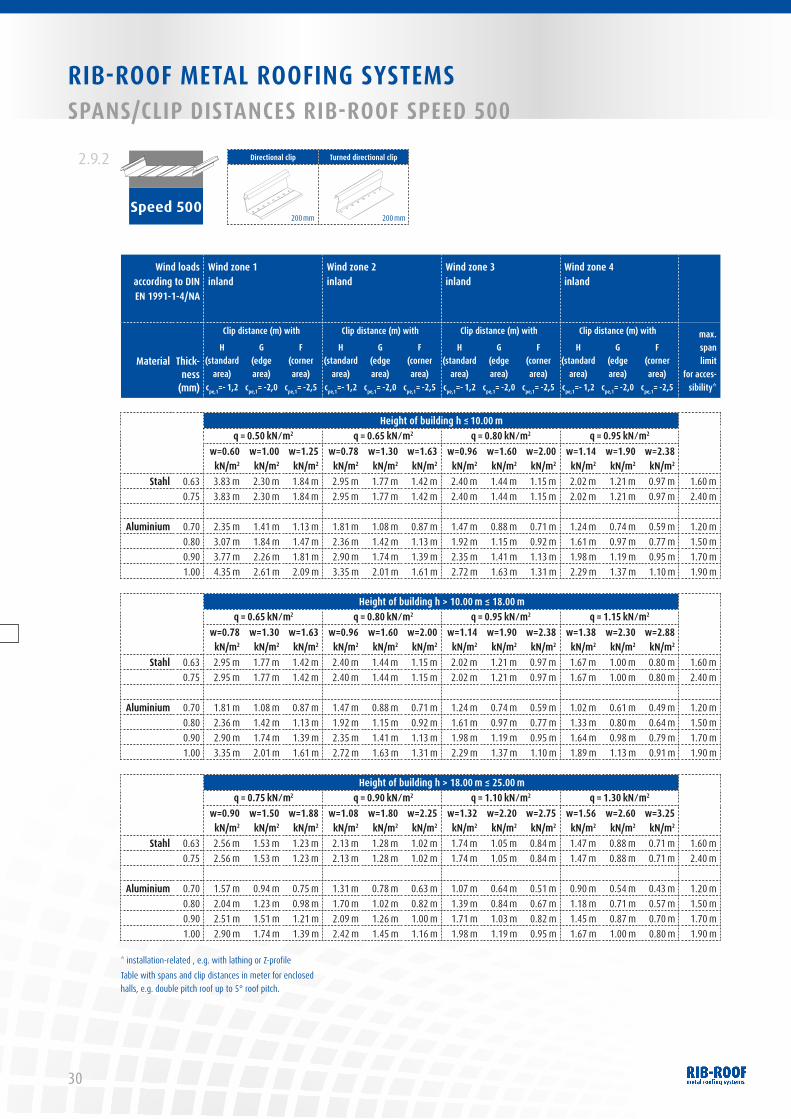
2.9.2
Speed 500
Directional clip Turned directional clip
200 mm 200 mm
Wind loads according to DIN EN 1991-1-4/NA
Wind zone 1inland
Wind zone 2 inland
Wind zone 3 inland
Wind zone 4 inland
Thick-ness
(mm)
Clip distance (m) with Clip distance (m) with Clip distance (m) with Clip distance (m) with max. span limit
for acces-sibility*
MaterialH
(standard area)
cpe,1=- 1,2
G (edge area)
cpe,1= -2,0
F (corner area)
cpe,1= -2,5
H (standard
area)cpe,1=- 1,2
G (edge area)
cpe,1= -2,0
F (corner area)
cpe,1= -2,5
H (standard
area)cpe,1=- 1,2
G (edge area)
cpe,1= -2,0
F (corner area)
cpe,1= -2,5
H (standard
area)cpe,1=- 1,2
G (edge area)
cpe,1= -2,0
F (corner area)
cpe,1= -2,5
Height of building h ≤ 10.00 m q = 0.50 kN ⁄ m2 q = 0.65 kN ⁄ m2 q = 0.80 kN ⁄ m2 q = 0.95 kN ⁄ m2
w=0.60 kN/m2
w=1.00 kN/m2
w=1.25 kN/m2
w=0.78 kN/m2
w=1.30 kN/m2
w=1.63 kN/m2
w=0.96 kN/m2
w=1.60 kN/m2
w=2.00 kN/m2
w=1.14 kN/m2
w=1.90 kN/m2
w=2.38 kN/m2
Stahl 0.63 3.83 m 2.30 m 1.84 m 2.95 m 1.77 m 1.42 m 2.40 m 1.44 m 1.15 m 2.02 m 1.21 m 0.97 m 1.60 m 0.75 3.83 m 2.30 m 1.84 m 2.95 m 1.77 m 1.42 m 2.40 m 1.44 m 1.15 m 2.02 m 1.21 m 0.97 m 2.40 m
Aluminium 0.70 2.35 m 1.41 m 1.13 m 1.81 m 1.08 m 0.87 m 1.47 m 0.88 m 0.71 m 1.24 m 0.74 m 0.59 m 1.20 m0.80 3.07 m 1.84 m 1.47 m 2.36 m 1.42 m 1.13 m 1.92 m 1.15 m 0.92 m 1.61 m 0.97 m 0.77 m 1.50 m0.90 3.77 m 2.26 m 1.81 m 2.90 m 1.74 m 1.39 m 2.35 m 1.41 m 1.13 m 1.98 m 1.19 m 0.95 m 1.70 m1.00 4.35 m 2.61 m 2.09 m 3.35 m 2.01 m 1.61 m 2.72 m 1.63 m 1.31 m 2.29 m 1.37 m 1.10 m 1.90 m
Height of building h > 10.00 m ≤ 18.00 mq = 0.65 kN ⁄ m2 q = 0.80 kN ⁄ m2 q = 0.95 kN ⁄ m2 q = 1.15 kN ⁄ m2
w=0.78 kN/m2
w=1.30 kN/m2
w=1.63 kN/m2
w=0.96 kN/m2
w=1.60 kN/m2
w=2.00 kN/m2
w=1.14 kN/m2
w=1.90 kN/m2
w=2.38 kN/m2
w=1.38 kN/m2
w=2.30 kN/m2
w=2.88 kN/m2
Stahl 0.63 2.95 m 1.77 m 1.42 m 2.40 m 1.44 m 1.15 m 2.02 m 1.21 m 0.97 m 1.67 m 1.00 m 0.80 m 1.60 m 0.75 2.95 m 1.77 m 1.42 m 2.40 m 1.44 m 1.15 m 2.02 m 1.21 m 0.97 m 1.67 m 1.00 m 0.80 m 2.40 m
Aluminium 0.70 1.81 m 1.08 m 0.87 m 1.47 m 0.88 m 0.71 m 1.24 m 0.74 m 0.59 m 1.02 m 0.61 m 0.49 m 1.20 m0.80 2.36 m 1.42 m 1.13 m 1.92 m 1.15 m 0.92 m 1.61 m 0.97 m 0.77 m 1.33 m 0.80 m 0.64 m 1.50 m0.90 2.90 m 1.74 m 1.39 m 2.35 m 1.41 m 1.13 m 1.98 m 1.19 m 0.95 m 1.64 m 0.98 m 0.79 m 1.70 m1.00 3.35 m 2.01 m 1.61 m 2.72 m 1.63 m 1.31 m 2.29 m 1.37 m 1.10 m 1.89 m 1.13 m 0.91 m 1.90 m
Height of building h > 18.00 m ≤ 25.00 mq = 0.75 kN ⁄ m2 q = 0.90 kN ⁄ m2 q = 1.10 kN ⁄ m2 q = 1.30 kN ⁄ m2
w=0.90 kN/m2
w=1.50 kN/m2
w=1.88 kN/m2
w=1.08 kN/m2
w=1.80 kN/m2
w=2.25 kN/m2
w=1.32 kN/m2
w=2.20 kN/m2
w=2.75 kN/m2
w=1.56 kN/m2
w=2.60 kN/m2
w=3.25 kN/m2
Stahl 0.63 2.56 m 1.53 m 1.23 m 2.13 m 1.28 m 1.02 m 1.74 m 1.05 m 0.84 m 1.47 m 0.88 m 0.71 m 1.60 m 0.75 2.56 m 1.53 m 1.23 m 2.13 m 1.28 m 1.02 m 1.74 m 1.05 m 0.84 m 1.47 m 0.88 m 0.71 m 2.40 m
Aluminium 0.70 1.57 m 0.94 m 0.75 m 1.31 m 0.78 m 0.63 m 1.07 m 0.64 m 0.51 m 0.90 m 0.54 m 0.43 m 1.20 m0.80 2.04 m 1.23 m 0.98 m 1.70 m 1.02 m 0.82 m 1.39 m 0.84 m 0.67 m 1.18 m 0.71 m 0.57 m 1.50 m0.90 2.51 m 1.51 m 1.21 m 2.09 m 1.26 m 1.00 m 1.71 m 1.03 m 0.82 m 1.45 m 0.87 m 0.70 m 1.70 m1.00 2.90 m 1.74 m 1.39 m 2.42 m 1.45 m 1.16 m 1.98 m 1.19 m 0.95 m 1.67 m 1.00 m 0.80 m 1.90 m
* installation-related , e.g. with lathing or Z-profileTable with spans and clip distances in meter for enclosed halls, e.g. double pitch roof up to 5° roof pitch.
31
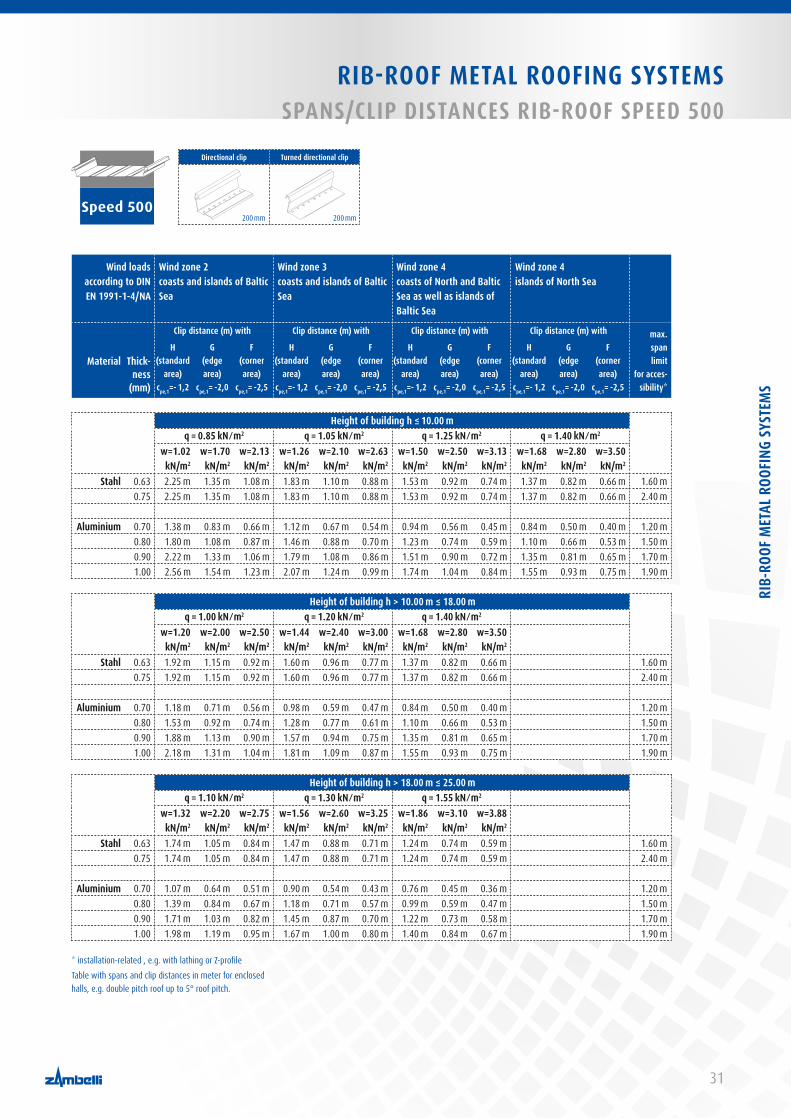
RIB-ROOF METAL ROOFING SYSTEMS SPANS/CLIP DISTANCES RIB-ROOF SPEED 500
Speed 500
Directional clip Turned directional clip
Wind loads according to DIN EN 1991-1-4/NA
Wind zone 2coasts and islands of Baltic Sea
Wind zone 3coasts and islands of Baltic Sea
Wind zone 4coasts of North and Baltic Sea as well as islands of Baltic Sea
Wind zone 4islands of North Sea
Thick-ness
(mm)
Clip distance (m) with Clip distance (m) with Clip distance (m) with Clip distance (m) with max. span limit
for acces-sibility*
MaterialH
(standard area)
cpe,1=- 1,2
G (edge area)
cpe,1= -2,0
F (corner area)
cpe,1= -2,5
H (standard
area)cpe,1=- 1,2
G (edge area)
cpe,1= -2,0
F (corner area)
cpe,1= -2,5
H (standard
area)cpe,1=- 1,2
G (edge area)
cpe,1= -2,0
F (corner area)
cpe,1= -2,5
H (standard
area)cpe,1=- 1,2
G (edge area)
cpe,1= -2,0
F (corner area)
cpe,1= -2,5
Height of building h ≤ 10.00 m q = 0.85 kN ⁄ m2 q = 1.05 kN ⁄ m2 q = 1.25 kN ⁄ m2 q = 1.40 kN ⁄ m2
w=1.02 kN/m2
w=1.70 kN/m2
w=2.13 kN/m2
w=1.26 kN/m2
w=2.10 kN/m2
w=2.63 kN/m2
w=1.50 kN/m2
w=2.50 kN/m2
w=3.13 kN/m2
w=1.68 kN/m2
w=2.80kN/m2
w=3.50 kN/m2
Stahl 0.63 2.25 m 1.35 m 1.08 m 1.83 m 1.10 m 0.88 m 1.53 m 0.92 m 0.74 m 1.37 m 0.82 m 0.66 m 1.60 m 0.75 2.25 m 1.35 m 1.08 m 1.83 m 1.10 m 0.88 m 1.53 m 0.92 m 0.74 m 1.37 m 0.82 m 0.66 m 2.40 m
Aluminium 0.70 1.38 m 0.83 m 0.66 m 1.12 m 0.67 m 0.54 m 0.94 m 0.56 m 0.45 m 0.84 m 0.50 m 0.40 m 1.20 m0.80 1.80 m 1.08 m 0.87 m 1.46 m 0.88 m 0.70 m 1.23 m 0.74 m 0.59 m 1.10 m 0.66 m 0.53 m 1.50 m0.90 2.22 m 1.33 m 1.06 m 1.79 m 1.08 m 0.86 m 1.51 m 0.90 m 0.72 m 1.35 m 0.81 m 0.65 m 1.70 m1.00 2.56 m 1.54 m 1.23 m 2.07 m 1.24 m 0.99 m 1.74 m 1.04 m 0.84 m 1.55 m 0.93 m 0.75 m 1.90 m
Height of building h > 10.00 m ≤ 18.00 mq = 1.00 kN ⁄ m2 q = 1.20 kN ⁄ m2 q = 1.40 kN ⁄ m2
w=1.20 kN/m2
w=2.00 kN/m2
w=2.50 kN/m2
w=1.44 kN/m2
w=2.40 kN/m2
w=3.00 kN/m2
w=1.68 kN/m2
w=2.80 kN/m2
w=3.50 kN/m2
Stahl 0.63 1.92 m 1.15 m 0.92 m 1.60 m 0.96 m 0.77 m 1.37 m 0.82 m 0.66 m 1.60 m 0.75 1.92 m 1.15 m 0.92 m 1.60 m 0.96 m 0.77 m 1.37 m 0.82 m 0.66 m 2.40 m
Aluminium 0.70 1.18 m 0.71 m 0.56 m 0.98 m 0.59 m 0.47 m 0.84 m 0.50 m 0.40 m 1.20 m0.80 1.53 m 0.92 m 0.74 m 1.28 m 0.77 m 0.61 m 1.10 m 0.66 m 0.53 m 1.50 m0.90 1.88 m 1.13 m 0.90 m 1.57 m 0.94 m 0.75 m 1.35 m 0.81 m 0.65 m 1.70 m1.00 2.18 m 1.31 m 1.04 m 1.81 m 1.09 m 0.87 m 1.55 m 0.93 m 0.75 m 1.90 m
Height of building h > 18.00 m ≤ 25.00 mq = 1.10 kN ⁄ m2 q = 1.30 kN ⁄ m2 q = 1.55 kN ⁄ m2
w=1.32 kN/m2
w=2.20 kN/m2
w=2.75 kN/m2
w=1.56 kN/m2
w=2.60 kN/m2
w=3.25 kN/m2
w=1.86 kN/m2
w=3.10 kN/m2
w=3.88 kN/m2
Stahl 0.63 1.74 m 1.05 m 0.84 m 1.47 m 0.88 m 0.71 m 1.24 m 0.74 m 0.59 m 1.60 m 0.75 1.74 m 1.05 m 0.84 m 1.47 m 0.88 m 0.71 m 1.24 m 0.74 m 0.59 m 2.40 m
Aluminium 0.70 1.07 m 0.64 m 0.51 m 0.90 m 0.54 m 0.43 m 0.76 m 0.45 m 0.36 m 1.20 m0.80 1.39 m 0.84 m 0.67 m 1.18 m 0.71 m 0.57 m 0.99 m 0.59 m 0.47 m 1.50 m0.90 1.71 m 1.03 m 0.82 m 1.45 m 0.87 m 0.70 m 1.22 m 0.73 m 0.58 m 1.70 m1.00 1.98 m 1.19 m 0.95 m 1.67 m 1.00 m 0.80 m 1.40 m 0.84 m 0.67 m 1.90 m
* installation-related , e.g. with lathing or Z-profileTable with spans and clip distances in meter for enclosed halls, e.g. double pitch roof up to 5° roof pitch.
200 mm 200 mm
RIB-
ROOF
MET
AL R
OOFI
NG S
YSTE
MS

32
RIB-ROOF METAL ROOFING SYSTEMSSPANS/CLIP DISTANCES RIB-ROOF SPEED 500
2.9.3
Speed 500
Directional profile Turned directional profile
750 mm 1500 mm
750 mm 1500 mm
Wind loads according to DIN EN 1991-1-4/NA
Wind zone 1inland
Wind zone 2 inland
Wind zone 3 inland
Wind zone 4 inland
Thick-ness
(mm)
Clip distance (m) with Clip distance (m) with Clip distance (m) with Clip distance (m) with max. span limit
for acces-sibility*
MaterialH
(standard area)
cpe,1=- 1,2
G (edge area)
cpe,1= -2,0
F (corner area)
cpe,1= -2,5
H (standard
area)cpe,1=- 1,2
G (edge area)
cpe,1= -2,0
F (corner area)
cpe,1= -2,5
H (standard
area)cpe,1=- 1,2
G (edge area)
cpe,1= -2,0
F (corner area)
cpe,1= -2,5
H (standard
area)cpe,1=- 1,2
G (edge area)
cpe,1= -2,0
F (corner area)
cpe,1= -2,5
Height of building h ≤ 10.00 m q = 0.50 kN ⁄ m2 q = 0.65 kN ⁄ m2 q = 0.80 kN ⁄ m2 q = 0.95 kN ⁄ m2
w=0.60 kN/m2
w=1.00 kN/m2
w=1.25 kN/m2
w=0.78 kN/m2
w=1.30 kN/m2
w=1.63 kN/m2
w=0.96 kN/m2
w=1.60 kN/m2
w=2.00 kN/m2
w=1.14 kN/m2
w=1.90 kN/m2
w=2.38 kN/m2
Steel 0.63 5.73 m 3.44 m 2.75 m 4.41 m 2.65 m 2.12 m 3.58 m 2.15 m 1.72 m 3.02 m 1.81 m 1.45 m 1.60 m 0.75 5.73 m 3.44 m 2.75 m 4.41 m 2.65 m 2.12 m 3.58 m 2.15 m 1.72 m 3.02 m 1.81 m 1.45 m 2.40 m
Aluminium 0.70 3.55 m 2.13 m 1.70 m 2.73 m 1.64 m 1.31 m 2.22 m 1.33 m 1.07 m 1.87 m 1.12 m 0.90 m 1.20 m0.80 4.63 m 2.78 m 2.22 m 3.56 m 2.14 m 1.71 m 2.90 m 1.74 m 1.39 m 2.44 m 1.46 m 1.17 m 1.50 m0.90 5.43 m 3.26 m 2.61 m 4.18 m 2.51 m 2.01 m 3.40 m 2.04 m 1.63 m 2.86 m 1.72 m 1.37 m 1.70 m1.00 6.10 m 3.66 m 2.93 m 4.69 m 2.82 m 2.25 m 3.81 m 2.29 m 1.83 m 3.21 m 1.93 m 1.54 m 1.90 m
Height of building h > 10.00 m ≤ 18.00 mq = 0.65 kN ⁄ m2 q = 0.80 kN ⁄ m2 q = 0.95 kN ⁄ m2 q = 1.15 kN ⁄ m2
w=0.78 kN/m2
w=1.30 kN/m2
w=1.63 kN/m2
w=0.96 kN/m2
w=1.60 kN/m2
w=2.00 kN/m2
w=1.14 kN/m2
w=1.90 kN/m2
w=2.38 kN/m2
w=1.38 kN/m2
w=2.30 kN/m2
w=2.88 kN/m2
Steel 0.63 4.41 m 2.65 m 2.12 m 3.58 m 2.15 m 1.72 m 3.02 m 1.81 m 1.45 m 2.49 m 1.50 m 1.20 m 1.60 m 0.75 4.41 m 2.65 m 2.12 m 3.58 m 2.15 m 1.72 m 3.02 m 1.81 m 1.45 m 2.49 m 1.50 m 1.20 m 2.40 m
Aluminium 0.70 2.73 m 1.64 m 1.31 m 2.22 m 1.33 m 1.07 m 1.87 m 1.12 m 0.90 m 1.54 m 0.93 m 0.74 m 1.20 m0.80 3.56 m 2.14 m 1.71 m 2.90 m 1.74 m 1.39 m 2.44 m 1.46 m 1.17 m 2.01 m 1.21 m 0.97 m 1.50 m0.90 4.18 m 2.51 m 2.01 m 3.40 m 2.04 m 1.63 m 2.86 m 1.72 m 1.37 m 2.36 m 1.42 m 1.13 m 1.70 m1.00 4.69 m 2.82 m 2.25 m 3.81 m 2.29 m 1.83 m 3.21 m 1.93 m 1.54 m 2.65 m 1.59 m 1.27 m 1.90 m
Height of building h > 18.00 m ≤ 25.00 mq = 0.75 kN ⁄ m2 q = 0.90 kN ⁄ m2 q = 1.10 kN ⁄ m2 q = 1.30 kN ⁄ m2
w=0.90 kN/m2
w=1.50 kN/m2
w=1.88 kN/m2
w=1.08 kN/m2
w=1.80 kN/m2
w=2.25 kN/m2
w=1.32 kN/m2
w=2.20 kN/m2
w=2.75 kN/m2
w=1.56 kN/m2
w=2.60 kN/m2
w=3.25 kN/m2
Steel 0.63 3.82 m 2.29 m 1.83 m 3.19 m 1.91 m 1.53 m 2.61 m 1.56 m 1.25 m 2.21 m 1.32 m 1.06 m 1.60 m 0.75 3.82 m 2.29 m 1.83 m 3.19 m 1.91 m 1.53 m 2.61 m 1.56 m 1.25 m 2.21 m 1.32 m 1.06 m 2.40 m
Aluminium 0.70 2.37 m 1.42 m 1.14 m 1.97 m 1.18 m 0.95 m 1.61 m 0.97 m 0.77 m 1.37 m 0.82 m 0.66 m 1.20 m0.80 3.09 m 1.85 m 1.48 m 2.57 m 1.54 m 1.24 m 2.11 m 1.26 m 1.01 m 1.78 m 1.07 m 0.86 m 1.50 m0.90 3.62 m 2.17 m 1.74 m 3.02 m 1.81 m 1.45 m 2.47 m 1.48 m 1.19 m 2.09 m 1.25 m 1.00 m 1.70 m1.00 4.07 m 2.44 m 1.95 m 3.39 m 2.03 m 1.63 m 2.77 m 1.66 m 1.33 m 2.35 m 1.41 m 1.13 m 1.90 m
* installation-related , e.g. with lathing or Z-profileTable with spans and clip distances in meter for enclosed halls, e.g. double pitch roof up to 5° roof pitch.

33
RIB-ROOF METAL ROOFING SYSTEMS SPANS/CLIP DISTANCES RIB-ROOF SPEED 500
Speed 500
Directional profile Turned directional profile
750 mm 1500 mm
750 mm 1500 mm
Wind loads according to DIN EN 1991-1-4/NA
Wind zone 2coasts and islands of Baltic Sea
Wind zone 3coasts and islands of Baltic Sea
Wind zone 4coasts of North and Baltic Sea as well as islands of Baltic Sea
Wind zone 4islands of North Sea
Thick-ness
(mm)
Clip distance (m) with Clip distance (m) with Clip distance (m) with Clip distance (m) with max. span limit
for acces-sibility*
MaterialH
(standard area)
cpe,1=- 1,2
G (edge area)
cpe,1= -2,0
F (corner area)
cpe,1= -2,5
H (standard
area)cpe,1=- 1,2
G (edge area)
cpe,1= -2,0
F (corner area)
cpe,1= -2,5
H (standard
area)cpe,1=- 1,2
G (edge area)
cpe,1= -2,0
F (corner area)
cpe,1= -2,5
H (standard
area)cpe,1=- 1,2
G (edge area)
cpe,1= -2,0
F (corner area)
cpe,1= -2,5
Height of building h ≤ 10.00 m q = 0.85 kN ⁄ m2 q = 1.05 kN ⁄ m2 q = 1.25 kN ⁄ m2 q = 1.40 kN ⁄ m2
w=1.02 kN/m2
w=1.70 kN/m2
w=2.13 kN/m2
w=1.26 kN/m2
w=2.10 kN/m2
w=2.63 kN/m2
w=1.50 kN/m2
w=2.50 kN/m2
w=3.13 kN/m2
w=1.68 kN/m2
w=2.80kN/m2
w=3.50 kN/m2
Steel 0.63 3.37 m 2.02 m 1.62 m 2.73 m 1.64 m 1.31 m 2.29 m 1.38 m 1.10 m 2.05 m 1.23 m 0.98 m 1.60 m 0.75 3.37 m 2.02 m 1.62 m 2.73 m 1.64 m 1.31 m 2.29 m 1.38 m 1.10 m 2.05 m 1.23 m 0.98 m 2.40 m
Aluminium 0.70 2.09 m 1.25 m 1.00 m 1.69 m 1.01 m 0.81 m 1.42 m 0.85 m 0.68 m 1.27 m 0.76 m 0.61 m 1.20 m0.80 2.73 m 1.64 m 1.31 m 2.21 m 1.32 m 1.06 m 1.85 m 1.11 m 0.89 m 1.65 m 0.99 m 0.79 m 1.50 m0.90 3.20 m 1.92 m 1.53 m 2.59 m 1.55 m 1.24 m 2.17 m 1.30 m 1.04 m 1.94 m 1.16 m 0.93 m 1.70 m1.00 3.59 m 2.15 m 1.72 m 2.90 m 1.74 m 1.39 m 2.44 m 1.46 m 1.17 m 2.18 m 1.31 m 1.05 m 1.90 m
Height of building h > 10.00 m ≤ 18.00 mq = 1.00 kN ⁄ m2 q = 1.20 kN ⁄ m2 q = 1.40 kN ⁄ m2
w=1.20 kN/m2
w=2.00 kN/m2
w=2.50 kN/m2
w=1.44 kN/m2
w=2.40 kN/m2
w=3.00 kN/m2
w=1.68 kN/m2
w=2.80 kN/m2
w=3.50 kN/m2
Steel 0.63 2.87 m 1.72 m 1.38 m 2.39 m 1.43 m 1.15 m 2.05 m 1.23 m 0.98 m 1.60 m 0.75 2.87 m 1.72 m 1.38 m 2.39 m 1.43 m 1.15 m 2.05 m 1.23 m 0.98 m 2.40 m
Aluminium 0.70 1.78 m 1.07 m 0.85 m 1.48 m 0.89 m 0.71 m 1.27 m 0.76 m 0.61 m 1.20 m0.80 2.32 m 1.39 m 1.11 m 1.93 m 1.16 m 0.93 m 1.65 m 0.99 m 0.79 m 1.50 m0.90 2.72 m 1.63 m 1.30 m 2.26 m 1.36 m 1.09 m 1.94 m 1.16 m 0.93 m 1.70 m1.00 3.05 m 1.83 m 1.46 m 2.54 m 1.53 m 1.22 m 2.18 m 1.31 m 1.05 m 1.90 m
Height of building h > 18.00 m ≤ 25.00 mq = 1.10 kN ⁄ m2 q = 1.30 kN ⁄ m2 q = 1.55 kN ⁄ m2
w=1.32 kN/m2
w=2.20 kN/m2
w=2.75 kN/m2
w=1.56 kN/m2
w=2.60 kN/m2
w=3.25 kN/m2
w=1.86 kN/m2
w=3.10 kN/m2
w=3.88 kN/m2
Steel 0.63 2.61 m 1.56 m 1.25 m 2.21 m 1.32 m 1.06 m 1.85 m 1.11 m 0.89 m 1.60 m 0.75 2.61 m 1.56 m 1.25 m 2.21 m 1.32 m 1.06 m 1.85 m 1.11 m 0.89 m 2.40 m
Aluminium 0.70 1.61 m 0.97 m 0.77 m 1.37 m 0.82 m 0.66 m 1.15 m 0.69 m 0.55 m 1.20 m0.80 2.11 m 1.26 m 1.01 m 1.78 m 1.07 m 0.86 m 1.49 m 0.90 m 0.72 m 1.50 m0.90 2.47 m 1.48 m 1.19 m 2.09 m 1.25 m 1.00 m 1.75 m 1.05 m 0.84 m 1.70 m1.00 2.77 m 1.66 m 1.33 m 2.35 m 1.41 m 1.13 m 1.97 m 1.18 m 0.94 m 1.90 m
* installation-related , e.g. with lathing or Z-profileTable with spans and clip distances in meter for enclosed halls, e.g. double pitch roof up to 5° roof pitch.
RIB-
ROOF
MET
AL R
OOFI
NG S
YSTE
MS

34
RIB-ROOF METAL ROOFING SYSTEMSSPANS/CLIP DISTANCES RIB-ROOF 465
SPANS/CLIP DISTANCES RIB-ROOF 4652.10
2.10.1
465
Standard clip
Wind loads according to DIN EN 1991-1-4/NA
Wind zone 1inland
Wind zone 2 inland
Wind zone 3 inland
Wind zone 4 inland
Thick-ness
(mm)
Clip distance (m) with Clip distance (m) with Clip distance (m) with Clip distance (m) with max. span limit
for acces-sibility*
MaterialH
(standard area)
cpe,1=- 1,2
G (edge area)
cpe,1= -2,0
F (corner area)
cpe,1= -2,5
H (standard
area)cpe,1=- 1,2
G (edge area)
cpe,1= -2,0
F (corner area)
cpe,1= -2,5
H (standard
area)cpe,1=- 1,2
G (edge area)
cpe,1= -2,0
F (corner area)
cpe,1= -2,5
H (standard
area)cpe,1=- 1,2
G (edge area)
cpe,1= -2,0
F (corner area)
cpe,1= -2,5
Height of building h ≤ 10.00 m q = 0.50 kN ⁄ m2 q = 0.65 kN ⁄ m2 q = 0.80 kN ⁄ m2 q = 0.95 kN ⁄ m2
w=0.60 kN/m2
w=1.00 kN/m2
w=1.25 kN/m2
w=0.78 kN/m2
w=1.30 kN/m2
w=1.63 kN/m2
w=0.96 kN/m2
w=1.60 kN/m2
w=2.00 kN/m2
w=1.14 kN/m2
w=1.90 kN/m2
w=2.38 kN/m2
Steel 0.63 3.71 m 2.23 m 1.78 m 2.85 m 1.71 m 1.37 m 2.32 m 1.39 m 1.11 m 1.95 m 1.17 m 0.94 m 1.60 m 0.75 4.21 m 2.53 m 2.02 m 3.24 m 1.94 m 1.55 m 2.63 m 1.58 m 1.26 m 2.21 m 1.33 m 1.06 m 2.40 m
Aluminium 0.70 1.51 m 0.91 m 0.72 m 1.16 m 0.70 m 0.56 m 0.94 m 0.57 m 0.45 m 0.79 m 0.48 m 0.38 m 1.20 m0.80 1.97 m 1.18 m 0.94 m 1.51 m 0.91 m 0.73 m 1.23 m 0.74 m 0.59 m 1.04 m 0.62 m 0.50 m 1.50 m0.90 2.21 m 1.33 m 1.06 m 1.70 m 1.02 m 0.82 m 1.38 m 0.83 m 0.66 m 1.16 m 0.70 m 0.56 m 1.70 m1.00 2.46 m 1.48 m 1.18 m 1.89 m 1.13 m 0.91 m 1.54 m 0.92 m 0.74 m 1.29 m 0.78 m 0.62 m 1.90 m
Height of building h > 10.00 m ≤ 18.00 mq = 0.65 kN ⁄ m2 q = 0.80 kN ⁄ m2 q = 0.95 kN ⁄ m2 q = 1.15 kN ⁄ m2
w=0.78 kN/m2
w=1.30 kN/m2
w=1.63 kN/m2
w=0.96 kN/m2
w=1.60 kN/m2
w=2.00 kN/m2
w=1.14 kN/m2
w=1.90 kN/m2
w=2.38 kN/m2
w=1.38 kN/m2
w=2.30 kN/m2
w=2.88 kN/m2
Steel 0.63 2.85 m 1.71 m 1.37 m 2.32 m 1.39 m 1.11 m 1.95 m 1.17 m 0.94 m 1.61 m 0.97 m 0.77 m 1.60 m 0.75 3.24 m 1.94 m 1.55 m 2.63 m 1.58 m 1.26 m 2.21 m 1.33 m 1.06 m 1.83 m 1.10 m 0.88 m 2.40 m
Aluminium 0.70 1.16 m 0.70 m 0.56 m 0.94 m 0.57 m 0.45 m 0.79 m 0.48 m 0.38 m 0.66 m 0.39 m 0.31 m 1.20 m0.80 1.51 m 0.91 m 0.73 m 1.23 m 0.74 m 0.59 m 1.04 m 0.62 m 0.50 m 0.86 m 0.51 m 0.41 m 1.50 m0.90 1.70 m 1.02 m 0.82 m 1.38 m 0.83 m 0.66 m 1.16 m 0.70 m 0.56 m 0.96 m 0.58 m 0.46 m 1.70 m1.00 1.89 m 1.13 m 0.91 m 1.54 m 0.92 m 0.74 m 1.29 m 0.78 m 0.62 m 1.07 m 0.64 m 0.51 m 1.90 m
Height of building h > 18.00 m ≤ 25.00 mq = 0.75 kN ⁄ m2 q = 0.90 kN ⁄ m2 q = 1.10 kN ⁄ m2 q = 1.30 kN ⁄ m2
w=0.90 kN/m2
w=1.50 kN/m2
w=1.88 kN/m2
w=1.08 kN/m2
w=1.80 kN/m2
w=2.25 kN/m2
w=1.32 kN/m2
w=2.20 kN/m2
w=2.75 kN/m2
w=1.56 kN/m2
w=2.60 kN/m2
w=3.25 kN/m2
Steel 0.63 2.47 m 1.48 m 1.19 m 2.06 m 1.24 m 0.99 m 1.69 m 1.01 m 0.81 m 1.43 m 0.86 m 0.68 m 1.60 m 0.75 2.81 m 1.68 m 1.35 m 2.34 m 1.40 m 1.12 m 1.91 m 1.15 m 0.92 m 1.62 m 0.97 m 0.78 m 2.40 m
Aluminium 0.70 1.01 m 0.60 m 0.48 m 0.84 m 0.50 m 0.40 m 0.69 m 0.41 m 0.33 m 0.58 m 0.35 m 0.28 m 1.20 m0.80 1.31 m 0.79 m 0.63 m 1.09 m 0.66 m 0.52 m 0.89 m 0.54 m 0.43 m 0.76 m 0.45 m 0.36 m 1.50 m0.90 1.47 m 0.88 m 0.71 m 1.23 m 0.74 m 0.59 m 1.00 m 0.60 m 0.48 m 0.85 m 0.51 m 0.41 m 1.70 m1.00 1.64 m 0.98 m 0.79 m 1.37 m 0.82 m 0.66 m 1.12 m 0.67 m 0.54 m 0.95 m 0.57 m 0.45 m 1.90 m
* installation-related , e.g. with lathing or Z-profileTable with spans and clip distances in meter for enclosed halls, e.g. double pitch roof up to 5° roof pitch.
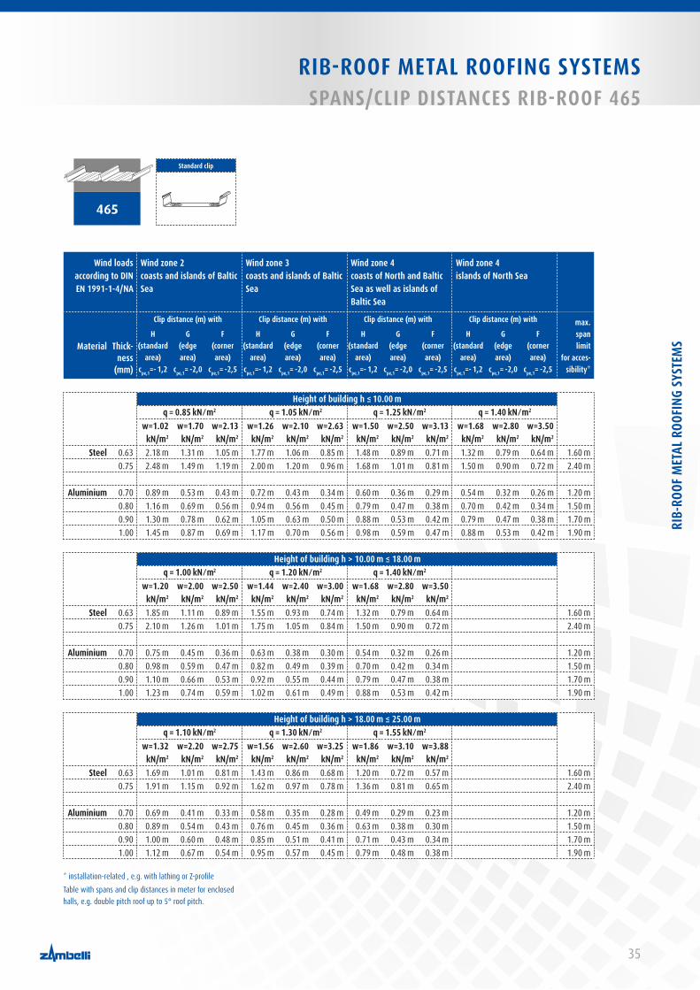
35
RIB-ROOF METAL ROOFING SYSTEMSSPANS/CLIP DISTANCES RIB-ROOF 465
465
Standard clip
Wind loads according to DIN EN 1991-1-4/NA
Wind zone 2coasts and islands of Baltic Sea
Wind zone 3coasts and islands of Baltic Sea
Wind zone 4coasts of North and Baltic Sea as well as islands of Baltic Sea
Wind zone 4islands of North Sea
Thick-ness
(mm)
Clip distance (m) with Clip distance (m) with Clip distance (m) with Clip distance (m) with max. span limit
for acces-sibility*
MaterialH
(standard area)
cpe,1=- 1,2
G (edge area)
cpe,1= -2,0
F (corner area)
cpe,1= -2,5
H (standard
area)cpe,1=- 1,2
G (edge area)
cpe,1= -2,0
F (corner area)
cpe,1= -2,5
H (standard
area)cpe,1=- 1,2
G (edge area)
cpe,1= -2,0
F (corner area)
cpe,1= -2,5
H (standard
area)cpe,1=- 1,2
G (edge area)
cpe,1= -2,0
F (corner area)
cpe,1= -2,5
Height of building h ≤ 10.00 m q = 0.85 kN ⁄ m2 q = 1.05 kN ⁄ m2 q = 1.25 kN ⁄ m2 q = 1.40 kN ⁄ m2
w=1.02 kN/m2
w=1.70 kN/m2
w=2.13 kN/m2
w=1.26 kN/m2
w=2.10 kN/m2
w=2.63 kN/m2
w=1.50 kN/m2
w=2.50 kN/m2
w=3.13 kN/m2
w=1.68 kN/m2
w=2.80kN/m2
w=3.50 kN/m2
Steel 0.63 2.18 m 1.31 m 1.05 m 1.77 m 1.06 m 0.85 m 1.48 m 0.89 m 0.71 m 1.32 m 0.79 m 0.64 m 1.60 m 0.75 2.48 m 1.49 m 1.19 m 2.00 m 1.20 m 0.96 m 1.68 m 1.01 m 0.81 m 1.50 m 0.90 m 0.72 m 2.40 m
Aluminium 0.70 0.89 m 0.53 m 0.43 m 0.72 m 0.43 m 0.34 m 0.60 m 0.36 m 0.29 m 0.54 m 0.32 m 0.26 m 1.20 m0.80 1.16 m 0.69 m 0.56 m 0.94 m 0.56 m 0.45 m 0.79 m 0.47 m 0.38 m 0.70 m 0.42 m 0.34 m 1.50 m0.90 1.30 m 0.78 m 0.62 m 1.05 m 0.63 m 0.50 m 0.88 m 0.53 m 0.42 m 0.79 m 0.47 m 0.38 m 1.70 m1.00 1.45 m 0.87 m 0.69 m 1.17 m 0.70 m 0.56 m 0.98 m 0.59 m 0.47 m 0.88 m 0.53 m 0.42 m 1.90 m
Height of building h > 10.00 m ≤ 18.00 mq = 1.00 kN ⁄ m2 q = 1.20 kN ⁄ m2 q = 1.40 kN ⁄ m2
w=1.20 kN/m2
w=2.00 kN/m2
w=2.50 kN/m2
w=1.44 kN/m2
w=2.40 kN/m2
w=3.00 kN/m2
w=1.68 kN/m2
w=2.80 kN/m2
w=3.50 kN/m2
Steel 0.63 1.85 m 1.11 m 0.89 m 1.55 m 0.93 m 0.74 m 1.32 m 0.79 m 0.64 m 1.60 m 0.75 2.10 m 1.26 m 1.01 m 1.75 m 1.05 m 0.84 m 1.50 m 0.90 m 0.72 m 2.40 m
Aluminium 0.70 0.75 m 0.45 m 0.36 m 0.63 m 0.38 m 0.30 m 0.54 m 0.32 m 0.26 m 1.20 m0.80 0.98 m 0.59 m 0.47 m 0.82 m 0.49 m 0.39 m 0.70 m 0.42 m 0.34 m 1.50 m0.90 1.10 m 0.66 m 0.53 m 0.92 m 0.55 m 0.44 m 0.79 m 0.47 m 0.38 m 1.70 m1.00 1.23 m 0.74 m 0.59 m 1.02 m 0.61 m 0.49 m 0.88 m 0.53 m 0.42 m 1.90 m
Height of building h > 18.00 m ≤ 25.00 mq = 1.10 kN ⁄ m2 q = 1.30 kN ⁄ m2 q = 1.55 kN ⁄ m2
w=1.32 kN/m2
w=2.20 kN/m2
w=2.75 kN/m2
w=1.56 kN/m2
w=2.60 kN/m2
w=3.25 kN/m2
w=1.86 kN/m2
w=3.10 kN/m2
w=3.88 kN/m2
Steel 0.63 1.69 m 1.01 m 0.81 m 1.43 m 0.86 m 0.68 m 1.20 m 0.72 m 0.57 m 1.60 m 0.75 1.91 m 1.15 m 0.92 m 1.62 m 0.97 m 0.78 m 1.36 m 0.81 m 0.65 m 2.40 m
Aluminium 0.70 0.69 m 0.41 m 0.33 m 0.58 m 0.35 m 0.28 m 0.49 m 0.29 m 0.23 m 1.20 m0.80 0.89 m 0.54 m 0.43 m 0.76 m 0.45 m 0.36 m 0.63 m 0.38 m 0.30 m 1.50 m0.90 1.00 m 0.60 m 0.48 m 0.85 m 0.51 m 0.41 m 0.71 m 0.43 m 0.34 m 1.70 m1.00 1.12 m 0.67 m 0.54 m 0.95 m 0.57 m 0.45 m 0.79 m 0.48 m 0.38 m 1.90 m
* installation-related , e.g. with lathing or Z-profileTable with spans and clip distances in meter for enclosed halls, e.g. double pitch roof up to 5° roof pitch.
RIB-
ROOF
MET
AL R
OOFI
NG S
YSTE
MS
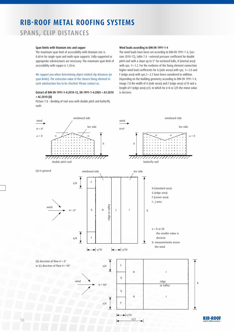
36
RIB-ROOF METAL ROOFING SYSTEMSSPANS, CLIP DISTANCES
windward side
lee side
h
butterfly roof
(a) in general
(b) direction of flow θ = 0° or (c) direction of flow θ = 90°
e = b or 2h the smaller value is decisive
b: measurements across the wind
H (standard area)G (edge area)F (corner area)I-, J-area
wind
θ=0°
a a a > 0
windward side
lee side
h
double pitch roof
wind
θ = 0°
a > 0 a a
windward side
e/4 F
F
G H
ridge
or v
alle
y
J I b
e/4
e/10 e/10
lee side
windθ = 0°
F
F
G
G
H I
IH
ridge or valley
e/4
e/4
e/10e/2
windθ = 90°
b
Span limits with titanium zinc and copperThe maximum span limit of accessibility with titanium zinc is 0.60 m for single-span and multi-span supports. Fully-supported or appropriate substructures are necessary. The maximum span limit of accessibility with copper is 1.20 m.
We support you when determining object-related clip distances (or span limits). The extraction value of the chosen fixing element in each substructure has to be checked. Please contact us.
Extract of DIN EN 1991-1-4:2010-12, EN 1991-1-4:2005 + A1:2010 + AC:2010 (D) Picture 7.8 – dividing of roof area with double pitch and butterfly roofs
Wind loads according to DIN EN 1991-1-4The wind loads have been set according to DIN EN 1991-1-4, (ver-sion 2010-12), table 7.4 – external pressure coefficient for double pitch roof with a slope up to 5° for enclosed halls, H (normal area) with cpe, 1=-1.2. For the evidence of the fixing element connection higher wind load coefficients for G (side areas) with cpe, 1=-2.0 and F (edge area) with cpe,1=-2.5 have been considered in addition.Depending on the building geometry according to DIN EN 1991-1-4, image 7.8 the width of G (side areas) and F (edge area) e/10 and a length of F (edge area) e/4, in which for e=b or 2/h the minor value is decisive.

37
1
2
2
3
3
4
RIB-ROOF METAL ROOFING SYSTEMS SPANS, CLIP DISTANCES
Wind zone νb,0 q
b,0
WZ 1 22.5 m/s 0.32 kN/m²WZ 2 25.0 m/s 0.39 kN/m²WZ 3 27.5 m/s 0.47 kN/m²WZ 4 30.0 m/s 0.56 kN/m²
The use of our directional clips and profiles RIB-ROOF Speed 500 is recommended in wind zones 3 and 4.
Contact us.
RIB-
ROOF
MET
AL R
OOFI
NG S
YSTE
MS
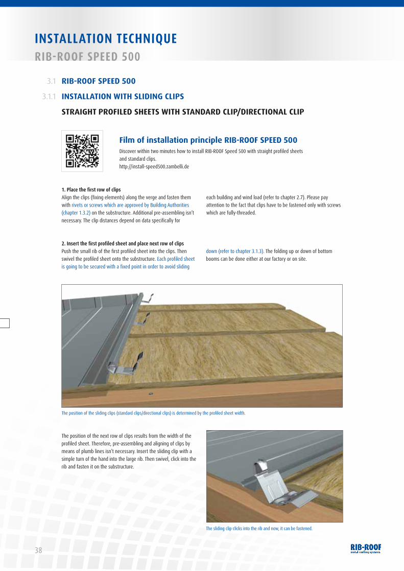
38
INSTALLATION TECHNIQUERIB-ROOF SPEED 500
RIB-ROOF SPEED 500
INSTALLATION WITH SLIDING CLIPS
STRAIGHT PROFILED SHEETS WITH STANDARD CLIP/DIRECTIONAL CLIP
3.1
3.1.1
1. Place the first row of clipsAlign the clips (fixing elements) along the verge and fasten them with rivets or screws which are approved by Building Author ities (chapter 1.3.2) on the substructure. Additional pre-assembling isn’t necessary. The clip distances depend on data specifically for
each building and wind load (refer to chapter 2.7). Please pay attention to the fact that clips have to be fastened only with screws which are fully-threaded.
2. Insert the first profiled sheet and place next row of clipsPush the small rib of the first profiled sheet into the clips. Then swivel the profiled sheet onto the substructure. Each profiled sheet is going to be secured with a fixed point in order to avoid sliding
down (refer to chapter 3.1.3). The folding up or down of bottom booms can be done either at our factory or on site.
The position of the next row of clips results from the width of the profiled sheet. Therefore, pre-assembling and aligning of clips by means of plumb lines isn’t necessary. Insert the sliding clip with a simple turn of the hand into the large rib. Then swivel, click into the rib and fasten it on the substructure.
Film of installation principle RIB-ROOF SPEED 500 Discover within two minutes how to install RIB-ROOF Speed 500 with straight profiled sheets and standard clips. http://install-speed500.zambelli.de
The position of the sliding clips (standard clips/directional clips) is determined by the profiled sheet width.
The sliding clip clicks into the rib and now, it can be fastened.
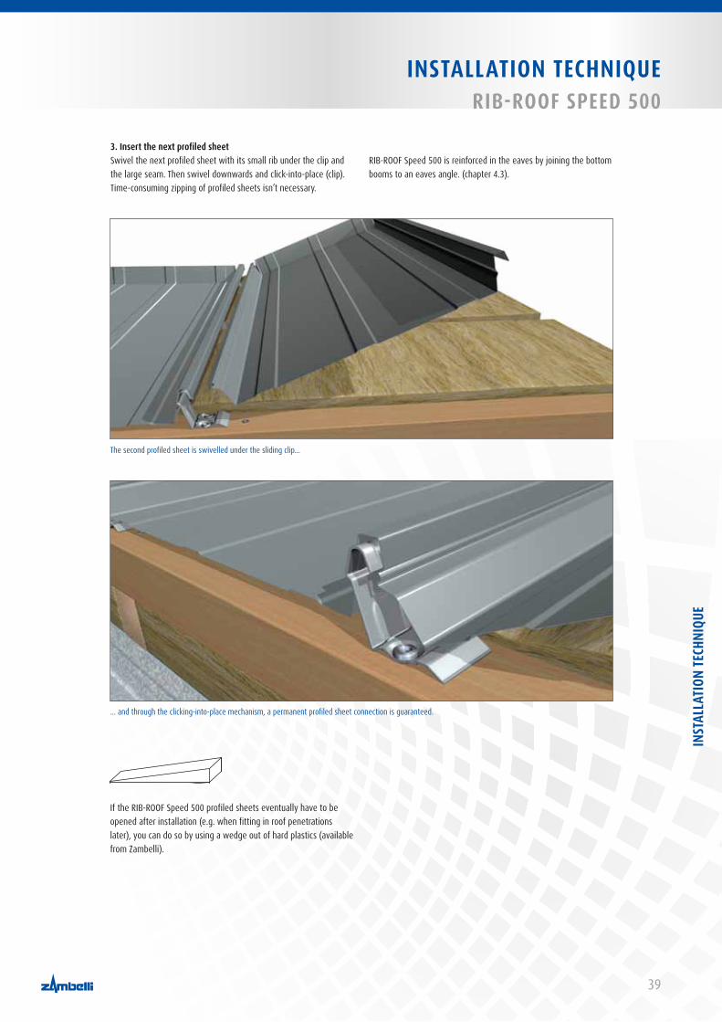
39
INSTALLATION TECHNIQUERIB-ROOF SPEED 500
3. Insert the next profiled sheetSwivel the next profiled sheet with its small rib under the clip and the large seam. Then swivel downwards and click-into-place (clip). Time-consuming zipping of profiled sheets isn’t necessary.
RIB-ROOF Speed 500 is reinforced in the eaves by joining the bottom booms to an eaves angle. (chapter 4.3).
The second profiled sheet is swivelled under the sliding clip...
... and through the clicking-into-place mechanism, a permanent profiled sheet connection is guaranteed.
If the RIB-ROOF Speed 500 profiled sheets eventually have to be opened after installation (e.g. when fitting in roof penetrations later), you can do so by using a wedge out of hard plastics (available from Zambelli).
INST
ALLA
TION
TECH
NIQU
E
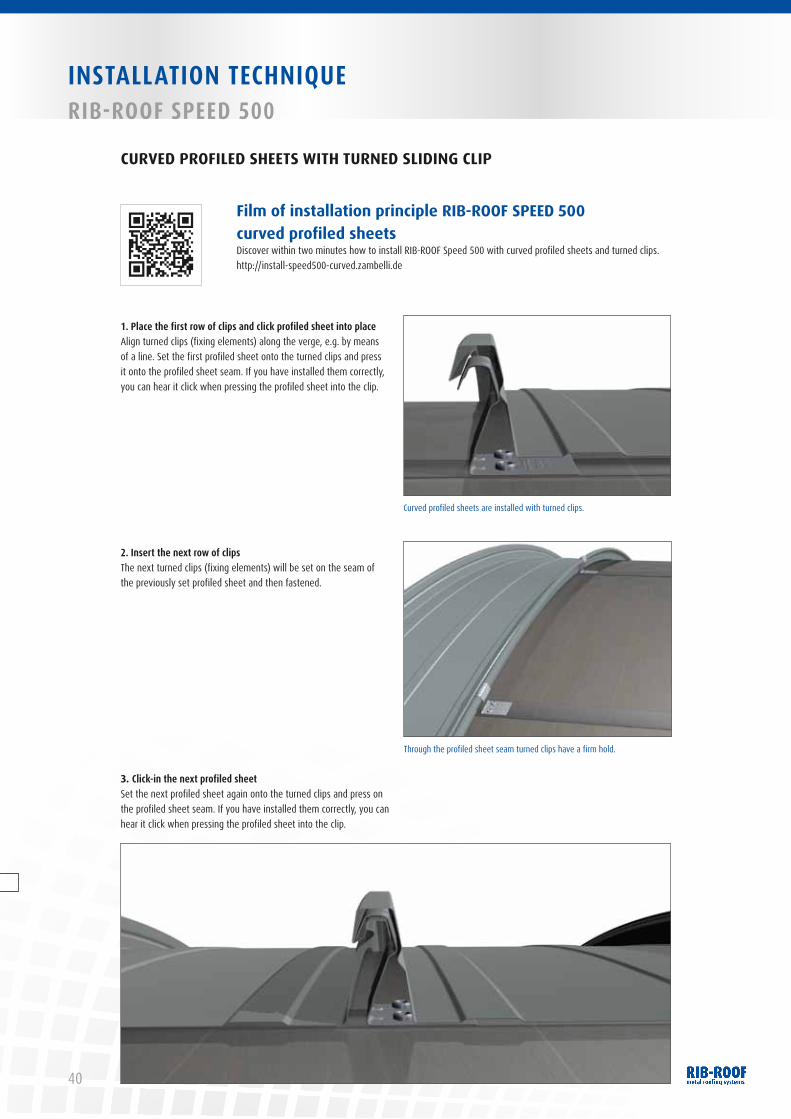
40
INSTALLATION TECHNIQUERIB-ROOF SPEED 500
1. Place the first row of clips and click profiled sheet into placeAlign turned clips (fixing elements) along the verge, e.g. by means of a line. Set the first profiled sheet onto the turned clips and press it onto the profiled sheet seam. If you have installed them correctly, you can hear it click when pressing the profiled sheet into the clip.
2. Insert the next row of clipsThe next turned clips (fixing elements) will be set on the seam of the previously set profiled sheet and then fastened.
3. Click-in the next profiled sheetSet the next profiled sheet again onto the turned clips and press on the profiled sheet seam. If you have installed them correctly, you can hear it click when pressing the profiled sheet into the clip.
Film of installation principle RIB-ROOF SPEED 500 curved profiled sheets Discover within two minutes how to install RIB-ROOF Speed 500 with curved profiled sheets and turned clips. http://install-speed500-curved.zambelli.de
CURVED PROFILED SHEETS WITH TURNED SLIDING CLIP
Curved profiled sheets are installed with turned clips.
Through the profiled sheet seam turned clips have a firm hold.
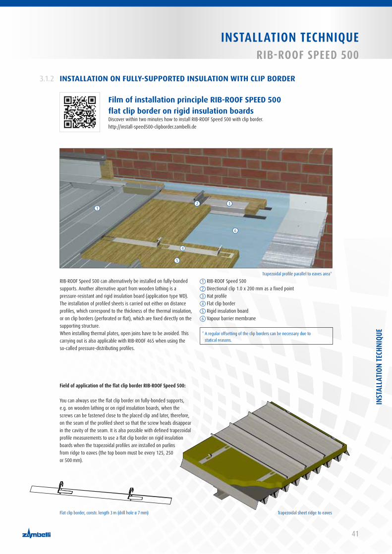
41
INSTALLATION TECHNIQUERIB-ROOF SPEED 500
Film of installation principle RIB-ROOF SPEED 500 flat clip border on rigid insulation boards Discover within two minutes how to install RIB-ROOF Speed 500 with clip border. http://install-speed500-clipborder.zambelli.de
INSTALLATION ON FULLY-SUPPORTED INSULATION WITH CLIP BORDER3.1.2
Field of application of the flat clip border RIB-ROOF Speed 500:
You can always use the flat clip border on fully-bonded supports, e.g. on wooden lathing or on rigid insulation boards, when the screws can be fastened close to the placed clip and later, therefore, on the seam of the profiled sheet so that the screw heads disappear in the cavity of the seam. It is also possible with defined trapezoidal profile meas urements to use a flat clip border on rigid insulation boards when the trapezoidal profiles are installed on purlins from ridge to eaves (the top boom must be every 125, 250 or 500 mm).
Flat clip border, constr. length 3 m (drill hole ø 7 mm) Trapezoidal sheet ridge to eaves
Trapezoidal profile parallel to eaves area*RIB-ROOF Speed 500 can alternatively be installed on fully-bonded supports. Another alternative apart from wooden lathing is a pressure-resistant and rigid insulation board (application type WD). The installation of profiled sheets is carried out either on distance profiles, which correspond to the thickness of the thermal insulation, or on clip borders (perforated or flat), which are fixed directly on the supporting structure. When installing thermal plates, open joins have to be avoided. This carrying out is also applicable with RIB-ROOF 465 when using the so-called pressure-distributing profiles.
* A regular offsetting of the clip borders can be necessary due to statical reasons.
1 RIB-ROOF Speed 5002 Directional clip 1.0 x 200 mm as a fixed point3 Hat profile4 Flat clip border5 Rigid insulation board6 Vapour barrier membrane
12 3
4
5
6
INST
ALLA
TION
TECH
NIQU
E
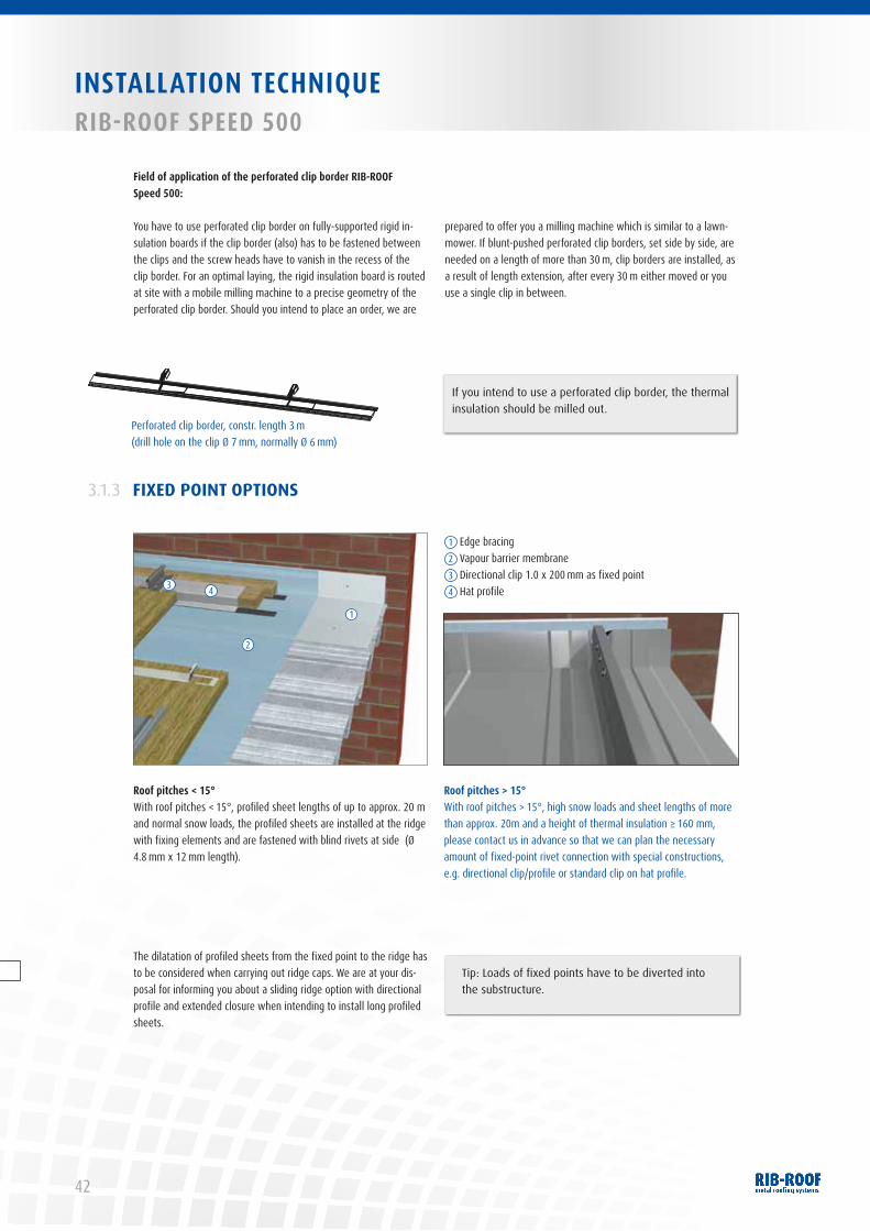
42
INSTALLATION TECHNIQUERIB-ROOF SPEED 500
Field of application of the perforated clip border RIB-ROOF Speed 500:
You have to use perforated clip border on fully-supported rigid in-sulation boards if the clip border (also) has to be fastened between the clips and the screw heads have to vanish in the recess of the clip border. For an optimal laying, the rigid insulation board is routed at site with a mobile milling machine to a precise geometry of the perforated clip border. Should you intend to place an order, we are
prepared to offer you a milling machine which is similar to a lawn-mower. If blunt-pushed perforated clip borders, set side by side, are needed on a length of more than 30 m, clip borders are installed, as a result of length extension, after every 30 m either moved or you use a single clip in between.
Perforated clip border, constr. length 3 m (drill hole on the clip Ø 7 mm, normally Ø 6 mm)
If you intend to use a perforated clip border, the thermal insulation should be milled out.
Roof pitches < 15°With roof pitches < 15°, profiled sheet lengths of up to approx. 20 m and normal snow loads, the profiled sheets are installed at the ridge with fixing elements and are fastened with blind rivets at side (Ø 4.8 mm x 12 mm length).
The dilatation of profiled sheets from the fixed point to the ridge has to be considered when carrying out ridge caps. We are at your dis-posal for informing you about a sliding ridge option with directional profile and extended closure when intending to install long profiled sheets.
Roof pitches > 15°With roof pitches > 15°, high snow loads and sheet lengths of more than approx. 20m and a height of thermal insulation ≥ 160 mm, please contact us in advance so that we can plan the necessary amount of fixed-point rivet connection with special constructions, e.g. directional clip/profile or standard clip on hat profile.
FIXED POINT OPTIONS3.1.3
1 Edge bracing2 Vapour barrier membrane3 Directional clip 1.0 x 200 mm as fixed point4 Hat profile
1
2
3 4
Tip: Loads of fixed points have to be diverted into the substructure.
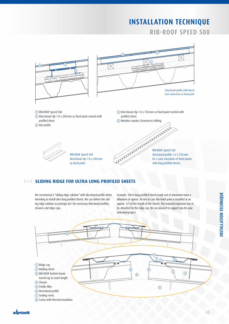
43
INSTALLATION TECHNIQUERIB-ROOF SPEED 500
1 RIB-ROOF Speed 5002 Directional clip 1.0 x 200 mm as fixed point riveted with
profiled sheet3 Hat profile
4 Directional clip 1.0 x 750 mm as fixed point riveted with profiled sheet
5 Wooden counter-/transverse lathing
1
1
2
4
3
5
SLIDING RIDGE FOR ULTRA LONG PROFILED SHEETS3.1.4
We recommend a “sliding ridge solution” with directional profile when intending to install ultra long profiled sheets. We can deliver the slid-ing ridge solution as package incl. the necessary directional profiles, closures and ridge caps.
Example: 100 m long profiled sheets made out of aluminium have a dilatation of approx. 40 mm in case the fixed point is installed at an approx. 1/3 of the length of the sheets. The material expansion has to be absorbed by the ridge cap. We are pleased to support you for your individual project.
RIB-ROOF Speed 500 directional profile 1.0 x 750 mm for a save execution of fixed points with long profiled sheets
RIB-ROOF Speed 500 directional clip 1.0 x 200 mm as fixed point
1 Ridge cap2 Holding sheet3 RIB-ROOF bottom boom
turned-up at seam height4 Closure5 Profile filler6 Directional profile7 Sealing rivets8 Cavity with thermal insulation
6
Directional profile with lateral rivet connection as fixed point
6
2
3
4
5
7
8
9
1
66
INST
ALLA
TION
TECH
NIQU
E

44
INSTALLATION TECHNIQUERIB-ROOF 465
RIB-ROOF 465
INSTALLATION WITH SLIDING CLIPS
STRAIGHT PROFILED SHEETS WITH STANDARD CLIPS
3.2
1. Place the first row of clipsAlign the clips (start or standard clips) along the verge and fasten them with rivets and screws approved by Construction Authorities (chapter 1.3.2). Further pre-assembling of sliding clips isn’t necessary. The sliding clip distances depend on project specific data (span limits/fixing element distances for enclosed halls, refer to chapter 2.8). Please generally pay attention to a higher wind load in edge and corner areas
2. Insert the first profiled sheetThe first profiled sheet is swivelled with the large rib into the overlapping start clip and clicked onto the clip in the middle rib. Alternatively with standard clip, it is possible to press the large rib in the overlapping area together and click the profiled sheet with large
and middle rib onto the clip (click-into-place is hearable ). Fasten the profiled sheet with brackets which spread to the outer rib on the substructure (this isn’t necessary when using the start clip).
Film of installation principle RIB-ROOF 465 Discover within two minutes how to install RIB-ROOF 465 with straight profiled sheets and standard clips. http://install-465.zambelli.de
The first row of sliding clips with start clips is aligned along the verge side.

45
INSTALLATION TECHNIQUERIB-ROOF 465
3. Place the next row of clipsThe position of the next row depends on the construction width of the elements. We recommend to use a plumb line on the eaves as well as to regularly check the construction width in order to ensure a parallel and aligned installation of the profiled sheets.Now fasten the next row of clips at an angle of > 90° to the faste-ning structure to the rear edging of the bare small rib of the profiled sheet and swivel the profiled sheet onto the substructure. Click the clips into place in the longitudinal trough of the rib and fasten them onto the substructure.
4. Insert the next profiled sheetClick the large and middle rib of the second profiled sheet onto the first one and onto the exposed part of the clip. Use the alternate merging principle and proceed from eaves point to ridge point. The clicking normally occurs by well-aimed walking (utilities: wooden
batten with drilled grooves). Thanks to moulded longitudinal troughs, the longitudinal pushes are rainproof after having been clicked into place. Zipping by machine or working concerning crafts-manship isn’t necessary.
Please fasten every profiled sheet with a fixed point clip or fixed-point profile in order to avoid a slide-off. With roof pitches < 15°, sheet lengths of up to 20 m and normal snow loads, the small rib of every sheet is fastened with a blind rivet (Ø 4.8 mm x 12 mm length) in the ridge to the fixing element. The rivet head is going to be covered with the large rib of the next profiled sheet.Set the fixed point with sufficient distance to the ridge when installing longer profiled sheets in order to ensure a greater material expansion. Please also take into consideration the length expansion of the profiled sheet from fixed-point to ridge, also when using ridge caps, e.g. with enlarged closures. With roof pitches > 15°, high snow loads and sheet lengths of more than approx. 20 m and height of thermal insulation ≥ 160 mm , please contact us in advance so that we can plan the necessary amount of fixed-points with special constructions, e.g. fixed-point clip/fixed-point profile or standard clips on hat profile.
Fixed-point clip
The construction widths should be checked when laying profiled sheets. The standard clip is
used up from the second row of clips.
INST
ALLA
TION
TECH
NIQU
E
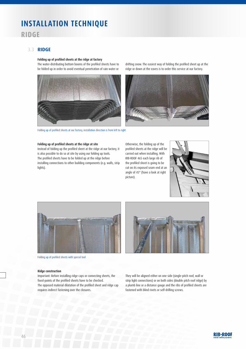
46
INSTALLATION TECHNIQUERIDGE
RIDGE3.3
Folding up of profiled sheets at the ridge at factoryThe water-distributing bottom booms of the profiled sheets have to be folded up in order to avoid eventual penetration of rain water or
drifting snow. The easiest way of folding the profiled sheet up at the ridge or down at the eaves is to order this service at our factory.
Folding up of profiled sheets at the ridge at siteInstead of folding up the profiled sheet at the ridge at our factory, it is also possible to do so at site by using our folding up tools.The profiled sheets have to be folded up at the ridge before installing connections to other building components (e.g. walls, strip lights).
Otherwise, the folding up of the profiled sheets at the ridge will be carried out when installing. With RIB-ROOF 465 each large rib of the profiled sheet is going to be cut on its exposed seam end at an angle of 45° (have a look at right picture).
Ridge constructionImportant: Before installing ridge caps or connecting sheets, the fixed-points of the profiled sheets have to be checked. The opposed material dilatation of the profiled sheet and ridge cap requires indirect fastening over the closures.
They will be aligned either on one side (single-pitch roof, wall or strip light connections) or on both sides (double pitch roof ridge) by a plumb line or a distance gauge and the ribs of profiled sheets are fastened with blind rivets or self-drilling screws.
Folding up of profiled sheets at our factory, installation direction is from left to right
Folding up of profiled sheets with special tool
47
INSTALLATION TECHNIQUETRANSvERSAL JOINT, NOTE
IMPORTANT BASIC RULES FOR INSTALLATION3.6
1. The installation has to be stopped with extreme weather conditions, single profiled sheets have to be fixed immediately. Installation can also be carried out with low outside temperatures since zipping isn’t necessary with RIB-ROOF.
2. If you intend to walk on profiled sheets during installation, please refer to tables in chapter 2.5 and 3.4 (installation-related maximum support span of accessibility).
3. Before walking on the roof please point out to other craftsmen that they have to put down load-spreading elements in their walkway area, in order to avoid deformation or damage of profiled sheets. But be aware: before the customer has taken over the roof every damage may have to be paid by the company which has installed the profiled sheets provided that there isn’t another person responsible.
4. The connection of the profiled sheets to above-ground building components requires folding up of bottom boom before installa-tion (available at our factory), have a look at chapter 3.3.
SEALING OF THE LONGIDUTIONAL JOINT3.5
TRANSVERSAL JOINT3.4
Profiled sheet transversal joints are generally not necessary since the length of the material dilatation is taken up by the fixing elements (clips). If the profiled sheets are too long (> 33 m) and, therefore, can not be transported with a truck, rollforming at site can be offered (refer to chapter 1.4.1).
However, if transversal joints are necessary, preferably welded profiled sheets out of aluminium are chosen. In certain cases and exclusively with roof pitches of more than 7°, transversal joints with sealing rivets and sealing material are executed. Contact us!
With roof pitches of less than 1.5° in subareas and differences in measurements or unevenness in the substructure (danger of forming puddle), an additional measure of sealing is recommended, the inserting of sealing tapes (e.g. brand ISO Chemie).
This solution is also recommended with curved roof constructions in the highest point running continuously up to reaching the angle of inclination of 1.5°.
INSPECTION AND MAINTENANCE3.7
If you want more information about a maintenance contract or roof and façade controls, please visit the Central Association for Sanitary, Heating and Air Conditioning (ZVSHK) at www.wasserwaermeluft.de or the IFBS (“Industrieverband für
Bausysteme im Metallleichtbau”), which is an important industrial association that represents companies operating in the field of construction systems in light metal, at www.ifbs.de.
INST
ALLA
TION
TECH
NIQU
E

48
1 Ridge cap2 Closure3 Profile filler - top side
4 RIB-ROOF Speed 5005 Standard clip Speed 5006 Profile filler - rear side
7 Eaves angle8 Gutter inlet sheet
1
2
3
4
6
5
7
8
RIB-ROOF Speed 500
CONSTRUCTION DETAILSOvERvIEW
The development of details of ridges, verges and eaves always has to be homogeneous in the interest of architecture (eventually instal-lation of samples in accordance with the client). In the following you will get some suggestions as an example for construction details.
The standard CAD detail drawings in all common file formats can be downloaded from our website www.zambelli.com – or simply ask for our CD.

49
CONSTRUCTION DETAILS OvERvIEW
1 Ridge cap2 Closure3 Profile filler - top side
4 RIB-ROOF 4655 Standard clip 4656 Profile filler - rear side
7 Eaves angle8 Gutter inlet sheet
1
2
3
4
6 5
7
8
RIB-ROOF 465
CONS
TRUC
TION
DET
AILS

50
CONSTRUCTION DETAILSRIDGE
RIDGE
DOUBLE PITCH RIDGE
4.1
4.1.1
The double pitch ridge without any openings for ventilation (for single-skinned roof constructions, warm roof) is hung on the closu-res with its backward-bending on both sides (crimping with approx. 10 mm radius) and pressed together on its seam. The connection
is folded by craftsmen or is carried out with blind rivets on the extension gadgets.If required fillers will be installed. The structure and distance of extension gadgets have to be observed in any case.
1 Double pitch ridge cap2 Closure
3 Profile filler - top side4 Thermal insulation
1
2
3
4

51
CONSTRUCTION DETAILS RIDGE
The double pitch ridge with an opening for ventilation (for double-skinned roof constructions, cold roof) is a standard product of our delivery program and available in all materials according to our roo-
fing materials as a construction kit with two integrated ventilation closures and profile fillers.
SINGLE PITCH RIDGE4.1.2
The single pitch ridge (without / with openings for ventilation) is similar to the verge, mentioned in chapter 4.5, and forms a creative unit also with regard to installation and assembly. In order to avoid deformations of the ridge cap, it can be underlain with a galvanised steel profile with a thickness of at least 1.00 mm.
Ridge and arris cap ventilated
1 Ridge / arris cap2 RIB-ROOF, optionally at rear side
with fleece coating for anti-con-densationv / sound absorption
3 Ventilation closure4 Profile filler for ridge / arris5 Supporting structure at site
(e.g. wooden purlins)
1
23
4 4
5
1 Single pitch ridge cap2 Closure3 Profile filler - top side4 RIB-ROOF5 Wooden counter / transverse lathing
with thermal insulation6 Vapour barrier membrane
1
2
3
4
5
6
CONS
TRUC
TION
DET
AILS
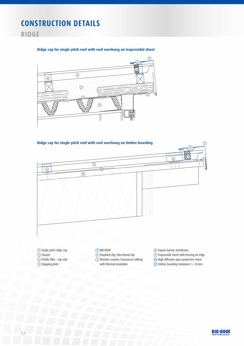
52
CONSTRUCTION DETAILSRIDGE
Ridge cap for single pitch roof with roof overhang on trapezoidal sheet
Ridge cap for single pitch roof with roof overhang on timber boarding
1 Single pitch ridge cap2 Closure3 Profile filler - top side4 Stopping plate
5 RIB-ROOF6 Standard clip / directional clip7 Wooden counter / transverse lathing
with thermal insulation
8 Vapour barrier membrane9 Trapezoidal sheet with bracing on edge10 High diffusion-open protective sheet11 Timber boarding minimum t = 24 mm
12
3
4
56
7
8
9
6
5
1011
21
36 4

53
CONSTRUCTION DETAILSARRIS
ARRIS4.2
Arris are finished in a similar way as a double pitch ridge. The clo-sures aren’t equipped at our factory with notches for profiled sheet ribs (
s
high seams). These will be marked at site and cut with plate
shears in order to reach an optimal fitting. The construction details of ridge caps can be used in the general sense.
Analogous to a ventilation ridge cap, there can also be used a ven-tilated cover sheet for arris utilizing a ventilation closure (delivery without notches).
1 RIB-ROOF2 Rigid insulation boards
3 Clip border4 Vapour barrier membrane
5 Cover sheet for arris6 Suspended profile for arris
1
2
3
4
5
6
CONS
TRUC
TION
DET
AILS
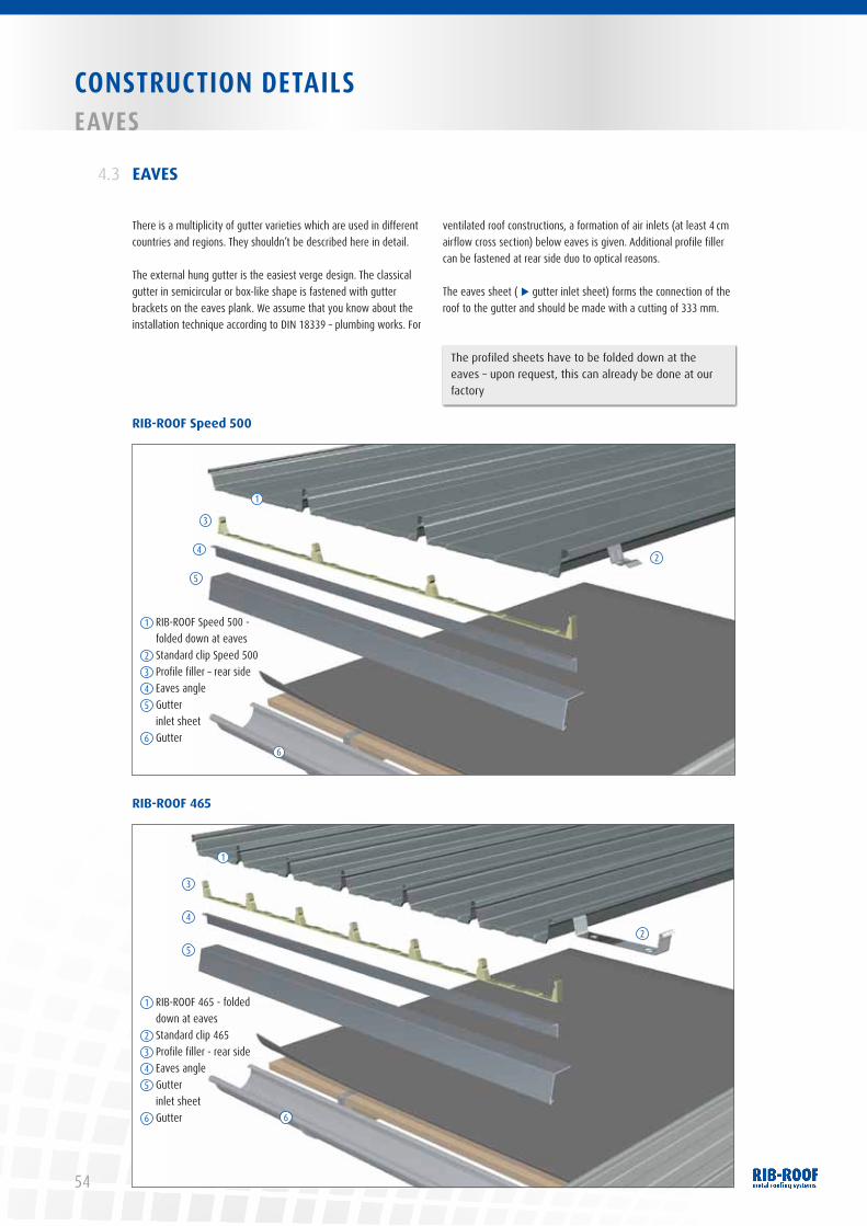
54
CONSTRUCTION DETAILSEAvES
EAVES4.3
There is a multiplicity of gutter varieties which are used in different countries and regions. They shouldn’t be described here in detail.
The external hung gutter is the easiest verge design. The classical gutter in semicircular or box-like shape is fastened with gutter brackets on the eaves plank. We assume that you know about the installation technique according to DIN 18339 – plumbing works. For
ventilated roof constructions, a formation of air inlets (at least 4 cm airflow cross section) below eaves is given. Additional profile filler can be fastened at rear side duo to optical reasons.
The eaves sheet (
s
gutter inlet sheet) forms the connection of the roof to the gutter and should be made with a cutting of 333 mm.
The profiled sheets have to be folded down at the eaves – upon request, this can already be done at our factory
RIB-ROOF 465
RIB-ROOF Speed 500
1 RIB-ROOF Speed 500 - folded down at eaves
2 Standard clip Speed 5003 Profile filler – rear side4 Eaves angle5 Gutter
inlet sheet6 Gutter
1
3
24
5
6
1 RIB-ROOF 465 - folded down at eaves
2 Standard clip 4653 Profile filler - rear side4 Eaves angle5 Gutter
inlet sheet6 Gutter 6
5
4
3
2
1

55
CONSTRUCTION DETAILS EAvES
The high diffusion-open protective sheet or other separation layers cover the eaves sheet in order to divert eventually arising secondary water which accumulates itself in the gutter. The gutter overhang of the profiled sheets depends on the drawings in chapter 4.3 (at least 30 mm). After installing the profiled sheets, water-loaded bottom booms have to be feather-edged with tools for folding up and down profiled sheets to the gutter.
Detail box gutter with snow guard and ice stopping system
The eaves angle isn’t technically necessary with RIB-ROOF 465.
Securing of eaves against wind load with RIB-ROOF 465
Eaves formations with sloped steps are used as a creative element in architecture or with extreme long profiled sheets. The detailed construction single ridge roof applies, in the general sense, to the rising wall.
The securing of eaves against higher wind load on eaves is carried out when there is an overlapping seam with rivets.
Please refer to chapter 4.4 “Sloped steps”.
1 Box gutter2 Gutter inlet sheet3 Eaves angle, optionally with profile
fillers at rear side
4 High diffusion-open protective sheet5 Snow guard bracket6 Snow guard pipe Ø 32 mm7 Ice stopper
8 RIB-ROOF – folded down at eaves9 Timber boarding10 Rafter11 Standard clip / directional clip
1
2
3
8
4
5
6
7
9
10
11
2
1
34 5
8
6
9
Eaves construction with roof overhang
7
1 Halfround gutter2 Gutter inlet sheet3 Eaves angle, optionally with profile fillers
at rear side4 Timber boarding5 Thermal insulation6 Eaves rafter7 RIB-ROOF – folded down at eaves8 Standard clip / directional clip9 High diffusion-open protective sheet
Alternatively, a roof overhang with an overhanging direc tional profile can be realized with RIB-ROOF Speed 500.
CONS
TRUC
TION
DET
AILS
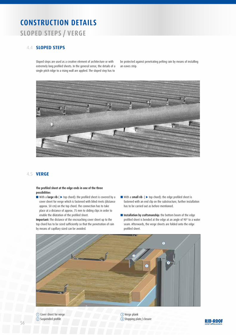
56
CONSTRUCTION DETAILSSLOPED STEPS / vERGE
SLOPED STEPS4.4
Sloped steps are used as a creative element of architecture or with extremely long profiled sheets. In the general sense, the details of a single pitch ridge to a rising wall are applied. The sloped step has to
be protected against penetrating pelting rain by means of installing an eaves strip.
VERGE4.5
The profiled sheet at the edge ends in one of the three possibilities■ With a large rib (
s
top chord): the profiled sheet is covered by a cover sheet for verge which is fastened with blind rivets (distance approx. 50 cm) on the top chord. The connection has to take place at a distance of approx. 75 mm to sliding clips in order to enable the dilatation of the profiled sheet.
Important: The distance of the encroaching cover sheet up to the top chord has to be sized sufficiently so that the penetration of rain by means of capillary sized can be avoided.
■ With a small rib (
s
top chord): the edge profiled sheet is fastened with an end clip on the substructure, further installation has to be carried out as before-mentioned.
■ Installation by craftsmanship: the bottom boom of the edge profiled sheet is bended at the edge at an angle of 90° to a water seam. Afterwards, the verge sheets are folded onto the edge profiled sheet.
1 Cover sheet for verge2 Suspended profile
3 Verge plank4 Stopping plate / closure
1
2
34
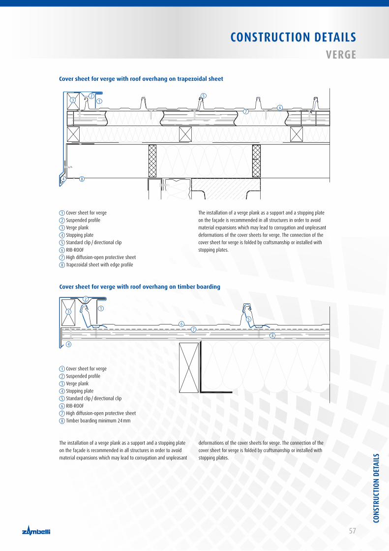
57
CONSTRUCTION DETAILS vERGE
Cover sheet for verge with roof overhang on trapezoidal sheet
Cover sheet for verge with roof overhang on timber boarding
The installation of a verge plank as a support and a stopping plate on the façade is recommended in all structures in order to avoid material expansions which may lead to corrugation and unpleasant deformations of the cover sheets for verge. The connection of the cover sheet for verge is folded by craftsmanship or installed with stopping plates.
12
1 Cover sheet for verge2 Suspended profile3 Verge plank4 Stopping plate5 Standard clip / directional clip6 RIB-ROOF7 High diffusion-open protective sheet8 Trapezoidal sheet with edge profile
7
35
6
4 8
The installation of a verge plank as a support and a stopping plate on the façade is recommended in all structures in order to avoid material expansions which may lead to corrugation and unpleasant
deformations of the cover sheets for verge. The connection of the cover sheet for verge is folded by craftsmanship or installed with stopping plates.
1
2
3
4
56
78
1 Cover sheet for verge2 Suspended profile3 Verge plank4 Stopping plate5 Standard clip / directional clip6 RIB-ROOF7 High diffusion-open protective sheet8 Timber boarding minimum 24 mm
CONS
TRUC
TION
DET
AILS
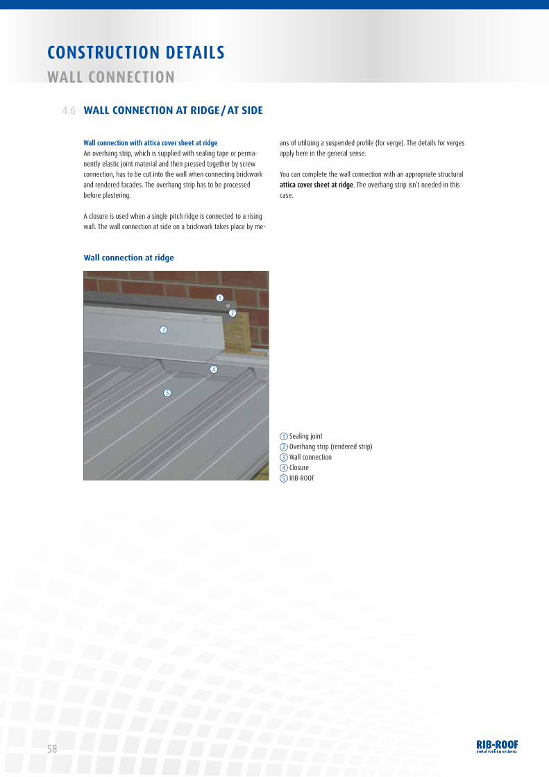
58
CONSTRUCTION DETAILSWALL CONNECTION
WALL CONNECTION AT RIDGE / AT SIDE4.6
Wall connection with attica cover sheet at ridgeAn overhang strip, which is supplied with sealing tape or perma-nently elastic joint material and then pressed together by screw connection, has to be cut into the wall when connecting brickwork and rendered facades. The overhang strip has to be processed before plastering.
A closure is used when a single pitch ridge is connected to a rising wall. The wall connection at side on a brickwork takes place by me-
ans of utilizing a suspended profile (for verge). The details for verges apply here in the general sense.
You can complete the wall connection with an appropriate structural attica cover sheet at ridge. The overhang strip isn’t needed in this case.
Wall connection at ridge
1 Sealing joint2 Overhang strip (rendered strip)3 Wall connection4 Closure5 RIB-ROOF
1
2
3
4
5

59
CONSTRUCTION DETAILS WALL CONNECTION
The wall connection at side is installed on metal, brickwork and other façade constructions either parallel or tapered to the profiled sheets.
The construction details for verges apply here in the general sense. The overhang strip (rendered strip), as mentioned in section 4.1.2 (single pitch ridge on a rising wall), is to be used when exposed concrete, brickwork or plastered walls have to be connected to it. With roof pitches of less than 25°, the connection height of 15 cm shouldn’t be below them.
The connection on an attica at side requires a detailed connection in two parts. Therefore, the connection to the profiled sheets has to be carried out as mentioned above. The flashing of a tapered sheet has to be folded into the bending at edge of the connection at side by craftsmanship.
Wall connection at side on brickwork or plastered façade
1 Sealing joint2 Overhang strip (rendered strip)3 Wall connection at side4 Suspended profile
5 RIB-ROOF6 Standard clip / directional clip7 High diffusion-open protective sheet (optional)8 Vapour barrier membrane
1
2
34
5
6
7
8
CONS
TRUC
TION
DET
AILS

60
CONSTRUCTION DETAILSINTERNAL GUTTER
INTERNAL GUTTER
Internal gutters are special constructions. Therefore, we recommend to absolutely follow the following safety measures:
4.7
■ The sizing of the gutter and downpipe (where applicable emer-gency overflow) has to be carried out according to DIN 18460 or DIN 1986-100 and enables a professional installation and cleaning. The amount of outlets (at least 2) has to be doubled from the arithmetical result.
■ The length expansions have to be guaranteed with an appropria-te amount of extension elements.
■ The outlets have to be made funnel-shaped and connected to the supporting and water-loaded gutters. According to DIN 1986-100, the run-off capacity has to be reduced arithmetically by 50% when using gutter sieves.
■ The installation of the gutter has to be adapted in connection with thermal-insulated roof constructions (use rigid insulation boards).
■ The minimum distance between supporting and water-loaded gutter should be at least 20 mm.
■ A gutter slope of at least 5 mm/n should be guaranteed.■ The gutter has to be kept clear from snow by installing a snow
guard system and thermostatically controlled gutter heating.■ Conclude a maintenance agreement with the client.■ Moreover, the standards for plumbing works have to be adhered,
published by the Central Association for Sanitary, Heating and Air Conditioning, St. Augustin.
Internal gutter with safety gutter
1 Water-loaded gutter2 Safety gutter3 Gutter inlet sheet4 Standard clip / directional clip5 Wooden plank6 RIB-ROOF7 Gutter heating (optional)8 Rigid insulation board9 Outlet in two parts,
welded with tapered inlet
1
2
3 4
5
6
7 7
8 9
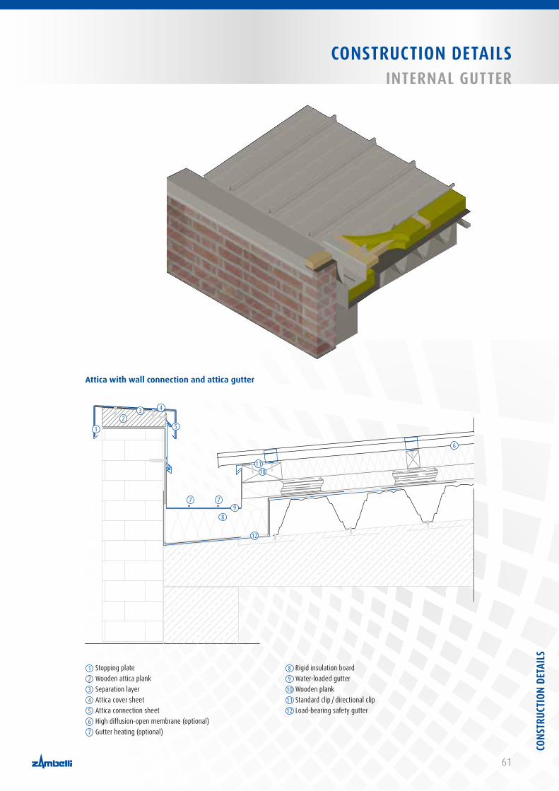
61
CONSTRUCTION DETAILSINTERNAL GUTTER
1 Stopping plate2 Wooden attica plank3 Separation layer4 Attica cover sheet5 Attica connection sheet6 High diffusion-open membrane (optional)7 Gutter heating (optional)
8 Rigid insulation board9 Water-loaded gutter10 Wooden plank11 Standard clip / directional clip12 Load-bearing safety gutter
Attica with wall connection and attica gutter
12
3 4
5
6
7 7
89
1011
12CO
NSTR
UCTI
ON D
ETAI
LS
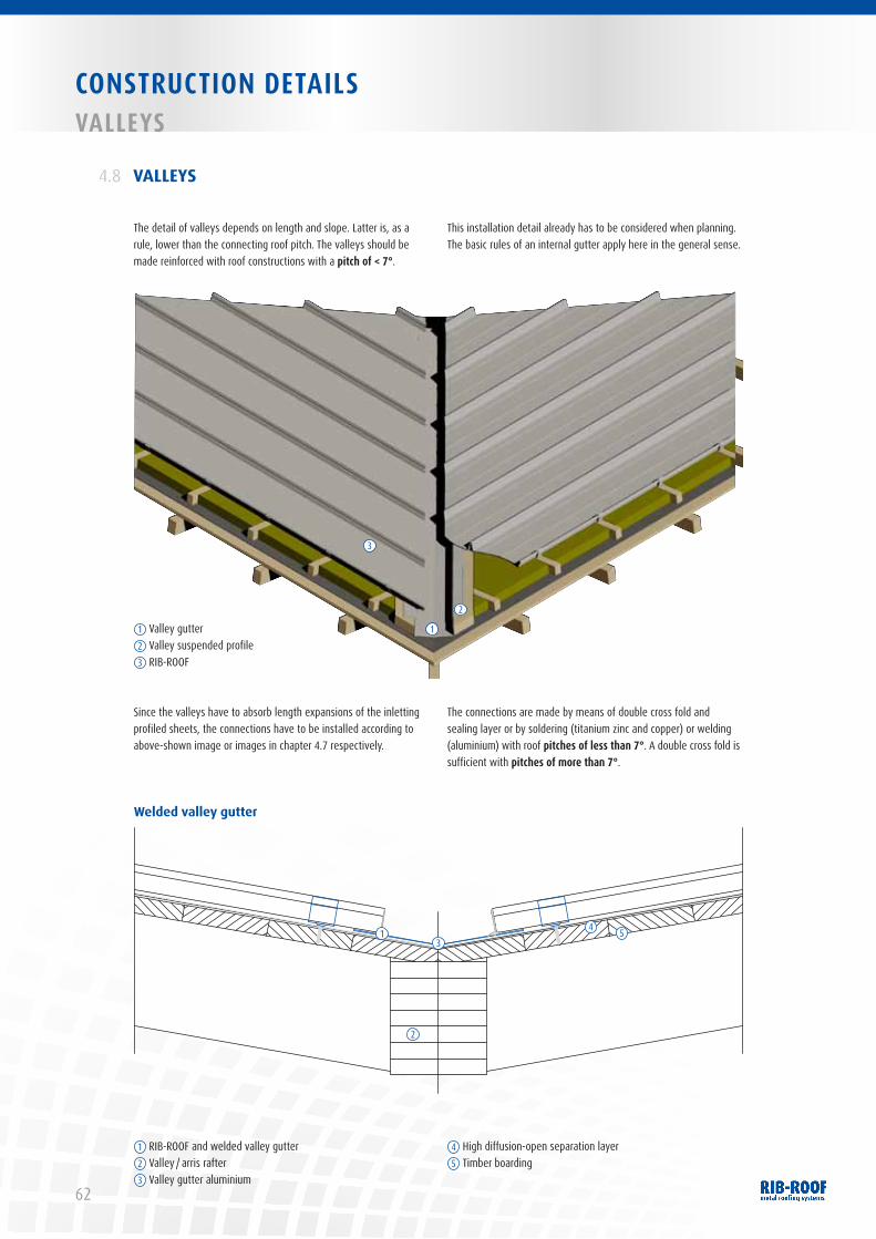
62
CONSTRUCTION DETAILSvALLEYS
VALLEYS
The detail of valleys depends on length and slope. Latter is, as a rule, lower than the connecting roof pitch. The valleys should be made reinforced with roof constructions with a pitch of < 7°.
This installation detail already has to be considered when planning. The basic rules of an internal gutter apply here in the general sense.
4.8
Since the valleys have to absorb length expansions of the inletting profiled sheets, the connections have to be installed according to above-shown image or images in chapter 4.7 respectively.
The connections are made by means of double cross fold and sealing layer or by soldering (titanium zinc and copper) or welding (aluminium) with roof pitches of less than 7°. A double cross fold is sufficient with pitches of more than 7°.
Welded valley gutter
1 Valley gutter2 Valley suspended profile3 RIB-ROOF
1
2
3
1 RIB-ROOF and welded valley gutter2 Valley / arris rafter3 Valley gutter aluminium
4 High diffusion-open separation layer5 Timber boarding
1
2
34 5
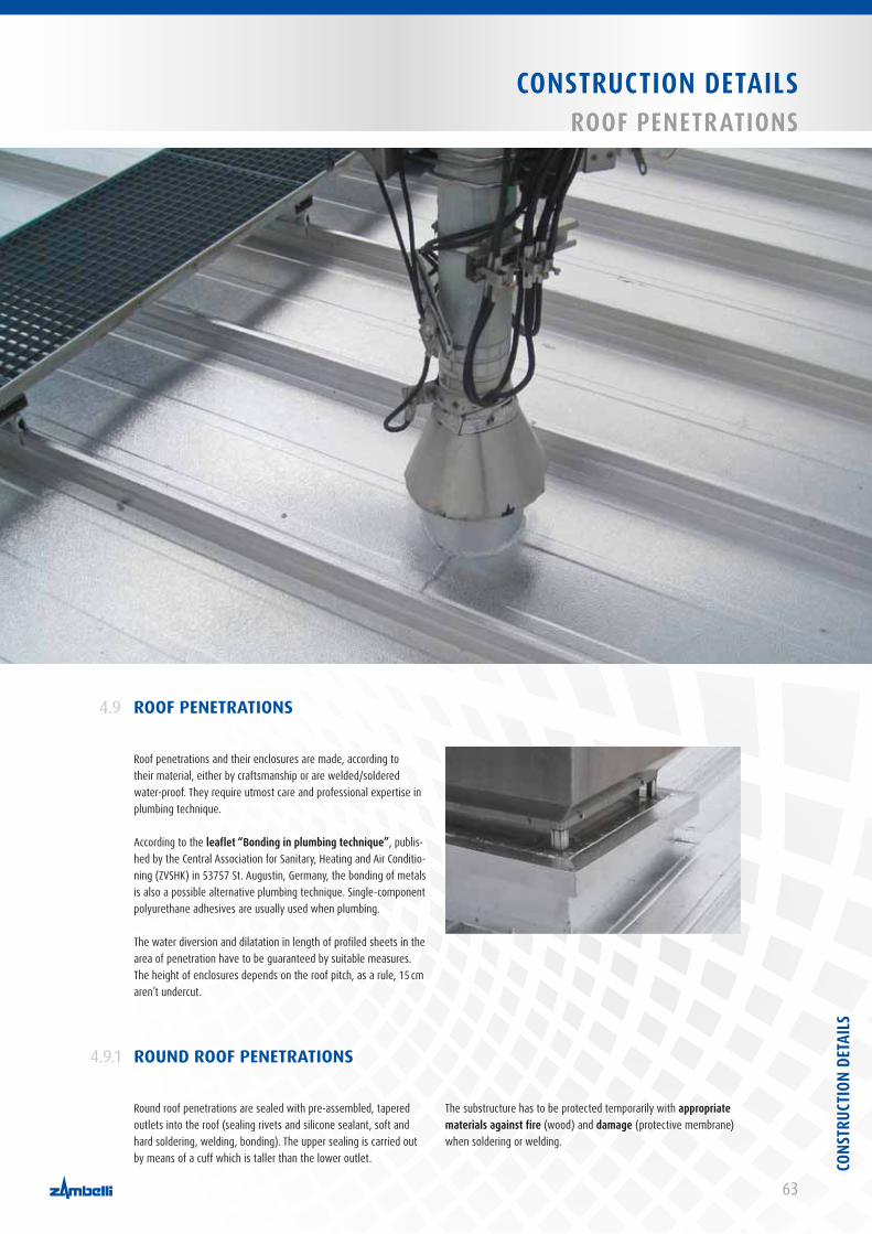
63
CONSTRUCTION DETAILSROOF PENETRATIONS
ROOF PENETRATIONS4.9
ROUND ROOF PENETRATIONS4.9.1
Roof penetrations and their enclosures are made, according to their material, either by craftsmanship or are welded/soldered water-proof. They require utmost care and professional expertise in plumbing technique.
According to the leaflet “Bonding in plumbing technique”, publis-hed by the Central Association for Sanitary, Heating and Air Conditio-ning (ZVSHK) in 53757 St. Augustin, Germany, the bonding of metals is also a possible alternative plumbing technique. Single-component polyurethane adhesives are usually used when plumbing.
The water diversion and dilatation in length of profiled sheets in the area of penetration have to be guaranteed by suitable measures. The height of enclosures depends on the roof pitch, as a rule, 15 cm aren’t undercut.
Round roof penetrations are sealed with pre-assembled, tapered outlets into the roof (sealing rivets and silicone sealant, soft and hard soldering, welding, bonding). The upper sealing is carried out by means of a cuff which is taller than the lower outlet.
The substructure has to be protected temporarily with appropriate materials against fire (wood) and damage (protective membrane) when soldering or welding.
CONS
TRUC
TION
DET
AILS
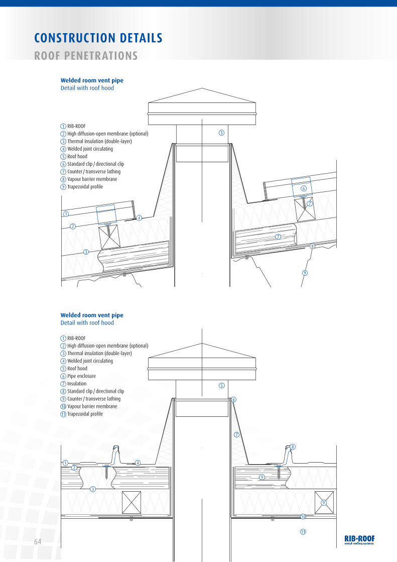
64
CONSTRUCTION DETAILSROOF PENETRATIONS
Welded room vent pipeDetail with roof hood
1 RIB-ROOF2 High diffusion-open membrane (optional)3 Thermal insulation (double-layer)4 Welded joint circulating5 Roof hood6 Standard clip / directional clip7 Counter / transverse lathing8 Vapour barrier membrane9 Trapezoidal profile
1
2
3
4
5
7
7
6
8
9
12
3
4
5
6
7
8
9
9
10
11
1 RIB-ROOF2 High diffusion-open membrane (optional)3 Thermal insulation (double-layer)4 Welded joint circulating5 Roof hood6 Pipe enclosure7 Insulation8 Standard clip / directional clip9 Counter / transverse lathing10 Vapour barrier membrane11 Trapezoidal profile
Welded room vent pipeDetail with roof hood
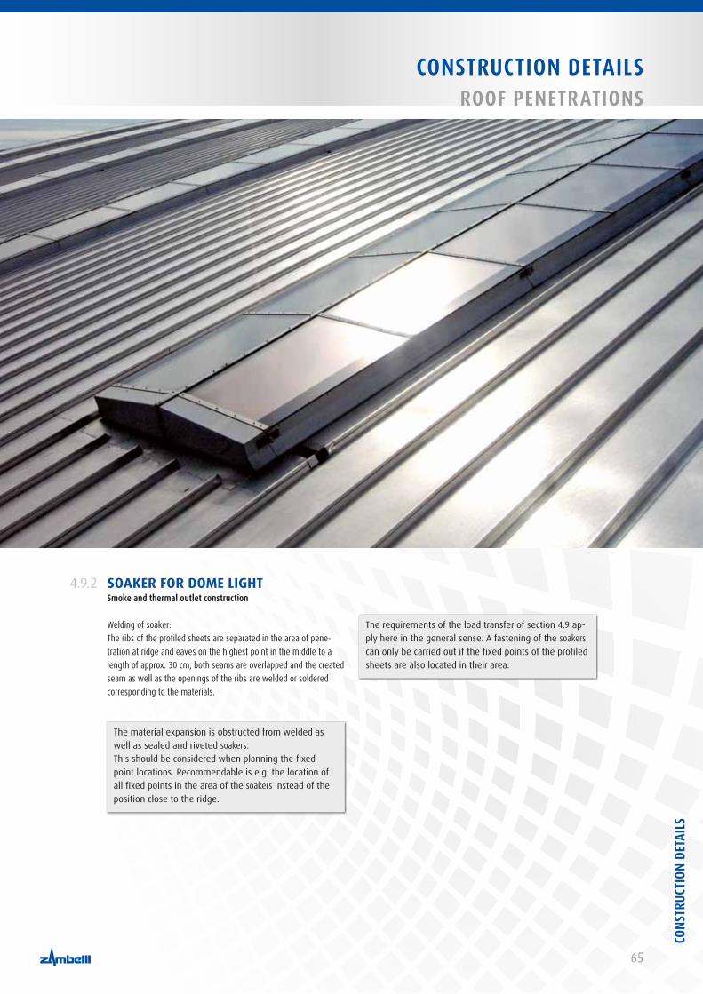
65
CONSTRUCTION DETAILSROOF PENETRATIONS
SOAKER FOR DOME LIGHTSmoke and thermal outlet construction
Welding of soaker:The ribs of the profiled sheets are separated in the area of pene-tration at ridge and eaves on the highest point in the middle to a length of approx. 30 cm, both seams are overlapped and the created seam as well as the openings of the ribs are welded or soldered corresponding to the materials.
4.9.2
The requirements of the load transfer of section 4.9 ap-ply here in the general sense. A fastening of the soakers can only be carried out if the fixed points of the profiled sheets are also located in their area.
The material expansion is obstructed from welded as well as sealed and riveted soakers. This should be considered when planning the fixed point locations. Recommendable is e.g. the location of all fixed points in the area of the soakers instead of the position close to the ridge.
CONS
TRUC
TION
DET
AILS
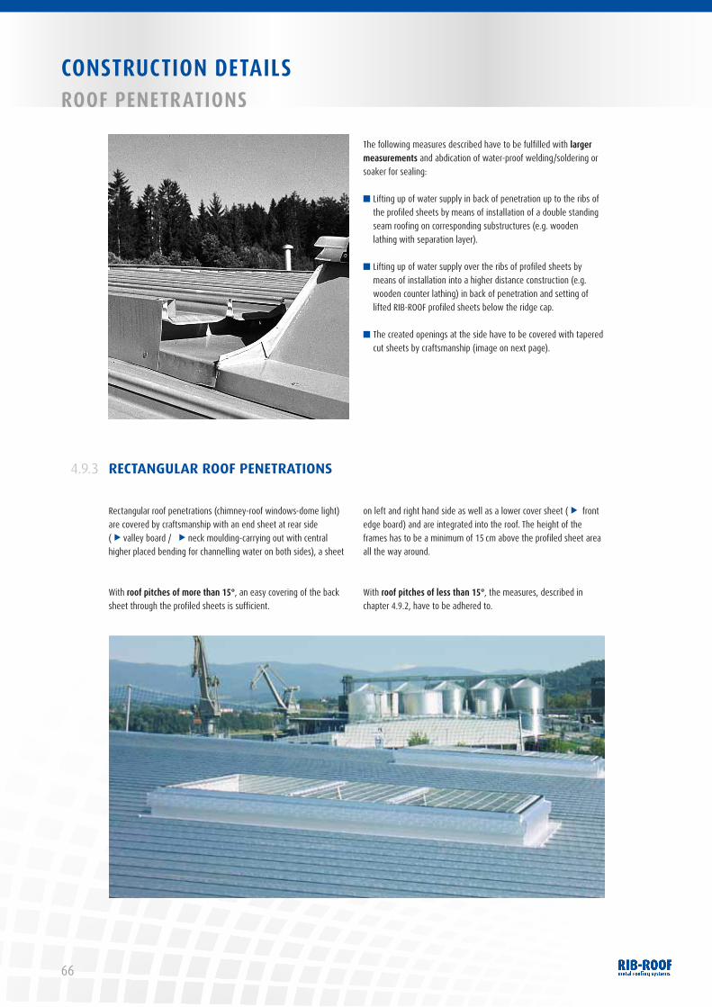
66
CONSTRUCTION DETAILSROOF PENETRATIONS
The following measures described have to be fulfilled with larger measurements and abdication of water-proof welding/soldering or soaker for sealing:
■ Lifting up of water supply in back of penetration up to the ribs of the profiled sheets by means of installation of a double standing seam roofing on corresponding substructures (e.g. wooden lathing with separation layer).
■ Lifting up of water supply over the ribs of profiled sheets by means of installation into a higher distance construction (e.g. wooden counter lathing) in back of penetration and setting of lifted RIB-ROOF profiled sheets below the ridge cap.
■ The created openings at the side have to be covered with tapered cut sheets by craftsmanship (image on next page).
RECTANGULAR ROOF PENETRATIONS4.9.3
Rectangular roof penetrations (chimney-roof windows-dome light) are covered by craftsmanship with an end sheet at rear side (
s
valley board / s
neck moulding-carrying out with central higher placed bending for channelling water on both sides), a sheet
on left and right hand side as well as a lower cover sheet (
s
front edge board) and are integrated into the roof. The height of the frames has to be a minimum of 15 cm above the profiled sheet area all the way around.
With roof pitches of more than 15°, an easy covering of the back sheet through the profiled sheets is sufficient.
With roof pitches of less than 15°, the measures, described in chapter 4.9.2, have to be adhered to.

67
CONSTRUCTION DETAILSROOF PENETRATIONS
1 Trapezoidal profiles2 Vapour barrier membrane3 Thermal separation layer4 Z-profile (diagonally)5 Thermal insulation (single-layer)6 RIB-ROOF7 Closure8 Sealing joint
9 Overhang strip10 Overhang sheet at ridge11 Overhang at edge12 Overhang at rear13 Bonding strip14 Standard clip / directional clip15 Sealing tape
1
234
5
6
7
8
9
1011
12
13
14
15
Protection with flow inhibited for roof pitches > 15°
Mantel piece(ridge and eaves)
CONS
TRUC
TION
DET
AILS
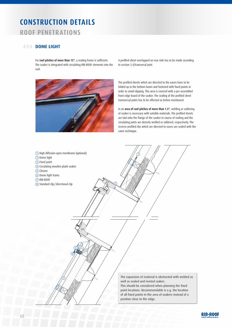
68
CONSTRUCTION DETAILSROOF PENETRATIONS
DOME LIGHT4.9.4
For roof pitches of more than 15°, a sealing frame is sufficient. The soaker is integrated with circulating RIB-ROOF elements into the roof.
A profiled sheet overlapped on rear side has to be made according to section 3.4/transvesal joint.
The profiled sheets which are directed to the eaves have to be folded up in the bottom boom and fastened with fixed points in order to avoid slipping. This area is covered with a pre-assembled front edge board of the soaker. The sealing of the profiled sheet transversal joints has to be effected as before mentioned.
In an area of roof pitches of more than 1.5°, welding or soldering of soaker is necessary with suitable materials. The profiled sheets are laid onto the flange of the soaker in course of roofing and the circulating joints are densely welded or soldered, respectively. The reverse profiled ribs which are directed to eaves are sealed with the same technique.
1
2
34
5
6
7
8
1 High diffusion-open membrane (optional)2 Dome light 3 Fixed point4 Circulating wooden plank soaker5 Closure6 Dome light frame7 RIB-ROOF8 Standard clip / directional clip
The expansion of material is obstructed with welded as well as sealed and riveted soakers. This should be considered when planning the fixed point locations. Recommendable is e.g. the location of all fixed points in the area of soakers instead of a position close to the ridge.

69
CONSTRUCTION DETAILSPHOTOvOLTAIC
Please also refer to the IFBS quality leaflet “Solar technique in light metal trade”. Advice for planning and structure, August 2012
PHOTOVOLTAIC ON RIB-ROOF4.10
The following details have to be considered when planning and installing:
■ Snow drifts and formation of ice: Before planning it has to be guaranteed that there will not arise snow drifts in bulk and large formation of ice between the PV modules due to a partially shaded and/or transversal frame in extreme winter conditions. With raised PV modules this can especially lead to flow inhibition or can reduce the effectiveness of the modules.
■ Freezing melting water: In winter times it could be possible at snow-covered roofs that in sunlit areas defrosting takes place. The resulting melting water is collected on its way towards eaves in the shaded areas of snow accumulation between the raised PV-modules. When the tem-perature later goes down, especially at night, the melting water freezes together with the snow accumulation which then results
in ice formation what, in turn, implicates further intensification of flow inhibition, especially with changing melting and frost periods.
■ Prefer roofs with thermal insulation:
Sufficiently insulated roofs and dome lights/light tapes without any larger thermal bridges and without non-insulated roof over-hangs are preferred, so that the above-mentioned problems can be avoided during winter.
■ General recommendation: A roof with highly diffusion-open protective sheets is the best solution with raised systems for snowy regions. A realization of eaves with an at least 3 m wide, highly diffusion-open protective sheet is here the minimum solution.
CONS
TRUC
TION
DET
AILS
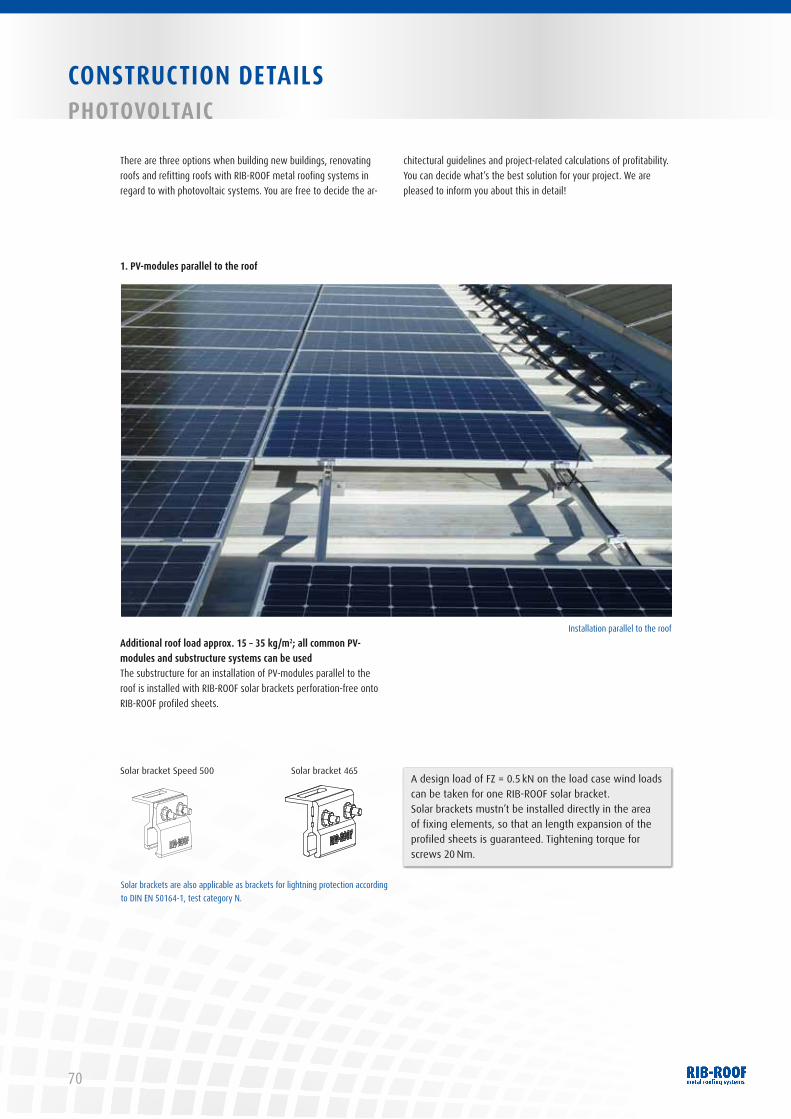
70
CONSTRUCTION DETAILSPHOTOvOLTAIC
There are three options when building new buildings, renovating roofs and refitting roofs with RIB-ROOF metal roofing systems in regard to with photovoltaic systems. You are free to decide the ar-
chitectural guidelines and project-related calculations of profitability. You can decide what‘s the best solution for your project. We are pleased to inform you about this in detail!
1. Pv-modules parallel to the roof
Additional roof load approx. 15 – 35 kg/m2; all common Pv-modules and substructure systems can be used The substructure for an installation of PV-modules parallel to the roof is installed with RIB-ROOF solar brackets perforation-free onto RIB-ROOF profiled sheets.
Installation parallel to the roof
Solar brackets are also applicable as brackets for lightning protection according to DIN EN 50164-1, test category N.
Solar bracket Speed 500 Solar bracket 465A design load of FZ = 0.5 kN on the load case wind loads can be taken for one RIB-ROOF solar bracket. Solar brackets mustn’t be installed directly in the area of fixing elements, so that an length expansion of the profiled sheets is guaranteed. Tightening torque for screws 20 Nm.
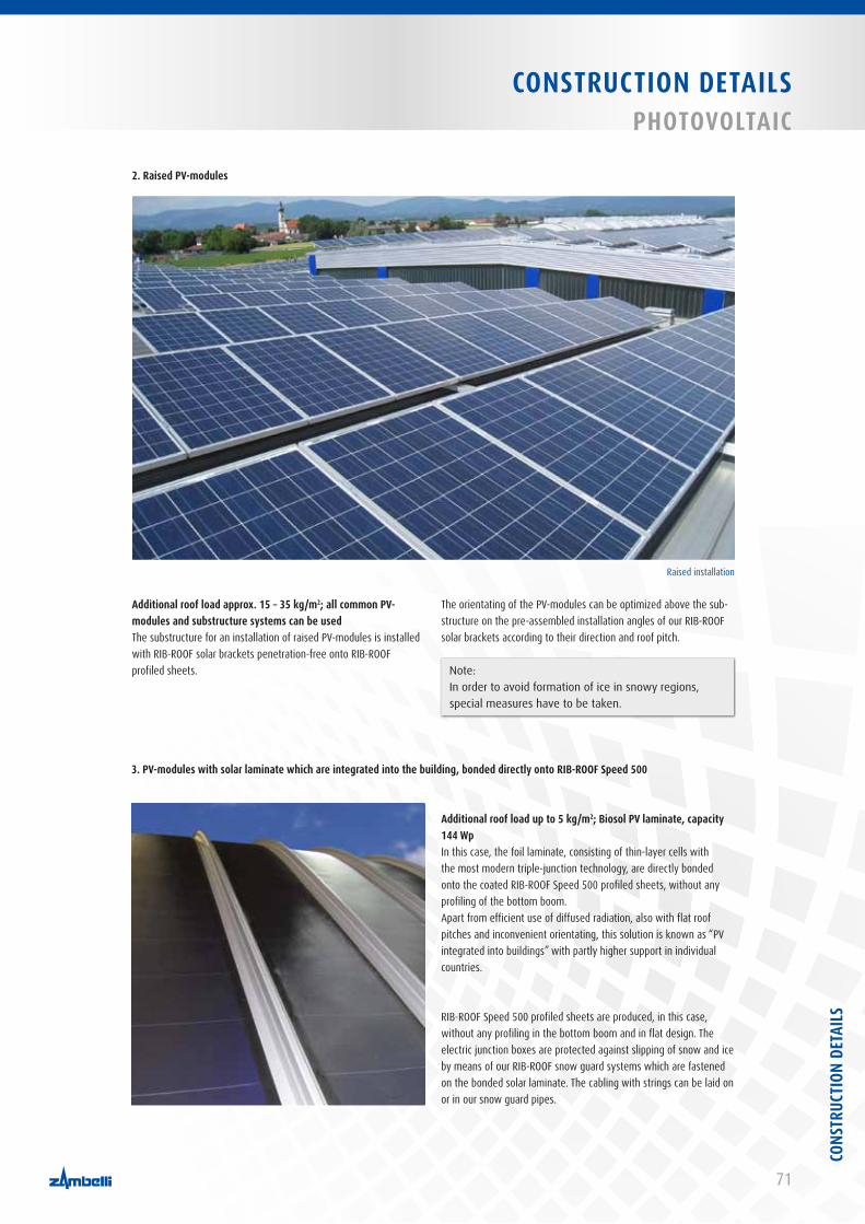
71
CONSTRUCTION DETAILSPHOTOvOLTAIC
2. Raised Pv-modules
Additional roof load approx. 15 – 35 kg/m2; all common Pv-modules and substructure systems can be usedThe substructure for an installation of raised PV-modules is installed with RIB-ROOF solar brackets penetration-free onto RIB-ROOF profiled sheets.
Additional roof load up to 5 kg/m2; Biosol Pv laminate, capacity 144 WpIn this case, the foil laminate, consisting of thin-layer cells with the most modern triple-junction technology, are directly bonded onto the coated RIB-ROOF Speed 500 profiled sheets, without any profiling of the bottom boom.Apart from efficient use of diffused radiation, also with flat roof pitches and inconvenient orientating, this solution is known as “PV integrated into buildings” with partly higher support in individual countries.
RIB-ROOF Speed 500 profiled sheets are produced, in this case, without any profiling in the bottom boom and in flat design. The electric junction boxes are protected against slipping of snow and ice by means of our RIB-ROOF snow guard systems which are fastened on the bonded solar laminate. The cabling with strings can be laid on or in our snow guard pipes.
The orientating of the PV-modules can be optimized above the sub-structure on the pre-assembled installation angles of our RIB-ROOF solar brackets according to their direction and roof pitch.
3. Pv-modules with solar laminate which are integrated into the building, bonded directly onto RIB-ROOF Speed 500
Raised installation
Note:In order to avoid formation of ice in snowy regions, special measures have to be taken.
CONS
TRUC
TION
DET
AILS
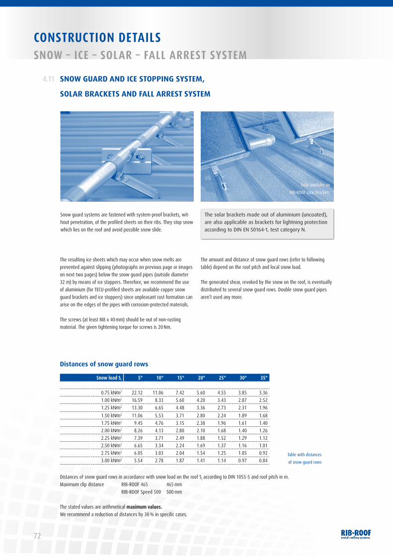
72
CONSTRUCTION DETAILSSNOW – ICE – SOLAR – FALL ARREST SYSTEM
SNOW GUARD AND ICE STOPPING SYSTEM,
SOLAR BRACKETS AND FALL ARREST SYSTEM
4.11
Snow guard systems are fastened with system-proof brackets, wit-hout penetration, of the profiled sheets on their ribs. They stop snow which lies on the roof and avoid possible snow slide.
The resulting ice sheets which may occur when snow melts are prevented against slipping (photographs on previous page or images on next two pages) below the snow guard pipes (outside diameter 32 m) by means of ice stoppers. Therefore, we recommend the use of aluminium (for TECU-profiled sheets are available copper snow guard brackets and ice stoppers) since unpleasant rust formation can arise on the edges of the pipes with corrosion-protected materials.
The screws (at least M8 x 40 mm) should be out of non-rusting material. The given tightening torque for screws is 20 Nm.
The amount and distance of snow guard rows (refer to following table) depend on the roof pitch and local snow load.
The generated shear, revoked by the snow on the roof, is eventually distributed to several snow guard rows. Double snow guard pipes aren’t used any more.
The solar brackets made out of aluminium (uncoated), are also applicable as brackets for lightning protection according to DIN EN 50164-1, test category N.
Solar modules on RIB-ROOF solar brackets
Distances of snow guard rows
Snow load Si 5° 10° 15° 20° 25° 30° 35°
0.75 kN⁄m2 22.12 11.06 7.42 5.60 4.55 3.85 3.361.00 kN⁄m2 16.59 8.33 5.60 4.20 3.43 2.87 2.521.25 kN⁄m2 13.30 6.65 4.48 3.36 2.73 2.31 1.961.50 kN⁄m2 11.06 5.53 3.71 2.80 2.24 1.89 1.681.75 kN⁄m2 9.45 4.76 3.15 2.38 1.96 1.61 1.402.00 kN⁄m2 8.26 4.13 2.80 2.10 1.68 1.40 1.262.25 kN⁄m2 7.39 3.71 2.49 1.88 1.52 1.29 1.122.50 kN⁄m2 6.65 3.34 2.24 1.69 1.37 1.16 1.012.75 kN⁄m2 6.05 3.03 2.04 1.54 1.25 1.05 0.923.00 kN⁄m2 5.54 2.78 1.87 1.41 1.14 0.97 0.84
Distances of snow guard rows in accordance with snow load on the roof Si according to DIN 1055-5 and roof pitch in m.Maximum clip distance RIB-ROOF 465 465 mm RIB-ROOF Speed 500 500 mm
The stated values are arithmetical maximum values.We recommend a reduction of distances by 30 % in specific cases.
Table with distances of snow guard rows
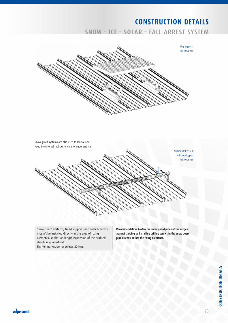
73
CONSTRUCTION DETAILSSNOW – ICE – SOLAR – FALL ARREST SYSTEM
Snow guard system with ice stoppers
RIB-ROOF 465
Step supports RIB-ROOF 465
Snow guard systems are also used to relieve and keep the internal roof gutter clear of snow and ice.
Snow guard systems, tread supports and solar brackets mustn’t be installed directly in the area of fixing elements, so that an length expansion of the profiled sheets is guaranteed. Tightening torque for screws 20 Nm.
Recommendation: Fasten the snow guard pipes at the verges against slipping by installing drilling screws in the snow guard pipe directly before the fixing elements.
CONS
TRUC
TION
DET
AILS
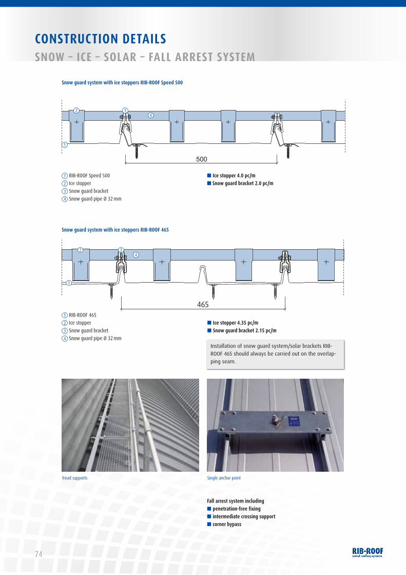
74
CONSTRUCTION DETAILSSNOW – ICE – SOLAR – FALL ARREST SYSTEM
Tread supports Single anchor point
■ Ice stopper 4.0 pc/m■ Snow guard bracket 2.0 pc/m
■ Ice stopper 4.35 pc/m■ Snow guard bracket 2.15 pc/m
Fall arrest system including■ penetration-free fixing■ intermediate crossing support■ corner bypass
465
1
2 34
Snow guard system with ice stoppers RIB-ROOF 465
Snow guard system with ice stoppers RIB-ROOF Speed 500
500
1 RIB-ROOF 4652 Ice stopper3 Snow guard bracket4 Snow guard pipe Ø 32 mm
1 RIB-ROOF Speed 5002 Ice stopper3 Snow guard bracket4 Snow guard pipe Ø 32 mm
1
2 34
Installation of snow guard system/solar brackets RIB-ROOF 465 should always be carried out on the overlap-ping seam.
75
CONSTRUCTION DETAILSFLASHINGS
You will find detailed drawings, especially for flashings, with standard measurements in our order form at:www.bestellblatt-kantteile.zambelli.de
FLASHINGS4.12
CONS
TRUC
TION
DET
AILS

76
INDEX
AAccessibility ................................................................................... 36, 47Accessories ...........................................................................................17Alu-zinc ........................................................................................ 7, 8, 14Alu-zinc alloy ........................................................................................14Anti-condensation......................................................................... 21, 51Arris ......................................................................................... 51, 53, 62Attica ....................................................................................... 58, 59, 61
BBending radii for flashings ..................................................................14Bottom boom .................................... 38, 39, 43, 46, 47, 55, 56, 68, 71Bonding ......................................................................................... 15, 63Bracket for lightning protection ..........................................................70
CClip distances .....................................................................28-36, 38, 40Closures ................................................................................................53Coils ......................................................................................................14Colour-coated ................................................................................ 14, 15Compressed thermal insulation ................................................... 22, 23Contact corrosion ...................................................................................7Copper ..................................................7, 12, 14, 15, 26, 32, 36, 62, 72Corner and edge area of roof ..................................................28-36, 44Corrosion protection class .....................................................................7Corrugation ...........................................................................................57Cover sheet for verge ................................................................... 56, 57Curved profiled sheets ............................................................ 26, 27, 40Cutting disc ..........................................................................................14Cutting edges ................................................................................ 14, 72
D(high) Diffusion-open protective sheet ....9, 18, 22, 23, 27, 55, 59, 69Diffusion effect ....................................................................................23Dilatation ....................................................................................... 14, 16DIN 18807 ..............................................................................................7Directional clip/profile system Speed 500 .......... 18, 24, 33, 42, 43, 54Distance profiles ....................................................................... 9, 19, 41Diverting water ....................................................................................63Dome light ..................................................................15, 65, 66, 68, 69Double pitch ridge with/without ventilation opening ................ 50, 51Drilling chips and chip cuttings ...........................................................14
EEaves ............................................................................................. 39, 54Eaves strip ............................................................................................56Edge and corner area of roof ...................................................28-36, 44Extension gadgets ........................................................................ 50, 60Extra long profiled sheets ...................................................... 13, 17, 47
FFall arrest system .........................................................5, 17, 25, 72, 74Fastening material ...............................................................................10Fastening technology ..........................................................................15Fixed point ............................................................38, 41-46, 56, 65, 68Fixed point clip/profile .................................................................. 24, 45Flashings ...........................................................................12, 13, 25, 75Flat clip border system Speed 500 ............................19, 24, 28, 29, 41Folding down ................................................................................ 38, 46Folding up of profiled sheets ....................................................... 38, 46Formation of ice ...................................................................................69
GGalvanised ....................................................................................... 8, 14
IIce stopping system ...................................................................... 55, 72Inspection.............................................................................................47Internal gutters ............................................................................. 60, 61
JJoints ............................................................................................. 19, 41Joint sealing .........................................................................................47
LLacquer system ....................................................................................15Length expansion .................................... 42-45, 47, 56, 60, 63, 70, 73Load transfer ........................................................................................65
MMantel piece ........................................................................................67Maintenance ........................................................................................47Material expansion ...........................................................45, 46, 65, 68Minimum bending radii ................................................................ 14, 26Minimum roof pitch .............................................................................22Mobile rollforming ...............................................................................13
OOverhang strip ........................................................................ 58, 59, 67

77
INDEX
PPerforated clip border system Speed 500 .................19, 24, 28, 29, 42Photovoltaic modules .................................................................... 69-71Profiled sheet length ........................................................12, 42, 43, 45Profiling at site .....................................................................................17Protective sheet ................................... 9, 18, 22, 23, 27, 52, 55-57, 69Puddle formation .......................................................................... 22, 47
RRectangular roof penetration ..............................................................66RIB-ROOF 465 ....................................................................24, 44, 45, 49RIB-ROOF Speed 500..........................................................24, 38-43, 48Ridge cap ...............................................................25, 42-46, 48-53, 66Rigid insulation boards ...............................................19, 21, 41, 42, 60Rivet ......................................................... 10, 38, 42, 44-47, 55, 56, 63Roof penetrations ......................................................................9, 63-68Roof renovation ...................................................................................70Room ventilation pipe .........................................................................64Round roof penetration .......................................................................63
SSafety measures ..................................................................................60Screws ......................................... 10, 27, 38, 41, 42, 44, 46, 70, 72, 73Sealing tapes .......................................................................................47Secondary melt water............................................................... 9, 12, 55Separation layers ............................................................................ 7, 55Single pitch ridge ........................................................51, 55, 56, 58, 59Sliding clips .................................................................38, 39, 40, 44, 56Sloped steps .................................................................................. 55, 56Snow guard system ...................................................................... 72, 73Soaker ..................................................................................... 65, 66, 68Solar bracket ............................................................................25, 70-74Soldering ...........................................................................15, 62, 66, 68Soundproofing ........................................................................... 9, 22, 23Soundproofing when building houses ................................................23Spans ........................................................................................28-37, 44Spreader beams ........................................................................ 5, 11, 12Standard clip system 465 .................................................24, 44, 49, 54Standard clip system Speed 500 ......................................24, 38, 48, 54Start clip system 465 .................................................................... 24, 44Steel trapezoidal profiles .....................................................................10Storage .......................................................................................... 11, 12Substructure ........................................................................9, 10, 18, 36
TTapered profiled sheets .......................................................................26Temperature-related length expansions ...............................................7Tensions .................................................................................. 16, 17, 57Titanium zinc .................................................... 7, 12, 14, 15, 26, 36, 62Tool for folding down ...........................................................................55Top chord ................................................................................. 19, 41, 56Transport ....................................................................................... 11, 47Transversal joint ..................................................................7, 17, 47, 68Tread support ................................................................................ 25, 73
UUnloading .............................................................................................12U-values............................... ................................................................23
VValleys ..................................................................................................62Ventilation ridge cap ............................................................................25Verge .................................................. 23, 25, 40, 44, 48, 51, 56-59, 73Verge plank ..........................................................................................57
WWall connection at side .......................................................................58Welding .......................................................................15, 22, 62, 66, 68Wind load ...........................................................................28-35, 38, 44
78
BlindtextBlindtext
Zambelli RIB-ROOF GmbH & Co. KG Hans-Sachs-Straße 3 + 5 94569 Stephansposching Germany
Phone +49 (99 31) 8 95 90 - 0 Fax +49 (99 31) 8 95 90 - 49 E-mail [email protected] www zambelli.com
1|20
13Te
chni
cal a
men
dmen
ts, e
rrors
and
prin
ting
mist
akes
are
rese
rved
.
RIB-ROOFMetal roofing systems
Roof Drainage Shelving Systems Industrial Metal Works


