Integrated Control Solutions & Energy Savings Kit OEM KEC NO POWER & SIGNAL CABLES TOGETHER READ CAREFULLY IN THE TEXT! Manuale d’uso User manual Software per raffreddamento evaporativo Software for Evaporative Cooling
Transcript
I n t e g r a t e d C o n t r o l S o l u t i o n s & E n e r g y S a v i n g s
Kit OEM KEC
NO POWER
& SIGNAL
CABLES
TOGETHER
READ CAREFULLY IN THE TEXT!
Manuale d’uso
User manual
Software per raff reddamento evaporativo
Software for Evaporative Cooling
3
ITA
“software KEC” +030222165 - rel. 1.0 - 29/09/2015
AVVERTENZE
Gli umidifi catori CAREL Industries sono prodotti avanzati, il cui funzionamento
è specifi cato nella documentazione tecnica fornIta col prodotto o scaricabile,
anche anteriormente all’acquisto, dal sito internet www.carel.com. Ogni
prodotto CAREL Industries, in relazione al suo avanzato livello tecnologico,
necessIta di una fase di qualifi ca/confi gurazione/programmazione affi nché
possa funzionare al meglio per l’applicazione specifi ca. La mancanza di tale
fase di studio, come indicata nel manuale, può generare malfunzionamenti nei
prodotti fi nali di cui CAREL Industries non potrà essere ritenuta responsabile.
Il cliente (costruttore, progettista o installatore dell’equipaggiamento fi nale)
si assume ogni responsabilità e rischio in relazione alla confi gurazione del
prodotto per il raggiungimento dei risultati previsti in relazione all’installazione
e/o equipaggiamento fi nale specifi co. CAREL Industries in questo caso, previ
accordi specifi ci, può intervenire come consulente per la buona riuscIta della
installazione/start-up macchina/utilizzo, ma in nessun caso può essere ritenuta
responsabile per il buon funzionamento dell’umidifi catore ed impianto fi nale
qualora non siano state seguite le avvertenze o raccomandazioni descritte
in questo manuale, o in altra documentazione tecnica del prodotto. In
particolare, senza esclusione dell’obbligo di osservare le anzidette avvertenze
o raccomandazioni, per un uso corretto del prodotto si raccomanda di
• Defl ettori per ugelli: consentono di aumentare l’angolo del getto a
cono e di aumentare la superfi cie dello scambiatore investita dal fl usso
di acqua nebulizzata.
Fig. 1.f
1.5 Caratteristiche principaliIn breve:
• Pressione di lavoro massima di 14 bar;
• Richiesta via seriale dal controllo Master dell’unità di trattamento aria;
• Comunicazione seriale con l’inverter, che garantisce la
parametrizzazione diretta di quest’ultimo da parte del controllo KEC e
la gestione degli allarmi;
• Misuratore di portata, che permette il controllo preciso della quantità
di acqua spruzzata e la gestione avanzata della mancanza acqua;
• Disponibilità di kit di componenti del rack di distribuzione, come ugelli,
raccordi, staff e per garantire la massima fl essibilità nella costruzione e
nella distribuzione dell’acqua spruzzata;
• Disponibilità di librerie software per l’integrazione via seriale (protocollo
Modbus) del controllo con altri regolatori della unità di trattamento
aria, sia in ambienti CAREL 1Tool che c.Suite.
9
ITA
“software KEC” +030222165 - rel. 1.0 - 29/09/2015
1.6 Architettura Il sistema KEC riceve il segnale di richiesta di produzione via seriale
dal controllo Master della unità di trattamento aria e attiva la pompa
modulandone la portata. La stazione di pompaggio, oltre alle valvole di
carico e scarico del cabinet, comanda le valvole di carico/scarico del/dei
rack. Comanda inoltre le valvole di scarico di linea (in.drain step1/2), utili
nel caso di installazioni ove la stazione di pompaggio si trovi più in basso
del rack di distribuzione(*).
(*) in questo caso la sola apertura della valvola di scarico della stazione di
pompaggio non svuota la linea idraulica..
12
3
4
6M 3~
7
15 14
12
11
13
8
10
1/2"
STEP 1 STEP 2
5
17
16
18
19
OUTSTEP 1
OUTSTEP 2
IN. DRAINSTEP 2
IN DRAINSTEP 1
DRAIN STEP 1
DRAIN STEP 2
9
C1
NO
1
NO
2
NO
4
C4 C7
NO
7
C7
NO
8
C8
NC8
G G0 U
1U
2
U3 G
ND
+VD
C
+Vte
rm
GN
D
+5 VR
EF
U4
GN
D
U5
GN
D
VG VG0
Y1 Y2 Y3 Y4 ID1
ID2
ID3
ID4
ID5
ID6
ID7
ID8
IDC1
J1 J24 J3 J4 J5
J14
J10
J13J12 J15
B M S card
J11 pLAN
4 3 2 1
C4
WATER SUPPLY
MASTER: AHU controller
pGD1 terminalfor commissioning
SLAVE: KEC controller
RACK: INSIDE AHU
PUMPSTATION
ELECTRONIC CONTROLLER+ INVERTER
1
2
3
6
11
12
5
14
10 913
15 1617
4
Q
24 Vac
230 Vac
2.5 A T
G G0
J1
100 VA Heat recoveryout temperature
J25 BMS2 J26 Fbus2
8
Fig. 1.g
1 Filtro acqua 6 Pompa 11 Termostato meccanico 16 Elettrovalvola di scarico rack step 12 Riduttore di pressione 7 Inverter 12 Sonda temperatura 17 Elettrovalvola di scarico rack step 23 Manometro bassa pressione 8 Regolatore tarabile alta pressione 13 Trasduttore di pressione 18 Scarico linea step 14 Elettrovalvola di carico 9 Elettrovalvola carico step 1 14 Manometro alta pressione 19 Scarico linea step 25 Misuratore di portata 10 Elettrovalvola carico step 2 15 Elettrovalvola di scarico Q Quadro elettrico
Tab. 1.c
10
ITA
“software KEC” +030222165 - rel. 1.0 - 29/09/2015
1.7 Schemi applicativi
1.7.1 IECIl controllo Master invia via seriale il segnale di richiesta modulante da 0 a
1000. Il KEC attiva la produzione e decide in base alla richiesta di attivare
uno o due step.
La sonda di temperatura all’uscita dello scambiatore va installata in caso
di regolazione (proporzionale o di temperatura) con controllo di portata.
T1H1
T2H2
T3H3
T4H4
IEC: STEP1 + STEP2
KEC
MASTER: AHU controller
C1
NO
1
NO
2
NO
3
C1
C4
NO
4
NO
5
NO
6
C4
C7
NO
7
C7
NO
8
C8
NC
8
G G0
U1
U2
U3
GN
D
+V
DC
+Vt
erm
GN
D
+5
VREF
U4
GN
D
U5
GN
D
VG
VG
0
Y1 Y2 Y3 Y4 ID1
ID2
ID3
ID4
ID5
ID6
ID7
ID8
IDC
1
J1 J24 J2 J3 J4 J5
J10
S
Fig. 1.h
1.7.2 DEC + IECIl controllo Master invia via seriale il segnale di richiesta modulante da 0 a
1000 e la stagione corrente. Il controllo KEC:
• se inverno attiva solo il DEC;
• se estate attiva solo l’IEC.
T1H1
T2H2
T3H3
T4H4
IEC: STEP 2
DEC: STEP 1
KEC
MASTER: AHU controller
C1
NO
1
NO
2
NO
3
C1
C4
NO
4
NO
5
NO
6
C4
C7
NO
7
C7
NO
8
C8
NC
8
G G0
U1
U2
U3
GN
D
+V
DC
+Vt
erm
GN
D
+5
VREF
U4
GN
D
U5
GN
D
VG
VG
0
Y1 Y2 Y3 Y4 ID1
ID2
ID3
ID4
ID5
ID6
ID7
ID8
IDC
1
J1 J24 J2 J3 J4 J5
J10
S
Fig. 1.i
Legenda
IEC Raff reddamento evaporativo indiretto T3/H3 Temperatura/umidità aria all’uscita dello scambiatore T2/H2 Temperatura/umidità aria di ripresaDEC Raff reddamento evaporativo diretto S Sonda di temperatura all’uscita dello scambiatoreT1/H1 Temperatura/umidità aria esterna T4/H4 Temperatura/umidità aria di espulsione
11
ITA
“software KEC” +030222165 - rel. 1.0 - 29/09/2015
2. INTERFACCIA UTENTE
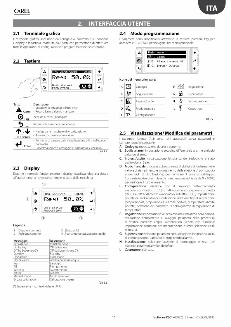
2.1 Terminale grafi coIl terminale grafi co, accessorio da collegare al controllo KEC, contiene
il display e la tastiera, costituita da 6 tasti, che permettono di eff ettuare
tutte le operazioni di confi gurazione e programmazione del controllo.
2.2 Tastiera
Tasto Descrizione
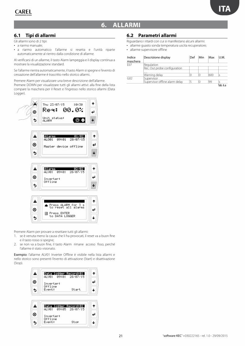
Alarm
• Visualizza la lista degli allarmi attivi
• Reset allarmi a riarmo manuale
PrgAccesso al menu principale
EscRitorno alla maschera precedente
/
UP / DOWN
• Naviga tra le maschere di visualizzazione
• Aumento / diminuzione valore
- Enter
• Permette di passare dalla visualizzazione alla modifi ca dei
parametri
• Conferma valore e passaggio al parametro successivoTab. 2.a
2.3 DisplayDurante il normale funzionamento il display visualizza, oltre alla data e
all’ora corrente, la richiesta corrente e lo stato della macchina.
1
2
3 4
Legenda
1 Data/ ora corrente 3 Stato unità2 Richiesta corrente 4 Icona menu tasti accesso rapido
Messaggio DescrizioneInitialization InizializzazioneOff by Key Off da tastieraOff by Supervisor(*) Off da Supervisione (*)Standby StandbyProduction Produzione Check water Verifi ca presenza acquaWash Lavaggio Fill RiempimentoWarning AvvertimentoAlarm AllarmeManual mode Modo manualeBypass calibration Calibrazione bypass
Tab. 2.b (*) Supervisore = controllo Master AHU
2.4 Modo programmazioneI parametri sono modifi cabili attraverso la tastiera: premere Prg per
accedere e UP/DOWN per navigare nel menu principale.
Icone del menu principale:
A. Orologio F. Regolazione
B. Soglia allarmi G. Supervisore
C. Ingressi/uscite H. Inizializzazione
D. Modo manuale I. Costruttore
E. Confi gurazione
Tab. 2.c
2.5 Visualizzazione/ Modifi ca dei parametriI parametri Utente (A...I) sono tutti accessibili senza password e
comprendono le categorie:
A. Orologio: impostazione data/ora corrente.
B. Soglia allarmi: impostazione setpoint, diff erenziale allarme antigelo
e ritardo allarme;
C. Ingressi/uscite: visualizzazione lettura sonde analogiche e stato
uscite digitali (relè).
D. Modo manuale: procedura che consente di abilitare singolarmente le
valvole di riempimento e svuotamento della stazione di pompaggio
e del rack di distribuzione, per verifi care il corretto cablaggio.
Consente inoltre di simulare da maschera una richiesta da 0 a 100%,
per verifi care il funzionamento;
E. Confi gurazione: selezione tipo di impianto: raff reddamento
evaporativo indiretto (I.E.C.) o raff reddamento evaporativo diretto
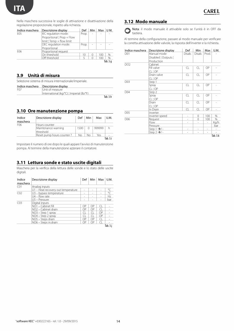
C03 Digital inputsNO1 – Cabinet fi ll OP OP CL -NO2 – Cabinet drain OP OP CL -NO3 – Step 1 spray CL CL OP -NO4 – Step 2 spray CL CL OP -NO5 – Steps drain OP OP CL -NO6 – Steps in.drain OP OP CL -
Tab. 3.j
3.12 Modo manuale
Nota: il modo manuale è attivabile solo se l’unità è in OFF da
tastiera.
Al termine della confi gurazione, passare al modo manuale per verifi care
la corretta attivazione delle valvole, la risposta dell’inverter e la richiesta.
Indice maschera Descrizione display Def Min Max U.M.D01 Manual mode
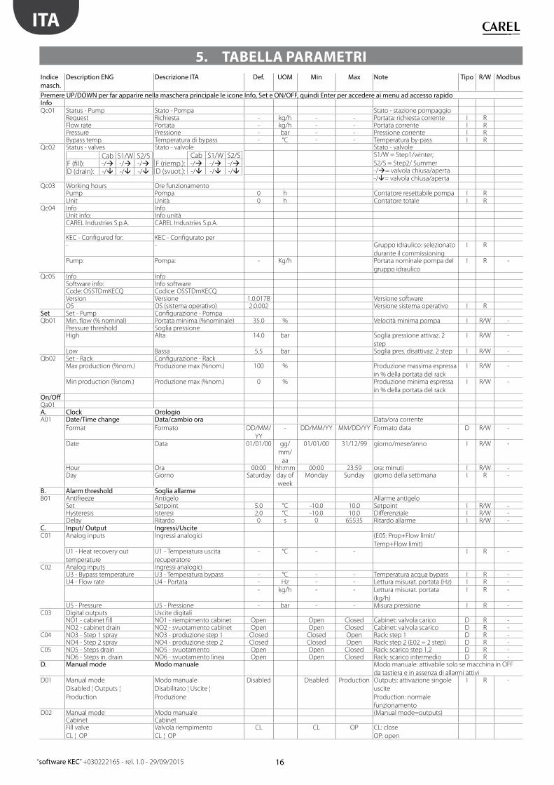
Description ENG Descrizione ITA Def. UOM Min Max Note Tipo R/W Modbus
Premere UP/DOWN per far apparire nella maschera principale le icone Info, Set e ON/OFF, quindi Enter per accedere ai menu ad accesso rapidoInfoQc01 Status - Pump Stato - Pompa Stato - stazione pompaggio
Request Richiesta - kg/h - - Portata: richiesta corrente I RFlow rate Portata - kg/h - - Portata corrente I RPressure Pressione - bar - - Pressione corrente I RBypass temp. Temperatura di bypass - °C - - Temperatura by-pass I R
Qc05 Info InfoSoftware info: Info softwareCode: OSSTDmKECQ Codice: OSSTDmKECQVersion Versione 1.0.017B Versione softwareOS OS (sistema operativo) 2.0.002 Versione sistema operativo I R
Set Set - Pump Confi gurazione - PompaQb01 Min. fl ow (% nominal) Portata minima (%nominale) 35.0 % Velocità minima pompa I R/W -
Pressure threshold Soglia pressioneHigh Alta 14.0 bar Soglia pressione attivaz. 2
step
I R/W -
Low Bassa 5.5 bar Soglia pres. disattivaz. 2 step I R/W -Qb02 Set - Rack Confi gurazione - Rack
Max production (%nom.) Produzione max (%nom.) 100 % Produzione massima espressa
in % della portata del rack
I R/W -
Min production (%nom.) Produzione max (%nom.) 0 % Produzione minima espressa
in % della portata del rack
I R/W -
On/Off Qa01A. Clock OrologioA01 Date/Time change Data/cambio ora Data/ora corrente
Format Formato DD/MM/
YY
- DD/MM/YY MM/DD/YY Formato data D R/W -
Date Data 01/01/00 gg/
mm/
aa
01/01/00 31/12/99 giorno/mese/anno I R/W -
Hour Ora 00:00 hh:mm 00:00 23:59 ora: minuti I R/W -Day Giorno Saturday day of
week
Monday Sunday giorno della settimana I R -
B. Alarm threshold Soglia allarmeB01 Antifreeze Antigelo Allarme antigelo
Set Setpoint 5.0 °C -10.0 10.0 Setpoint I R/W -Hysteresis Isteresi 2.0 °C -10.0 10.0 Diff erenziale I R/W -Delay Ritardo 0 s 0 65535 Ritardo allarme I R/W -
C. Input/ Output Ingressi/UsciteC01 Analog inputs Ingressi analogici (E05: Prop+Flow limit/
Temp+Flow limit)U1 - Heat recovery out
temperature
U1 - Temperatura uscita
recuperatore
- °C - - I R -
C02 Analog inputs Ingressi analogiciU3 - Bypass temperature U3 - Temperatura bypass - °C - - Temperatura acqua bypass I R -U4 - Flow rate U4 - Portata - Hz - - Lettura misurat. portata (Hz) I R -
- kg/h - - Lettura misurat. portata
(kg/h)
I R -
U5 - Pressure U5 - Pressione - bar - - Misura pressione I R -C03 Digital outputs Uscite digitali
NO1 - cabinet fi ll NO1 - riempimento cabinet Open Open Closed Cabinet: valvola carico D R -NO2 - cabinet drain NO2 - svuotamento cabinet Open Open Closed Cabinet: valvola scarico D R -
C04 NO3 - Step 1 spray NO3 - produzione step 1 Closed Closed Open Rack: step 1 D R -NO4 - Step 2 spray NO4 - produzione step 2 Closed Closed Open Rack: step 2 (E02 = 2 step) D R -
C05 NO5 - Steps drain NO5 - svuotamento Open Open Closed Rack: scarico step 1,2 D R -NO6 - Steps in. drain NO6 - svuotamento linea Open Open Closed Rack: scarico intermedio D R -
D. Manual mode Modo manuale Modo manuale: attivabile solo se macchina in OFF
da tastiera e in assenza di allarmi attiviD01 Manual mode
Disabled ¦ Outputs ¦
Production
Modo manuale
Disabilitato ¦ Uscite ¦
Produzione
Disabled Disabled Production Outputs: attivazione singole
uscite
Production: normale
funzionamento
I R -
D02 Manual mode Modo manuale (Manual mode=outputs)Cabinet CabinetFill valve
CL ¦ OP
Valvola riempimento
CL ¦ OP
CL CL OP CL: close
OP: open
5. TABELLA PARAMETRI
17
ITA
“software KEC” +030222165 - rel. 1.0 - 29/09/2015
Indice
masch.
Description ENG Descrizione ITA Def. UOM Min Max Note Tipo R/W Modbus
D02 Drain valve
CL ¦ OP
Valvola svuotamento
CL ¦ OP
CL CL OP
D03 Manual mode Modo manuale (Manual mode=outputs)Step 1 Step 1Spray
CL ¦ OP
Produzione
CL ¦ OP
CL CL OP
D04 Manual mode Modo manuale (Manual mode=outputs)Step 2 Step 2Spray
CL ¦ OP
Produzione
CL ¦ OP
CL CL OP
Drain
CL ¦ OP
Svuotamento
CL ¦ OP
CL CL OP
In Drain Svuotamento di linea CL CL OPD05 Manual mode Modo manuale (Manual mode=outputs)
Inverter InverterInverter speed Velocità inverter - % 0 100 I R/W -
E03 Distrib. system Sistema di distribuzione (E01=IEC+DEC)Nominal fl ow rate IEC Portata nominale IEC 100 kg/h 0 100Nominal fl ow rate DEC Portata nominale DEC 100 kg/h 0 100
E04 Distribution system Sistema di distribuzionePressure setpoint Setpoint di pressioneHigh Alto 14 bar 0 20 Soglia press. attivaz. 2° step I R/W -Low Basso 5.5 bar 0 20 Soglia press. disattivaz. 2° step I R/W -
E05 Regulation RegolazioneIEC Regulation mode:
Proportional ¦ Prop + Flow
Limit ¦ Temp + Flow limit
Modo regolazione IEC
Proporzionale ¦ Proporzionale +
limite portata ¦
temperatura + limite portata
Propor. Propor. Temp+Flow
Limit
I R/W -
DEC regulation mode Modo regolazione DEC Propor. I R -E06 Regulation Regolazione (E05=Proportional+fl ow limit/
Temp+fl ow limit)
I R
Proportional request Richiesta proporzionaleON Threshold Soglia attivazione 10 % 0 100 % richiesta-->reg.prop. ON I R/W -OFF Threshold Soglia disattivazione 5 % 0 100 % richiesta-->reg.prop. OFF I R/W -
proportional+fl ow limit)Rec. out probe confi g. Confi gurazione sonda uscita
recuperatoreType
NTC ¦ 0-1 V ¦ 0-10 V ¦ 4-20 mA
¦ 0-5 V
Tipo
NTC ¦ 0-1 V ¦ 0-10 V ¦ 4-20 mA
¦ 0-5 V
NTC - NTC 0-5 V I R/W -
Off set Off set 0.0 °C -99.9 99.9 I R/W -Warning delay Ritardo warning 0 s 0 600 I R/W -
E08 Regulation Regolazione (E05=Temp+fl ow limit)Temperature regulation Regolazione temperaturaSetpoint Setpoint 15.0 °C 0 100 I R/W -Diff erential Diff erenziale 10.0 °C 0 100 I R/W -Prop. Band Banda proporzionale 5.0 °C 0 999.9 I R/W -Neutral zone Zona neutra 1.0 °C 0 999.9 I R/W -Integral time Tempo integrale 300 s 0 999.9 I R/W -
F. Regulation RegolazioneF01 Pump settings Impostazioni pompa
Prod. limits Limiti di produzioneNominal pump fl ow rate Portata nom. della pompa 100 kg/h 50 1000 I R/W -Min fl ow (% nom.) Velocità min pompa (%) 35 % 0 100 I R/W -Max fl ow (% nom.) Velocità max pompa (%) 100 % Min fl ow 100 I R/W -
F02 Pump settingsEnable fi ll
Yes ¦ No
Abilita proc. riempimento
Si ¦ No
Yes Yes No Yes ¦ No D R/W -
Wash mode
Drain only ¦ Daily ¦ Periodic
Abilita proc. lavaggio
Solo svuotamento ¦ Giornaliero
¦ Periodico
Periodic Periodic Daily I R/W -
F03 Pump settings Impostazioni pompaFill time Tempo riempimento 2 min 0 99 Durata riempimento I R/W -Wash time Tempo lavaggio 2 min 0 99 Durata lavaggio I R/W -Time Ora inizio 00:00 hh:mm 00:00 23:59Inactivity threshold Soglia inattività 24 h 0 99 Soglia di inattività per
attivazione lavaggio
periodico
I R/W -
F04 Water check Verifi ca presenza acquaWater check time Durata verifi ca presenza acqua 15 s 0 999 Durata check presenza acqua I R/W -
18
ITA
“software KEC” +030222165 - rel. 1.0 - 29/09/2015
Indice
masch.
Description ENG Descrizione ITA Def. UOM Min Max Note Tipo R/W Modbus
F04 Missing water retry
timeout
Timeout verifi ca presenza
acqua
10 min 0 999 Timeout (tempo base) per
verifi ca automatica presenza
acqua
I R/W -
F05 Winterization WinterizationWinterization timeout Timeout winterization 5 min 0 180 Durata massima procedura di
winterization
I R/W -
Run winterization ? Attiva winterization ? No - No Yes Richiesta attivazione
winterization
D R/W -
F06 Hours counter ContaoreMaintenance warning
threshold
Soglia warning manutenzione 1500 h 0 999999 Soglia avviso manutenzione
sistema
I R/W -
Reset pump hours counter ? Reset contaore pompa ? No - No Yes Reset contaore pompa D R/W -F07 Unit of measure
International (kg/°C) ¦
Imperial (lb/°F)
Unità di misura
Internazionale (kg/°C) ¦
Imperiale (lb/°F)
Internat. - - - - D R/W -
G01 Supervisor SupervisoreProtocol Protocollo Modbus Protocollo di comunicazione D R -Address Indirizzo 1 1 254 I R/W -Baudrate (porta BMS2)
1200 ¦ 2400 ¦ 4800 ¦ 9600 ¦
19200 ¦ 38400
Baudrate (porta BMS2)
1200 ¦ 2400 ¦ 4800 ¦ 9600 ¦
19200 ¦ 38400
19200 1200 38400 I R/W -
Parity
None ¦ Odd ¦ Even
Parità
Nessuna ¦ Dispari ¦ Pari
None None Even I R/W -
Stop bits Bit di stop 2 1 2 I R/W -G02 Supervisor Supervisore
Supervisor offl ine alarm delay Ritardo allarme supervisore
offl ine
5 s 0 99 Vedere cap. Allarmi I R/W -
H. Initialization InizializzazioneH01 Hydraulic group
NO MODEL (=before
commissioning) ¦
KEC005DH*0 ¦ KEC005UH*0 ¦
KEC010DH*0 ¦ KEC010UH*0 ¦
KEC020DH*0 ¦ KEC020UH*0 ¦
KEC040DH*0 ¦ KEC040UH*0 ¦
KEC080DH*0 ¦ KEC080UH*0 ¦
KEC100DH*0 ¦ KEC100UH*0
Gruppo idraulico
NO MODEL (=prima del
commissioning) ¦
KEC005DH*0 ¦ KEC005UH*0 ¦
KEC010DH*0 ¦ KEC010UH*0 ¦
KEC020DH*0 ¦ KEC020UH*0 ¦
KEC040DH*0 ¦ KEC040UH*0 ¦
KEC080DH*0 ¦ KEC080UH*0 ¦
KEC100DH*0 ¦ KEC100UH*0
NO
MODEL
I R/W -
Restore default ?
No ¦ Yes
Ripristino default ?
No ¦ Si
No No Yes Ritorno ai parametri di default
relativi al gruppo idraulico
selezionato
D R/W -
I. Manufacturer CostruttoreRESERVED RISERVATO
Tab. 5.a
5.1 Variabili accessibili da seriale
Nota: al fi ne di garantire il corretto funzionamento dell’unità, non
modifi care le variabili NON presenti nella seguente tabella.
Modbus Type Ind. Modbus Parametro Descrizione NoteCoil status 1 ResAl_SV Richiesta reset allarme dal supervisore Coil status 2 DefInstBySerial Richiesta reset ai valori di default (fabbrica) da linea seriale Coil status 3 SVOnOff On Off dal sistema di supervisione Coil status 4 Season Stagione corrente Solo sistema IEC + IECCoil status 5 ManWashReq Richiesta manuale di lavaggio Coil status 6 EnFill Abilitazione riempimento Coil status 7 ManCabinet.SupplyW Modo manuale: attivazione acqua riempimento Coil status 8 ManCabinet.Drain Modo manuale: attivazione valvola svuotamento Coil status 9 ManStep1.Fill Modo manuale: step 1 valvola riempimento Coil status 10 ManStep1.Drain Modo manuale: step 2 valvola svuotamento Coil status 11 ManStep1.InDrain Modo manuale: step 1 valvola svuotamento linea Coil status 12 ManStep2.Fill Modo manuale: step 2 valvola riempimento Coil status 13 ManStep2.Drain Modo manuale: step 2 valvola svuotamento Coil status 14 ManStep2.InDrain Modo manuale: step 2 valvola svuotamento linea
Coil status 15 ManSeasonModo manuale: commutazione stagionale
su sistema IEC + DEC
Coil status 16 PmpChng Richiesta cambio pompa Coil status 17 ResetPmpHrs Reset contatore ore funzionamento pompa Coil status 18 ResetUnitHrs Reset contatore ore funzionamento unità Input status 1 Cabinet.SupplyW Stato valvola riempimento Input status 2 Cabinet.Drain Stato valvola svuotamento cabinet Input status 3 Steps[1].Fill Stato step 1 valvola riempimento Input status 4 Steps[1].Drain Stato step 1 valvola svuotamento Input status 5 Steps[1].InDrain Stato step 1 valvola svuotamento di linea Input status 6 Steps[2].Fill Stato step 2 valvola riempimento Input status 7 Steps[2].Drain Stato step 2 valvola svuotamento Input status 8 Steps[2].InDrain Stato step 2 valvola svuotamento di linea Input status 9 CabinetSupplyW_Dout Stato uscita digitale NO1 (acqua riempimento)
Input status 10 CabinetDrain_DoutStato uscita digitale NO2
(svuotamento stazione pompaggio)
Input status 11 Step1Fill_Dout Stato uscita digitale NO3 (riempimento step 1)
19
ITA
“software KEC” +030222165 - rel. 1.0 - 29/09/2015
Modbus Type Ind. Modbus Parametro Descrizione NoteInput status 12 Step2Fill_Dout Stato uscita digitale NO4 (riempimento step 2) Input status 13 StepsDrain_Dout Stato uscita digitale NO5 (svuotamento step 1+2) Input status 14 StepsInDrain_Dout Stato uscita digitale NO6 (svuotamento di linea step 1+2) Input status 15 Alrm_AFreeze.Active Allarme: antigelo Input status 16 Alrm_HiTemp.Active Allarme alta temperatura bypass Input status 17 Alrm_Inv_General.Active Allarme generale inverter Input status 18 Alrm_Inv_DriveOverload.Active Inverter: allarme sovraccarico drive Input status 19 Alrm_Inv_HeatsinkOverH.Active Inverter: allarme sovratemperatura dissipatore Input status 20 Alrm_Inv_MotorOverload.Active Inverter: allarme sovraccarico motore Input status 21 Alrm_Inv_Offl ine.Active Inverter: allarme offl ine Input status 22 Alrm_Inv_Overcurrent.Active Inverter: allarme sovracorrente Input status 23 Alrm_Inv_Overtorque.Active Inverter: allarme superamento coppia massima Input status 24 Alrm_Inv_Overvoltage.Active Inverter: allarme sovratensione
Input status 25 Warn_RecOutTPrb.ActiveWarning: sonda temperaturauscita scambiatore
guasta o sconnessa
Input status 26 Alrm_LoPress.Active Allarme bassa pressione in uscita
Input status 27 Alrm_RecOutTPrb.ActiveAllarme: sonda temperaturauscita scambiatore
guasta o sconnessa
Input status 28 Alrm_NoModel.Active Allarme errata selezione gruppo idraulico Input status 29 Alrm_NoRack.Active Allarme errata confi gurazione rack Input status 30 Alrm_PressPrb.Active Sonda pressione guasta o sconnessa Input status 31 Alrm_SVOffl ine.Active Allarme sistema supervisione offl ine Input status 32 Alrm_TempPrb.Active Sonda temperatura acqua rotta o sconnessa Input status 33 Alrm_WMiss.Active Allarme mancanza acqua Input status 34 Warn_HiPress.Active Allarme: alta pressione di uscita Input status 35 Warn_HiTemp.Active Warning: alta temperatura di bypass Input status 36 Warn_LowFlow.Active Allarme: bassa portata (bassa produzione) Input status 37 Warn_Maint.Active Warning: richiesta manutenzione Input status 38 Warn_RetMem.Active Warning: memoria non volatile Input status 39 DefInst Installazione di default attiva Input status 40 isOff Unità off Input status 41 isOn Unità on Input status 42 KeybOnOff Unità off da tastiera Input status 43 WaterFlowIsOK Acqua rilevata correttamente dal sensore di portata Input status 44 CurrVer.EnBeta Software in versione BETA Input status 45 ManModeAvaliable Modo manuale può essere attivato Holding register 1 RTC.Day Orologio interno: giorno corrente
Cambiare per impostare
orologio interno
Holding register 2 RTC.DayOfWeek Orologio interno: giorno della settimana correnteHolding register 3 RTC.Hour Orologio interno: ora correnteHolding register 4 RTC.Minute Orologio interno: minuto correnteHolding register 5 RTC.Month Orologio interno: mese correnteHolding register 6 RTC.Year Orologio interno: anno corrente
Holding register 9 InvManReqRichiesta manuale velocità inverter
(0-100.0%, solo se attivo modo manuale)
Holding register 10 MinPmpProd Minima produzione pompa (% della portata nominale) Holding register 11 MaxPmpProd Massima produzione pompa (% della portata nominale) Holding register 12 ZonesNumber Numero di zone (1=solo IEC, 2=IEC+DEC) Holding register 13 StepsNumber Numero di step del rack (modo IEC/ solo singola zona) Holding register 14 RackFlowRate_IEC Portata rack IEC Holding register 15 RackFlowRate_DEC Portata rack DEC Usato solo nei sistemi a 2 zoneHolding register 16 UnitRegulation.RegMode Modo regolazione IEC Holding register 17 UnitRegulation.TRegSetP Regolazione temperatura uscita scambiatore: setpoint
Disponibile solo in modo IEC
Holding register 18 UnitRegulation.TRegPBRegolazione temperatura uscita scambiatore:
banda proporzionale
Holding register 19 UniRegulation.TregThrONRegolazione temperatura uscita scambiatore:
diff erenziale ON
Holding register 20 UnitRegulation.TRegThrOFFRegolazione temperatura uscita scambiatore:
diff erenziale OFF
Holding register 21 UnitRegulation.TRegTiRegolazione temperatura uscita scambiatore:
tempo integraleHolding register 22 UnitRegulation.TregNZ Regolazione temperatura uscita scambiatore: zona neutraHolding register 23 UnitRegulation.MaxRackProd Massima produzione Holding register 30 FillT Durata riempimento
Holding register 33 WashMode Tipo lavaggio0: solo svuotamento,
Holding register 68 RecOutPrbTyp_Msk Tipo sonda temperatura uscita scambiatore0: NTC; 1: 0-1V; 2: 0-10V;
3: 4-20mA; 4: 0-5VHolding register 69 RecOutTempCfg.AlrmDly Sonda pressione: ritardo allarme Holding register 71 RecOutTempCfg.Ma Sonda pressione: valore massimo Holding register 72 RecOutTempCfg.Mi Sonda pressione: valore minimo Holding register 73 RecOutTempCfg.Off s Sonda pressione: Off set
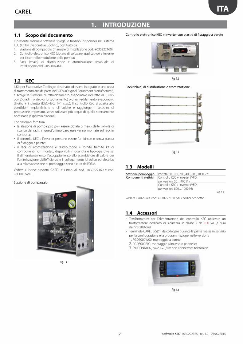
• CAREL pGD1 terminal to be connected during commissioning, for
confi guration and programming, in the following versions:
1. PGDE000W00, wall-mounting;
2. PGDE000F00, built-in or panel assembly;
3. S90CONN002, cable with telephone connector L=0.8 m.
Fig. 1.d
8
ENG
“software KEC” +030222165 - rel. 1.0 - 29/09/2015
• Temperature probe for CAREL ducts to be installed on the heat
exchanger outlet in the supply air stream, if control with fl ow-rate limit
is featured.
Fig. 1.e
P/N Description
DPDC110000Duct OUT probe: temp -10 to 60°C (0 to 1 Vdc, 4 to 20 mA),
humidity: 10 to 90 % RH (0 to 1 Vdc, 4 to 20 mA)
DPDC111000Duct OUT probe: temp -10 to 60°C (NTC), humidity: 10 to
90 % RH (0 to 1 Vdc, 4 to 20 mA)
DPDC112000Duct OUT probe: temp -10 to 60°C (0 to 10 Vdc), humidity:
10 to 90 % RH (0 to 10 Vdc)Tab. 1.b
• Baffl es for nozzles: these increase the angle of the spray cone and
increase the exchange surface for the fl ow of atomised water.
Fig. 1.f
1.5 Main featuresIn summary:
• Maximum operating pressure 14 bars;
• Request signal via serial from the air handling unit Master controller;
• Serial communication with the inverter so as to directly set the
parameters from the KEC controller and manage alarms;
• Flow-rate measuring device for precise control of the amount of water
sprayed and advanced no-water management;
• Availability of kits of distribution rack components, such as nozzles,
fi ttings and brackets for maximum fl exibility in developing the sprayed
water distribution system;
• Availability of software libraries for integration via serial (Modbus
protocol) of the controller with other controllers on the air handling
unit, in both CAREL 1Tool and c.suite environments.
9
ENG
“software KEC” +030222165 - rel. 1.0 - 29/09/2015
1.6 Architecture The KEC system receives the production request signal via serial from the
Master controller on the air handling unit and consequently activates the
pump, modulating the fl ow-rate. The pumping unit, together with the
fi ll and drain valves on the cabinet, controls the rack fi ll/drain valves. It
also controls the line drain valves (in.drain step1/2), useful for installations
where the pumping unit is lower than the distribution rack (*).
(*) in this case, opening of the drain valve on the pumping unit on its own
will not empty the water line.
12
3
4
6M 3~
7
15 14
12
11
13
8
10
1/2"
STEP 1 STEP 2
5
17
16
18
19
OUTSTEP 1
OUTSTEP 2
IN. DRAINSTEP 2
IN DRAINSTEP 1
DRAIN STEP 1
DRAIN STEP 2
9
C1
NO
1
NO
2
NO
4
C4 C7
NO
7
C7
NO
8
C8
NC8
G G0 U
1U
2
U3 G
ND
+VD
C
+Vte
rm
GN
D
+5 VR
EF
U4
GN
D
U5
GN
D
VG VG0
Y1 Y2 Y3 Y4 ID1
ID2
ID3
ID4
ID5
ID6
ID7
ID8
IDC1
J1 J24 J3 J4 J5
J14
J10
J13J12 J15
B M S card
J11 pLAN
4 3 2 1
C4
WATER SUPPLY
MASTER: AHU controller
pGD1 terminalfor commissioning
SLAVE: KEC controller
RACK: INSIDE AHU
PUMPSTATION
ELECTRONIC CONTROLLER+ INVERTER
1
2
3
6
11
12
5
14
10 913
15 1617
4
Q
24 Vac
230 Vac
2.5 A T
G G0
J1
100 VA Heat recoveryout temperature
J25 BMS2 J26 Fbus2
8
Fig. 1.g
1 Water fi lter 6 Pump 11 Mechanical thermostat 16 Rack drain solenoid valve step 12 Pressure reducer 7 Inverter 12 Temperature probe 17 Rack drain solenoid valve step 23 Low pressure gauge 8 Adjustable high pressure regulator 13 Pressure transducer 18 Line drain step 14 Fill solenoid valve 9 Fill solenoid valve step 1 14 High pressure gauge 19 Line drain step 25 Flow-rate measuring device 10 Fill solenoid valve step 2 15 Drain solenoid valve Q Electrical panel
Tab. 1.c
10
ENG
“software KEC” +030222165 - rel. 1.0 - 29/09/2015
1.7 Application diagrams
1.7.1 IECThe Master controller sends the modulating request signal - from 0 to
1000 - via the serial connection. The KEC starts production and decides
whether to activate one or two steps, based on the request signal.
The temperature probe needs to be installed at the heat exchanger
outlet for proportional or temperature-based fl ow control.
T1H1
T2H2
T3H3
T4H4
IEC: STEP1 + STEP2
KEC
MASTER: AHU controller
C1
NO
1
NO
2
NO
3
C1
C4
NO
4
NO
5
NO
6
C4
C7
NO
7
C7
NO
8
C8
NC
8
G G0
U1
U2
U3
GN
D
+V
DC
+Vt
erm
GN
D
+5
VREF
U4
GN
D
U5
GN
D
VG
VG
0
Y1 Y2 Y3 Y4 ID1
ID2
ID3
ID4
ID5
ID6
ID7
ID8
IDC
1
J1 J24 J2 J3 J4 J5
J10
S
Fig. 1.h
1.7.2 DEC + IECThe Master controller sends the modulating request signal - from 0 to
1000 - and the current operating mode (season) via the serial connection.
The KEC controller:
• in winter, activates DEC only;
• in summer, activates IEC only.
T1H1
T2H2
T3H3
T4H4
IEC: STEP 2
DEC: STEP 1
KEC
MASTER: AHU controller
C1
NO
1
NO
2
NO
3
C1
C4
NO
4
NO
5
NO
6
C4
C7
NO
7
C7
NO
8
C8
NC
8
G G0
U1
U2
U3
GN
D
+V
DC
+Vt
erm
GN
D
+5
VREF
U4
GN
D
U5
GN
D
VG
VG
0
Y1 Y2 Y3 Y4 ID1
ID2
ID3
ID4
ID5
ID6
ID7
ID8
IDC
1
J1 J24 J2 J3 J4 J5
J10
S
Fig. 1.i
Key
IEC Indirect evaporative cooling T3/H3 Air temperature/humidity at the heat exchanger outlet T2/H2 Return air temperature/humidityDEC Direct evaporative cooling S Temperature probe at the heat exchanger outletT1/H1 Air temperature/humidity outside T4/H4 Exhaust air temperature/humidity
11
ENG
“software KEC” +030222165 - rel. 1.0 - 29/09/2015
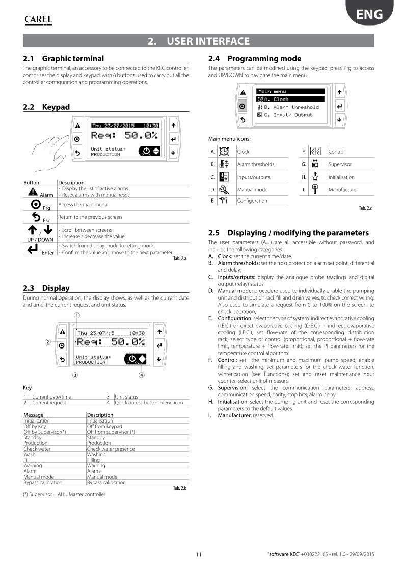
2. USER INTERFACE
2.1 Graphic terminalThe graphic terminal, an accessory to be connected to the KEC controller,
comprises the display and keypad, with 6 buttons used to carry out all the
controller confi guration and programming operations.
2.2 Keypad
Button Description
Alarm
• Display the list of active alarms
• Reset alarms with manual reset
PrgAccess the main menu
EscReturn to the previous screen
/
UP / DOWN
• Scroll between screens
• Increase / decrease the value
- Enter
• Switch from display mode to setting mode
• Confi rm the value and move to the next parameterTab. 2.a
2.3 DisplayDuring normal operation, the display shows, as well as the current date
and time, the current request and unit status.
1
2
3 4
Key
1 Current date/time 3 Unit status2 Current request 4 Quick access button menu icon
Message DescriptionInitialization InitialisationOff by Key Off from keypadOff by Supervisor(*) Off from supervisor (*)Standby StandbyProduction Production Check water Check water presenceWash WashingFill FillingWarning WarningAlarm AlarmManual mode Manual modeBypass calibration Bypass calibration
Tab. 2.b (*) Supervisor = AHU Master controller
2.4 Programming modeThe parameters can be modifi ed using the keypad: press Prg to access
and UP/DOWN to navigate the main menu.
Main menu icons:
A. Clock F. Control
B. Alarm thresholds G. Supervisor
C. Inputs/outputs H. Initialisation
D. Manual mode I. Manufacturer
E. Confi guration
Tab. 2.c
2.5 Displaying / modifying the parametersThe user parameters (A...I) are all accessible without password, and
include the following categories:
A. Clock: set the current time/date.
B. Alarm thresholds: set the frost protection alarm set point, diff erential
and delay;
C. Inputs/outputs: display the analogue probe readings and digital
output (relay) status.
D. Manual mode: procedure used to individually enable the pumping
unit and distribution rack fi ll and drain valves, to check correct wiring.
Also used to simulate a request from 0 to 100% on the screen, to
check operation;
E. Confi guration: select the type of system: indirect evaporative cooling
(I.E.C.) or direct evaporative cooling (D.E.C.) + indirect evaporative
cooling (I.E.C.); set fl ow-rate of the corresponding distribution
rack; select type of control (proportional, proportional + fl ow-rate
limit, temperature + fl ow-rate limit); set the PI parameters for the
temperature control algorithm.
F. Control: set the minimum and maximum pump speed, enable
fi lling and washing, set parameters for the check water function,
winterization (see Functions); set and reset maintenance hour
counter, select unit of measure.
G. Supervision: select the communication parameters: address,
communication speed, parity, stop bits, alarm delay.
H. Initialisation: select the pumping unit and reset the corresponding
parameters to the default values.
I. Manufacturer: reserved.
12
ENG
“software KEC” +030222165 - rel. 1.0 - 29/09/2015
2.6 Quick access menuThe quick access menu can be used to quickly access the unit information
and settings.
Procedure:
1. Press Esc one or more times to return to the standard display;
2. Press UP/DOWN until showing the icon required quick access menu
icon;
ICON
i
Set
Info On/Off Set point
Tab. 2.a
3. Press Enter to enter the menu, UP/DOWN to navigate, ESC to exit.
2.6.1 InfoThis comprises read-only screens displaying the main unit information:
• Current request and water fl ow-rate, pressure and temperature
C03 Digital inputsNO1 – Cabinet fi ll OP OP CL -NO2 – Cabinet drain OP OP CL -NO3 – Step 1 spray CL CL OP -NO4 – Step 2 spray CL CL OP -NO5 – Steps drain OP OP CL -NO6 – Steps in.drain OP OP CL -
Tab. 3.j
3.12 Manual mode
Note: manual mode can only be activated if the unit is in OFF from
the keypad.
At the end of the confi guration procedure, switch to manual mode so as
to check correct valve activation, inverter response and request.
Screen index Description on display Def Min Max UOMD01 Manual mode
Description ENG Def. UOM Min Max Notes Type R/W Modbus
Press UP/DOWN until the Info, Set and ON/OFF icons are shown on the main screen, then press Enter to access the quick access menuInfoQc01 Status - Pump Status - pumping unit
Request - kg/h - - Flow-rate: current request I RFlow rate - kg/h - - Current fl ow-rate I RPressure - bar - - Current pressure I RBypass temp. - °C - - Bypass temperature I R
Qc03 Working hoursPump 0 h Resettable pump counter I RUnit 0 h Total counter I R
Qc04 InfoUnit info:CAREL Industries S.p.A.
KEC - Confi gured for:- Pumping unit: selected during commissioning I RPump: - Kg/h Pumping unit nominal fl ow-rate I R -
Qc05 InfoSoftware info:Code: OSSTDmKECQVersion 1.0.017B Software versionOS 2.0.002 Operating system version I R
Set Set - PumpQb01 Min. fl ow (% nominal) 35.0 % Minimum pump speed I R/W -
Pressure thresholdHigh 14.0 bar Pressure threshold to activate 2nd step I R/W -Low 5.5 bar Pressure threshold to deactivate 2nd step I R/W -
Qb02 Set - RackMax production (%nom.) 100 % Maximum production expressed as % of rack fl ow-rate I R/W -Min production (%nom.) 0 % Minimum production expressed as % of rack fl ow-rate I R/W -
On/Off Qa01A. ClockA01 Date/Time change Current date/time
Format DD/MM/
YY
- DD/MM/YY MM/DD/YY Date format D R/W -
Date 01/01/00 gg/
mm/
aa
01/01/00 31/12/99 day/month/year I R/W -
Hour 00:00 hh:mm 00:00 23:59 hours: minutes I R/W -Day Saturday day of
week
Monday Sunday day of the week I R -
B. Alarm thresholdB01 Antifreeze Frost alarm
Set 5.0 °C -10.0 10.0 Set point I R/W -Hysteresis 2.0 °C -10.0 10.0 Diff erential I R/W -Delay 0 s 0 65535 Alarm delay I R/W -
C. Input/ OutputC01 Analog inputs (E05: Prop+Flow limit/Temp+Flow limit)
U1 - Heat recovery out temperature - °C - - I R -C02 Analog inputs
U3 - Bypass temperature - °C - - Water bypass temperature I R -U4 - Flow rate - Hz - - Flow-rate reading (Hz) I R -
- kg/h - - Flow-rate reading (kg/h) I R -U5 - Pressure - bar - - Pressure reading I R -
C03 Digital outputsNO1 - cabinet fi ll Open Open Closed Cabinet: fi ll valve D R -NO2 - cabinet drain Open Open Closed Cabinet: drain valve D R -
C04 NO3 - Step 1 spray Closed Closed Open Rack: step 1 D R -NO4 - Step 2 spray Closed Closed Open Rack: step 2 (E02 = 2 step) D R -
C05 NO5 - Steps drain Open Open Closed Rack: drain step 1,2 D R -NO6 - Steps in. drain Open Open Closed Rack: intermediate drain D R -
D. Manual mode Manual mode: can only be activated if unit OFF from keypad and no alarms
activeD01 Manual mode
Disabled ¦ Outputs ¦ Production
Disabled Disabled Production Outputs: activation of individual outputs
E04 Distribution systemPressure setpointHigh 14 bar 0 20 Pressure threshold to activate 2nd step I R/W -Low 5.5 bar 0 20 Pressure threshold to deactivate 2nd step I R/W -
E05 RegulationIEC Regulation mode:
Proportional ¦ Prop + Flow Limit ¦
Temp + Flow limit
Propor. Propor. Temp+Flow
Limit
I R/W -
DEC regulation mode Propor. I R -E06 Regulation (E05=Proportional+fl ow limit/Temp+fl ow limit) I R
Proportional requestON Threshold 10 % 0 100 % request-->prop. control ON I R/W -OFF Threshold 5 % 0 100 % request-->prop. control OFF I R/W -
Off set 0.0 °C -99.9 99.9 I R/W -Warning delay 0 s 0 600 I R/W -
E08 Regulation (E05=Temp+fl ow limit)Temperature regulationSetpoint 15.0 °C 0 100 I R/W -Diff erential 10.0 °C 0 100 I R/W -Prop. Band 5.0 °C 0 999.9 I R/W -Neutral zone 1.0 °C 0 999.9 I R/W -Integral time 300 s 0 999.9 I R/W -
F. RegulationF01 Pump settings
Prod. limitsNominal pump fl ow rate 100 kg/h 50 1000 I R/W -Min fl ow (% nom.) 35 % 0 100 I R/W -Max fl ow (% nom.) 100 % Min fl ow 100 I R/W -
F02 Pump settingsEnable fi ll
Yes ¦ No
Yes Yes No Yes ¦ No D R/W -
Wash mode
Drain only ¦ Daily ¦ Periodic
Periodic Periodic Daily I R/W -
F03 Pump settingsFill time 2 min 0 99 Filling duration I R/W -Wash time 2 min 0 99 Washing duration I R/W -Time 00:00 hh:mm 00:00 23:59Inactivity threshold 24 h 0 99 Inactivity threshold for activation of periodical washing I R/W -
F04 Water checkWater check time 15 s 0 999 Duration of water check I R/W -
F04 Missing water retry
timeout
10 min 0 999 Timeout (base time) for automatic water check I R/W -
F05 WinterizationWinterization timeout 5 min 0 180 Maximum of duration winterization procedure I R/W -Run winterization ? No - No Yes Request winterization activation D R/W -
F06 Hours counterMaintenance warning
threshold
1500 h 0 999999 System maintenance warning threshold I R/W -
Reset pump hours counter ? No - No Yes Reset pump hour counter D R/W -F07 Unit of measure
International (kg/°C) ¦
Imperial (lb/°F)
Internat. - - - - D R/W -
18
ENG
“software KEC” +030222165 - rel. 1.0 - 29/09/2015
Screen
index
Description ENG Def. UOM Min Max Notes Type R/W Modbus
G01 SupervisorProtocol Modbus Communication protocol D R -Address 1 1 254 I R/W -Baudrate (porta BMS2)
1200 ¦ 2400 ¦ 4800 ¦ 9600 ¦ 19200 ¦
38400
19200 1200 38400 I R/W -
Parity
None ¦ Odd ¦ Even
None None Even I R/W -
Stop bits 2 1 2 I R/W -G02 Supervisor
Supervisor offl ine alarm delay 5 s 0 99 See chap. Alarms I R/W -H. InitializationH01 Hydraulic group
NO MODEL (=before commissioning) ¦
KEC005DH*0 ¦ KEC005UH*0 ¦
KEC010DH*0 ¦ KEC010UH*0 ¦
KEC020DH*0 ¦ KEC020UH*0 ¦
KEC040DH*0 ¦ KEC040UH*0 ¦
KEC080DH*0 ¦ KEC080UH*0 ¦
KEC100DH*0 ¦ KEC100UH*0
NO
MODEL
I R/W -
Restore default ?
No ¦ Yes
No No Yes Return to default parameters corresponding to
selected pumping unit
D R/W -
I. ManufacturerRESERVED
Tab. 4.a
4.1 Variables accessible via serial
Note: in order to guarantee correct operation of the unit, do not
modify any variables NOT shown in the following table.
Modbus Type Modbus add. Parameter Description NotesCoil status 1 ResAl_SV Request alarm reset from supervisor Coil status 2 DefInstBySerial Request reset default values (manufacturer) via serial line Coil status 3 SVOnOff On Off from supervisory system Coil status 4 Season Current season IEC + IEC system onlyCoil status 5 ManWashReq Manual wash request Coil status 6 EnFill Enable fi lling Coil status 7 ManCabinet.SupplyW Manual mode: activate water fi ll Coil status 8 ManCabinet.Drain Manual mode: activate drain valve Coil status 9 ManStep1.Fill Manual mode: step 1 fi ll valve Coil status 10 ManStep1.Drain Manual mode: step 2 drain valve Coil status 11 ManStep1.InDrain Manual mode: step 1 drain valve line Coil status 12 ManStep2.Fill Manual mode: step 2 fi ll valve Coil status 13 ManStep2.Drain Manual mode: step 2 drain valve Coil status 14 ManStep2.InDrain Manual mode: step 2 line drain valve Coil status 15 ManSeason Manual mode: switch season on IEC + DEC system Coil status 16 PmpChng Request pump change Coil status 17 ResetPmpHrs Reset pump operating hour counter Coil status 18 ResetUnitHrs Reset unit operating hour counter Input status 1 Cabinet.SupplyW Fill valve status Input status 2 Cabinet.Drain Cabinet drain valve status Input status 3 Steps[1].Fill Status of step 1 fi ll valve Input status 4 Steps[1].Drain Status of step 1 drain valve Input status 5 Steps[1].InDrain Status of step 1 line drain valve Input status 6 Steps[2].Fill Status of step 2 fi ll valve Input status 7 Steps[2].Drain Status of step 2 drain valve Input status 8 Steps[2].InDrain Status of step 2 line drain valve Input status 9 CabinetSupplyW_Dout Status of digital output NO1 (water fi ll) Input status 10 CabinetDrain_Dout Status of digital output NO2 (drain pumping unit) Input status 11 Step1Fill_Dout Status of digital output NO3 (fi ll step 1) Input status 12 Step2Fill_Dout Status of digital output NO4 (fi ll step 2) Input status 13 StepsDrain_Dout Status of digital output NO5 (drain step 1+2) Input status 14 StepsInDrain_Dout Status of digital output NO6 (line drain step 1+2) Input status 15 Alrm_AFreeze.Active Alarm: frost protection Input status 16 Alrm_HiTemp.Active High bypass temperature alarm Input status 17 Alrm_Inv_General.Active General inverter alarm Input status 18 Alrm_Inv_DriveOverload.Active Inverter: drive overload alarm Input status 19 Alrm_Inv_HeatsinkOverH.Active Inverter: excess heat sink temperature alarm Input status 20 Alrm_Inv_MotorOverload.Active Inverter: motor overload alarm Input status 21 Alrm_Inv_Offl ine.Active Inverter: offl ine alarm Input status 22 Alrm_Inv_Overcurrent.Active Inverter: excess current alarm Input status 23 Alrm_Inv_Overtorque.Active Inverter: maximum torque exceeded alarm Input status 24 Alrm_Inv_Overvoltage.Active Inverter: overvoltage alarm
Input status 25 Warn_RecOutTPrb.ActiveWarning: exchanger outlet temperature probe faulty or
disconnected
Input status 26 Alrm_LoPress.Active Low pressure alarm output
Input status 27 Alrm_RecOutTPrb.ActiveAlarm: exchanger outlet temperature probe faulty or
disconnected
Input status 28 Alrm_NoModel.Active Incorrect pumping unit selection alarm Input status 29 Alrm_NoRack.Active Incorrect rack confi guration alarm Input status 30 Alrm_PressPrb.Active Pressure probe faulty or disconnected Input status 31 Alrm_SVOffl ine.Active Supervisor offl ine alarm
19
ENG
“software KEC” +030222165 - rel. 1.0 - 29/09/2015
Modbus Type Modbus add. Parameter Description NotesInput status 32 Alrm_TempPrb.Active Water temperature probe broken or disconnected Input status 33 Alrm_WMiss.Active No water alarm Input status 34 Warn_HiPress.Active Alarm: high outlet pressure Input status 35 Warn_HiTemp.Active Warning: high bypass temperature Input status 36 Warn_LowFlow.Active Alarm: low fl ow-rate (low production) Input status 37 Warn_Maint.Active Warning: maintenance request Input status 38 Warn_RetMem.Active Warning: non-volatile memory Input status 39 DefInst Default installation active Input status 40 isOff Unit off Input status 41 isOn Unit on Input status 42 KeybOnOff Unit off from keypad Input status 43 WaterFlowIsOK Water measured correctly by fl ow sensor Input status 44 CurrVer.EnBeta Software in BETA version Input status 45 ManModeAvaliable Manual mode can be activated Holding register 1 RTC.Day Internal clock: current day
Change to set internal clock
Holding register 2 RTC.DayOfWeek Internal clock: current day of the weekHolding register 3 RTC.Hour Internal clock: current hourHolding register 4 RTC.Minute Internal clock: current minutesHolding register 5 RTC.Month Internal clock: current monthHolding register 6 RTC.Year Internal clock: current yearHolding register 7 SerialReq Current request (0-1000 normalised to rack rating)
Holding register 9 InvManReqManual inverter speed request (0-100.0%, only if manual
mode active)
Holding register 10 MinPmpProd Minimum pump production (% of nominal fl ow) Holding register 11 MaxPmpProd Maximum pump production (% of nominal fl ow) Holding register 12 ZonesNumber Number of zones (1=IEC only, 2=IEC+DEC) Holding register 13 StepsNumber Number of rack steps (IEC mode / single zone only) Holding register 14 RackFlowRate_IEC IEC rack fl ow-rate Holding register 15 RackFlowRate_DEC DEC rack fl ow-rate Only used in 2 zone systemsHolding register 16 UnitRegulation.RegMode IEC control mode Holding register 17 UnitRegulation.TRegSetP Exchanger outlet temperature control: set point
Only available in IEC mode
Holding register 18 UnitRegulation.TRegPB Exchanger outlet temperature control: proportional bandHolding register 19 UniRegulation.TregThrON Exchanger outlet temperature control: ON diff erentialHolding register 20 UnitRegulation.TRegThrOFF Exchanger outlet temperature control: OFF diff erentialHolding register 21 UnitRegulation.TRegTi Exchanger outlet temperature control: integral timeHolding register 22 UnitRegulation.TregNZ Exchanger outlet temperature control: neutral zoneHolding register 23 UnitRegulation.MaxRackProd Maximum production Holding register 30 FillT Fill duration
Holding register 33 WashMode Type of wash0: drain only, 1: daily,
Holding register 61 WMissRetryTTime base to check water presence (in the event of no-
water alarm)
Holding register 67 UoM Current unit of measure 1: International; 2: Imperial
Holding register 68 RecOutPrbTyp_Msk Type of exchanger outlet temperature probe0: NTC; 1: 0-1V; 2: 0-10V;
3: 4-20mA; 4: 0-5VHolding register 69 RecOutTempCfg.AlrmDly Pressure probe: alarm delay Holding register 71 RecOutTempCfg.Ma Pressure probe: maximum value Holding register 72 RecOutTempCfg.Mi Pressure probe: minimum value Holding register 73 RecOutTempCfg.Off s Pressure probe: Off set Holding register 84 WintTOut Maximum winterization duration
Input register 1 Model Current model
0: No model, 1: KEC005DH*0;
2: KEC005UH*0; 3: KEC010DH*0;
4: KEC010UH*0; 5: KEC020DH*0;
6: KEC020UH*0; 7: KEC040DH*0;
8: KEC040UH*0; 9: KEC080DH*0;
10: KEC080UH*0; 11:
KEC100DH*0; 12: KEC100UH*0;Input register 2 WaterTemp Water temperature Input register 3 Pressure Current pressure Input register 4 FlowRate Current fl ow-rate (l/h) Input register 5 FlowRate_lm Current fl ow-rate (l/min) Input register 6 FlowRateFreq Current fl ow sensor frequency Input register 7 RecOutT Exchanger outlet temperature
8 InvSpeedReq Inverter: speed request (%) Input register 9 InvCurrFreq Inverter: current frequency applied Input register 10 InvCurrSpeed Inverter: current speed (%) Input register 11 FlowRequest Current request (l/h) Input register 12 OpenSteps No. of open steps Input register 13 CurrVer.X Current application: major release Input register 14 CurrVer.Y Current application: minor release Input register 15 CurrVer.Z Current application: build number Input register 16 OSVersion.X Operating system version: major release Input register 17 OSVersion.Y Operating system version: minor release Input register 18 OSVersion.Z Operating system version: build number
20
ENG
“software KEC” +030222165 - rel. 1.0 - 29/09/2015
Modbus Type Modbus add. Parameter Description Notes
Input register 19 MainStatus Current unit operating status
0: Start-up; 10: Initialisation;
20: Not used; 30: Wash; 40:
Fill; 50: Standby empty; 60:
Standby full; 70: Check water;
80: Production; 90: Slow
down; 100: Pre-wash; 105:
Winterization; 110: Alarm;
120: Bypass calibration fi ll;
130: Bypass calibration; 140:
Disabled
Input register 21 OnOff Status Current unit logical status