Manure Filtration Article 1 Technical Article August 2004 Membrane Filtration of Manure Wastewater A Comparison of Conventional Treatment Methods and VSEP, a Vibratory RO Membrane System. Greg Johnson a , Dr. Brad Culkin Ph.D. a , Larry Stowell a a New Logic Research, Incorporated 1295 67 th Street, Emeryville, CA 94608 Introduction If constructed and managed properly, the age-old lagoon method of manure handling is a reliable method of storing and treating livestock waste. Lagoon storage followed by sprayfield application on local farms has proven to be a very symbiotic and effective method throughout the ages. However, the recent trend in the hog production and the cattle industry is towards larger centralized operations housing thousands of animals in a confined area. The problem that arises is that the local biosphere used for dispersing the waste is fixed in size and has limited capacity to absorb manure fertilizer. Nutrient overload, pathogen release, excessive odor emissions, and tributary eutrophication are potential threats when operating a manure production facility at or near the limits of the land. Worries about liability and tightening regulations are driving changes in manure management practices. When you consider that for example there may be 4000 lagoons in North Carolina alone. The statistical probability of all 4000 lagoons being constructed and managed properly would be quite an accomplishment. Even if 100% successful in that endeavor, the liability is an overhang that can't be ignored. New manure management technologies are in a development phase at present, with few technologies at the commercialization stage. There are dozens of new technologies currently vying for acceptability and in the end one or a few will be proven out and be accepted as the norm. For many technologies, there is a lack of available information and data to complete a full analysis of their effectiveness. The evaluation and research process is ongoing worldwide as industry groups, universities, and individual livestock producers begin the task of rank ordering new methods for the treatment of livestock manure.
Transcript
Manure Filtration Article 1
Technical ArticleAugust 2004
Membrane Filtration of Manure Wastewater
A Comparison of Conventional Treatment Methodsand VSEP, a Vibratory RO Membrane System.
Greg Johnsona, Dr. Brad Culkin Ph.D. a, Larry Stowella
aNew Logic Research, Incorporated
1295 67th Street, Emeryville, CA 94608
Introduction
If constructed and managed properly, the age-old lagoon method of manure handling is areliable method of storing and treating livestock waste. Lagoon storage followed by sprayfieldapplication on local farms has proven to be a very symbiotic and effective method throughoutthe ages. However, the recent trend in the hog production and the cattle industry is towardslarger centralized operations housing thousands of animals in a confined area. The problem thatarises is that the local biosphere used for dispersing the waste is fixed in size and has limitedcapacity to absorb manure fertilizer. Nutrient overload, pathogen release, excessive odoremissions, and tributary eutrophication are potential threats when operating a manureproduction facility at or near the limits of the land.
Worries about liability and tightening regulations are driving changes in manure managementpractices. When you consider that for example there may be 4000 lagoons in North Carolinaalone. The statistical probability of all 4000 lagoons being constructed and managed properlywould be quite an accomplishment. Even if 100% successful in that endeavor, the liability is anoverhang that can't be ignored.
New manure management technologies are in a development phase at present, with fewtechnologies at the commercialization stage. There are dozens of new technologies currentlyvying for acceptability and in the end one or a few will be proven out and be accepted as thenorm. For many technologies, there is a lack of available information and data to complete afull analysis of their effectiveness. The evaluation and research process is ongoing worldwideas industry groups, universities, and individual livestock producers begin the task of rankordering new methods for the treatment of livestock manure.
Manure Filtration Article 2
VSEP Reverse Osmosis Treatment
New Logic Research has been installing membrane filtration systems since 1986, but has onlyrecently launched its agricultural waste system. The system, VSEP (vibratory shear enhancedprocess), is capable of filtration of practically any type of wastewater including landfill leachateand municipal sludge. Hundreds of industrial wastewater VSEP systems are installed aroundthe world. VSEP is a proven product that has been serving the industrial wastewater market formany years.
After realizing the benefits of VSEP when treating manure wastewater, New Logic installed itsfirst hog farm wastewater system in Korea in May of 2000. Since then, there have been threeother installations in Korea and three in Japan. New Logic is presently working on severalpotential manure system installations in North America and in Europe.
One of the advantages of VSEP is that it is a proven technology for which years of data exist.Rather than being an experimental technology with hidden problems or unknowns, VSEP has atrack record of performance and has demonstrated economical and reliable operation on a full-scale basis. One other benefit is that VSEP can be either used as the complete solution formanure treatment or can be used in conjunction with other technologies, as this article willdiscuss.
Standard Lagoon Methods
Most hog and cow farmers use anaerobic pondsto treat manure effluent. These lagoons can besimple and effective and if operated correctly cancontain odor problems. Anaerobic, (oxygenstarved), ponds tend to malfunction when theloading rate is too high, or when heavy organicloads are added infrequently. When an anaerobicpond gets out of balance due to overloading oruneven loading, odors can result.
Facultative lagoons are often used as secondarytreatment ponds in conjunction with anaerobicponds. A facultative pond has an aerobic,(oxygen rich), layer over an anaerobic layer. If a“facultative” lagoon doesn't have enough surfacearea or is not sufficiently oxygenated it willbehave like an anaerobic pond. This can beresolved by placing aerators on the lagoons andcreating a stratified lagoon. Stratified lagoons areanaerobic ponds with shallow mechanicalaerators installed to aerate the surface of thelagoon. Aeration is a proven odor controltechnology. However, it has high operating costs.
Manure Filtration Article 3
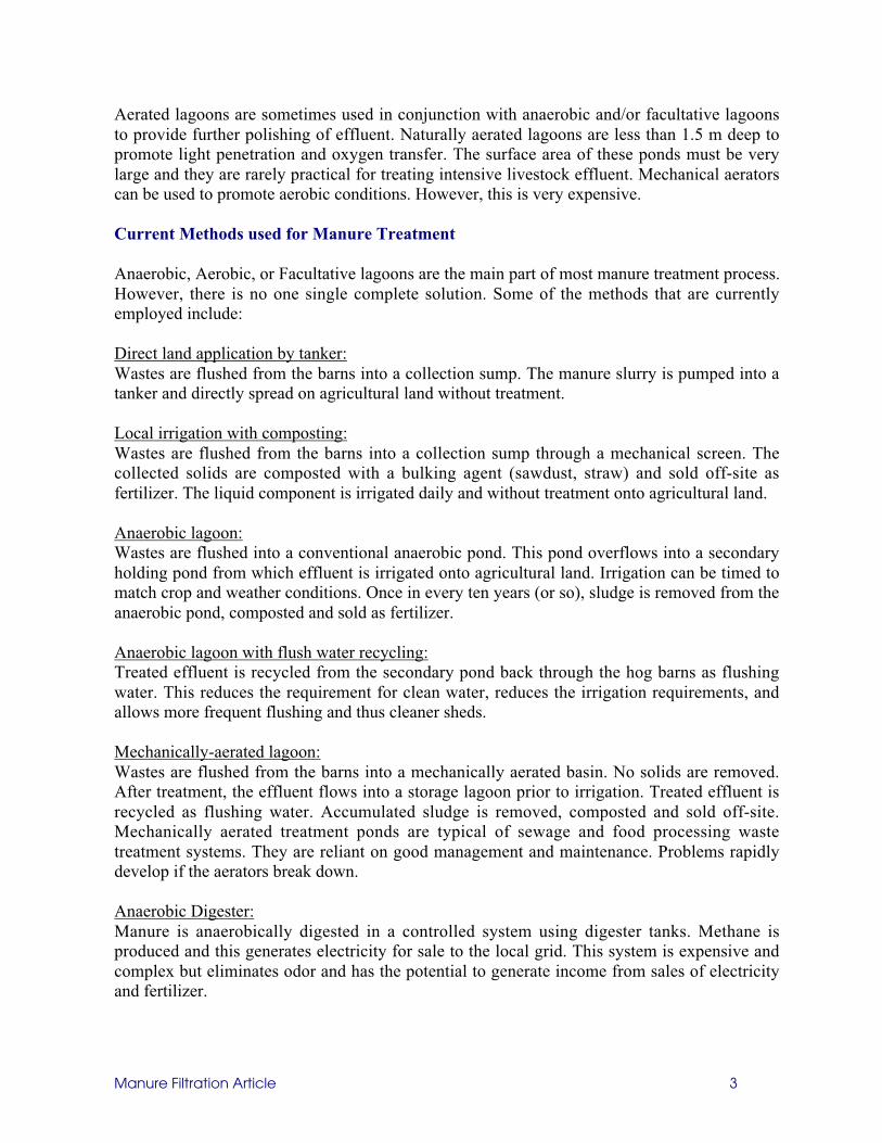
Aerated lagoons are sometimes used in conjunction with anaerobic and/or facultative lagoonsto provide further polishing of effluent. Naturally aerated lagoons are less than 1.5 m deep topromote light penetration and oxygen transfer. The surface area of these ponds must be verylarge and they are rarely practical for treating intensive livestock effluent. Mechanical aeratorscan be used to promote aerobic conditions. However, this is very expensive.
Current Methods used for Manure Treatment
Anaerobic, Aerobic, or Facultative lagoons are the main part of most manure treatment process.However, there is no one single complete solution. Some of the methods that are currentlyemployed include:
Direct land application by tanker:Wastes are flushed from the barns into a collection sump. The manure slurry is pumped into atanker and directly spread on agricultural land without treatment.
Local irrigation with composting:Wastes are flushed from the barns into a collection sump through a mechanical screen. Thecollected solids are composted with a bulking agent (sawdust, straw) and sold off-site asfertilizer. The liquid component is irrigated daily and without treatment onto agricultural land.
Anaerobic lagoon:Wastes are flushed into a conventional anaerobic pond. This pond overflows into a secondaryholding pond from which effluent is irrigated onto agricultural land. Irrigation can be timed tomatch crop and weather conditions. Once in every ten years (or so), sludge is removed from theanaerobic pond, composted and sold as fertilizer.
Anaerobic lagoon with flush water recycling:Treated effluent is recycled from the secondary pond back through the hog barns as flushingwater. This reduces the requirement for clean water, reduces the irrigation requirements, andallows more frequent flushing and thus cleaner sheds.
Mechanically-aerated lagoon:Wastes are flushed from the barns into a mechanically aerated basin. No solids are removed.After treatment, the effluent flows into a storage lagoon prior to irrigation. Treated effluent isrecycled as flushing water. Accumulated sludge is removed, composted and sold off-site.Mechanically aerated treatment ponds are typical of sewage and food processing wastetreatment systems. They are reliant on good management and maintenance. Problems rapidlydevelop if the aerators break down.
Anaerobic Digester:Manure is anaerobically digested in a controlled system using digester tanks. Methane isproduced and this generates electricity for sale to the local grid. This system is expensive andcomplex but eliminates odor and has the potential to generate income from sales of electricityand fertilizer.
Manure Filtration Article 4
Characteristics of Manure
Manure comprises both urine and feces. It consists of water, complex carbohydrates, andnutrients. Complex carbohydrates are broken down into simpler compounds such as carbondioxide and water during effluent treatment. Manure also contains large quantities of nitrogen,phosphorus and potassium, as well as minor nutrients, trace elements and salts. A range ofpathogens is also contained in pig manure.
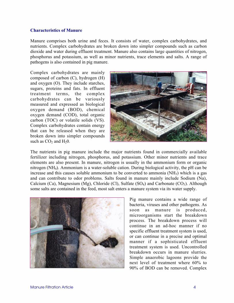
Complex carbohydrates are mainlycomposed of carbon (C), hydrogen (H)and oxygen (O). They include starches,sugars, proteins and fats. In effluenttreatment terms, the complexcarbohydrates can be variouslymeasured and expressed as biologicaloxygen demand (BOD), chemicaloxygen demand (COD), total organiccarbon (TOC) or volatile solids (VS).Complex carbohydrates contain energythat can be released when they arebroken down into simpler compoundssuch as CO2 and H20.
The nutrients in pig manure include the major nutrients found in commercially availablefertilizer including nitrogen, phosphorus, and potassium. Other minor nutrients and traceelements are also present. In manure, nitrogen is usually in the ammonium form or organicnitrogen (NH4). Ammonium is a water-soluble cation. During biological activity, the pH can beincrease and this causes soluble ammonium to be converted to ammonia (NH3) which is a gasand can contribute to odor problems. Salts found in manure mainly include Sodium (Na),Calcium (Ca), Magnesium (Mg), Chloride (Cl), Sulfate (SO4) and Carbonate (CO3). Althoughsome salts are contained in the feed, most salt enters a manure system via its water supply.
Pig manure contains a wide range ofbacteria, viruses and other pathogens. Assoon as manure is produced,microorganisms start the breakdownprocess. The breakdown process willcontinue in an ad-hoc manner if nospecific effluent treatment system is used,or can continue in a precise and optimalmanner if a sophisticated effluenttreatment system is used. Uncontrolledbreakdown occurs in manure slurries.Simple anaerobic lagoons provide thenext level of treatment where 60% to90% of BOD can be removed. Complex
Manure Filtration Article 5
treatment systems such as activated sludge units and sequence batch reactors can morecompletely breakdown BOD. If organic matter is broken down anaerobically, the end productsare mainly methane (CH4) and carbon dioxide (CO2) but other odorous gases are also produced.Most treatment systems allow the gases to escape to the atmosphere. However, methane is apotential energy source and is a greenhouse gas. Methane has about 20 times the globalwarming potential of carbon dioxide. Treatment systems can be designed to collect the methaneproduced by the anaerobic breakdown. If organic matter is broken down aerobically, more CO2
and less CH4 is produced.
Odor Creation
In most cases, odors from farm operations are created by incomplete anaerobic breakdown ofthe organic matter in manure. Anaerobic breakdown occurs in the absence of free oxygen anduses microorganisms that thrive in these conditions. It is a two-stage process. In the first stage,organic matter is converted to volatile fatty acids (VFA’s). In the second stages methane-forming bacteria convert these acids to methane (CH4) and carbon dioxide (CO2). The methane-forming bacteria can only survive in specific environments; for instance, they have a narrowpH range in which they can survive. Hence, incomplete anaerobic digestion may occur. Odorsemanate from the release of VFA’s and other compounds under these circumstances.
Simple Solids Removal Techniques
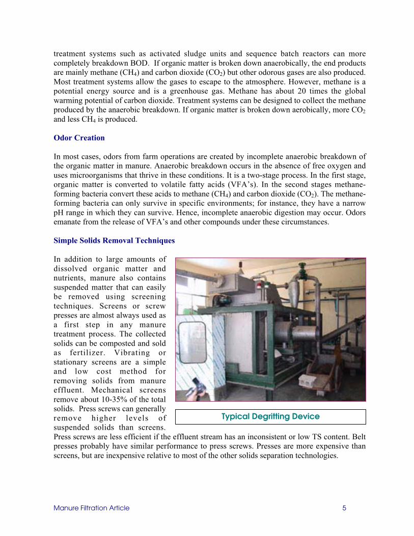
In addition to large amounts ofdissolved organic matter andnutrients, manure also containssuspended matter that can easilybe removed using screeningtechniques. Screens or screwpresses are almost always used asa first step in any manuretreatment process. The collectedsolids can be composted and soldas fertilizer. Vibrating orstationary screens are a simpleand low cost method forremoving solids from manureeffluent. Mechanical screensremove about 10-35% of the totalsolids. Press screws can generallyremove higher levels ofsuspended solids than screens.Press screws are less efficient if the effluent stream has an inconsistent or low TS content. Beltpresses probably have similar performance to press screws. Presses are more expensive thanscreens, but are inexpensive relative to most of the other solids separation technologies.
Typical Degritting Device
Manure Filtration Article 6
Alternative Advanced Technologies
There are a number of treatment systems out there for hog manure. Very few if any of these arecomplete solutions with a single piece of equipment. Most still require large lagoons orsimulate small-scale municipal wastewater treatment plants. One of the largest hog farms in thewestern United States actually produces as much waste as the entire county of Los Angeles. Allof these still leave the risk of pollution to the water supply by nitrates and pathogens.
There are several technology offerings, which are similar to standard municipal sludge wastetreatment plants. These will always have an image problem and require a very large footprint.Approval for these by the thousands will be problematic, as neighbor approval will be tepid. Atangential flow separator (TFS) is a sophisticated device that uses lime and polymer dosing andtangential flow to remove solids. It has very high capital, operating and maintenance costs. TFScan remove about 34% of TS and at least 90% of phosphorus. The separated solids have a TScontent ranging from about 6-40%. While the Tangential Flow Separator is effective at gettingPhosphorous, it is poor in removing TOC, Nitrogen, and COD. It also adds chlorides and Ironto the waste stream.
Typical Outdoor Aerobic Digester (Japan)
Manure Filtration Article 7
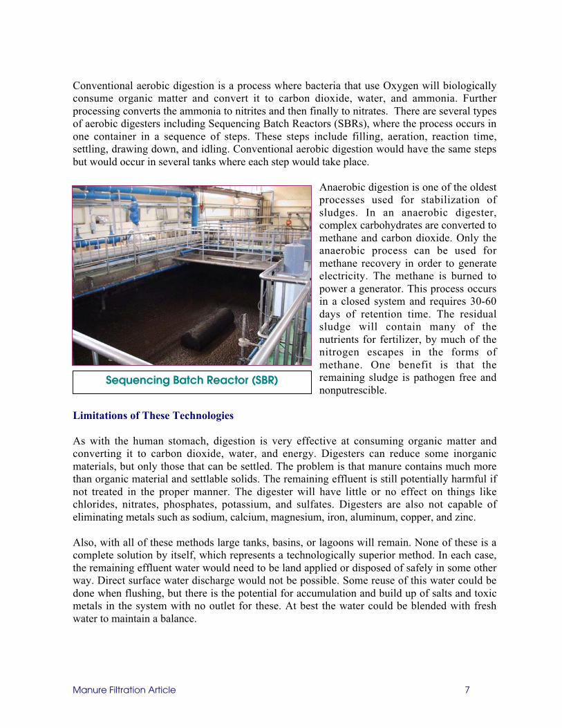
Conventional aerobic digestion is a process where bacteria that use Oxygen will biologicallyconsume organic matter and convert it to carbon dioxide, water, and ammonia. Furtherprocessing converts the ammonia to nitrites and then finally to nitrates. There are several typesof aerobic digesters including Sequencing Batch Reactors (SBRs), where the process occurs inone container in a sequence of steps. These steps include filling, aeration, reaction time,settling, drawing down, and idling. Conventional aerobic digestion would have the same stepsbut would occur in several tanks where each step would take place.
Anaerobic digestion is one of the oldestprocesses used for stabilization ofsludges. In an anaerobic digester,complex carbohydrates are converted tomethane and carbon dioxide. Only theanaerobic process can be used formethane recovery in order to generateelectricity. The methane is burned topower a generator. This process occursin a closed system and requires 30-60days of retention time. The residualsludge will contain many of thenutrients for fertilizer, by much of thenitrogen escapes in the forms ofmethane. One benefit is that theremaining sludge is pathogen free andnonputrescible.
Limitations of These Technologies
As with the human stomach, digestion is very effective at consuming organic matter andconverting it to carbon dioxide, water, and energy. Digesters can reduce some inorganicmaterials, but only those that can be settled. The problem is that manure contains much morethan organic material and settlable solids. The remaining effluent is still potentially harmful ifnot treated in the proper manner. The digester will have little or no effect on things likechlorides, nitrates, phosphates, potassium, and sulfates. Digesters are also not capable ofeliminating metals such as sodium, calcium, magnesium, iron, aluminum, copper, and zinc.
Also, with all of these methods large tanks, basins, or lagoons will remain. None of these is acomplete solution by itself, which represents a technologically superior method. In each case,the remaining effluent water would need to be land applied or disposed of safely in some otherway. Direct surface water discharge would not be possible. Some reuse of this water could bedone when flushing, but there is the potential for accumulation and build up of salts and toxicmetals in the system with no outlet for these. At best the water could be blended with freshwater to maintain a balance.
Sequencing Batch Reactor (SBR)
Manure Filtration Article 8
VSEP RO Filtration System
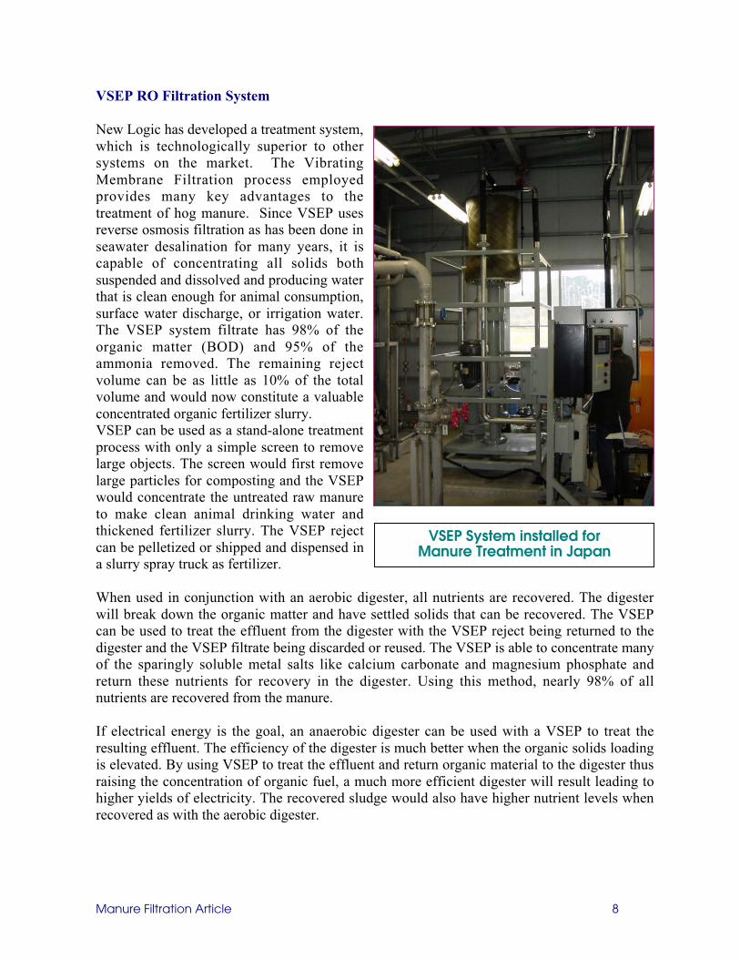
New Logic has developed a treatment system,which is technologically superior to othersystems on the market. The VibratingMembrane Filtration process employedprovides many key advantages to thetreatment of hog manure. Since VSEP usesreverse osmosis filtration as has been done inseawater desalination for many years, it iscapable of concentrating all solids bothsuspended and dissolved and producing waterthat is clean enough for animal consumption,surface water discharge, or irrigation water.The VSEP system filtrate has 98% of theorganic matter (BOD) and 95% of theammonia removed. The remaining rejectvolume can be as little as 10% of the totalvolume and would now constitute a valuableconcentrated organic fertilizer slurry.VSEP can be used as a stand-alone treatmentprocess with only a simple screen to removelarge objects. The screen would first removelarge particles for composting and the VSEPwould concentrate the untreated raw manureto make clean animal drinking water andthickened fertilizer slurry. The VSEP rejectcan be pelletized or shipped and dispensed ina slurry spray truck as fertilizer.
When used in conjunction with an aerobic digester, all nutrients are recovered. The digesterwill break down the organic matter and have settled solids that can be recovered. The VSEPcan be used to treat the effluent from the digester with the VSEP reject being returned to thedigester and the VSEP filtrate being discarded or reused. The VSEP is able to concentrate manyof the sparingly soluble metal salts like calcium carbonate and magnesium phosphate andreturn these nutrients for recovery in the digester. Using this method, nearly 98% of allnutrients are recovered from the manure.
If electrical energy is the goal, an anaerobic digester can be used with a VSEP to treat theresulting effluent. The efficiency of the digester is much better when the organic solids loadingis elevated. By using VSEP to treat the effluent and return organic material to the digester thusraising the concentration of organic fuel, a much more efficient digester will result leading tohigher yields of electricity. The recovered sludge would also have higher nutrient levels whenrecovered as with the aerobic digester.
VSEP System installed forManure Treatment in Japan
Manure Filtration Article 9
The three main uses of VSEP for manure treatment as shown above represent technologicallysuperior treatment methods. Maximum utilization and nutrient recovery is possible in eachcase. There is virtually no waste and all of the recovered materials, whether it is water,nutrients, or methane represent valuable products that can generate profit for the livestockfarmer. In addition to proven technical feasibility, VSEP, most importantly, is alsoeconomically viable and well within the reach of most hog farmers and dairy operations.
Membrane Introduction
Membrane separation technology has been around for many years. Initially, the use ofmembranes was isolated to a laboratory scale. However, improvements over the past twentyyears have made it possible to use membranes on an industrial level. A membrane is simply asynthetic barrier, which prevents the transport of certain components based on variouscharacteristics. Membranes are very diverse in their nature with the one unifying theme toseparate. Membranes can be either liquid or solid, homogeneous or heterogeneous and canrange in thickness. They can be manufactured to be electrically neutral, positive, negative orbipolar. These different characteristics enable membranes to perform many differentseparations from reverse osmosis to microfiltration.
There are four main categories of membrane filtration. These are determined by the Pore size orMolecular Weight Cut off:
Nanofiltration 0.001 to 0.01 micron 100 to 1000 daltonsUltrafiltration 0.01 to 0.1 micron 1000 to 500,000 daltonsMicrofiltration ≥ 0.1 micron ≥ 500,000 daltons
The first category of membranes is for Reverse Osmosis. These are the tightest membranes forseparating materials. They are generally rated on the % of salts that they can remove from afeed stream. However, they can also be specified by Molecular Weight cutoff. Usually, therejection of NaCl will be greater than 95% in order to be classed as an RO membrane. Themolecular weight cutoff is shown in the above table. An example of their use would be forfiltering seawater in order to remove the salt. They are also used to remove color, fragranceand flavor from water streams.
The advantage of the pure ionic separation of membranes has always held the interest of thosewishing to treat wastewater. In the past, the limitations of conventional spiral membranesystems have prevented widespread use because of rapid fouling due to colloidal scaleformation. Colloidal fouling obstructs the pores of the membrane and greatly reduces thethroughput and increases the frequency and amount of cleaning required. To combat thisproblem, elaborate pretreatment is used to prevent scale formation inside the membrane system.In addition spiral membrane companies have developed membranes that are extremelyhydrophilic so that organics are repelled. Even with these improvements, the limitations ofconventional spiral membranes have not allowed their widespread use in wastewater treatment.
Manure Filtration Article 10
SeismicMass
VSEP Advantages vs Conventional Membranes
A new membrane system know as VSEP, (vibratory shear enhanced process) employstorsional vibration of the membrane surface, which creates very high shearing energy at thesurface and near the pores. The result is that colloidal fouling and polarization of the membranedue to concentration of rejected materials are greatly reduced. Since colloidal scale fouling isavoided because of the vibration, the use of pretreatment to prevent scale formation is notrequired. In addition, the throughput rates of VSEP are 5-15 times higher in terms of GFD(gallons per square foot per day). The sinusoidal shear waves propagating from the membranesurface act to hold suspended particles above the membrane surface allowing free transport ofthe liquid media through the membrane. This accounts for the increased performance of VSEPmembrane filtration when compared to conventional spiral crossflow membrane filtration.
VSEP Technology Overview
Beyond the flow-induced shear of conventional crossflow filtration, VSEP can produceextremely high shear on the surface of the membrane because of the inherent oscillation at highfrequency. This accomplished by the torsional vibration of a disk plate in resonance within amass-spring-mass system. The membrane is attached to this plate and moves at an amplitudeof 1/2” to 1” peak-to-peak displacement. The frequency at which the system vibrates isbetween 50 and 55 Hz. Much as in a laundry machine, the fluid in the stack remains fairlymotionless creating a highly focused shear zone at the surface of the membrane. Retainedsolids at the membrane surface are removed by the shear allowing for higher operatingpressures and increased permeate rates. Feed pressure is provided by a pump, whichconsistently circulates new fluid to the filter.
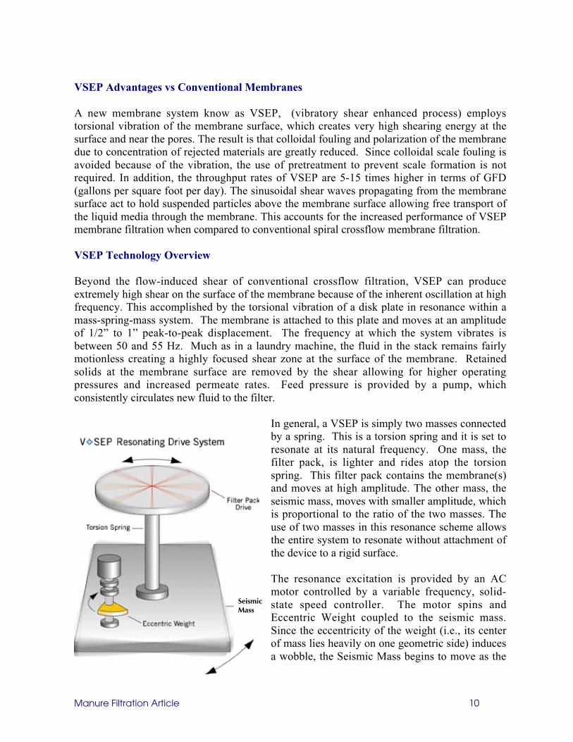
In general, a VSEP is simply two masses connectedby a spring. This is a torsion spring and it is set toresonate at its natural frequency. One mass, thefilter pack, is lighter and rides atop the torsionspring. This filter pack contains the membrane(s)and moves at high amplitude. The other mass, theseismic mass, moves with smaller amplitude, whichis proportional to the ratio of the two masses. Theuse of two masses in this resonance scheme allowsthe entire system to resonate without attachment ofthe device to a rigid surface.
The resonance excitation is provided by an ACmotor controlled by a variable frequency, solid-state speed controller. The motor spins andEccentric Weight coupled to the seismic mass.Since the eccentricity of the weight (i.e., its centerof mass lies heavily on one geometric side) inducesa wobble, the Seismic Mass begins to move as the
Manure Filtration Article 11
motor speed increases. This energy is transmitted up the torsion spring inducing the samewobble in the filter pack, however 180˚ out of phase. As the motor speed approaches theresonance frequency, the amplitude of the moving filter pack reaches a maximum, and greatermotor speed will only decrease the amplitude. VSEP is run under operating conditions belowthe maximum amplitude to reduce spring stress and ensure infinite spring life.
To allow for free movement of the system, VSEP is mounted on isolators. Solid piping to thefilter pack is attached to the Torsion Spring and is removed at the point of zero-amplitude(node). Flexible piping is used at the top of the filter pack. VSEP industrial and pilot systems(Series i and L/P can be operated in a single pass configuration, which makes them ideal forindustrial scale applications consisting of upwards of hundreds of gallons per minute. Duringsingle-pass operation, the material enters the top of the filter pack, and is progressivelydewatered by the membranes as the material passes down through the stack. This establishes aconcentration gradient, where the material at the top of the stack is most similar to the feedmaterial, and the material at the bottom of the stack is concentrated reject, having beendewatered as it passed through the filter pack. The concentrated material is essentiallyextruded from the bottom of the pack. The clear filtrate is removed through the center of thepack from a porous drainage cloth under each membrane sheet. The limit to concentrationvaries from feed material to feed material but essentially needs to remain flowing as a liquidwhich can be removed from to the outlet pipe.
Proposed VSEP Manure Process Description
VSEP can be used in many ways. Almost every VSEP manure installation thus far has beeninstalled in a slightly different configuration. Since VSEP is compact, modular, versatile andcan be used under very different operating conditions. It can handle very wide temperatureswings from 5ºC to 60ºC instantaneously. There is improved performance with increasedtemperatures, but VSEP can operate at any normal ambient temperature needed. It can alsotolerate large fluctuations in pH, solids loading, and changes in chemical composition of thewastewater. The VSEP works automatically and produces results immediately without reactiontime or waiting for biological activity to develop.
VSEP can be used in the following ways:
1. As a single treatment method with just a mechanical screen to make clean water for reuseand a concentrated nutrient slurry for composting, land application, or portable slurry foroff-site fertilization from a spray truck
2. As pre-treatment to either an aerobic or anaerobic digester. The clean water is producedahead of the digester for reuse. The concentrate from the VSEP is then sent to the digesterat a greatly reduced volume. This means a smaller digester system that is working on moreconcentrated material thus improving efficiency.
3. As post-treatment for a digester to treat the effluent produced. VSEP polishes the water tomake it suitable for reuse or discharge. The reject from the VSEP can be either returned tothe digester or blended with digester sludge or blended with screen reject composting.
Manure Filtration Article 12
VSEP Only Manure Treatment
The only pre-treatment required for the VSEP is a coarse mechanical screen to prevent beachsand sized particles from entering the system. It is not necessary to completely removesuspended solids, only the ones large enough to act as projectiles and possibly do damage to themembrane. Normally, 60 to 100 mesh screen size is sufficient.
This proposed process would take effluent from the settling basin or other primary holdingtank, which has passed through a wire screen, and then filter this liquid using a reverse osmosismembrane. The filtrate from this would be sent to water storage holding structure of some kind.This clean water then becomes available for animal drinking water, flush water, or forirrigation. The concentrated reject from the filtration system would be returned to a batchprocess feed tank. This “Batch Concentration” process would continue until the % solids in thetank reaches 12% solids or greater. At that time the contents could be hauled and sold as slurryfertilizer. The clean filtrate from the water storage holding basin, now like a duck pond couldbe used for recharging of the trenches in the barn or for cooling cell operations. The trencheswould continue to function as they do now, only with cleaner water as the charge.
There is a trade off between high % solidsand throughput of clean filtrate. Higher %solids could be reached but at the expenseof reduced throughput. The same is true inthe opposite. More throughput could behandled but at the expense of lower %solids at the end of a batch concentrationrun. The optimum % solids andthroughput have been determined to beapproximately 12% solids, 80% recoveryof filtrate, and 20 gpm per module. Toillustrate the relationship betweenconcentration and throughput, the VSEPcan also produce 20% solids in theconcentrate, but only at a rate of 10 gpmper module. Or, conversely, VSEP couldproduce 5% solids in the concentrate at aflow rate of 25 gpm. These numbers areapproximately and may vary depending onthe type of farm and the ambienttemperature, but they show thecorrespondence of concentration andthroughput. Modules are units within thesystem and the total system can be sizedfor any total flow rate. VSEP System installed for Hog
Manure Treatment in Korea
Manure Filtration Article 13
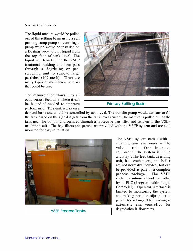
System Components
The liquid manure would be pulledout of the settling basin using a selfpriming sump pump or centrifugalpump which would be installed ona floating buoy to pull liquid fromthe top foot of tank level. Theliquid will transfer into the VSEPtreatment building and then passthrough a degritting or pre-screening unit to remove largeparticles, (100 mesh). There aremany types of mechanical screensthat could be used.
The manure then flows into anequalization feed tank where it canbe heated if needed to improveperformance. This tank works on ademand basis and would be controlled by tank level. The transfer pump would activate to fillthe tank based on the signal it gets from the tank level sensor. The manure is pulled out of thetank near the bottom and pumped through a protective bag filter and sent on to the VSEPmachine itself. The bag filters and pumps are provided with the VSEP system and are skidmounted for easy installation.
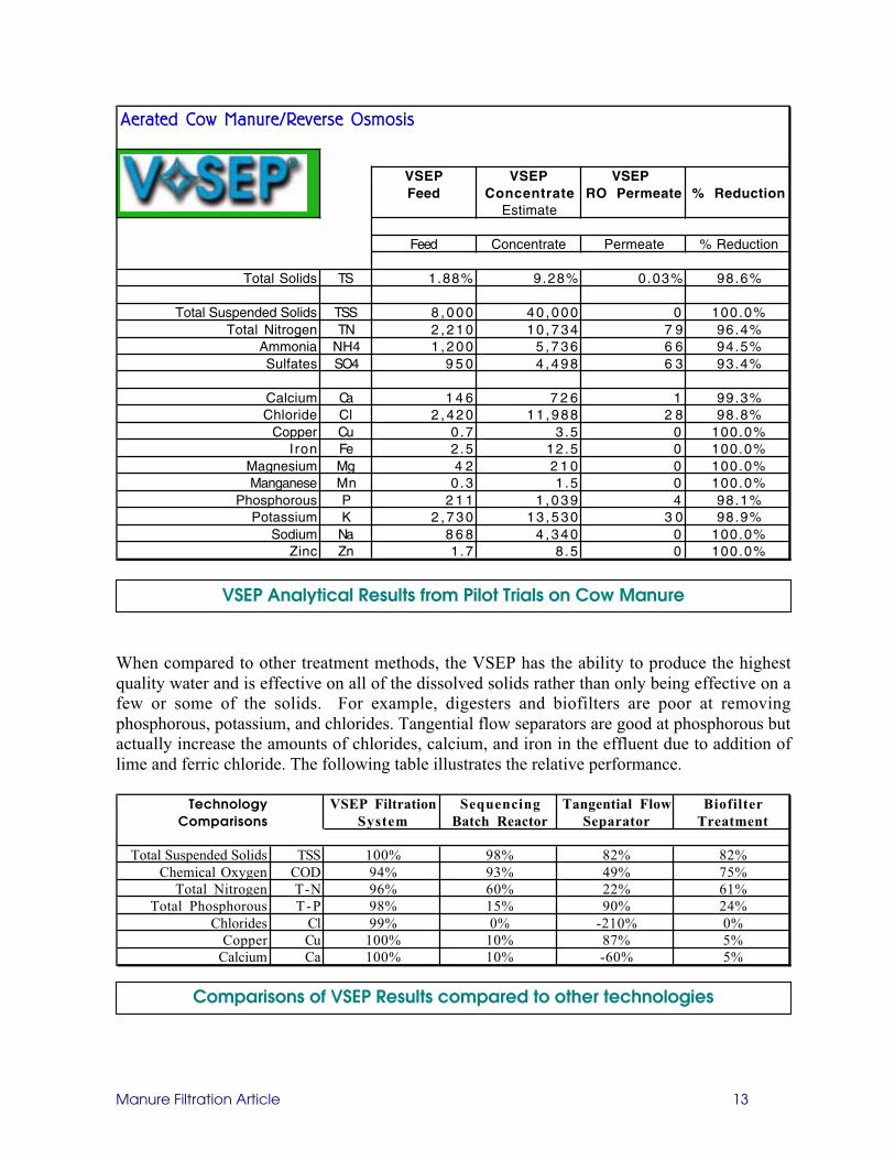
The VSEP system comes with acleaning tank and many of thevalves and other interfaceequipment. The system is “Plugand Play”. The feed tank, degrittingunit, heat exchangers, and boilerare not normally included, but canbe provided as part of a completeprocess package. The VSEPsystem is automated and controlledby a PLC (Programmable LogicController). Operator interface islimited to monitoring the systemand making periodic adjustment toparameter settings. The cleaning isautomatic and controlled fordegradation in flow rates.
Primary Settling Basin
VSEP Process Tanks
Manure Filtration Article 13
VSEP as Pre-treatment to a Digester
VSEP can be used to pre-concentrate or thicken the manure prior to aerobic or anaerobicdigestion. The main benefit to this is that the digester size and expense can be cut significantly.VSEP could be used to remove 50-85% of the liquid volume as clean water reducing the size ofthe needed digester by a proportional amount. Many digesters will be more efficient when thesolids level is elevated. For this scenario, the VSEP would be configured as shown in the VSEPonly scenario. In this case though, very high recovery would not be as critical and the VSEPwould be used primarily to take the load off the digester. The VSEP could also be used as aredundant bypass should the digester require reaction time or other downtime maintenance.Again, the VSEP would take liquid manure out of the settling basing that has been pre-screenedand then filter is using reverse osmosis. As before the clean water will be diverted to a waterstorage holding tank or basin for reuse. The thickened concentrate from the VSEP would besent to the digester for processing.
The benefit to this over the VSEP alone scenario is that the sludge is stabilized in the digester.After being digested, it will not putrefy since all of the organic material has been converted tostable compounds. It can be pelletized, or dried to make bagged fertilizer and will remainstable. In the digestion process pathogens are also destroyed. The Volatile Fatty Acids havebeen broken down to carbon dioxide and water and the ammonia has been converted to nitratesso most of the odor associated with manure is neutralized.
VSEP Post-Digester
This is the most common method of using the VSEP. Our first installation in Korea has asequencing batch reactor (SBR) in front of the VSEP reverse osmosis filtration system. In thesecases the purpose of the VSEP is to produce clean water from the digester effluent that can bedischarged or reused and to capture any remaining nutrients in the digester effluent that may bedissolved or not captured by the digester. In the case above where the VSEP is used ahead ofthe digester to volume reduce the wastewater, the concentrate has one destination which is thedigester. In the case of post-treatment with VSEP, there would be several possible destinationsfor the VSEP concentrate. It can be returned to the digester for additional biologicaldegradation, it can be blended with the sludge removed from the digester, or it can be blendedwith the screen rejects for composting.
A mechanical screen, screw press, or centrifuge is normally used ahead of the digester toremove the large solids that would take a long time to deteriorate in the digester. After thedegritting and screening step, an air stripper can be used to remove some of the ammonia andVFAs to make it more comfortable for the workers operating the digester. SBRs are operatedindoors so odor from manure can be a problem even though SBRs are aerobic. Also, sulfide gascan be a health concern and is also removed via air stripping. Outdoor conventional digestersmay not need air stripping. After degritting, the manure is feed to the digester in a batchmethod. The digester is first filled and then allowed to react and then settle. After settling andsufficient time for digestion, the water is drawn down and this effluent is then sent to the VSEPequalization tank. VSEP can be used on demand and can start and stop based on tank level.VSEP then filters the effluent to create clean water for discharge or reuse.
Manure Filtration Article 13
VSEP Performance
New Logic has many installed manure applications and so the performance results of the VSEPare quite well known. There may however, be slight variations from location to location. Pilottesting is always a good idea to confirm estimated results. There can be many differences fromfarm to farm. Cow manure is different than hog manure and there are even different kinds ofhog manure depending on whether the manure is from sows or feeder pigs. Cow manuretypically has higher suspended solids and lower dissolved solids than hog manure. Each animalalso processes nutrients and minerals differently. Also, the nutrients, salts, and minerals thatend up in the manure are a function of the water used and the feed material that is given to theanimals.
In general, the VSEP is able to produce slightly higher throughputs on digester effluent than onraw manure. This is not true in all case though, but on average is true. The following tableillustrates performance throughput on several manure scenarios. Membranes are rated based ontheir throughput per square foot of membrane. The value given to the is GFD which stands forgallons of permeate produced per square foot of membrane per day.
Averages Single Stage Reverse Osmosis
Untreated Raw Aerobic Digester Untreated Raw Aerobic DigesterHog Manure Hog Manure Cow Manure Cow Manure
Temperature 25ºC 25ºC 25ºC 25ºCMembrane Used LFC 1 LFC 1 LFC 1 LFC 1
Pressure Used 575 psi 600 psi 600 psi 500 psi
Ambient temperature and pH also can affect the VSEP system performance. With so manyvariables that can affect the make up of the manure, it's hard to generalize about the VSEPperformance, but some estimates can be made. The following table shows the results from arecent trial conducted on cow manure after it had been treated with an aerobic digester.
Exit Valve
P
CONCENTRATE(SLUDGE)
CLEARPERMEATE
1
2
3
V✧SEP
Valve Switch andTiming Control Circuitry
FEED SLURRY
Manure Filtration Article 13
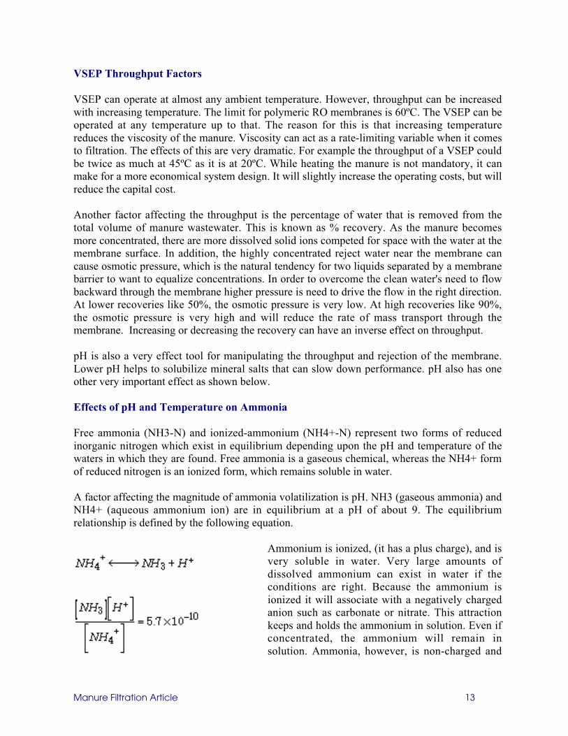
When compared to other treatment methods, the VSEP has the ability to produce the highestquality water and is effective on all of the dissolved solids rather than only being effective on afew or some of the solids. For example, digesters and biofilters are poor at removingphosphorous, potassium, and chlorides. Tangential flow separators are good at phosphorous butactually increase the amounts of chlorides, calcium, and iron in the effluent due to addition oflime and ferric chloride. The following table illustrates the relative performance.
VSEP Analytical Results from Pilot Trials on Cow Manure
Comparisons of VSEP Results compared to other technologies
VSEP can operate at almost any ambient temperature. However, throughput can be increasedwith increasing temperature. The limit for polymeric RO membranes is 60ºC. The VSEP can beoperated at any temperature up to that. The reason for this is that increasing temperaturereduces the viscosity of the manure. Viscosity can act as a rate-limiting variable when it comesto filtration. The effects of this are very dramatic. For example the throughput of a VSEP couldbe twice as much at 45ºC as it is at 20ºC. While heating the manure is not mandatory, it canmake for a more economical system design. It will slightly increase the operating costs, but willreduce the capital cost.
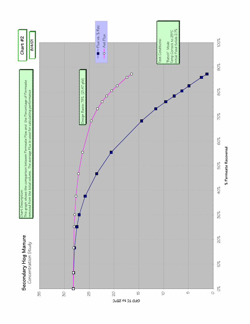
Another factor affecting the throughput is the percentage of water that is removed from thetotal volume of manure wastewater. This is known as % recovery. As the manure becomesmore concentrated, there are more dissolved solid ions competed for space with the water at themembrane surface. In addition, the highly concentrated reject water near the membrane cancause osmotic pressure, which is the natural tendency for two liquids separated by a membranebarrier to want to equalize concentrations. In order to overcome the clean water's need to flowbackward through the membrane higher pressure is need to drive the flow in the right direction.At lower recoveries like 50%, the osmotic pressure is very low. At high recoveries like 90%,the osmotic pressure is very high and will reduce the rate of mass transport through themembrane. Increasing or decreasing the recovery can have an inverse effect on throughput.
pH is also a very effect tool for manipulating the throughput and rejection of the membrane.Lower pH helps to solubilize mineral salts that can slow down performance. pH also has oneother very important effect as shown below.
Effects of pH and Temperature on Ammonia
Free ammonia (NH3-N) and ionized-ammonium (NH4+-N) represent two forms of reducedinorganic nitrogen which exist in equilibrium depending upon the pH and temperature of thewaters in which they are found. Free ammonia is a gaseous chemical, whereas the NH4+ formof reduced nitrogen is an ionized form, which remains soluble in water.
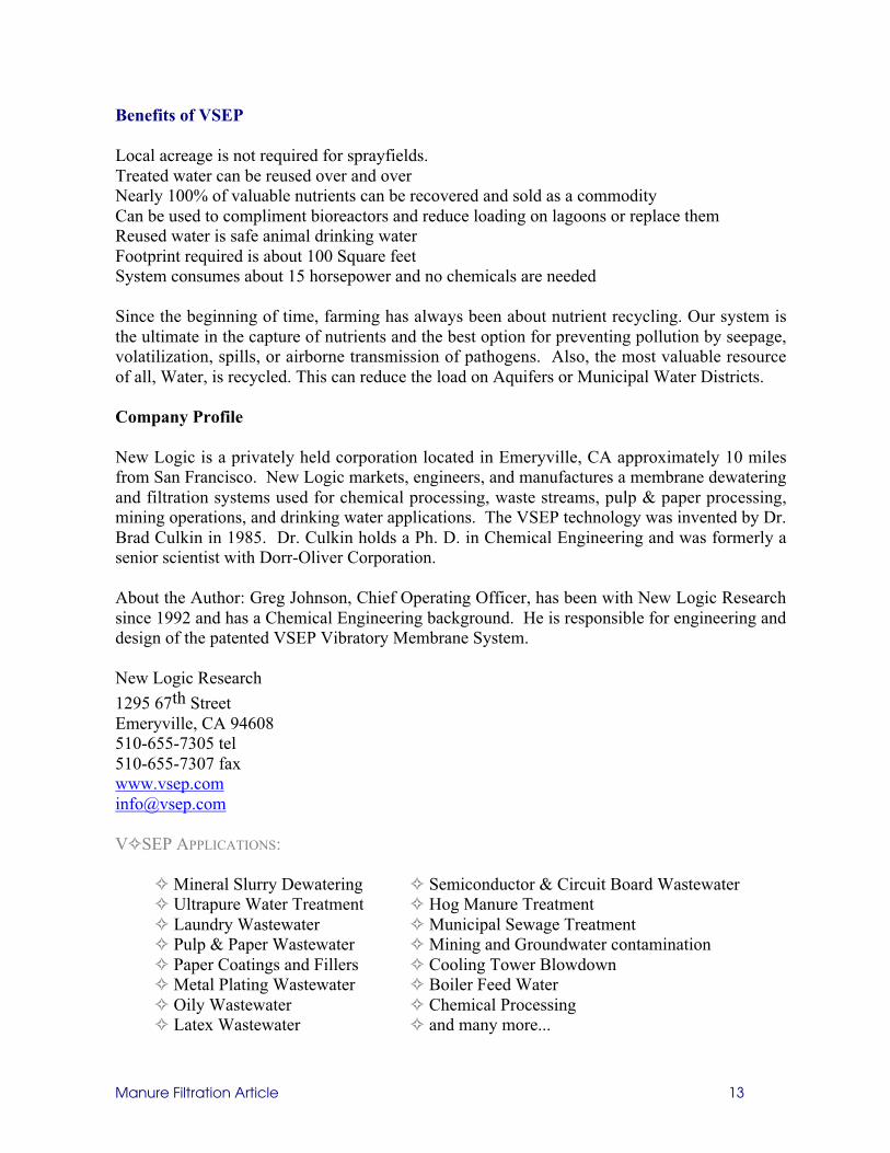
A factor affecting the magnitude of ammonia volatilization is pH. NH3 (gaseous ammonia) andNH4+ (aqueous ammonium ion) are in equilibrium at a pH of about 9. The equilibriumrelationship is defined by the following equation.
Ammonium is ionized, (it has a plus charge), and isvery soluble in water. Very large amounts ofdissolved ammonium can exist in water if theconditions are right. Because the ammonium isionized it will associate with a negatively chargedanion such as carbonate or nitrate. This attractionkeeps and holds the ammonium in solution. Even ifconcentrated, the ammonium will remain insolution. Ammonia, however, is non-charged and
Manure Filtration Article 13
has a limited solubility in water as a gas. If the pH or temperature changes or the solution isconcentrated shifting the concentrations of ammonia past its solubility, then it will evolve as agas and leave the liquid rather than convert to ammonium.
Ammonia and ammonium exist in equilibrium depending on the pH. A solution pH above 7begins to reduce the concentration of the ammonium ion, since the equilibrium between themono-valent ammonium ion and the uncharged ammonia molecule shifts toward ammonia asthe pH approaches the basic range. Since the ammonia gas has a limited solubility, raising pHwill shift ammonium to ammonia and in doing so drive ammonia out of solution as an evolvedgas, which leaves the system to the atmosphere. The graph below shows the relationshipbetween ammonium and ammonia concentrations with regard to pH.
As you can see, at pH 6, nearly all ofthe Ammonical Nitrogen is in the formof the ionized ammonium, which willbe soluble in water in high quantities.At a pH of 11, there is no ammoniumand any ammonical nitrogen presentwould be in the form of ammonia,Since this has a limited solubility, anyexcess would evolve and leave theliquid as a gas. If the objective were tokeep the ammonical nitrogen in thesystem, operation at pH 7 or less wouldbe required.
When it comes to ammonia rejection using RO membranes, with little ionic charge to enhancerejection, the very small non-charged ammonia molecule readily permeates RO membranes.When pH is raised from 5.0 to 8.5 the ammonia rejection of an RO system drops from 95% to62%. The fact that ammonium has a plus charge makes it less likely to diffuse through an ROmembrane. Since ammonia has no charge and is very small, it has an easier time diffusingthrough the membrane.
Therefore, operating an RO system at a pH of less than 7 will result in the bestrejection/concentration of ammonical nitrogen. If the objective was to get rid of ammonicalnitrogen, the pH should be raised to pH 11 and then the solution should be sent through an airstripper to evolve the ammonia gas. Then the pH can be dropped to 6 and filtered using an ROmembrane. This will result in very dramatic reductions in ammonical nitrogen in the resultingfiltrate.
Temperature also affects solubility of ammonia/ammonium, but to a lesser degree. As withmost gases, raising the temperature makes ammonia less soluble. If the objective is to recovernitrogen for its nutrient value, the ammonia must be kept as ammonium as much as possible.To do this, the pH of the sample should be kept at pH 6
Manure Filtration Article 13
Benefits of VSEP
Local acreage is not required for sprayfields.Treated water can be reused over and overNearly 100% of valuable nutrients can be recovered and sold as a commodityCan be used to compliment bioreactors and reduce loading on lagoons or replace themReused water is safe animal drinking waterFootprint required is about 100 Square feetSystem consumes about 15 horsepower and no chemicals are needed
Since the beginning of time, farming has always been about nutrient recycling. Our system isthe ultimate in the capture of nutrients and the best option for preventing pollution by seepage,volatilization, spills, or airborne transmission of pathogens. Also, the most valuable resourceof all, Water, is recycled. This can reduce the load on Aquifers or Municipal Water Districts.
Company Profile
New Logic is a privately held corporation located in Emeryville, CA approximately 10 milesfrom San Francisco. New Logic markets, engineers, and manufactures a membrane dewateringand filtration systems used for chemical processing, waste streams, pulp & paper processing,mining operations, and drinking water applications. The VSEP technology was invented by Dr.Brad Culkin in 1985. Dr. Culkin holds a Ph. D. in Chemical Engineering and was formerly asenior scientist with Dorr-Oliver Corporation.
About the Author: Greg Johnson, Chief Operating Officer, has been with New Logic Researchsince 1992 and has a Chemical Engineering background. He is responsible for engineering anddesign of the patented VSEP Vibratory Membrane System.
New Logic Research
1295 67th StreetEmeryville, CA 94608510-655-7305 tel510-655-7307 [email protected]
V✧SEP APPLICATIONS:
✧ Mineral Slurry Dewatering ✧ Semiconductor & Circuit Board Wastewater✧ Ultrapure Water Treatment ✧ Hog Manure Treatment✧ Laundry Wastewater ✧ Municipal Sewage Treatment✧ Pulp & Paper Wastewater ✧ Mining and Groundwater contamination✧ Paper Coatings and Fillers ✧ Cooling Tower Blowdown✧ Metal Plating Wastewater ✧ Boiler Feed Water✧ Oily Wastewater ✧ Chemical Processing✧ Latex Wastewater ✧ and many more...
Manure Filtration Article 13
BIBLIOGRAPHY
The following Publications or Articles were used for preparation of this study:
American Society of Civil Engineers, 1997, Water Treatment Plant Design 3rd Edition, New York:McGraw-Hill, 806 p.
J. Morris, R. Fleming, M. MacAlpine, Pigs Accept Drinking Separated Water from Liquid Manure,University of Guelph, Ridgetown College Research Note, 2004
G. Johnson, VSEP Industrial Strength Filtration, Chemical Processing Magazine Article, 2003
G. Johnson, Kinetics of Mineral Scale Membrane Fouling, Desalination Article, 2003
New Logic Research, VSEP Case Study, Treatment of Hog Farm Liquid Manure Wastewater, 2001
R. Fleming, M. MacAlpine, Evaluation of Mechanical Liquid/Solid Manure Separators, University ofGuelph, Ridgetown College Research prepared for Ontario Pork, 2003
K. Zering, How to Select an Alternative Manure Treatment System, North Carolina Pork ConferencePaper, 2000
L. Jackson, Water Quality, University of Northern Iowa Article, 2001
J.G. Pieters, G. G. Neukermans, M. Colanbeen, Farm-Scale Filtration of Sow Slurry, University ofGhent Article, 1999
E. Warnemuende, R. Kanwar, The Effect of Swine Manure Application on Bacterial Quality ofLeachate from Intact Soil Columns. 2001
United States Environmental Protection Agency (EPA), 2003, 40 CFR 141 & 143, National PrimaryDrinking Water Standards, 5 p.
United States Environmental Protection Agency (EPA), 2003, 40 CFR 141 & 143, National SecondaryDrinking Water Standards, 5 p.
United States Environmental Protection Agency (EPA), Environmental Regulation & Location of HogProduction, Agricultural Outlook Newsletter, 2000
Manure Filtration Article 13
ATTACHMENTS
Figures
Figure 1. VSEP Only Process Flow DiagramFigure 2. Anaerobic Fixed Film Digester followed by VSEP Process Flow DiagramFigure 3. Anaerobic Digester w/ Methane Recovery followed by VSEP Process Flow DiagramFigure 4. VSEP prior to Aerobic Digestion Process Flow DiagramFigure 5. Ultrafiltration Block DiagramFigure 6. RO VSEP after Anaerobic Digestion Block DiagramFigure 7. RO VSEP after SBR Aerobic Digestion Block DiagramFigure 8. Nutrient Mass Balance
Images
Image #1 Korean Installation Images page oneImage #2 Korean Installation Images page two
Charts
Chart #1 % Solids vs. % RecoveryChart #2 Permeate Flux vs. % RecoveryChart #3 Permeate Conductivity vs. % RecoveryChart #4 Permeate Flux vs. Process TemperatureChart #5 Permeate Flux vs. TimeChart #6 UF, NF, & RO Flux ComparisonsChart #7 Permeate Flux vs. Pressure
Raw
Man
ure
60,0
00 G
PD6-
7% T
otal
Sol
ids.
Scre
w P
ress
Filtr
ate
~ 51
,000
GPD
4-5%
Tot
al S
olid
sV
SEP
Con
cent
rate
~ 10
,200
GPD
Gal
s12
-15%
Tot
al S
olid
s
Lan
d A
pplic
atio
n
Bed
ding
Opt
ions
Pres
sed
Solid
s 40
-45%
Man
ure
from
Bar
ns
2000
-Hea
d D
airy
Liq
uid-
Man
ure
Tre
atm
ent
Syst
em
Aer
obic
Com
post
ing
Stor
age
Sale
Cle
ar-W
ater
Lag
oon
~40,
800
GPD
Scre
w P
ress
/VSE
PN
ew L
ogic
Res
earc
h, I
nc.
1295
67th
Str
eet,
Em
eryv
ille,
CA
946
08
A
tlan
ta O
ffic
e :
770
-421
-920
5
Flo
w S
chem
atic
#1
VSE
P M
embr
ane
Filt
rati
on
Raw
Man
ure
EQ
Tan
kFr
om 5
Bar
nsM
ixed
and
Cho
pped
Scre
w P
ress
VSE
PFe
ed T
ank
VSE
P
VSE
PC
once
ntra
te
Man
ure
from
5 B
arns
Ana
erob
ic F
ixed
Film
Dig
este
r/V
SEP
Hog
Far
mL
iqui
d M
anur
eT
reat
men
t Sy
stem
Ana
erob
icFi
xed
Film
Dig
este
r
Com
post
Pad
&St
orag
e
Cle
ar W
ater
“D
ugou
t” L
agoo
n
New
Log
ic R
esea
rch,
Inc
.12
95 6
7th S
tree
t, E
mer
yvill
e, C
A 9
4608
Atl
anta
Off
ice
: 7
70-4
21-9
205
Flo
w S
chem
atic
#2
VSE
P M
embr
ane
Filt
rati
on
Surf
ace
Wat
er
Reu
se I
n B
arns
Bar
n D
rink
ing
Wat
er
Med
iaFi
lter
Raw
Man
ure
afte
r Sa
nd R
ecov
ery
~ 4-
6% T
otal
Sol
ids.
VSE
P Fe
ed~
2-3%
Tot
al S
olid
s
VSE
P
Con
cent
rate
9 -1
5%T
otal
Sol
ids
Lan
d A
pplic
atio
n
Con
stru
cted
Wet
land
Opt
ions
Man
ure
from
Bar
ns
Ana
erob
ic P
ower
Gen
erat
ion/
VSE
P
2600
- H
ead
Dai
ry F
arm
Liq
uid
Man
ure
Filt
rati
onSy
stem
Ana
erob
ic D
iges
ter
Reu
se in
Bar
ns(D
rink
ing
Wat
er)
G A S
Ele
ctri
c P
ower
100
Mes
h Sc
reen
New
Log
ic R
esea
rch,
Inc
.12
95 6
7th S
tree
t, E
mer
yvill
e, C
A 9
4608
Atl
anta
Off
ice
: 7
70-4
21-9
205
Fig
ure
3V
SEP
Mem
bran
e F
iltra
tion
Raw
Man
ure
60,0
00 G
PD8-
9% T
otal
Sol
ids.
Scre
w P
ress
Filtr
ate
~X G
PD
Y1-
Y2%
Tot
al S
olid
s
Con
cent
rate
~ Z
GPD
Gal
s12
-15%
Tot
al S
olid
s
Lan
d A
pplic
atio
n
Bed
ding
Opt
ions
Pres
sed
Solid
s 40
-45%
Man
ure
from
Bar
ns
2000
-Hea
d D
airy
Liq
uid-
Man
ure
Tre
atm
ent
Syst
em
Aer
obic
Com
post
ing
Stor
age
Sale
Cle
ar-W
ater
Lag
oon
~40,
800
GPD
D I G E S T E R
VSE
P /A
erob
ic D
iges
ter
New
Log
ic R
esea
rch,
Inc
.12
95 6
7th S
tree
t, E
mer
yvill
e, C
A 9
4608
Atl
anta
Off
ice
: 7
70-4
21-9
205
Flo
w S
chem
atic
#4
VSE
P M
embr
ane
Filt
rati
on
32.5
GPM
2.0
% T
SS84
54 m
g/l B
OD
3400
mg/
l TN
1800
mg/
L N
H3-
N49
7 m
g/L
TP
Hog
Man
ure
Ultr
afilt
rati
onTy
pica
l Ins
talla
tion
VSEP
Pro
cess
Obj
ecti
ves:
To v
olum
e re
duce
the
man
ure
to b
e tr
eate
d by
an a
naer
obic
Dig
este
r. Th
e VS
EP fi
ltra
te w
ill be
used
as
irrig
atio
n wa
ter
20%
Conc
entr
ate
Sol
ids
Sus
pend
ed S
olid
s Fr
ee P
erm
eate
Reco
ver s
olid
s fo
r the
dig
este
rNu
trie
nt R
ecov
ery
Hig
h th
roug
hput
92
% re
cove
ry o
f filt
rate
Raw
Fee
d
Filt
rate
(Pe
rmea
te)
Con
cent
rate
2.5
GPM
26 %
TSS
9550
2 m
g/l B
OD
1420
0 m
g/l T
N18
00 m
g/L
NH
3-N
2861
mg/
L TP
30 G
PM<
1.0
mg/
l TSS
1200
mg/
l BO
D25
00 m
g/l T
N18
00 m
g/L
NH
3-N
300
mg/
L TP
PES
5 M
embr
ane
1100
squ
are
feet
40 G
FD
V¼
SEP
Hog
Bar
ns
Equa
lizat
ion
Feed
Sto
rage
Tan
k
Chem
ical
Tre
atm
ent
Wat
erW
ell
VSEP
Fee
d S
lurr
y
VSEP
Rej
ect
Hog
Was
te
VSEP
Pro
cess
Scr
eeni
ng R
ejec
t
Mec
hani
cal
Scr
een
VSEP
Filt
rate
20 C
Y Du
mps
ter
Cool
ing
Cell
&W
ashd
own
Wat
er
Ani
mal
Wat
erin
g
Tren
chRe
char
ge
Opti
onal
Hea
t Ex
chan
ger
V¼S
EPFe
ed T
ank
180
0 g
al
Ana
erob
ic D
iges
ter
Irrig
atio
n or
Dis
char
ge
Figu
re 5N
EW L
OG
IC R
esea
rch
1295
67t
h St
reet
, Em
eryv
ille,
CA
946
08
(510
) 655
-730
5
7/15
/04
Man
ure
Ultr
afilt
ratio
n Pr
oces
s Fl
ow D
iagr
am
VSE
P Se
ries
i Sy
stem
Ana
erob
ic D
iges
ted
Hog
Man
ure
Was
tewa
ter
Cont
amin
ent R
emov
al b
y RO
Filtr
atio
n
V¼
SEP
Proc
ess
Obje
ctive
s:6
3,55
4 US
Gal
lons
per
day
(Fee
d) (5
2,91
0 Im
p G
al)
Filt
rate
to
be u
sed
for d
rinkin
g wa
ter
Conc
nent
rate
to
be c
ompo
sted
Need
BOD
< 10
0-5
00
ppm
V¼S
EP A
dvan
tage
s:S
impl
icit
y an
d ea
sy t
o us
eS
mal
l Foo
tprin
tEn
ergy
Eff
icie
ntH
igh
% re
cove
ry a
s fil
trat
e
Mem
bran
e:LF
C-1
Clea
ning
:NLR
40
4 an
d 50
5
V¼S
EPP
Clea
ning
Tank
260
Gal
. (1 m
3)
Feed
Perm
eate Con
cent
rate
LFC
1 M
embr
ane
Two
- 84
" V
¼SE
Ps (1
300
SF e
a)@
21
ave
GFD
80%
Rec
over
y Sh
own
Feed
Com
posi
tion
will
var
y,so
num
bers
sho
wn
are
estim
ates
onl
y
P
FM
2" L
ine
On o
r Off
PFM
Thro
ttlin
g
Varia
ble
Spe
edPu
mp
60
Mes
hPr
escr
een
Feed
Perm
eate
Conc
entr
ate
Conc
entr
ate
Tank
Chem
ical
tote
Met
erin
gPu
mp
CIP
Drai
nto
sum
p pu
mp
On o
r Off
Batc
h Fe
edTa
nk
Proc
ess
Filt
rate
Conc
rete
Dug
out
15 M
illion
US
Gal
.
On o
r Off
On o
r Off
On o
r Off
On o
r Off
On o
r Off
Hot
Wat
er(5
0º-
60
ºC)
1,320
Gal
. (5
m3)
On o
r Off
48 G
PM (4
0 Im
p G
PM)
1.83
% T
SS0.
80%
TD
S76
80 p
pm B
OD
On o
r Off
38 G
PM (3
1.5
Imp
GPM
)0.
00%
TSS
<0.
10%
TD
S<
500
ppm
BO
D
10 G
PM (8
.5 Im
p G
PM)
8.78
% T
SS36
.2%
TD
S34
,964
ppm
BO
D
On o
r Off
Hot
Wat
er(5
0º-
60
ºC)
Ope
ratio
nal 2
2/24
hou
rs to
pro
cess
63,
554
US
GPD
(52,
910
Imp
GPD
)
Dis
solv
ed S
olid
s8,
000
mg/
L
Cal
cium
Tota
l BO
D7,
680
mg/
L
Nitr
ite &
Nitr
ate
Sulfa
te
Des
ired
V¼
SEP
Perf
orm
ance
:
Feed
Perm
eate
<1,
000
mg/
L
<1,
000
mg/
L
< 5
00 m
g/L
<10
0 m
g/L
<50
0 m
g/L
Mag
nesi
um
Sodi
um
Har
dnes
s
Tota
l Col
iform
<30
0 m
g/L
<40
0 m
g/L
<50
0 m
g/L
<2
mg/
L
Batc
h Fe
edTa
nk18
00
Gal
.(1
500
imp
gal) On
or O
ff
On o
r Off
On o
r Off
On o
r Off
Dilu
tion
Wat
erCh
lorin
eA
ddit
ion
180
0 G
al.
(150
0 im
p ga
l)
Figu
re 6N
EW L
OG
IC R
esea
rch
1295
67t
h St
reet
, Em
eryv
ille,
CA
946
08
(510
) 655
-730
5
7/15
/04
Man
ure
Rev
erse
Osm
osis
Pro
cess
Flo
w D
iagr
am
VSE
P Se
ries
i Sy
stem
Proc
ess
Feed
is F
ixed
Film
Dig
este
r Ef
fluen
t
30 G
PM76
ppm
TSS
229
ppm
BO
D17
8 pp
m C
OD
201
ppm
Tot
al N
itrog
en46
ppm
Tot
al P
hosp
hous
6300
S C
ondu
ctiv
ity
SBR
Aer
obic
Man
ure
Was
tewa
ter
V¼
SEP
Proc
ess
Obje
ctive
s:
Redu
ce t
he C
OD, B
OD a
nd T
otal
Nit
roge
n.6
5% R
ecov
ery
Volu
me
redu
ce w
aste
Perm
eate
for r
e-us
e.
Proc
ess
Desc
ripti
on:
Was
tewa
ter f
rom
agr
icul
ture
ope
rati
ons
is
trea
ted
biol
ogic
ally
usi
ng a
seq
uenc
ing-
batc
hre
acto
r (S
BR).
The
eff
luen
t fr
om t
he S
BR is
tr
eate
d in
the
VS
EP t
o m
ake
perm
eate
for
wate
r reu
se p
urpo
ses.
The
con
cent
rate
is
hau
led
off f
or d
ispo
sal.
Mem
bran
e: R
ever
se O
smos
is
Cond
itio
ns: p
H 6
.5 t
o 8
.0
Tem
pera
ture
is 3
0-3
5oC
M
ax P
ress
ure
is 5
00
psi
Feed
Tan
k
V¼S
EP
PFM
P
Perm
eate
Ta
nkBi
o-Re
acto
r
P
FM
Con
cent
rate
to
b
e ha
uled
.
Re-u
se
Feed
Perm
eate
Con
cent
rate
10.5
GPM
215
ppm
TSS
647
ppm
BO
D49
0 pp
m C
OD
556
ppm
Tot
al N
itrog
en13
0 pp
m T
otal
Pho
spho
us16
,600
S C
ondu
ctiv
ity
19.5
GPM
1 pp
m T
SS4
ppm
BO
D10
ppm
CO
D10
ppm
Tot
al N
itrog
en1
ppm
Tot
al P
hosp
hous
683
S C
ondu
ctiv
ity
Rev
erse
Osm
osis
Mem
bran
e
Grit
Rem
over
Str
ippe
r
Figu
re 7N
EW L
OG
IC R
esea
rch
1295
67t
h St
reet
, Em
eryv
ille,
CA
946
08
(510
) 655
-730
5
7/15
/04
Man
ure
Rev
erse
Osm
osis
Pro
cess
Flo
w D
iagr
am
VSE
P Se
ries
i Sy
stem
% T
Sol
ids
Calc
ium
BOD
T N
itrog
en
Phos
phor
us
Pota
ssiu
m
Typi
cal V
¼SE
P Pe
rform
ance
:
Feed
Perm
eate
Nutr
ient
Hau
ling
20 g
pd(7
,30
0 g
al a
t th
e en
d of
sea
son)
85%
sol
ids
250
0 S
owH
og B
arns
Conc
rete
Lin
edS
ettl
ing
Basi
n47
0,0
00
Gal
lons
Eart
hen
Hol
ding
Lago
on5
Milli
on G
allo
n
Wat
erS
tora
geBa
sin
Wel
l Wat
er S
uppl
y
Loca
l Agg
ricul
tura
l Fie
lds
~2%
Evap
orat
ion
425
gpd
(144
gpd
Vol
itle
Sol
ids)
~1%
Evap
orat
ion
215
gpd
(83
gpd
Volit
ile S
olid
s)
Cool
ing
Cell
&W
ashd
own
Wat
er7,
00
0 g
pdPr
imar
y W
aste
stre
am21
,50
0 g
pd2.
69%
TS
Sec
onda
ry W
aste
stre
am~2
1,26
5 gp
d1.6
1% T
S
Zinc
Mag
nesiu
m
Sulfu
r
Man
gane
se
Copp
er
Con
cent
rate
Tert
iary
Was
test
ream
10,0
00
gpd
~0.4
0%
TS
Hog
Was
te4,
500
gpd
Tren
ch R
echa
rge
10,0
00
gpd
Fall
dire
ct In
ject
ion
3,96
0,9
80
gal
(10
,852
gpd
x 3
65)
~15,
844
gal
lons
of
Sol
ids
Note
: Eva
pora
tion
acc
ount
s fo
r 6
62,
840
lbs
of v
olit
ile s
olid
s re
leas
ed t
o th
e at
mos
pher
e ea
ch y
ear
17 g
pd T
S S
ettl
ed
62
gpd
TS S
ettl
ed
Exi
stin
g P
roce
ss
Nutr
ient
Hau
ling
41,6
53 g
al p
er y
ear
85%
sol
ids
250
0 S
owH
og B
arns
Conc
rete
Lin
edS
ettl
ing
Basi
n47
0,0
00
Gal
lons
Duck
Pon
d(C
onve
rted
Lag
oon)
5 M
illion
Gal
lons
Wat
erW
ell
~1%
Evap
orat
ion
9 gp
d(3
.4 g
pd V
olit
le S
olid
s)
Prim
ary
Was
test
ream
21,5
00
gpd
2.6
9% T
S
VSEP
Fee
d S
lurr
y53
,750
gpd
1.43%
TS
VSEP
Rej
ect
32,2
50 g
pd~2
.39%
TS
Hog
Was
te50
0 g
pd
Note
: Eva
pora
tion
acc
ount
s fo
r 9,
986
lbs
of v
olit
ile s
olid
s re
leas
ed t
o th
e at
mos
pher
e ea
ch y
ear
VSE
P P
roce
ss
Nutr
ient
Hau
ling
88
4,8
48 g
al p
er y
ear
12.7
% so
lid s
lurr
y
Scr
eeni
ng R
ejec
t114
gpd
85%
TS
Mec
hani
cal
Scr
een
VSEP
Filt
rate
21,5
00
gpd
0%
TSS 13
00
SF
of
LFC
Mem
bran
e@
16.5
GFD
1.16
%
0.18
%
0.2
3%
0.19
%
Ani
mal
Wat
erin
g2
gal/s
ow (4
00
0 g
pd)
Dry
Feed
12" A
nnua
l Rai
nfal
l74
gpd
50 C
Y Du
mps
ter
10,10
0 G
allo
ns
Cool
ing
Cell
&W
ashd
own
Wat
er7,
00
0 g
pd
Ani
mal
Wat
erin
g2
gal/s
ow
400
0 g
pd
Tren
chRe
char
ge10
,00
0 g
pd
Dry
Feed
Esti
mat
ed F
erti
lizer
Val
ue:
88
4,8
48 g
al 12
% S
lurr
y @
$0
.12/g
al =
$ 10
7,15
041
,610
gal
85%
Slu
rry
@ $
0.8
2/ga
l =
$ 3
3,91
2
Tot
al V
alue
add
ed:
$ 14
1,06
2 pe
r yea
r
500
ppm
324
ppm
176
ppm
16 p
pm
35 p
pm
38 p
pm
0.0
5 pp
m
450
ppm
253
ppm
475
ppm
50 p
pm
16 p
pm
35 p
pm
0.8
ppm
4 pp
m
0.6
ppm
23.2
%
3.6
%
4.6
%
3.8
%
0.9
1%
617
6 p
pm
2855
ppm
305
ppm
624
ppm
749
ppm
730
0 p
pm14
6 p
pm14
.3%
Hea
t Ex
chan
ger
Prop
ane
Hea
t
Boile
r
V¼S
EPFe
ed T
ank
180
0 g
al
Note
:Bo
iler a
nd H
eat
exch
ange
r are
sho
wn d
otte
dTh
ese
coul
d be
opt
iona
l pro
cess
des
ign
feat
ures
to
boos
t pr
oduc
tion
on
dem
and.
This
feat
ure
coul
d be
use
d fo
r day
s wi
thhe
avie
r tha
n no
rmal
was
hdow
ns o
r dur
ing
the
wint
er w
hen
cold
tem
pera
ture
wou
ld
decr
ease
V¼
SEP
per
form
ance
See
the
eco
nom
ics
Calc
ulat
ions
for A
naly
sis
VSEP
Sys
tem
Inta
ke53
,86
4 gp
d1.6
1% T
S
By b
atch
con
cent
rati
ng t
he S
ettl
ing
basi
n:S
tart
by
fillin
g wi
th w
aste
@ 2
.69%
sol
ids,
Then
run
V¼S
EP 10
5 da
ys t
o re
ach
400
,00
0 g
al &
12.6
5% s
olid
sTa
nk s
houl
d be
dra
ined
and
hau
led,
the
n th
e pr
oces
s re
peat
sA
nnua
l hau
ling
woul
d re
quire
1.4
milli
on g
allo
n ta
nk c
apac
ity
(68
80
cub
ic y
ards
)
Figu
re 8N
EW L
OG
IC R
esea
rch
1295
67t
h St
reet
, Em
eryv
ille,
CA
946
08
(510
) 655
-730
5
7/15
/04
Nut
irent
Mas
s Bal
ance
Pro
cess
Flo
w D
iagr
am
VSEP
Ser
ies i
Sys
tem
V✧SEP Hog Manure Treatment Systemas installed at Kimhae, South Korea
Sequencing Batch Reactor (Feed to V✧SEP)
Degritting Unit Gas Stripper
V✧SEP Hog Manure Treatment Systemas installed at Kimhae, South Korea