26
Marina Bay Sands Hotel Arch 631 Kayla Brittany Maria Michelle
| Date post: | 06-May-2018 |
| Category: |
Documents |
| Upload: | phungthien |
| View: | 217 times |
| Download: | 1 times |

Marina Bay Sands Hotel Arch 631
Kayla
Brittany
Maria
Michelle

Overall Information
Location: Singapore Date of Completion: 2010 Cost: $5.7 billion Architect: Moshe Safdie Executive Architect: Aedas, Pte Ltd. Structural Engineer: Arup Landscape Architects: Peter Walker and Partners Landscape Architects Height: 57 Stories (197 m, 640 ft)

• General parameters of the design were
• EXPLORE (new living and lifestyle options)
• EXCHANGE (new business ideas)
• ENTERTAIN (rich cultural experiences)
• 55 Stories of hotel
• Garden on top of 1 hectare
• 150 m (492 ft) infinity pool
• Primary driving element of design was the need for a continuous atrium running along all three towers
• Tapering of the building was then conceived
Design Concept

• Built on reclaimed land • http://vimeo.com/18140
564
• Layers • Deepest layer is
stiff-to-hard Old Alluvium (OA)
• Middle layer (5m-35m thick) is Kallang Formation made of deep soft clay marine deposits with some firm clay and medium dense sand of fluvial origin mixed in
• Top layer (12m-15m thick) is sand infill
Foundation Design
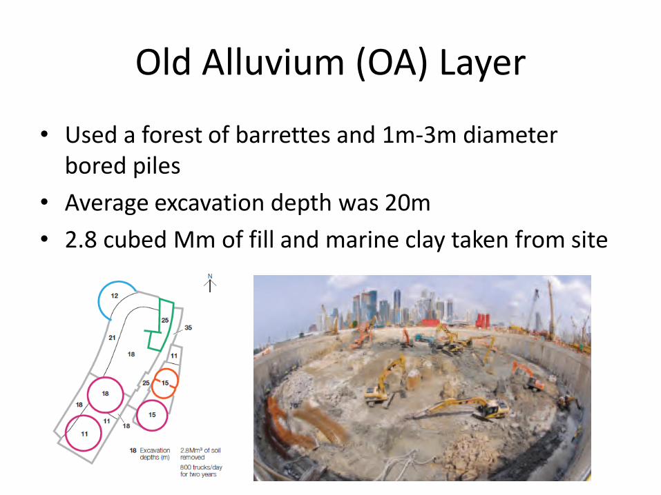
Old Alluvium (OA) Layer
• Used a forest of barrettes and 1m-3m diameter bored piles
• Average excavation depth was 20m
• 2.8 cubed Mm of fill and marine clay taken from site
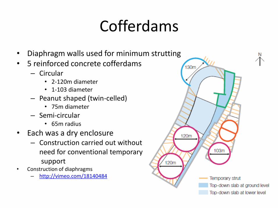
Cofferdams
• Diaphragm walls used for minimum strutting • 5 reinforced concrete cofferdams
– Circular • 2-120m diameter • 1-103 diameter
– Peanut shaped (twin-celled) • 75m diameter
– Semi-circular • 65m radius
• Each was a dry enclosure – Construction carried out without need for conventional temporary support
• Construction of diaphragms – http://vimeo.com/18140484

Plan of retaining walls and foundations for the 3 hotel structures

Jet Grouting
• High-pressure jet of fluid (20-40 MPa) used to break up and loosen the soil in a borehole
• Mixes with a self-hardening grout to form columns, panels and other structures in the ground
• High pressure is used to produce the kinetic energy required
• Waste material (a mix of soil, water and binder) is recovered at the surface then is taken away

DCS Box • Top-down construction
• Minimum temporary props used
• Continuously reinforced diaphragm wall for DCS box • District cooling system
housed in a deep reinforced box
• Shear walls constructed with the box enabled unhindered bulk excavation
• Top-down excavation • Box doubled as a retaining
structure for the deepest excavation in the tunnel where soft marine clay is
• Box has to permanently support the lateral loads from the ground
Shear Wall
Section on plan of adjustable shear pin.
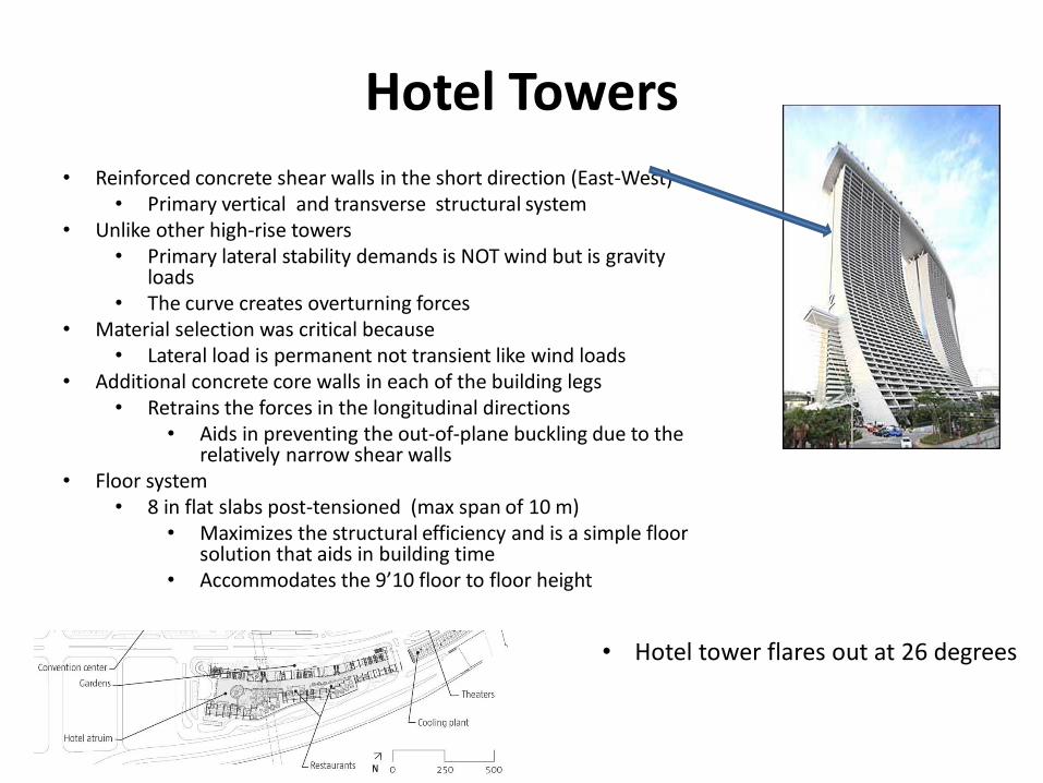
Hotel Towers
• Reinforced concrete shear walls in the short direction (East-West) • Primary vertical and transverse structural system
• Unlike other high-rise towers • Primary lateral stability demands is NOT wind but is gravity
loads • The curve creates overturning forces
• Material selection was critical because • Lateral load is permanent not transient like wind loads
• Additional concrete core walls in each of the building legs • Retrains the forces in the longitudinal directions
• Aids in preventing the out-of-plane buckling due to the relatively narrow shear walls
• Floor system • 8 in flat slabs post-tensioned (max span of 10 m)
• Maximizes the structural efficiency and is a simple floor solution that aids in building time
• Accommodates the 9’10 floor to floor height
• Hotel tower flares out at 26 degrees

Section through top portion
East Elevation
Plan

• Walls and core provide stiffness in short direction
• Cores and sway action between the walls and slabs resist longitudinally
• The ground level
• Base slab of post-tensioned to resist the horizontal thrusts created by the inclined legs
• Level 23 houses the structural steel trusses
• Resists the large shear forces where the two legs meet above the atrium
Hotel Towers
• In the mechanical level
• Is large plate-plate steel elements
• Which are embedded in the concrete walls


• The flare causes the shear walls to flex and drift laterally during construction
• Lots of structural analysis completed to quantify
• Locked-in stresses
• Angular rotation at the top of the tower
• Maximum displacements of elevation in all three axes
• Movement between vertical and inclined walls
• Movement between adjacent bays
• Movement between all three towers
• Self-weight was an issue so it was pre-cambered during construction
• Complication of the material because of
• Creep and shrinkage
• Expected to deform laterally over the next 30 years
• These long-term displacement were accounted for in each aspect of the design
Construction Issues/ Design


• Pre-stressing was introduced into the vertical and inclined shear walls to reduce
• Movements and stresses accumulated during construction
• During construction
• Real time monitor system implemented to compare actual stresses against predicted.
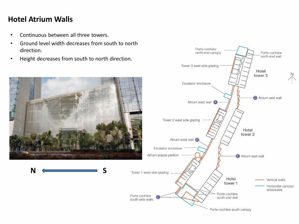
Hotel Atrium Walls
• Continuous between all three towers.
• Ground level width decreases from south to north direction.
• Height decreases from south to north direction.
N S

• Framing consists of steel trusses connected by horizontal transoms. In sync with glass panels.
• Rectangular hollow sections (RHS) are the main structural members.
• Pin connections at base .
• “Temporary” system comprised of steel compression struts and tension cable during construction.
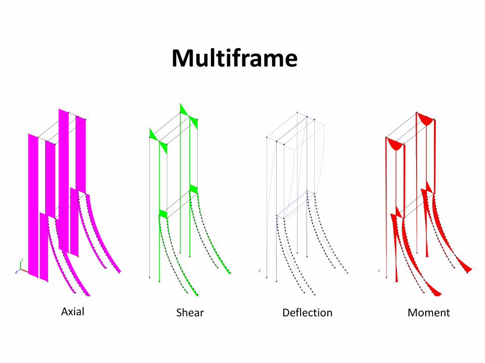
Multiframe
Static Case: Load Case 1 Vy' (kN)
x
y
z
Static Case: Load Case 1 Defl. (in)
x
y
z
Static Case: Load Case 1 Mz' (kip-ft)
x
y
z
Static Case: Load Case 1 Px' (kN)
x
y
z
Axial Shear Deflection Moment
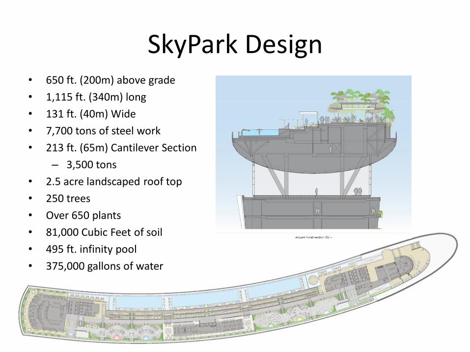
SkyPark Design • 650 ft. (200m) above grade
• 1,115 ft. (340m) long
• 131 ft. (40m) Wide
• 7,700 tons of steel work
• 213 ft. (65m) Cantilever Section
– 3,500 tons
• 2.5 acre landscaped roof top
• 250 trees
• Over 650 plants
• 81,000 Cubic Feet of soil
• 495 ft. infinity pool
• 375,000 gallons of water

Construction Elements
• The cantilever section of the Skypark was built from a system of post-tensioned segmental steel box girders 33 feet deep and 12 feet wide with 1 3/8 inch wide walls and 2 3/8 inch flanges was used.
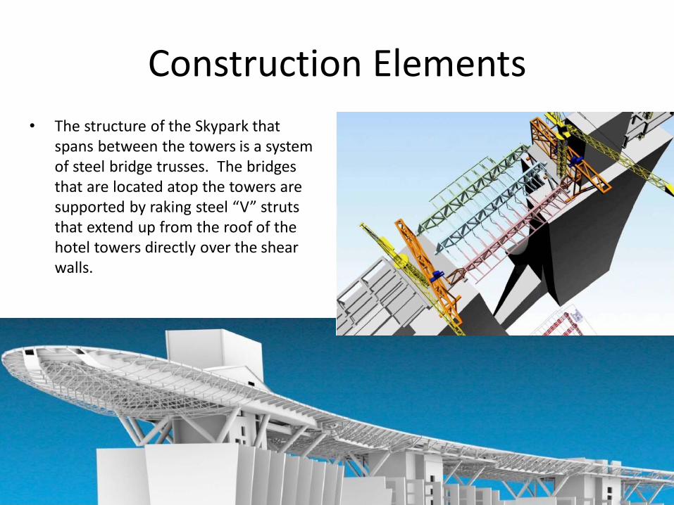
Construction Elements
• The structure of the Skypark that spans between the towers is a system of steel bridge trusses. The bridges that are located atop the towers are supported by raking steel “V” struts that extend up from the roof of the hotel towers directly over the shear walls.

Construction Elements
• Because the towers have dramatically different relative displacements, seismic joints were placed in between each tower to keep pounding from occurring by accommodating the movements due to thermal expansion, creep and shrinkage, and wind lateral movements. http://www.youtube.com/watch?v=FJkYnCh47nA
5T Tuned
Mass
Damper

Dynamic Studies
• Because the towers have dramatically different relative displacements, seismic joints were placed in between each tower to keep pounding from occurring by accommodating the movements due to thermal expansion, creep and shrinkage, and wind lateral movements.

Construction Sequence • 14-main steel segments were prefabricated off site and lifted into place via strand jacks
• This method took cues from bridge building when lifting the segments into place
• Stranding jacking with hydraulic jacks were used to lift the box girders and slide them into place.
• The Cantilever was pre-assembled at grade to assure proper fit and then disassembled and lifted into place and attached to a secondary beam at the top of the hotel tower.
• 7000 tons of steel work was erected in 13 weeks to build the skypark

References
• The Arup Journal
• A496 pdf…Deep Basement & Foundations: Diaphragm Wall, Jet Grouting, Barrette & Bored Piles
• http://www.bachy-soletanche.com/SBF/sitev4_uk.nsf/technique/marina-bay-sands
• SkyPark
– http://newspagedesigner.org/photo/marina-bay-sands-skypark
– http://www.archdaily.com/70186/marina-bay-sands-safdie-architects/skypark-hotel-plan/
– http://www.ctbuh.org/TallBuildings/FeaturedTallBuildings/MarinaBaySands/tabid/1766/language/en-US/Default.aspx
– http://www.scribd.com/doc/40220526/Marina-Bay-Sands-Sky-Park-Cantilever


