IPS-M-IN-120 This Standard is the property of Iranian Ministry of Petroleum. All rights are reserved to the owner. Neither whole nor any part of this document may be disclosed to any third party, reproduced, stored in any retrieval system or transmitted in any form or by any means without the prior written consent of the Iranian Ministry of Petroleum. MATERIAL AND EQUIPMENT STANDARD FOR TEMPERATURE INSTRUMENTS ORIGINAL EDITION MAY 1993 This standard specification is reviewed and updated by the relevant technical committee on Oct. 1997. The approved modifications are included in the present issue of IPS.
Transcript
IPS-M-IN-120
This Standard is the property of Iranian Ministry of Petroleum. All rights are reserved to the owner. Neither whole nor any part of this document may be disclosed to any third party, reproduced, stored in any retrieval system or transmitted in any form or by any means without the prior written consent of the Iranian Ministry of Petroleum.
MATERIAL AND EQUIPMENT STANDARD
FOR
TEMPERATURE INSTRUMENTS
ORIGINAL EDITION
MAY 1993
This standard specification is reviewed and updated by the relevant technical committee on Oct. 1997. The approved modifications are included in the present issue of IPS.
9. TEMPERATURE SWITCHES ....................................................................................................... 21 9.1 Blind-type (Non-Indicating) Temperature Switches .......................................................... 21 9.2 Indicating-type Temperature Switches General: ............................................................... 22
10. MULTIPOINT MICROPROCESSOR-BASED TEMPERATURE RECORDERS........................ 22 11. DOCUMENTATION/LITERATURE............................................................................................. 25 12. INSPECTION AND TEST ........................................................................................................... 26 13. PACKING AND SHIPPING ......................................................................................................... 26 14. GUARANTEE.............................................................................................................................. 26 TABLES : 1 SCALE RANGES FOR LIQUID AND GAS FILLED THERMOMETERS................................... 4 2 SCALE RANGES FOR VAPOR PRESSURE THERMOMETERS............................................. 4 3 APPLICATION DATA FOR FILLED MEASUREMENT SYSTEMS ........................................... 6 4 APPROXIMATE RELATIONSHIP BETWEEN RESISTANCE RATIOAND TEMPERATURE FOR METALLIC SENSING RESISTORS ...................................................... 9 5 THERMOCOUPLE TYPE LETTER DESIGNATIONS.............................................................. 10 6 SYMBOLS FOR TYPES OF THERMOCOUPLE WIRE ........................................................... 10 7 SYMBOLS FOR TYPES OF EXTENSION WIRE..................................................................... 10 8 COLOR CODE-DUPLEX INSULATED THERMOCOUPLE WIRE .......................................... 11 9 COLOR CODE-SINGLE CONDUCTOR INSULATED THERMOCOUPLE EXTENSION WIRE............................................................ 11 10 COLOR CODE-DUPLEX INSULATED THERMOCOUPLE EXTENSION WIRE ................... 11 DRAWINGS: 1 TYPICAL THERMOWELL AND THERMOMETER POCKET (SCREWED) ........................... 27 2 THERMOWELL INSTALLATION (FLANGED) ....................................................................... 30
May 1993
IPS-M-IN-120
2
1. SCOPE
This Standard presents general and minimum requirements for material and equipment of different types of temperature measuring devices, such as: bimetallic & filled-system dial thermometers, thermocouples, RTD elements, thermowells and temperature transmitters. It is intended to be used in oil, gas and petro-chemical industries.
Note:
This standard specification is reviewed and updated by the relevant technical committee on Oct. 1997. The approved modifications by T.C. were sent to IPS users as amendment No. 1 by circular No. 7 on Oct. 1997. These modifications are included in the present issue of IPS.
2. REFERENCES
Throughout this Standard the following dated and undated standards/codes are referred to. These referenced documents shall, to the extent specified herein, form a part of this standard. For dated references, the edition cited applies. The applicability of changes in dated references that occur after the cited date shall be mutually agreed upon by the Company and the Vendor. For undated references, the latest edition of the referenced documents (including any supplements and amendments) applies.
BSI (BRITISH STANDARD INSTITUTION)
BS 1041, Part 3 "IndustrialResistance Thermometry"
BS 1780 "Specification for Bourden Tube Pressure and Vacuum Gages"
BS 1904=IEC 751 "Specification for Industrial Platinum Resistance Thermometers Sensors"
BS 2765 "Specificationfor Dimensions of Temperature Detecting Elements and Corresponding Pockets"
BS 5235 "Specification for Dial-type Expansion Thermometers"
BS 6175 "Temperature Transmitters with Electrical Outputs"
ANSI (AMERICAN NATIONAL STANDARD INSTITUTE)
B 2.1 "Pipe Threads"
ISA (INSTRUMENT SOCIETY OF AMERICA)
MC 96.1 "Temperature Measurement Thermocouples"
RP 12.1 "Electrical Instruments in Hazardous Atmospheres"
ASTM (AMERICAN SOCIETY FOR TESTING AND MATERIALS)
STP 470 B "SpecialTechnical Publication Manual on the use of Thermocouples in Temperature Measurement"
May 1993
IPS-M-IN-120
3
NEC (NATIONAL ELECTRICAL CODE)
Article 500 "Hazardous Classified
Locations"
NEMA (NATIONAL ELECTRICAL MANUFACTURERS ASSOCIATION)
250 "Enclosures for Electrical Equipments (1000 V max.)"
IEC (INTERNATIONALELECTROTECHNICAL COMMISSION)
IEC-79 "Electrical Apparatus for Explosive Atmospheres"
IEC 529 "Classification of Degrees of Protection Provided by Enclosures"
SAMA (SCIENTIFIC APPARATUS MAKERS ASSOCIATION)
PMC 31.1-1980 "Generic Test Methods for the Testing and Evaluation of Process Control Instrumentation"
PMC 33.1-1978 "Electromagnetic Susceptibility of Process Control Instrumentation"
DIN (DEUTSCHES INSTITUTE FUR NORMUNG e.v.)
43760 "Calibration Tables of Resistance Elements for Resistance Thermometers"
IPS (IRANIAN PETROLEUM STANDARD)
IPS-E-GN-100 "Units"
IPS-M-IN-190 "Transmission Systems"
IPS-M-IN-100 "General-Factory Inspection for Instruments and Instruments Systems"
3. UNITS
International System of Units (SI) in accordance with IPS-E-GN-100 shall be used. Except for the temperatures, which shall be in degrees Celsius instead of Kelvin, and for pipes and fittings threads, which shall be in inches of NPT.
4. DIAL-TYPE THERMOMETERS
4.1 Filled-system Thermometers
4.1.1 Dimensions
- Detecting Elements:
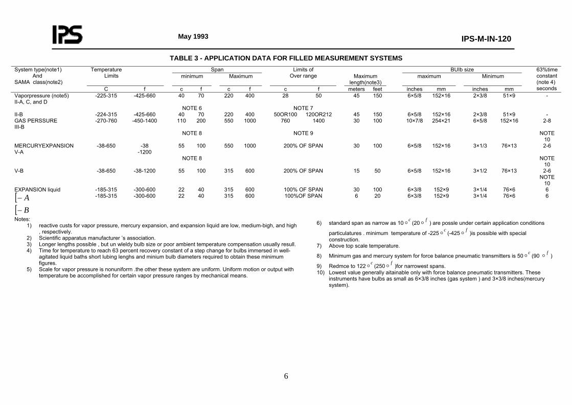
The dimensions and related tolerances of the detecting element or bulb size shall be as specified in Table 3.
- Insertion Length:
May 1993
IPS-M-IN-120
4
Refer to attached drawings DWG No. 1 and DWG No. 2.
- Capillary Tubing:
The length of the capillary tube shall be normally 5 meters, unless otherwise specified in related data sheets.
- The overall outside diameter of the tubing connecting the detecting element to the gage shall be not less than 2.5 mm, whether it is a thick-walled capillary or a sheathed fine capillary.
- Dial Size:
The nominal diameter of dial shall be normally 150 mm, unless otherwise specified in related data sheets.
4.1.2 Gage mounting
Normally shall be surface type, unless otherwise specified in related data sheets.
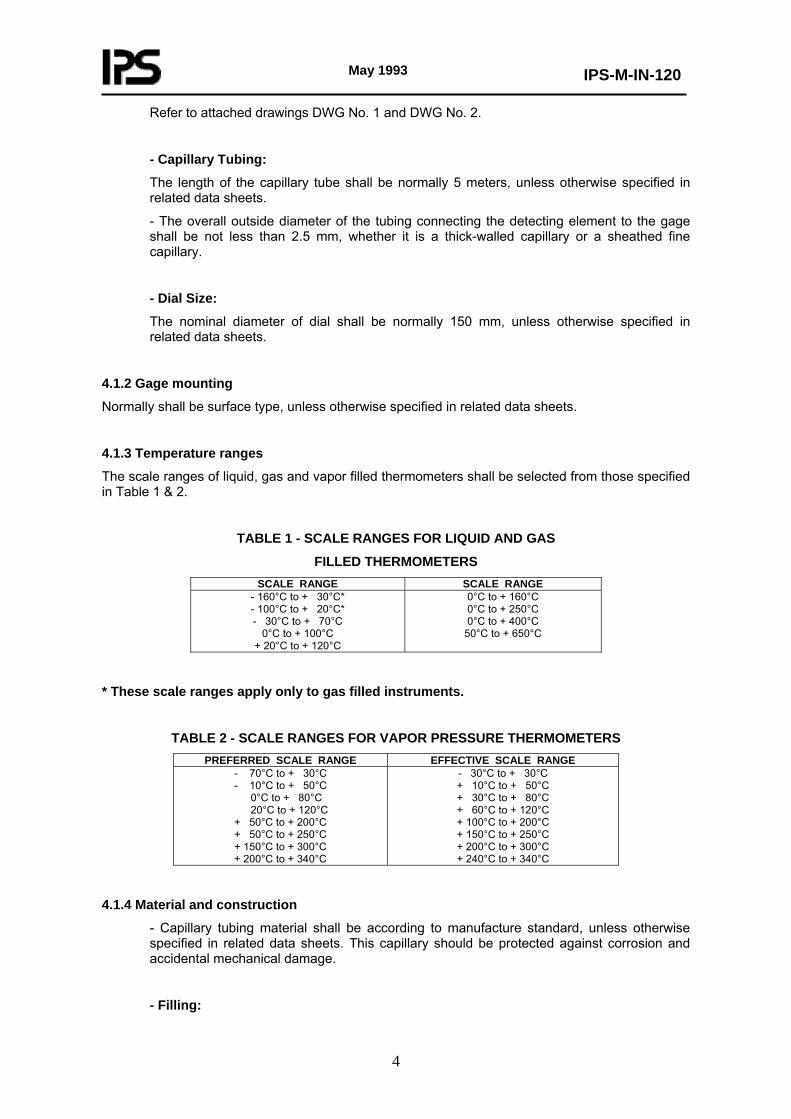
4.1.3 Temperature ranges
The scale ranges of liquid, gas and vapor filled thermometers shall be selected from those specified in Table 1 & 2.
TABLE 1 - SCALE RANGES FOR LIQUID AND GAS
FILLED THERMOMETERS SCALE RANGE SCALE RANGE
- 160°C to + 30°C* - 100°C to + 20°C* - 30°C to + 70°C
0°C to + 100°C + 20°C to + 120°C
0°C to + 160°C 0°C to + 250°C 0°C to + 400°C
50°C to + 650°C
* These scale ranges apply only to gas filled instruments.
TABLE 2 - SCALE RANGES FOR VAPOR PRESSURE THERMOMETERS PREFERRED SCALE RANGE EFFECTIVE SCALE RANGE
- 70°C to + 30°C - 10°C to + 50°C 0°C to + 80°C
20°C to + 120°C + 50°C to + 200°C + 50°C to + 250°C + 150°C to + 300°C + 200°C to + 340°C
- 30°C to + 30°C + 10°C to + 50°C + 30°C to + 80°C + 60°C to + 120°C + 100°C to + 200°C + 150°C to + 250°C + 200°C to + 300°C + 240°C to + 340°C
4.1.4 Material and construction
- Capillary tubing material shall be according to manufacture standard, unless otherwise specified in related data sheets. This capillary should be protected against corrosion and accidental mechanical damage.
- Filling:
May 1993
IPS-M-IN-120
5
Shall be selected according the required range, as specified in Table 3, unless otherwise specified in related data sheets.
- Detecting Element:
Manufacturer standard shall be accepted after agreement of the user.
- Dial:
Shall be of a suitable metal as specified in BS 5235, which specifies normally aluminum.
- Pointer:
Shall be of suitable metal, as specified in BS 5235.
- Case:
Shall be manufactured from material which gives adequate protection against environmental conditions including shocks which are likely to be encountered during transport, storage, installation, normal operation and maintenance, which is normally die-cast aluminium.
- Window:
Shall be of sheet glass having a uniform thickness of not less than 3 mm and shall be free from defects.
- Protection Against Weather and Atmospheric Conditions:
Gages for indoor use shall be designed and constructed so as to be proof against ingress of dust and mist spray, according to IP 65 of IEC-529.
Gages for outdoor use shall have adequate protection against atmospheric conditions which are likely to be encountered during normal operation.
Notes: 1) reactive custs for vapor pressure, mercury expansion, and expansion liquid are low, medium-bigh, and high
, respectively. 2) Scientific apparatus manufacturer ’s association. 3) Longer lengths possible , but un wleldy bulb size or poor ambient temperature compensation usually resull. 4) Time for temperature to reach 63 percent recovery constant of a step change for bulbs immersed in well-
agitated liquid baths short lubing lenghs and minium bulb diameters required to obtain these minimum figures.
5) Scale for vapor pressure is nonuniforrn .the other these system are uniform. Uniform motion or output with temperature be accomplished for certain vapor pressure ranges by mechanical means.
6) standard span as narrow as 10 (20 ) are possle under certain application conditions
particulatures . minimum temperature of -225c
(-425f
)is possible with special construction.
co foo o
7) Above top scale temperature.
8) Minimum gas and mercury system for force balance pneumatic transmitters is 50 (90 ) c f
co fo9) Redmce to 122 (250 )for narrowest spans. o o10) Lowest value generally aitainable only with force balance pneumatic transmitters. These
instruments have bulbs as small as 6×3/8 inches (gas system ) and 3×3/8 inches(mercury system).
TABLE 3 - APPLICATION DATA FOR FILLED MEASUREMENT SYSTEMS
May 1993
IPS-M-IN-120
7
4.1.5 Performance
- Errors, shall not exceed ±1.0% of the difference between the maximum and minimum values of the effective scale range for liquid or gas, and ±1.5% for vapor filled thermometers.
- The error per °C change in the ambient temperature surrounding the gage and capillary tube shall not exceed ±0.03% of the difference between the maximum and minimum values of the effective scale range for liquid or gas, and ±0.05% for vapor filled thermometers.
4.2 Bimetallic Thermometers
- General:
This type of thermometers shall be either rigid stem vertical type or universal angle, for local application, with external adjustment for re-calibration.
- Dial Size:
Normally is 150 mm, nominal diameter, unless otherwise is specified in related data sheets.
- Dial Material:
Aluminium, unless otherwise specified in data sheet.
- Dial Color:
Black figures on white dial.
- Pointer:
Black pointer.
- Scale Range:
As specified in related data sheets.
- Element:
Bi-metal multiple helix.
- Stem:
6 mm ( ¼ in.) diameter, 316 s.st., unless otherwise specified in data sheets.
- Connection:
(½ in.) NPT, fixed or adjustable compression gland 316 s.st., bottom connection, unless otherwise specified in related data sheets.
- Insertion Length:
100 mm (4 in.) minimally excluding threads, unless otherwise specified in related data sheets. See also the attached drawings, DWG No. 1 and DWG No. 2.
May 1993
IPS-M-IN-120
8
- Thermowell:
316 s.st., separable well, from solid bar stock, screwed (1 in.) NPT external thread, and (½ in.) NPT internal thread. Rating 100 barg, unless otherwise specified in related data sheets.
- Case:
st.st., Die-cast aluminium, or as specified in data sheets fume and weather proof, to BS 1780.
- Bezel Ring:
Screwed die-cast aluminium alloy.
- Window:
Heavy plate glasses, breakage resistance, shatter proof.
- Mounting:
Direct mounting, locally.
- Accuracy:
Better than ± 1% of full span.
5. RESISTANCE-TYPE DETECTORS (RTD)
- Two types of wire shall generally be used in resistance elements, nickel for ranges up to 315°C, and platinum for ranges up to 800°C, a third type copper, shall be used in large motor windings up to 150°C.
- Resistance elements shall conform to:
BS 1041-Part 3 Industrial Resistance Thermometry
BS 1904=IEC 751 Specification for Industrial Platinum Resistance Thermometers Sensors
BS 2765 Specification for Dimensions of Temperature Detecting Elements and Corresponding Pockets.
DIN 43760 Calibration Tables of Resistance Elements for Resistance Thermometers
- Terminal block enclosure should have sufficient environmental protection not less than IP 65 and should be suitable for wire sizes up to 2.5 mm2.
- Sufficient space at the terminal box should be provided to accommodate the maximum 4-terminating wires.
- Conduit connection size shall be M20 ×1.5.
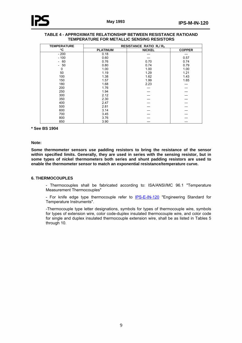
- Temperature-resistance relations shall be as mentioned in Table 4
May 1993
IPS-M-IN-120
9
TABLE 4 - APPROXIMATE RELATIONSHIP BETWEEN RESISTANCE RATIOAND TEMPERATURE FOR METALLIC SENSING RESISTORS
RESISTANCE RATIO Rt / R0TEMPERATURE °C PLATINUM NICKEL COPPER
Some thermometer sensors use padding resistors to bring the resistance of the sensor within specified limits. Generally, they are used in series with the sensing resistor, but in some types of nickel thermometers both series and shunt padding resistors are used to enable the thermometer sensor to match an exponential resistance/temperature curve.
6. THERMOCOUPLES
- Thermocouples shall be fabricated according to: ISA/ANSI/MC 96.1 "Temperature Measurement Thermocouples"
- For knife edge type thermocouple refer to IPS-E-IN-120 "Engineering Standard for Temperature Instruments".
-Thermocouple type letter designations, symbols for types of thermocouple wire, symbols for types of extension wire, color code-duplex insulated thermocouple wire, and color code for single and duplex insulated thermocouple extension wire, shall be as listed in Tables 5 through 10.
May 1993
IPS-M-IN-120
10
TABLE 5 - THERMOCOUPLE TYPE LETTER DESIGNATIONS TYPE NOMINAL
TEMPERATURE RANGE MATERIAL IDENTIFICATION
(POSITIVE MATERIAL IN CAPS)
B
E J
K
R
S
T
0 to 1820°C
- 270 to 1000°C
- 210 to 760°C
- 270 to 1372°C
- 50 to 1768°C
- 50 to 1768°C
- 270 to 400°C
PLATINUM-30 PERCENT RHODIUM VERSUSPLATINUM-6 PERCENT RHODIUM NICKEL-10 PERCENT CHROMIUM VERSUS COPPER-NICKEL IRON VERSUS COPPER-NICKEL NICKEL-10 PERCENT CHROMIUM VERSUS NICKEL-5PERCENT (ALUMINUM, SILICON) PLATINUM-13 PERCENT RHODIUM VERSUS PLATINUM PLATINUM-10 PERCENT RHODIUM VERSUS PLATINUM OPPER VERSUS COPPER-NICKEL
TABLE 6 - SYMBOLS FOR TYPES OF THERMOCOUPLE WIRE THERMOELEMENTS
TYPE POSITIVE NEGATIVE B E J K R S T
BP EP JP KP RP SP TP
BN EN JN KN RN SN TN
TABLE 7 - SYMBOLS FOR TYPES OF EXTENSION WIRE TYPE COMBINATION POSITIVE NEGATIVE EXTENSION WIREELEMENTS***
* Both type R or S Thermocouples use the same SX compensating extension wire.
** Special compensating extension wires are not required for reference junction temperatures up to 100°C.
Generally copper conductors are used. However, proprietary alloys may be obtained for use at higher reference junction temperatures.
*** These thermocouple materials are defined by their EMF characteristics. Alloy compositions may vary from lot to lot.
May 1993
IPS-M-IN-120
11
TABLE 8 - COLOR CODE-DUPLEX INSULATED THERMOCOUPLE WIRE THERMOCOUPLE COLOR OF INSULATION
TYPE POSITIVE NEGATIVE OVERALL* POSITIVE* NEGATIVE E J K T
EP JP KP TP
EN JN KN TN
BROWN BROWN BROWN BROWN
PURPLE WHITE
YELLOW BLUE
RED RED RED RED
* A tracer color of the positive wire code color may be used in the overall braid.
TABLE 9 - COLOR CODE-SINGLE CONDUCTOR INSULATED THERMOCOUPLE
EXTENSION WIRE EXTENSION WIRE TYPE COLOR OF INSULATION
TYPE POSITIVE NEGATIVE POSITIVE Negative B
E J
K
R or S
T
BPX
EPX
JPX
KPX
SPX
TPX
BNX
ENX
JNX
KNX
SNX
TNX
GRAY
PURPLE
WHITE
YELLOW
BLACK
BLUE
RED-GRAT TRACE
RED-PURPLE TRACE
RED-WHITE TRACE
RED-YELLOW TRACE
RED-BLACK TRACE
RED-BLUE TRACE
* The color identified as a trace may be applied as a tracer, braid, or by any other readily identifiable means.
Note of caution:
In the procurement of random lengths of single conductor insulated extension wire, it must be recognized that such wire is ommercially combined in matching pairs to conform to established temperature-EMF curves. Therefore, it is imperative hat all single conductor insulated extension wire be procured in pairs, at the same time, and from the same source.
TABLE 10 - COLOR CODE-DUPLEX INSULATED THERMOCOUPLE EXTENSION WIRE EXTENSION WIRE TYPE COLOR OF INSULATION
TYPE POSITIVE NEGATIVE POSITIVE Negative B
E J
K
R or S
T
BPX
EPX
JPX
KPX
SPX
TPX
BNX
ENX
JNX
KNX
SNX
TNX
GRAY
PURPLE
WHITE
YELLOW
BLACK
BLUE
RED-GRAT TRACE
RED-PURPLE TRACE
RED-WHITE TRACE
RED-YELLOW TRACE
RED-BLACK TRACE
RED-BLUE TRACE
* A tracer having the color corresponding to the positive wire code color may be used on the negative wire color code.
- Wire sizes for non-sheathed thermocouples, shall be normally as follows:
For J,K and E-type: 8.4 mm2 (8 AWG), 2 mm2 (14 AWG), 0.5 mm2 (20 AWG), 0.204 mm2 (24 AWG), and .080 mm2 (28 AWG).
For T-type: 2 mm2 (14 AWG), 0.5 mm2 (20 AWG), 0.204 mm2 (24 AWG), and 0.080 (28 AWG).
May 1993
IPS-M-IN-120
12
For R,S and B-type: 0.204 mm2 (24 AWG) only.
- For extension wires the sizes shall be:
2 mm2 (14 AWG), 1.3 mm2 (16 AWG), and 0.5 mm2 (20 AWG), either singly or inpairs. 1.3 mm2 (16 AWG) is most commonly used, 0.5 mm2 (20 AWG) and smaller may be used when bundled and reinforced to provide trength for pulling.
These sizes apply to all types of extension wires.
- For more details on extension wires connection and cabling refer to: IPS-M-IN-190 "Transmission Systems".
Note:
Wire sizes which are nominally equivalent to "AWG" in European standards shall be accepted also.
7. THERMOWELLS
- Normally thermowells shall be 316 stainless steel, unless otherwise indicated in related data sheets.
- Thermowells shall be fabricated from solid bar stock, the bore shall be concentric to 10% of wall thickness.
- The well shall be polish finished below mounting threads or flange to 0.25 microns.
- The external thread of screwed-type thermowells shall be 1in. NPT, and the internal thread shall be ½ in. NPT.
- For more details refer to attached drawings No. 1 and 2.
- For additional informations reference to be made to BS 2765 "Specification for Dimensions of Temperature
Detecting Elements and Corresponding Pockets", latest edition.
8. TEMPERATURE TRANSMITTERS
8.1 Electro-pneumatic Transmitters
General:
This type of transmitters, shall be non-indicating (blind), transmitters of continuous balance type, which converts the hermocouple, resistance element, or any other mv source signal into (0.2-1 barg) pneumatic signal, with the following eatures:
- Actuation:
When thermocouple input is specified, potentiometric type instrument with amplifier and automatic cold junction ompensation shall be provided.
- Thermocouple Type:
Normally shall be J or K-type.
May 1993
IPS-M-IN-120
13
- Accuracy:
Shall be ± 1% of full range, or better.
- Range:
Shall be as specified in related data sheets.
- Power Supply:
24 V d.c. preferable, 115 V, 50 Hz, with suitable voltage stabilizer, constant voltage supply unit is acceptable.
- Balance Speed:
Maximum full scale travel in 12 seconds @ 50 Hz.
- Air Supply:
1.4 barg.
- Output Signal:
0.2-1 barg.
- Case and Cover:
Heavy gage sheet steel.
- Dimensions:
Manufacturer standard.
- Connection:
¼ in. ANSI B2.1 NPT, at back of case for air supply, air output and air purging.
Plugged conduit entry, holes on back or top of case.
- Mounting:
Rack mounting, or pipe mounting with bracket U-bolt, for 50 mm (2 in.) stand pipe.
- Burn out Feature:
Thermocouple burn out feature up scale or down scale drive, with last measurement hold, if specified.
- Name Plate:
Same as 8.4.2.
May 1993
IPS-M-IN-120
14
8.2 Fi led System-pneumatic Transmitters
Gene al:
These transmitters shall be either, non-indicating (blind), or indicating-type, of motion balance type, which converts the emperature signal into pneumatic (0.2-1bar g) signal, with the following features:
- Element:
Shall be either gas filled, or liquid and mercury filled. Gas filled thermal system class IIIA.
Liquid expansion thermal system class IA.
- Accuracy:
Shall be 0.5% of span or better.
- Range:
As specified in related data sheets.
- Air Supply:
1.4 barg.
- Output Signal:
(0.2-1) barg.
- Case and Cover:
Heavy cast aluminium.
- Connection:
Screwed, ¼ in. ANSI B2.1 NPTF.
- Mounting:
Pipe mounting with bracket U-bolt for 50 mm (2 in.) stand pipe.
- Compensation:
Fully compensated.
- Capillary Tubing:
Tubing shall be according to manufacturer standard, with 304 s.st flexible armour.
- Tubing Length:
Shall be normally 5 meters, or as specified in related data sheets.
May 1993
IPS-M-IN-120
15
- Element Material:
Bulb, jam nut and bushing in 316 s.st.
- Bulb Rating:
Standard adjustable union teflon packing, suitable for 69 barg at 205°C.
- Bulb Diameter:
10 Mm (3/8 in.), O.D unless otherwise specified in related data sheets.
- Bulb Union Connection:
Bushing ½ in. ANSI B2.1 NPT, external thread.
- Over Range Protection:
Up to 100% of span.
- Thermometer Pocket:
316 s.st. or higher grade alloy as specified in data sheets, separable from solid bar stock. See also the attached drawings, No. 1 and DWG No. 2.
- Thermowell Connection:
1 in. ANSI B2.1 NPT MALE external thread, ½ in. ANSI B2.1 NPT FEMALE internal thread.
- Insertion Length:
Refer to drawings No. 1 and 2 attached herewith.
- Case and Door:
Normally shall be fiber glass, reinforced gray polyester moulding case. Hinged door in fiber glass reinforced henylene oxide, with blue polyurethane finish.
Enclosure classification shall be NEMA 3, weather-proof or equivalent, such as IP 54 to IEC-529.
Normally shall be eccentric scale, effective length is 150 mm, with white dial, blacked marking and fluorescent
red pointer.
- Element Capillary Entry:
Slotted hole for tubing in bottom of case.
May 1993
IPS-M-IN-120
16
- Ambient Temperature Limits:
From -29°C to +82°C.
- Ambient Temperature Effect:
Shall be less than 1% of 55°C change.
- Name Plate:
Same as 8.4.2.
8.3 Electronic Transmitters
General:
These type of transmitters shall be either indicating or blind-type, accept millivolt input from a standard thermocouples, or ohmage resistant from a resistance element and provide 1-5 V, or 4-20 mA output signal, via 2-wire system, with the following general features:
- Mounting:
Panel (rear)/wall (surface) mounting, or stand pipe mounting with 50 mm (2 in.) universal bracket.
- Input:
Millivolt input from thermocouple, or RTD (pt 100).
- Output:
1-5 V, or 4-20 mA into min. 250 ohm, with 130 nA current offset, manufacturer standard to be followed.
- Span:
2-100 mv. (Continuously adjustable).
- Zero Suppression:
±50 mv. (Continuously adjustable).
- Input Impedance:
100 k ohm/mv.
- Thermocouple Type:
Normally shall be either J or K type, unless otherwise specified in related data sheets, with automatic cold junction compensation.
May 1993
IPS-M-IN-120
17
- Range:
Continuous operation up to 1200°C max.
- Electrical Power Supply:
Preferably 24 V, d.c. ±0.5 into max. 600 Ω
- Electrical Classification:
Normally shall be intrinsic safety and certified by acceptable association, such as BASEEFA.
Enclosure classification shall be weather proof according to IP 65 of IEC-529.
- Electrical Protection:
Instrument to be individually fused.
- Input Circuit Protection:
Output shall be drived up scale, or down scale if input opens or breaks.
- Ambient Temperature Limits:
From -30°C to 85°C.
- Ambient Temperature Effect:
Less than ±0.2% of span per 10°C.
- Housing:
Die-cast aluminum with baked vinyl finish.
- Window:
Shatter proof (for indicating type transmitters).
- Dial:
Sector scale effective length 65 mm (2 ½ in.), black markings on white background (for indicating type transmitters).
These transmitters are microprocessor-based type, and compatible with a variety of temperature sensors, including 2, 3, and 4-wire RTDs, thermocouples and other resistance and millivolt inputs.
The sensor type is software selectable from the hand-held terminal (HHT). It provides either 4-20 mA standard signal, and/or digital signal.
8.4.1 Functional specifications
- Isolation:
The input is galvanically isolated from the output and ground.
- Inputs:
RTD (PT 100), or type J or K thermocouple, as specified in related data sheets.
- Outputs:
Two-wire 4-20 mA, linear with temperature or linear with input, or digital output signal superimposed on 4-20 mA signal.
- Power Supply:
Preferably 24 V, d.c., ±0.5 V into max. 600 Ω.
- Reverse Polarity Protection:
Shall be provided.
- Local Limitations:
Minimum load shall be 250, Ω manufacturer’s standard to be followed.
- Indication:
Signal indicator shall be provided, with accuracy better than ±2%.
May 1993
IPS-M-IN-120
19
- Hazardous Location (Electrical Classification):
Normally shall be intrinsic safety, and certified by acceptable associations, such as: BASEEFA unless otherwise specified.
- Temperature Limits:
i) Ambient: -40° to +75°C.
ii) Storage: -50° to +120°C.
- Loss Of Input/Failure Alarm:
If self-diagnostics detect a sensor burn out or gross transmitter failure, the analogue signal shall be driven either below 4 mA or above 20 mA to alert the user (high or low alarm signal shall be user-selectable by internal jumper).
- Humidity Limits:
0-100%, and shall meet the requirements of SAMA 31.1 section 5.2.
- Turn-On Time:
Performance within specifications less than 5.0 seconds after power is applied to transmitter.
- Update Time:
0.5 seconds, approx.
8.4.2 Physical specification
- Electrical Connection:
M20 ×1.5.
- Materials of Construction:
i) Electronic housing: Low-copper aluminium, NEMA 4X, or IEC-code IP 65.
ii) Paint: Epoxy-polyester.
iii) Cover o-rings: Buna-N.
- Mounting:
Normally shall be direct mounting or shall be with brackets for 2-inch stand pipe mounting, as specified in related data sheets.
- Name Plate:
Stainless steel data plate fastened to electronics housing with stainless steel screws. Includes the following information:
a) instrument tag No;
May 1993
IPS-M-IN-120
20
b) manufacturer’s serial No., model No;
c) temperature range;
d) max. working temperature;
e) electrical, pneumatic power supply (if applicable);
f) over range protection temperature.
8.4.3 Performance specifications
- Accuracy:
Better than ±0.1% of calibrated span for analogue signal, ±0.07% of calibrated span for digital signal.
- Stability:
±0.1% of reading or 0.1°C whichever is greater, for six months.
- Repeatability:
Better than 0.05% of calibrated span.
- Ambient Temperature Effect:
Shall be better than 0.2% of span.
- Power Supply Effect:
Less than ±0.005% of span per volt.
- Vibration Effect:
The total effect (maximum effect at any point in calibrated range) is 0.1% of reference span for acceleration up to 30 m/s2, and meets SAMA PMC 31.1.
- Relative Humidity Effect:
Negligible between 0 and 100% RH.
- RFI Effect:
To be tested per SAMA PMC 33.1 from 20 to 1000 MHz, cables in conduit: class 3 ABC: ±0.1% span at 30 v/m, cables unshielded: class 2 ABC: ±1% span at 10 v/m.
- Calibration Facility:
Built-in calibration jack, if specified.
May 1993
IPS-M-IN-120
21
9. TEMPERATURE SWITCHES 9.1 Blind-type (Non-Indicating) Temperature Switches General: Temperature switches are devices, which provides an electrical contact (potential free), to be used for different purposes, such as trip order, or alarm signal...etc. These switches normally are non-indicating (blind-type) or indicating-type.
- Element: Bimetallic or filled-type, normally liquid filled. - Mounting: Direct mounting, unless otherwise specified in related data sheets. - Range: As specified in related data sheets. - Insertion Length: Normally is 150 mm, unless otherwise specified in related data sheets. See also the attached drawings, No. 1 and 2. - Thermowell: Normally thermowell is required, material shall be 316 s.st., or higher grade alloy as specified in data sheet, drilled from solid bar stock, screwed 1 in. NPT (external), and ½ in. NPT (internal), minimum rating shall be 100 barg. See also the attached drawings, 1 and 2. - Capillary (for filled-type): Manufacturer standard capillary tube with at least 304 s.st. armour, its length shall be normally 5 meters, unless otherwise specified in related data sheets. - Housing and cover: Shall be die-cast aluminium. - Electrical Classification: Normally shall be intrinsic safety and certified by acceptable association, such as BASEEFA, unless otherwise specified. - Switch, Electrical Requirement: Switches shall be normally SPDT-type, 110 a.c., 10 Amp, or 30/125 V d.c. 5/0.5 Amp, hermetically-sealed, mercury or snap-action, Ag-Ni 80/20% contacts (preferably). - Set Point Shift Due To Ambient Temperature Changes: Shall be less than 0.1% of full scale. - Dead Band: Shall be less than 1% of span.
May 1993
IPS-M-IN-120
22
- Bulb Diameter: 10 mm, unless otherwise specified in related data sheets. - Bulb Connection: Shall be ½ in. NPT M. - Name Plate: See 8.4.2.
9.2 Indicating-type Temperature Switches General: This type of temperature switches, shall be normally local mounted, dial-type, and either bimetallic or filled-system, with potential free contacts.
- All features which apply to dial-type temperature indicators are also applicable here. - Electrical Classification: Normally shall be intrinsic safety and certified by acceptable association, such as BASEEFA, unless otherwise specified. - Wiring: Normally junction box shall be at right side of the switch.
Material: Black PA6-nylon, or equivalent. Weather Protection: IP65, unless otherwise specified in related data sheets. Ambient Temperature: From -40°C to 80°C. Insulation Resistance: 500 V d.c., 100 M between measuring and ground terminals. Dielectric Strength: 500 V a.c. for 1 min. between I/P and O/P terminals. Entry: M20 ´1.5, bottom entry cable gland with retainer clamp. 4-wire + earth terminals. Terminal Size: 2.5 mm2 to accept stranded wire.
- Name Plate: Same as 8.4.2.
10. MULTIPOINT MICROPROCESSOR-BASED TEMPERATURE RECORDERS 10.1 Performance Specifications
- Measuring Accuracy: ±0.1% of measured range, ±1 digit.
- Measuring and Recording Points: Either 15 or 30 points, or as specified. - Input Signals: Thermocouples, RTD, d.c. voltages, and d.c. current. - Operating Conditions
Ambient Temperature: 0 to 40°C. Relative Humidity: 20 to 80%. Supply Voltage and Frequency: 120 V a.c.,50 Hz, or 240 V a.c., 50 Hz, with switch selection. Allowable voltage fluctuation is ±10% of rated value.
- Battery Backup: If power is interrupted, lithium battery backup preserves settings in memory. - Range Setting: Input type and range are set by operator (key input). - Scale Setting: Minimum and maximum values, and units of measurement, are set by operator (key input). - Allowable Signal Source Resistance: To be specified by the manufacturer. - Recording Type: Dot type print, six ribbon colors, analog recording in six colors, digital recording in block, unless otherwise specified. - Chart Speed: 25 mm/h, if not specified, freely set from 1 to 999 mm/h. - Recording Speed: 30 points/5 seconds, if not specified. - Chart Description: Strip chart type with an overall width of 318 mm (12.5 in.) and a total length of 20 m. The
May 1993
IPS-M-IN-120
24
effective (usable) recording width for an analog record is 250 mm equally graduated into 100 divisions. For digital recording, the effecting recording width is 21 mm-left, and 18 mm-right.
Note: Another chart dimensions are accepted after agreement of the user.
- Data Recording Analog Trend Recording
Digital Recording: Prints channel number and data at a constant time, or at a designated time. Data Print: Analog record is momentarily stopped and printed on request.
- Alarm Recording: Analog recording is performed when an alarm is triggered, and the time and relay number are printed in the right margin of the chart. - Message Recording: The time (hour and minute) and message are printed on request. - Time Line Recording: Automatic time recording (every 30 minutes) with a red line at both ends of the chart. Unless otherwise specified. - Time Printing: The time (hour and minute) are printed in the left margin of the chart every hour. - Real Scale Printing: The minimum and maximum scale values are printed on the left and right side of the chart, respectively, every hour. - Unit Printing: Units are recorded on the right side of the chart at fixed intervals. - Data Indicator: Fluorescent display, 16 characters, 9 mm character height, 5 × 7 dots (width × height).
Note: Another character dimensions are also accepted, after agreement of the user.
- Display Item
For Measurement Input: Channel Number, actual scale value, units, and chart speed. For Clock Display: Month, day, hour, minute and chart speed.
May 1993
IPS-M-IN-120
25
- Alarm System: Individual setting and common output by high/low limit. - Insulation Resistance 500 V d.c. > 20 M Ω between measuring and ground terminals. 1000V d.c. > 20 M Ω between power and ground terminals, and between power and measuring terminals. - Dielectric Strength: 1500 V a.c. for one minute between measuring and ground terminals, between power and ground terminals, and between power and measuring terminals.
10.3 Physical Specifications
- Enclosure: Normally is steel with grey finish. - Front Panel: Normally is die cast aluminium with black finish. - Mounting: Normally is flush to panel. - Electrical Connections: All input signals, power, earth (ground), and alarm connections are located on the rear panel. Terminations are made with screw terminals. Also on the rear panel are the power switch, fuse, voltage selection witch, and communications interface connection.
11. DOCUMENTATION/LITERATURE 11.1 At Quotation Stage Suppliers are to provide the following in the numbers requested at the time of quotation:
a) comprehensive descriptive literature; b) list of recommended commissioning spares with prices; c) details of any special tools required with prices.
11.2 At Ordering Stage Suppliers are to provide the following in quantities and at times as detailed on the order:
a) list of recommended spares for two years continuous operation; b) illustrated comprehensive spare parts manual with part numbers suitable for warehouse stocking; c) illustrated installation and operating instructions; d) maintenance manuals.
Note: The above shall include identification of all proprietary items. All drawings and literature shall be in English language and show all dimensions, capacities, etc., in metric units. The order number must be prominently shown on all documents.
May 1993
IPS-M-IN-120
26
Drawings are to be properly protected and packed and negatives must be dispatched in a strong cardboard cylinder. Drawings must be rolled not folded. 12. INSPECTION AND TEST
- Inspection by appointed representative will consist of but not necessarily be confined to: 12.1 Visual and Dimensional Checks 12.2 Hydraulic and Functional Test Where Applicable
- Certified test reports shall be provided for each instrument. - The user reserves the right to reject individual instrument for bad workmanship or defects. - Detailed inspection requirements are specified in IPS-M-IN-100, factory inspection for instruments and instruments systems.
13. PACKING AND SHIPPING Equipment must be carefully protected and packed to provide adequate protection during transit to destination and shall be in accordance with any special provision contained in the specification or order. Special attention must be given to protection against corrosion during transit. All bright and machined parts must be painted with a rust preventative. Ancillary items forming an integral part of the equipment should be packed preferably in a separate container if the equipment is normally cased or crated. Alternatively the ancillary items should be fixed securely to the equipment and adequate precaution taken to ensure that the items do not come loose in transit or be otherwise damaged. Instruments having delicate movements and assembled into panels for inspection and test must be replaced in makers special shock absorbing packages for transit, all connections being marked for remounting in IRAN. Such instruments to be packed in same case as associated panel, but protected by a bulkhead or equivalent packing arrangement. 14. GUARANTEE Vendor shall guarantee the following when the instrument is operated in accordance with the written operating instructions. 14.1 Designed performance and quality under conditions per specification. 14.2 Instrument is free from fault in design, workmanship and material to fulfill satisfactorily the operating conditions specified. 14.3 Spare parts guarantee for minimum 10 years and performance guarantee for one year after installation or 18 months after shipment whichever is closer.
THERMOWELLS
May 1993
IPS-M-IN-120
27
* All dimensions are in millimeters.
TYPICAL DRAWING 1
TYPICAL THERMOWELL AND THERMOMETER POCKET (SCREWED)
May 1993
IPS-M-IN-120
28
Notes:
1) The details shown of the hexagon and plug are typical only. Manufacturers standards may also be considered.
2) The well, plug, chain and rings shall be stainless steel type AISI-316.
3) The well shall be fabricated from solid bar stock, the bore shall be concentric to 10% of wall thickness.
4) The well shall be polished below mounting threads to 0.25 microns surface finish.
5) The well shall have an (ANSI B2.1 one inch taper pipe thread) modified to have at least twelve effective threads, two of which are below a standard ring gage.
This provides two additional full threads at each end beyond a standard pipe thread engagement.
6) The well shall withstand an internal hydrostatic test pressure of (140 bar).
7) The maximum cold working pressure is (70 barg).
8) On an insulated line, the thermowell shall be insulated up to the bottom of the hexagon head. "T" dimension shall include a 50 mm lagging extension.
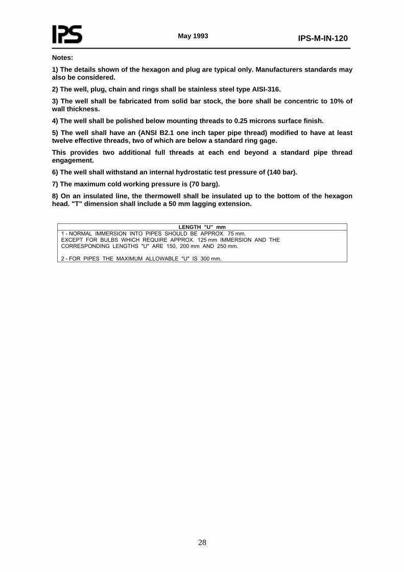
LENGTH "U" mm
1 - NORMAL IMMERSION INTO PIPES SHOULD BE APPROX. 75 mm. EXCEPT FOR BULBS WHICH REQUIRE APPROX. 125 mm IMMERSION AND THE CORRESPONDING LENGTHS "U" ARE 150, 200 mm AND 250 mm. 2 - FOR PIPES THE MAXIMUM ALLOWABLE "U" IS 300 mm.
May 1993
IPS-M-IN-120
29
* For vessels, blind flange size shall be 50 mm (2 inches) and Length "U" may be larger than listed.
1 - NORMAL IMMERSION INTO PIPES SHOULD BE APPROX. 75 mm. EXCEPT FOR BULBS WHICH REQUIRE APPROX. 125 mm IMMERSION AND THE CORRESPONDING LENGTHS "U" ARE 150, 200 mm AND 250 mm. 2 - FOR PIPES THE MAXIMUM ALLOWABLE "U" IS 300 mm.