Page 1
TECHNICAL SPECIFICATION OF SERVICE MODULE FORLT AC SINGLE PHASE, 5-30
AMPS SMART (POSTPAID/PREPAID) ENERGY METER AS PER IS: 16444 – 2015
TECHNICAL SPECIFICATION NO. CE/MMC/MSC-II/SMART, DATE: 07.05.2018
Page 1
MATERIAL SPECIFICATIONS CELL
TECHNICAL SPECIFICATION SERVICE MODULE FOR LT AC SINGLE PHASE,
5-30 AMPS SMART (POSTPAID/PREPAID)STATIC ENERGY METER
AS PER IS: 16444-2015
TECHNICAL SPECIFICATION NO.
CE/MMC/MSC-II/SMART (POSTPAID/PREPAID),
DATE: 07.05.2018
Page 2
TECHNICAL SPECIFICATION OF SERVICE MODULE FORLT AC SINGLE PHASE, 5-30
AMPS SMART (POSTPAID/PREPAID) ENERGY METER AS PER IS: 16444 – 2015
TECHNICAL SPECIFICATION NO. CE/MMC/MSC-II/SMART, DATE: 07.05.2018
Page 2
TABLE OF CONTENTS
1.00 SCOPE .......................................................................................... 3
2.00 SERVICE CONDITIONS .................................................................. 3
3.00 APPLICABLE STANDARDS ............................................................. 4
4.00 SYSTEM ARCHITECTURE .............................................................. 5
4.01 SMART METER FUNCTIONALITY ................................................... 5
5.00 GENERAL TECHNICAL REQUIREMENTS ........................................ 7
6.00 CONSTRUCTION ............................................................................ 8
8.00 METERING PROTOCOL ............................................................... 17
9.00 TOD TIMING ............................................................................... 17
10.00 MAXIMUM DEMAND INTEGRETION PERIOD ................................ 17
11.00 MD RESET .................................................................................. 17
12.00 WEB BASED PREPAID APPLICATION ........................................... 17
13.00 PREPAID ENGINE ........................................................................ 22
14.00 PREPAID FEATURES ................................................................... 23
15.00 ANTI TAMPER FEATURES & TAMPER EVENTS ............................ 23
16.00 DISPLAY OF MEASURED VALUES ................................................ 25
17.00 BILLING DATA,BILLING HISTORY, LOAD SURVEY & TAMPER DATA .......................................................................................... 28
17.05 TAMPER DATA: ........................................................................... 30
18.00 DEMONSTRATION ....................................................................... 30
19.00 CONNECTION DIAGRAM AND TERMINAL MARKINGS ................... 30
20.00 ACTIVITIES WITHIN SCOPE OF SOLUTION PROVIDER ................ 31
21.00 MARKING OF METER .................................................................. 31
21.01 NAME PLATE ............................................................................... 31
22.00 TESTS ......................................................................................... 32
22.01 TYPE TESTS ................................................................................ 32
22.03 ADDITIONAL ACCEPTANCE TESTS: ............................................. 33
22.04 LIMITS OF ERROR: ..................................................................... 35
23.00 GUARANTEED TECHNICAL PARTICULARS ................................... 35
24.00 TENDER SAMPLE ........................................................................ 35
25.00 PRE DESPATCH INSPECTIONS .................................................... 36
26.00 INSPECTION AFTER RECEIPT AT STORES (RANDOM SAMPLE TESTING) .................................................................................... 36
27.00 TRAINING ................................................................................... 37
28.00 GUARANTEE ............................................................................... 37
29.00 PACKING ..................................................................................... 37
30.00 QUALITY CONTROL ..................................................................... 38
31.00 MINIMUM TESTING FACILITIES .................................................. 38
32.00 MANUFACTURING ACTIVITIES .................................................... 39
33.00 QUALITY ASSURANCE PLAN ........................................................ 42
34.00 COMPONENT SPECIFICATION ..................................................... 42
35.00 SCHEDULES ................................................................................ 43
ANNEXURE - I ........................................................................................ 45
ANNEXURE - II ....................................................................................... 47
ANNEXURE - III ...................................................................................... 51
SCHEDULE ‘A’ ........................................................................................ 57
Page 3
TECHNICAL SPECIFICATION OF SERVICE MODULE FORLT AC SINGLE PHASE, 5-30
AMPS SMART (POSTPAID/PREPAID) ENERGY METER AS PER IS: 16444 – 2015
TECHNICAL SPECIFICATION NO. CE/MMC/MSC-II/SMART, DATE: 07.05.2018
Page 3
1.00 SCOPE
This specification covers the design, engineering, manufacture,
assembly, stage testing, inspection and testing before dispatch and
delivery at designated stores of ISI marked LT AC 5-30Amps AMR
compatible Smart (Postpaid/Prepaid) Static LCD Energy Meter of class
1.0 accuracy with communication module confirming to IS: 16444 /
2015 of the latest version suitable for measurement of Energy (kWh)
and Demand (kWMD) in Single Phase, Two wire system of LT single
phase residential, LT single phase commercial & LT single phase
temporary consumers.
The meter shall conform in all respects to high standards of
engineering, design and workmanship and shall be capable of
performing in continuous commercial operation, in a manner
acceptable to purchaser, who will interpret the meaning of drawings
and specification and shall have the power to reject any work or
material which, in his judgment is not in accordance therewith. The
offered material shall be complete with all components necessary for
their effective and trouble free operation. Such components shall be
deemed to be within the scope of Bidder‟s supply irrespective of
whether those are specifically brought out in these specifications and
/ or the commercial order or not.
The prospective bidder shall quote the meter cost and FMS Charges
per meter for period of 5 years from the date of installation of meters.
The scope of the project covers supply and installation of Meters,
Establishment and maintenance of communication between meter
and server, Application Server, Communication charges (Data + SMS),
pre-paid metering solutions & Training etc.
2.00 SERVICE CONDITIONS
The meter to be supplied against this specification shall be suitable
for satisfactory continuous operation under the following tropical
conditions.
a) Specified operating temperature range - 100 C to + 550 C
b) Limit range of operation - 250 C to + 550 C
c) Limit range of storage and transport - 250 C to + 700 C
Environmental Conditions
d) Maximum ambient temperature 550 C
e) Maximum ambient temperature in shade 450 C
Page 4
TECHNICAL SPECIFICATION OF SERVICE MODULE FORLT AC SINGLE PHASE, 5-30
AMPS SMART (POSTPAID/PREPAID) ENERGY METER AS PER IS: 16444 – 2015
TECHNICAL SPECIFICATION NO. CE/MMC/MSC-II/SMART, DATE: 07.05.2018
Page 4
f) Minimum temperature of air in shade 350 C
g) Maximum daily average temperature 400 C
h) Maximum yearly weighted average temperature 320 C
i) Relative Humidity 10 to 100 %
j) Maximum Annual rainfall 1450 mm
k) Maximum wind pressure 150 kg/m2
l) Maximum altitude above mean sea level 1000 meter
m) Isoceraunic level 50 days/year
n) Seismic level (Horizontal acceleration) 0.3 g
o) Climate: Moderately hot and humid tropical climate conducive to
rust and fungus growth.
3.00 APPLICABLE STANDARDS
While drawing these specifications, reference has been made to
following Indian and International Standard specification. In case
certain details are not covered in these specifications, the relevant
Indian and International Standard shall be applicable.
IS 16444 (2015):A.C. Static Direct Connected Watt hour Smart Meter
class 1.0 and Class 2.0
IS 13779 (1999):A.C. Static Watt hour meter class 1.0 and Class 2.0
IS 9000: Environment testing
IS15959 / 2011 (Part I): Data Exchange for Electricity Meter Reading,
Tariff and Load Control – companion specification amended up to the
date of tenderization.
IS15959 / 2016 (Part II): Data Exchange for Electricity Meter Reading,
Tariff and Load Control – companion specification for smart meter
amended up to date of tenderization.
IS 12346 (1988): Specification for testing equipment for A.C. Electrical
Energy Meter
IS 15707/2006: Specification for testing, evaluation, installation and
maintenance of A.C. Meters-Code of Practice.
CBIP- No 304/& CBIP – No 88:Specification for A.C Static Energy
Meters (latest amendment)
IS 15884 (2010): Alternating Current Direct Connected Static
Prepayment Meters for Active Energy (Class 1 and 2 )
Page 5
TECHNICAL SPECIFICATION OF SERVICE MODULE FORLT AC SINGLE PHASE, 5-30
AMPS SMART (POSTPAID/PREPAID) ENERGY METER AS PER IS: 16444 – 2015
TECHNICAL SPECIFICATION NO. CE/MMC/MSC-II/SMART, DATE: 07.05.2018
Page 5
IEC 62052-11 (2003) : Electricity Requirements (AC) General
Requirements, Tests and Test conditions for A.C. Static Watt hour
meter for active energy Class 1.0 and 2.0.
IEC 62053-21 (2003) : A.C. Static Watt hour meter for active energy
Class 1.and 2.0.
CEA Regulation on installation and operation of meters
Dtd: 17/03/2006
NOTE: Unless otherwise specified elsewhere in this specification the
meters shall confirm to the latest version available of the standard as
specified above. If above IS/IEC reports are amended, reference has to
be made to Amended IS/IEC/Report up to the date of tenderization.
4.00 SYSTEM ARCHITECTURE
4.01 SMART METER FUNCTIONALITY
Meter shall have in built Latching relay (Only phase disconnection not
for neutral), display, communication module etc. complying IS 16444.
Server shall have Prepaid Engine and web based prepaid application
the server should be capable to have two way communication with
meter. Meter‟s working in Post-paid mode will be decided by server.
In Pre-paid feature, disconnection command will be given by Prepaid
Engine to relay based on various conditions i.e. low balance, on
demand, Emergency credit etc.
If a consumer wishes to switch mode from Prepaid to postpaid or vice
versa, he shall have to give a request to server for changing its status
from Prepaid to Post-paid and vice versa.
While working in Post-paid mode, Prepaid Engine would be disabled.
When consumer is shifted from Pre-paid to Post-paid mode its KWh
reading will be communicated to billing section directly through
server.
On the basis of which, energy bill for the said period will be charged in
that month. Also in Post-paid function consumer gets an alert or
message to pay arrears before due date. If the energy bill is not paid
by consumer within due date, connection will be disconnected
remotely from server, after due date.
In Post-paid feature, disconnection command will be given by Server
to relay based on its arrears, due date of arrears etc.
If a consumer has switched to Prepaid mode without paying postpaid
bill, during change in status from Post-paid to Pre-paid, instructions
shall be passed to consumer to either pay outstanding arrears of Post-
paid facility or same will be deducted from first recharge or Top up of
Page 6
TECHNICAL SPECIFICATION OF SERVICE MODULE FORLT AC SINGLE PHASE, 5-30
AMPS SMART (POSTPAID/PREPAID) ENERGY METER AS PER IS: 16444 – 2015
TECHNICAL SPECIFICATION NO. CE/MMC/MSC-II/SMART, DATE: 07.05.2018
Page 6
Pre-paid meter.
4.02 24 *7 Online System:
Smart metering system should be 24x7 online system, where Smart
(Postpaid/Prepaid) meters should be capable to communicate with
prepaid server. Also meter should send billing parameters, tamper
information to server at regular intervals and meter should be capable to
connect/disconnect the load according to commands received from
server.
The prepaid metering system shall comprise of following
components.
4.03 Metering :
Metering and metrology requirement shall be according to IS
16444:2015 (A.C. Static direct connected watt-hour smart meters
Class 1and 2).
4.04 Relay/Load Switch:
The meter shall be provided with switching elements, integral with the
meter enclosure, to control the flow of electricity to the load at the
instance of connect/disconnect commands as per functional needs of
the system.
4.05 GPRS Communication module :
The meter shall be provided with in built GPRS communication
module capable of establishing wireless communication with external
entities such as server, Head End System, DCU etc. Two way
communication with external entities should be possible.
4.06 Optical port:
The meter should have optical port for wired data download locally.
The baud rate while downloading data through optical port should be
Energy Meter
Prepaid Engine &
Web based Prepaid
Application at
MSEDCL Data
Centre
GPRS
Commu
nication
module
Relay/
Load
Switch
Metering
Data Exchange
Protocol
Optical port (for
Local data
downloading)
Page 7
TECHNICAL SPECIFICATION OF SERVICE MODULE FORLT AC SINGLE PHASE, 5-30
AMPS SMART (POSTPAID/PREPAID) ENERGY METER AS PER IS: 16444 – 2015
TECHNICAL SPECIFICATION NO. CE/MMC/MSC-II/SMART, DATE: 07.05.2018
Page 7
9600. It should be possible to download the data through optical port
in case of power failure.
4.07 Prepaid Engine & Web based prepaid application:
Remote server having prepaid engine and web base prepaid
application with all the vending station functionalities will be hosted
on remote server at MSEDCL data center.
5.00 GENERAL TECHNICAL REQUIREMENTS
The equipment shall conform to the following specific parameters.
5.01 The meter to be supplied shall bear ISI mark before commencement of
supply.
5.02 Class of Accuracy:
The class of accuracy of the energy meter shall be 1.0. The accuracy
shall not drift with time.
5.03 Current & Voltage Rating:
The current rating shall be 5-30 Amps. The rated basic current (Ib)
shall be 5 Amps.
The maximum continuous current (Imax) shall be 600% of rated basic
current i.e. 30 Amps. Moreover the 5-30Amps meter shall work
accurately up to 120% of Imax, i.e. 36 Amps.
The Voltage Rating shall be 240 volts. The voltage range shall be (-) 40
% to (+) 20% of rated voltage, i.e. 144 Volts to 288 Volts.
5.04 Temperature:
The reference temperature for performance shall be 27O C. The mean
temperature co-efficient shall not exceed 0.07%. Temperature rise
shall be as per IS: 15884 / 2010 of the latest version.
5.05 Power Factor:
The meter shall work for Zero to unity PF (All lag or lead).
5.06 Power Consumption.
5.06.01 Voltage Circuit:
The active & apparent power consumption in voltage circuit including
power supply of meter at reference voltage, reference temperature &
frequency shall not exceed5 Watts & 15 VA during the idle mode of
communication module. The additional power requirement during
data transmission shall not exceed 7W per communication module.
Page 8
TECHNICAL SPECIFICATION OF SERVICE MODULE FORLT AC SINGLE PHASE, 5-30
AMPS SMART (POSTPAID/PREPAID) ENERGY METER AS PER IS: 16444 – 2015
TECHNICAL SPECIFICATION NO. CE/MMC/MSC-II/SMART, DATE: 07.05.2018
Page 8
5.06.02 Current Circuit:
The apparent power taken by current circuit at maximum current,
reference frequency & reference temperature shall not exceed 4 VA
during the idle mode of communication module.
5.07 Starting Current.
Meter shall start registering the energy at 0.2 % of basic current (Ib).
5.08 Frequency.
The rated frequency shall be 50 Hz with a tolerance of ± 3%.
6.00 CONSTRUCTION
6.01 GENERAL MECHANICAL REQUIREMENT
The Smart (Postpaid/Prepaid) meter shall be designed and
constructed in such a way as to avoid introducing any danger in
normal use and under normal conditions, so as to ensure especially:
a) personal safety against electric shock:
b) personal safety against effects of excessive temperature;
c) protection against spread of fire;
d) protection against penetration of solid objects, dust and water in
the meter.
6.02 Meters are required for measurement of Active Energy and shall
conform to the latest edition of IS: 16444 / 2015 (Alternating Current
Static Direct Connected Watthour Smart Meters (Class 1 and 2)
Specification.
6.03 The meter shall measure the electrical energy consumed.
6.04 All parts, which are subject to corrosion under normal working
conditions, shall be protected effectively against corrosion by suitable
method to achieve durable results. Any protective coating shall not be
liable to damage by ordinary handling nor damage due to exposure to
air, under normal working conditions. The electrical connections shall
be such as to prevent any opening of the circuit under normal
conditions of use as specified in the standard, including any overload
conditions specified in the standard. The construction of the meter
shall be such as to minimize the risks of short-circuiting of the
insulation between live parts and accessible conducting parts due to
Page 9
TECHNICAL SPECIFICATION OF SERVICE MODULE FORLT AC SINGLE PHASE, 5-30
AMPS SMART (POSTPAID/PREPAID) ENERGY METER AS PER IS: 16444 – 2015
TECHNICAL SPECIFICATION NO. CE/MMC/MSC-II/SMART, DATE: 07.05.2018
Page 9
accidental loosening or unscrewing of the wiring, screws, etc. The
meter shall not produce appreciable noise in use.
6.05 The meter shall be projection type, dust and moisture proof. The
meter base & cover shall be made out of unbreakable, high grade, fire
resistant Polycarbonate material so as to give it tough and non-
breakable qualities. The meter base & cover shall be transparent. The
meter body shall be type tested for IP51 degree of protection as per IS:
12063 against ingress of dust, moisture & vermin, but without
suction in the meter.
6.06 METER CASE
The base and cover shall be ultra-sonically welded (continuous
welding) so that once the meter is manufactured and tested at factory,
it shall not be possible to open the cover at site except the terminal
cover and any non-permanent deformation cannot prevent the
satisfactory operation of the meter. The components shall be reliably
fastened and secured against loosening. The manufacturer shall put
at least one seal on meter body before dispatch. The thickness of
material for meter body shall be 2 mm minimum. The holding on and
sealing screws shall be held captive in the meter cover. The meter
shall have a durable and substantially continuous enclosure made
wholly of insulating material, including the terminal cover which
envelopes all metal parts.
6.07 TERMINALS & TERMINAL BLOCK
6.07.1 The terminal block shall be made from high quality non-hygroscopic,
fire retardant, reinforced polycarbonate (non-Bakelite) which shall
form an extension of the meter case.
6.07.2 The material of which the terminal block is made shall be capable of
passing the tests given in IS 1336O (Part 6/Sec 17) for a temperature
of 1350C and a pressure of 1.8 MPa (Method A). The holes in the
insulating material which form an extension of the terminal holes
shall be of sufficient size to also accommodate the insulation of the
conductors.
6.07.3 The conductors where terminated to the terminals shall ensure
adequate and durable contact such that there is no risk of loosening
or undue heating. Screw connections transmitting contact force and
screw fixings which may be loosened and tightened several times
during the life of the meter shall screw into a metal nut. All parts of
each terminal shall be such that the risk of corrosion resulting from
contact with any other metal part is minimized.
Page 10
TECHNICAL SPECIFICATION OF SERVICE MODULE FORLT AC SINGLE PHASE, 5-30
AMPS SMART (POSTPAID/PREPAID) ENERGY METER AS PER IS: 16444 – 2015
TECHNICAL SPECIFICATION NO. CE/MMC/MSC-II/SMART, DATE: 07.05.2018
Page 10
6.07.4 Electrical connections shall be so designed that contact pressure is
not transmitted through insulating material.
6.07.5 Two screws shall be provided in each current terminal for effectively clamping the external leads or thimbles. Each clamping screw shall
engage a minimum of three threads in the terminal. The ends of screws shall be such as not to pierce and cut the conductors used
6.07.6 The minimum internal diameter of terminal hole shall be as per IS.
6.07.7 The terminals, the conductor fixing screws or the external or internal conductors shall not be liable to come into contact with terminal
covers.
6.07.8 The termination arrangement shall be extended type 6.5.2 of IS: 13779 / 1999 of the latest version irrespective of rear connections.
6.07.9 Construction shall be such that the incoming neutral terminal shall have direct internal connection with outgoing neutral terminal without
latching relay. In case of disconnection of utility supply i.e. phase disconnection, if consumer uses any another phase from outside illegally, meter shall record the energy corresponding to the current
flowing through the direct connected neutral of the meter which has arise due to illegal phase connection and shall log this event.
6.07.10 The manufacturer shall ensure that the supporting webs between two
terminals of the terminal block shall be sufficiently high to ensure that two neighboring terminals do not get bridged by dust and there
shall not be any possibility of flash over between adjacent terminals of the terminal block.
6.07.11 The construction of the meter shall be suitable for its purpose in all
respects and shall be given reasonable assurance of continuous performance in all mechanical, electrical and magnetic adjustments.
The construction shall be such that the meter is not prone to produce audible noise in use. The meter cover & terminal cover shall be of injection molded in transparent UV stabilized polycarbonate in a
natural transparent colour.
Polycarbonate material of only following manufacturers shall only be used:
a) GE PLASTICS LEXAN 143A/943AA FOR COVER AND TERMINAL COVER
b) BAYER GRADE CORRESPONDING TO ABOVE
c) DOW CHEMICALS ------do --------
d) MITSUBISHI ------do --------
e) TEJIN ------do --------
Page 11
TECHNICAL SPECIFICATION OF SERVICE MODULE FORLT AC SINGLE PHASE, 5-30
AMPS SMART (POSTPAID/PREPAID) ENERGY METER AS PER IS: 16444 – 2015
TECHNICAL SPECIFICATION NO. CE/MMC/MSC-II/SMART, DATE: 07.05.2018
Page 11
The meter base shall be manufactured from high quality industrial grade material viz. Polycarbonate with 10 % glass filled which shall
meet following properties to ensure higher reliability and long life of the meter case.
6.08 A sticker label containing warning notice in Marathi language which is
to be stick up on meters front cover or printed on meter name plate
with easily readable font size not less than 10 in red colour, which
reads as“ ÃÖÖ¾Ö¬ÖÖÖ ! "´Öß™ü¸ü»ÖÖ ±êú¸ü±úÖ¸ü �ú¸ü�µÖÖ“ÖÖ ¯Ö쵅م �êú»µÖÖÃÖ †×¬Ö�úŸÖ´Ö ¾Öê�ÖÖÖê
¾Öß•Ö ÖÖë Ó¤ü�ÖßÆüÖê�ÖÖ¸ "
6.09 TERMINAL COVER
6.09.1 The termination arrangement shall be provided with an extended
transparent terminal cover as per clause number 6.5.2 of IS: 13779 /
1999 of the latest version irrespective of rear connections.
6.09.2 The terminal cover of a meter shall be sealable independently of the
meter cover to prevent unauthorized tampering.
6.09.3 The terminal cover shall enclose the actual terminals, the conductor
fixing screws and unless otherwise specified, a suitable length of
external conductors and their insulation.
6.09.4 The fixing screws used on the terminal cover for fixing and sealing in
terminal cover shall be held captive in the terminal cover.
6.09.5 When the meter is mounted, no access to the terminals shall be
possible without breaking seals(s) of the terminal cover.
6.09.6 The terminal cover shall be made out of unbreakable, high grade, fire
resistant Polycarbonate material so as to give it tough and non-
breakable qualities. The terminal cover shall be transparent.
6.10 RATING OF TERMINALS
The terminals shall be of suitable rating and shall be capable of
carrying 120% of Imax and made of electro-plated (or tinned) brass
and shall be of replaceable type.
6.11 The provision shall be made on the meter for at least two seals to be
put by utility user.
6.12 All insulating materials used in the construction of the meter shall be
substantially non-hygroscopic, non ageing and of tested quality.
6.13 A push button shall be provided for high resolution reading of display
with three decimal digits as brought out elsewhere in this specification
(optional).
Page 12
TECHNICAL SPECIFICATION OF SERVICE MODULE FORLT AC SINGLE PHASE, 5-30
AMPS SMART (POSTPAID/PREPAID) ENERGY METER AS PER IS: 16444 – 2015
TECHNICAL SPECIFICATION NO. CE/MMC/MSC-II/SMART, DATE: 07.05.2018
Page 12
6.14 RESISTANCE TO HEAT AND FIRE
The terminal block, the terminal cover, the insulating material
retaining the main contacts in position and the meter case shall
ensure reasonable safety against the spread of fire. They shall not be
ignited by thermal overload of live parts in contact with them.
The material of the terminal block shall not deflect under heating. To
comply therewith, they must fulfill the tests as specified in 5.2.4 of
IS: 15884 / 2010 of the latest version.
A push button shall be provided for scrolling the parameters in
Alternate Display (On Demand) mode as well as for crediting
emergency credit units in the meter as brought out elsewhere in the
specification.
6.15 REAL TIME INTERNAL CLOCK (RTC)
The real time quartz clock shall be used in the meter for maintaining
time (IST) and calendar. The RTC shall be non - rechargeable and
shall be pre-programmed for 30 Years Day / date without any
necessity for correction. The maximum drift shall not exceed +/- 300
seconds per year. The calendar and the clock shall be correctly set to
Indian Standard Time. The RTC shall have long life (minimum 10
Years) with Non rechargeable battery.
6.16 Meter memory shall have the following details.
All the events history with time based and category based
information,
Monthly history and consumption data of the energy consumed for
the last 6 months,
All the limiting parameters shall also be available in meter reading
6.17 RETENTION TIME OF THE NON-VOLATILE MEMORY
For long outages, the payment meter shall be designed such that any
data necessary for correct operation shall be retained for a minimum
period of 10 years without an electrical supply being applied to the
meter.
6.18 OUTPUT DEVICE
6.18.1 The meter shall have a test output device preferably with flashing red
LED accessible from front and capable of being monitored with
suitable testing equipment.
Page 13
TECHNICAL SPECIFICATION OF SERVICE MODULE FORLT AC SINGLE PHASE, 5-30
AMPS SMART (POSTPAID/PREPAID) ENERGY METER AS PER IS: 16444 – 2015
TECHNICAL SPECIFICATION NO. CE/MMC/MSC-II/SMART, DATE: 07.05.2018
Page 13
6.18.2 Output devices generally may not produce homogeneous pulse
sequences. Therefore, the manufacturer shall state the necessary
number of pulses to ensure that measurement uncertainty factor due
to repeatability of meter is less than 1/10 of the error limits specified
at different test points and consistent with desired resolution.
6.18.3 The resolution of the test output in the form of pulses of high
resolution register, whether accessible on the meter through external
display, shall be sufficient to conduct satisfactorily accuracy test at
lowest test point defined in particular requirements in less than 5 min
and starting current test in less than 10 min.
6.19 The meter accuracy shall not be affected by magnetic field from all
sides of the meter i.e. front, sides, top and bottom of the meter.
6.20 There shall be one CT (in Neutral circuit) and one shunt (in phase
circuit) or two CTs each in phase & neutral circuit. The current
whichever is measured as higher either by CT or shunt shall be used
for processing. The shunt shall be manganin based and e-beam
welded for the construction purpose.
6.21 The meter shall be capable to withstand phase to phase voltage (440V)
if applied between phase to neutral continuously.
6.22 Power supply unit in the meter shall be transformer less to avoid
magnetic influence.
6.23 The accuracy of the meter shall not be affected with the application of
abnormal voltage / frequency generating device such as spark
discharge of approximately 35 KV. The meter shall be tested by
feeding the output of this device to meter in any of the following
manner for 10 minutes:
a) On any of the phases or neutral terminals
b) On any connecting wires of the meter (Voltage discharge with 0-10
mm spark gap)
c) At any place in load circuit
d) At any location of meter body
The accuracy of the meter shall be checked before and after
application of above device.
6.24 Meter shall be tamper proof. No tampering shall be possible through
optical port.
6.25 Display parameters in the meter shall not be accessible for
reprogramming at site through any kind of communication.
Page 14
TECHNICAL SPECIFICATION OF SERVICE MODULE FORLT AC SINGLE PHASE, 5-30
AMPS SMART (POSTPAID/PREPAID) ENERGY METER AS PER IS: 16444 – 2015
TECHNICAL SPECIFICATION NO. CE/MMC/MSC-II/SMART, DATE: 07.05.2018
Page 14
6.26 Complete metering system & measurement shall not be affected by the
external electromagnetic interference such as electrical discharge of
cables and capacitors, harmonics, electrostatic discharges, external
magnetic fields and DC current in AC supply etc. The Meter shall meet
the requirement of CBIP Tech - report 88 (amended up to - date)
except 0.2 T AC magnet test.
6.27 The measurement by meter shall not get influenced by injection of
High frequency AC Voltage / chopped signal / DC signal and
harmonics on the terminals of the meter.
6.28 The meter shall record and display total energy including Harmonic
energy.
6.29 SELF DIAGNOSTIC FEATURES
6.29.1 The meter shall be capable of performing complete self diagnostic
check to monitor the circuits for any malfunctioning to ensure
integrity of data memory location all the time.
6.29.2 The meter shall display unsatisfactory functioning / nonfunctioning /
malfunctioning of Real Time Clock, battery.
6.29.3 All display segments: "LCD Test" display shall be provided for this
purpose.
6.30 PRINTED CIRCUIT BOARD (WIRE / CABLE LESS DESIGN)
The fully tested double layered glass epoxy shall be used. The latest
technology such as hybrid microcircuit or application specific
integrating circuit (ASIC) shall be used to ensure reliable performance.
The mounting of components on the PCB shall be SMT (Surface
Mounted Technology) Type. The electronic components used in the
meter shall be of high quality from world renowned manufacturers
and there shall be no drift in accuracy of the meter for at least up to 5
½ years.
The meter PCB shall be wireless to avoid improper soldering & loose
connection / contact. The PCB material shall be Glass Epoxy, fire
resistance grade FR4, with minimum thickness 1.6 mm. Its should be
framed by A class vendor.
6.31 PCB used in meter shall be made by Surface Mounting Technology.
6.32 The meter shall be capable of being read through communication
module and optical port.
6.33 LATCHING RELAY (LOAD SWITCH)
Page 15
TECHNICAL SPECIFICATION OF SERVICE MODULE FORLT AC SINGLE PHASE, 5-30
AMPS SMART (POSTPAID/PREPAID) ENERGY METER AS PER IS: 16444 – 2015
TECHNICAL SPECIFICATION NO. CE/MMC/MSC-II/SMART, DATE: 07.05.2018
Page 15
6.33.1 Meter shall have two latching relays for phase and neutral to protect
the common tamper of phase and neutral interchanged, load through
local earth, single wire tamper as well as to disconnect the full load.
6.33.2 The latching relay shall be bi-stable type latching switch designed and
manufactured in accordance with international standard of IEC and
DIN EN 61810 part 1 / VDE 0435 part 201 as well as they shall meet
the overload and short circuit requirement of IEC, DIN EN 61036 /
61037 & ANSI C12. The Latching relay shall confirm to the load
switching capabilities as per relevant IS. The latching relay shall be
with trip-free design as given in IS.
6.33.3 Precautionary measures shall be taken to protect the latching relay
from adverse effects resulting from the ingress or vermin into the
payment meter.
6.33.4 The latching relay shall be designed and rated to make and break at
Vref, Imax with a linear resistive load and at Vref, Ib, 0.4 inductive
power factor for 3,000 operations.
6.33.5 Latching relay should connect and disconnect supply according to
signal received from remote server having prepaid engine.
6.33.6 Once the load is interrupted after receipt of disconnect command from
prepaid engine, the latching relay should only be operable to restore
the load after further appropriate connect command from prepaid
engineor optical port.
6.34 The meter shall be able to disconnect the load in case of exceeding the
current limit (105% Imax) after 1 minute on stabilizing the current.
6.35 COMMUNICATION CAPABILITY
The communication capability of the meter shall be based on in built
GPRS communication module and optical port
6.35.1 GPRS COMMUNICATION MODULE
i. The meter should have 4G communication module. The 4G module
should have facility to fall back to 2G and 3G networks, where 4G
network is not available.
ii. The module should support both Data and SMS transmission. It
should have GSM, GPRS/EDGE and 4G LTE features.
iii. There should be provision to insert SIM card externally. The SIM slot
should have adequate sealing arrangements.
iv. SIMs will be provided by the utility. Also the SIM charges will be
borne by the utility.
Page 16
TECHNICAL SPECIFICATION OF SERVICE MODULE FORLT AC SINGLE PHASE, 5-30
AMPS SMART (POSTPAID/PREPAID) ENERGY METER AS PER IS: 16444 – 2015
TECHNICAL SPECIFICATION NO. CE/MMC/MSC-II/SMART, DATE: 07.05.2018
Page 16
v. The functionalities of 4G module should be as below.
a. The module should be capable of establishing wireless communication
with external entities such as Server, Head End System, DCU etc. The
communication should be bi-directional i.e. from meter to external
entity and from external entity to meter.
b. The module should support both push and pull features.
c. The module should push continuously meter data to prepaid engine
running on server located at MSEDCL data center. The interval for
pushing meter data should be configurable from Head End System.
d. Events should be pushed to prepaid engine by the module
immediately after occurrence and restoration.
e. It should be possible to schedule the module from server to fetch any
data on demand.
f. The module should transfer the connect/disconnect signals received
from server to meter.
g. The module should auto-configure itself, after insertion of SIM card.
vi. The meter should have optical port for wired data downloading. The
baud rate while downloading data through optical port should be
9600. It should be possible to download the data through optical
port in case of power failure. The meter should support
connect/disconnect commands through optical port.
6.35.2 The communication between meter and sever should be secure. It
should not be possible to alter the contents during communication.
7.00 COMMUNICATION CONNECTIVITY SCOPE
7.01 It will be sole responsibility of bidder to ensure 24*7connectivity between
Smart (Postpaid/Prepaid) meter and central server.
7.02 SIM cards will be provided by the utility. Also the monthly SIM charges
will be borne by the utility. The bidder should be responsible for
choosing the service provider in given area and coordination with service
provider.
7.03 The bidder should facilitate the signing of SLA and tripartite agreement
between bidder, service provider and MSEDCL.
7.04 In case of communication failure between Smart (Postpaid/Prepaid)
meter and central server continuously for one day, the bidder shall make
alternate arrangements to communicate with meter through optical port,
at its own cost. In such cases the bidder should read the meter data
Page 17
TECHNICAL SPECIFICATION OF SERVICE MODULE FORLT AC SINGLE PHASE, 5-30
AMPS SMART (POSTPAID/PREPAID) ENERGY METER AS PER IS: 16444 – 2015
TECHNICAL SPECIFICATION NO. CE/MMC/MSC-II/SMART, DATE: 07.05.2018
Page 17
through optical port and the downloaded data should be uploaded to
prepaid application. No payment shall be made by MSEDCL for meters
downloaded through optical port. Any failure to meet this requirement
shall attract penalty as per SLA with bidder for maintenance & support
during warranty and FMS periods.
7.05 The bidder shall ensure and commit its SLA for maintenance and
support during Warrantee and FMS periods of contract.
8.00 METERING PROTOCOL
As per IS: 15959 / 2011 (Part-I) and IS:15959/2016 (Part-II) with
latest amendments.
9.00 TOD TIMING
There shall be provision for at least 6 (Six) TOD time zones for energy
and demand. The number and timings of these TOD time Zones shall
be programmable. At present the time zones shall be programmed as
below.
Zone A (TZ1): 00=00 Hrs. to 06=00 Hrs. and 22=00 Hrs. to 24=00 Hrs
Zone B (TZ2): 06=00 Hrs. to 09=00 Hrs. and 12=00 Hrs. to 18=00 Hrs
Zone C (TZ3): 09=00 Hrs. to 12=00 Hrs.
Zone D (TZ4): 18=00 Hrs. to 22=00 Hrs.
10.00 MAXIMUM DEMAND INTEGRETION PERIOD
The maximum demand integration period shall be set at 30 minute as
per requirement.
11.00 MD RESET
It shall be possible to reset MD by the following options:
Auto reset at 24:00 hrs at the end of each billing cycle: Automatic
reset at the end of certain predefined period (say, end of the month).
No push button shall be provided for MD reset.
12.00 WEB BASED PREPAID APPLICATION
12.01 The bidder shall develop web based prepaid application which will be
deployed on server at MSEDCL data centre. Server should be made
available by the bidder with necessary software licenses for at least 5
years.
12.02 Web based prepaid application should be developed in any platform such
as Java, .Net etc.
12.03 This application should be scalable and performance of application shall
Page 18
TECHNICAL SPECIFICATION OF SERVICE MODULE FORLT AC SINGLE PHASE, 5-30
AMPS SMART (POSTPAID/PREPAID) ENERGY METER AS PER IS: 16444 – 2015
TECHNICAL SPECIFICATION NO. CE/MMC/MSC-II/SMART, DATE: 07.05.2018
Page 18
not decrease with increasing number of users.
12.04 Web based prepaid application should be integrated with MSEDCL New
Connection (NC) &legacy billing system. The updations made in prepaid
consumer data at NC system and billing system should be reflected
immediately into the prepaid application and vice-versa. Following
provisions should be done.
- Change in connection type of consumer from prepaid to postpaid
and vice-versa. If connection type is changed from postpaid to prepaid,
there shall be provision to assign Smart prepaid meterfor such
consumers.
-Provision for permanent disconnection of prepaid consumer.
12.05 Web based prepaid application should support following functionalities.
1) Login: There should provision to login into prepaid application.
Separate login should be provided for consumer and MSEDCL field
offices. Also there should be login with administrator role.
2) Configuration of consumers: After installation of prepaid meters,
the bidder should configure the consumer and meter details into
the prepaid application.
3) New consumer registration: Newly added consumers will be
registered on MSEDCL New Connection (NC) system. Prepaid
application should fetch data of newly registered consumers from
this system and the same shall be updated in the database.
4) Meter assignment/replacement: If meter of consumer is replaced
in the field, then same shall be updated in prepaid application.
Also if any connection type of consumer is changed from postpaid
to prepaid, there shall be provision to assign new Smart meter for
such consumers.
5) Tariff Change/Consumer category Change: If tariff of consumer
is changed, same shall be updated in prepaid application. Also
there should be facility to update the consumer status as Live, PD,
TD etc. as per field conditions. The changes made in the tariff of
consumer should also be updated into the Smart meter
immediately. Any changes in prepaid consumer status made at
prepaid application as described above should also be immediately
reflected in MSEDCL NC system & legacy billing system.
6) Recharge Facility: A consumer should recharge his account
through cash/cheque/Net banking/Credit Card/Debit Card/E-
Page 19
TECHNICAL SPECIFICATION OF SERVICE MODULE FORLT AC SINGLE PHASE, 5-30
AMPS SMART (POSTPAID/PREPAID) ENERGY METER AS PER IS: 16444 – 2015
TECHNICAL SPECIFICATION NO. CE/MMC/MSC-II/SMART, DATE: 07.05.2018
Page 19
wallets etc. The balance available for that consumer will be
updated accordingly after recharge is made. Also the mode of
payment i.e. cash/cheque/Net banking/Credit Card/Debit
Card/E-wallets should be captured and updated properly.
7) Consumer should be able to view history of recharges made from
time to time.
8) When the balance remaining will reach to threshold limits,
consumer should be notified through SMS.
9) Prepaid application should update the energy parameters such as
billing, bill history, load survey data and tamper data received from
meter into the database along with relevant details. This data
should be exported to Text/PDF/Excel format declared by
MSEDCL.
10) The prepaid application shall create one single file for the
uploaded billing data, in ASCII format or XML file as per MIOS for
individual meter reading. The billing data format is as follows:
i. Reading captured from prepaid meters shall be submitted in one
line per meter reading in following format for billing.
Parameter Length Position Remark
Record Type 4 Char 01-04 PP01/PP03 ( Refer table of Record Types )
Consumer Number 12 chars 05-16 Left Padded with zeros (0)
Make Code 5 chars 17-21 Shall be provided to successful bidder by MSEDCL.
Meter ID(Serial No) 8 chars 22-29 Left Padded with zeros (0)
Current Reading date 8 chars 30-37 DDMMYYYY format
Current kWh reading 8 chars 38-45 Left Padded with zeros (0)
Current KW MD 4 chars 46-49 Left Padded with zeros (0) with decimal part if any
Current KW MD date 8 chars 50-57 DDMMYYYY format
Current KW MD time 4 chars 58-61 HHMI format
ii. Last Line in bill string (Meter Reading) file, will be the check sum
logic output as follows:
Character 1 to 4 (4 characters): will be (PPT1/PPT3 ). ( Refer table of record types )
Character 5 to 12 (8 characters): Count of Meter Serial Number, left padding by 0.
Character 13 to 28 (16 characters): Sum of KWh of all above meters. Total length will be 16, left padding with 0.
Page 20
TECHNICAL SPECIFICATION OF SERVICE MODULE FORLT AC SINGLE PHASE, 5-30
AMPS SMART (POSTPAID/PREPAID) ENERGY METER AS PER IS: 16444 – 2015
TECHNICAL SPECIFICATION NO. CE/MMC/MSC-II/SMART, DATE: 07.05.2018
Page 20
Character 29 to 36 (8 characters): Sum of KW MD, total length will be
8, left padding with 0.
Character 37 to 61 (25 characters): All zeros.
iii. Table of Record Type
Source Type Record Type Prefix Required
Prepaid Single Phase Data PP01
Prepaid Single Phase Control Record PPT1
Prepaid Three Phase Data PP03
Prepaid Three Phase Control Record PPT3
11) TARIFF STRUCTURE :
The web based prepaid application shall be programmable for tariff
structure, tax / rebate, duty, tariff slabs etc, as per the orders given
by MERC from time to time. There should be facility to define tariff
structure for different tariff categories e.g. residential, commercial,
Industrial, temporary-others, temporary-religious etc. Also there
should be provision to update tariff structure as per MSEDCL
requirements. The tariff structure should include following
parameters.
a) Fixed Charges:
Prepaid application shall be able to deduct Fixed charges as a whole
for the full month as per the applicable Tariff at the beginning of
month.
b) Energy Charges :
The software shall have capability for defining minimum six tariff
slabs. These slabs will be based on number of energy units consumed.
It shall be possible to change the slabs. The tariff shall be applicable
for the full month as per the tariff category.
c) Electricity Duty:
It shall be possible to define electricity duty percentage through
prepaid application which will be levied on recharge amount. The
electricity duty rate will depend upon applicable tariff category.
d) Taxes:
There shall be provision to define various taxes in online prepaid
application which has to be levied on recharge amount.
e) Fuel Cost:
The software shall have provision to define fuel cost charges for
different tariff categories. These charges will deducted from balance of
consumer as per units consumed.
Page 21
TECHNICAL SPECIFICATION OF SERVICE MODULE FORLT AC SINGLE PHASE, 5-30
AMPS SMART (POSTPAID/PREPAID) ENERGY METER AS PER IS: 16444 – 2015
TECHNICAL SPECIFICATION NO. CE/MMC/MSC-II/SMART, DATE: 07.05.2018
Page 21
f) Wheeling Charges:
There shall be provision to define wheeling charges for different tariff
categories. These charges will deducted from balance of consumer as
per units consumed.
g) Rebate:
The software shall have facility to define rebate percentage on
recharge amount. Accordingly the rebate shall be given on recharge
amount.
h) Debt Management:
It shall be possible to collect the Debt from the consumers with the
use of the online vending system. The Debt percentage shall be
defined in the vending system.
12) EMERGENCY CREDIT :
Prepaid application shall be capable to configure for Emergency credit
limit so that some defined amount could be provided to consumer
after zero balance. The amount of emergency credit will be decided by
MSEDCL. When the balance of consumer reaches to zero, prepaid
engine should not send command to disconnect and consumer can
avail electricity until emergency credit is consumed. The amount of
emergency credit should be deducted from the next recharge amount
and remaining amount should be updated against the balance.
13) HAPPY HOURS :
Prepaid application shall be programmable for happy hours and
command to disconnect power supply shall not be sent by prepaid
engine during happy hours, even if balance of consumer is reduced to
zero. The happy hours are 17:30 to 11:00 on week days, except
Sunday and fixed holidays. The power supply should be disconnected
after end of such happy hours. When consumer account is recharged
with new credit, it shall adjust the debited amount first and remaining
amount will be updated against the credit balance.
14) Prepaid application should generate all required reports as per
MSEDCL requirements. The reports should be exported in text/excel
and PDF formats.
15) In case of meters are not communicating with server, exception
report should be generated by prepaid application showing list of
prepaid meters not online. Also the concerned MSEDCL officer should
be notified through SMS if there is communication failure between
meter and server continuously for one day.
Page 22
TECHNICAL SPECIFICATION OF SERVICE MODULE FORLT AC SINGLE PHASE, 5-30
AMPS SMART (POSTPAID/PREPAID) ENERGY METER AS PER IS: 16444 – 2015
TECHNICAL SPECIFICATION NO. CE/MMC/MSC-II/SMART, DATE: 07.05.2018
Page 22
16) It is also possible to schedule the meters for downloading of
billing, bill history, tamper and load survey data on demand through
this application.
17) Data upload: In case meters are not communicating with
server, the bidder will download the energy parameters, tamper data,
load survey data and the there shall be provision to upload the same.
The energy parameters uploaded will be passed to prepaid engine to
update the balance of consumer.
18) Dash boards: The information available in the database should
be displayed in the form of dash board as per MSEDCL requirements.
19) Monitoring and control: MSEDCL users should be able to
monitor and control the prepaid metering solution.
20) Mobile App: Prepaid application functionality should also be
provided through mobile application working on android OS, Windows
OS, iOS.
Prepaid functionalities such as prepaid recharge, view existing
balance, daily usage etc. should be incorporated in Mobile App in line
with MSEDCL Consumer mobile application. Consumer should be
able to view information related to consumption, recharges done,
balance available etc. through mobile application. Also alerts,
notifications or messages should be given to consumer through mobile
application.
12.06 MSEDCL may suggest changes in above functionalities, reports in
prepaid application/mobile app. Also MSEDCL may introduce new
functionalities. The bidder shall modify the prepaid application/ mobile
app as per the MSEDCL requirements during the contract period.
12.07 The bidder shall hand over the source code of web based prepaid
application to MSEDCL along with necessary documentation and
training.
13.00 PREPAID ENGINE
13.01 The bidder shall develop prepaid engine which will be installed on
central server at MSEDCL data center. This engine should be multi-
threaded application which is continuously communicating with prepaid
meters and working in synchronization with prepaid application. Prepaid
engine should replicate the accounting process done at meter end to
server. Functionalities of prepaid engine should be as follows:
Page 23
TECHNICAL SPECIFICATION OF SERVICE MODULE FORLT AC SINGLE PHASE, 5-30
AMPS SMART (POSTPAID/PREPAID) ENERGY METER AS PER IS: 16444 – 2015
TECHNICAL SPECIFICATION NO. CE/MMC/MSC-II/SMART, DATE: 07.05.2018
Page 23
13.02 Deduction from balance: Based on the meter data received from meter,
prepaid engine should calculate the amount for energy consumed for
that interval as per the applicable tariff and this amount should be
deducted from the available balance of the consumer.
13.03 When the balance reaches to zero, the command should be sent to meter
to disconnect the supply. If consumer recharges his account then
command to reconnect supply should be sent by the system. Also it
should be possible to connect/disconnect the supply of consumer on
demand.
13.04 Billing, bill history, tamper and load survey data received from the meter
should be passed over to prepaid application.
13.05 The bidder shall modify the prepaid engine functionalities as per
MSEDCL requirements.
13.06 The bidder shall hand over the source code of prepaid engine to
MSEDCL along with necessary documentation and training.
14.00 PREPAID FEATURES
14.01 Disconnection Mechanism:
Meter should support disconnection under following conditions:
a. Over current
b. Load Control Limit ( Programmable and set by MSEDCL)
c. Pre-programmed event conditions
d. Disconnection signal from Prepaid Engine ( Remote disconnection on
demand) or from optical port.
e. In case of balance of consumer reduced to zero.
14.02 Reconnection Mechanism:
Meter should support reconnection under following conditions:
a. Local reconnection due to disconnection under over current & load
control limit.
b. Remote reconnection, after receipt of command from prepaid engine,
when consumer recharges account.
c. Reconnection after receipt of command through optical port.
15.00 ANTI TAMPER FEATURES & TAMPER EVENTS
The meter shall detect and register the energy correctly only in
forward direction under any one or combination of following tamper
conditions:
15.01 Reversal of phase & neutral.
Page 24
TECHNICAL SPECIFICATION OF SERVICE MODULE FORLT AC SINGLE PHASE, 5-30
AMPS SMART (POSTPAID/PREPAID) ENERGY METER AS PER IS: 16444 – 2015
TECHNICAL SPECIFICATION NO. CE/MMC/MSC-II/SMART, DATE: 07.05.2018
Page 24
15.02 Reversal of line and load terminals.
15.03 Load through local Earth: The meter shall work accurately without
earth.
15.04 Where neutral is disconnected from the load side or from the supply side
or both, the load and supply side, the meter shall disconnect the load
from supply side as the lathing relay in phase & neutral cannot be
operated.
All the above tampers will be verified at basic current at reference
voltage.
The potential link shall not be provided on terminal block outside the
main meter cover.
Visual indication shall be provided to show tamper conditions stated
above in push button mode.
15.05 The meter shall be immune to the magnetic field (DC / Permanent) up to
0.2 Tesla. If the meter accuracy gets affected due to any abnormal
magnetic field (DC / Permanent) more than 0.2 Tesla, then the same
shall be recorded as magnetic tamper event with date & time stamping
and the meter shall record Energy considering the maximum value
current (Imax) at reference voltage & unity power factor.
15.06 In the event the meter is forcibly opened, even by 2 to 4 mm variation of
the meter cover, same shall be recorded as tamper event with date &
time stamping and the meter shall continuously display that the cover
has been tampered. It is suggested that the manufacturer shall develop
their software such that there will be some time delay for activation of
this tamper feature and during that period only the meter cover shall be
fitted. The delay in activation of software shall be for one instance only.
After the meter cover is fitted, it shall get activated immediately without
any delay. The delay in activation of software shall be for one instance
only.
15.07 The energy meter shall have the facility to detect the above tampers
stored in meter tamper data
15.08 The meter shall remain immune for the test of electromagnetic HF/RF
defined under the test no. 4.0 for EMI/EMC of IS 13779:1999 amended
up to date. The meter shall remain immune for any higher signals than the
present standards and MSEDCL technical specifications as indicated above.
15.09 Tamper Indications: To be displayed on LCD display as listed below:
a) Represented in Symbols
Page 25
TECHNICAL SPECIFICATION OF SERVICE MODULE FORLT AC SINGLE PHASE, 5-30
AMPS SMART (POSTPAID/PREPAID) ENERGY METER AS PER IS: 16444 – 2015
TECHNICAL SPECIFICATION NO. CE/MMC/MSC-II/SMART, DATE: 07.05.2018
Page 25
1) Magnet
2) Reverse
3) Earth Load
4) RTC Fail
b) Represented in Words
1) Cover Open
2) Other abnormal events (e.g. ESD, NVM fail etc)
3) Error Codes
4) Single wire/Neutral Cut
16.00 DISPLAY OF MEASURED VALUES
16.01 The display shall be permanently backlit LCD, visible from the front of
the meter. The display shall be electronic and when the meter is not
energized, the electronic display need not be visible.
16.02 MINIMUM CHARACTER SIZE:
The energy display shall be minimum 5 digits. The height of the
display characters for the principal parameters values shall not be
less than 5 mm. The size of digit shall be minimum 9x5 mm.
16.03 The principal unit for the measured values shall be the kilowatt hour
(kWh) and the maximum demand in kW (kWMD) along with the time.
16.04 The decimal units shall not be displayed for cumulative kWh in auto
scroll mode. However it shall be displayed in push button mode for high
resolution display for testing.
16.05 The meter shall be pre-programmed for following details.
Voltage: 240 V
Page 26
TECHNICAL SPECIFICATION OF SERVICE MODULE FORLT AC SINGLE PHASE, 5-30
AMPS SMART (POSTPAID/PREPAID) ENERGY METER AS PER IS: 16444 – 2015
TECHNICAL SPECIFICATION NO. CE/MMC/MSC-II/SMART, DATE: 07.05.2018
Page 26
Integration period for kWMD shall be of 30 minutes real time based.
The meter shall auto reset kW maximum demand (KWMD) at 2400
Hrs. of last day of each calendar month and this value shall be stored
in the memory along with the cumulative kWh reading. No reset push
button shall be provided.
The Default Display (Auto scrolling mode) shall switch to Alternate
Display (On Demand Display Mode) after pressing the push button
continuously for 5 seconds.
The Alternate Display (On Demand Display Mode) shall switch over to
Default Display if the push button is not operated for 15 seconds.
16.06 The meter shall have facilities to measure, record and display the
parameters as per IS: 15884 / 2010 of the latest version.
Meter communication shall comply as per IS: 15884 / 2010 of the
latest version.
Where multiple values are presented by a single display, all relevant
values shall be available via appropriate selection (choice of selection
shall be general, for example keypad or push button).
16.07 When displaying the values, each tariff register shall be identifiable and
the active tariff rate shall be indicated. (This can be done either by
legends or by display headers before the actual parameter.)
16.08 The register shall be able to record and display starting from zero, for a
minimum of 1500 h, the energy corresponding to maximum current at
reference voltage and unity power factor. The register shall not rollover
during this duration.
16.09 DISPLAY INDICATORS:
The following shall be displayed permanently by LED / LCD as a
minimum and shall be visible from the front of the prepaid meter.
a. Supply indication.
b. Relay status.
c. Earth load indication (if condition occurred).
d. Meter cover forcibly open tamper event.
The meter shall be provided with LEDs to indicate communication in
progress. Two separate LED indicators should be provided for data
transmission (TxD) mode and data receiving (RxD) mode.
Page 27
TECHNICAL SPECIFICATION OF SERVICE MODULE FORLT AC SINGLE PHASE, 5-30
AMPS SMART (POSTPAID/PREPAID) ENERGY METER AS PER IS: 16444 – 2015
TECHNICAL SPECIFICATION NO. CE/MMC/MSC-II/SMART, DATE: 07.05.2018
Page 27
16.10 The display parameters shall be preprogrammed at factory.
16.11 MINIMUM DISPLAY CAPABILITY (MEASURING PARAMETERS):
(B) DEFAULT DISPLAY (AUTO SCROLL MODE):
The following parameters shall be capable of being displayed on
the Smart (Postpaid/Prepaid) meterin default display (auto scroll
mode).
(a) Date & time
(b) LCD check
(c) Active Energy
(a) Cumulative kWh
(b) Units in kWh
(d) Meter Cover Open Tamper Event
All the above parameters shall be displayed for minimum 10
seconds including LCD check.
(C) ALTERNATE DISPLAY (ON DEMAND DISPLAY MODE) (PUSH
BUTTON MODE):
The following parameters shall be capable of being displayed by
Smart (Postpaid/Prepaid) meterin alternate displaybypush button
(a) Sr. No. of meter
(b) Instantaneous Voltage
(c) Instantaneous Current
(d) High Resolution kWh with two decimal points
(e) Software version of meter
(f) Power ON Hours
(g) No. of switch open or close operations
Page 28
TECHNICAL SPECIFICATION OF SERVICE MODULE FORLT AC SINGLE PHASE, 5-30
AMPS SMART (POSTPAID/PREPAID) ENERGY METER AS PER IS: 16444 – 2015
TECHNICAL SPECIFICATION NO. CE/MMC/MSC-II/SMART, DATE: 07.05.2018
Page 28
(h) Maximum current & load limit set in meter
(i) Maximum current recorded
(j) kWMD information along with date & time
(k) Consumption history for last 6 months (kWh).
(l) Tamper Events
17.00 BILLING DATA,BILLING HISTORY, LOAD SURVEY & TAMPER
DATA
17.01 BILLING DATA
The billing data is summarized as below.
Sr. No. Parameters
1.0 Real Time Clock- Date & Time
2.0 Cumulative Energy – kWh
3.0 Cumulative Energy – kWh for TZ1
4.0 Cumulative Energy – kWh for TZ2
5.0 Cumulative Energy – kWh for TZ3
6.0 Cumulative Energy – kWh for TZ4
7.0 Cumulative Energy – kVAh
8.0 Cumulative Energy – kVAh for TZ1
9.0 Cumulative Energy – kVAh for TZ2
10.0 Cumulative Energy – kVAh for TZ3
11.0 Cumulative Energy – kVAh for TZ4
12.0 Maximum demand (kW MD) with date & time.
Page 29
TECHNICAL SPECIFICATION OF SERVICE MODULE FORLT AC SINGLE PHASE, 5-30
AMPS SMART (POSTPAID/PREPAID) ENERGY METER AS PER IS: 16444 – 2015
TECHNICAL SPECIFICATION NO. CE/MMC/MSC-II/SMART, DATE: 07.05.2018
Page 29
13.0 Maximum demand (kW MD) with date & time for TZ1.
14.0 Maximum demand (kW MD) with date & time for TZ2.
15.0 Maximum demand (kW MD) with date & time for TZ3.
16.0 Maximum demand (kW MD) with date & time for TZ4.
17.0 Billing Power ON Duration in Minutes (During billing period)
17.02 BILLING HISTORY:
The meter shall have sufficient non-volatile memory for recording
history of billing parameters as per above table for last 6 months.
17.03 INSTANTANEOUS PARAMETERS:
Instantaneous parameters are summarized as below.
Sr. No. Parameters
1.0 Real Time Clock- Date & Time
2.0 Voltage
3.0 Phase Current
4.0 Neutral Current
5.0 Signed Power Factor
6.0 Cumulative Energy – kWh
7.0 Cumulative Energy – kVAh
8.0 Maximum demand (kW MD)
9.0 Cumulative Power ON Duration in Minutes
10.0 Cumulative Tamper Count
11.0 Cumulative Billing Count
12.0 Load Limit Function Status
13.0 Load Limit Value in kW
Page 30
TECHNICAL SPECIFICATION OF SERVICE MODULE FORLT AC SINGLE PHASE, 5-30
AMPS SMART (POSTPAID/PREPAID) ENERGY METER AS PER IS: 16444 – 2015
TECHNICAL SPECIFICATION NO. CE/MMC/MSC-II/SMART, DATE: 07.05.2018
Page 30
14.0 Relay (Load Switch) Status
17.04 LOAD SURVEY PARAMETERS:
The load survey parameters shall be as given below.
(1) Real Time Clock – Date and Time
(2) Average Voltage
(3) Block Energy – kWh
(4) Block Energy – kVAh
The logging interval for load survey shall be 30 minutes. Load survey
data shall be logged for 45 „Power On‟ days on non time based basis,
i.e. if there is no power for more than 24 hours, the day shall not be
recorded. Whenever meter is taken out and brought to laboratory the
load survey data shall be retained for the period of actual use of
meter. This load survey data can be retrieved as and when desired
and load profiles shall be viewed graphically / analytically with the
help of meter application software. The meter application software
shall be capable of exporting / transmitting these data for analysis to
other user software in spreadsheet format
17.05 TAMPER DATA:
The meter shall record the tamper events as specified in the
specification. The meter shall keep records for the minimum 100
events. (Occurrence + Restoration). For these abnormal conditions,
the recording of events shall be on FIFO basis.
Event data should be immediately pushed by the meter to server on
occurrences and restorations of events. Also it shall be possible to
retrieve the abnormal event data along with all related snap shots
data through optical port and upload the same to web based prepaid
application.
18.00 DEMONSTRATION
The purchaser reserves the right to ask for the demonstration of the
equipment offered at the purchaser‟s place.
19.00 CONNECTION DIAGRAM AND TERMINAL MARKINGS
Page 31
TECHNICAL SPECIFICATION OF SERVICE MODULE FORLT AC SINGLE PHASE, 5-30
AMPS SMART (POSTPAID/PREPAID) ENERGY METER AS PER IS: 16444 – 2015
TECHNICAL SPECIFICATION NO. CE/MMC/MSC-II/SMART, DATE: 07.05.2018
Page 31
The connection diagram of the meter shall be clearly shown on inside
portion of the terminal cover and shall be of permanent nature. Meter
terminals shall also be marked and this marking shall appear in the
above diagram. The diagram & terminal marking on sticker will not be
allowed.
20.00 ACTIVITIES WITHIN SCOPE OF SOLUTION PROVIDER
Meter manufacturer/solution provider has to provide complete
solution to comply requirements stated above. The solution provider
will be responsible for all activities such as supply and installation of
meters, maintenance and replacement of faulty meters.
List of activities within scope of solution provider are as follows:
a. Supply and installation of meters.
b. Setting up data connectivity between meters and central server.
c. Provision of remote monitoring and controlling system and
availability of data such as prepaid balance, recharge done, daily
usage etc. to consumers and MSEDCL through portal and mobile
app. Exception reports and dashboards for monitoring prepaid
system.
d. Maintenance of entire network with defined SLAs.
e. Prepaid system to support tariff structure of MSEDCL.
f. Smart (Postpaid/Prepaid) meter data should be made available in
case of failure of network.
g. Adequate staff for support and maintenance.
Facility management charges will be paid monthly. Successful bidder
has to submit the duly signed invoices to Chief Engineer (MM Cell)
showing number of meters communicated and not communicated
with server in every month.
21.00 MARKING OF METER
21.01 NAME PLATE
Meter shall have a name plate clearly visible, effectively secured
against removal and indelibly and distinctly marked with all essential
particulars as per relevant standard. The manufacturer‟s meter
constant shall be marked on the Name Plate.
In addition to the requirement as per IS, following shall be marked on
the Name Plate.
Page 32
TECHNICAL SPECIFICATION OF SERVICE MODULE FORLT AC SINGLE PHASE, 5-30
AMPS SMART (POSTPAID/PREPAID) ENERGY METER AS PER IS: 16444 – 2015
TECHNICAL SPECIFICATION NO. CE/MMC/MSC-II/SMART, DATE: 07.05.2018
Page 32
Purchase Order No.
Month and Year of manufacture
Name of purchaser i.e. MSEDCL
Guarantee Five Years
ISI mark
Communication Technology : GPRS
The meter Serial No. shall be Bar Coded along with Numeric No. The
size of Bar Code shall not be less than 35x5 mm. Stickers for meter
serial no., in any case will not be accepted.
A sticker label containing warning notice in Marathi language which is
to be stick up on meters front cover or printed on meter name plate
with easily readable font size not less than 10 in red colour, which
reads as“ ÃÖÖ¾Ö¬ÖÖÖ ! "´Öß™ü¸ü»ÖÖ ±êú¸ü±úÖ¸ü �ú¸ü�µÖÖ“ÖÖ ¯Ö쵅م �êú»µÖÖÃÖ †×¬Ö�úŸÖ´Ö ¾Öê�ÖÖÖê ¾Öß•Ö
ÖÖë Ó¤ü•ÖßÆüÖê•ÖÖ¸ "
22.00 TESTS
22.01 TYPE TESTS
The Smart (Postpaid/Prepaid) meter to be supplied shall be fully type
tested for the properties / requirement as per IS: 13779/1999, IS
15884 / 2010, IS 16444/2015 and all relevant IS and IEC of the
latest version and external AC / DC (0.2 T AC magnet) magnetic
influence tests as per CBIP Tech - Report 88 with latest amendments.
Type test certificate shall be submitted before commencement of
supply and the same shall not be more than 36 months old at the
time of commencement of supply. The Type Test Reports shall clearly
indicate the constructional features of the type tested meter.
The Type Test Certificate as per IS: 16444 / 2015 (For the purpose of
IS 16444/2015 all definitions given in IS 15884 and IS 15959 (Part 1)
shall apply) shall be got approved before commencement of supply.
Separate Type Test Reports for each type of meter to be supplied shall
be submitted. All the Type Tests shall have been carried out from
Laboratories which are accredited by the National Accreditation Board
for Testing and Calibration Laboratories (NABL) of Govt. of India such
as CPRI, Bangalore / Bhopal, ERDA Vadodara, ERTL to prove that the
meter to be supplied meets the requirements of the specification. Type
Test Reports conducted in manufacturers own laboratory and certified
by testing institute shall not be acceptable. Type Test for prepaid
features as per IS shall be confirmed for the parameters indicated
Page 33
TECHNICAL SPECIFICATION OF SERVICE MODULE FORLT AC SINGLE PHASE, 5-30
AMPS SMART (POSTPAID/PREPAID) ENERGY METER AS PER IS: 16444 – 2015
TECHNICAL SPECIFICATION NO. CE/MMC/MSC-II/SMART, DATE: 07.05.2018
Page 33
elsewhere in the specification also at manufacturers‟ lab during
inspection.
All The type test reports including additional acceptance tests of
meter to be supplied shall be got approved from Chief Engineer,
MM Cell before commencement of supply.
The purchaser reserves the right to demand repetition of some or all
the type tests in presence of purchaser‟s representative at purchaser‟s
cost.
22.02 Meters to be supplied shall pass all the acceptance and routine test as
laid down in IS: 15884 / 2010 of the latest version and also additional
acceptance tests as prescribed in this specification. (3 to 8 meter from a
lot more than 1,000 shall be sealed randomly in the factory and will be
tested for tamper events.)
22.03 ADDITIONAL ACCEPTANCE TESTS:
The following additional tests on meter to be supplied shall be carried
out in addition to the acceptance tests specified in IS: 15884 / 2010 of
the latest version.
(a) ACCEPTANCE TEST FOR PREPAID FEATURES:
i) Test of credit balance & debit.
ii) Test of friendly credit hours, Start & end time there of
iii) Test of disconnect the output supply when credit reach to zero.
iv) Test of reconnect the output supply on providing credit limit/
connect signal from server.
v) Test of disconnect output supply if load / current exceeded the
pre-set value in the meter.
vi) Test of reconnect output supply if load / current falls below the
pre-set value in the meter.
vii) Test of application of tariff.
(b) TRANSPORTATION TEST:
At least 50% of the samples of the meters to be supplied shall be
tested for error at Imax, Ib and 5% Ib at unity power factor and
50% Imax and 10% Ib at 0.5 lagging Power Factor besides checking
them for starting current. The meter shall be tested with meter
cover duly tightened and sealed properly. After recording these
errors, the meter be put in their normal packing and transported
for at least 50 km in any transport vehicle such as pick up van,
Page 34
TECHNICAL SPECIFICATION OF SERVICE MODULE FORLT AC SINGLE PHASE, 5-30
AMPS SMART (POSTPAID/PREPAID) ENERGY METER AS PER IS: 16444 – 2015
TECHNICAL SPECIFICATION NO. CE/MMC/MSC-II/SMART, DATE: 07.05.2018
Page 34
Jeep, etc. on uneven rural roads and then re-tested at all these
loads after the transportation. The variation in errors recorded
before and after transportation shall not exceed 1% at higher loads
and 1.5% at low loads.
(c) OTHER ACCEPTANCE TESTS:
i) Glow wire testing for polycarbonate material.
ii) The meter shall withstand continuously for a period of at least 5
minutes at a voltage of 440V between phase and neutral
without damage/problems,
iii) Tamper conditions as stated in this specification,
iv) Power consumption tests,
v) The meter to be supplied shall comply all the tests for external AC /
DC (0.2 T AC magnet) magnetic field as per CBIP Tech Report 88 with
latest amendments. Moreover, the magnetic influence test for
permanent magnet of 0.5 T for minimum period of 15 minutes shall be
carried out, by putting the magnet on the meter body. If the accuracy
of the meter gets affected during the test, then the same shall be
recorded as magnetic tamper event with date & time stamping and the
meter shall record energy considering Imax and reference voltage at
unity power factor. After removal of magnet, meter shall be subjected
to accuracy test as per IS: 15884 / 2010 of the latest version. No
deviation in error is allowed in the accuracy as per specifications.
vi) The meter shall withstand impulse voltage at 10 kV.
vii) The meter shall remain immune for the test of electromagnetic HF/RF
defined under the test no. 4.0 for EMI/EMC of IS 13779:1999
amended up to date. The meter shall remain immune for any higher
signals than the present standards and MSEDCL technical specifications as
indicated above
Jammer test for sample meters shall be carried out for immunity at
MSEDCL‟s Testing Division.
The test as per clause no. 22.03 (c) (i) to (iv) shall be carried out at
factory for each inspected lot at the time of pre-dispatch inspection.
The tests as per clause no. 22.03 (c) (v) ,(vi)& (vii) shall be carried out
on one sample from first lot as per procedure laid down in IS: 15884 /
2010 of the latest version and CBIP Tech. Report - 88 in NABL LAB.
The test report shall be got approved from Chief Engineer, MM Cell
before commencement of supply.
Page 35
TECHNICAL SPECIFICATION OF SERVICE MODULE FORLT AC SINGLE PHASE, 5-30
AMPS SMART (POSTPAID/PREPAID) ENERGY METER AS PER IS: 16444 – 2015
TECHNICAL SPECIFICATION NO. CE/MMC/MSC-II/SMART, DATE: 07.05.2018
Page 35
22.04 LIMITS OF ERROR:
Limits of variation in percentage error due to change in voltage shall
not exceed the values given in the following table:
Sr.
No.
Influence
quantities
current
Value
Power
factor
Limits of variation in %
error for class 1 meters
a) Voltage variation
– 15% to +10%
Ib
Ib
1
0.5 lag
0.7
1.0
b) Voltage variation
– 40% & + 20%
Ib
Ib
1
0.5 lag
1.1
1.5
(i) The meter shall be tested at (-) 15% and at (-) 40% of reference
voltage as well as (+) 10% and (+) 20% of reference voltage and
shall record energy within limits of variation indicated above.
However the meter shall continue to register energy up to 50% of
the rated voltage.
(ii) For other influence quantities like frequency variation the limits of
variation in percentage error will be as per IS: 15884 / 2010 of the
latest version.
23.00 GUARANTEED TECHNICAL PARTICULARS
The tenderer shall also furnish the particulars giving specific required
details of Meter in schedule `A‟ attached. The offers without the details
in Schedule „A‟ stands rejected.
24.00 TENDER SAMPLE
Tenderer are required to submit 15 (Fifteen) nos. of sample meters as
per IS: 16444 / 2015 (amended up to date) with communication
module as per technical specification with valid type test certificates
as per IS: 15884 / 2010 (amended up to date), CBIP tech report 88
(amended up to date) from any of the NABL accredited Lab & valid BIS
certificate, connecting telephonic cable with connectors fixed to cable,
API / Exe file with documentation, BCS software and web based
prepaid application prepaid engine, documentation, Exe / API for
validating downloaded meter data, etc. of each offered type / item
along with their offer to EE (SM) in the office of the Chief Engineer,
MSEDCL, Material Management Cell, 1st Floor, Prakashgad, Bandra
(E), Mumbai – 400 051 on or before the time & date stipulated for
submission of offer for testing the sample meters in third party NABL
Lab like CPRI, ERDA, ERTL, etc. and testing the offered API with BCS
Page 36
TECHNICAL SPECIFICATION OF SERVICE MODULE FORLT AC SINGLE PHASE, 5-30
AMPS SMART (POSTPAID/PREPAID) ENERGY METER AS PER IS: 16444 – 2015
TECHNICAL SPECIFICATION NO. CE/MMC/MSC-II/SMART, DATE: 07.05.2018
Page 36
and vending software & documentation etc. by our IT Department as
per technical specifications for testing of data downloading and
prepaid features etc. The type tests carried out as per IS: 15884 /
2010 (amended up to date) during last five years from the date of
opening of the tender shall be valid. The offer of those eligible bidders
shall only be considered if the meter sample passes the tests at NABL
Lab & MSEDCL IT Section. The results of NABL Lab & MSEDCL IT
Section shall not be disputed and shall be binding on the bidder.
The required information such as Manufacturer‟s Name or Trade
Name, Sr. No., ISI Certification No. etc. provided on outer portion of
sample meters being submitted along with the offer.
Out of these, two samples shall be without Ultrasonic welding to
confirm constructional features.
25.00 PRE DESPATCH INSPECTIONS
All acceptance tests and inspection shall be carried out at the place of
manufacturer unless otherwise specially agreed upon by the
manufacturer and purchaser at the time of purchase. The
manufacturer shall offer to the inspector representing the purchaser,
all the reasonable facilities, free of charge, for inspection and testing,
to satisfy him that the material is being supplied in accordance with
this specification.
The Company‟s representative / Engineers attending the above testing
shall carry out testing on suitable number of meters as per sampling
procedure laid down in IS: 15884 / 2010 of the latest version and
additional acceptance test as per this specification and issue a test
certificate approval to the manufacturer and give clearance for
dispatch. All the meters offered for inspection shall be in sealed
condition. The seals of sample meter taken for testing & inspection
shall be break open & resealed after inspection. The routine tests of
latching relay shall also be carried out & confirmed. The first lot of
meter may be jointly inspected by the Executive Engineer, Testing
Division and the Executive Engineer, Inspection Wing.
26.00 INSPECTION AFTER RECEIPT AT STORES (RANDOM SAMPLE
TESTING)
For carrying out “Random Sample Testing (RST), the sample meter will
be drawn from any one of the stores against inspected lot and same
shall be tested at respective Testing and Quality Assurance units at
Aurangabad, Bhandup, Kolhapur, Nagpur, Nashik & Pune. Sample
meter shall be drawn as per Appendix “H” of IS: 13779 / 1999
Page 37
TECHNICAL SPECIFICATION OF SERVICE MODULE FORLT AC SINGLE PHASE, 5-30
AMPS SMART (POSTPAID/PREPAID) ENERGY METER AS PER IS: 16444 – 2015
TECHNICAL SPECIFICATION NO. CE/MMC/MSC-II/SMART, DATE: 07.05.2018
Page 37
(amended up to date). Sample meter will be tested by MSEDCL Testing
Engineer in presence of supplier‟s representative jointly for (i) starting
current, (ii) Limits of error, (iii) Repeatability of error, (iv) No Load Test
as per IS: 15884 / 2010 of the latest version(v) Test for prepaid feature
as per clause no. 26.03 (a). The RST shall be carried out by the
Testing Division allotted by Chief Engineer, MM Cell.
The 5 days advance intimation shall be given to the supplier and if the
supplier fails to attend the joint inspection on the date informed, the
testing will be carried out by our testing engineer in absence of
supplier‟s representative. If the meter fails in above random sample
testing, the lot will be rejected.
27.00 TRAINING
The bidder / manufacturer shall arrange various training programmes
for administration training, user training and trouble shoot training
free of cost with supported documents like system software
manual, system operation manual. Training shall be imparted to at
least 100 officers for user training and at least 5 officers for
administration training.
28.00 GUARANTEE
The prepaid meters with communication module and allied software /
hardware shall be guaranteed for the period of five years from the date
of successful commissioning certificate from the concerned Circle
Office of MSEDCL or five and half years from the date of dispatch
whichever is earlier. The Smart (Postpaid/Prepaid) meter with
communication module and allied software / hardware found
defective within above guarantee period shall be replaced by the
supplier free of cost, within one month of receipt of intimation. If
defective meter are not replaced within the specified period as above,
the Company shall recover an equivalent amount plus 15%
supervision charges from any of the bills of the supplier. During the
guarantee period, software changes required (e.g. tariff changes, any
other statutory changes etc.) are to be implemented by the vendor free
of cost. The meter vendor shall give the guarantee of the meter and
allied software / hardware as per the tender conditions and also
observe the performance of the meter on site for a period of at least
one year and monitor the accuracy of the same independently &
submit a report of the same.
29.00 PACKING
29.01 The Smart (Postpaid/Prepaid) meter with communication module etc.
Page 38
TECHNICAL SPECIFICATION OF SERVICE MODULE FORLT AC SINGLE PHASE, 5-30
AMPS SMART (POSTPAID/PREPAID) ENERGY METER AS PER IS: 16444 – 2015
TECHNICAL SPECIFICATION NO. CE/MMC/MSC-II/SMART, DATE: 07.05.2018
Page 38
shall be suitably packed in order to avoid damage during transit or
handling. Each meter may be suitably packed in the first instance to
prevent ingress of moisture and dust and then placed in a cushioned
carton of a suitable material to prevent damage due to shocks during
transit.
The lid of the carton may be suitably sealed. A suitable number of
sealed cartons may be packed in a case of adequate strength with
extra cushioning.
The cases may then be properly sealed against accidental opening in
transit. The packing cases may be marked to indicate the fragile
nature of the contents.
29.02 The following information shall be furnished with the consignment:
(i) Name of the consignee
(ii) Details of consignment
(iii)Destination
(iv) Total weight of the consignment
(v) Sign showing upper / lower side of the crate
(vi) Sign showing fragility of the material
(vii) Handling and unpacking instructions
(viii) Bill of Material indicating contents of each package and spare
material.
30.00 QUALITY CONTROL
29.01 The purchaser has a right to send a team of experienced engineers for
assessing the capability of the firm for manufacturing and testing of
meters as per this specification.
The team shall be given all assistance and co-operation for inspection
and testing at the bidder‟s works.
29.02 Meters supplied shall give service for a long period without drifting
from original calibration & performance must be near to zero percent
failure.
31.00 MINIMUM TESTING FACILITIES
31.01 Manufacturer shall posses fully computerized automatic Meter Test
Bench System having in-built constant voltage, current and frequency
source with facility to select various loads automatically and print the
errors directly for carrying out routine and acceptance Tests as per IS:
15884 / 2010 of the latest version. Test Reports for each and every
Page 39
TECHNICAL SPECIFICATION OF SERVICE MODULE FORLT AC SINGLE PHASE, 5-30
AMPS SMART (POSTPAID/PREPAID) ENERGY METER AS PER IS: 16444 – 2015
TECHNICAL SPECIFICATION NO. CE/MMC/MSC-II/SMART, DATE: 07.05.2018
Page 39
meter shall be generated. The list of testing equipments shall be
enclosed.
31.02 The manufacturer shall have the necessary minimum testing facilities for
carrying out the following tests:
a) Insulation resistance measurement
b) No load condition
c) Starting current
d) Accuracy requirement
e) Power consumption
f) Repeatability of error
g) Transportation test – as per clause no. 26.03 (b)
h) Tamper conditions - as per clause no. 15.00
i) Prepaid Feature Testing Facility as per clause no. 26.03 (a) & IS.
j) The manufacturer shall have duly calibrated RSS meter of class 0.1
or better accuracy.
k) The manufacturer shall have Glow Wire Testing facility
31.03 METER SOFTWARE
The Bidders will have to get appraised & obtain CMMI – Level III
within one year from date of letter of award.
32.00 MANUFACTURING ACTIVITIES
The manufacturer shall submit the list of plant and machinery along
with the offer.
A. Meter shall be manufactured using SMT (Surface Mount
Technology) components and by deploying automatic SMT pick and
place machine and reflow solder process. The loops/wired joints
must be avoided on PCB. Further, the Bidder shall own or have
assured access (through hire, lease or sub-contract, documentary
proof shall be attached with the offer) of above facilities.
B. Quality shall be ensured at the following stages:
a) At PCB manufacturing stage, each Board shall be subjected to
computerized bare board testing.
b) At insertion stage, all components shall undergo computerized
testing for conforming to design parameter and orientation
Page 40
TECHNICAL SPECIFICATION OF SERVICE MODULE FORLT AC SINGLE PHASE, 5-30
AMPS SMART (POSTPAID/PREPAID) ENERGY METER AS PER IS: 16444 – 2015
TECHNICAL SPECIFICATION NO. CE/MMC/MSC-II/SMART, DATE: 07.05.2018
Page 40
c) Complete assembled and soldered PCB shall undergo functional
testing using Automatic Test Equipments (ATEs).
d) Important:
Prior to final testing and calibration, all meters shall be
subjected to ageing test (i.e. Meters will be kept in heating
chamber for 72 hours at 55O C temperature at full load current.
After 72 hours, meter shall work satisfactory) to eliminate infant
mortality.
C. The calibration of meter shall be done in-house on a computerized
testing bench having stabilized power supply.
D. The bidders shall submit the list of all (imported as well as
indigenous) components to be used in meter, separately along with
the offer. List of makes of components is attached herewith as a
guide line (Annexure - II).
E. Bought out items:
A detailed list of bought out items which are used in the
manufacturing of the meter, shall be furnished indicating the name
of firms from whom these items are procured. The bidder shall also
give the details of quality assurance procedures followed by him in
respect of the bought out items.
F. List of Plant and Machinery used for Energy meter Production.
Sr.
No.
List of Plant and Machinery used for Energy meter
Production
1 Fully automatic testing
Bench with ICT for testing
link less meter
Routine Testing and
Calibration of Meter
2 Semi automatic testing
Bench with MSVT
Routine Testing and
Calibration of Meter
3 IR Tester Insulation testing
4 HV Tester Insulation testing
5 Error calculators Error testing
6 Long duration Running test Reliability Testing
Page 41
TECHNICAL SPECIFICATION OF SERVICE MODULE FORLT AC SINGLE PHASE, 5-30
AMPS SMART (POSTPAID/PREPAID) ENERGY METER AS PER IS: 16444 – 2015
TECHNICAL SPECIFICATION NO. CE/MMC/MSC-II/SMART, DATE: 07.05.2018
Page 41
set ups
7 Reference Meter class 0.1
accuracy
Error calculation
8 Ultrasonic welding Machines Welding of meter
9 Automatic Pick and Place
Machines
Automatic placing of SMT
components
10 Solder Paste Printing
Machine
SMT soldering
11 Soldering Furnace IR reflow SMT soldering
12 PCB Scanner For testing of PCBs
13 ATE functional tester For testing of Components
14 Programmers and Program
Loaders
Chip Programming Tools
15 CAD PCB designing setups PCB designing
16 Furnace IR type for Hybrid
Micro Circuits
resistance network and
HMC manufacturing
17 Laser Trimming Machines trimming of resistances for
higher accuracy
measurement
18 Wave Soldering Machines Wave soldering of PCBs
19 Humidity Chamber Accelerated testing for Life
cycle
20 Dry Heat Test Chamber Accelerated testing for Life
cycle
21 Thermal Shock Chamber Accelerated testing for Life
cycle
Page 42
TECHNICAL SPECIFICATION OF SERVICE MODULE FORLT AC SINGLE PHASE, 5-30
AMPS SMART (POSTPAID/PREPAID) ENERGY METER AS PER IS: 16444 – 2015
TECHNICAL SPECIFICATION NO. CE/MMC/MSC-II/SMART, DATE: 07.05.2018
Page 42
22 PRO - E Mechanical Design
Stations
Mechanical CAD stations
23 Spark Erosion Tool
fabricating Machine
Tool fabrication and Die
manufacturing
24 CNC wire Cut Tool
Fabrication machine
Tool fabrication and Die
manufacturing
25 CNC Milling Machine for
composite tool fabrication
Tool fabrication and Die
manufacturing
26 Injection Moulding Machine Moulding of plastic parts
27 Vibration testing Machine Vibration testing of Meter
28 Glow Wire Test machine Testing of Plastic Material
29 Fast transient burst testing
setup
Type testing of Meter
30 Short term over Current
testing setup
Type testing of Meter
31 Magnetic and other tamper
testing setups
Tamper Testing
32 Impulse Voltage Testing
Setup
Type testing of Meter
33 Composite Environmental
testing chambers
Type testing of Meter
33.00 QUALITY ASSURANCE PLAN
33.01 The tenderer shall invariably furnish QAP as specified in Annexure - I
along with his offer the QAP adopted by him in the process of
manufacturing.
33.02 Precautions taken for ensuring usage of quality raw material and sub
component shall be stated in QAP.
34.00 COMPONENT SPECIFICATION
Page 43
TECHNICAL SPECIFICATION OF SERVICE MODULE FORLT AC SINGLE PHASE, 5-30
AMPS SMART (POSTPAID/PREPAID) ENERGY METER AS PER IS: 16444 – 2015
TECHNICAL SPECIFICATION NO. CE/MMC/MSC-II/SMART, DATE: 07.05.2018
Page 43
As per Annexure - II enclosed.
35.00 SCHEDULES
The tenderer shall fill in the following schedules and submit along
with the offer. If the schedules are not submitted duly filled in with
the offer, the offer shall be rejected.
Schedule `A' …. Guaranteed Technical particulars (As per
parameters uploaded on e - Tendering site.)
Schedule `C' …. Tenderer's Experience
The discrepancies if any between the specification and the catalogs
and/or literatures submitted as part of the offer by the bidders, the
same shall not be considered and representations in this regard will
not be entertained.
If it is observed that there are deviations in the offer in Guaranteed
Technical Particulars other than those specified in the deviation
schedules then such deviations shall be treated as deviations.
Page 44
TECHNICAL SPECIFICATION OF SERVICE MODULE FORLT AC SINGLE PHASE, 5-30
AMPS SMART (POSTPAID/PREPAID) ENERGY METER AS PER IS: 16444 – 2015
TECHNICAL SPECIFICATION NO. CE/MMC/MSC-II/SMART, DATE: 07.05.2018
Page 44
SCHEDULE - "C"
TENDERER’S EXPERIENCE
Tenderer shall furnished here list of similar orders executed /under
execution for supplying single phase static energy meters by him to whom a
reference may be made by purchaser in case he considers such a reference
necessary.
NAME OF FIRM ____________________________
NAME & SIGNATURE OF TENDERER _______
DESIGNATION _____________________________
DATE ______________________________________
Sr.No. Name of client Order No.& date Qty. ordered Qty. supplied
Page 45
TECHNICAL SPECIFICATION OF SERVICE MODULE FORLT AC SINGLE PHASE, 5-30
AMPS SMART (POSTPAID/PREPAID) ENERGY METER AS PER IS: 16444 – 2015
TECHNICAL SPECIFICATION NO. CE/MMC/MSC-II/SMART, DATE: 07.05.2018
Page 45
ANNEXURE - I
Quality Assurance Plan
A. The bidder shall invariably furnish the following information along with
his bid, failing which his bid shall be liable for rejection. Information
shall be separately given for individual type of material offered.
i. Statement giving list of important raw materials, names of sub-
suppliers for the raw materials, list of standards according to which
the raw materials are tested. List of test normally carried out on raw
materials in presence of Bidder's representative, copies of test
certificates :
ii. Information and copies of test certificates as in (i) above in respect of
bought out accessories.
iii. List of manufacturing facilities available.
iv. Level of automation achieved and list of areas where manual
processing exists.
v. List of areas in manufacturing process, where stage inspections are
normally carried out for quality control and details of such tests and
inspections.
vi. List of testing equipment available with the bidder for final testing of
equipment specified and test plan limitation. If any, vis-a-vis the type,
special acceptance and routine tests specified in the relevant
standards. These limitations shall be very clearly bought out in
schedule of deviation from specified test requirements.
B. The successful bidder shall within 30 days of placement of order, submit
following information to the purchaser.
i. List of raw materials as well as bought out accessories and the names
of sub-suppliers selected from those furnished along with offers.
ii. Type test certificates of the raw materials and bought out accessories
if required by the purchaser.
iii. Quality assurance plan (QAP) with hold points for purchaser's
inspection. The quality assurance plant and purchasers hold points
shall be discussed between the purchaser and bidder before the QAP
is finalized.
C. The contractor shall operate systems which implement the following:
i. Hold point: A stage in the material procurement or workmanship
process beyond which work shall not proceed without the documental
approval of designated individuals organizations. The purchaser's
Page 46
TECHNICAL SPECIFICATION OF SERVICE MODULE FORLT AC SINGLE PHASE, 5-30
AMPS SMART (POSTPAID/PREPAID) ENERGY METER AS PER IS: 16444 – 2015
TECHNICAL SPECIFICATION NO. CE/MMC/MSC-II/SMART, DATE: 07.05.2018
Page 46
written approval is required to authorize work to progress beyond the
hold points indicated in quality assurance plans.
ii. Notification point: A stage in the material procurement or
workmanship process for which advance notice of the activity is
required to facilitate witness. If the purchaser does not attend after
receiving documented notification in accordance with the agreed
procedures and with the correct period of notice then work may
proceed.
D. The successful bidder shall submit the routine test certificates of bought
out accessories and central excise passes for raw material at the time of
routine testing if required by the purchaser and ensure that Quality
Assurance program of the contractor shall consist of the quality
systems and quality plans with the following details.
i. The structure of the organization.
The duties and responsibilities assigned to staff ensuring quality of
work.
The system for purchasing taking delivery and verification of material.
The system for ensuring quality workmanship.
The system for retention of records.
The arrangement for contractor‟s internal auditing.
A list of administration and work procedures required to achieve and
verify contract's quality requirements these procedures shall be made
readily available to the project manager for inspection on request.
ii. Quality Plans :
An outline of the proposed work and programme sequence.
The structure of the contractor's organization for the contract.
The duties and responsibilities assigned to staff ensuring quality of
work.
Hold and notification points.
Submission of engineering documents required by the specification.
The inspection of materials and components on receipt.
Reference to the contractor's work procedures appropriate to each
activity.
Inspection during fabrication / construction.
Final inspection and test.
Page 47
TECHNICAL SPECIFICATION OF SERVICE MODULE FORLT AC SINGLE PHASE, 5-30
AMPS SMART (POSTPAID/PREPAID) ENERGY METER AS PER IS: 16444 – 2015
TECHNICAL SPECIFICATION NO. CE/MMC/MSC-II/SMART, DATE: 07.05.2018
Page 47
ANNEXURE - II
Component Specification
The make/grade and the range of the components should be from the
following list.
Sr. No Component
function Requirement Makes and Origin
1 Current
Transformers
If the Meter is with one
current transformers as
measuring elements. The
current transformer should
withstand for the clauses
under 5&9 of IS- 13779
/1999
ANY MAKE OR
ORIGIN
CONFORMING TO
IS-2705 OR
RELEVANT
STANDARD.
2 Measurement
The measurement or
computing chips used in the
Meter should be with the
Surface mount type along with
the ASICs
USA: Anolog
Devices, Cyrus
Logic, Atmel,
Philips South
Africa :SAMES
Japan : NEC
Taiwan: Prolific
3 Shunt Bimetal
E-beam welded shunts shall
be provided in the phase
element and CT / Shunt /
Hall effect sensor may be
provided in the neutral.
Alternatively, both the
current elements (phase &
neutral) shall have E-beam
welded shunts with proper
isolation
Redbourn Engg
/Isabelle/
4 Quartz Crystal
AVX, VANLONG,
ADVANCED
CRYSTAL etc
5 Memory chips The memory chips should not
be affected by external
parameters like sparking, high
USA: Atmel,
National
Semiconductors,
Page 48
TECHNICAL SPECIFICATION OF SERVICE MODULE FORLT AC SINGLE PHASE, 5-30
AMPS SMART (POSTPAID/PREPAID) ENERGY METER AS PER IS: 16444 – 2015
TECHNICAL SPECIFICATION NO. CE/MMC/MSC-II/SMART, DATE: 07.05.2018
Page 48
voltage spikes or electrostatic
discharges.
Texas Instruments,
Philips, ST, Japan :
Hitachi
6 Display modules
a) The display modules should
be well protected from the
external UV radiations.
b) The display visibility should
be sufficient to read the
Meter mounted at height of 0.5
meter as well as at the height of
2 meters.
c) The construction of the
modules should be such that
the displayed quantity should
not disturbed with the life of
display ( PIN Type).
d) It should be trans- reflective
HTN or STN type industrial
grade with extended
temperature range.
Display
TEK/KCE/RCL
Display /Suzhou
heng Xiamen
instruments/
Veritronics/ Bona-
fide/ Jebon VIZ.
Hongkong: Genda
Singapore:
Bonafied
Technologies.
Korea: Advantek
China : Success,
Tianma
Japan : Hitachi,
Sony.
TIANMA,Haijing,
Holtek,
7 Communication
Modules
Communication modules
should be compatible for the
optical port for communication
with meter reading instruments
USA: National ,
Semiconductors
HP,
Optonica. Holland/
Korea : Phillips
Japan : Hitachi
Taiwan: Ligitek
8 Optical port
Optical port should be used to
transfer the meter data to
meter reading instrument. The
mechanical construction of the
port should be such to facilitate
the data transfer easily. The
Optical Port should not be
adversely affected by influence
USA: National
Semiconductors
HP
Agilent
Holland/Korea :
Phillips Japan :
Hitachi Taiwan:
Page 49
TECHNICAL SPECIFICATION OF SERVICE MODULE FORLT AC SINGLE PHASE, 5-30
AMPS SMART (POSTPAID/PREPAID) ENERGY METER AS PER IS: 16444 – 2015
TECHNICAL SPECIFICATION NO. CE/MMC/MSC-II/SMART, DATE: 07.05.2018
Page 49
of electromagnetic field, Static
discharge..
Ligitek
9 Power supply
The power supply should
be with the Capabilities as
per the relevant standards. It
should not be affected in case
the maximum voltage of the
system appears to the
terminals due to faults or
due to wrong connections
SMPS Type or
better
10 Electronic
components
The active & passive
components should be of the
surface mount type & are to be
handled & soldered by the state
of art assembly processes.
USA: National
Semiconductors,
Atmel, Philips,
Taxas Instruments,
Siemens WELWYN,
VISHAY
DRALORIC,YAGEO
,KOA, R
OHM,PHYCOMP,F
AIRC HI
LD,PHILIPS,VISHA
Y SEMICOND,
TEXAS
INSTRUMENT,EPC
OS,
OSRAM,INFINION,
NATI O NAL
SEMICOND etc.
Japan : Toshiba ,
Hitachi, Oki, AVZ
or Ricon Korea;
Samsung
India: CTR
Germany: Infineon
Taiwan: Yageo
11 Mechanical
parts a) The internal electrical
components should be of
Page 50
TECHNICAL SPECIFICATION OF SERVICE MODULE FORLT AC SINGLE PHASE, 5-30
AMPS SMART (POSTPAID/PREPAID) ENERGY METER AS PER IS: 16444 – 2015
TECHNICAL SPECIFICATION NO. CE/MMC/MSC-II/SMART, DATE: 07.05.2018
Page 50
electrolytic copper & should be
protected from corrosion, rust
etc.
b) The other mechanical
components should be
protected from rust, corrosion
etc. by suitable
plating/painting methods.
12 Battery Chargeable maintenance free
guaranteed life of 10 years.
Varta, Tedirun,
Sanyo or National,
Panasonic, Renata,
Mitubishi, Tekcell
13 RTC & Micro
controller.
The accuracy of RTC shall be
as per relevant IEC/ IS
standards.
USA: Philips,
Dallas, ST, Xicor
Atmel, Motorola,
Microchip Japan :
NEC or Oki.
14 PCB
Glass Epoxy, fire resistance
grade FR4, with minimum
thickness 1.6 mm.
A class vendor
Page 51
TECHNICAL SPECIFICATION OF SERVICE MODULE FORLT AC SINGLE PHASE, 5-30
AMPS SMART (POSTPAID/PREPAID) ENERGY METER AS PER IS: 16444 – 2015
TECHNICAL SPECIFICATION NO. CE/MMC/MSC-II/SMART, DATE: 07.05.2018
Page 51
ANNEXURE - III
SERVICE LEVEL AGREEMENT FOR SMART PREPAID/POSTPAID
METERS
1. Purpose of this Agreement
The purpose of this SLA is to clearly define the levels of service to be
provided by Supplier to Purchaser for the duration of this contract or
until this SLA has been amended. The benefits of this SLA are to:
1 Trigger a process that applies Purchaser and Supplier
management attention to some aspect of performance only
when that aspect drops below an agreed upon threshold, or
target.
2 Makes explicit the performance related expectations on
performance required by the Purchaser
3 Assist the Purchaser to control levels and performance of
services provided by Supplier
4 This SLA is between Supplier and Purchaser.
2. Description of Services Provided
Supplier shall provide service as defined in Scope of Work, in
accordance to the definitions and conditions as defined in this
TENDER.
2.1. Duration of SLA
This Service level agreement would be valid for entire period of
contract. This SLA may be reviewed and revised according to the
procedures detailed in “SLA Change Control”.
2.2. Service Level Agreements & Targets:
This section is agreed to by Supplier and Purchaser as the key Supplier
performance indicator for this engagement. The following section reflects
the measurements to be used to track and report systems performance on
a regular basis.
Page 52
TECHNICAL SPECIFICATION OF SERVICE MODULE FORLT AC SINGLE PHASE, 5-30
AMPS SMART (POSTPAID/PREPAID) ENERGY METER AS PER IS: 16444 – 2015
TECHNICAL SPECIFICATION NO. CE/MMC/MSC-II/SMART, DATE: 07.05.2018
Page 52
a) The indicative SLA to be measured is as below :
SLA Category SLA Measurement
End-to-end
communication
availability
100% of end-to end
communication
availability
Measured on the missing
number of intervals for which
billing data is not
downloaded.
Billing data of all smart prepaid/postpaid meters should be downloaded
at configured intervals through GPRS module and this data should be
available with web based prepaid application. The payment will be given
for number of smart meters for which billing data is downloaded at
configured intervals through GPRS module, in a month.
Penalty for non-availability of billing data :
Penalty will be calculated for number of intervals for which billing data of
smart prepaid/postpaid meters is not downloaded through GPRS module,
in a month. The percentage for SLA is calculated as per formula given
below.
Sum of intervals for which billing data is downloaded through GPRS
module in a month
Sum of intervals for which billing data is downloaded through GPRS module in a month % of Smart meters for SLA = ------------------------------------------------------------------------------------------- X 100 Total no. of Smart meters x (no. of intervals per day * 30)
Monthly Meter Reading Penalty for Smart meters
Percentage of Smart meters
whose billing data is
downloaded through GPRS
module and available on web
based prepaid application
Penalty
>= 95% No penalty
>= 80% and < 95% 5 % penalty on unit rate on missing no.
of intervals in a month.
>= 75% and < 80% 10 % penalty on unit rate on missing no.
of intervals in a month.
<75% No Payment for a month
Page 53
TECHNICAL SPECIFICATION OF SERVICE MODULE FORLT AC SINGLE PHASE, 5-30
AMPS SMART (POSTPAID/PREPAID) ENERGY METER AS PER IS: 16444 – 2015
TECHNICAL SPECIFICATION NO. CE/MMC/MSC-II/SMART, DATE: 07.05.2018
Page 53
Note :
1. If readings are not downloaded due to SIM card issues, Supplier should
inform the details of such SIMs immediately to MSEDCL. After
confirmation from MSEDCL, meters not downloaded due to SIM card
issues will not considered for SLA calculation.
2. In case of SIM card failures for more than three days, Supplier should
replace the failed SIM cards with another service provider.
2.3. Breach of SLA
In case the Supplier does not meet the service levels mentioned in this
Section for three (3) continuous time-periods as specified in the relevant
clause, the Purchaser will treat it as a case of breach of Service Level
Agreement. The following steps will be taken in such a case:-
1. Purchaser issues a show cause notice to the Supplier.
2. Supplier should reply to the notice within three working days.
3. If the Purchaser authorities are not satisfied with the reply, the
Purchaser will initiate termination process as described GCC.
2.4. Exclusions
The Supplier will be exempted from any delays or slippages on SLA
parameters arising out of following reasons:-
1. Delay in execution due to delay (in approval, review etc) from
Purchaser's side.
2. The network links will be provided by a third party and the
Supplier will monitor and report any problems on behalf of third
party. If Supplier notifies and Purchaser approves that the delay
or fault was due to the third party link services then such loss will
not be considered for tracking Supplier's SLA parameters (Also
reduced from total service time). However it is the responsibility of
the Supplier to maintain the uptime of the links
2.5. Monitoring and Auditing
Purchaser will review the performance of Supplier against the SLA
parameters each month, or at any periodicity defined in the contract
document. The review / audit report will form basis of any action relating
to imposing penalty or breach of contract. Any such review / audit can
Page 54
TECHNICAL SPECIFICATION OF SERVICE MODULE FORLT AC SINGLE PHASE, 5-30
AMPS SMART (POSTPAID/PREPAID) ENERGY METER AS PER IS: 16444 – 2015
TECHNICAL SPECIFICATION NO. CE/MMC/MSC-II/SMART, DATE: 07.05.2018
Page 54
be scheduled or unscheduled. The results will be shared with the
Supplier as soon as possible. Purchaser reserves the right to appoint a
third-party auditor to validate the SLA.
2.6. Reporting Procedures
The Supplier's representative will prepare and distribute SLA
performance reports in an agreed upon format by the 10th working day
of subsequent month of the reporting period. The reports will include
"actual versus target" SLA performance, a variance analysis and
discussion of appropriate issues or significant events. Performance
reports will be distributed to the Purchaser's IT Team.
2.7. Issue Management Procedures
a. General
This process provides an appropriate management structure for the
orderly consideration and resolution of business and operational
issues in the event that quick consensus is not reached between
Purchaser and Supplier. It is expected that this pre-defined process
will only be used on an exception basis if issues are not resolved at
lower management levels.
b. Issue Management Process
Either Purchaser or Supplier may raise an issue by documenting
the business or technical problem, which presents a reasonably
objective summary of both points of view and identifies specific
points of disagreement with possible solutions.
Purchaser and the Supplier's representative will determine which
committee or executive level should logically be involved in
resolution.
A meeting or conference call will be conducted to resolve the issue
in a timely manner. The documented issues will be distributed to
the participants at least 24 hours prior to the discussion if the
issue is not an emergency requiring immediate attention.
Management of Purchaser and Supplier will develop a temporary,
if needed, and the permanent solution for the problem at hand.
The Supplier will then communicate the resolution to all interested
parties.
In the event a significant business issue is still unresolved, the
arbitration procedures described in the Contract will be used.
Page 55
TECHNICAL SPECIFICATION OF SERVICE MODULE FORLT AC SINGLE PHASE, 5-30
AMPS SMART (POSTPAID/PREPAID) ENERGY METER AS PER IS: 16444 – 2015
TECHNICAL SPECIFICATION NO. CE/MMC/MSC-II/SMART, DATE: 07.05.2018
Page 55
2.8. SLA Change Control
a. General
It is acknowledged that this SLA may change as Purchaser's business
needs evolve over the course of the contract period. As such, this
document also defines the following management procedures:
1. A process for negotiating changes to the SLA.
2. An issue management process for documenting and resolving
particularly difficult issues.
3. Purchaser and Supplier management escalation process to be
used in the event that an issue is not being resolved in a timely
manner.
Any changes to the levels of service provided during the term of this
agreement will be requested, documented and negotiated in good faith
by both parties. Either party can request a change. Changes will be
documented as an addendum to this document and consequently the
contract.
b. SLA Change Process
Both the parties may amend this SLA by mutual agreement in
accordance. Changes can be proposed by either party. Normally the
forum for negotiating SLA changes will be Purchaser's monthly review
meetings.
c. Version Control
All negotiated SLA changes will require changing the version control
number. As appropriate, minor changes may be accumulated for periodic
release (e.g. every quarter) or for release when a critical threshold of
change has occurred.
2.9. Management Escalation Procedures
The purpose of this escalation process is to provide a quick and
orderly method of notifying both parties that an issue is not being
successfully resolved at the lowest possible management level.
Implementing this procedure ensures that purchaser and Supplier
management are communicating at the appropriate levels. Escalation
should take place on an exception basis and only if successful issue
resolution cannot be achieved in a reasonable time frame.
1. All issues would be raised to the project management team, which
is completely responsible for the day to day aspects of the
implementation. The project management team shall classify the
Page 56
TECHNICAL SPECIFICATION OF SERVICE MODULE FORLT AC SINGLE PHASE, 5-30
AMPS SMART (POSTPAID/PREPAID) ENERGY METER AS PER IS: 16444 – 2015
TECHNICAL SPECIFICATION NO. CE/MMC/MSC-II/SMART, DATE: 07.05.2018
Page 56
issues based on their severity level and resolve them within
appropriate timelines.
2. If project management team is unable to resolve an issue, the
issue would be escalated to the top management with options/
risks detailed for decision. Purchaser„s Top management will make
decisions based on the options/ risks presented by Purchaser.
3. In case one or both the parties are unsatisfied with the decision of
the top management of the Purchaser, the dispute will be resolved
as specified in GCC.
2.10. Responsibility
The bidder shall be responsible for roles and responsibilities with
respect to the Requisite Services. Further, terms & conditions mentioned
in this TENDER shall be binding on bidder.
2.11. Signature Page
IN WITNESS WHEREOF, the parties hereto have caused this Service
Level Agreement to be executed by their respective authorized
representatives as of the date first written above.
Supplier
Purchaser
Signature Signature
Name Name
Address Designation
Company Utility: Maharashtra State Electricity
Distribution Co. Ltd.
Date Date
Page 57
TECHNICAL SPECIFICATION OF SERVICE MODULE FORLT AC SINGLE PHASE, 5-30
AMPS SMART (POSTPAID/PREPAID) ENERGY METER AS PER IS: 16444 – 2015
TECHNICAL SPECIFICATION NO. CE/MMC/MSC-II/SMART, DATE: 07.05.2018
Page 57
SCHEDULE ‘A’
GUARANTEED TECHNICAL PARAMETERS
ITEM
NAME
LT AC SINGLE PHASE, 5-30 AMPS PREPAID STATIC ENERGY
METER AS PER IS: 16444 - 2015 WITH IN BUILT COMMUNICATION MODULE FOR USE ON LT CONSUMER
INSTALLATIONS
SR.
NO. GUARANTTED TECHNICAL PARAMETERS
GTP
VALUES
1.0 MAKE & TYPE TEXT
2.0 APPLICABLE STANDARD TEXT
3.0 ACCURACY CLASS 1.00 (YES/NO) BOOLEAN
4.0 METER BEARS ISI MARK (YES/NO) BOOLEAN
5.0 RATED VOLTAGE 240 V (YES/NO) BOOLEAN
6.0 VOLTAGERANGE (-) 40% TO (+) 20% OF RATED
VOLTAGE (YES/NO) BOOLEAN
7.0 FREQUENCY 50 HZ +/- 3% (YES/NO) BOOLEAN
8.0 RATED BASIC CURRENT 10 AMPS (YES/NO) BOOLEAN
9.0 MAXIMUM CONTINUOUS CURRENT IMAX 30 AMP
(YES/NO) BOOLEAN
10.0 METER WORKS ACCURATELY UPTO 120% OF IMAX,
I.E. 36 AMPS (YES/NO) BOOLEAN
11.0 STARTING CURRENT 0.2 % OF IB. (YES/NO) BOOLEAN
12.0 POWER CONSUMPTION IN VOLTAGE CIRCUIT 5 W &15
VA (YES/NO) BOOLEAN
13.0 POWER CONSUMPTION IN CURRENT CIRCUIT 4 VA
(YES/NO) BOOLEAN
14.0 POWER FACTOR ZERO TO UNITY (ALL LAG OR LEAD)
(YES/NO) BOOLEAN
Page 58
TECHNICAL SPECIFICATION OF SERVICE MODULE FORLT AC SINGLE PHASE, 5-30
AMPS SMART (POSTPAID/PREPAID) ENERGY METER AS PER IS: 16444 – 2015
TECHNICAL SPECIFICATION NO. CE/MMC/MSC-II/SMART, DATE: 07.05.2018
Page 58
15.0 STANDARD REFERENCE TEMPERATURE FOR
PERFORMANCE IS 27OC (YES/NO) BOOLEAN
16.0 MEAN TEMPERATURE CO-EFFICIENT DOES NOT
EXCEED 0.07% (YES/NO) BOOLEAN
17.0 TEMPERATURE RISE IS AS PER IS: 15884 / 2010 OF
THE LATEST VERSION. (YES/NO) BOOLEAN
18.0
METER BASE & COVER MADE OF UNBREAKABLE,
TOUGH, HIGH GRADE, FIRE RESISTANT
TRANSPARENT POLYCARBONATE MATERIAL (YES/NO)
BOOLEAN
19.0 METER BODY TYPE TESTED FOR IP 51 DEGREE OF
PROTECTION AS PER IS 12063 (YES/NO) BOOLEAN
20.0 FURNISH PHYSICAL WATER ABSORPTION VALUE TEXT
21.0 FURNISH THERMAL HDDT VALUE TEXT
22.0 FLAMMABILITY V2 (YES/NO) BOOLEAN
23.0 FURNISH FLAMMABILITY VALUE TEXT
24.0 GLOW WIRE TEST AT 650° C TEXT
25.0 TENSILE STRENGTH TEXT
26.0 FLEXURE STRENGTH TEXT
27.0 MODULUS OF ELASTICITY TEXT
28.0 IZOD IMPACT STRENGTH NOTCHED 23° C TEXT
29.0 FURNISH PHYSICAL WATER ABSORPTION VALUE TEXT
30.0
TERMINAL BLOCK IS MADE FROM HIGH QUALITY
NON-HYGROSCOPIC, FIRE RETARDANT, REINFORCED
POLYCARBONATE (NON-BAKELITE) (YES/NO)
BOOLEAN
31.0
MATERIAL OF WHICH TERMINAL BLOCK IS MADE IS
CAPABLE OF PASSING TESTS GIVEN IN IS: 1336O
(PART 6/SEC 17) FOR A TEMPERATURE OF 1350 C
AND A PRESSURE OF 1.8 MPA (METHOD A) (YES/NO).
BOOLEAN
Page 59
TECHNICAL SPECIFICATION OF SERVICE MODULE FORLT AC SINGLE PHASE, 5-30
AMPS SMART (POSTPAID/PREPAID) ENERGY METER AS PER IS: 16444 – 2015
TECHNICAL SPECIFICATION NO. CE/MMC/MSC-II/SMART, DATE: 07.05.2018
Page 59
32.0
EXTENDED TRANSPARENT TERMINAL COVER IS AS
PER CLAUSE NUMBER 4.2.5 OF IS: 15884 / 2010 OF
THE LATEST VERSION (YES/NO)
BOOLEAN
33.0 TRANSPARENT TERMINAL COVER IS SEALABLE
INDEPENDENTLY (YES/NO) BOOLEAN
34.0 PROPER SIZES OF GROOVES ARE PROVIDED AT
BOTTOM OF TERMINAL COVER (YES/NO) BOOLEAN
35.0 METER BASE & COVER ARE ULTRA-SONICALLY
WELDED (CONTINUOUS WELDING) (YES/NO) BOOLEAN
36.0 THICKNESS OF MATERIAL FOR METER 2 MM
MINIMUM (YES/NO) BOOLEAN
37.0
SCREWS USED ON TERMINAL COVER FOR FIXING &
SEALING IN TERMINAL COVER ARE HELD CAPTIVE IN
TERMINAL COVER (YES/NO)
BOOLEAN
38.0
TERMINALS ARE OF SUITABLE RATING & ARE
CAPABLE OF CARRYING 120% OF IMAX & MADE OF
ELECTRO-PLATED (OR TINNED) BRASS & ARE OF
REPLACEABLE TYPE (YES/NO).
BOOLEAN
39.0
TERMINAL BLOCK, TERMINAL COVER, INSULATING
MATERIAL RETAINING MAIN CONTACTS IN POSITION &
METER CASE ENSURE REASONABLE SAFETY AGAINST
SPREAD OF FIRE. THEY DO NOT IGNITE BY THERMAL
OVERLOAD OF LIVE PARTS IN CONTACT WITH THEM
(YES/NO).
BOOLEAN
40.0
MATERIAL OF TERMINAL BLOCK DOES NOT DEFLECT
UNDER HEATING &. TO COMPLY THEREWITH,
FULFILLS TESTS SPECIFIED IN 5.2.4 OF IS: 15884 /
2010 OF THE LATEST VERSION (YES/NO).
BOOLEAN
41.0 RTC PRE-PROGRAMMED FOR 30 YEARS DAY / DATE
(YES/NO) BOOLEAN
42.0 MAXIMUM DRIFT OF RTC TEXT
43.0 RTC HAS LONG LIFE OF 10 YEARS (YES/NO) BOOLEAN
Page 60
TECHNICAL SPECIFICATION OF SERVICE MODULE FORLT AC SINGLE PHASE, 5-30
AMPS SMART (POSTPAID/PREPAID) ENERGY METER AS PER IS: 16444 – 2015
TECHNICAL SPECIFICATION NO. CE/MMC/MSC-II/SMART, DATE: 07.05.2018
Page 60
44.0 PROVISION TO PUT AT LEAST TWO SEALS ON METER
(YES/NO) BOOLEAN
45.0 METER MEMORY HAS DETAILS AS PER CLAUSE NO.
6.15. (YES/NO) BOOLEAN
46.0 NON-VOLATILE MEMORY IS FOR A MINIMUM PERIOD
OF 10 YEARS (YES/NO) BOOLEAN
47.0 OPERATION INDICATOR PROVIDED IN THE FORM OF
BLINKING LED / LCD (YES/NO) BOOLEAN
48.0
RESOLUTION OF TEST OUTPUT IS SUFFICIENT TO
CONDUCT SATISFACTORILY ACCURACY TEST AT
LOWEST TESTPOINTIN LESS THAN 5 MIN & STARTING
CURRENT TEST IN LESS THAN 10 MIN. (YES/NO)
BOOLEAN
49.0 METER CONSTANT INDELIBLY PROVIDED ON NAME
PLATE (YES/NO) BOOLEAN
50.0
PUSH BUTTONS ARRANGEMENT FOR HIGH
RESOLUTION READING & SCROLLING THE
PARAMETERS IN ALTERNATE DISPLAY (ON DEMAND)
MODE
TEXT
51.0
METER ACCURACY DOES NOT GET AFFECTED BY
MAGNETIC FIELD FROM ALL SIDES OF METER
(YES/NO)
BOOLEAN
52.0
ONE CT IN NEUTRAL CIRCUIT & ONE MANGANIN
BASED, E-BEAM WELDED SHUNT IN PHASE CIRCUIT
OR TWO CTs PROVIDED (YES/NO)
BOOLEAN
53.0
METER CAPABLE TO WITHSTAND PHASE TO PHASE
VOLTAGE (440 V) IF APPLIED BETWEEN PHASE TO
NEUTRAL CONTINUOUSLY (YES/NO)
BOOLEAN
54.0 POWER SUPPLY UNIT IS TRANSFORMER LESS
(YES/NO) BOOLEAN
55.0 35 KV SPARK DISCHARGE TEST OF IS CARRIED OUT
(YES/NO) BOOLEAN
Page 61
TECHNICAL SPECIFICATION OF SERVICE MODULE FORLT AC SINGLE PHASE, 5-30
AMPS SMART (POSTPAID/PREPAID) ENERGY METER AS PER IS: 16444 – 2015
TECHNICAL SPECIFICATION NO. CE/MMC/MSC-II/SMART, DATE: 07.05.2018
Page 61
56.0
METER IS TAMPER PROOF & NO TAMPERING IS
POSSIBLE THROUGH RS 232 PORT / OPTICAL PORT
(YES/NO).
BOOLEAN
57.0
DISPLAY PARAMETERS IN METER ARE NOT
ACCESSIBLE FOR REPROGRAMMING AT SITE
THROUGH ANY KIND OF COMMUNICATION (YES/NO).
BOOLEAN
58.0
COMPLETE METERING SYSTEM & MEASUREMENT
NOT AFFECTED BY EXTERNAL ELECTROMAGNETIC
INTERFERENCE AS PER CL. NO. 6.25 OF TECH.
SPECS. (YES/NO)
BOOLEAN
59.0
METER MEETS REQUIREMENT OF CBIP TECH.
REPORT 88 (AMENDED UP TO DATE) EXCEPT 0.2
TESLA AC MAGNET TEST (YES/NO)
BOOLEAN
60.0
MEASUREMENT BY METER DOES NOT GET
INFLUENCED BY INJECTION OF HIGH FREQUENCY AC
VOLTAGE / CHOPPED SIGNAL / DC SIGNAL AND
HARMONICS ON THE TERMINALS OF THE METER
(YES/NO)
BOOLEAN
61.0 METER RECORDS AND DISPLAYS TOTAL ENERGY
INCLUDING HARMONIC ENERGY (YES/NO). BOOLEAN
62.0 METER PCB IS WIRELESS (YES/NO) BOOLEAN
63.0 METER MANUFACTURED USING SMT (YES/NO) BOOLEAN
64.0 METER IS CAPABLE OF BEING READ THROUGH IN
BUILT COMMUNICATION MODULE (YES/NO). BOOLEAN
65.0 4G COMMUNICATION MODULE USED IN METER BOOLEAN
66.0 MAKE AND CHIO SET DETAILS OF 4G MODULE USED
IN METER TEXT
67.0 METERING PROTOCOL IS AS PER CLAUSE NO. 8.0 BOOLEAN
Page 62
TECHNICAL SPECIFICATION OF SERVICE MODULE FORLT AC SINGLE PHASE, 5-30
AMPS SMART (POSTPAID/PREPAID) ENERGY METER AS PER IS: 16444 – 2015
TECHNICAL SPECIFICATION NO. CE/MMC/MSC-II/SMART, DATE: 07.05.2018
Page 62
68.0
BI-STABLE TYPE & MANUFACTURED IN ACCORDANCE
WITH INTERNATIONAL STANDARD OF IEC & DIN EN
61810 PART 1 / VDE 0435 PART 201, TWO LATCHING
RELAYS FOR PHASE & NEUTRAL ARE PROVIDED
(YES/NO).
BOOLEAN
69.0
LATCHING RELAYS MEET OVERLOAD & SHORT
CIRCUIT REQUIREMENT OF IEC, DIN EN 61036 /
61037 & ANSI C12 AND CONFIRM TO LOAD
SWITCHING CAPABILITIES AS PER RELEVANT IS
(YES/NO)
BOOLEAN
70.0 LATCHING RELAYS ARE WITH TRIP-FREE DESIGN AS
PER IS (YES/NO). BOOLEAN
71.0
OPERATION OF LATCHING RELAY ON
DISCONNECTION COMMAND SHALL ONLY BE FOR
PHASE AND NOT FOR NEUTRAL.
72.0
LATCHING RELAYS ARE DESIGNED & RATED TO
MAKE & BREAK AT VREF, IMAX WITH A LINEAR
RESISTIVE LOAD AND AT VREF, IB, 0.4 INDUCTIVE
POWER FACTOR FOR 3,000 OPERATIONS (YES/NO).
BOOLEAN
73.0 METER DISCONNECTS LOAD IN CASE OF EXCEEDING CURRENT LIMIT (120% IMAX) AFTER 1 MINUTE ON
STABILIZING THE CURRENT (YES/NO).
BOOLEAN
74.0 COMMUNICATION MODULE IN METER IS ABLE TO TRANSFER DATA TO PREPAID ENGINE AND RECEIVE
COMMANDS FROM PREPAID ENGINE (YES/NO)
BOOLEAN
75.0 METER HAS WIRED COMMUNICATION THROUGH
OPTICAL PORT FOR DOWNLOADING ALL TYPES OF DATA FROM THE METER (YES/NO).
BOOLEAN
76.0
METER IS NOT ACCESSIBLE FOR REPROGRAMMING AT SITE THROUGH ANY KIND OF COMMUNICATION
FOR ANY ALTERATION IN THE FACTORY SETTINGS (YES/NO).
BOOLEAN
77.0 OPTICAL PORT PROVIDED FOR DATA DOWNLOADING
(YES/NO) BOOLEAN
Page 63
TECHNICAL SPECIFICATION OF SERVICE MODULE FORLT AC SINGLE PHASE, 5-30
AMPS SMART (POSTPAID/PREPAID) ENERGY METER AS PER IS: 16444 – 2015
TECHNICAL SPECIFICATION NO. CE/MMC/MSC-II/SMART, DATE: 07.05.2018
Page 63
78.0 SEALING ARRANGEMENT FOR ABOVE PORTS IS
PROVIDED (YES/NO) BOOLEAN
79.0 OPTICAL SUPPORT DEFAULT & MINIMUM BAUD RATE
OF 9600 BPS (YES/NO) BOOLEAN
80.0 TOD TIME ZONES PROVIDED (YES/NO) BOOLEAN
81.0
PROVISION TO SET MAXIMUM DEMAND INTEGRATION
PERIOD AT 15 MINUTE OR 30 MINUTE AS PER
REQUIREMENT (YES/NO).
BOOLEAN
82.0
AUTO RESET AT 24:00 HRS AT THE END OF EACH
BILLING CYCLE OR AT THE END OF CERTAIN
PREDEFINED PERIOD (SAY, END OF THE MONTH) IS
PROVIDED (YES/NO)
BOOLEAN
83.0 AN LED FOR POWER ON INDICATION IS
PROVIDED(YES/NO). BOOLEAN
84.0 LED PROVIDED FOR POWER ON INDICATION BLINKS
DURING COMMUNICATION(YES/NO). BOOLEAN
85.0 DEBIT LIMIT UPTO FIVE DIGITS INR IS PROVIDED
INTO PREPAID ENGINE (YES/NO) BOOLEAN
86.0
PREPAID ENGINE IS ABLE TO DEDUCT AMOUNT FOR
ENERGY CHARGES, FIXED CHARGES, TAXES ETC. AS
PER TARIFF APPLICABLE AS PER ENERGY
PARAMETERS RECEIVED FROM METER (YES/NO)
BOOLEAN
87.0
SWITCHING OF STATUS FROM PREPAID TO POSTPAID
AND VICE-A-VERSA MUST BE AFTER CLEARANCE OF
CONSUMER‟S REQUEST FROM SERVER
BOOLEAN
88.0 METER DISCONNECTION IMMEDIATELY AFTER DUE
DATE IN POSTPAID MODE BOOLEAN
89.0
PREPAID ENGINE IS CAPABLE TO CONFIGURE FOR
EMERGENCY CREDIT LIMIT BEFORE DISCONNECTION
OF OUTPUT SUPPLY AFTER END OF HAPPY HOURS
(YES/NO)
BOOLEAN
Page 64
TECHNICAL SPECIFICATION OF SERVICE MODULE FORLT AC SINGLE PHASE, 5-30
AMPS SMART (POSTPAID/PREPAID) ENERGY METER AS PER IS: 16444 – 2015
TECHNICAL SPECIFICATION NO. CE/MMC/MSC-II/SMART, DATE: 07.05.2018
Page 64
90.0 ALL ANTI-TAMPER FEATURES AS PER CLAUSE 14.00
ARE PROVIDED (YES/NO) BOOLEAN
91.0 PERMANENT BACKLIT LCD TYPE DISPLAY IS
PROVIDED (YES/NO) BOOLEAN
92.0 5 NUMBER OF DIGITS FOR ENERGY DISPLAY
PROVIDED (YES/NO) BOOLEAN
93.0 MINIMUM SIZE OF DIGITS (9X5 MM) (YES/NO) BOOLEAN
94.0 METER PRE-PROGRAMMED FOR
(a) 240 V (YES/NO) BOOLEAN
95.0 (b) INTEGRATION PERIOD OF 30 MIN FOR MD
(YES/NO) BOOLEAN
96.0 (c) AUTO RESET KWMD AT 2400 HRS. OF LAST DAY
OF EACH CALENDAR MONTH (YES/NO) BOOLEAN
97.0 (d) NO RESET PUSH BUTTON PROVIDED FOR MD
RESET (YES/NO) BOOLEAN
98.0 DISPLAY INDICATORS BY LED / LCD PROVIDED AS
PER CLAUSE NO. 15.10 (YES/NO) BOOLEAN
99.0
PARAMETERS IN AUTO SCROLL MODE DISPLAYED
FOR MINIMUM 10 SECONDS INCLUDING LCD CHECK
(YES/NO).
BOOLEAN
100.0
DEFAULT DISPLAY SWITCHES TO ALTERNATE
DISPLAY AFTER PRESSING THE PUSH BUTTON
CONTINUOUSLY FOR 5 SECONDS (YES/NO)
BOOLEAN
101.0
ALTERNATE DISPLAY SWITCHES TO DEFAULT
DISPLAY IF PUSH BUTTON IS NOT OPERATED FOR 15
SECONDS (YES/NO)
BOOLEAN
102.0 KWMD PROVIDED (YES/NO) BOOLEAN
103.0
METER HAS NON-VOLATILE MEMORY FOR
RECORDING HISTORY OF BILLING PARAMETERS FOR
LAST 6 MONTHS (YES/NO).
BOOLEAN
Page 65
TECHNICAL SPECIFICATION OF SERVICE MODULE FORLT AC SINGLE PHASE, 5-30
AMPS SMART (POSTPAID/PREPAID) ENERGY METER AS PER IS: 16444 – 2015
TECHNICAL SPECIFICATION NO. CE/MMC/MSC-II/SMART, DATE: 07.05.2018
Page 65
104.0
PROVISION FOR LOAD SURVEY FOR 30 MINUTES &
FOR LAST 60 POWER ON DAYS FOR SPECIFIED
PARAMETERSON FIFO (YES/NO)
BOOLEAN
105.0 METER RECORDS TAMPER EVENTS AS SPECIFIED IN
SPECIFICATION (YES/NO). BOOLEAN
106.0
METER KEEPS RECORDS FOR MINIMUM 100 EVENTS.
(OCCURRENCE + RESTORATION) FOR ABNORMAL
CONDITIONS ON FIFO BASIS (YES/NO).
BOOLEAN
107.0
IT IS POSSIBLE TO RETRIEVE ABNORMAL EVENT
DATA ALONG WITH ALL RELATED SNAP SHOTS DATA
THROUGH RS OPTICAL PORT (YES/NO)
BOOLEAN
108.0
PREPAID ENGINE IS ABLE TO SEND
CONNECT/DISCONNECT SIGNAL TO COMMUNICATION
MODULE IN METER ACCORDING TO BALANCE OF
CONSUMER(YES/NO)
BOOLEAN
109.0
PREPAID APPLICATION HAS CAPABILITY TO CONVERT
ALL THE DATA INTO ASCII FORMAT AS PER CLAUSE
NO. 20.10 (YES/NO)
BOOLEAN
110.0
PERMANENT NATURE CONNECTION DIAGRAM OF
METER IS SHOWN ON INSIDE PORTION OF
TERMINAL COVER (YES/NO)
BOOLEAN
111.0
CLEARLY VISIBLE, EFFECTIVELY SECURED,
INDELIBLY & DISTINCTLY MARKED NAME PLATE WITH
ALL ESSENTIAL PARTICULARS AS PER RELEVANT
STANDARD & SPECIFICATION IS PROVIDED (YES/NO)
BOOLEAN
112.0 METER IS TYPE TESTED (YES/NO) BOOLEAN
113.0 TYPE TEST REPORT NUMBER & DATE OF METER TEXT
114.0 GUARANTEE 5 YEARS FROM INSTALLATION OR FIVE &
HALF YEARS FROM DATE OF DESPATCH (YES/NO) BOOLEAN
Page 66
TECHNICAL SPECIFICATION OF SERVICE MODULE FORLT AC SINGLE PHASE, 5-30
AMPS SMART (POSTPAID/PREPAID) ENERGY METER AS PER IS: 16444 – 2015
TECHNICAL SPECIFICATION NO. CE/MMC/MSC-II/SMART, DATE: 07.05.2018
Page 66
115.0
15 NOS. OF SAMPLE METERS AS PER IS: 13779 / 1999
(AMENDED UPTO DATE) WITH IN BUILT GPRS MODEM
FOR CONNECTIVITY AS PER TECHNICAL
SPECIFICATION ALONG WITH CONNECTING
TELEPHONIC CABLE WITH CONNECTORS FIXED TO
CABLE, API / EXE FILE WITH DOCUMENTATION, BCS
AND VENDING STATION SOFTWARE ETC IS
SUBMITTED ALONGWITH OFFER (YES/NO).
BOOLEAN
116.0
IN HOUSE TESTING FACILITIES ARE AVAILABLE FOR
(a) INSULATION RESISTANCE MEASUREMENT
(YES/NO)
BOOLEAN
117.0 (b) NO LOAD CONDITION (YES/NO) BOOLEAN
118.0 (c) STARTING CURRENT TEST (YES/NO) BOOLEAN
119.0 (d) ACCURACY TEST REQUIREMENT (YES/NO) BOOLEAN
120.0 (e) POWER CONSUMPTION (YES/NO) BOOLEAN
121.0 (f) TRANSPORTATION TEST (YES/NO) BOOLEAN
122.0
(g) FULLY COMPUTERISED METER TEST BENCH
SYSTEM FOR CARRYING OUT ROUTINE AND
ACCEPTANCE TEST IS AVAILABLE (YES/NO)
BOOLEAN
123.0 (h) MANUFACTURER HAS CALIBRATED STANDARD
METER OF 0.1 CLASS ACCURACY (YES/NO) BOOLEAN
124.0 (i) VERIFIACTION OF DATA DOWNLOADING WITH
INBUILT MODEM (YES/NO) BOOLEAN
125.0 (j) GLOW WIRE TESTING (YES/NO) BOOLEAN
126.0
FURNISH PRINCIPLE OF OPERATION OF METER
OUTLINING METHODS AND STAGES OF
COMPUTATIONS OF VARIOUS PARAMETERS STARTING
FROM INPUT VOLTAGE AND CURRENT SIGNALS
INCLUDING SAMPLING RATE IF APPLICABLE (YES/NO)
TEXT
127.0 MANUFACTURING ACTIVITIES ARE AS PER CLAUSE
37.00 (YES/NO) BOOLEAN
Page 67
TECHNICAL SPECIFICATION OF SERVICE MODULE FORLT AC SINGLE PHASE, 5-30
AMPS SMART (POSTPAID/PREPAID) ENERGY METER AS PER IS: 16444 – 2015
TECHNICAL SPECIFICATION NO. CE/MMC/MSC-II/SMART, DATE: 07.05.2018
Page 67
128.0 QAP SUBMITTED AS PER ANNEXURE-I (YES/NO) BOOLEAN
129.0 AGEING TEST IS CARRIED OUT ON METER (YES/NO) BOOLEAN
130.0
WHETHER YOU AGREE TO SUPPLY METERS AS PER
ANEXURE-D, I.E. TECHNICAL SPECIFICATIONS OF
THE TENDER. (YES/NO)
BOOLEAN


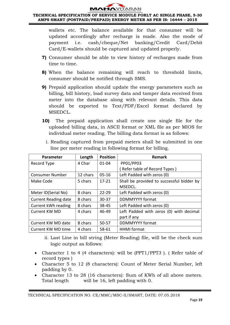


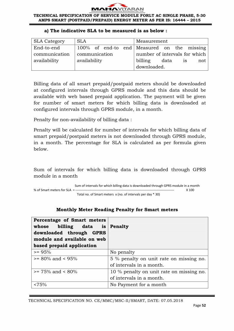


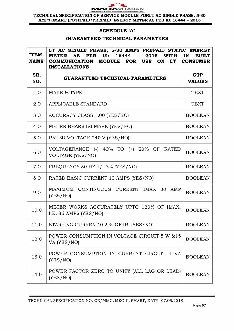


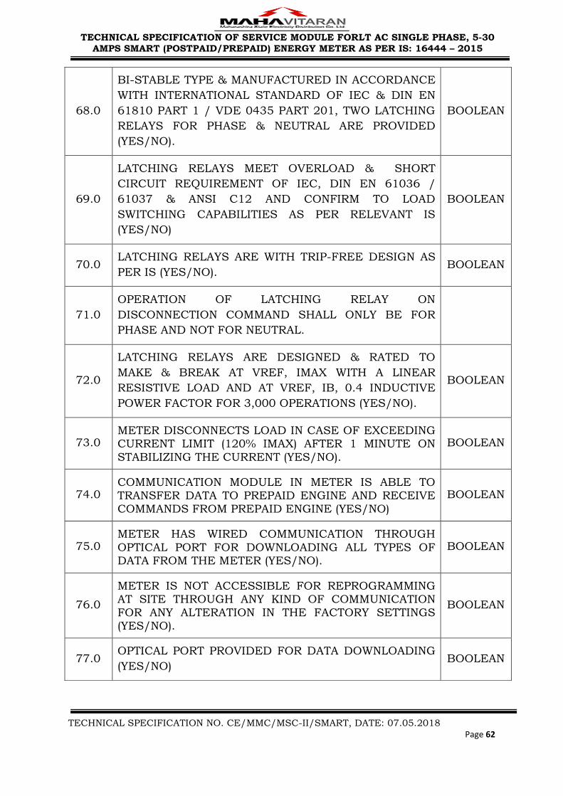


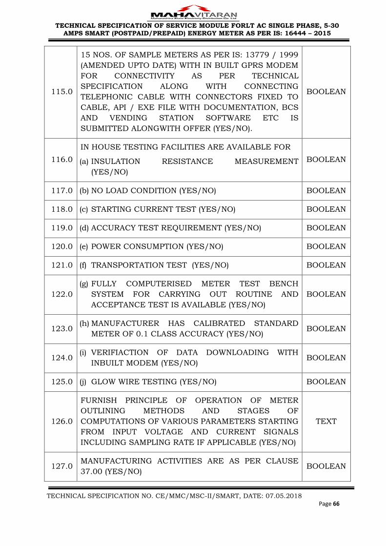


![Technical Specification - University Services | · Web view[System/Application Name] Technical Design Specification Technical Design Specification Template Guideline To aid in the](https://static.documents.pub/doc/80x56/5ae76c407f8b9a08778e4f9f/technical-specification-university-services-viewsystemapplication-name-technical.jpg)