15
page 1 of 15 MAURER Seismic Protection

page 1 of 15
MAURER Seismic Protection

page 2 of 15
Contents
1. Introduction 1.1. General 1.2. General aspects of seismic protection 1.2.1. Protection by energy distribution 1.2.2. Protection by basis isolation and dissipation 2. Bearing elements for basis isolation 2.1. Rubber Bearings 2.1.1. Low damping rubber bearings (LDRB) 2.1.2. High damping rubber bearings (HDRB) 2.1.3. Rubber bearings with lead core 2.2. Sliding bearings 2.2.1. Sliding bearings without recentering (SI) 2.2.2. Sliding isolation pendulum (SIP) - recentering 2.2.3. Double sliding isolation pendulum type D - recentering
3. Hydraulic coupling and damping elements 3.1. Shock transmitter (MSTU) 3.2. Shock transmitter with overload protection (MSTL) 3.3. Hydraulic Damper (MHD) 4. Expansion joints for seismic movements
(type DS / DS-F)
5. Non-linear structural analysis Maurer Söhne Head Office Frankfurter Ring 193, 80807 München / Germany Phone ++49 - 89 - 3 23 94-0 Fax ++49 – 89 - 3 23 94-3 06 [email protected] www.maurer-soehne.de
Seite 3 3 4 4 5 7 7 7 7 8 8 9 10 10 11 11 12 13 14 15
page 3 of 15
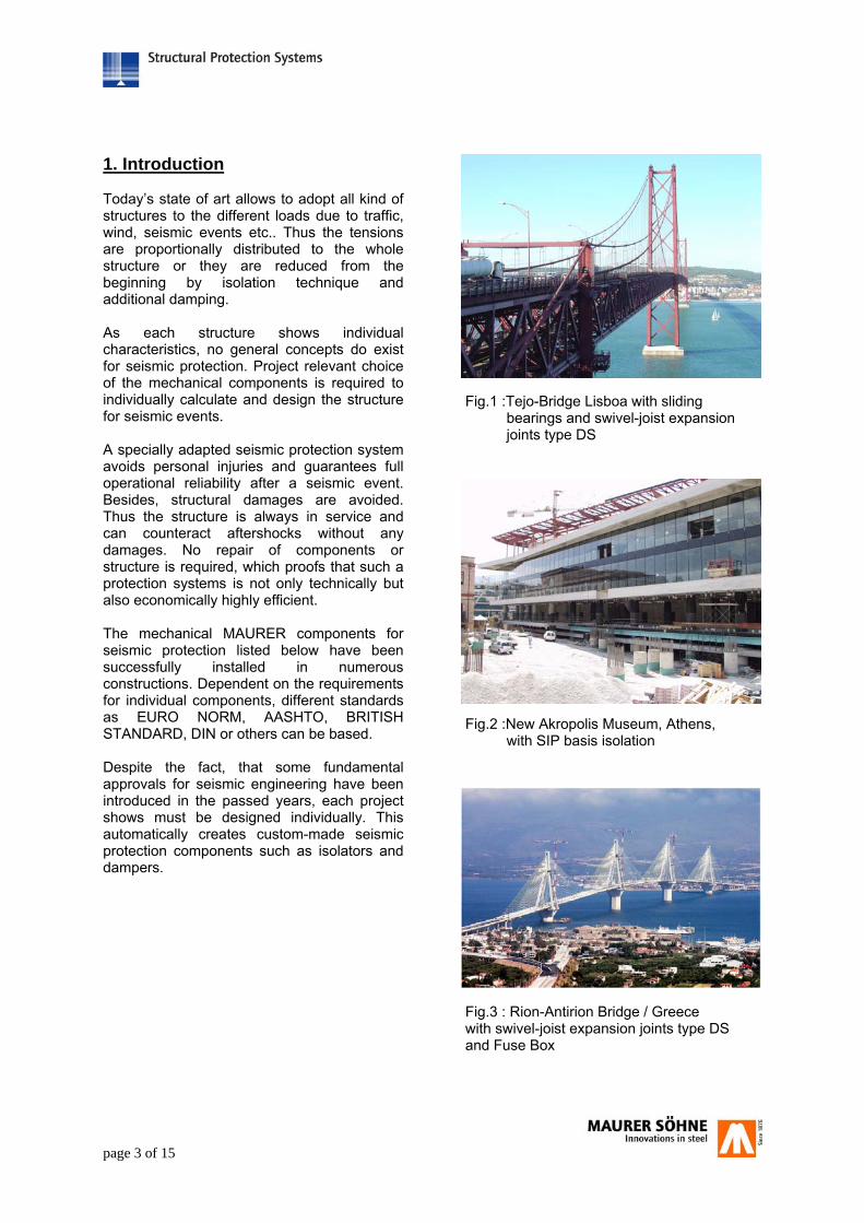
1. Introduction Today’s state of art allows to adopt all kind of structures to the different loads due to traffic, wind, seismic events etc.. Thus the tensions are proportionally distributed to the whole structure or they are reduced from the beginning by isolation technique and additional damping. As each structure shows individual characteristics, no general concepts do exist for seismic protection. Project relevant choice of the mechanical components is required to individually calculate and design the structure for seismic events. A specially adapted seismic protection system avoids personal injuries and guarantees full operational reliability after a seismic event. Besides, structural damages are avoided. Thus the structure is always in service and can counteract aftershocks without any damages. No repair of components or structure is required, which proofs that such a protection systems is not only technically but also economically highly efficient. The mechanical MAURER components for seismic protection listed below have been successfully installed in numerous constructions. Dependent on the requirements for individual components, different standards as EURO NORM, AASHTO, BRITISH STANDARD, DIN or others can be based. Despite the fact, that some fundamental approvals for seismic engineering have been introduced in the passed years, each project shows must be designed individually. This automatically creates custom-made seismic protection components such as isolators and dampers.
Fig.1 :Tejo-Bridge Lisboa with sliding bearings and swivel-joist expansion joints type DS
Fig.2 :New Akropolis Museum, Athens, with SIP basis isolation
Fig.3 : Rion-Antirion Bridge / Greece with swivel-joist expansion joints type DS and Fuse Box

page 4 of 15
1.2.General aspects of seismic protection 1.2.1 Protection by energy distribution Energy distribution means, that the seismic energy proceeding from the subsoil is distributed to different structural components and thus significant energy accumulation is avoided. For this, special components, so-called Shock Transmission Units are used, which allow relative movements due to temperature differences and shrinking/creeping during normal service load (fig. 4). Only with seismic effects or other suddenly arising effects due to traffic or similar, MAURER Shock Transmission Units (MSTUs) act as securing devices (fig. 5). The horizontally acting seismic forces due to earthquake or traffic are transmitted to several structural parts, which increases the structural capability to store elastic and also kinetic energy. Simultaneously the structural movements decrease compared to the design without MSTUs. The horizontal forces are thus distributed more or less constantly to the whole construction and even non-uniform structural loads with tension peaks are avoided. Contrary to above mentioned assumption, seismic loads and deformations are not the cause rather the effect of the short dynamic appearance of huge stored energy from the subsoil. For a more efficient effect of the protection system, it must obey the seismic character. The pure distribution of seismic energy to different structural parts is usually not sufficient to adequately protect the structure. The seismic energy still reaches and goes through the structure without being weakened, as each axis provided with a MSTU becomes a fixed axis in case of seismic event (fig. 6), so that the complete structure is accelerated.
Fig. 4: Bearing system with MSTUs
Longitudinal direction of bridge
Fig. 5: Bridge during service load with inactive MSTU`s
MSTU
Fig. 6: Bridge with active MSTU´s during seismic event
structural deformation
seismic stimulation

page 5 of 15
1.2.2. Protection by basis isolation and dissipation Basis isolation and dissipation result in decreasing the energy applied to the system and the transformation from energy to heat. This is also designated as “energy approach”, which especially takes into account the energy character of a seismic event. Applying this systems means prevention of cost-intensive structural stiffening and attainment of maximum protection of persons and structure. Two statements are applied at the same time: Seismic isolation: The superstructure respectively the structure is separated from the subsoil. This method, also called seismic isolation, automatically limits the energy effecting the structure respectively reduces the same considerably. As a result the natural structural period (periodical displacement) is increased, which causes a considerable reduction of the structural acceleration during seismic event (fig. 7). Depending on the installed type of isolator, the isolators do not only guarantee the vertical load transmission but also the restoring capacity during and after a seismic event. Restoring means, that the superstructure, which has been displaced from neutral position during the seismic event, is automatically recentered. Thus, accumulated structural displacements in one direction are avoided! Energy dissipation: By means of passive energy dissipation (transformation of energy into heat) the remaining energy, which effects the structure due to isolators, is effectively dissipated by additional damping elements. Thus the already dissipated energy does no more effect the complete structure (fig. 8). This energy reducing method, which combines seismic isolation with energy dissipation, produces the best possible seismic protection. Summarized the following demands on basis isolation have to be applied: ●vertical load transmission ●free movement in all directions ●damping of structural vibrations ●recentering in neutral position
period [s]
acceleration [a]
2 1
acceleration of a non- isolated structure
acceleration of isolated structure
Fig. 7: Characteristic response spectrum of a bridge
periodical displacement
reduction of a
Fig.9: possible arrangement of dampers
no damages
seismic stimulation
no structural deformations
damper
isolators
Fig. 8: possible arrangement of isolators with damping effect
= multidirectional seismic isolator with restoring force = damper

page 6 of 15
If flexible piles do exist – e.g. high piles in the middle of a bridge – the restoring force for the seismic protection system and the superstructure is guaranteed by the flexibility of the piles, which act as rod-shaped springs. In that case, longitudinally fixed bearings are installed on the flexible piles (fig. 10). Fixed and longitudinally fixed bearings do not allow any relative movements between pile and superstructure. Flexible piles are bending on a seismic event, thus creating restoring forces. At the same time, this system isolates the superstructure at least mostly from the subsoil. A slight disadvantage of this system is the missing isolation in lateral bridge direction, so that the resulting lateral forces have to be transmitted by the bridge bearings. Particularly with huge structures (bridges with a length exceeding 1500m) a complete isolation often is not practicable. Thus, this solution does not offer the full seismic isolation, however guarantees a significant energy reduction and a pleasing force distribution within the structure. Moreover, this solution is highly qualified retrofit of existing bridges. The method of energy reduction makes use of isolation advantages and energy dissipation, so that it is the technically most effective solution with high safety reserves at extremely high efficiency. With this concept the building is protected such that also in case of aftershocks the protection system is still operational. To adjust movements of the superstructure at the abutments and to bridge the gap, earthquake-fit expansion joints are installed (fig. 12). These expansion joints must adjust quickly arising, alternating relative movements in all directions (x, y and z) without being damaged or damaging the structure.
Fig.12: Movements at the expansion joint
Fig. 10: Bearing system with dampers and flexible piles
Fig 11: Bridge with protection system based on fig. 10
seismic stimulation
sliding bearing
flexible piles with fixed bearings
Dehnfuge
DeckWider-lager
Lager

page 7 of 15
2. Bearing elements for basis isolation 2.1. Elastomeric bearings 2.1.1. Elastomeric bearings Elastomeric isolators consist of several superposed steel sheets, which are connected by a special elastomer (fig. 13). The isolators transmit the vertical loads from the structure by simultaneous rotation and automaticl re-centering, which is dependent on the height of the elastomer and its shear force. Last-mentioned is between 0.6 and 1.0 N/mm². Damping of the elastomeric isolators totals to 6 – 15 %, dependent on demands, and can thus individually be adjusted to each structure. However in many cases no sufficient structural protection and energy dissipation can be obtained in case of a seismic event, using only this type of isolator. A combination with viscous dampers is technically and economically required. Depending on the system demands as e.g. floating bearing system, partially floating bearing system or securing by flexible piles, besides isolators movable on all sides also fixed bearings are used to obtain a special function for service and seismic loads. Thus the choice of the appropriate type of bearing resp. isolator depends on the structural demands, the loads, the horizontal stiffness criterion and the required energy dissipation. 2.1.2. High damping elastomeric bearings High damping elastomeric bearings include an elastomer with high damping characteristics. These “High Damping Rubber (HDR)” show an improved contact area between elastomeric molecule and filling material, which leads to higher damping rates ζ = 0.10 to 0.20, compared with “Low Damping Rubber (LDR)” ζ= 0.04 to 0.06 and thus results in a more complete hysteresis.
Fig.13: Elastomeric bearing with lead core
Fig.14: Elastomeric bearing without lead core
Ohne Bleikern
Mit Bleikern:
Fig.15: Hysteresis of an elastomeric bearing with/without lead core
page 8 of 15
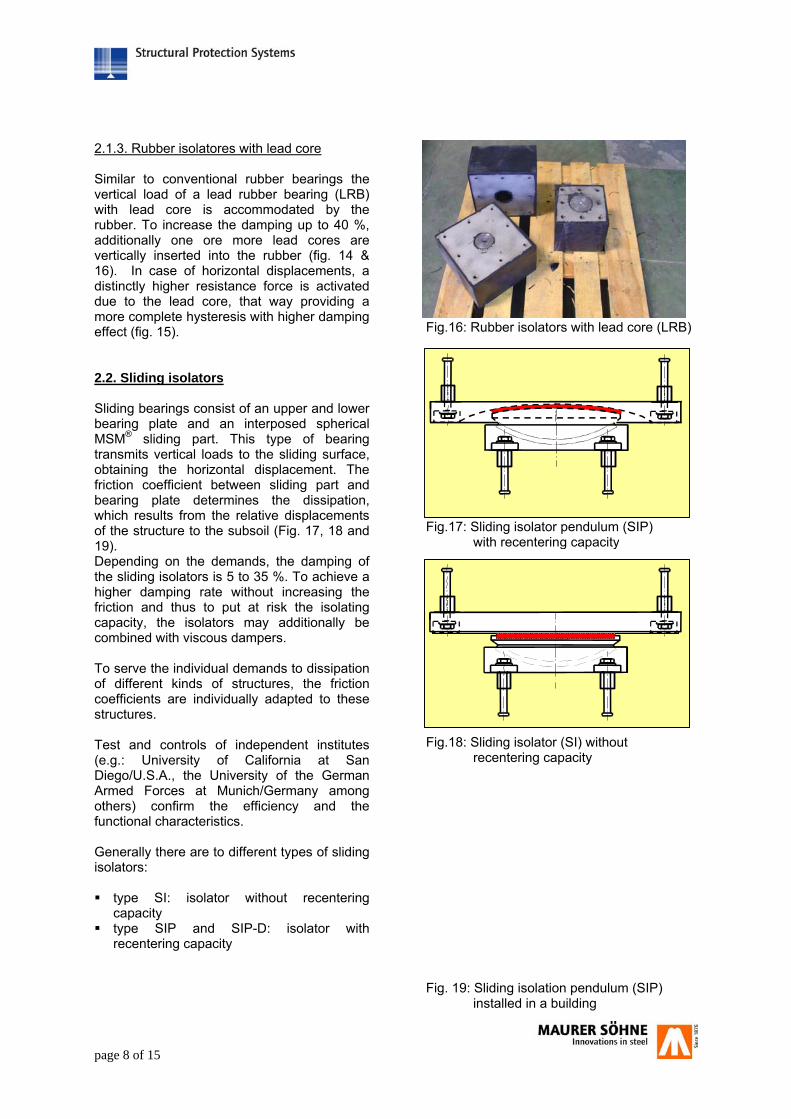
2.1.3. Rubber isolatores with lead core Similar to conventional rubber bearings the vertical load of a lead rubber bearing (LRB) with lead core is accommodated by the rubber. To increase the damping up to 40 %, additionally one ore more lead cores are vertically inserted into the rubber (fig. 14 & 16). In case of horizontal displacements, a distinctly higher resistance force is activated due to the lead core, that way providing a more complete hysteresis with higher damping effect (fig. 15). 2.2. Sliding isolators Sliding bearings consist of an upper and lower bearing plate and an interposed spherical MSM® sliding part. This type of bearing transmits vertical loads to the sliding surface, obtaining the horizontal displacement. The friction coefficient between sliding part and bearing plate determines the dissipation, which results from the relative displacements of the structure to the subsoil (Fig. 17, 18 and 19). Depending on the demands, the damping of the sliding isolators is 5 to 35 %. To achieve a higher damping rate without increasing the friction and thus to put at risk the isolating capacity, the isolators may additionally be combined with viscous dampers. To serve the individual demands to dissipation of different kinds of structures, the friction coefficients are individually adapted to these structures. Test and controls of independent institutes (e.g.: University of California at San Diego/U.S.A., the University of the German Armed Forces at Munich/Germany among others) confirm the efficiency and the functional characteristics. Generally there are to different types of sliding isolators: type SI: isolator without recentering
capacity type SIP and SIP-D: isolator with
recentering capacity
Fig.16: Rubber isolators with lead core (LRB)
Fig.17: Sliding isolator pendulum (SIP) with recentering capacity
Fig.18: Sliding isolator (SI) without recentering capacity
Fig. 19: Sliding isolation pendulum (SIP) installed in a building

page 9 of 15
2.2.1 Sliding isolators without recentering capacity (SI) Sliding isolators type SI (= sliding isolator) without recentering capacity consist of a horizontal sliding surface, allowing a displacement and thus dissipating energy by means of defined friction between both sliding components MSM® and stainless steel (fig. 20 & 21). The hysteresis curve of fig. 22 shows the typical course of friction force in dependence on the displacement direction, compared with a sliding isolation pendulum with recentering capacity. As, apparent from the hysteresis curve, no elastic energy is created, thus no restoring force exists within the system. To yet achieve resetting, elastic components must be installed, which produce the relevant counteracting force for the respective displacement, which is necessary for recentering. Depending on the design of the super- and substructure, also an arrangement of an isolator turned about 180° (“upside down”) is possible.
Fig.20 : Sliding isolator type SI
Fig.22 : Hysteresis curves of sliding isolatorsand sliding isolation pendula
Fig.21 : SI - sliding isolator for 130,000 kN load (SLS)
s
F
SI
SIP und SIP-D

page 10 of 15
2.2.2 Sliding isolation pendulum with recentering capacity (SIP) Compared with sliding isolators, sliding isolation pendula (SIPs) with recentering capacity have a concave sliding plate (fig. 24). Due to geometry, each horizontal displacement results in a vertical movement of the isolator. Thus a part of kinetic energy is transformed into potential energy. The potential energy, stored by the superstructure, which has been pushed to the top, automatically results in recentering the bearing into neutral position This restoring force can also be taken from the hysteresis curve for types SIP and SIP-D (fig. 23.). The sliding isolation pendula are excellently suited to isolate the structure from the subsoil. They remain horizontally flexible, dissipate energy and recenter the superstructure into neutral position. 2.2.3 Double sliding isolation pendula type D with recentering capacity (SIP-D) In case of a type D sliding isolation pendula with recentering capacity the sliding part moves between two symmetrical concave bearing plates (fig. 23). With the same diameter, the type D bearings perform double the displacement as simple sliding isolation pendula. Thus the type D isolators with movements +/-300mm frequently guarantee a more efficient solution. Also the outline of this type of isolator becomes smaller, as well as the eccentricities are shared to super- and substructure.
Fig. 23 :Characteristic hysteresis curve of asliding isolation pendulum (SIP)
Fig.22 : Sketch of a sliding isolation pendulum (SIP)
Fig.23 : Double sliding isolation pendulum (SIP-D)
Keff = effektive
Verschiebung
Kraft
KSI = Isolatorsteifigkeitµ W = Reibkraft
Ki = initiale Steifigkeit
D
F
Keff = effektive
Verschiebung
Kraft
KSI = Isolatorsteifigkeitµ W = Reibkraft
Ki = initiale Steifigkeit
D
F

page 11 of 15
3. Hydraulic coupling and damping elements 3.1 Shock Transmitter MAURER Shock Transmission Units (MSTUs) are maintenance-free, hydraulic devices, to rigidly connect structures, which are moveable relatively to one another, in case of suddenly arising dynamical shocks as e.g. earthquakes, brake forces etc.. MSTUs are installed separately into the structure or combined with bridge bearings. In specialist literature also terms like Lock-Up Device (LUD), Rigid Connection Device (RCD), Seismic Connectors, Buffers or similar can be found for these mechanical devices. Dependent on the motion speed, the shock transmitter reacts with a corresponding force (fig. 26). Very slow movements e.g. from temperature, shrinkage/creeping etc. do not result in significant forces. With these forces the fluid moves within the hydraulic cylinder without creating worth mentioning forces. If sudden acceleration between the connected structural elements result e.g. due to seismic or brake forces, which lead to motion speeds with more than 0.1 mm/s, the shock transmitter reacts with a force(fig. 26), that means, no movements between the connected structural elements are allowed. A rigid connection between the structural elements is thus created. With this quick respectively sudden movements, the hydralic fluid cannot move from one side of the cylinder to the other, so that the MSTU blocks movements.
Both functional characteristics are: No worth mentioning force (max. 10 % of the design force) resulting from movements due to shrinkage/creeping and changes in temperature. Sudden blockade respectively formation of resisting force (= design force = Fn) for suddenly arising movements due to traffic, earthquake or similar.
Fig.25: Shock-Transmitter
Fig. 24: Shock-Transmitter (MSTU)
Seal-system Fluid chamber Orifice
piston
[F]
[v]
A) Service- B) Erdbeben lastfall
0,1 mm/s
Fig. 26: force [F] - speed [v] – graph for MSTU
Fn
[F]
[s]
[F]
[s]
A) Servicelastfall B) Erdbeben
Fn
Fig. 27: force [F] - direction [s] – graph for MSTU

page 12 of 15
3.2. Shock Transmitter with overload protection (MSTL) Shock transmitter can additionally be equipped with a force limiter, which reduces the maximum limit force (Fl) to an individually determinable maximum value. Usually this value is calculated insignificantly above the nominal shock force (Fn) or can be stipulated individually. If the maximum value of the force is obtained due to excessive energy supply, an „intelligent“ control mechanism allows a movement of the MSTL (fig. 28 & 29). The response force is always kept constantly at the in advance determined maximum level, whereby the motion speed does not play part. If the energy supply falls below a certain level, the movement almost stops. This load limiting function is of great advantage for the planner, as the maximum force of the shock transmitter is exactly known. Thus the structure can exactly be designed as to this force, resulting in considerably lower constructional costs and significantly increased structural safety. The MSTL guarantees that, compared with the MSTU, all shock transmitters are stressed evenly and simultaneously, or rather that neither the structure nor the component is damaged due to different operational behaviour of the shock transmitters at different parts of the structure. During the „overload“ above maximum load,, the MSTL moves and thus dissipates energy. This energy quantity however turns out less than in case of pure dampers (MHD), as the MSTL is not designed for energy dissipation, but primarily for force limiting. So, if moreover an optimum energy dissipation is required, dampers of type MHD must be installed.
The three functional characteristics are: A) No worth mentioning response force (max. 10 % of the design force) resulting from movements due to shrinkage/creeping and changes in temperature. B) Sudden blockade respectively formation of resisting force (= design force = Fn) for suddenly arising movements due to traffic, earthquake or similar. C) Limitation of the maximum response force (= limitation force = Fl) in case of to much energy input, which would cause an undefined great response force.
Fig. 28 :force [F] - speed [v] - graph
Fig. 29 :force [F]- distance [s]- graph
[v]
[F]
A) Service- B) C) Erdbeben lastfall
0,1 mm/s 1 mm/s
Fl Fn
A) Servicelastfall B+C) Erdbeben
[F]
[s]
[F]
[s]
Fl Fn
Fl Fn
Fig. 30: Shock Transmitter with force limiter (MSTL)
page 13 of 15
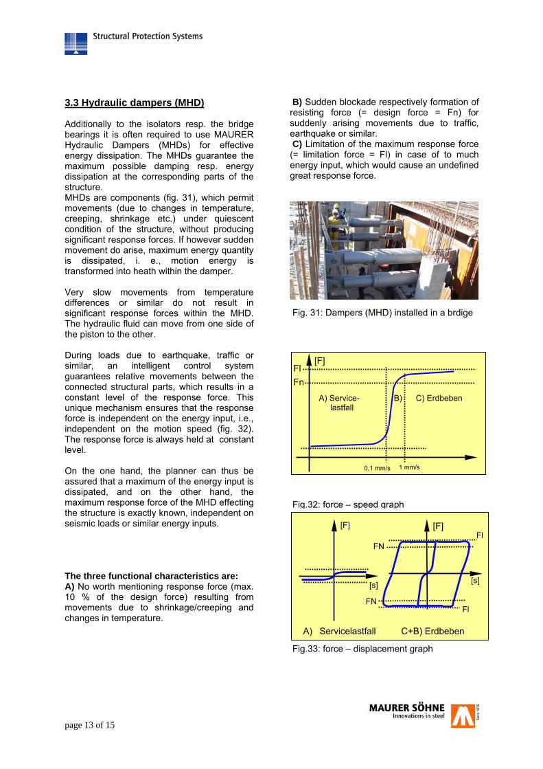
3.3 Hydraulic dampers (MHD) Additionally to the isolators resp. the bridge bearings it is often required to use MAURER Hydraulic Dampers (MHDs) for effective energy dissipation. The MHDs guarantee the maximum possible damping resp. energy dissipation at the corresponding parts of the structure. MHDs are components (fig. 31), which permit movements (due to changes in temperature, creeping, shrinkage etc.) under quiescent condition of the structure, without producing significant response forces. If however sudden movement do arise, maximum energy quantity is dissipated, i. e., motion energy is transformed into heath within the damper. Very slow movements from temperature differences or similar do not result in significant response forces within the MHD. The hydraulic fluid can move from one side of the piston to the other. During loads due to earthquake, traffic or similar, an intelligent control system guarantees relative movements between the connected structural parts, which results in a constant level of the response force. This unique mechanism ensures that the response force is independent on the energy input, i.e., independent on the motion speed (fig. 32). The response force is always held at constant level. On the one hand, the planner can thus be assured that a maximum of the energy input is dissipated, and on the other hand, the maximum response force of the MHD effecting the structure is exactly known, independent on seismic loads or similar energy inputs. The three functional characteristics are: A) No worth mentioning response force (max. 10 % of the design force) resulting from movements due to shrinkage/creeping and changes in temperature.
B) Sudden blockade respectively formation of resisting force (= design force = Fn) for suddenly arising movements due to traffic, earthquake or similar. C) Limitation of the maximum response force (= limitation force = Fl) in case of to much energy input, which would cause an undefined great response force.
Fig.32: force – speed graph
Fig.33: force – displacement graph
[F]
A) Service- B) C) Erdbeben lastfall
0,1 mm/s 1 mm/s
Fl Fn
[F]
[s]
[F]
[s]
Fl
Fl
A) Servicelastfall C+B) Erdbeben
FN
FN
Fig. 31: Dampers (MHD) installed in a brdige

page 14 of 15
4. Seismic expansion joints Earthquakes can generate structural movements which are considerably larger, many times quicker and much more complex in their direction than those under normal operational conditions. That is why applications of that kind require a special design of the expansion joint. Swivel joist expansion joints type DS (fig. 34) are especially designed for use in seismic regions. The conventional requirements set to the operating conditions are irrelevant during seismic action. Of particular importance, however are as follows: maintenance of serviceability of the
structure after the earthquake, at least for emergency vehicles, protection of the structure from impact
damages caused by closing movements during the earthquake as well as prevention of an open gap due to too large
opening movements. Employing a long and superior performance history in normal service conditions, the Swivel-Joist Expansion Joint had been further enhanced such as to also fulfil the aforementioned seismic requirements. When the expansion joint or the structural gap closes, there might result damages or even breakdown of the structure. For better protection of the bridge structure, a so-called "fuse box" has been developed (fig. 35). If the expansion joint should close in case of a quake, the breaking point will be activated. The anchorage system disengages alongside a ramp according to a defined failure load and will return to its original position as soon as the quake is over. The breaking point is repairable with less effort.
Fig. 34: DS – Swivel joist expansion joint
Fig. 35: functional principle of a Fuse box at a swivel joist expansion joint
page 15 of 15
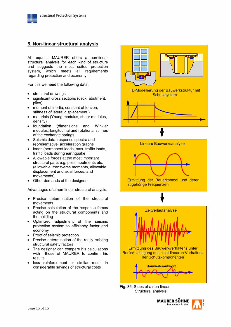
5. Non-linear structural analysis At request, MAURER offers a non-linear structural analysis for each kind of structure and suggests the most suited protection system, which meets all requirements regarding protection and economy. For this we need the following data: • structural drawings • significant cross sections (deck, abutment,
piles) • moment of inertia, constant of torsion,
stiffness of lateral displacement ) • materials (Young modulus, shear modulus,
density) • foundation (dimensions and Winkler
modulus, longitudinal and rotational stiffnes of the exchange springs.
• Seismic data: response spectra and representative acceleration graphs
• loads (permanent loads, max. traffic loads, traffic loads during earthquake
• Allowable forces at the most important structural parts e.g. piles, abutments etc. (allowable transverse moments, allowable displacement and axial forces, and movements)
• Other demands of the designer Advantages of a non-linear structural analysis: ● Precise determination of the structural
movements • Precise calculation of the response forces
acting on the structural components and the building
• Optimized adjustment of the seismic protection system to efficiency factor and economy
• Proof of seismic protection • Precise determination of the really existing
structural safety factors • The designer can compare his calculations
with those of MAURER to confirm his results
• less reinforcement or similar result in considerable savings of structural costs
Fig. 36: Steps of a non-linear Structural analysis
Lineare Bauwerksanalyse
Ermittlung der Bauerksmodi und derenzugehörige Frequenzen
FE-Modellierung der Bauwerkstruktur mit Schutzsystem
Zeitverlaufanalyse
Ermittlung des Bauwerkverhaltens unter Berücksichtigung des nicht-linearen Verhaltens
der Schutzkomponenten
Bauwerksantwort


