Maximizing Aggregate Throughput in 802.11 Mesh Networks with Physical Carrier Sensing and Two-Radio Multi-Channel Clustering Jing Zhu 1 , Sumit Roy 1 , Xingang Guo 2 , and W. Steven Conner 2 {zhuj, roy}@ee.washington.edu {xingang.guo, w.steven.conner}@intel.com 1 Department of Electrial Engineering, University of Washington, Seattle, WA, U.S.A. 2 Communications Technology Lab, Intel Corporation, Hillsboro, OR, U.S.A. Abstract— Spatial reuse in a mesh network allows multiple communications to proceed simultaneously, hence proportion- ally improving the overall network throughput. To maximize spatial reuse, the MAC protocol must enable simultaneous co- channel transmitters to maintain a separation distance that is sufficient to avoid interference. Within that distance, a set of orthogonal channels is employed by different links. This paper demonstrates that physical carrier sensing en- hanced with a tunable sensing threshold is effective at avoid- ing co-channel interference in 802.11 mesh (static + multi- hop) networks. Moreover, for multi-channel mesh networks, an architecture for channel clustering based on two-radio nodes is proposed. Distributed clustering is achieved using the Highest-Connectivity Cluster (HCC) algorithm. All inter- cluster communications are performed on a common channel using the default radio, while intra-cluster communications use the secondary radio with channel selection based on a new Minimum Interference Channel Selection (MIX) algorithm that minimizes the co-channel interference (CCI). Backward compatibility is guaranteed by allowing legacy single-channel devices to connect to the new two-radio devices through the common default radio. Simulation results for large-scale 802.11b and 802.11a networks demonstrate the significant improvement in one-hop aggregate throughput. Specifically, the new two-radio multi-channel mesh solution increases the aggregate throughput by more than twice w.r.t. the traditional single-radio single-channel mesh. I. I NTRODUCTION The past few years have witnessed the rapid proliferation of wireless LANs in various environments: home, enterprize and hotspot. The need for higher data rates and improved coverage has led to multi-cell networks (particularly for business and hotspot scenarios but also for clusters of homes/apartments) where each cell is served by its own access point (AP). Currently, all APs are directly connected (typically via Ethernet) to an Internet gateway. Therefore, the cost and time of deploying a large scale WLAN network dramatically increases as the network expands. A possible solution to this problem is connecting APs wirelessly to form a (static) multi-hop .11 (mesh) network (see Fig.1). The high interest in such an approach is indicated not only by the newly formed Mesh Task Group within IEEE 802.11 but also mesh solutions offered by several companies [2], [3], [4] to list a few. Such a future wireless AP-AP mesh network requires both protocol and architectural extensions to current .11 networks for which there does not exist any standardized inter-AP connectivity protocol. Furthermore, since the wireless channel is a broadcast (shared) medium with bandwidth limitations, the aggregate throughput of such a wireless inter-AP mesh is governed by the following key network parameters: K: number of concurrent active links per channel (degree of co-channel spatial reuse); W: max. data rate per channel; N: number of orthogonal channels within a reuse distance This paper looks at approaches to maximize K as well as utilizing N to maximize the aggregate throughput of a wireless mesh network. In [7], spatial reuse was demonstrated to depend on various characteristics of the network, including the type of radio, network topology, channel quality requirements and signal propagation environment. For a given network configuration, there exists a minimum separation distance such that when simultaneous transmitters are separated by that distance, the maximum number of simultaneous transmissions can be accommodated, allowing maximum network throughput to be achieved. However, achieving maximum spatial reuse would require an ideal MAC proto- col that schedules communication to maintain the optimal transmitter separation distance (to minimize interference) in a fully distributed manner. Nodes in a IEEE 802.11 WLAN network seeking channel access use carrier sensing to determine if the medium is available before transmitting to avoid packet collision [1]. Two types of carrier sensing are supported by the 802.11 MAC: mandatory physical carrier sensing that monitors the RF energy level in the air and optional virtual carrier sens- ing that uses the Request-to-Send/Clear-to-Send (RTS/CTS) handshake to ensure that the air medium at the receiver is reserved prior to data packet transmission. Virtual carrier sensing was designed to avoid the well-known hidden termi- nal problem [11], where it is assumed that physical carrier
Transcript
Maximizing Aggregate Throughput in 802.11Mesh Networks with Physical Carrier Sensing and
Two-Radio Multi-Channel ClusteringJing Zhu1, Sumit Roy1, Xingang Guo2, and W. Steven Conner2
1 Department of Electrial Engineering, University of Washington, Seattle, WA, U.S.A.2 Communications Technology Lab, Intel Corporation, Hillsboro, OR, U.S.A.
Abstract— Spatial reuse in a mesh network allows multiplecommunications to proceed simultaneously, hence proportion-ally improving the overall network throughput. To maximizespatial reuse, the MAC protocol must enable simultaneous co-channel transmitters to maintain a separation distance thatis sufficient to avoid interference. Within that distance, aset of orthogonal channels is employed by different links.This paper demonstrates that physical carrier sensing en-hanced with a tunable sensing threshold is effective at avoid-ing co-channel interference in 802.11 mesh (static + multi-hop) networks. Moreover, for multi-channel mesh networks,an architecture for channel clustering based on two-radionodes is proposed. Distributed clustering is achieved usingthe Highest-Connectivity Cluster (HCC) algorithm. All inter-cluster communications are performed on a common channelusing the default radio, while intra-cluster communications usethe secondary radio with channel selection based on a newMinimum Interference Channel Selection (MIX) algorithmthat minimizes the co-channel interference (CCI). Backwardcompatibility is guaranteed by allowing legacy single-channeldevices to connect to the new two-radio devices throughthe common default radio. Simulation results for large-scale802.11b and 802.11a networks demonstrate the significantimprovement in one-hop aggregate throughput. Specifically,the new two-radio multi-channel mesh solution increases theaggregate throughput by more than twice w.r.t. the traditionalsingle-radio single-channel mesh.
I. INTRODUCTION
The past few years have witnessed the rapid proliferationof wireless LANs in various environments: home, enterprizeand hotspot. The need for higher data rates and improvedcoverage has led to multi-cell networks (particularly forbusiness and hotspot scenarios but also for clusters ofhomes/apartments) where each cell is served by its ownaccess point (AP). Currently, all APs are directly connected(typically via Ethernet) to an Internet gateway. Therefore,the cost and time of deploying a large scale WLAN networkdramatically increases as the network expands. A possiblesolution to this problem is connecting APs wirelessly toform a (static) multi-hop .11 (mesh) network (see Fig.1).The high interest in such an approach is indicated not onlyby the newly formed Mesh Task Group within IEEE 802.11but also mesh solutions offered by several companies [2],
[3], [4] to list a few. Such a future wireless AP-AP meshnetwork requires both protocol and architectural extensionsto current .11 networks for which there does not exist anystandardized inter-AP connectivity protocol. Furthermore,since the wireless channel is a broadcast (shared) mediumwith bandwidth limitations, the aggregate throughput ofsuch a wireless inter-AP mesh is governed by the followingkey network parameters:
K: number of concurrent active links per channel(degree of co-channel spatial reuse);
W: max. data rate per channel;N: number of orthogonal channels within a reuse
distance
This paper looks at approaches to maximize K as wellas utilizing N to maximize the aggregate throughput of awireless mesh network.
In [7], spatial reuse was demonstrated to depend onvarious characteristics of the network, including the typeof radio, network topology, channel quality requirementsand signal propagation environment. For a given networkconfiguration, there exists a minimum separation distancesuch that when simultaneous transmitters are separatedby that distance, the maximum number of simultaneoustransmissions can be accommodated, allowing maximumnetwork throughput to be achieved. However, achievingmaximum spatial reuse would require an ideal MAC proto-col that schedules communication to maintain the optimaltransmitter separation distance (to minimize interference) ina fully distributed manner.
Nodes in a IEEE 802.11 WLAN network seeking channelaccess use carrier sensing to determine if the medium isavailable before transmitting to avoid packet collision [1].Two types of carrier sensing are supported by the 802.11MAC: mandatory physical carrier sensing that monitors theRF energy level in the air and optional virtual carrier sens-ing that uses the Request-to-Send/Clear-to-Send (RTS/CTS)handshake to ensure that the air medium at the receiver isreserved prior to data packet transmission. Virtual carriersensing was designed to avoid the well-known hidden termi-nal problem [11], where it is assumed that physical carrier
sensing at a transmitter is not sufficient to avoid interferenceat a receiver. However, it has been shown that virtual carriersensing via RTS/CTS in fact suffers from fundamentallimitations in avoiding interference from hidden terminals[12]. In 802.11, this can be attributed to lack of properdesign of the physical carrier sensing mechanism. In thispaper we demonstrate that, when properly tuned, physicalcarrier sensing is effective at avoiding interference in amulti-hop wireless mesh network without the use of virtualcarrier sensing.
Physical carrier sensing allows a station to assess thechannel condition before transmitting to make sure thatno interference can occur. A node samples the energy onthe channel and initiates channel access only if the readingis below the carrier sensing threshold, indicating that anyongoing communication only produces tolerable interferewith the impending transmission. According to RF pathlossmodels, the long-term average received energy at a nodedecays with distance from a transmitter. Hence the car-rier sensing threshold effectively determines the minimumallowed distance between simultaneous transmitters. Sincethe optimal distance depends on various network properties,the carrier sensing threshold should be tuned to currentnetwork conditions. However, many of today’s 802.11 MACimplementations use a static threshold, or do not allow thethreshold to be independently tunable [16]. As a result,physical carrier sensing often leads transmitters to be eithertoo conservative or too aggressive when using the wirelesschannel.
In this work, we assume a tunable carrier sensing thresh-old and illustrate how to derive the appropriate carrier sens-ing threshold from relevant network characteristics via anal-ysis. Furthermore, we propose an estimation-based adaptivephysical carrier sensing scheme to automatically tune thethreshold to a near-optimal value. We present OPNETsimulation results for two regular network topologies (chainand grid) to validate the theoretical optimal PCS thresh-old. Our results further show that by tuning the physicalcarrier sensing threshold, without requiring virtual carriersensing, the overall network throughput can be improvedsignificantly compared to that of the legacy 802.11 MAC.The increased throughput can approach approximately 90%of the theoretical upper-bound predicted by spatial reusemodels in a large chain. Simulation results also demonstratethe effectiveness of the estimation-based adaptive physicalcarriers sensing scheme in networks with dynamic topologyand heterogeneous links.
We note that performance improvement of 802.11 net-works based on enhancement to various aspects of the802.11 MAC protocol has been the subject of recent work[10] [14]. For any given environment, optimizing networkperformance must be a careful combination of approachesaddressing multiple aspects of network performance (e.g.throughput, fairness, etc.) which is beyond the scope of thiswork. We focus here specifically on leveraging the spatialreuse of mesh networks to enhance the throughput throughphysical carrier sensing, which is an essential requirementfor achieving optimal aggregate throughput in a dense
wireless network.
Fig. 1. Wireless AP-to-AP mesh Networks
Communication between nodes on the AP-mesh canshare a single channel or use multiple narrower-band chan-nels. This can be implemented readily using a single-radionetwork (all nodes have only one radio interface) thatsuggests the need for a single wideband shared channel forthe entire AP-mesh to support many simultaneous transmis-sions. However, this approach has not been adopted by in-dustry standards as yet and lacks hardware implementations1. Using multiple narrower-band channels entails potentiallycomplicated channel assignment schemes to inter-AP links,but has existing hardware support (N=8 in 802.11 a, andN=3 in 802.11 b). Thus our proposed solution is based onusing a 20MHz channel for all inter-AP communicationswhile noting that this is likely to be a throughput bottleneckin situations where the inter-AP (routed) traffic dominates.
Two-radio multi-channel approaches, where each node isequipped with two similar PHY/MAC radio interfaces forAP-AP communication, can effectively exploit the availablemultiple orthogonal channels 2 which is infeasible with aone-radio AP Mesh with multiple narrowband channels. Ina two-radio implementation, each node in the AP-mesh isequipped with two WLAN cards that are used for intra-cell and inter-cell communications, respectively. This willalways provide higher throughput than a single-channelapproach, since intra-AP traffic is now separated from inter-AP traffic made possible by two-radio nodes. Such a multi-radio architecture has been proposed in [27] where thechannel used for any AP-AP link from among the availableset is selected by sending probes to estimate the link round
1Further, proportionally improved MAC efficiency is needed to translateincrease link layer rates to higher MAC throughput.
2Note that each AP also needs a third radio for communications forthe AP-MT link (MT: Mobile Terminal), which must be orthogonal to theAP-AP mesh band to avoid interference. This promotes the use of dual,e.g. .11 a/b, radio interface cards.
trip time (RTT) for the available channels and choosing theone with minimum RTT. Updating the channel allocationis performed periodically every few seconds. While theRTT is a useful indicator of channel load, it is a less-than-adequate metric for estimating interference due tosimultaneous transmissions in a wireless scenario. Thus[27] protocol operates more as a load-balancing schemewhich improves but does not optimize aggregate networkthroughput.
Continuous monitoring of channel quality on all channelsis infeasible with a single radio; two radios per nodeconsiderably simplifies this because this task can be per-formed by one radio while the other is transmitting dataon the currently assigned channel. Suggestions for usingone radio purely as a dedicated control channel and theother for data on all other channels have appeared fortwo-radio architectures [26] [25]; but these lead to lowchannel utilization due to control channel becoming abottleneck, and offers no backward compatibility. Thus inour implementation, both radios are used to support datatransmission. Nonetheless, irrespective of the specifics ofhow the two radios are used, this architecture allows thepossibility of a fully distributed MAC implementation that isdesirable for network robustness. For example, to eliminatethe control channel bottleneck, we propose a new semi-distributed AP-clustering approach. A distributed Highest-Connectivity Cluster (HCC) algorithm [22] is employed todivide the network into AP clusters that are distinguishedby the channel used for intra-cluster communication. Inter-cluster communication is performed using the (default andintra-cluster via the secondary) radio, respectively.
A common channel is used for all inter-cluster communi-cations, and different channels are selected for intra-clustercommunications by using a new Minimum InterferenceChannel Selection (MIX) algorithm. Control or manage-ment traffic uses only the default radio; while the secondaryradio is only for data transmissions. Note that backwardcompatibility is achieved since this architecture allows alegacy single-radio AP to connect to the new two-radio APsthrough the (common) default radio.
Unlike most of other cluster-based networks (e.g. Blue-tooth, UWB) that usually employ a cluster head as acontroller running a centralized MAC, the architecture hereuses clustering to only assign a channel in a distributedmanner for the MAC; the base 802.11 MAC mechanisms areunchanged. Similar to [27], our protocol uses a virtual MACaddress in place of the multiple physical MAC addressesused by two radios so that the higher (routing) layer seesonly a single wireless network interface. Routing betweenthe nodes is based on ad-hoc routing approaches similar tothat in the traditional single-channel, single-radio mesh.
II. RELATED WORK ON .11 MAC ENHANCEMENTS
Interference mitigation has been a well-known challengefor MAC protocols in wireless mesh networks. Much ofthe existing research in this space has focussed on elimi-nating the hidden terminal [11] problem. A virtual carrier
sensing mechanism, implemented through the RTS/CTShandshake, has been adopted by IEEE 802.11 in an attemptto eliminate the hidden terminal problem. However, thishas an underlying assumption that all hidden terminals arewithin transmission range of receivers (allowing them toreceive the RTS or CTS packet successfully). While suchan assumption may be reasonable for single cell WLANs, itis generally not true for multi-cell WLANs and multi-hopmesh networks. Researchers [12] [13] [14] have by nowrecognized that virtual carrier sensing with RTS/CTS doesnot solve the hidden terminal problem effectively for suchnetworks.
It was shown in both [12] and [14] that the interferencerange is a function of T-R separation distance. Dependingon the T-R separation distance, the interference range canbe smaller or larger than the transmission range. If theinterference range is smaller than the transmission range,RTS/CTS can indeed prohibit all the hidden terminals frominterfering with the existing transmission; but some of thenodes that are not capable of interfering are also prohibitedfrom transmitting. Thus, in this configuration RTS/CTS istoo aggressive, resulting in a significant exposed terminalproblem that wastes potential throughput by requiring po-tential transmitters to unnecessarily back off. On the otherhand, if the interference range is larger than the transmissionrange, RTS/CTS can fail to prevent hidden terminals frominterfering with an existing transmission. So RTS/CTS istoo conservative and ineffective in this case.
A technique was suggested in [12] to avoid the conser-vative RTS/CTS scenarios by allowing only the transmitter-receiver pairs with distance shorter than a threshold toperform transmission; the threshold is set such that thecorresponding interference range will not be larger thanthe transmission range. The constraint on T-R separationdistance is imposed by only allowing a node to reply toa RTS packet with a CTS packet when the receive powerof the RTS packet is larger than a threshold, even if theRTS packet is received successfully and the node is idle.This added constraint ensures that RTS/CTS never becomestoo conservative and so the hidden terminal problem isavoided. However, this approach does not address theexposed terminal problem introduced by the aggressiveRTS/CTS. Another disadvantage of such an approach isthat it reduces effective transmission range and thus lowersnetwork connectivity.
Several other techniques attempt to reduce inefficienciesintroduced by exposed terminals. The protocol describedin [10] focuses on the exposed terminal problem directlyby enabling nodes to identify themselves as exposed nodesand opportunistically scheduling concurrent transmissionswhenever possible. While [14] recognizes that RTS/CTScan be either too conservative or too aggressive, it only ad-dresses the problems associated with aggressive RTS/CTS.The authors propose a Distance-Aware Carrier Sensing(DACS) scheme which employs an extra handshake inaddition to RTS/CTS to disseminate one-hop distance in-formation to neighbors so that medium reservation can bemore accurate and spatial reuse can be improved to reduce
the negative impact of exposed terminals.Besides interference, packet collision is another important
factor contributing to the final SINR. However, collisionsdue to simultaneous transmission attempts cannot be reli-ably prevented by using physical carrier sensing alone. Acommon approach to avoiding persistent collisions is ran-dom back-off, e.g the binary exponential backoff algorithmin the 802.11 MAC standard. Recently, there have beenseveral efforts aimed at optimizing the back-off algorithmsand contention window size to minimize collisions [6] [17]etc. While the focus of this paper is on leveraging the spatialreuse of a network to enhance the throughput performancethrough physical carrier sensing, these techniques may besupplemented with the above to simultaneously minimizeinterference and the impact of packet collisions to furtherimprove aggregate throughput in a dense wireless network.
Unlike prior techniques that attempt to avoid interfer-ence through handshake protocols, this paper approachesinterference mitigation from the perspective of leveragingspatial reuse. We believe that the key to the optimal spatialreuse is to maintain the appropriate separation distancebetween simultaneous transmitters. Therefore we focus onenhancing the physical carrier sensing mechanism withtunable sensing threshold for the 802.11 MAC. What wepropose in this paper is a simple and effective methodthat directly redresses some of the issues in virtual carriersensing with RTS/CTS.
The rest of this paper is organized as follows: SectionII presents a basic communication model for interferenceanalysis and exposes the limitations of carrier sensing ascurrently implemented in 802.11 DCF. Section III intro-duces our suggestions for enhanced physical carrier sensingbased on a tunable physical sensing threshold, and demon-strates the resulting throughput improvements for someregular mesh networks topologies. Section IV describesour novel two-radio multi-channel clustering architecture.Section V presents OPNET simulation results showingsignificant performance enhancements obtained from tunedphysical carrier sensing along with new clustered two-radio,multi-channel AP-mesh. Section VI discusses our results inthe context of related work, and Section VII concludes thepaper.
III. MANAGING INTERFERENCE WITH PHYSICAL
CARRIER SENSING (PCS)
In CSMA/CA based wireless networks such as IEEE802.11 networks, a transmitter relies on carrier sensing todetermine if the medium is ‘available’, i.e., has acceptablelevel of interference from ongoing transmissions. A trans-mission is initiated only if the energy level is below thePCS threshold. This section uses common radio propagationmodels to determine the effectiveness of carrier sensingand points out several shortcomings of the carrier sensingtechnique employed in 802.11 MAC protocol.
A. Communication Model
Path loss models are commonly used to describe theaverage received power at a receiver over a wireless medium
[7] [19] as a function of the T-R (transmitter-receiver) radialseparation, d, i.e.,
Prx(d) = Prx(d
d)γ (1)
where γ is the path loss exponent that characterizes the rateof signal degradation with distance in the particular networkenvironment. Prx(d) denotes the signal power at distance dfrom the transmitter and Prx is the signal power measuredat a reference distance d (usually 1 meter).
The aggregate energy at any receive node consists ofdesired signal, interference (from unwanted transmitter(s))and background noise. A 802.11 node can receive a packetwith high probability of success in additive noise only if thereceived signal strength is greater than a threshold (denotedby PR, i.e. reception sensitivity); and equivalent conditionin the presence of interference is that the received Signal-Interference and Noise-Ratio (SINR) exceeds a thresholddenoted by S0; i.e.,{
Prx(d) ≥ PRPrx(d)
PN +∑
iPrx(di)
≥ S0, (2)
where PN is the background noise power, and Prx(di)denotes the power of interference source i at distance d i
from the receiver. 802.11 networks support multiple datarates, and a higher data rate requires a higher S0.
B. Terminologies
Eq.2 provides constraints on the receive power as well asthe SINR at detector input for successful detection. In theabsence of any interference, the receive sensitivity PR is setto satisfy PR/PN > S0; this determines the transmissionrange or the maximum distance for successful reception inadditive noise only. It is clear that the actual SINR perceivedvia PCS at a receive node will vary due to the presence ofinterference from ongoing transmissions.
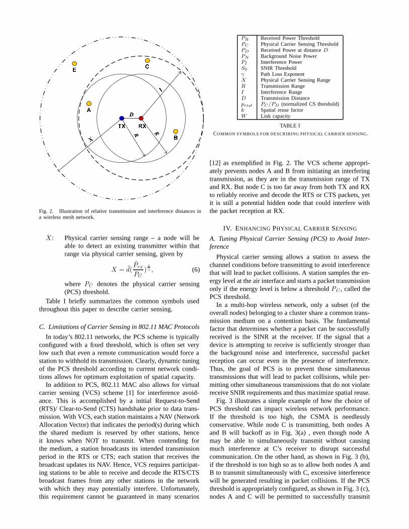
Fig.2 shows a typical mesh network with a referencetransmission from a node TX to a node RX in the presenceof four other nodes (A, B, C, and E). The same transmissionpower is used by every node in the network. We define thefollowing:
D: TX-RX separation distance, defines PD =Prx(D).
R: Transmission range, given by
R = d(Prx
max(PR, S0PN ))
1γ = d(
Prx
PR)
1γ , (3)
I: Interference range – implies a single transmitterwithin that range of the receiver will disruptreception of the desired transmitter, given by
I = D(1
1S0
− (Dd)γ PN
Prx
)1/γ . (4)
With negligible background noise, Eq.4 turns to
I ≈ S1/γ0 D. (5)
Fig. 2. Illustration of relative transmission and interference distances ina wireless mesh network.
X : Physical carrier sensing range – a node will beable to detect an existing transmitter within thatrange via physical carrier sensing, given by
X = d(Prx
PC)
1γ , (6)
where PC denotes the physical carrier sensing(PCS) threshold.
Table I briefly summarizes the common symbols usedthroughout this paper to describe carrier sensing.
C. Limitations of Carrier Sensing in 802.11 MAC Protocols
In today’s 802.11 networks, the PCS scheme is typicallyconfigured with a fixed threshold, which is often set verylow such that even a remote communication would force astation to withhold its transmission. Clearly, dynamic tuningof the PCS threshold according to current network condi-tions allows for optimum exploitation of spatial capacity.
In addition to PCS, 802.11 MAC also allows for virtualcarrier sensing (VCS) scheme [1] for interference avoid-ance. This is accomplished by a initial Request-to-Send(RTS)/ Clear-to-Send (CTS) handshake prior to data trans-mission. With VCS, each station maintains a NAV (NetworkAllocation Vector) that indicates the period(s) during whichthe shared medium is reserved by other stations, henceit knows when NOT to transmit. When contending forthe medium, a station broadcasts its intended transmissionperiod in the RTS or CTS; each station that receives thebroadcast updates its NAV. Hence, VCS requires participat-ing stations to be able to receive and decode the RTS/CTSbroadcast frames from any other stations in the networkwith which they may potentially interfere. Unfortunately,this requirement cannot be guaranteed in many scenarios
PR Received Power ThresholdPC Physical Carrier Sensing ThresholdPD Received Power at distance DPN Background Noise PowerPI Interference PowerS0 SNIR Thresholdγ Path Loss ExponentX Physical Carrier Sensing RangeR Transmission RangeI Interference RangeD Transmission Distancepcs t PC/PD (normalized CS threshold)k Spatial reuse factorW Link capacity
TABLE I
COMMON SYMBOLS FOR DESCRIBING PHYSICAL CARRIER SENSING.
[12] as exemplified in Fig. 2. The VCS scheme appropri-ately prevents nodes A and B from initiating an interferingtransmission, as they are in the transmission range of TXand RX. But node C is too far away from both TX and RXto reliably receive and decode the RTS or CTS packets, yetit is still a potential hidden node that could interfere withthe packet reception at RX.
IV. ENHANCING PHYSICAL CARRIER SENSING
A. Tuning Physical Carrier Sensing (PCS) to Avoid Inter-ference
Physical carrier sensing allows a station to assess thechannel conditions before transmitting to avoid interferencethat will lead to packet collisions. A station samples the en-ergy level at the air interface and starts a packet transmissiononly if the energy level is below a threshold PC , called thePCS threshold.
In a multi-hop wireless network, only a subset (of theoverall nodes) belonging to a cluster share a common trans-mission medium on a contention basis. The fundamentalfactor that determines whether a packet can be successfullyreceived is the SINR at the receiver. If the signal that adevice is attempting to receive is sufficiently stronger thanthe background noise and interference, successful packetreception can occur even in the presence of interference.Thus, the goal of PCS is to prevent those simultaneoustransmissions that will lead to packet collisions, while per-mitting other simultaneous transmissions that do not violatereceive SNIR requirements and thus maximize spatial reuse.
Fig. 3 illustrates a simple example of how the choice ofPCS threshold can impact wireless network performance.If the threshold is too high, the CSMA is needlesslyconservative. While node C is transmitting, both nodes Aand B will backoff as in Fig. 3(a) , even though node Amay be able to simultaneously transmit without causingmuch interference at C’s receiver to disrupt successfulcommunication. On the other hand, as shown in Fig. 3 (b),if the threshold is too high so as to allow both nodes A andB to transmit simultaneously with C, excessive interferencewill be generated resulting in packet collisions. If the PCSthreshold is appropriately configured, as shown in Fig. 3 (c),nodes A and C will be permitted to successfully transmit
Fig. 3. Physical Carrier Sensing (PCS) and Spatial Reuse.
simultaneously while node B will be forced to back offto prevent packet collisions. When the PCS threshold isoptimized, maximal spatial reuse can be achieved withoutpermitting packet collisions.
When properly tuned, PCS is more robust than VCS,because it does not require control packets to be receivedand correctly decoded. It is also more flexible, since thePCS sensing range can be easily adjusted by tuning thePCS threshold. In Fig.2, all potentially interfering nodes,including node C, can be eliminated by enlarging the PCSsensing range to cover the entire potential interference area,i.e.
X ≥ D + I. (7)
Combining Eq.7 with Eq.5, we obtain
X ≥ D(1 + S1/γ0 ), (8)
that leads to
pcs t ≤ 1
(1 + S1/γ0 )γ
. (9)
A potential downside of this approach is the exposedterminal problem [10]. For example, in Fig. 2 even thougha transmission by node E will not disrupt RX, E will deferits transmission because it lies within the sensing range.Having too many exposed terminals can potentially reducethe overall network throughput. However, by tuning thephysical carrier sensing threshold, we will demonstrate agood tradeoff between solving the hidden terminal problemand exacerbating the exposed terminal problem, therebyobtaining high aggregate throughput.
B. Estimating Optimal PCS Threshold to Maximize SpatialReuse
As already motivated by the earlier example, choosing theoptimal PCS threshold can maximize spatial reuse leadingto increased aggregate network one-hop throughput. Inorder to establish some preliminary guidelines for the choiceof an optimal PCS threshold, we assume a homogeneousnetwork with identical interference environment at eachnode 3. The optimal spatial reuse is achieved when thenumber of simultaneous successful transmissions reachesthe maximum. For successful reception at a receive node,the net interference and noise cannot exceed the tolerablelevel according to Eq.2,
PI + PN ≤ PD/S0, (10)
With the assumption that the transmitter and the receiverperceives the same interference and noise level, the optimalPCS threshold should satisfy
PC ≤ PD/S0, (11)
for successful simultaneous transmissions. Hence, PD/S0
is the optimal PCS threshold for maximum spatial reuse;a higher PD/S0 implies more simultaneous transmissionsand greater reuse. The corresponding optimal p cs t denotedas β, is then
β =1S0
(12)
independent of path loss exponent γ.Recall Eq.9 that provides a necessary condition for com-
pletely eliminating the interference from hidden nodes. Theratio ρ of the exposed terminal area to the whole PCSsensing area is given by
ρ =πX2 − πI2
πX2≈
D2(1 + S1/γ0
)2 − D2S2/γ0
D2(1 + S1/γ0
)2= 1 − (
S1/γ0
1 + S1/γ0
)2. (13)
When S1/γ0 is small, ρ is not negligible; but for S
1/γ0 >> 1
4, we have ρ ≈ 0 so that the exposed terminal problem canbe ignored, and Eq.9 reduces to pcs t ≤ β.
C. Analysis Model for Aggregate Throughput Limits
In [7], spatial reuse for a homogeneous ad-hoc environ-ment was investigated where every transmitter uses the sametransmission power and data rate, and communicates to animmediate neighbor at the constant T-R distance d. Thespatial reuse can be characterized by the distance betweenneighboring simultaneous transmitters (T-T separation). Theoptimal spatial reuse (min. T-T separation) for two regularnetwork topologies: the 1-D chain network and the 2-D gridnetwork were derived. Let k denote the T-T distance (also
3Clearly, this assumption is a main drawback of the subsequent analysis,but further refinements are not possible without assuming specific networktopologies. The results here thus have the advantage of not being tied toa specific topology.
4More so for higher data rates since higher S0 values will be required.
called spatial reuse factor) measured in number of hops (hopdistance d equals inter-node separation), then k must satisfy
k ≥
[2
(1 + 1
γ−1
)S0
] 1γ
, Chain network
k ≥[6
(1 + 1
γ−2
)S0
] 1γ
, 2-D grid(14)
We assume that a suitable MAC protocol schedulessimultaneous communication only for transmitters that are khops away; the network then reaches its aggregate through-put limit. In a chain network of N nodes, a packet must berelayed by each of the N − 2 intermediate nodes in orderto be routed from one end to the other. Since at most N/ksimultaneous transmitters can be supported in the chain, theend-to-end throughput Ce2e is approximated by
Ce2e ≈ W
N× N
k=
W
k(15)
where W denotes the link capacity.
V. A MULTI-CHANNEL TWO-RADIO ARCHITECTURE
WITH CLUSTERING
A multi-channel architecture with clustering was previ-ously studied in [23], which only considered a centralizedTDMA MAC and one radio. Here, we propose to integratetwo 802.11 radios (default and secondary) per node: thedefault radio is used for inter-cluster communications; whilethe secondary radio is for intra-cluster communications.Unlike most existing multi-channel approaches, the newclustered multi-channel two-radio (CMT) architecture notonly eliminates the need for switching channels on a packet-by-packet basis, but is also fully compatible with legacydevices. Fig.4 shows an example of a mesh network usingthe CMT architecture with three orthogonal channels, whereeach circle represents an independent cluster.
Fig. 4. Clustering Multiple Channels Architecture with Two Radios
Fig. 5 shows protocol stack in a two-radio device. Wehighlight the two new modules - MAC Extension andSecondary MAC/PHY - needed to enable the two-radiofunctionality. Algorithms in the new architecture are imple-mented in the MAC Extension. The secondary MAC/PHYhas no administrative functionality, such as association,authentication etc. and can transmit only data traffic.
Fig. 5. Two-Radio Protocol Stacks
Clustering is accomplished by using the Highest-Connectivity Cluster (HCC) algorithm first proposed in[22], based on the following rules:
• A node is elected as a clusterhead if it is the mosthighly connected (having the highest number of neigh-boring nodes) node of all its “uncovered” neighbornodes (in case of a tie, lowest ID (e.g. MAC address)prevails);
• A node which has not elected its clusterhead is an“uncovered” node, otherwise it is a ”covered” node;
• A node which has already elected another node as itsclusterhead gives up its role as a clusterhead.
To minimize the co-channel interference (CCI) amongclusters, we propose a Minimum Interference Channel Se-lection (MIX) algorithm, by which a clusterhead selects thesecondary radio channel (denoted as k) with the minimumenergy on air for intra-cluster communication.
Let Ei denote the average energy on the ith channel forthe duration T , we have
Ei =
∫ t0+T
t=t0Ei(t)dt
T, (16)
where Ei(t) is the instantaneous energy on the ith channelat time t. Hence, the MIX algorithm is represented by
{k | Ek = min(Ei|i = {1, 2, ..., n})}, (17)
where n is the total number of orthogonal channels. Obvi-ously, the longer the estimation duration T , the more accu-rate the estimation. Our simulations used T = 2 seconds.
A clusterhead will generate a pseudo random numberwith 6 bits length for the ID of its cluster. Also it isresponsible for notifying all its members which channel isused to configure the secondary radio as well as when thechannel information is expired (denoted as TE (Eq.18)).
TE = To + T1 + uniform(0, T2), (18)
where To indicates the time when the clusterhead selectedthe channel, and T1 and uniform(0, T2) 5 give the constantand random components of the lifetime, respectively. Oursimulations used T1 = T2 = 100 seconds.
When the channel information is expired, the clusterheadwill re-run the MIX algorithm to select a new channel, then
5a random variable with uniform distribution on the range (0, T2); therandom component is designed to avoid the event that two clusters alwaysselect the channel at the same time, i.e., channel selection collisions.
broadcast the updated channel and its lifetime to its clustermembers.
After getting the channel information, the neighboringnodes notify each other the channel used by their secondaryradio. Thereby, we build a new 16-bit CMT field (see Fig.6)with three sub-fields: status, channel, and number of un-covered neighboring nodes. The “cluster-ID” flag indicatesthe cluster that the node belongs to, and is only meaningfulwhen “status” is not “uncovered”; the “number of uncoveredneighboring nodes” is used for electing clusterhead. In ourOPNET implementation, the new 16-bit CMT field is addedinto the 802.11 DATA frame. The 16-bit “Duration ID” fieldin the legacy 802.11 ACK frame can also be used as thenew CMT field, since it is meaningless when segmentationis not used or the ACK is for the last fragment of the packet.
Fig. 6. Definition of 16-Bit CMT Field
After learning that a peer node belongs to the samecluster, a node will configure the forwarding table in itsextended MAC such that all packets destined to the peernode go through the secondary MAC/PHY module. Fig.7summarizes the above clustering and channel selectingprocedures with a state transition diagram.
Fig. 7. A State Transition Diagram of Clustering and Channel SelectingProcedures
VI. SIMULATION RESULTS AND DISCUSSIONS
In this section, we present results from a series ofsimulations to demonstrate the effectiveness of physicalcarrier sensing with tunable sensing thresholds in improving
network performance for various topologies. All the simula-tions were conducted in the OPNET simulation environment[15]. We have extended OPNET kernel modules to supporttunable physical carrier sensing, a configurable propagationenvironment and multiple 802.11b data rates.
In all simulations, we configured each node to be alwaysbacklogged with 1024 bytes long MAC data frames. Eachnode transmits at a fixed power of 0 dbm. By default, theOPNET simulator configures the physical carrier sensingthreshold to be the same as the reception threshold PR.Furthermore, the ambient noise level was set at −200 dBm.
The primary performance metric studied in this paper isthroughput, defined as the total number of bits successfullyreceived in a second. As per the .11 MAC, if the senderdoes not receive an ACK for a transmitted data packet,it assumes that the data packet is lost and performs aretransmission. However, it is also possible that the datapacket is received correctly, but the ACK is lost. This alsocauses a retransmission and can result in a multiple copiesof the same data packet at the receiver. In this case, onlythe first one received will be forwarded up to higher layers,and the rest discarded. When computing throughput in thispaper, we only count successful non-duplicate data packets ,i.e. the goodput which underestimates the actual throughputon the physical channel of the network. However, sinceACK packets are much shorter than data packets and theyare typically transmitted using the lowest (most reliable)data rate in 802.11, the probability of successfully receivinga data packet but losing an ACK packet is very low.Thus, we assume that throughput is approximately equalto goodput in an 802.11 network.
Note that the .11 MAC employs contention manage-ment via the binary exponential backoff (BEB) with aconfigurable contention window (CW) size parameter. Thisrandom scheduling of user transmissions naturally impactsthe received SINR in addition to the various mechanismsdescribed in this paper. Since the primary focus of thesimulations in this section is on interference avoidance viaPCS, the BEB mechanism is disabled in our simulationsand the contention window size is fixed at the maximumvalue for 802.11b (CW = 1024) to minimize the likelihoodof collisions due to simultaneous transmission. This config-uration allows us to isolate the specific effects of adaptivephysical carrier sensing on network performance.
A. Point-to-point baseline performance of 802.11b MAC
To validate the effectiveness of physical carrier sensing,we need the following two baseline figures: the SINRthresholds (S0) required to sustain each available data ratein an 802.11b network, and the effective MAC throughputat each data rate. In the first simulation, we configureda network of two nodes – one sender and one receiver.The pathloss exponent was set to 2 to reflect a free-spaceenvironment. With RTS/CTS disabled, we varied the T-Rseparation distance and measured the effective throughputprovided by the MAC layer at the receiver. The samesimulation sequence was repeated for all four data ratesdefined in the 802.11b standard.
4 6 8 10 12 14 16 18 20 22 24
0
1x10⁶
2x10⁶
3x10⁶
4x10⁶
5x10⁶ 11 Mbps 5.5 Mbps 2 Mbps 1 Mbps
One
-Hop
MA
C C
apac
ity (
bps)
SNIR (db)
Fig. 8. One-Hop multi-rate performance of 802.11b for various SINRvalues at the receiver (RTS/CTS disabled).
Data Rate (Mbps) 1 2 5.5 11S0 (dB) 11 14 18 21
W (Mbps) 0.89 1.5 3.5 5.0
TABLE II
ONE-HOP PERFORMANCE OF 802.11B MAC WITHOUT RTS/CTS
The results are shown in Fig.8 where instead of the T-Rdistance, the throughput is shown against the SINR at re-ceiver. Hence the results depict the fundamental relationshipbetween MAC throughput and receiver SINR. This mappingis valid irrespective of pathloss, transmission power and T-R distance. These results, recorded in Table II, will be usedto design and analyze simulations in the rest of the section.The results confirm that MAC overhead is generally largerat higher data rates and higher data rates require higherSINR thresholds, as expected.
B. Maximizing Spatial Reuse with the Optimal PCS
We conduct simulations in two scenarios with regulartopology: 90-node chain and 10 × 10 grid. The goal is tovalidate the theoretical optimal PCS threshold β, derived inSection IV-B.
First, we expanded the previous network into a chainof 90 nodes (to approximate an infinite chain). The onlytraffic allowed is originated by node 1 and designated fornode 90, with the other 88 intermediate nodes acting asrelays. The reception power threshold (PR) was configuredsuch that the transmission range is 13 meters. Each noderelied on physical carrier sensing only to avoid interferenceusing identical carrier sensing threshold and data rates.We measured the end-to-end throughput while varying thesensing threshold and the data rate. The results for γ = 2are plotted in Fig. 9.
Note that the results show the existence of an optimalsensing threshold value for each data rate. With everythingelse fixed, altering the data rate changes the SINR require-ment (S0), hence the optimal sensing threshold changesas well. Also notice that the common practice of havingthe carrier sense threshold equal to the reception threshold,
i.e., Pcs t = 0db corresponds to the right-most pointon respective curves. Hence, the throughput improvementachieved by tunable physical carrier sensing threshold canbe as high as 4 times (at data rate 11 Mbps).
-30 -25 -20 -15 -10 -5 0
30k40k50k60k70k80k90k
100k110k120k130k140k150k160k170k180k190k200k
γ=2, n=90, Ptx=0dbm, PN = - 200dbm, d = 12.5 m, R =13 m
1 Mbps 2 Mbps 5.5 Mbps 11 Mbps
E2E
Thr
ough
put (
bps)
pcs_t (dB)
Fig. 9. End-to-end throughput in a 90-hop chain for various sensingthresholds and data rates.
Table III compares the optimal sensing threshold pcs t
obtained from the simulations against the theoretical opti-mum β. As the table shows, the two values matches verywell.
OPTIMAL CARRIER SENSING THRESHOLDS (DB) IN A 90-NODE CHAIN
Table IV compares the optimal throughputs obtained fromthe simulations against the prediction from the spatial reusestudy described in Sec.III-C. The theoretical predictionassumed a perfect MAC protocol that always derives theglobally optimal schedule for communications; this yields atheoretical upper-bound of network throughput. As shown inTable IV, the network with optimally tuned physical carriersensing was able to achieve around 90% of the theoreticalmaximum.
Next, we turn to a 2-D network: 10 × 10 grid, which ismore representative of typical real world topologies. Eachpacket has its own destination chosen randomly from theimmediate neighbors of the transmitter. In this configura-tion, the Manhattan distance between neighboring nodes
was 4.5 meters. The reception power threshold (PR) wasconfigured to allow the transmission range of only 4.5meters such that only immediate neighbors could directlycommunicate.
We conducted four sets of simulations using 1 Mbps,2 Mbps, 5.5 Mbps and 11 Mbps as the data rate for eachnode, respectively. In each set of the simulations, we alteredthe path loss exponent and PCS threshold. The aggregatethroughput of the grid network are plotted in Fig. 10. It isevident that the optimal PCS threshold does not change withthe path loss exponent in a large homogeneous network, andthe optimal PCS threshold obtained via simulation matchesthe theoretical β very well (see Table V).
SIMULATION RESULTS OF OPTIMAL CARRIER SENSING THRESHOLDS
(DB) IN A 10 × 10 802.11B GRID
The simulation is now repeated for 802.11a 6. Table VIcompares the theoretical optimal pcs t (i.e. β) with theoptimal value from simulations, showing that the theoreticaloptimal carrier sensing threshold β is also valid for 802.11anetwork.
C. Optimal PCS + Multi-Channel Clustering
Fig. 11 shows an example of how our clustering multi-channel and two-radio architecture works in a 10 × 10
6We use the same modulation curve for 802.11a simulation as in [18]
OPTIMAL CARRIER SENSING THRESHOLDS (DB) IN A 10 × 10 802.11A
GRID WITH DIFFERENT DATA RATE (MBPS) (γ = 3)
Fig. 11. An Example of 10×10 Grid Using the Clustering Multi-Channeland Two-Radio Architecture
regular grid with three orthogonal channels. We implementa two-radio 802.11 client module in OPNET. Let d denotethe distance between two nearest neighbors; we configurethe transmission range as
√2d. During the simulation,
the network will automatically cluster into the topologyas shown in Fig.11. The dark nodes are clusterhead, andthe dotted circle indicates all independent clusters. Twoorthogonal channels (for the circles denoted by thick andthin dash lines, respectively) are used for intra-cluster com-munications. The channel assignment in Fig.11 minimizesco-channel interference and achieves the highest spatialreuse.
Fig.12 compares the total one-hop throughput with thenew clustering multi-channel and two-radio architecture tothe traditional single-channel, single-radio mesh. A randomtraffic generation model at each node was used with asufficiently high offered load such that the nodes remainsaturated during the simulation. Fig.12 clearly demonstratesthe performance improvement with clustering and multipleorthogonal channels. The steady-state average throughput is8.1 Mbps in the new CMT architecture, and only 2.7 Mbpsin the single-channel and single-radio mesh. The gain isabout 300%, which is the maximum gain achievable whenusing 3 orthogonal channels.
Fig.13 illustrates the one-hop throughput distribution withrespect to links, where links Ai, Bi, and Ci are alsoindicated in Fig. 11 (i = {1, 2, ..., 10}). Clearly, links Ai ex-perience worse interference environment than links B i and
0 100 200 300 400 5000
1M
2M
3M
4M
5M
6M
7M
8M
9M
Data Rate = 1MbpsPacket Size = 1024 BytesPath Loss Exponent = 3
Traditional Single-Channel and Single-Radio Mesh
Clustering Multi-Channel and Two-Radio Architecture
Thr
ough
put (
bps)
Time (sec.)
Fig. 12. Total One-Hop Throughput Comparison
0 100 200 300 400 500 600 700
100
1000
10000
100000 C10C9C8
C7
C6C5C4
C3C2C1 B10B9
B8
B7B6B5
B4B3B2B1
A10
A9
A8
A7
A6A5A4A3
A2
A1
One
-Hop
Thr
ough
put (
bps)
Link
Clustering Multi-Channel and Two-Radio Mesh Traditional Single-Channel and Single-Radio Mesh
Fig. 13. Average One-Hop Throughput Distribution (between 300sec.and 500 sec.)
Ci, leading to the oscillation of the throughput distribution,illustrating the location-dependent fairness problem. We donot consider the fairness problem further; it is interestingto speculate how physical carrier sensing may be used tomitigate the location-dependent fairness problem. It impliesfor instance that the preferable locations for gateways in awireless mesh network may not be the center of the network.
Finally, we validate the new architecture in a randomtopology as shown in Fig.14. The transmission range isfixed at 25 meters. We color-coded the graph in Fig.14. Redand blue indicates the nodes using channel 1 and channel2 for their secondary radio, respectively; while black nodesare the single-node clusters. We also used the circles toillustrate the clusters with clusterhead in the center. Fig.15compares the performance with both aggregate throughputand throughput distribution. We clearly see that (after 300seconds) the aggregate throughput of the proposed archi-tecture (10Mbps) is almost 3 times higher than that of thetraditional one (3.5Mbps).
Fig. 14. 2D 200m x 200m 100-Nodes Random Topology Using theClustering Multi-Channel and Two-Radio Architecture (at 500 seconds)
0 100 200 300 400 5000
1M
2M
3M
4M
5M
6M
7M
8M
9M
10M
Data Rate = 1MbpsPacket Size = 1024 BytesPath Loss Exponent = 3
Traditional Single-Channel and Single-Radio Mesh
Clustering Multi-Channel and Two-Radio Architecture
Thr
ough
put (
bps)
Time (sec.)
100 200 300 400
100
1000
10000
100000
One
-Hop
Thr
ough
put (
bps)
Link
Clustering Multi-Channel and Two-Radio Mesh Traditional Single-Channel and Single-Radio Mesh
a) Tracing Aggregate Throughput b) Throughput Distribution
Fig. 15. Performance Comparison in the Random Topology
VII. CONCLUSION
In this paper, we propose to enhance physical carriersensing with a dynamically tunable sensing threshold andadopt a novel clustering two-radio and multi-channel archi-tecture to improve spatial reuse in 802.11 mesh networks,aiming at increasing the aggregate network throughput.Simulations were performed for both 1-D chain and 2-Dgrid topologies to validate the analysis and the proposedscheme. The main contributions of this paper are:
(1) We have demonstrated that physical carrier sens-ing with the tunable sensing threshold is effectiveat leveraging spatial reuse in 802.11 multi-hopmesh networks, shown by increases in aggregatethroughput. This improvement is achieved with-out requiring the use of virtual carrier sensing.Although the 802.11 MAC is a CSMA/CA baseddistributed and asynchronous scheme, it has thecapability to make good use of the spatial-reuseproperty in a mesh (90% of the theoretical limitin a chain).
(2) We have proposed an adaptive PCS scheme toachieve a near-optimal carrier sense threshold au-
tomatically, leading to a substantial throughputimprovement for 802.11 mesh networks. With as-sumptions of homogeneous links and co-locationof sender and receiver, 1/S0 gives the theoreticalapproximation to the optimal sensing threshold,where S0 is the SINR threshold for achieving thelink capacity.
(3) We have presented a new clustering multi-channeland two-radio (CMT) architecture using 802.11MAC protocols. Distributed clustering works witha new minimum interference channel selectionalgorithm (MIX) to distribute orthogonal channelsin a mesh, maximizing the aggregate throughput.OPNET simulations were conducted to validatethe new architecture. Compared to a traditionalsingle-channel and single-radio mesh, the gainachieved with three orthogonal channels in termsof the aggregate one-hop throughput is about300% in a 10×10 grid using local, random, andsaturate traffic as well as in a 200m x 200m 100-nodes random topology.
Although this paper is focused on 802.11 networks, theanalysis on optimal physical carrier sensing is applicableto any CSMA/CA-based mesh network. As the initial stepto showcase the potential of enhanced physical carriersensing and multi-channel clustering in improving aggregatethroughput, this paper focuses on regular network topolo-gies. Future work may include extending the investigationto random topologies.
ACKNOWLEDGEMENT
The work of Jing Zhu and Sumit Roy was supported inpart by an Intel Research Council Grant.
REFERENCES
[1] IEEE Standard for Wireless LAN Medium Access Control (MAC)and Physical Layer (PHY) specifications, ISO/IEC 8802-11: 1999(E),Aug. 1999.
[2] MeshDynamics, http://www.meshdynamics.com.[3] MeshNetworks, http://www.meshnetworks.com.[4] Packethop, http://www.packethop.com[5] B. P. Crow, J. G. Kim, IEEE 802.11 Wireless Local Area Networks,
IEEE Comm. Mag., Sept. 1999.[6] G. Bianchi, Performance Analysis of the IEEE 802.11 Distributed
Coordination Function, IEEE JSAC, vol. 18, no. 3, March 2000.[7] X. Guo, S. Roy, W. Steven Conner, Spatial Reuse in Wireless Ad-Hoc
Networks, VTC2003.[8] X. Guo, ”Personal research notes”, 2003.[9] A. Adya, P. Bahl, J. Padhye, A. Wolman and L. Zhou, ‘A Multi-radio
Unification Protocol for IEEE 802.11 Wireless Networks,” Tech. Rpt.MSR-TR-2003-44, July 2003.
[10] D. Shukla, L. Chandran-Wadia, S. Iyer, Mitigating the exposed nodeproblem in IEEE 802.11 adhoc networks, IEEE ICCCN 2003, Dallas,Oct 2003.
[11] F. A. Tobagi, L. Kleinrock, Packet Switching in Radio Channels:PART II- The Hidden Terminal Problem in Carrier Sensing MultipleAccess and Busy Tone Solution”, IEEE Trans. on Commun, Vol.COM-23, No. 12, pp. 1417-1433, 1975.
[12] K. Xu, M. Gerla, S. Bae, How effective is the IEEE 802.11 RTS/CTShandshake in ad hoc networks?, GLOBECOM02, Nov 17-21, 2002.
[13] S. Xu, T. Saadawi, Does the IEEE 802.11 MAC Protocol WorkWell in Multihop Wireless Ad Hoc Networks? IEEE CommunicationsMagazine, P130-137, June 2001.
[14] F. Ye, B. Sikdar, Improving Spatial Reuse of IEEE 802.11 Based AdHoc Networks, To appear in the Proceedings of IEEE GLOBECOM,San Francisco, December 2003.
[15] http://www.opnet.com[16] Intersil, Direct Sequence Spread Spectrum Baseband Processor, Doc#
FN 4816.2, Feb. 2002, http://www.intersil.com/[17] V.Bharghavan, A. Demers, S. Shenker, and L. Zhang, MACAW:
A Media Access Protocol for Wireless LANs, in Proc. Of ACMSIGCOMM’94,
[18] A.J. van der Vegt, Auto rate fallback algorithm for the ieee 802.11astandard, http://www.phys.uu.nl/ vdvegt/docs/gron/.
[19] Theodore S. Rappaport. Wireless Communications, Principles andPractices, 2nd Ed. Prentice Hall, 2002. ISBN 0-13-042232-0
[20] J. Monks, V. Bharghavan, W. Hwu, A Power Controlled MultipleAccess Protocol for Wireless Packet Networks, in IEEE INFOCOM,April 2001.
[21] R. Roy Cloudhury, X. Yang, R. Ramanathan and N. H. Vaidya,Using Directional Antenna for Medium Access Control in Ad HocNetworks, in ACM MOBICOM, Atlanta, GA, Sept. 2002.
[22] M. Gerla and J.T.-C. Tsai, ”Multicluster, mobile, multimedia radionetwork”, ACM/Baltzer Journal of Wireless Networks. vol. 1, (no.3), 1995, p. 255-265.
[23] C. R. Lin, M. Gerla, ”Adaptive Clustering for Mobile WirelessNetworks,” IEEE Jour. Selected Areas in Communications, pp. 1265-1275, Sept. 1997.
[24] Y. P. Chen and A. L. Liestman, ”A Zonal Algorithm for Clustering AdHoc Networks”, International Journal of Foundations of ComputerScience, 2003.
[25] N. Jain and S. Das, A Mutlichannel CSMA MAC Protocol withReceiver-Based Channel Selection for Mutlihop Wireless Networks,in Proceedings of the 9th Int. Conf. on Computer Communicationsand Networks (IC3N), Oct. 2001.
[26] S.-L. Wu, C.-Y. Lin, Y.-C. Tseng and J.-P. Sheu, A New Mutli-Channel MAC Protocol with On-Demand Channel Assignment forMulti-Hop Mobile Ad Hoc Networks, in IEEE Wireless Commu-nications and Networking Conference (WCNC), Chicago, IL, Sept.2000.
[27] A. Adya, P. Bahl, J. Padhye, A. Wolman, and L. Zhu, A Multi-RadioUnification Protocol for IEEE 802.11 Wireless Networks, MicrosoftResearch, Technical Report MSR-TR-2003-44, July, 2003.