May 2014, Volume 16, No. 5 continued on page 2 The desired result of tightening a fastener is to obtain a proper clamping force between the parts. The clamping force prevents loosen- ing when the vehicle is in use and external forces act on the clamped parts. All fasteners have a specified torque. The method used for a particular application is determined by Engineering and specified in the Ser- vice Information. It is necessary to apply the fastener torque to the specific fastener identified. Applying torque to the mating fastener can damage the fastener, mating components, or provide insufficient clamp load. For example, when installing the adjust link on the 2014 Corvette rear suspension, the Service Information calls for tightening the adjust link nut to 70 N•m (52 lb. ft.), not the cam bolt. There are three different methods for the specification of tightening fasteners: Torque (T), Torque Plus Angle (TA), and Torque Plus Angle to Yield (TAY). Torque Plus Angle to Yield (TAY) is sometimes referred to Torque To Yield (TTY). A fastener specification of Torque Plus Angle (TA) — for example, 30 N•m (22 lb. ft.) + 120 degrees — has more clamping force than a fastener specification of Torque (T) — for ex- ample, 30 N•m (22 lb. ft). A fastener specification of Torque Plus Angle to Yield (TAY) has The Multiple Diagnostic Interface (MDI) tool features a temporary backup power source (four AAA batteries) for use during a crank event or in the event the DLC cable is accidently disconnected during a programming event. Due to the limited use of this power source, the batteries tend to reside in the MDI unit for extended lengths of time. This can increase the chances of the batteries leaking and causing damage to the unit. It’s recommended that the batteries be checked periodically for leakage. The batteries should be replaced often to prevent this scenario. MDI backup batteries 80 N . m (59 lb ft) plus 130° Understanding Fastener Tightening Specifications TECH LINE news CONTENTS Understanding Fastener Tightening Specifications ....................... 1 MDI Backup Batteries ................. 1 Shifter Handle Returns ................ 2 Using the J-45059 Angle Meter ......... 3 Roof Beacon Lighting Harness .......... 3 Heated Seat May Turn Off ............. 4 Backup Camera Inoperative ............ 4 A/C Tube Repair Kits ................. 4 New 15-Digit Battery Warranty Code ..... 5 CTS Hazard Flashers Switch ............ 5 Lamp Damage and Lamp Condensation . . . 6 Brake Noise during Slow Stops .......... 7 Rechargeable Energy Storage System Smoke Testing ................ 8 Corvette Driver Mode Control .......... 9 Service Know-How ................... 9 Car Issues – Fix It Right the First Time . . . 10 Truck Issues – Fix It Right the First Time . . 10 Customer Care and Aftersales MDI Backup Batteries continued on page 3
Transcript
May 2014, Volume 16, No. 5
continued on page 2
The desired result of tightening a fastener is to obtain a proper clamping force between the parts. The clamping force prevents loosen-ing when the vehicle is in use and external forces act on the clamped parts.
All fasteners have a specified torque. The method used for a particular application is determined by Engineering and specified in the Ser-vice Information. It is necessary to apply the fastener torque to the specific fastener identified. Applying torque to the mating fastener can damage the fastener, mating components, or provide insufficient clamp load. For example, when installing the adjust link on the 2014 Corvette rear suspension, the Service Information calls for tightening the adjust link nut to 70 N•m (52 lb. ft.), not the cam bolt.
There are three different methods for the specification of tightening fasteners: Torque (T), Torque Plus Angle (TA), and Torque Plus Angle to Yield (TAY). Torque Plus Angle to Yield (TAY) is sometimes referred to Torque To Yield (TTY).
A fastener specification of Torque Plus Angle (TA) — for example, 30 N•m (22 lb. ft.) + 120 degrees — has more clamping force than a fastener specification of Torque (T) — for ex-ample, 30 N•m (22 lb. ft). A fastener specification of Torque Plus Angle to Yield (TAY) has
The Multiple Diagnostic Interface (MDI) tool features a temporary backup power source (four AAA batteries) for use during a crank event or in the event the DLC cable is accidently disconnected during a programming event.
Due to the limited use of this power source, the batteries tend to reside in the MDI unit for extended lengths of time. This can increase the chances of the batteries leaking and causing damage to the unit. It’s recommended that the batteries be checked periodically for leakage. The batteries should be replaced often to prevent this scenario.
Some shifter handles on some 2014 CTS Sedans have been re-placed for a Service Transmission Soon message on the Driver Information Center (DIC) and an inoperative Manual Mode (M) button on the shift knob. DTC P0827 (Up and Down Shift Switch Circuit Low Voltage) may be stored.
Some shifter handles returned to the Warranty Parts Center (WPC) have had the wires separated from the small white con-nector and the connector was not returned with the shifter knob.
The connector has a wire crimp inside it that is crucial to analyzing the root cause of this condition.
If the white connector is separated from the wires on the shifter knob, locate it and ensure it is returned with the shifter handle to the WPC.
Thanks to Jean Hart
more clamping force than a fastener speci-fication of Torque Plus Angle (TA).
Torque (T)
A fastener with a Torque (T) specifica-tion can be tightened with a con-ventional torque wrench.
TIP: Generally, externally threaded fasteners (bolts, screws, studs) tightened to this specification method can be re-used, unless otherwise specified in the Service Information.
Torque Plus Angle (TA)
A fastener with a Torque Plus Angle (TA) specification must be tightened first to the torque part of the specification and then must be tightened further by the addition of the specified angle. The angle must be applied relative to the mating fastener, if present, or relative to the mating sur-face. A backup wrench must be used, if required, to prevent the rotation of the mating fastener while the angle is added to the fastener with the Torque Plus Angle (TA) specification.
TIP: Generally, externally threaded fasteners tightened to this specification method can be reused, unless otherwise specified in the Service Information.
Torque Plus Angle to Yield (TAY)
A fastener with a Torque Plus Angle to Yield specification (TAY) is tightened in the same way as the fastener with the
Torque Plus Angle (TA) specification.
The difference between a Torque Plus Angle (TA) specification and a Torque Plus Angle to Yield (TAY) specification is the tightening results in permanent deforma-tion of the externally threaded fastener.
TIP: Externally threaded fasteners tightened to this specification method must not be reused and must always be replaced if loosened.
Tightening in Stages
Generally, Service Information specifies a fastener tightening specification in stages. An individual fastener with a Torque (T) specification is tightened to the specified torque in one pass.
For Torque Plus Angle (TA) and Torque Plus Angle to Yield (TAY) specification fasteners, the fasteners are tightened in stages. All the fasteners are tightened to a torque specification on the first pass. Next, they receive another tightening to a specified angle (in degrees) on the second pass. Sometimes, more than two passes are required. Always refer to the appropri-ate Service Information for proper tighten-ing in stages.
On applications with more than one fas-tener, such as wheel nuts or cylinder head bolts, the fasteners should be tightened to specification by alternating between the fasteners to ensure the parts are not distorted and that the fasteners are torqued evenly. Once a specified minimum of torque has been achieved for each bolt, the bolts should be tightened completely to specification.
Reusing the Fastener
Think of an externally threaded fastener (bolt, screw or stud) as a spring. As a Torque (T) or Torque Plus Angle (TA) tightening specification is applied, the spring (externally threaded fastener) is stretched. With a Torque (T) or Torque Plus Angle (TA) tightening specification,
the spring returns to its original length (elastically stretched) when loosened. In the case of a Torque Plus Angle to Yield (TAY) tightening specification, the spring is overstretched (plastically deformed) and does not return to its original length. For this reason, the Torque Plus Angle to Yield (TAY) tightening specification requires the externally threaded fastener to always be replaced.
In the Service Information, the following warning will be shown when a Torque Plus Angle to Yield (TAY) specification fastener is used:
TIP: There is no effect to the object in which the externally threaded fastener is threaded. It can be either a nut or a threaded hole in a component. If a nut is present, it can be re-used.
Why Do Engineers Specify TA or TAY Torque Specifications?
With the added benefit of increased clamping force, a smaller fastener can be used when a Torque Plus Angle (TA) or Torque Plus Angle to Yield (TAY) tighten-ing specification is quantified. For example, an M12 size bolt with a Torque Plus Angle to Yield (TAY) specification can be used in place of an M16 size bolt with a Torque (T) specification. The use of Torque Plus Angle (TA) and Torque Plus Angle to Yield (TAY) specifications result in a reduction in the vehicle weight and, therefore, im-proved fuel economy.
Thanks to Jonathan Johnson
Understanding Fastener Tightening Specifications – continued from page 1
Caution: This vehicle is equipped with torque-to-yield or single use fas-teners. Install a NEW torque-to-yield or single use fastener when installing this component. Failure to replace the torque-to-yield or single use fastener could cause damage to the vehicle or component.
Shifter Handle Returns
Return the small white connector with the shifter handle.
May 2014 3
Using the J-45059 Angle Meter
TECHLINEnewsMDI Backup Batteries – continued from page 1
If your MDI has been damaged in this manner, refer to the following GlobalConnect message for express exchange details:
07/15/2013 Attention: All Service Department Personnel
(Canadian Dealers should refer to G_0000171587 Techline NEWS: Introducing MDI Express Exchange, 7/29/2013)
As of July 11th, Bosch now offers an Express Exchange Program for the MDI (Multiple Diagnostic Interface) tool for out-of-warranty units. If desired, a dealer can pay $395 plus freight to receive a replacement MDI the next day. The dealer will return the faulty unit with the included UPS shipping label. No USB, DLC or power cords are sent with the replacement unit and the dealer should retain the cables as well. The replacement unit comes with a 90-day repair warranty. The standard op-tion is still available. Using this method, a dealer sends the faulty unit to Bosch. Once the fault is determined, Bosch will contact the dealer with repair costs, fix the unit and ship it back.
If Bosch receives a counterfeit MDI in their repair center, the dealer will be contacted and charged a diagnostic fee. The counterfeit MDI will be returned to the dealer. This dealer will no longer be eligible for the Express Exchange Program.
If you have any questions about this communication, contact the Techline Customer Support Center (TCSC) at 1-800-828-6860.
Thanks to Chris Henley
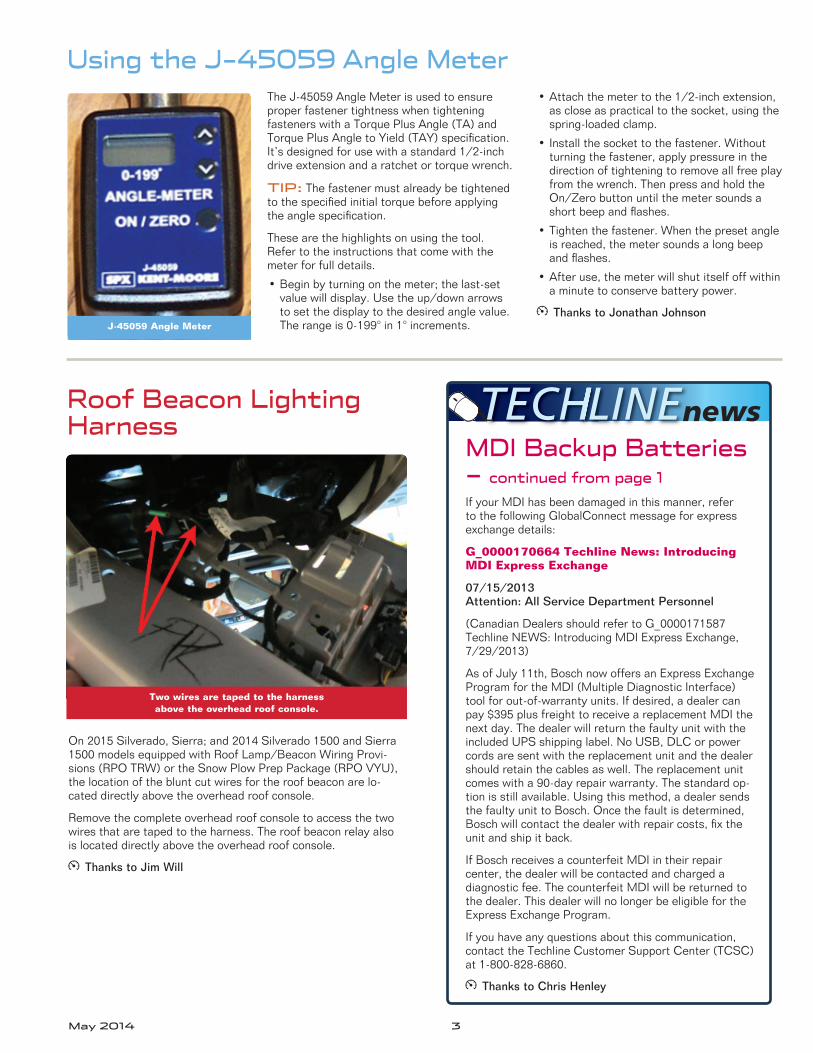
The J-45059 Angle Meter is used to ensure proper fastener tightness when tightening fasteners with a Torque Plus Angle (TA) and Torque Plus Angle to Yield (TAY) specification. It’s designed for use with a standard 1/2-inch drive extension and a ratchet or torque wrench.
TIP: The fastener must already be tightened to the specified initial torque before applying the angle specification.
These are the highlights on using the tool. Refer to the instructions that come with the meter for full details.
• Begin by turning on the meter; the last-set value will display. Use the up/down arrows to set the display to the desired angle value. The range is 0-199° in 1° increments.
• Attach the meter to the 1/2-inch extension, as close as practical to the socket, using the spring-loaded clamp.
• Install the socket to the fastener. Without turning the fastener, apply pressure in the direction of tightening to remove all free play from the wrench. Then press and hold the On/Zero button until the meter sounds a short beep and flashes.
• Tighten the fastener. When the preset angle is reached, the meter sounds a long beep and flashes.
• After use, the meter will shut itself off within a minute to conserve battery power.
Thanks to Jonathan Johnson
Roof Beacon Lighting Harness
On 2015 Silverado, Sierra; and 2014 Silverado 1500 and Sierra 1500 models equipped with Roof Lamp/Beacon Wiring Provi-sions (RPO TRW) or the Snow Plow Prep Package (RPO VYU), the location of the blunt cut wires for the roof beacon are lo-cated directly above the overhead roof console.
Remove the complete overhead roof console to access the two wires that are taped to the harness. The roof beacon relay also is located directly above the overhead roof console.
Thanks to Jim Will
J-45059 Angle Meter
Two wires are taped to the harness above the overhead roof console.
4 May 2014
Heated Seat May Turn Off
A/C Tube Repair Kits for Auxiliary A/C and Heater Pipes
Backup Camera InoperativeOn some 2014 Corvettes
built prior to April 5, 2014, the heated seat may turn off within a few minutes of being turned on. It can be turned on again, but may turn off again by itself. This condition may be intermittent, depend-ing on the seat's position. DTC U1524 (Lost Commu-nication with Seat Heating Control Module) also may be set.
This condition may be caused by a pinched wire in the seat assembly. Inspect the seat cushion and seat back heater element harnesses near the rear inboard corner of the seat assembly. It may be difficult to access this area without first removing the seat assembly from the vehicle.
If the harness is pinched, repair the wiring, reroute the harness and use a tie strap to hold the harness away from any pinch points.
Thanks to Jeremy Richardson
New A/C Tube Repair Kits are now available as an alternative repair tech-nique to using a J-41425 A/C Line Repair Kit to repair auxiliary air conditioning and heater pipes. The kits can be used when there is rub-through damage, collision damage or leaking in the A/C or heater lines.
Starting with the 2015 model year full-size SUVs, vehicle specific repair kits will exist in the Electronic Parts Catalog (EPC). Detailed repair instructions are available for 2015 model year full-size SUVs in the appropriate Service Information (Reference Document ID # 3535636 in HVAC Repair sections).
The A/C Tube Repair Kits require a specific length of tube/pipe be removed to accommodate the length added by the coupler body. The length removed at the service cut location varies for each kit size. Only use the A/C Tube Repair Kits on straight sections that are long enough to accommodate the coupler length.
Thanks to Chris Semanisin, Frank Rogers, and Larry Kasperek
The Rear Vision Camera (RPO UVC) may be inopera-tive on some 2013-2014 Malibu models.
When diagnosing this condition, first verify that connector X220 is properly connected. Connector X220 is a black 16-way connector located behind the passenger kick panel. It may have as few as 3 wires or up to 13 wires in the connector.
Secure the connector and check the operation of Rear Vision Camera.
Thanks to Christopher CrumbReroute the harness and move it away from any pinch points.
Connector X220
Fuel fill valveHeater element harnesses near the rear inboard corner of
the seat assembly
A/C Tube Repair Kit
A/C Tube Repair Kits Part Numbers and Specifications
Part NumberKit Size/
Pipe “Outside Diameter”
Pipe Length Removed to Install Kit Coupler
Required Torque for Kit Coupler Nuts
19194702 5/16 in 4 mm20-24 Nm
(15-18 lb ft)
19194701 3/8 in 7 mm20-24 Nm (15-18 lb ft)
19194700 1/2 in 10 mm20-24 Nm (15-18 lb ft)
19188253 5/8 in 11 mm24-27 Nm (18-20 lb ft)
88878215 3/4 in 31 mm24-27 Nm (18-20 lb ft)
13590410 8 mm 4 mm20-24 Nm (15-18 lb ft)
88878216 10 mm 4 mm20-24 Nm (15-18 lb ft)
88878217 12 mm 10 mm20-24 Nm (15-18 lb ft)
88878218 16 mm 11 mm24-27 Nm (18-20 lb ft)
May 2014 5
CTS Hazard Flashers Switch Operation Update
New 15-Digit Battery Warranty Code
A BCM calibration has changed the operation of the hazard flashers switch on 2014 CTS sedan models produced after October 11, 2013, or any vehicle that has had the BCM programmed during service. After the calibration update, the hazard flashers switch must be pressed and held for one second before the hazard flashers will operate.
The hazard flashers also need a one second all clear status to change states. This means in order to turn off the hazard flash-ers, you must to remove your finger from the hazard switch for at least one second and then press the switch again for one second. If you do not remove your finger for at least one second, the system determines that the switch is still being pressed.
Thanks to Jean Hart and Stephen Jacob
A warranty code is required for all batteries replaced under warranty. The code is generated by the Midtronics GR8 Battery Tester/Charger (EL-50313), which now captures additional information in the expanded 15-digit code. The software of the tester/charger must be up-dated. The latest software release is available on the GM Dealer Equipment website (U.S.) at www.gmdesolutions.com. In Canada, go to www.des-canada.ca.
Warranty codes are generated only when the battery test is set up as follows on the tool:
• Select Diagnostic Mode
• Select Out Of Vehicle
• Replace decision is the test result
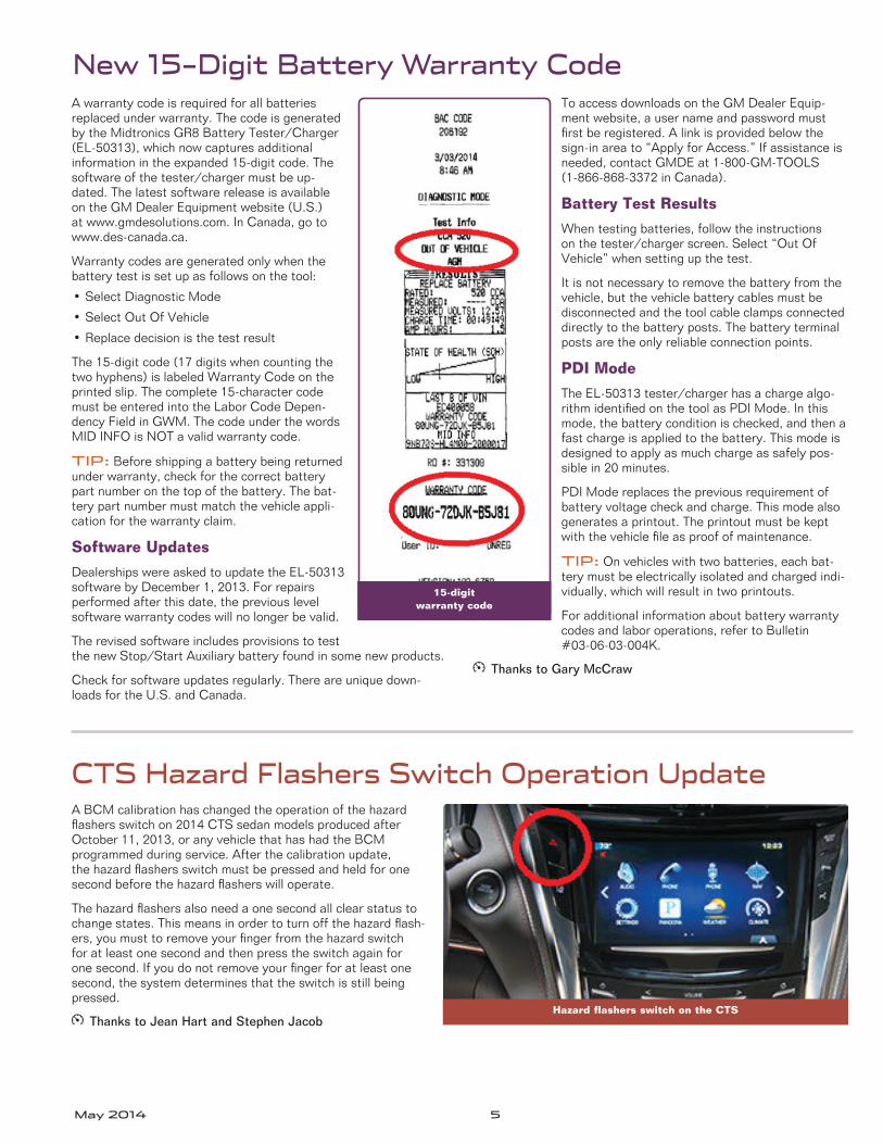
The 15-digit code (17 digits when counting the two hyphens) is labeled Warranty Code on the printed slip. The complete 15-character code must be entered into the Labor Code Depen-dency Field in GWM. The code under the words MID INFO is NOT a valid warranty code.
TIP: Before shipping a battery being returned under warranty, check for the correct battery part number on the top of the battery. The bat-tery part number must match the vehicle appli-cation for the warranty claim.
Software Updates
Dealerships were asked to update the EL-50313 software by December 1, 2013. For repairs performed after this date, the previous level software warranty codes will no longer be valid.
The revised software includes provisions to test the new Stop/Start Auxiliary battery found in some new products.
Check for software updates regularly. There are unique down-loads for the U.S. and Canada.
To access downloads on the GM Dealer Equip-ment website, a user name and password must first be registered. A link is provided below the sign-in area to “Apply for Access.” If assistance is needed, contact GMDE at 1-800-GM-TOOLS (1-866-868-3372 in Canada).
Battery Test Results
When testing batteries, follow the instructions on the tester/charger screen. Select “Out Of Vehicle” when setting up the test.
It is not necessary to remove the battery from the vehicle, but the vehicle battery cables must be disconnected and the tool cable clamps connected directly to the battery posts. The battery terminal posts are the only reliable connection points.
PDI Mode
The EL-50313 tester/charger has a charge algo-rithm identified on the tool as PDI Mode. In this mode, the battery condition is checked, and then a fast charge is applied to the battery. This mode is designed to apply as much charge as safely pos-sible in 20 minutes.
PDI Mode replaces the previous requirement of battery voltage check and charge. This mode also generates a printout. The printout must be kept with the vehicle file as proof of maintenance.
TIP: On vehicles with two batteries, each bat-tery must be electrically isolated and charged indi-vidually, which will result in two printouts.
For additional information about battery warranty codes and labor operations, refer to Bulletin #03-06-03-004K.
Thanks to Gary McCraw
Hazard flashers switch on the CTS
15-digit warranty code
6 May 2014
Cracks, chips, scratches, breaks and other damage to headlamps, tail lamps and other exterior lights are often the result of an impact with a road hazard or improper maintenance. These condi-tions are not covered under the GM New Vehicle Warranty. Two bulletins have recently been updated recently regarding lamp damage (Bulletin #02-08-42-001F) and lamp condensation (Bulletin #01-08-42-001I).
Chemical Damage
On most late model vehicles, headlamp and license lamp lenses are made of poly-carbonate, due to its high temperature and impact resistance. Polycarbonates can be damaged, crazed or cracked by improper contact with various chemicals:
• Cleaners used to remove rail dust
• Rubbing compounds
• Grease/tar/oil removers
• Tire cleaners
• Prep solvents
• Cleaners/waxes
• Undiluted washer solvent
• Alcohol
• Concentrated car wash soaps
Only lukewarm or cold water, a soft cloth and car washing soap should be used to clean exterior lamps and lenses.
Overheating Damage
Overheating most often appears as imperfections in the lens surface. This results from restricting the amount of heat that the lamp can dissipate.
Avoid covering headlamps with shop mats or fender covers if the vehicle is being serviced with the headlamps or DRLs illuminated. This can cause crazing and deformation due to overheating; the re-sults may be immediate or may eventually appear as hairline cracks.
Another trend being seen is the installa-tion of headlamp or fog lamp bulbs that have a higher output than the original equipment. Because the bulb output is higher, the operating temperature is also higher. This excessive heat can melt the socket, housing, or lens. The bulb number should match the GM service part.
Impact Damage
Impact damage is often indicated by the assembly holding moisture, being inopera-tive, or blemished.
Polycarbonate headlamp lenses are very tough and will withstand normal stone strikes without damage. They are also tough enough not to show witness marks of impacts severe enough to damage the rear housing. This damage is often revealed through close visual inspection once the lamp is removed. Broken mount-ing tabs, rear housing fractures, and loose components inside the lamp assembly are evidence of impact damage.
When encountering these concerns, never assume it will automatically be a warranty repair. Inspection of the lamp assembly, once removed from the vehicle, is required to assess warrantability.
Lamp Condensation
A distinction is made between a lamp with condensation and a lamp with a water leak. Condensation appears in a lamp as very small droplets of water, a fine mist, or a white fog on the inside of the lens. It oc-curs when the air inside the lens reaches the "dew point." This is the temperature at which the humidity in the air is cooled enough to become liquid. The most preva-lent time of the year for fogging to occur is in the spring and fall.
Most exterior lamps on GM vehicles are designed to expel accumulated vapor through a vent system. Although the vent system operates at all times, it is most effective when the lamp is on and the vehicle is moving.
The amount of time required for the lamp to clear may vary from two to six hours. Customers with short commutes will expe-rience a longer time to clear the lamp.
If these conditions are noted, advise the customer that replacing a lamp assembly may not correct this condition.
Typically, the condensation is located primarily in the lens corners (near the vents) and does not cover more than half of the lens surface. The condition should clear of moisture when the vehicle is parked in a dry environment, or when the vehicle is driven with the lights on.
Water Leak
A water leak is evidenced by numerous drops of water in various sizes, collect-ing on the inside surface of the lamp lens after the vehicle has been exposed to rain or a car wash.
A water leak condition will cover more than half the surface of the lamp lens. In addition, there may be an accumula-tion of water in the bottom of the lamp assembly. This condition will not clear when the vehicle is parked in a dry en-vironment, or when the vehicle is driven with the lights on.
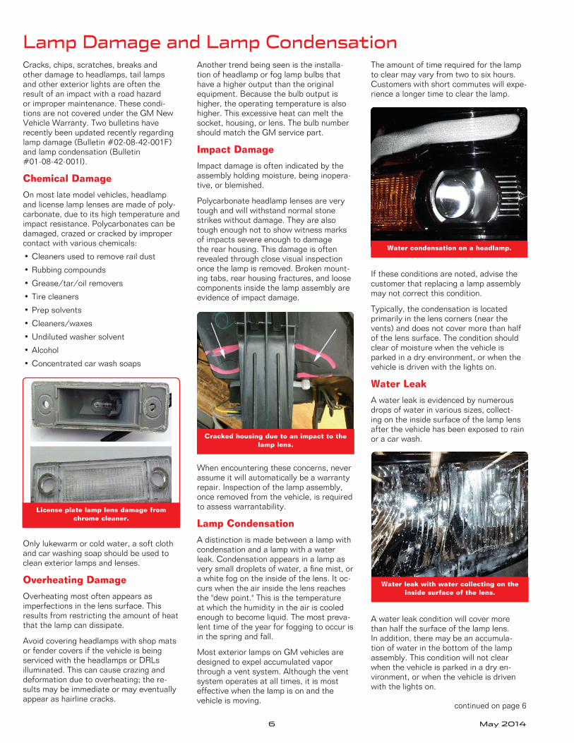
License plate lamp lens damage from chrome cleaner.
Cracked housing due to an impact to the lamp lens.
Water leak with water collecting on the inside surface of the lens.
Water condensation on a headlamp.
Lamp Damage and Lamp Condensation
continued on page 6
May 2014 7
Lamp Damage and Lamp Condensation — continued from page 6
Lamp Service Tips
When diagnosing or repairing a lamp for condensation or a leak:
• Do not replace lamps for fogging.
• Do not modify the lamp housing, such as drilling holes.
• Do not use the incorrect bulbs for the application, which may damage the housing and connector.
• Cold water in a car wash on a hot day may cause headlamp fogging.
• Use care when removing and installing lenses to prevent damage to the hous-ing and mounting tabs.
For example, on the 2014-2015 Silverado 1500 and Sierra 1500 trucks, when remov-ing and installing the tail lamps, do not apply excessive pressure to the lamp lens using your thumbs. Use your palms to pull
or push the lamp. Applying too much pres-sure on the lens can cause the housing to crack behind the reflector field of the lamp.
When servicing any exterior lighting as-sembly, be sure to transfer electrical connection seals to the new part. They are often on the body side of the harness connection, but may have stayed on the part being replaced. If not transferred to the new part, the connection may corrode due to water entry.
Use of Non-GM Lamps
Many aftermarket companies manufacture lamp assemblies that look very similar to the original equipment (OE). Non-OE lamps may be installed on vehicles as part of a collision repair.
If these lamps are holding moisture or the bulbs are inoperative due to corroded elec-trical connections, they are not covered by
the New Vehicle Warranty. Check for the GM trademark on the part label. Not all lamp assemblies currently have the trade-mark, but future assemblies will contain the trademark on the label.
Parts without the GM trademark are not eligible for replacement under warranty.
Thanks to Gary McCraw
Look for the GM trademark on the part label.
Brake Noise during Slow StopsWhen applying the brakes on the 2014 Camaro Z/28 during a slow stop, a growl noise may be heard coming from the front or rear brakes.
Some noise is normal with all braking systems and differences in loading, type of driving, or driving style can make a difference in brake wear on the same make and model vehicle. Depending on weather conditions, driving patterns, and the local environment, brake noise may become more or less apparent. First, verify that all metal-to-metal contact areas between pads, pad guides,
calipers, and knuckles are clean. Brake noise also may be caused by a “slip-stick” vibration of brake components.
With the Camaro Z/28’s high performance braking system, it may exhibit more noise at slower speeds than a conventional braking system. This is considered a normal characteristic of the vehicle and, typically, no repairs are needed for these types of noises.
If the noise condition can be duplicated after the initial inspec-tion, and the cause cannot be attributed to the previously men-tioned items, burnish the brakes on the vehicle and evaluate the condition.
Follow the brake burnishing procedure listed in the Owner's Manual, beginning on page 9-8. The procedure for the Camaro Z/28 is different than the procedure for the Camaro ZL1 and the Camaro SS equipped with the 1LE "Track Package".
TIP: The Camaro Z/28 uses Brembo® Carbon Ceramic-Matrix™ rotors, which is part of an entirely different type of braking sys-tem than the other Camaro models. If the incorrect procedure is followed, damage to the braking system/vehicle may result.
The brake burnishing procedure for the Camaro Z/28 model is a two-part procedure. The first part is intended for street driving only. If the customer will only be driving the vehicle on regular city streets, this procedure is all that is required. If the customer plans on preparing the vehicle for driving on a track, the Street Brake Burnishing procedure should be completed first, followed immedi-ately by the Racing/Track Brake Burnishing procedure.
Thanks to Matt Bierlein
Camaro Z/28 carbon ceramic rotors
8 May 2014
GM TechLink is published for all GM retail technicians and service consultants to provide timely information to help increase know ledge about GM products and improve the performance of the service department.
Publisher:John Meade GM Customer Care and Aftersales
Editor:Lisa G. Scott GM Customer Care and Aftersales
GM TechLink on the Web: : GM GlobalConnectGeneral Motors service tips are intended for use by professional technicians, not a “do-it-yourselfer.” T hey are written to inform those technicians of conditions that may occur on some vehicles, or to provide information that could assist in the proper service of a vehicle. Properly trained technicians have the equipment, tools, safety instructions and know-how to do a job properly and safely. If a condition is described, do not assume that the information applies to your vehicle or that your vehicle will have that condition. See a General Motors dealer servicing your brand of General Motors vehicle for information on whether your vehicle may benefit from the information.Inclusion in this publication is not necessarily an endorsement of the individual or the company.
Rechargeable Energy Storage System Smoke TestingAny time internal battery service is per-formed on the 2011-2014 Volt and 2014 ELR, a smoke test should be performed on the rechargeable energy storage system following the appropriate Service Informa-tion procedures.
A smoke test is critical to ensuring the integrity and proper operation of the high voltage battery pack and housing. For example, if the weather pack connections (housing) are damaged, a smoke test will identify any broken electrical connections. A damaged connector, as shown, could —impact the weatherpack seal and allow moisture inside the battery pack.
TIP: Always perform the High Voltage Disabling procedure prior to servicing any high voltage component or connection. Personal Protection Equipment (PPE) and proper procedures must be followed.
The test requires Battery Smoke Test Leak Adapters (EL-50812) and the Evaporative Emissions System Tester (GE 41413-A). The Battery Smoke Test Leak Adapters should be installed to all of the Recharge-able Energy Storage System electrical connectors. The Evaporative Emissions System Tester hose is installed to the bat-tery Rechargeable Energy Storage System adapter to inject smoke into the battery.
TIP: Only nitrogen is approved to gen-erate smoke for EV battery leak testing. Compressed air should not be used. The GE-41413-A tester uses nitrogen and the fittings are designed to not allow it to be connected to compressed air in the shop.
Once the Rechargeable Energy Storage System is filled with smoke, use a high-intensity white light to look for any visible smoke emitting from the system. Repair any visible leaks by retightening the fasteners or resealing any areas using butyl sealant. Refer to the Rechargeable Energy Storage System Smoke Test in the ap-propriate Service Information for complete repair information.
In addition, always follow the procedures for properly removing the cables from the Drive Motor Battery, including the Body Harness Connector and Interlock Loop Connectors. Wrap the exposed electrical connections with electrical tape to keep coolant out of the connections.
Thanks to Keith Newbury
Any damage to the housing could impact the weatherpack seal.
Tester hose installed to the Rechargeable Energy Storage System adapter.
A. Body Harness Connector B. Interlock Loop Connector
May 2014 9
Corvette Driver Mode ControlThe different driver modes on the 2014 Corvette provide enhanced performance for different driv-ing conditions by changing the throttle progres-sion, shift mode, steering assist, limited slip differ-ential, ride control, traction control, exhaust sound and other calibra-tions. There are five driver modes that can be selected using the Driver Mode Control located on the center console: Weather, Eco, Tour, Sport, and Track.
If the vehicle was in Weather or Track mode during the previ-ous drive cycle, it will default to the Tour mode the next time the vehicle is turned on. This is design intent. No repairs should be performed.
It is important to understand that the display themes on the instru-ment cluster and drive modes are two separate items that can be
linked together or selected separately. When linked, the instrument cluster dis-play theme is configured for the selected drive mode — Weather, Eco, Tour modes: Tour theme; Sport mode: Sport theme; and Track mode: Track theme.
If a specific display theme for all drive modes is desired, or to have the display theme change each time a drive mode is changed, use the DIC Settings menu to select Link to Drive Mode – Track, Sport, or Tour for the cluster theme.
Regardless of the Display Theme setting, the drive mode will al-ways default to Tour if the vehicle is turned off in the Weather or Track mode.
Thanks to Jeremy Richardson
Driver Mode Control on the center consoleThe Display Theme on the gauge cluster can be
linked to the Drive Mode.
Service
Know-How
10214.05D Emerging Issues
To view Emerging Issues seminars:• Log in to www.centerlearning.com
– Select Resources, and then Video on Demand; or – Select Catalog to search for the course number, and then
select View > Take or Continue Course
May 8, 2014
10 May 2014
Truck Issues – Fix It Right the First Time
Model Year(s) Vehicle Line(s)/Condition Do This Don’t Do This
Reference Information/
Bulletin
2014-2015 Sierra, Silverado — Difficult to engage clamp(s) when installing soft roll-up tonneau cover
Apply a thin coating of GM SuperLube or remove 2 mm of seal from the clamp.
Force clamps to shut or replace entire tonneau cover for this condition.
PI0970A
2010-2014 SRX, Terrain, Equinox — Diagnosing and repairing power liftgate operation
Check the right side gas strut for signs of wear, cracks, leaks or other damage and replace as necessary.
Replace the left side power liftgate hydraulic actuator arm or the liftgate hydraulic pump or motor assembly without proper diagnosis.
PI1186
2013-2015 Encore — Poor Remote Keyless Entry transmitter range
Relocate antenna receiver module from left rear quarter panel to adjacent trim.
Replace antenna receiver module. PI1209
2014 Sierra, Silverado — Illumination of rings around volume, menu and temperature knobs of center stack
Use the table listed to verify expected operation.
Don't compare to early marketing graphics, various build dates or models as there have been running changes.
PI1174A
2014 Sierra, Silverado — Exhaust rattle, buzz, pop or whistle
Follow the diagnostic aids. Replace exhaust before noise is verified. PI1201A
2014-2015 Tahoe, Suburban, Silverado, Sierra, Yukon XL, Yukon — Intermittent no start, Security lamp illuminated, DTCs B3935 and B2955 set
Reprogram BCM ONLY in the event of Security system codes.
Reprogram BCM for any no-start issues that do not include the B3935 or B2955 malfunction codes.
PI1180A
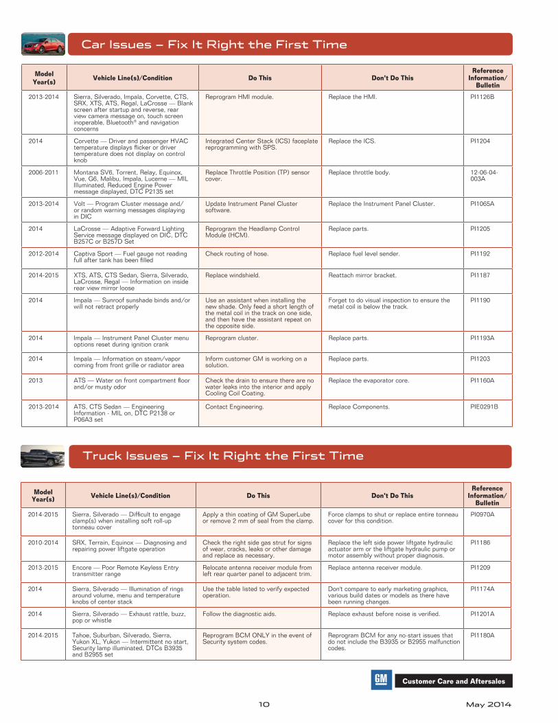
Car Issues – Fix It Right the First Time
Model Year(s) Vehicle Line(s)/Condition Do This Don’t Do This
Reference Information/
Bulletin
2013-2014 Sierra, Silverado, Impala, Corvette, CTS, SRX, XTS, ATS, Regal, LaCrosse — Blank screen after startup and reverse, rear view camera message on, touch screen inoperable, Bluetooth® and navigation concerns
Reprogram HMI module. Replace the HMI. PI1126B
2014 Corvette — Driver and passenger HVAC temperature displays flicker or driver temperature does not display on control knob
Integrated Center Stack (ICS) faceplate reprogramming with SPS.
Replace the ICS. PI1204
2006-2011 Montana SV6, Torrent, Relay, Equinox, Vue, G6, Malibu, Impala, Lucerne — MIL Illuminated, Reduced Engine Power message displayed, DTC P2135 set
Replace Throttle Position (TP) sensor cover.
Replace throttle body. 12-06-04-003A
2013-2014 Volt — Program Cluster message and/or random warning messages displaying in DIC
Update Instrument Panel Cluster software.
Replace the Instrument Panel Cluster. PI1065A
2014 LaCrosse — Adaptive Forward Lighting Service message displayed on DIC, DTC B257C or B257D Set
Reprogram the Headlamp Control Module (HCM).
Replace parts. PI1205
2012-2014 Captiva Sport — Fuel gauge not reading full after tank has been filled
Check routing of hose. Replace fuel level sender. PI1192
2014-2015 XTS, ATS, CTS Sedan, Sierra, Silverado, LaCrosse, Regal — Information on inside rear view mirror loose
2014 Impala — Sunroof sunshade binds and/or will not retract properly
Use an assistant when installing the new shade. Only feed a short length of the metal coil in the track on one side, and then have the assistant repeat on the opposite side.
Forget to do visual inspection to ensure the metal coil is below the track.
PI1190
2014 Impala — Instrument Panel Cluster menu options reset during ignition crank
Reprogram cluster. Replace parts. PI1193A
2014 Impala — Information on steam/vapor coming from front grille or radiator area
Inform customer GM is working on a solution.
Replace parts. PI1203
2013 ATS — Water on front compartment floor and/or musty odor
Check the drain to ensure there are no water leaks into the interior and apply Cooling Coil Coating.
Replace the evaporator core. PI1160A
2013-2014 ATS, CTS Sedan — Engineering Information - MIL on, DTC P2138 or P06A3 set