34
Mc Propeller Flowmeters Installation, Operation And Maintenance Manual 24517-11 Rev. 4.0 November, 2013

Mc Propeller Flowmeters
Installation, Operation AndMaintenance Manual
24517-11 Rev. 4.0November, 2013

TABLE OF CONTENTS
1.0 INTRODUCTION ............................................................................................................................................ 1 1.1 MODEL TYPES ............................................................................................................................................................................. 1 1.2 TYPICAL APPLICATIONS .......................................................................................................................................................... 1
2.0 SPECIFICATIONS ........................................................................................................................................... 2 2.1 GENERAL SPECIFICATIONS ................................................................................................................................................... 2 2.2 HOW TO READ A TOTALIZER .................................................................................................................................................. 2 2.3 UNDERSTANDING THE REGISTER GEAR RATIO ................................................................................................................ 3 2.4 ACCURACY ................................................................................................................................................................................... 4 2.5 HEADLOSS ................................................................................................................................................................................... 4
3.0 INSTALLATION INSTRUCTIONS .................................................................................................................. 5 3.1 SAFETY .......................................................................................................................................................................................... 5 3.2 STRAIGHTENING VANES ........................................................................................................................................................ 5 3.3 INSTALLATION CONSIDERATIONS ....................................................................................................................................... 5 3.4 PIPE RUN REQUIREMENTS .................................................................................................................................................... 6 3.5 FLOW DIRECTION ...................................................................................................................................................................... 7
4.0 METER CONSTRUCTION .............................................................................................................................. 7 4.1 COMMON PARTS ...................................................................................................................................................................... 7 4.2 PROPELLER .................................................................................................................................................................................. 8 4.3 BEARING ASSEMBLY ................................................................................................................................................................. 8 4.4 DRIVE ASSEMBLY ....................................................................................................................................................................... 9 4.5 METERHEAD ................................................................................................................................................................................ 9 4.6 REGISTER EXTENSION ............................................................................................................................................................10
5.0 MAINTENANCE AND TROUBLESHOOTING .............................................................................................. 11 5.1 OCCASIONAL INSPECTIONS ................................................................................................................................................11 5.2 TOOLS LIST .................................................................................................................................................................................11 5.3 DISASSEMBLY AND INSPECTION PROCEDURE .............................................................................................................12 5.4 ORDERING REPLACEMENT PARTS .....................................................................................................................................13 5.5 REASSEMBLY PROCEDURE ...................................................................................................................................................14
6.0 TECHNICAL SPECIFICATIONS .................................................................................................................... 14
TECHNICAL SUPPORT ....................................................................................................................................... 14
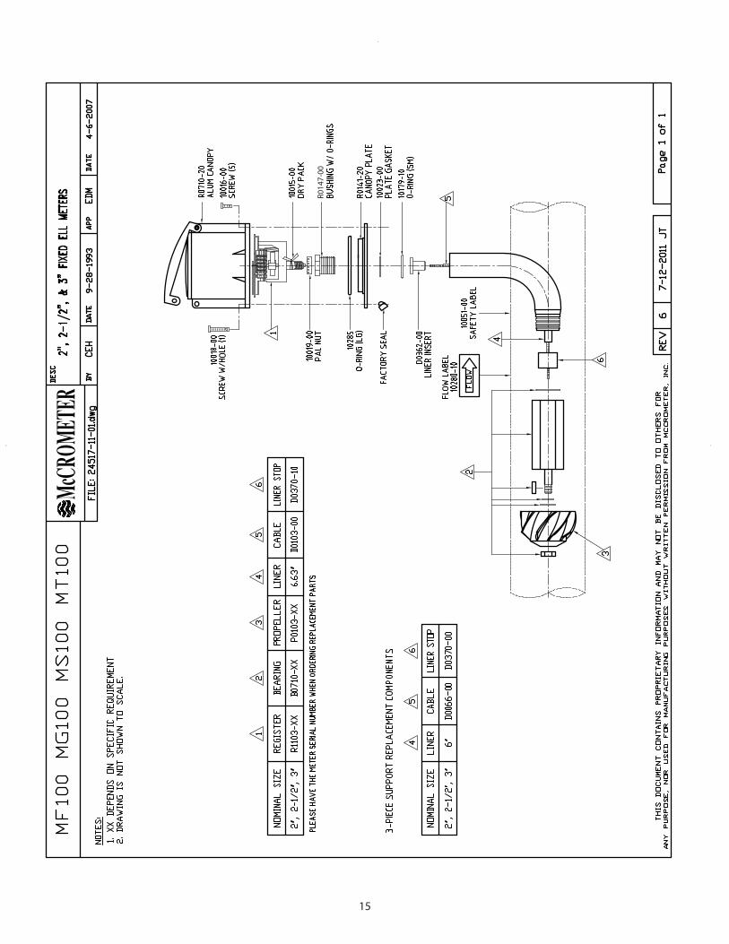
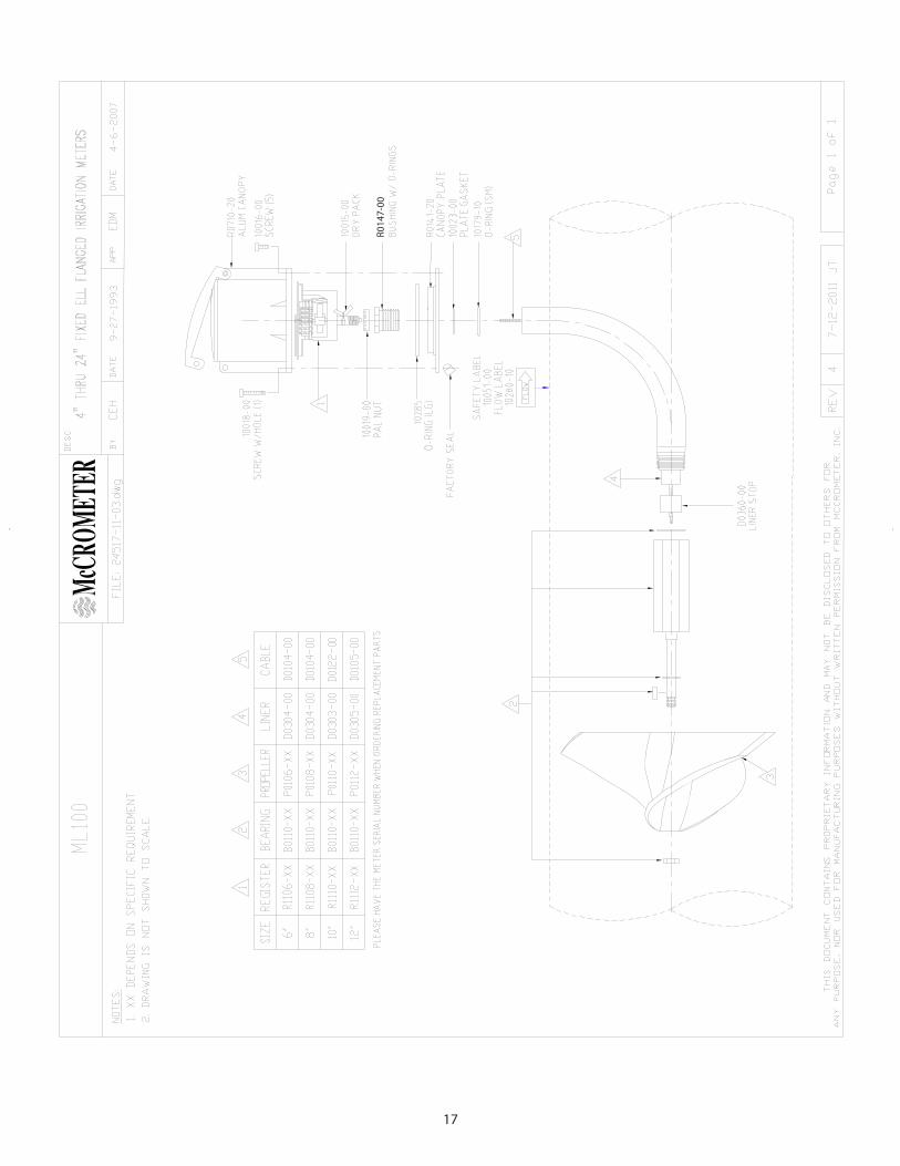
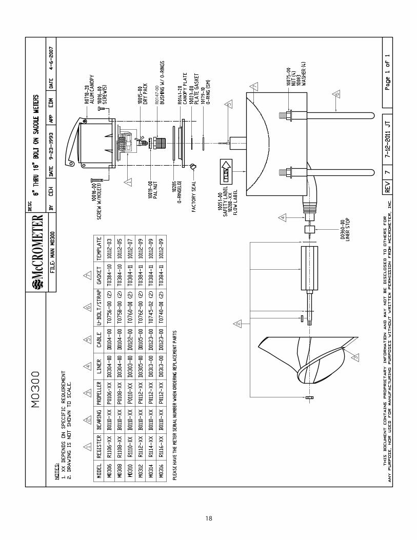
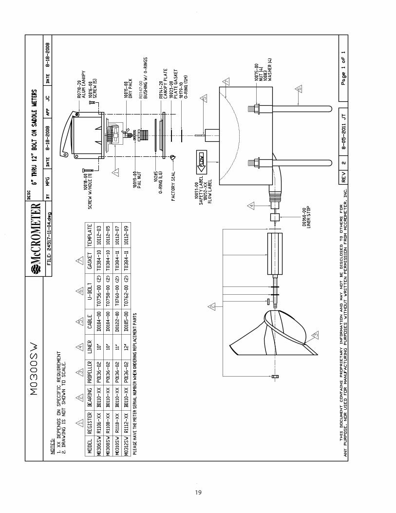
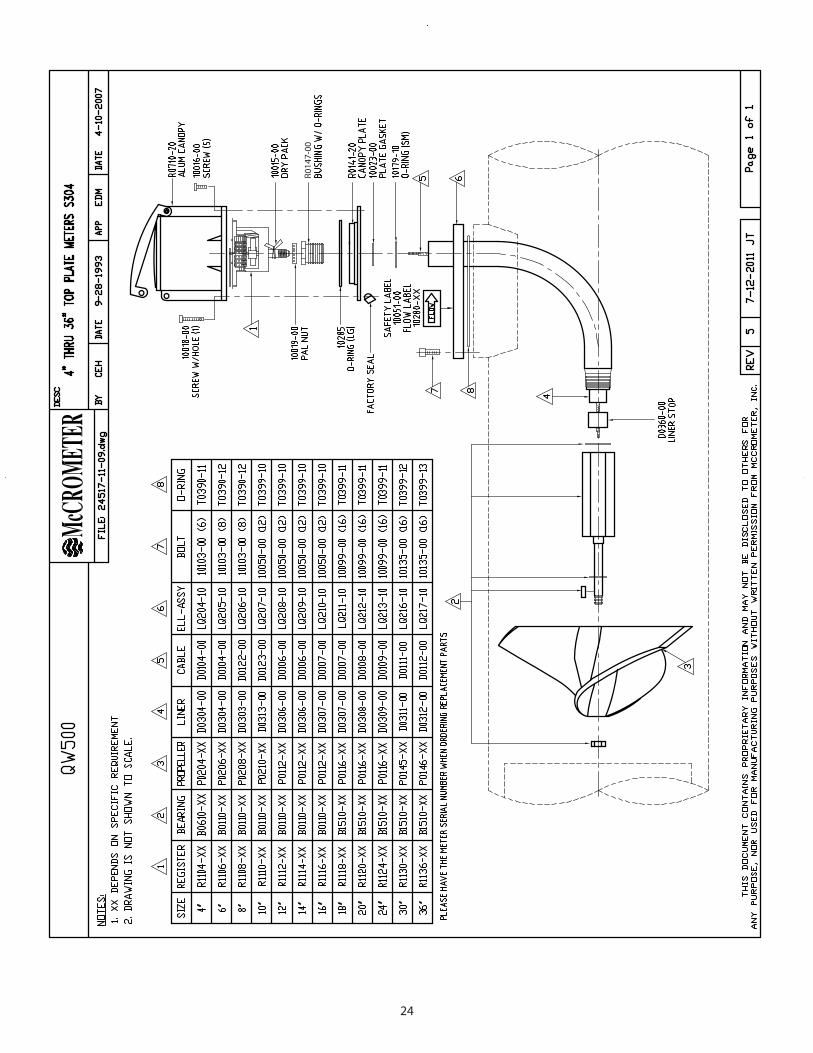
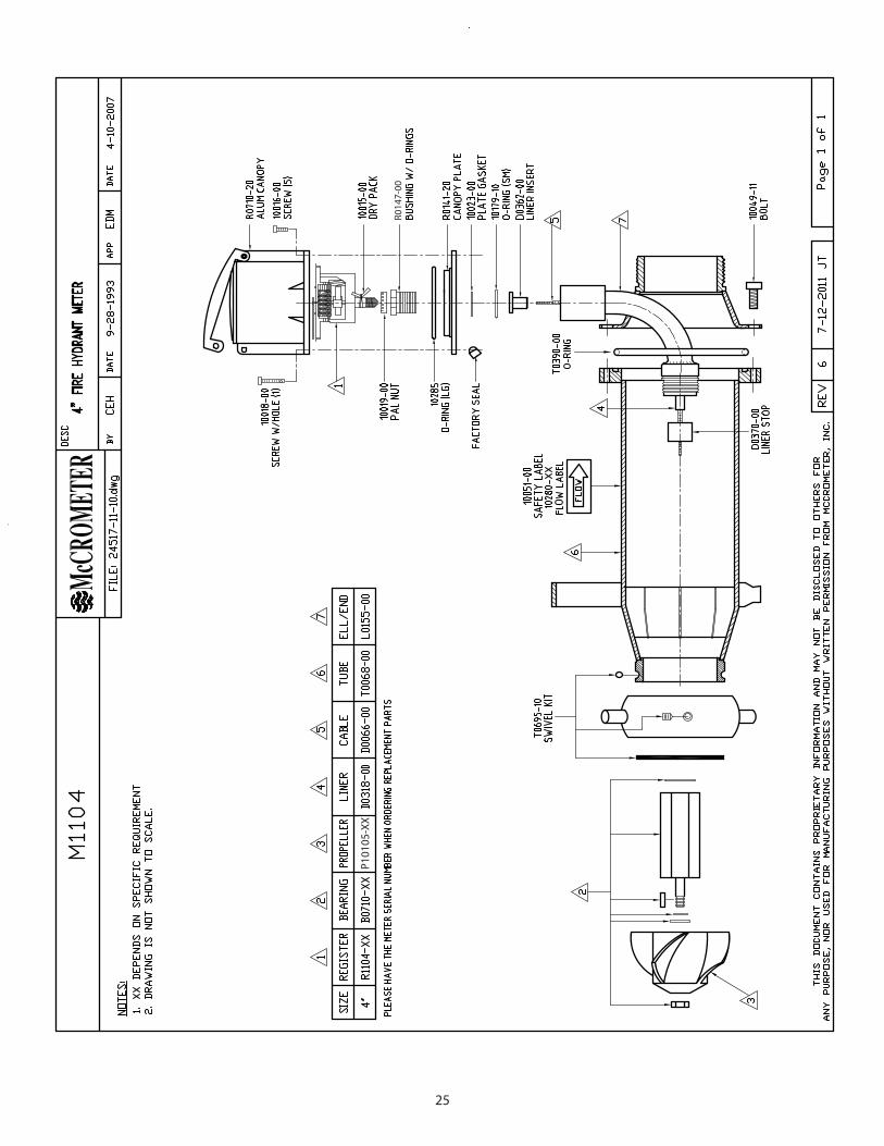
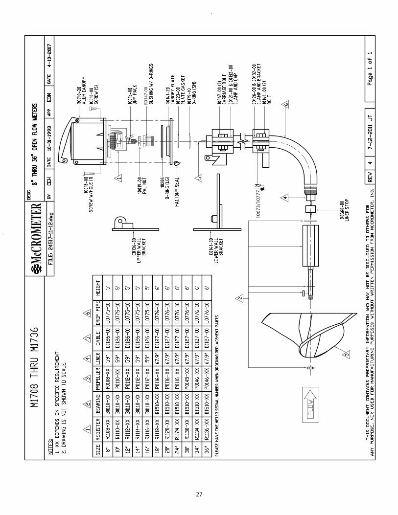
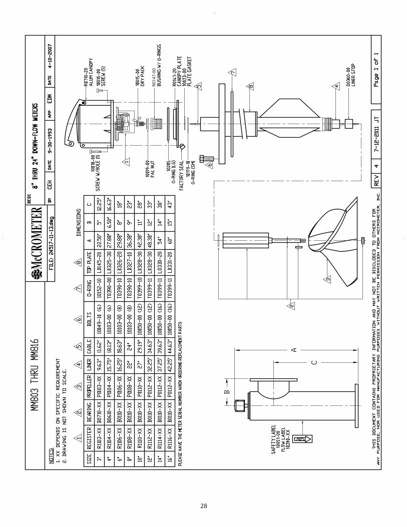
METER MODEL DRAWINGS .............................................................................................................................. 15 MF100, MG100, MS100. MT100 2” - 3” .....................................................................................................................................15 MF100, MZ100, MZ200, MG100, MS100, MT104, MT106 4” - 24” ..................................................................................16 ML100..................................................................................................................................................................................................17 M0300 .................................................................................................................................................................................................18 M0300SW ...........................................................................................................................................................................................19 M0304 .................................................................................................................................................................................................20 MW/QW500, MG900, MT900, MW900 2” - 3” ........................................................................................................................21 MW500, MW600, MG/MW900, MT904, MT906 4” - 24” .....................................................................................................22 MZ500 .................................................................................................................................................................................................23 QW500 ................................................................................................................................................................................................24 M1104 .................................................................................................................................................................................................25 M1400 .................................................................................................................................................................................................26 M1708 THROUGH M1736 ............................................................................................................................................................27 MM803 THROUGH MM816 .........................................................................................................................................................28 MW803 THROUGH MW824 .........................................................................................................................................................29WARRANTY ........................................................................................................................................................ 30
Copyright © 1997-2013 McCrometer, Inc. All printed material should not be changed or altered without permission of McCrometer. Any published technical data and instructions are subject to change without notice. Contact your McCrometer representative for current technical data and instructions. Mc® of Mc Propeller is a registered trademark of McCrometer, Inc.
www.mccrometer.com Lit. #24517-11 Rev. 4.0/11-13
1
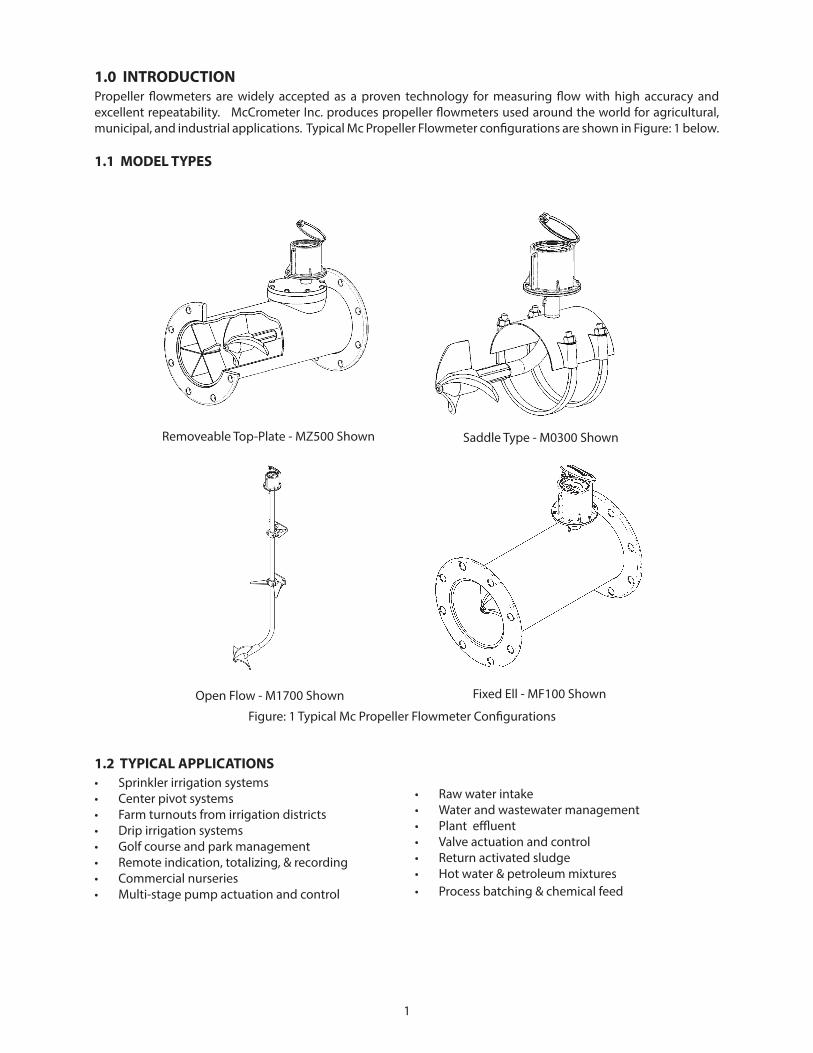
1.0 INTRODUCTIONPropeller flowmeters are widely accepted as a proven technology for measuring flow with high accuracy and excellent repeatability. McCrometer Inc. produces propeller flowmeters used around the world for agricultural, municipal, and industrial applications. Typical Mc Propeller Flowmeter configurations are shown in Figure: 1 below.
1.1 MODEL TYPES
Removeable Top-Plate - MZ500 Shown Saddle Type - M0300 Shown
Open Flow - M1700 Shown Fixed Ell - MF100 Shown
Figure: 1 Typical Mc Propeller Flowmeter Configurations
1.2 TYPICAL APPLICATIONS• Sprinkler irrigation systems • Center pivot systems • Farm turnouts from irrigation districts • Drip irrigation systems• Golf course and park management • Remote indication, totalizing, & recording • Commercial nurseries • Multi-stage pump actuation and control
• Raw water intake • Water and wastewater management • Plant effluent• Valve actuation and control• Return activated sludge • Hot water & petroleum mixtures• Process batching & chemical feed
2
2.0 SPECIFICATIONSThe measuring element of a propeller flowmeter consists of a rotating device, called a rotor or propeller. Positioned in the center of the flowstream, the propeller rotates at a rate proportional to the velocity of the fluid through the flowmeter. This rotation can be transmitted mechanically to a register assembly and the fluid’s volumetric flowrate and accumulated volume can then be displayed.
2.1 GENERAL SPECIFICATIONSDESCRIPTIONS:TURNDOWN: Propeller meters are specified to work within a certain range of flowrates. Turndown is the ratio of the maximum flowrate to the minimum flowrate of the meter. A typical turndown of an 8” meter is 15:1. (e.g., max. flow = 1500 gpm to min. flow = 100 gpm)
ACCURACY: Accuracy is the relation between the volume shown on the meter’s totalizer and the actual volume of fluid which has passed through the meter. McCrometer guarantees that the meter will report within ±2% of the actual flow if it is normally operated between its minimum and maximum rates of flow.
REPEATABILITY: Flowmeter repeatability is the ability of a meter to reproduce a measurement under similar conditions. This is not by itself a measure of accuracy, but rather a component of the meter's total accuracy. McCrometer propeller meters have a repeatability of ±0.25%.
PRESSURE: The pressure rating for standard propeller meters is 150 PSI. This pressure rating refers to the constant line pressure in the pipe. Some models can be rated up to 300 PSI. Higher pressures are available on special request.
TEMPERATURE: The temperature rating for standard propeller meters is 160° F constant temperature. This temperature rating refers to fluid temperature. Most standard models can be upgraded to 180° F constant temperature on special request.
SIZES AVAILABLE 2” to 96”
FLOWRATES AVAILABLE 40 to 75,000 GPM
TURNDOWN up to 15:1
ACCURACY ±2%
REPEATABILITY ±0.25%
RATED PRESSURE 150 PSI
RATED TEMPERATURE 160o
F
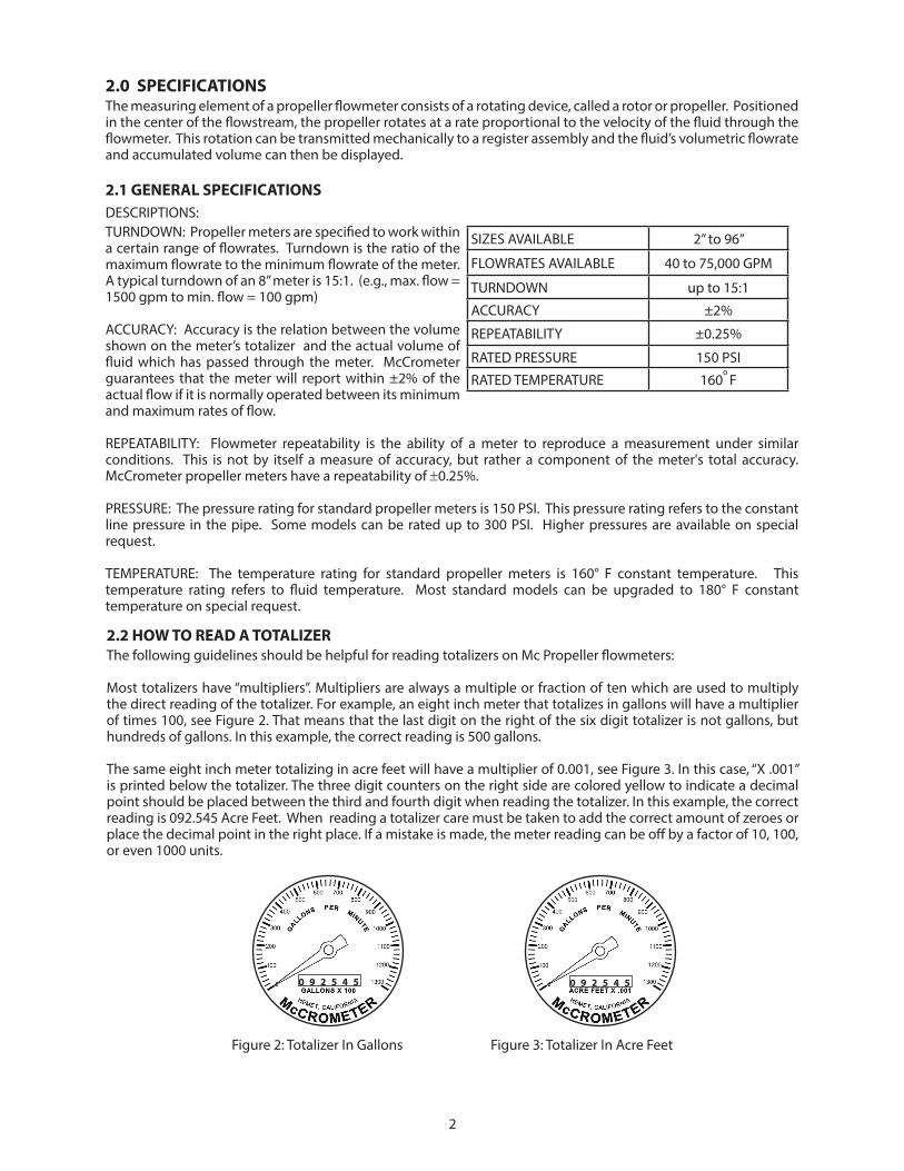
2.2 HOW TO READ A TOTALIZERThe following guidelines should be helpful for reading totalizers on Mc Propeller flowmeters:
Most totalizers have “multipliers”. Multipliers are always a multiple or fraction of ten which are used to multiply the direct reading of the totalizer. For example, an eight inch meter that totalizes in gallons will have a multiplier of times 100, see Figure 2. That means that the last digit on the right of the six digit totalizer is not gallons, but hundreds of gallons. In this example, the correct reading is 500 gallons.
The same eight inch meter totalizing in acre feet will have a multiplier of 0.001, see Figure 3. In this case, “X .001” is printed below the totalizer. The three digit counters on the right side are colored yellow to indicate a decimal point should be placed between the third and fourth digit when reading the totalizer. In this example, the correct reading is 092.545 Acre Feet. When reading a totalizer care must be taken to add the correct amount of zeroes or place the decimal point in the right place. If a mistake is made, the meter reading can be off by a factor of 10, 100, or even 1000 units.
Figure 2: Totalizer In Gallons Figure 3: Totalizer In Acre Feet
0 9 2 5 4 50 9 2 5 4 5
3
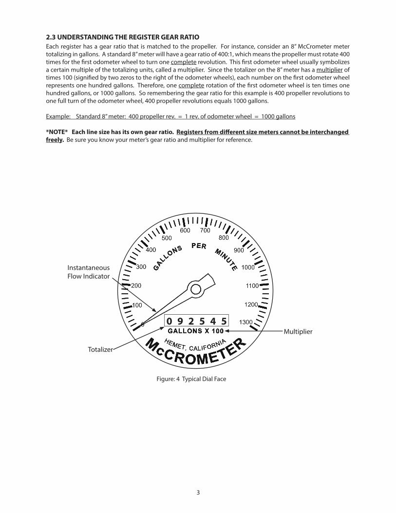
2.3 UNDERSTANDING THE REGISTER GEAR RATIOEach register has a gear ratio that is matched to the propeller. For instance, consider an 8” McCrometer meter totalizing in gallons. A standard 8” meter will have a gear ratio of 400:1, which means the propeller must rotate 400 times for the first odometer wheel to turn one complete revolution. This first odometer wheel usually symbolizes a certain multiple of the totalizing units, called a multiplier. Since the totalizer on the 8” meter has a multiplier of times 100 (signified by two zeros to the right of the odometer wheels), each number on the first odometer wheel represents one hundred gallons. Therefore, one complete rotation of the first odometer wheel is ten times one hundred gallons, or 1000 gallons. So remembering the gear ratio for this example is 400 propeller revolutions to one full turn of the odometer wheel, 400 propeller revolutions equals 1000 gallons.
Example: Standard 8” meter: 400 propeller rev. = 1 rev. of odometer wheel = 1000 gallons
*NOTE* Each line size has its own gear ratio. Registers from different size meters cannot be interchanged freely. Be sure you know your meter’s gear ratio and multiplier for reference.
Figure: 4 Typical Dial Face
Instantaneous Flow Indicator
Multiplier
Totalizer
0 9 2 5 4 5
4
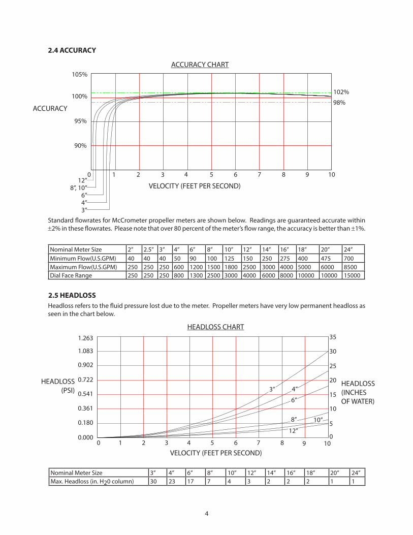
2.4 ACCURACY
Standard flowrates for McCrometer propeller meters are shown below. Readings are guaranteed accurate within ±2% in these flowrates. Please note that over 80 percent of the meter’s flow range, the accuracy is better than ±1%.
Nominal Meter Size 2” 2.5” 3” 4” 6” 8” 10” 12” 14” 16” 18” 20” 24”Minimum Flow(U.S.GPM) 40 40 40 50 90 100 125 150 250 275 400 475 700Maximum Flow(U.S.GPM) 250 250 250 600 1200 1500 1800 2500 3000 4000 5000 6000 8500Dial Face Range 250 250 250 800 1300 2500 3000 4000 6000 8000 10000 10000 15000
2.5 HEADLOSSHeadloss refers to the fluid pressure lost due to the meter. Propeller meters have very low permanent headloss as seen in the chart below.
Nominal Meter Size 3” 4” 6” 8” 10” 12” 14” 16” 18” 20” 24”Max. Headloss (in. H20 column) 30 23 17 7 4 3 2 2 2 1 1
1
HEADLOSS CHART
HEADLOSS(PSI)
VELOCITY (FEET PER SECOND)
HEADLOSS(INCHES OF WATER)
1.263
1.083
0.902
0.722
0.541
0.361
0.180
0.0000 2 3 4 5 6 7 8 9 10
0
5
10
15
20
25
30
35
ACCURACY CHART
VELOCITY (FEET PER SECOND)
ACCURACY
105%
100%
95%
90%
12”8”, 10”
6”4”3”
0 2 3 4 5 6 7 8 9 10
102%
98%
1
4”3”
6”
12”
10”8”
5
3.0 INSTALLATION INSTRUCTIONSProper meter installation is the first step to ensure excellent meter performance. Follow these instructions closely. Consult an authorized service representative or the factory for any circumstances encountered which are not covered in this manual.
All McCrometer products are tested and inspected during manufacture and prior to shipping. An inspection should be performed at the time of unpacking to detect any damage that might have occurred during shipment.
3.1 SAFETY• Any person installing, inspecting, or maintaining a McCrometer flowmeter should have a working
understanding of piping configurations and systems under pressure.• Before adjusting or removing any meter, be certain the system has depressurized completely.
• Be careful when lifting meters. Meters can cause serious injury if lifted incorrectly or dropped.• Only necessary and appropriate tools should be used when working on a meter. For tools list see page 11.• Before starting a system, make sure all connections are properly secured. Keep a safe and prudent distance
away from the meter during system start-up.
NEVER ATTEMPT TO REMOVE A METER WHILE THE LINE IS UNDER PRESSURE!!
Figure: 8 FS100 Flow Straightener
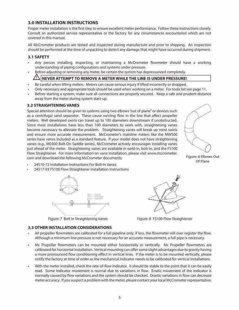
3.2 STRAIGHTENING VANESSpecial attention should be given to systems using two elbows “out of plane” or devices such as a centrifugal sand separator. These cause swirling flow in the line that affect propeller meters. Well developed swirls can travel up to 100 diameters downstream if unobstructed. Since most installations have less than 100 diameters to work with, straightening vanes become necessary to alleviate the problem. Straightening vanes will break up most swirls and ensure more accurate measurement. McCrometer’s mainline meters like the MW500 series have vanes included as a standard feature. If your model does not have straightening vanes (e.g., M0300 Bolt-On Saddle series), McCrometer actively encourages installing vanes just ahead of the meter. Straightening vanes are available in weld-in, bolt-in, and the FS100 Flow Straightener. For more information on vane installation, please visit www.mccrometer.com and download the following McCrometer documents:
• 24510-72 Installation Instructions For Bolt-In Vanes• 24517-03 FS100 Flow Straightener Installation Instructions
Figure: 6 Elbows Out Of Plane
3.3 OTHER INSTALLATION CONSIDERATIONS• All propeller flowmeters are calibrated for a full pipeline only; if less, the flowmeter will over register the flow.
Although a minimum line pressure is not necessary for an accurate measurement, a full pipe is necessary.
• Mc Propeller flowmeters can be mounted either horizontally or vertically. Mc Propeller flowmeters are calibrated for horizontal installation. Vertical mounting can offer some slight advantages due to gravity having a more pronounced flow conditioning effect in vertical lines. If the meter is to be mounted vertically, please notify the factory at time of order as the mechanical indicator needs to be calibrated for vertical installations.
• With the meter installed, check the rate-of-flow indicator. It should be stable to the point that it can be easily read. Some indicator movement is normal due to variations in flow. Erratic movement of the indicator is normally caused by flow variations and the system should be checked. Drastic variations in flow can decrease meter accuracy. If you suspect a problem with the meter, please contact your local McCrometer representative.
Figure: 7 Bolt In Straightening Vanes

6
Elbow shown - Other piping components can be pumps, valves and expansions or reductions
A
B
M0308 shown as typical saddle flow meter
Flow
3.4 PIPE RUN REQUIREMENTSFlowmeters are velocity sensing devices and are vulnerable to certain upstream disturbances. Because of this, meters need certain lengths of straight pipe runs before and after the meter. These distances usually relate to the diameter of the pipe used. Obstructions can include elbows, valves, pumps, and changes in pipe diameter. The uneven flow created by these obstructions can vary with each system. If your application provides for more than five diameters of upstream run, use the available distance.
• Upstream Requirement: Mc Propeller meters should be installed a minimum of five to ten diameters upstream of any obstructions. See the tables below. The exact upstream piping requirements are specific to the meter model number.
• Downstream Requirement: The downstream run should be one to two diameters of straight pipe length after the meter.
For upstream and downstream piping requirements relating to your specific meter, contact your local McCrometer representative. (Please be prepared to provide the serial number of your meter.)
Figure: 5 Pipe Run Requirements For Saddle And Tube Style Flow Meters
Meter Configuration A B
MW500
MZ500
MW800
MG900
WithoutFlow Straightener
5 1
With FS100Flow Straightener
1.5 1
Meter Configuration A B
M0300
MF100
MT100
WithoutStraightening vanes
10 1
WithStraightening vanes
5 1
With FS100Flow Straightener
1.5 1
FLOW
B
A
MW508 SHOWN AS
STRAIGHT NOMINAL LIN
E
TYPICAL FLOWMETER
ELBOW SHOWNOTHER PIPING COMPONENTS CAN BE PUMPS,VALVES AND EXPANSIONS OR REDUCTIONS
-
UNLESS OTHERWISE SPECIFIED
SCALE:
SIZE DWG. NO.
AREV.
MATERIAL
FINISH-
125 RMS
DO NOT SCALE DRAWING
NAME DATE
DRAWN BY
APPRV. BY
CHECKED BY
-
SHEET 1 OF 1WEIGHT:
TITLE
MW508RUN REQUIREMENT
-
MW508_InstalledFILE NAME
0:
IS PROHIBITED.
PROPRIETARY AND CONFIDENTIAL
Drawing#
NUS 6-4-2008DIMENSIONS ARE IN INCHES
0.00:
ANGULAR:
0.0000:
FRACTIONAL:
0.0:
COMMENTS:
REVISED BY
THE INFORMATION CONTAINED IN THIS
-
DRAWING IS THE SOLE PROPERTY OF
-
MCCROMETER, INC.
-ANY REPRODUCTION IN PART OR AS A
-
WHOLE WITHOUT THE WRITTEN
-
PERMISSION OF MCCROMETER, INC.
-
TOLERANCES
--
0.000:0.001
--1/640 30'0.0310.0150.0100.005
-
Measure 14” from center of Ell to determine average location of the propeller tip
Flow
MW508 shown as typical tube flow meter
A
B
7
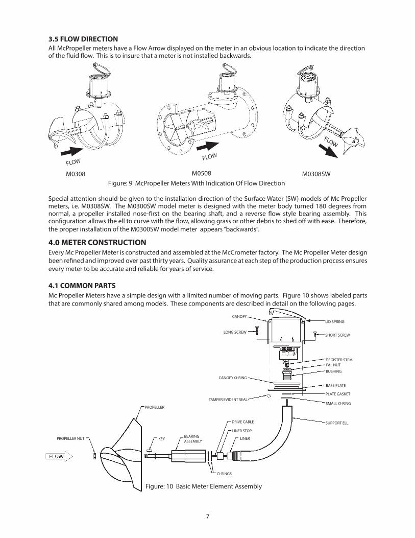
Special attention should be given to the installation direction of the Surface Water (SW) models of Mc Propeller meters, i.e. M0308SW. The M0300SW model meter is designed with the meter body turned 180 degrees from normal, a propeller installed nose-first on the bearing shaft, and a reverse flow style bearing assembly. This configuration allows the ell to curve with the flow, allowing grass or other debris to shed off with ease. Therefore, the proper installation of the M0300SW model meter appears “backwards”.
FLOW
Figure: 9 McPropeller Meters With Indication Of Flow Direction
3.5 FLOW DIRECTIONAll McPropeller meters have a Flow Arrow displayed on the meter in an obvious location to indicate the direction of the fluid flow. This is to insure that a meter is not installed backwards.
FLOW FLOW
M0308 M0508 M0308SW
4.0 METER CONSTRUCTIONEvery Mc Propeller Meter is constructed and assembled at the McCrometer factory. The Mc Propeller Meter design been refined and improved over past thirty years. Quality assurance at each step of the production process ensures every meter to be accurate and reliable for years of service.
4.1 COMMON PARTSMc Propeller Meters have a simple design with a limited number of moving parts. Figure 10 shows labeled parts that are commonly shared among models. These components are described in detail on the following pages.
Figure: 10 Basic Meter Element Assembly
CANOPY
LONG SCREW
CANOPY O-RING
TAMPER EVIDENT SEAL
PROPELLER NUT
PROPELLER
KEY BEARING ASSEMBLY
O-RINGS
DRIVE CABLE
LINER
LINER STOP
SUPPORT ELL
SMALL O-RING
PLATE GASKET
BASE PLATE
BUSHING
PAL NUTREGISTER STEM
SHORT SCREW
LID SPRING
8
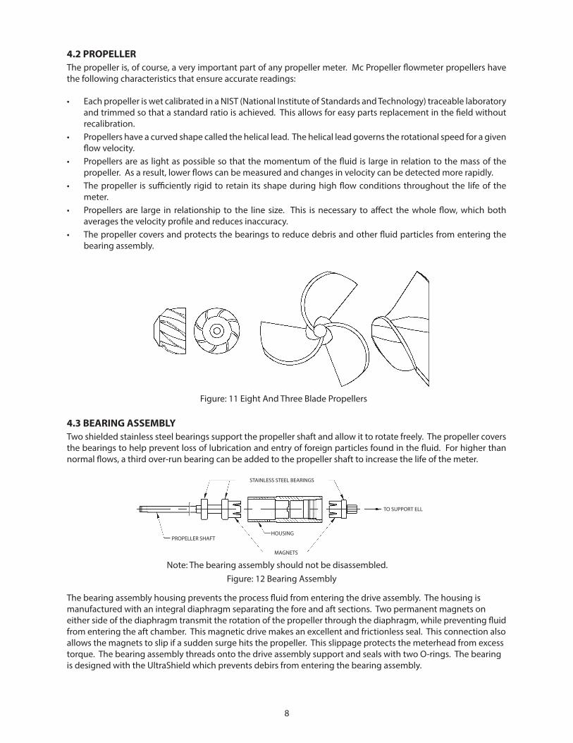
4.2 PROPELLERThe propeller is, of course, a very important part of any propeller meter. Mc Propeller flowmeter propellers have the following characteristics that ensure accurate readings:
• Each propeller is wet calibrated in a NIST (National Institute of Standards and Technology) traceable laboratory and trimmed so that a standard ratio is achieved. This allows for easy parts replacement in the field without recalibration.
• Propellers have a curved shape called the helical lead. The helical lead governs the rotational speed for a given flow velocity.
• Propellers are as light as possible so that the momentum of the fluid is large in relation to the mass of the propeller. As a result, lower flows can be measured and changes in velocity can be detected more rapidly.
• The propeller is sufficiently rigid to retain its shape during high flow conditions throughout the life of the meter.
• Propellers are large in relationship to the line size. This is necessary to affect the whole flow, which both averages the velocity profile and reduces inaccuracy.
• The propeller covers and protects the bearings to reduce debris and other fluid particles from entering the bearing assembly.
Figure: 11 Eight And Three Blade Propellers
4.3 BEARING ASSEMBLYTwo shielded stainless steel bearings support the propeller shaft and allow it to rotate freely. The propeller covers the bearings to help prevent loss of lubrication and entry of foreign particles found in the fluid. For higher than normal flows, a third over-run bearing can be added to the propeller shaft to increase the life of the meter.
Figure: 12 Bearing AssemblyNote: The bearing assembly should not be disassembled.
STAINLESS STEEL BEARINGS
HOUSING
MAGNETS
PROPELLER SHAFT
TO SUPPORT ELL
The bearing assembly housing prevents the process fluid from entering the drive assembly. The housing is manufactured with an integral diaphragm separating the fore and aft sections. Two permanent magnets on either side of the diaphragm transmit the rotation of the propeller through the diaphragm, while preventing fluid from entering the aft chamber. This magnetic drive makes an excellent and frictionless seal. This connection also allows the magnets to slip if a sudden surge hits the propeller. This slippage protects the meterhead from excess torque. The bearing assembly threads onto the drive assembly support and seals with two O-rings. The bearing is designed with the UltraShield which prevents debirs from entering the bearing assembly.
9
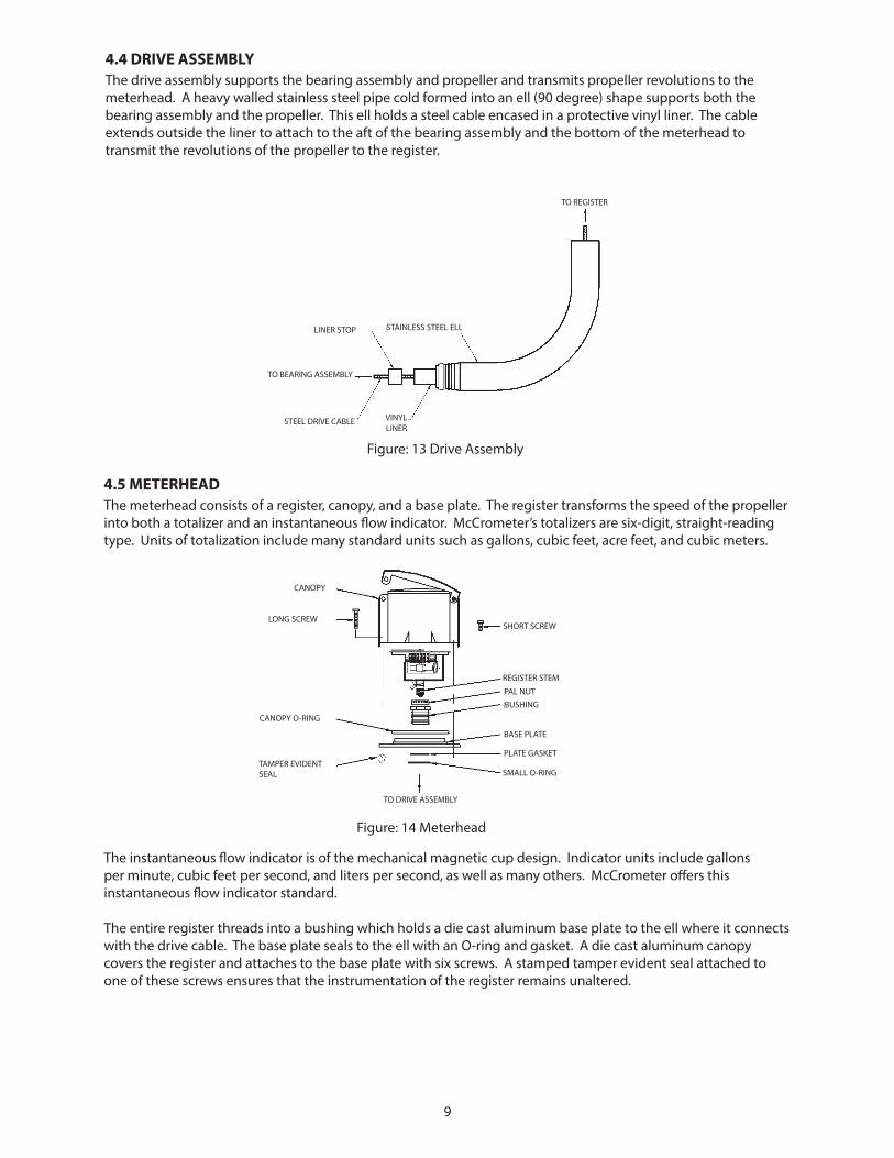
4.4 DRIVE ASSEMBLYThe drive assembly supports the bearing assembly and propeller and transmits propeller revolutions to the meterhead. A heavy walled stainless steel pipe cold formed into an ell (90 degree) shape supports both the bearing assembly and the propeller. This ell holds a steel cable encased in a protective vinyl liner. The cable extends outside the liner to attach to the aft of the bearing assembly and the bottom of the meterhead to transmit the revolutions of the propeller to the register.
TO REGISTER
TO BEARING ASSEMBLY
STEEL DRIVE CABLE VINYL LINER
STAINLESS STEEL ELLLINER STOP
Figure: 13 Drive Assembly
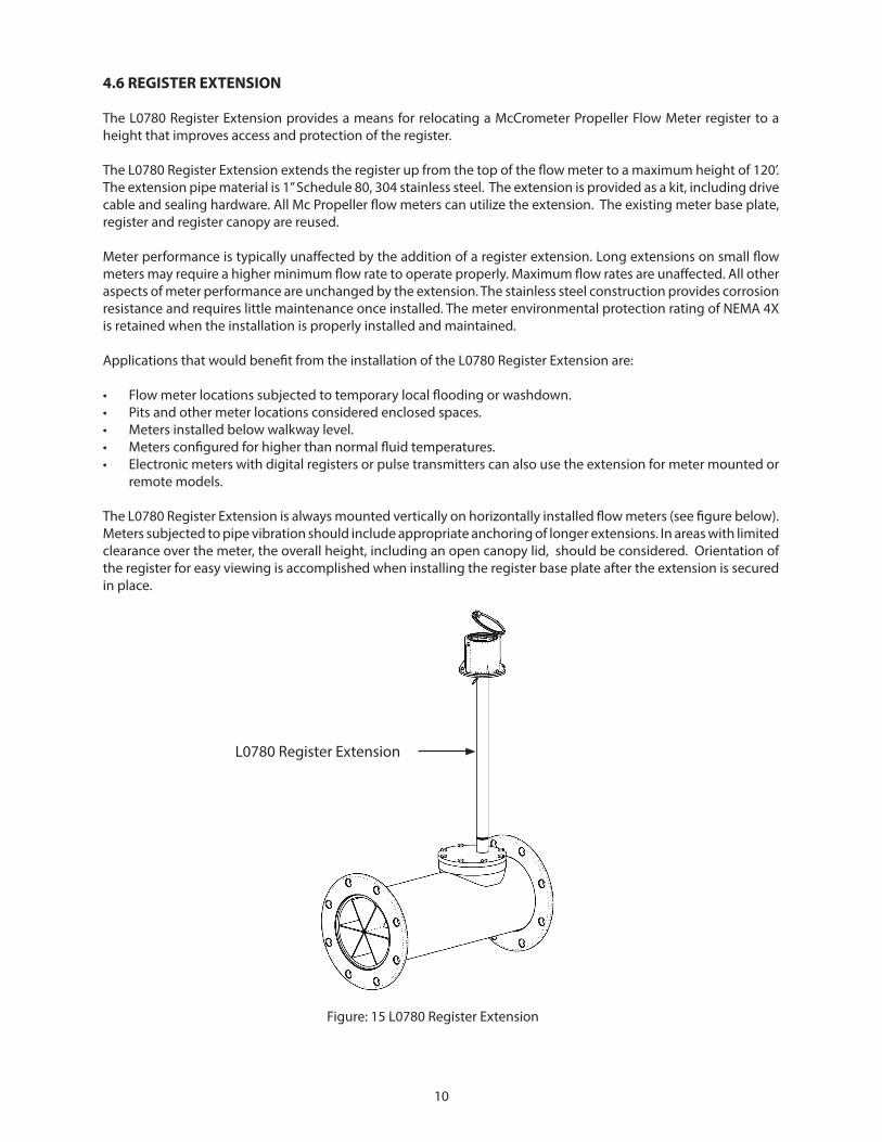
4.5 METERHEADThe meterhead consists of a register, canopy, and a base plate. The register transforms the speed of the propeller into both a totalizer and an instantaneous flow indicator. McCrometer’s totalizers are six-digit, straight-reading type. Units of totalization include many standard units such as gallons, cubic feet, acre feet, and cubic meters.
Figure: 14 Meterhead
TAMPER EVIDENT SEAL
TO DRIVE ASSEMBLY
SMALL O-RING
PLATE GASKET
BASE PLATE
BUSHINGPAL NUT
REGISTER STEM
SHORT SCREW
CANOPY O-RING
LONG SCREW
CANOPY
The instantaneous flow indicator is of the mechanical magnetic cup design. Indicator units include gallons per minute, cubic feet per second, and liters per second, as well as many others. McCrometer offers this instantaneous flow indicator standard.
The entire register threads into a bushing which holds a die cast aluminum base plate to the ell where it connects with the drive cable. The base plate seals to the ell with an O-ring and gasket. A die cast aluminum canopy covers the register and attaches to the base plate with six screws. A stamped tamper evident seal attached to one of these screws ensures that the instrumentation of the register remains unaltered.
10
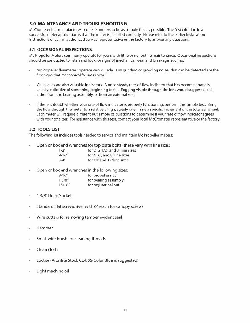
4.6 REGISTER EXTENSION
The L0780 Register Extension provides a means for relocating a McCrometer Propeller Flow Meter register to a height that improves access and protection of the register.
The L0780 Register Extension extends the register up from the top of the flow meter to a maximum height of 120’. The extension pipe material is 1” Schedule 80, 304 stainless steel. The extension is provided as a kit, including drive cable and sealing hardware. All Mc Propeller flow meters can utilize the extension. The existing meter base plate, register and register canopy are reused.
Meter performance is typically unaffected by the addition of a register extension. Long extensions on small flow meters may require a higher minimum flow rate to operate properly. Maximum flow rates are unaffected. All other aspects of meter performance are unchanged by the extension. The stainless steel construction provides corrosion resistance and requires little maintenance once installed. The meter environmental protection rating of NEMA 4X is retained when the installation is properly installed and maintained.
Applications that would benefit from the installation of the L0780 Register Extension are:
• Flow meter locations subjected to temporary local flooding or washdown.• Pits and other meter locations considered enclosed spaces.• Meters installed below walkway level.• Meters configured for higher than normal fluid temperatures.• Electronic meters with digital registers or pulse transmitters can also use the extension for meter mounted or
remote models.
The L0780 Register Extension is always mounted vertically on horizontally installed flow meters (see figure below). Meters subjected to pipe vibration should include appropriate anchoring of longer extensions. In areas with limited clearance over the meter, the overall height, including an open canopy lid, should be considered. Orientation of the register for easy viewing is accomplished when installing the register base plate after the extension is secured in place.
L0780 Register Extension
Figure: 15 L0780 Register Extension
11
5.0 MAINTENANCE AND TROUBLESHOOTINGMcCrometer Inc. manufactures propeller meters to be as trouble free as possible. The first criterion in a successful meter application is that the meter is installed correctly. Please refer to the earlier Installation Instructions or call an authorized service representative or the factory to answer any questions.
5.1 OCCASIONAL INSPECTIONSMc Propeller Meters commonly operate for years with little or no routine maintenance. Occasional inspections should be conducted to listen and look for signs of mechanical wear and breakage, such as:
• Mc Propeller flowmeters operate very quietly. Any grinding or growling noises that can be detected are the first signs that mechanical failure is near.
• Visual cues are also valuable indicators. A once steady rate-of-flow indicator that has become erratic is usually indicative of something beginning to fail. Fogging visible through the lens would suggest a leak, either from the bearing assembly, or from an external seal.
• If there is doubt whether your rate of flow indicator is properly functioning, perform this simple test. Bring the flow through the meter to a relatively high, steady rate. Time a specific increment of the totalizer wheel. Each meter will require different but simple calculations to determine if your rate of flow indicator agrees with your totalizer. For assistance with this test, contact your local McCrometer representative or the factory.
5.2 TOOLS LISTThe following list includes tools needed to service and maintain Mc Propeller meters:
• Open or box end wrenches for top plate bolts (these vary with line size): 1/2” for 2”, 2 1/2”, and 3” line sizes 9/16” for 4”, 6”, and 8” line sizes 3/4” for 10” and 12” line sizes
• Open or box end wrenches in the following sizes: 9/16” for propeller nut 1 3/8” for bearing assembly 15/16” for register pal nut
• 1 3/8” Deep Socket
• Standard, flat screwdriver with 6” reach for canopy screws
• Wire cutters for removing tamper evident seal
• Hammer
• Small wire brush for cleaning threads
• Clean cloth
• Loctite (Arontite Stock CE-805-Color Blue is suggested)
• Light machine oil
12
5.3 DISASSEMBLY AND INSPECTION PROCEDURE1. REMOVE THE METER OR ELEMENT. Depending on the model, remove the entire meter or the metering element (propeller, bearing and drive assemblies, and meterhead) to access the propeller and bearing assembly.
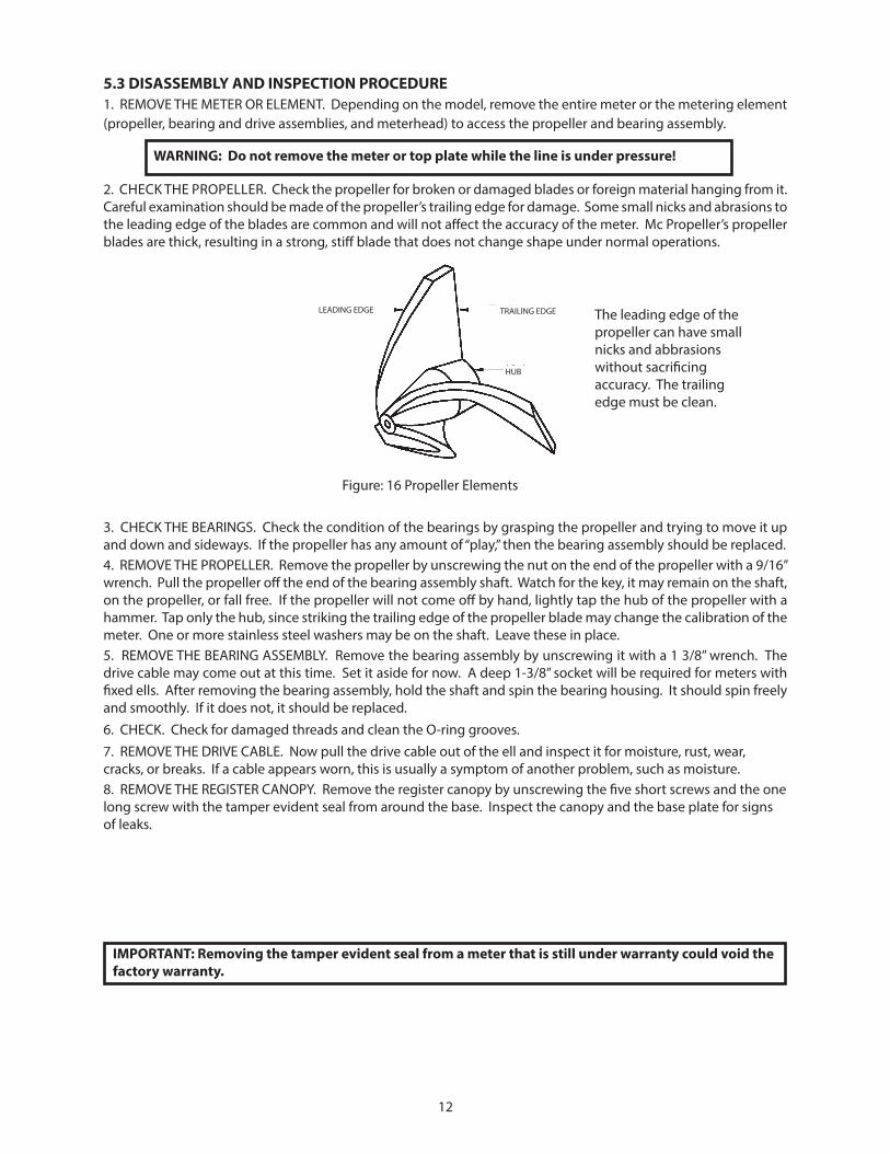
2. CHECK THE PROPELLER. Check the propeller for broken or damaged blades or foreign material hanging from it. Careful examination should be made of the propeller’s trailing edge for damage. Some small nicks and abrasions to the leading edge of the blades are common and will not affect the accuracy of the meter. Mc Propeller’s propeller blades are thick, resulting in a strong, stiff blade that does not change shape under normal operations.
3. CHECK THE BEARINGS. Check the condition of the bearings by grasping the propeller and trying to move it up and down and sideways. If the propeller has any amount of “play,” then the bearing assembly should be replaced.4. REMOVE THE PROPELLER. Remove the propeller by unscrewing the nut on the end of the propeller with a 9/16” wrench. Pull the propeller off the end of the bearing assembly shaft. Watch for the key, it may remain on the shaft, on the propeller, or fall free. If the propeller will not come off by hand, lightly tap the hub of the propeller with a hammer. Tap only the hub, since striking the trailing edge of the propeller blade may change the calibration of the meter. One or more stainless steel washers may be on the shaft. Leave these in place.5. REMOVE THE BEARING ASSEMBLY. Remove the bearing assembly by unscrewing it with a 1 3/8” wrench. The drive cable may come out at this time. Set it aside for now. A deep 1-3/8” socket will be required for meters with fixed ells. After removing the bearing assembly, hold the shaft and spin the bearing housing. It should spin freely and smoothly. If it does not, it should be replaced.6. CHECK. Check for damaged threads and clean the O-ring grooves.7. REMOVE THE DRIVE CABLE. Now pull the drive cable out of the ell and inspect it for moisture, rust, wear, cracks, or breaks. If a cable appears worn, this is usually a symptom of another problem, such as moisture.8. REMOVE THE REGISTER CANOPY. Remove the register canopy by unscrewing the five short screws and the one long screw with the tamper evident seal from around the base. Inspect the canopy and the base plate for signs of leaks.
WARNING: Do not remove the meter or top plate while the line is under pressure!
IMPORTANT: Removing the tamper evident seal from a meter that is still under warranty could void the factory warranty.
TRAILING EDGE
HUB
LEADING EDGE
Figure: 16 Propeller Elements
The leading edge of the propeller can have small nicks and abbrasions without sacrificing accuracy. The trailing edge must be clean.

13
9. REMOVE THE REGISTER HEAD. Remove the register head by loosening the pal nut on the stem of the register with a 15/16” wrench. Unscrew the whole register unit. Inspect the register for moisture. Look for a white chalky substance on the frame of the register that shows the register was wet. Turn the very bottom of the register stem several times. The register movement should turn freely. The first odometer wheel also should turn. If not, the register should be returned for repair or exchange. The purpose of the silica gel dry pack is to absorb moisture trapped during assembly. Replace the silica pack.
10. REMOVE THE CABLE LINER. If moisture exists inside the drive assembly, the liner should be taken out to dry. To remove the liner, use an item such as a large bolt to tap the liner down from the top. Tap enough to push the liner stop out from the bottom to allow the liner to be pulled free.
5.4 ORDERING REPLACEMENT PARTSWhen ordering replacement parts, the meter’s serial number is needed to ensure correct replacements. The serial number can be found on the register canopy lid. The number sequence should look similar to: 94-789-8. The first two digits are the year of manufacture, the second set of digits is the number of the meter, and the last set of digits is nominal line size. For meters manufactured before 1994, the last sets of digits are reversed. For specific meter part numbers, see the drawings of each meter type at the back of this Manual.
5.5 REASSEMBLY PROCEDUREWith the problem found and the correct replacement parts collected, the meter must be correctly reassembled to ensure trouble-free service in the future.
1. CLEAN ALL PARTS. As with any mechanical device, all of the parts that are going to be reused must be clean and free of dust and dirt. Take some time and make sure these parts are ready to be used.
2. REPLACE THE CABLE LINER. If the cable liner was removed, replace it now. Push the cable liner into the ell from the bottom up to the base plate. Replace the liner stop.
3. CLEAN THE LINER. Blow out any dirt that may be trapped inside the liner.
4. REPLACE THE BEARING ASSEMBLY. With a drop of light machine oil on your finger, lubricate the small o-rings on the end of the threaded ell. (Do not get oil on the threads of ell.) Place two drops of Loctite on the threads of the ell. Thread the bearing assembly on the ell and tighten with a wrench or a special bearing tool. Be careful not to cross thread the assembly and only snug the bearing assembly with the wrench. Extra care should be exercised in assuring that the parts are clean and the o-rings have a good sealing area.
5. REPLACE THE PROPELLER. Make sure the washers on the propeller shaft are in place. Slide the propeller over the shaft. Align the shaft and propeller keyways and insert the key. You may need to use a screw driver to push the key to the fully engaged position. Apply a small amount of Loctite to the threads of the nut and tighten to a good snug fit, but not as tight as possible.
6. REPLACE THE DRIVE CABLE. With a clean cloth, wipe off any dirt or dust from the drive cable. Apply a small amount of light machine oil to the cable and insert it all the way into the ell. To engage the cable, slowly turn the propeller as you gently push on the cable. After you are satisfied that the cable is in the bearing assembly as far as possible, check the height of the cable in relationship to the top of the mounting plate bushing. The cable should be within 1/4 of an inch (plus or minus) from the top of the bushing. If not, it is the wrong cable or the cable is not fully seated into the bearing assembly.
7. REPLACE THE REGISTER HEAD. Thread the pal nut, with the open face up, onto the stem on the bottom of the register. The nut should be at least halfway up the threads. Place the register stem on the drive cable and screw it into the mounting plate bushing. The register should be screwed down far enough that the cable is well into the register stem, but not far enough to bind the cable. Face the register the desired direction and tighten the pal nut to lock the register into position.
8. CHECK. Spin the propeller to check that the rate of flow indicator and totalizer are engaged. Listen for any clicking or grinding noises. The meter should turn quietly.
IMPORTANT: Use only two drops of Loctite. Too much Loctite can cause the aft bearing to seize.

14
9. REPLACE THE REGISTER CANOPY. Install the large o-ring and flat gasket onto the base plate. Use a small amount of light oil to lubricate the o-ring and place the register canopy down over it. Push down until the o-ring bottoms out against the base plate. Replace the six screws and lightly snug them.
10. RE-INSTALL THE FLOWMETER. Re-install the flowmeter. Before pressurizing the system, make sure all connections are properly secured. As an obvious general safety consideration, maintain a safe and prudent distance from the meter when the system is to be started. After the system restarts, the indicator should be smooth and the meter quiet.
6.0 TECHNICAL SPECIFICATIONS
TECHNICAL SUPPORTFor technical assistance, please contact your authorized service representative at:
ACCURACY/REPEATABILITY: ±2% of reading guaranteed throughout full range; ±1% over reduced range; Repeatability 0.25% or better
MAXIMUM TEMPERATURE: (Standard Construction) 160°F constant
PRESSURE RATING: 150 psi MATERIALS:
BEARING ASSEMBLY: Impeller shaft is 316 stainless steel. Ball bearings are 440C stainless steel. MAGNETS: (Permanent type) Alnico BEARING HOUSING: Brass; Stainless Steel optional SADDLE: 304 stainless steel construction
REGISTER: An instantaneous flowrate indicator and six-digit straight-reading totalizer are standard. The register is hermetically sealed within a die cast aluminum case. This protective housing includes a domed acrylic lens and hinged lens cover with locking hasp. IMPELLER: Impellers are manufactured of high-impact plastic, retaining their shape and accuracy over the life
of the meter. High temperature impeller is optional.
OPTIONS
•Saddlecanbeconstructedtofitanyoutside diameter pipe dimensions, including metric sizes •Canbeusedonavarietyofpipematerialssuch as steel, plastic, cast iron, cement or asbestos cement •Registerextension•Allstainlesssteelbearingassembly•Hightemperatureconstruction•Marathonbearingassemblyforhigherthan normal flowrates •FlowComElectronicRegister•Acompletelineofflowrecording/control instrumentation including transmitters and flow computers•Blankrepairsaddle•Vanes•Flowstraighteners•CanopyBoot•Lidspri
15
R014
7-00

16
R014
7-00
P101
05-X
X
17
R014
7-00
18
R014
7-00
19
R014
7-00
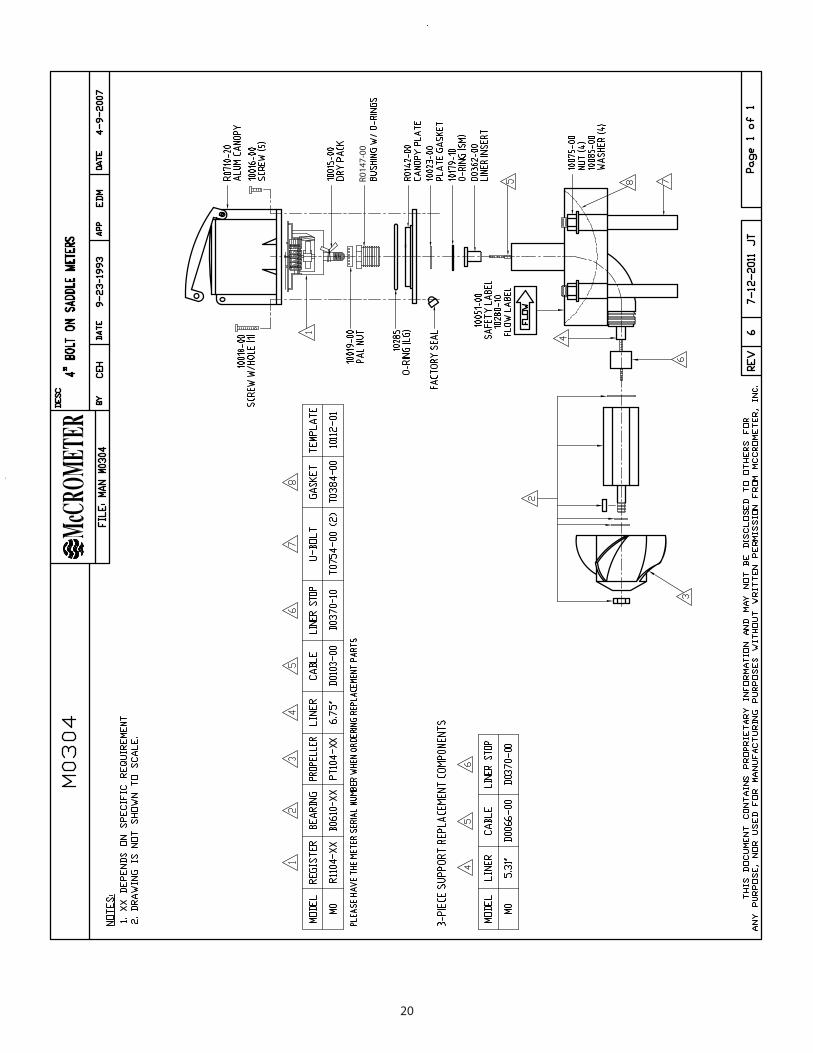
20
R014
7-00
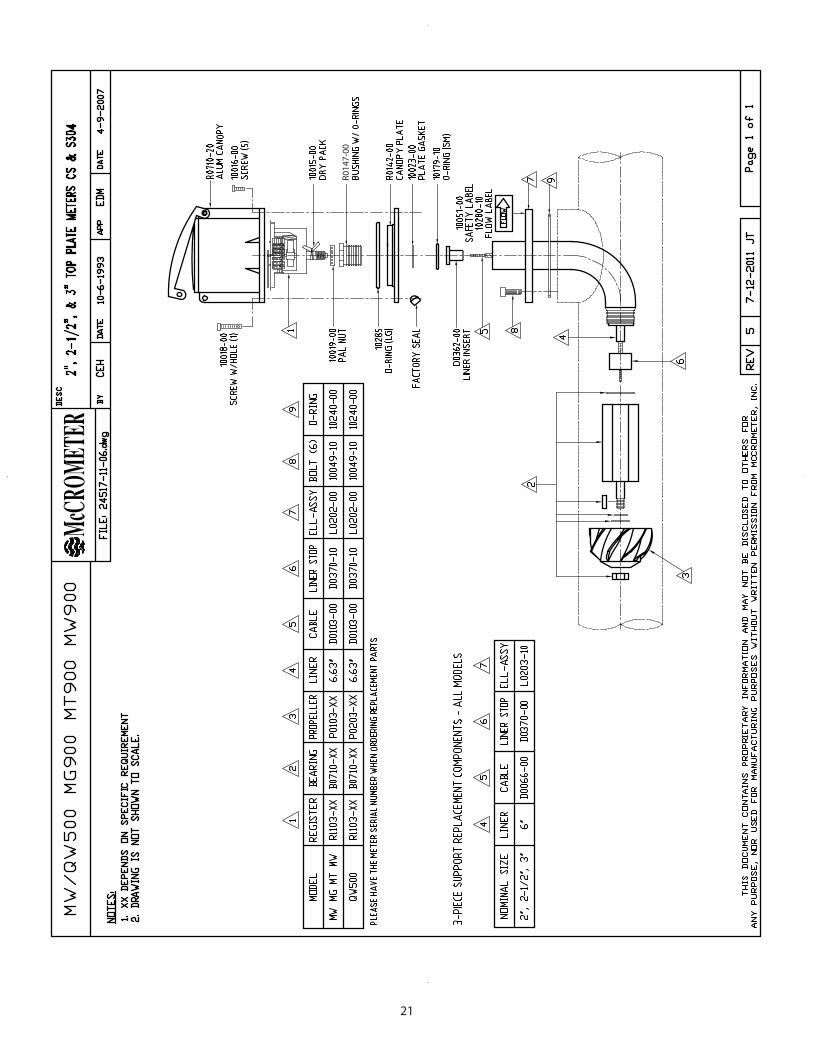
21
R014
7-00
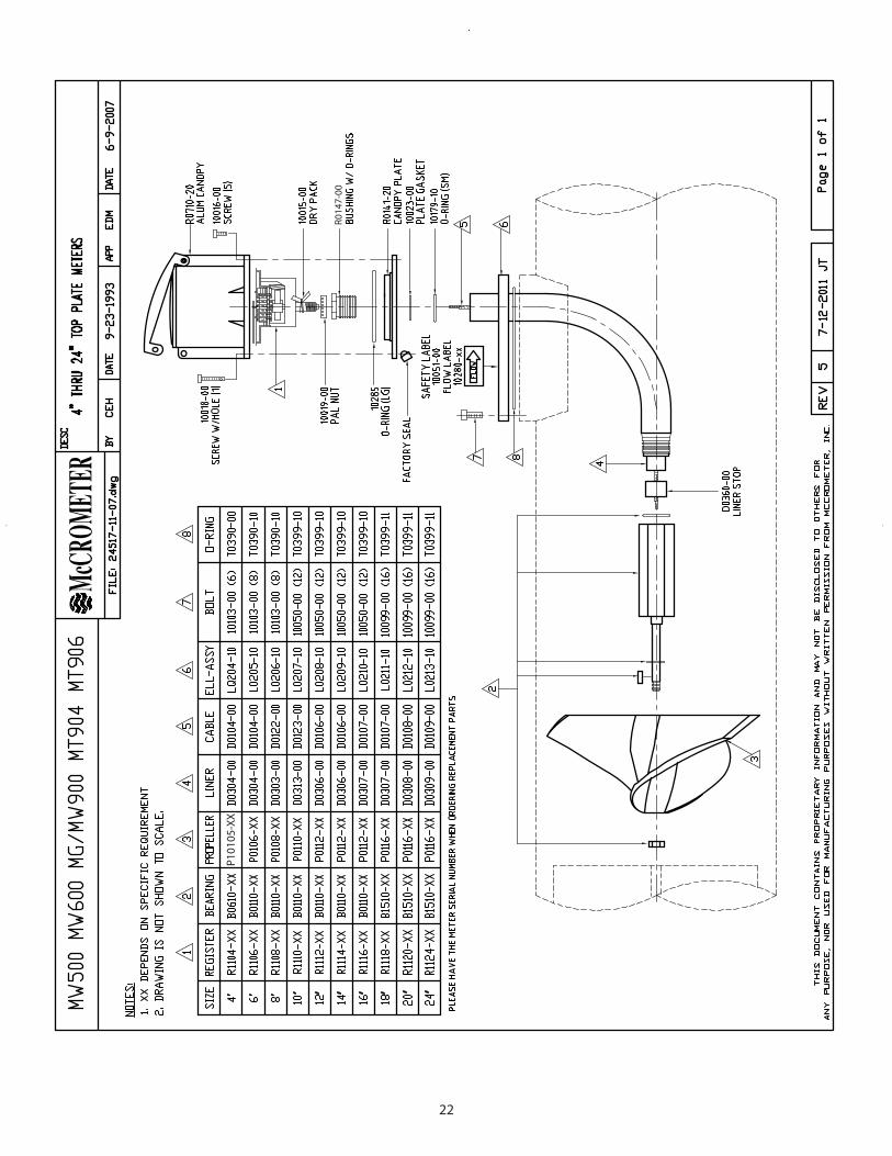
22
R014
7-00
P101
05-X
X
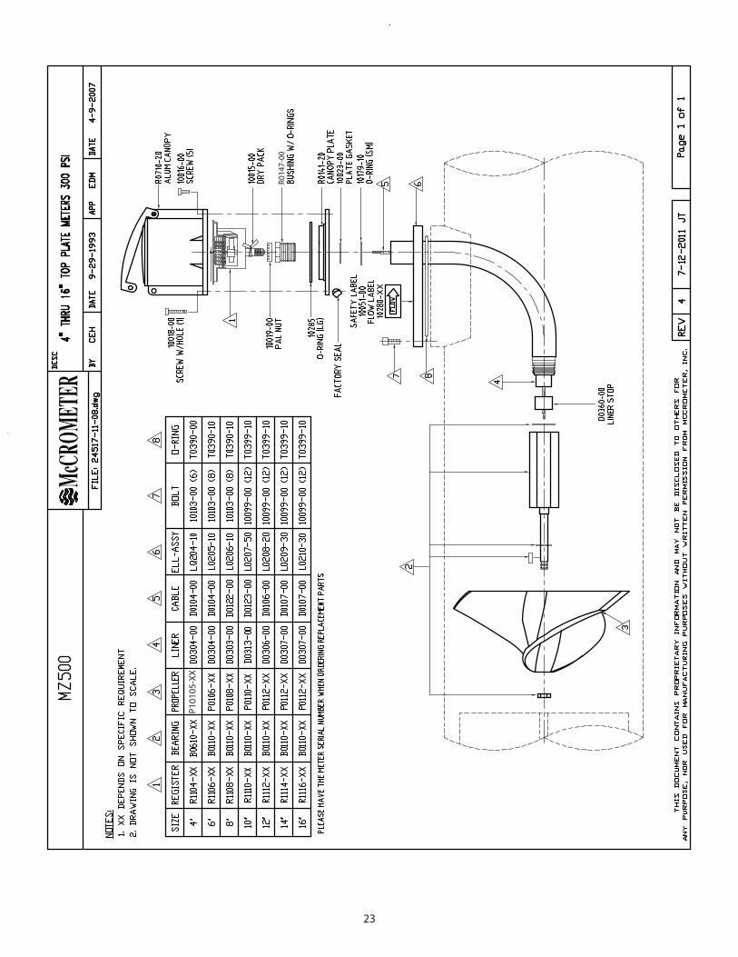
23
R014
7-00
P101
05-X
X
24
R014
7-00
25
R014
7-00
P101
05-X
X

26
R014
7-00
B150
0-XX
B150
0-XX
B150
0-XX
B150
0-XX
B150
0-XX
B150
0-XX
B150
0-XX
B150
0-XX
B150
0-XX
B150
0-XX
B150
0-XX
27
R014
7-00
1067
3/10
777
28
R014
7-00
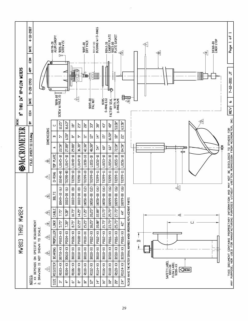
29
R014
7-00

30
WARRANTY
This Warranty shall apply to and be limited to the original purchaser consumer of any McCrometer product. Meters or instruments defective because of faulty material or workmanship will be repaired or replaced, at the option of McCrometer Inc., free of charge, FOB the factory in Hemet, California, within a period of one (1) year from the date of delivery.Repairs or modifications by others than McCrometer Inc. or their authorized representatives shall render this Warranty null and void in the event that factory examination reveals that such repair or modification was detrimental to the meter or instrument. Any deviations from the factory calibration require notification in writing to McCrometer Inc. of such recalibrations or this Warranty shall be voided.
In case of a claim under this Warranty, the claimant is instructed to contact McCrometer Inc., 3255 W. Stetson Ave., Hemet, California 92545, and to provide an identification or description of the meter or instrument, the date of delivery, and the nature of the problem.
The Warranty provided above is the only Warranty made by McCrometer Inc. with respect to its products or any parts thereof and is made expressly in lieu of any other warranties, by course of dealing, usages of trade or otherwise, expressed or implied, including but not limited to any implied warranties of fitness for any particular purpose or of merchantability under the uniform commercial code. It is agreed this Warranty is in lieu of and buyer hereby waives all other warranties, guarantees or liabilities arising by law or otherwise. Seller shall not incur any other obligations or liabilities or be liable to buyer, or any customer of buyer for any anticipated or lost profits, incidental or consequential damages, or any other losses or expenses incurred by reason of the purchase, installation, repair, use or misuse by buyer or third parties of its products (including any parts repaired or replaced); and seller does not authorize any person to assume for seller any other liability in connection with the products or parts thereof. This Warranty cannot be extended, altered or varied except by a written instrument signed by seller and buyer.
This Warranty gives you specific legal rights, and you may also have other rights which vary from state to state.
McCrometer Inc. reserves the right to make improvements and repairs on product components which are beyond the Warranty period at the manufacturer’s option and expense, without obligation to renew the expired Warranty on the components or on the entire unit. Due to the rapid advancement of meter design technology, McCrometer Inc. reserves the right to make improvements in design and material without prior notice to the trade.
All sales and all agreement in relation to sales shall be deemed made at the manufacturer’s place of business in Hemet, California and any dispute arising from any sale or agreement shall be interpreted under the laws of the State of California

OTHER McCROMETER PRODUCTS INCLUDE:
Magnetic Flowmeters
Magnetic Flowmeters
Magnetic Flowmeters
Propeller Flowmeters
Remote Telemetry System
Propeller Flowmeters
Differential Pressure Flowmeters
Differential Pressure Flowmeters
Differential Pressure Flowmeters
Copyright © 1997-2013 McCrometer, Inc. All printed material should not be changed or altered without permission of McCrometer. Any published technical data and instructions are subject to change without notice. Contact your McCrometer representative for current technical data and instructions. Mc® of Mc Propeller is a registered trademark of McCrometer, Inc.
www.mccrometer.com
Lit. #24517-11 Rev. 4.0/11-13


