287

McGRAW-HILL NETWORKING ANDTELECOMMUNICATIONS
Crash CourseShepard Telecom Convergence, 2/eShepard Telecom Crash Course, 2/eBedell Wireless Crash Course, 2/eShepard VoIP Crash Course
McGraw-Hill CommunicationsSmith/Collins 3G Wireless NetworksBates Broadband Telecom Handbook, 2/eCollins Carrier Grade Voice over IPBenner Fibre Channel for SANsBates GPRSSulkin Implementing the IP-PBXRussell Signaling System #7, 4/eKarim/Sarraf W-CDMA and cdma2000 for 3G Mobile NetworksBates Wireless Broadband HandbookRohde/Whitaker Communications Receivers, 3/eSayre Complete Wireless DesignOSA Fiber Optics HandbookBates Optimizing Voice in ATM/IP Mobile NetworksRoddy Satellite Communications, 3/eSimon Spread Spectrum Communications HandbookSnyder Wireless Telecommunications Networking with
ANSI-41, 2/e
ReferenceMuller Desktop Encyclopedia of Telecommunications, 3/eClayton McGraw-Hill Illustrated Telecom Dictionary, 3/ePecar Telecommunications Factbook, 2/eRussell Telecommunications Pocket Reference

This page intentionally left blank

WIMAX HANDBOOK

This page intentionally left blank
WiMAXHandbookBuilding 802.16
Wireless Networks
Frank Ohrtman
McGraw-HillNew York Chicago San Francisco Lisbon
London Madrid Mexico City Milan New DelhiSan Juan Seoul Singapore Sydney Toronto

Copyright © 2005 by The McGraw-Hill Companies, Inc. All rights reserved. Manufactured in the United States of America. Exceptas permitted under the United States Copyright Act of 1976, no part of this publication may be reproduced or distributed in any formor by any means, or stored in a database or retrieval system, without the prior written permission of the publisher.
0-07-158903-1
The material in this eBook also appears in the print version of this title: 0-07-145401-2.
All trademarks are trademarks of their respective owners. Rather than put a trademark symbol after every occurrence of a trademarked name, we use names in an editorial fashion only, and to the benefit of the trademark owner, with no intention ofinfringement of the trademark. Where such designations appear in this book, they have been printed with initial caps.
McGraw-Hill eBooks are available at special quantity discounts to use as premiums and sales promotions, or for use incorporatetraining programs. For more information, please contact George Hoare, Special Sales, at [email protected] or (212) 904-4069.
TERMS OF USE
This is a copyrighted work and The McGraw-Hill Companies, Inc. (“McGraw-Hill”) and its licensors reserve all rights in and to thework. Use of this work is subject to these terms. Except as permitted under the Copyright Act of 1976 and the right to store andretrieve one copy of the work, you may not decompile, disassemble, reverse engineer, reproduce, modify, create derivative worksbased upon, transmit, distribute, disseminate, sell, publish or sublicense the work or any part of it without McGraw-Hill’s prior consent. You may use the work for your own noncommercial and personal use; any other use of the work is strictly prohibited. Yourright to use the work may be terminated if you fail to comply with these terms.
THE WORK IS PROVIDED “AS IS.” McGRAW-HILL AND ITS LICENSORS MAKE NO GUARANTEES OR WARRANTIESAS TO THE ACCURACY, ADEQUACY OR COMPLETENESS OF OR RESULTS TO BE OBTAINED FROM USING THEWORK, INCLUDING ANY INFORMATION THAT CAN BE ACCESSED THROUGH THE WORK VIA HYPERLINK OR OTHERWISE, AND EXPRESSLY DISCLAIM ANY WARRANTY, EXPRESS OR IMPLIED, INCLUDING BUT NOT LIMITEDTO IMPLIED WARRANTIES OF MERCHANTABILITY OR FITNESS FOR A PARTICULAR PURPOSE. McGraw-Hill and itslicensors do not warrant or guarantee that the functions contained in the work will meet your requirements or that its operation willbe uninterrupted or error free. Neither McGraw-Hill nor its licensors shall be liable to you or anyone else for any inaccuracy, erroror omission, regardless of cause, in the work or for any damages resulting therefrom. McGraw-Hill has no responsibility for the con-tent of any information accessed through the work. Under no circumstances shall McGraw-Hill and/or its licensors be liable for anyindirect, incidental, special, punitive, consequential or similar damages that result from the use of or inability to use the work, evenif any of them has been advised of the possibility of such damages. This limitation of liability shall apply to any claim or cause what-soever whether such claim or cause arises in contract, tort or otherwise.
DOI: 10.1036/0071454012

We hope you enjoy thisMcGraw-Hill eBook! If
you’d like more information about this book,its author, or related books and websites,please click here.
Professional
Want to learn more?

This book is dedicated to my son, Konrad FranklinOhrtman, born June 2004. May all this be ancienttechnological history by the time he is old enough toread this book.

This page intentionally left blank
ABOUT THE AUTHOR
Frank Ohrtman has almost 20 years experience in VoIP andwireless applications. Mr. Ohrtman learned to perform in-depthresearch and write succinct analyses during his years as a NavyIntelligence Officer (1981–1991) where he specialized in electronicintelligence and electronic warfare. He is a veteran of U.S. Navyactions in Lebanon (awarded Navy Expeditionary Medal),Grenada, Libya (awarded Joint Service Commendation Medal) andthe Gulf War (awarded National Defense Service Medal).
His career in VoIP began with selling VoIP gateway switches forNetrix Corporation to long distance bypass carriers. He went on topromote softswitch solutions for Lucent Technologies (QwestAccount Manager) and Vsys (Western Region Sales Manager). Mr.Ohrtman is the author of Softswitch: Architecture for Voice over IP, anumber one bestseller on USTA Bookstore’s bestseller list, Wi-FiHandbook: Building 802.11b Wireless Networks, and Voice over802.11
He holds a master of science in Telecommunications from Col-orado University College of Engineering (master’s thesis:“Softswitch as Class 4 Replacement—A Disruptive Technology”), amaster of arts in International Relations from Boston Universityand a BA, Political Science from University of Iowa. Mr. Ohrtmanlives in Denver, CO where he is the president of WMX Systems, anext generation networks professional consulting and systemsintegration firm, (http://www.wmxsystems.com [email protected]) 720-839-4063.
Copyright © 2005 by The McGraw-Hill Companies, Inc. Click here for terms of use.

This page intentionally left blank

CONTENTS AT A GLANCE
1 Introduction 1
2 WiMAX: The Physical Layer (PHY) 13
3 The Medium Access Control (MAC) Layer 29
4 How WiMAX Works 41
5 Quality of Service (QoS) on WiMAX 53
6 Dealing with Interference with WiMAX 77
7 Security and 802.16 WiMAX 95
8 WiMAX VoIP 105
9 WiMAX IPTV 131
10 Regulatory Aspects of WiMAX 139
11 How to Dismantle a PSTN: The Business Case for WiMAX 163
12 Projections: WiMAX Is a Disruptive Technology 197
Appendix A: Considerations in Building Wireless Networks 205
Index 247

This page intentionally left blank
CONTENTS
Acknowledgments xxi
Preface xxiii
Chapter 1 Introduction 1
Telecommunications Networks — The Need for an Alternative Form of Access 3
Switching 4
Transport 4
Access 5
Replacing the PSTN One Component at a Time 5
Objections to Wireless Networks 6
QoS 6
Security 6
Interference Mitigation 6
Economic Advantage of WiMAX 7
Regulatory Aspects of Wireless Networks 8
Improved Quality of Life with Wireless Networks 8
Disruptive Technology 9
Disruption for Telephone Companies 10
Disruption for Cable TV and Satellite TV Companies 10
Disruption for Cell Phone Companies 10
Disruption for the Backhaul Industry 10
Conclusion 11
For more information about this title, click here

Contentsxiv
Chapter 2 WiMAX: The Physical Layer (PHY) 13
Introduction 14
The Function of the PHY 15
OFDM: The “Big So What?!” of WiMAX 16
TDD and FDD 17
Adaptive Antenna System (AAS) 18
WiMAX Variants 18
OFDM Variants 2–11 GHz 19
Single Carrier (SC) Variants 22
Conclusion 27
Chapter 3 The Medium Access Control (MAC) Layer 29
The MAC as the “Smarts” for the Physical Layer 30
The MAC and WiMAX Architecture 30
Service Classes and QoS 32
Service-Specific Convergence Sublayers 34
Common Part Sublayer 35
Packing and Fragmentation 37
PDU Creation and Automatic Repeat Request (ARQ) 37
Transmission Convergence (TC) Layer 39
Chapter 4 How WiMAX Works 41
Channel Acquisition 42
Initial Ranging and Negotiation of SS Capabilities 42
SS Authentication and Registration 44
IP Connectivity 44
Connection Setup 45
Contents xv
Radio Link Control (RLC) 46
The UL 48
Service Flow 49
Conclusion 51
Chapter 5 Quality of Service (QoS) on WiMAX 53
Overview 54
The Challenge 54
Legacy QoS Mechanisms 55
FDD/TDD/OFDM 55
Forward Error Correction (FEC) 56
Bandwidth Is the Answer — What Was the Question? 57
QPSK Versus QAM 63
Multiplexing in OFDM 64
What OFDM Means to WiMAX 66
QoS: Error Correction and Interleaving 66
QoS Measures Specific to the WiMAX Specification 67
Theory of Operation 67
Service Flows 68
The Object Model 70
Service Classes 71
Authorization 71
Types of Service Flows 72
Service Flow Management 74
Conclusion 75
Contents
Contentsxvi
Chapter 6 Dealing with Interference with WiMAX 77
Interference — Some Assumptions 78
Defining Interference or “Think Receiver” 78
Forms of Interference 79
Countering Interference 82
Changing Channels Within the ISM or U-NII Bands 83
Dealing with Distance 84
Internal (CoCH) Sources of Interference 85
OFDM in Overcoming Interference 86
Handling ISI 88
Mitigating Interference with Antenna Technology 89
Multiple Antennas: AAS 89
Adaptive Antenna (AA) Techniques 91
Dynamic Frequency Selection (DFS) 93
If You Want Interference, Call the Black Ravens 93
Chapter 7 Security and 802.16 WiMAX 95
Security in WiMAX Networks 96
The Security Sublayer 96
The PKM Protocol 100
TEK Exchange Overview 102
Cryptographic Methods 102
Conclusion 104
Chapter 8 WiMAX VoIP 105
PSTN Architecture 106
Contents xvii
Voice Over WiMAX—The Challenge 107
VoIP 107
Origins of VoIP 107
How Does VoIP Work? 108
VoIP Signaling Protocols 109
Switching 113
Softswitch (aka Gatekeeper, Media Gateway Controller) 113
Other Softswitch Components 115
VoIP and Softswitch Pave the Way for Voice Over WiMAX 117
Objections to VoIP Over WiMAX 117
Objection One: Voice Quality of WiMAX VoIP 118
Solution: Voice Codecs Designed for VoIP, Especially VoIP Over WiMAX 122
Modifying Voice Codecs to Improve Voice Quality 122
The QoS Solution: Fix Circuit-Switched Voice Codecs in a Packet Switched, Wireless World with Enhanced Speech-Processing Software 123
Objection Two: Security for WiMAX VoIP 124
Objection Three: CALEA and E911 125
E911 125
Architecture of WiMAX VoIP: Putting It All Together 126
WiMAX VoIP Phones 127
Conclusion 128
Chapter 9 WiMAX IPTV 131
WISP WiMAX Triple Play? 132
IPTV: Competing with Cable TV and Satellite TV 132
How It Works 134
Bandwidth and Compression Technologies 136
Other Video Revenue Streams 136
Video on Demand 137
Personal Video Recorder 138
Conclusion: A TV Station Called WiMAX 138
Chapter 10 Regulatory Aspects of WiMAX 139
Operate Licensed or Unlicensed? 140
Current Regulatory Environment 142
Power Limits 142
WiMAX 802.16 — Its Relationship to FCC Part 15, Section 247 143
802.16 — FCC Part 15, Section 407 143
Interference 144
Laws on Antennas and Towers 150
New Unlicensed Frequencies 151
Unlicensed Frequencies Summary 152
The FCC New Spectrum Policy 152
Four Problem Areas in Spectrum Management and Their Solutions 153
Recent Statements from the FCC on Broadband and Spectrum Policy 159
Conclusion 161
Chapter 11 How to Dismantle a PSTN: The Business Case for WiMAX 163
Overview 164
Immediate Markets 164
Contentsxviii
Secondary Markets 166
Demographics 167
Services 168
Frequency Band Alternatives 170
Capital Expense (CAPEX) Items 172
CPE Equipment 174
Operating Expense (OPEX) Items 176
The Business Case 176
Future Markets 179
Economics of Wireless in the Enterprise 182
You Can “Take It with You When You Go” 182
Economics of WiMAX in Public Networks 184
Economic Benefits of Ubiquitous Broadband 186
Conclusion 195
Chapter 12 Projections: WiMAX Is a Disruptive Technology 197
Disruptive Technology 198
How WiMAX Will Disrupt the Telephone Industry 199
Cheaper 199
Simpler 200
Smaller 200
More Convenient to Use 200
Deconstruction 201
Goetterdammerung or Creative Destruction in the Telecommunications Industry 201
Contents xix

Appendix A Considerations in Building Wireless Networks 205
Design 206
Network Topology 206
Link Type 207
Environment 207
Throughput, Range, and Bit Error Rate (BER) 208
Multipath Fading Tolerance 209
Link Budget 209
Frequency Band 209
Wireless Protocols Preceding WiMAX 215
802.11 Summary 217
Planning 217
Fresnel Zone 218
How to Calculate a Link Budget 220
Site Survey 227
How to Make a Frequency Plan 228
Frequency Allocation 230
Equipment Selection 231
How to Look at Specs 231
The WAN/MAN Connection 232
How to Put a BS Where There Is No Power 244
How to Overcome Line-of-Sight Limitations 246
Index 247
Contentsxx
ACKNOWLEDGMENTSLike any book, this project would not have been possible without thegenerous assitance of a number of dedicated professionals. I wouldespecially like to recognize Herm Braun, professional engineer,“Wireless Emeritus” at Denver University, for providing a sanitycheck on the technical chapters. Roger Marks of the IEEE 802.16Working Group for steering my research in the right direction whilewaiting for the final specification to be published. Also in the Work-ing Group, a big thanks to Dean Chang, Carl Eklund, Kenneth L.Stanwood, and Stanley Wang. To the Intel team, a big thanks toGovindan Nair, Joey Chou, Tomaz Madejski, Krzysztof Perycz,David Putzolu, and Jerry Sydir. I also want to extend a specialthanks to the WiMAX Forum for their help in the economics chap-ter. Tim Stewart of NetUnwired was especially helpful in guidingme to understand the “real products” aimed at “the real market.” Iwould also like to thank Dan Lubar for his technical support alongthe way as well as Charlie Loverso and Kevin Suitor of RedlineCommunications.
Copyright © 2005 by The McGraw-Hill Companies, Inc. Click here for terms of use.

This page intentionally left blank

PREFACEI wrote my first book, Softswitch: Architecture for VoIP, partially as atreatise on how the telecommunications industry could bypass theincumbent telephone company’s central office (CO). That still left“the last mile.” I then wrote (with Konrad Roeder as coauthor) Wi-FiHandbook: Building 802.11b Wireless Networks, with an eye to IEEE802.11b (aka Wi-Fi) as a last-mile wireless, unlicensed bypass of thetelco’s copper wires. To underline that assertion, I went on to authorVoice over 802.11.
However, 802.11 technologies lacked the throughput, power, andrange to be considered “carrier class” replacements for the copperwire last mile. When I started to study WiMAX (IEEE 802.16), Ibegan to see that it was the final piece that would allow a completebypass of the telco’s public switched telephone network (PSTN). Iwould not rest until I compiled and published this book. Therefore,this book is a very short treatise on how the PSTN can be bypassedin its entirety.
Some state that WiMAX is overhyped. I disagree. It is built onlegacy technologies conforming with Data-Over-Cable Service Inter-face Specification (DOCSIS). It should be noted that even though thespecification was approved only 4 months prior to the time of thiswriting (Fall 2004) and that true 802.16-spec chips will not be avail-able until mid-2005, there have been a number of WiMAX-like or“pre-WiMAX” products on the market (built by vendors participatingin the various 802.16 working groups) that perform close to the para-meters of the specification. This should be verification enough of theperformance of WiMAX.
Copyright © 2005 by The McGraw-Hill Companies, Inc. Click here for terms of use.

This page intentionally left blank

Introduction
CHAPTER 11
Copyright © 2005 by The McGraw-Hill Companies, Inc. Click here for terms of use.
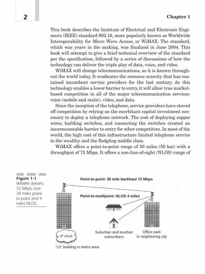
This book describes the Institute of Electrical and Electronic Engi-neers (IEEE) standard 802.16, more popularly known as WorldwideInteroperability for Micro Wave Access, or WiMAX. The standard,which was years in the making, was finalized in June 2004. Thisbook will attempt to give a brief technical overview of the standardper the specification, followed by a series of discussions of how thetechnology can deliver the triple play of data, voice, and video.
WiMAX will change telecommunications, as it is known through-out the world today. It eradicates the resource scarcity that has sus-tained incumbent service providers for the last century. As thistechnology enables a lower barrier to entry, it will allow true market-based competition in all of the major telecommunication services:voice (mobile and static), video, and data.
Since the inception of the telephone, service providers have stavedoff competition by relying on the exorbitant capital investment nec-essary to deploy a telephone network. The cost of deploying copperwires, building switches, and connecting the switches created aninsurmountable barrier to entry for other competitors. In most of theworld, the high cost of this infrastructure limited telephone serviceto the wealthy and the fledgling middle class.
WiMAX offers a point-to-point range of 30 miles (50 km) with athroughput of 72 Mbps. It offers a non-line-of-sight (NLOS) range of
Chapter 12
Point-to-point: 30 mile backhaul 72 Mbps
Point-to-multipoint: NLOS 4 miles
Suburban and exurbansubscribers
Office parkin neighboring city
"Lit" building in metro area
IP cloud
Figure 1-1WiMAX delivers72 Mbps over30 miles point-to-point and 4miles NLOS.
4 miles and, in a point-to-multipoint distribution, the model can dis-tribute nearly any bandwidth to almost any number of subscribers,depending on subscriber density and network architecture. Figure1-1 illustrates these exciting capabilities.
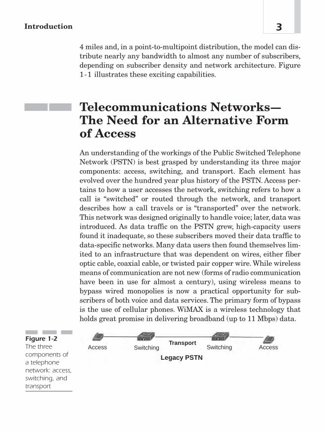
Telecommunications Networks—The Need for an Alternative Formof AccessAn understanding of the workings of the Public Switched TelephoneNetwork (PSTN) is best grasped by understanding its three majorcomponents: access, switching, and transport. Each element hasevolved over the hundred year plus history of the PSTN. Access per-tains to how a user accesses the network, switching refers to how acall is “switched” or routed through the network, and transportdescribes how a call travels or is “transported” over the network.This network was designed originally to handle voice; later, data wasintroduced. As data traffic on the PSTN grew, high-capacity usersfound it inadequate, so these subscribers moved their data traffic todata-specific networks. Many data users then found themselves lim-ited to an infrastructure that was dependent on wires, either fiberoptic cable, coaxial cable, or twisted pair copper wire. While wirelessmeans of communication are not new (forms of radio communicationhave been in use for almost a century), using wireless means tobypass wired monopolies is now a practical opportunity for sub-scribers of both voice and data services. The primary form of bypassis the use of cellular phones. WiMAX is a wireless technology thatholds great promise in delivering broadband (up to 11 Mbps) data.
3Introduction
Legacy PSTN
Access AccessSwitching SwitchingTransport
Figure 1-2The threecomponents ofa telephonenetwork: access,switching, andtransport

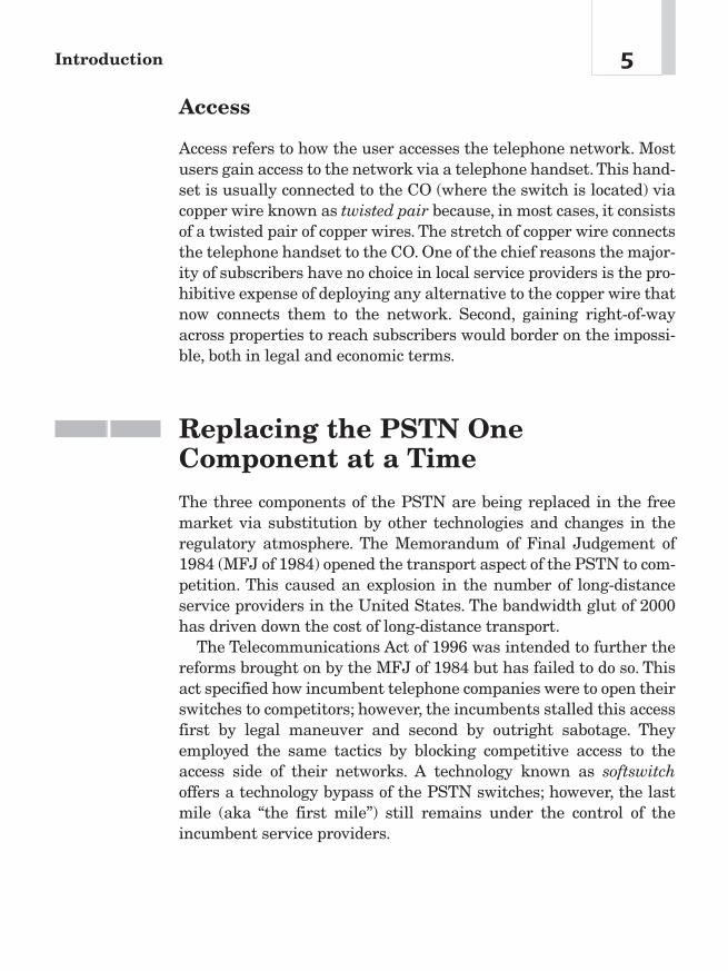
Switching
The PSTN is a star network; that is, every subscriber is connectedto another via at least one if not many hubs, known as offices. Inthese offices are switches. Very simply, local offices are for local ser-vice connection, and tandem offices are for long-distance service.Local offices, better known as central offices (COs), use Class 5switches while tandem offices use Class 4 switches. A large citymight have several COs. Denver (population two million), for exam-ple, has approximately 40 COs. COs in a large city often take upmost of a city block and are recognizable as large brick buildingswith no windows.
Transport
It took more than a century to build the PSTN at great expense.Developers have been obsessed over the years with getting the max-imum number of conversations transported at the least possible costin infrastructure. Imagine an early telephone circuit running fromNew York to Los Angeles. The copper wire, repeaters, and othermechanisms involved in transporting a conversation this distancewere immense. Hence, the early telephone engineers and scientistshad to find ways to get the maximum number of conversations trans-ported over this network. Through much research, they developeddifferent means to wring the maximum efficiency from the copperwire infrastructure. Many of those discoveries translated into tech-nologies that worked equally well when fiber optic cable came ontothe market. The primary form of transport in the PSTN has been cir-cuit switched (as opposed to the Internet’s packet switching). In the1990s, long-distance service providers, or inter exchange carriers(IXCs), and local service providers, or local exchange carriers (LECs),have migrated those transport networks to asynchronous transfermode (ATM). ATM is the means for transport from switch to switch.The emergence of Internet Protocol (IP) backbones is drawing muchtraffic from ATM networks and onto IP networks.
Chapter 14
Access
Access refers to how the user accesses the telephone network. Mostusers gain access to the network via a telephone handset. This hand-set is usually connected to the CO (where the switch is located) viacopper wire known as twisted pair because, in most cases, it consistsof a twisted pair of copper wires. The stretch of copper wire connectsthe telephone handset to the CO. One of the chief reasons the major-ity of subscribers have no choice in local service providers is the pro-hibitive expense of deploying any alternative to the copper wire thatnow connects them to the network. Second, gaining right-of-wayacross properties to reach subscribers would border on the impossi-ble, both in legal and economic terms.
Replacing the PSTN OneComponent at a TimeThe three components of the PSTN are being replaced in the freemarket via substitution by other technologies and changes in theregulatory atmosphere. The Memorandum of Final Judgement of1984 (MFJ of 1984) opened the transport aspect of the PSTN to com-petition. This caused an explosion in the number of long-distanceservice providers in the United States. The bandwidth glut of 2000has driven down the cost of long-distance transport.
The Telecommunications Act of 1996 was intended to further thereforms brought on by the MFJ of 1984 but has failed to do so. Thisact specified how incumbent telephone companies were to open theirswitches to competitors; however, the incumbents stalled this accessfirst by legal maneuver and second by outright sabotage. Theyemployed the same tactics by blocking competitive access to theaccess side of their networks. A technology known as softswitchoffers a technology bypass of the PSTN switches; however, the lastmile (aka “the first mile”) still remains under the control of theincumbent service providers.
5Introduction
Objections to Wireless NetworksThe position that wireless technologies will replace the PSTN meetswith a number of objections. Primarily, these objections are focusedon quality of service (QoS) issues, security of the wireless network,limitations in the range of the delivery of the service, and the avail-ability of bandwidth. This book will explain how these objectionshave been overcome.
QoS
One of the primary concerns about wireless data delivery, as with theInternet over wired services, is that the QoS is inadequate. Con-tention with other wireless services, lost packets, and atmosphericinterference are potential objections to WiMAX as an alternative tothe PSTN. QoS is also related to the ability of a wireless Internet ser-vice provider (WISP) to accommodate voice on its network. WiMAXutilizes a number of measures to ensure good QoS, including serviceflow QoS scheduling, dynamic service establishment, and a two-phase activation model. Figure 1-3 illustrates broadband wireless asan alternative to the PSTN infrastructure.
Security
WiMAX uses a X.509 encryption to set up the session and, onceestablished, uses 56-bit DES encryption to protect the transmission.Both measures block theft of service and ensure the privacy of thesession.
Interference Mitigation
The Radio Act of 1927 has driven the wireless regulatory frameworkin the United States. It is time for change. The current Federal Com-munications Commission (FCC) is at least somewhat aware that
Chapter 16

wireless poses a third means (after the telephone company’s copperwire and the cable TV company’s coaxial cable) of delivering resi-dential broadband and that when broadband Internet access is asubiquitous as land line telephone service is today the U.S. economycan enjoy a $500 billion annual benefit.
Economic Advantage of WiMAXWireless technologies potentially pose a cost-effective solution forservice providers, in that these technologies do not require right-of-way across private or public property to deliver service to the cus-tomer. Many businesses cannot currently receive broadband dataservices, as no fiber optic cable runs to their building(s). The cost ofsecuring permission to dig a trench through another property andrunning the requisite cable is prohibitive. With WiMAX and associ-ated technologies, it is possible to merely “beam” the data flow to thatbuilding. This solution carries over to the small office/home office(SOHO) market, in that the data flow can be beamed to homes andsmall businesses in places where no fiber optic or other high-bandwidth service exists.
7Introduction
Legacy PSTN
PSTN Bypass with WiMAX and VolP
TransportAccess AccessSwitching Switching
WiMAX phone(coming 2007) WiMAX phone
(coming 2007)WiMAX BS(Access)
WiMAX BS(Access)
Softswitch(Switching)
IP(Transport)
Figure 1-3Overview of abroadbandwirelessalternative tothe PSTN

Regulatory Aspects of WirelessNetworksWhat are the regulatory concerns when deploying a wireless enter-prise network? For a WISP? The FCC addresses wireless services inwhat is popularly known as Part 15. Wireless data requires a spec-trum on which to transmit over the airwaves at a given frequency.An unlicensed spectrum does not require the operator to obtain anexclusive license to transmit on a given frequency in a given region.Unlike the operators of radio stations or cellular telephone compa-nies, a WISP, public or private, is transmitting “for free.” AssumingWISPs ultimately compete with cell phone companies for sub-scribers, WISPs that utilize WiMAX technologies may find them-selves at a strong advantage over third-generation networks (3Gs).
Improved Quality of Life withWireless NetworksWhen deployed as a broadband IP network solution, WiMAX willenable an improved standard of living in the form of telecommuting,lower real estate prices, and improved family lives. A wave of oppor-tunity for wireless applications is in the making. Most of it lies in theform of broadband deployment. The potential for “better livingthrough telecommunications” lies largely with the ubiquitous avail-ability of broadband. In their April 2001 white paper, The $500 Bil-lion Opportunity: The Potential Economic Benefit of WidespreadDiffusion of Broadband Internet Access, Robert Crandall andCharles Jackson point to an economic benefit of $500 billion per yearfor the American economy if broadband Internet access were to be asubiquitous as land line phones.1
Chapter 18
1Robert W. Crandall and Charles L. Jackson. “The $500 Billion Opportunity: ThePotential Economic Benefit of Widespread Diffusion of Broadband Internet Access.”Washington, DC: Criterion Economics, LLC, 2001.Available at www.criterioneconom-ics.com.
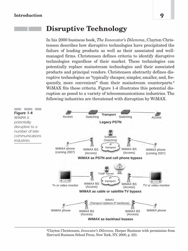
Disruptive TechnologyIn his 2000 business book, The Innovator’s Dilemma, Clayton Chris-tensen describes how disruptive technologies have precipitated thefailure of leading products as well as their associated and well-managed firms. Christensen defines criteria to identify disruptivetechnologies regardless of their market. These technologies canpotentially replace mainstream technologies and their associatedproducts and principal vendors. Christensen abstractly defines dis-ruptive technologies as “typically cheaper, simpler, smaller, and, fre-quently, more convenient” than their mainstream counterparts.2
WiMAX fits these criteria. Figure 1-4 illustrates this potential dis-ruption as posed to a variety of telecommunications industries. Thefollowing industries are threatened with disruption by WiMAX.
9Introduction
Legacy PSTN
WiMAX as PSTN and cell phone bypass
TransportAccess AccessSwitching Switching
WiMAX phone(coming 2007)
WiMAX phone(coming 2007)
WiMAX BS(Access)
WiMAX BS(Access)
Softswitch(Switching)
IPtransport
WiMAX as cable or satellite TV bypass
WiMAX as backhaul bypass
WiMAX(Transport-replaces IP backbone)
IPtransport
Tv or video monitor TV or video monitorWiMAX BS(Access)
WiMAX BS(Access)
WiMAX phone WiMAX phoneWiMAX BS(Access)
WiMAX BS(Access)
TVolP Server
Figure 1-4WiMAX ispotentiallydisruptive to anumber of tele-communicationsindustries.
2Clayton Christensen, Innovator’s Dilemma, Harper Business with permission fromHarvard Business School Press, New York, NY, 2000, p. 221.

Disruption for Telephone Companies
Figure 1-1 demonstrated how WiMAX replaces the access portion ofthe PSTN. The broadband Internet connection made possible byWiMAX is IP and, using Voice over Internet Protocol (VoIP), thePSTN is bypassed.With the possible exception of terminating a voicecall to a PSTN number, calls need not touch the PSTN. This is poten-tially very disruptive to incumbent telephone companies. Refer toFigure 1-2 for an illustration.
Disruption for Cable TV and Satellite TVCompanies
A technology called TV over Internet Protocol (TvoIP) does for cableTV what VoIP does for telephone companies. It is now possible tosimply convert cable TV programming and deliver it over a broad-band Internet connection such as WiMAX. The programming isavailable in real time identical to the cable TV broadcast, and chan-nels can be changed using a set top box while programming is dis-played on a conventional TV set. No PC skills are required.
Disruption for Cell Phone Companies
VoIP technologies can be used for mobile telephony to replace incum-bent cell phone technologies. It will soon be possible to replace anincumbent cell phone infrastructure for a small fraction of the cost ofbuilding the incumbent cell phone network. All that is really neces-sary is a WiMAX mobile phone and access to a WiMAX base station(the same base stations that deliver broadband Internet access,VoIP,and TvoIP to residences and businesses).
Disruption for the Backhaul Industry
The building of multibillion dollar fiber optic networks marked thetelecommunications boom of the 1990s. Very simply put, if WiMAXcan beam 72 Mbps over 30 miles and the infrastructure costs only a
Chapter 110
few thousand dollars (radios, antennas), then services that backhaul(or transport) data via fiber optic cables and charge their customersthousands of dollars per month to do so are in jeopardy. This modelcan be extended to long-distance backhaul as well. Microwave towershave long been the means of long-distance backhaul for telephonecompanies. WiMAX is a means of simply expanding or augmentingthese networks.
ConclusionAs of 2005, despite the guarantees contained in the Telecommunica-tions Act of 1996, it appears obvious that competition will nevercome in the local loop but can only come to the local loop in the formof an alternative network. Consumers will only enjoy the benefits ofcompetition in the local loop when and where alternative technologyin switching and access offer a competitor lower barriers to entryand exit in the telecommunications market. If telecommunicationsconsumers are to enjoy the benefits of competition in their local loop,a form of bypass of the switching architecture and the means ofaccess (copper wires from the telephone company) must be offered.
11Introduction

This page intentionally left blank

WiMAX: ThePhysical Layer
(PHY)
CHAPTER 22
Copyright © 2005 by The McGraw-Hill Companies, Inc. Click here for terms of use.

IntroductionWiMAX is not truly new; rather, it is unique because it was designedfrom the ground up to deliver maximum throughput to maximumdistance while offering 99.999 percent reliability. To achieve this, thedesigners (IEEE 802.16 Working Group D) relied on proven tech-nologies for the PHY including orthogonal frequency division multi-plexing (OFDM), time division duplex (TDD), frequency divisionduplex (FDD), Quadrature Phase Shift Keying (QPSK), and Quad-rature Amplitude Modulation (QAM), to name only a few. This chap-ter will provide a brief overview of the PHY and different variants(based on their PHY technologies and applications) of WiMAX, thetechnologies that make these variants work, and reasons why thesetechnologies combine to make WiMAX a quantum leap over previouswireless technologies.
Chapter 214
APPLICATION
PRESENTATION
SESSION
TRANSPORT
NETWORK
IEEE 802.2Logical Link Control (LLC)
IEEE 802.11Media Access Control (MAC)
FrequencyHoppingSpreadSpectrum(FHSS)PHY Layer
DirectSequenceSpreadSpectrum(DSSS)PHY Layer
Infrared PHY
(Data Link)
(PHYSICAL)
Figure 2-1IEEE 802.11MAC andphysical layers(Source:McGraw-Hill)
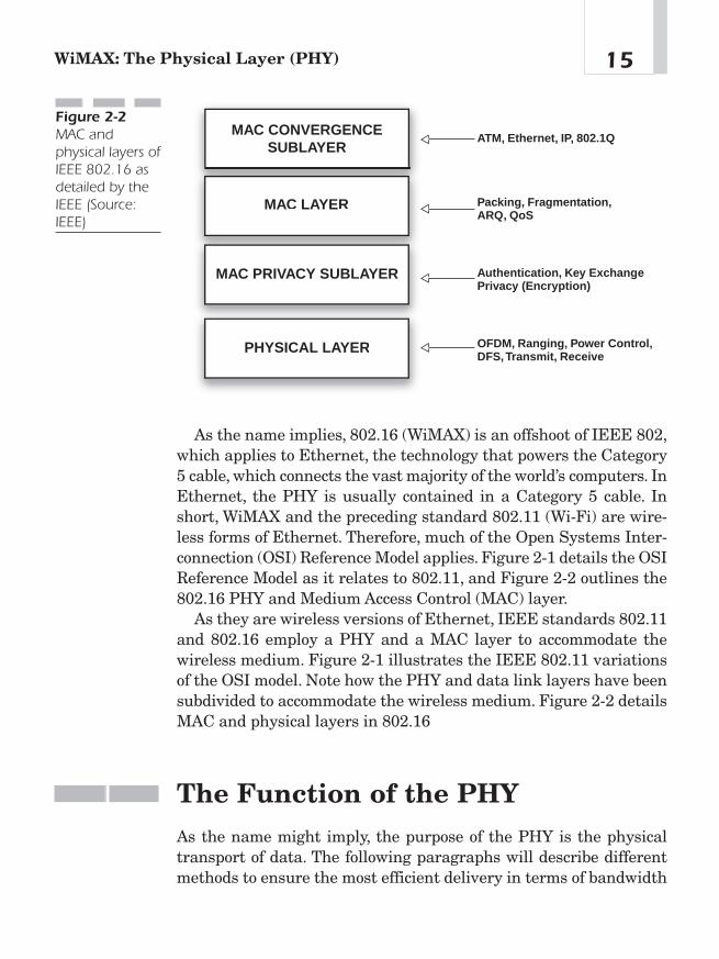
As the name implies, 802.16 (WiMAX) is an offshoot of IEEE 802,which applies to Ethernet, the technology that powers the Category5 cable, which connects the vast majority of the world’s computers. InEthernet, the PHY is usually contained in a Category 5 cable. Inshort, WiMAX and the preceding standard 802.11 (Wi-Fi) are wire-less forms of Ethernet. Therefore, much of the Open Systems Inter-connection (OSI) Reference Model applies. Figure 2-1 details the OSIReference Model as it relates to 802.11, and Figure 2-2 outlines the802.16 PHY and Medium Access Control (MAC) layer.
As they are wireless versions of Ethernet, IEEE standards 802.11and 802.16 employ a PHY and a MAC layer to accommodate thewireless medium. Figure 2-1 illustrates the IEEE 802.11 variationsof the OSI model. Note how the PHY and data link layers have beensubdivided to accommodate the wireless medium. Figure 2-2 detailsMAC and physical layers in 802.16
The Function of the PHYAs the name might imply, the purpose of the PHY is the physicaltransport of data. The following paragraphs will describe differentmethods to ensure the most efficient delivery in terms of bandwidth
15WiMAX: The Physical Layer (PHY)
ATM, Ethernet, IP, 802.1Q
Packing, Fragmentation,ARQ, QoS
Authentication, Key ExchangePrivacy (Encryption)
OFDM, Ranging, Power Control, DFS, Transmit, Receive
MAC CONVERGENCESUBLAYER
MAC LAYER
MAC PRIVACY SUBLAYER
PHYSICAL LAYER
Figure 2-2MAC andphysical layers ofIEEE 802.16 asdetailed by theIEEE (Source:IEEE)

(volume and time in Mbps) and frequency spectrum (MHz/GHz). Anumber of legacy technologies are used to get the maximum perfor-mance out of the PHY. These technologies, including OFDM, TDD,FDD, QAM, and Adaptive Antenna System (AAS), will be describedin the following pages or chapters.
OFDM: The “Big So What?!” of WiMAX
OFDM is what puts the max in WiMAX. OFDM is not new. Bell Labsoriginally patented it in 1970, and it became incorporated in variousdigital subscriber line (DSL) technologies as well as in 802.11a.OFDM is based on a mathematical process called Fast FourierTransform (FFT), which enables 52 channels to overlap without los-ing their individual characteristics (orthogonality). This is a moreefficient use of the spectrum and enables the channels to beprocessed at the receiver more efficiently. OFDM is especially popu-lar in wireless applications because of its resistance to forms of inter-ference and degradation (multipath and delay spread, more on thisin Chapter 6). In short, OFDM delivers a wireless signal much far-ther with less interference than competing technologies. Figure 2-3provides an illustration of how OFDM works.
Chapter 216
Limited distance and throughput; Susceptible to interference
Base Station
Base Station
SubscriberStation
SubscriberStation
MAXIMUM DISTANCE AND THROUGHPUT;
RESISTANT TO INTERFERENCE
Non-OFDM
OFDM
Figure 2-3The significanceof OFDM: Afocused beamdeliveringmaximumbandwidth overmaximumdistance withminimuminterference

TDD and FDD
WiMAX supports both time division duplex (TDD) and frequencydivision duplex (FDD) operation. TDD is a technique in which thesystem transmits and receives within the same frequency channel,assigning time slices for transmit and receive modes. FDD requirestwo separate frequencies generally separated by 50 to 100 MHzwithin the operating band. TDD provides an advantage where a reg-ulator allocates the spectrum in an adjacent block. With TDD, bandseparation is not needed, as is shown in Figure 2-4. Thus, the entirespectrum allocation is used efficiently both upstream and down-stream and where traffic patterns are variable or asymmetrical.
In FDD systems, the downlink (DL) and uplink (UL) frame struc-tures are similar except that the DL and UL are transmitted on sep-arate channels. When half-duplex FDD (H-FDD) subscriber stations(SSs) are present, the base station (BS) must ensure that it does notschedule an H-FDD SS to transmit and receive at the same time.1
Figure 2-5 illustrates this relationship.
17WiMAX: The Physical Layer (PHY)
Frame Header Downlink Subframe TG Uplink SubframeFigure 2-4A TDD subframe
Uplink: "Hello Base Station! This is a subscriber station checking in.
Send some data!"
Downlink: "Welcome Subscriber Station! Here you go!"
SubscriberStation(SS)
Base Station(BS)
Figure 2-5ULs and DLsbetween BSsand SSs
1Govindan Nair, Joey Chou, Tomaz Madejski, Krzysztof Perycz, David Putzolu, andJerry Sydir, “IEEE 802.16 Medium Access Control and Service Provisioning,” IntelTechnology Journal 3, no. 3 (August 20, 2004): 216—217.

Adaptive Antenna System (AAS)
AAS is used in the WiMAX specification to describe beam-formingtechniques where an array of antennas is used at the BS to increasegain to the intended SS while nulling out interference to and fromother SSs and interference sources. AAS techniques can be used toenable Spatial Division Multiple Access (SDMA), so multiple SSsthat are separated in space can receive and transmit on the samesubchannel at the same time. By using beam forming, the BS is ableto direct the desired signal to the different SSs and can distinguishbetween the signals of different SSs, even though they are operatingon the same subchannel(s), as shown in Figure 2-6.
WiMAX VariantsWiMAX has five variants, which are specified by their PHY. Thevariants are divided by whether the variant is single carrier (SC) oruses OFDM. They are further broken down into the frequency bandsthey cover: 2—11 GHz and 10—66 GHz. The following paragraphs give
Chapter 218
Base Station
Figure 2-6AAS uses beamforming toincrease gain(energy) to theintended SS.

a brief overview of each variant with emphasis on Wireless metroarea network—OFDM (aka WirelessMAN-OFDM). Much of the fol-lowing is for reference purposes, and the less technical reader maywant to move on to Chapter 3 at this time. Table 2-1 provides anoverview of these variants.
OFDM Variants 2–11 GHz
The need for NLOS operation drives the design of the 2—11 GHzPHY. Because residential applications are expected, rooftops may betoo low (possibly due to obstruction by trees or other buildings) for aclear sight line to a BS antenna. Therefore, significant multipathpropagation must be expected. Furthermore, outdoor-mountedantennas are expensive, due to both hardware and installation costs.The four 2—11 GHz air interface specifications are described in thefollowing paragraphs.
WirelessMAN-OFDM This air interface uses OFDM with a 256-point transform (see OFDM description later in this chapter). Accessis by TDMA. This air interface is mandatory for license-exemptbands.
19WiMAX: The Physical Layer (PHY)
Designation Function LOS/ Frequency Duplexing
NLOS Alternative(s)
WirelessMAN- Point-to-point LOS 10–66 GHz TDD, FDDSC
WirelessMAN- Point-to-point NLOS 2–11 GHz TDD FDDSCa
WirelessMAN Point-to- NLOS 2–11 GHz TDD FDDOFDM mulitpoint
WirelessMAN- Point-to- NLOS 2–11 GHz TDD FDDOFDMA mulitpoint
Wireless Point-to- NLOS 2–11 GHz TDDHUMAN mulitpoint
Table 2-1
Variants ofWiMAX PHY
The WirelessMAN-OFDM PHY is based on OFDM modulation. Itis intended mainly for fixed access deployments where SSs are resi-dential gateways deployed within homes and businesses. TheOFDM PHY supports subchannelization in the UL. There are 16subchannels in the UL. The OFDM PHY supports TDD and FDDoperations, with support for both FDD and H-FDD SSs. The stan-dard supports multiple modulation levels including Binary PhaseShift Keying (BPSK), QPSK, 16-QAM, and 64-QAM. Finally, thePHY supports (as options) transmit diversity in the DL using SpaceTime Coding (STC) and AAS with Spatial Division Multiple Access(SDMA).
The transmit diversity scheme uses two antennas at the BS totransmit an STC-encoded signal to provide the gains that resultfrom second-order diversity. Each of two antennas transmits a dif-ferent symbol (two different symbols) in the first symbol time. Thetwo antennas then transmit the complex conjugate of the same twosymbols in the second symbol time. The resulting data rate is thesame as without transmit diversity.
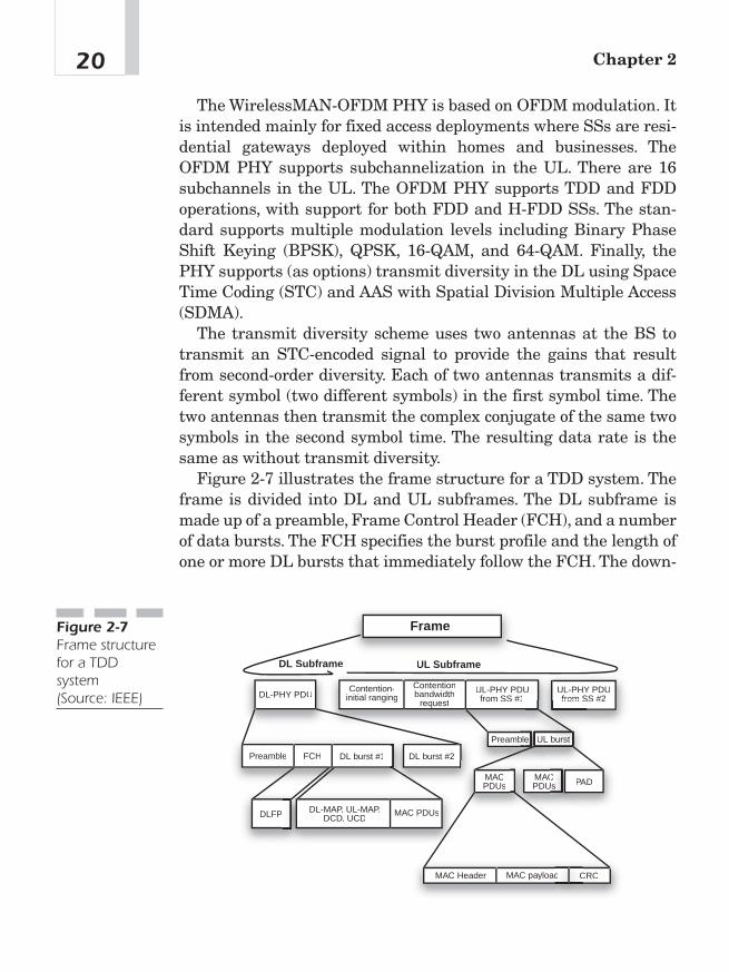
Figure 2-7 illustrates the frame structure for a TDD system. Theframe is divided into DL and UL subframes. The DL subframe ismade up of a preamble, Frame Control Header (FCH), and a numberof data bursts. The FCH specifies the burst profile and the length ofone or more DL bursts that immediately follow the FCH. The down-
Chapter 220
Frame
DL Subframe UL Subframe
DL-PHY PDUContention-
initial rangingContentionbandwidth
request
UL-PHY PDUfrom SS #1
UL-PHY PDUfrom SS #2from S
Preamble
Preambblee
FCH DL burst #1 DL burst #2
UL burst
MACPDUs
MACCPDUs PAD
DLFP DL-MAP, UL-MAP,DCD, UCD
MAC PDUs
MAC Header MAC payloadd CRCC
Figure 2-7Frame structurefor a TDDsystem(Source: IEEE)
link map (DL-MAP), uplink map (UL-MAP), DL Channel Descriptor(DCD), UL Channel Descriptor (UCD), and other broadcast mes-sages that describe the content of the frame are sent at the begin-ning of these first bursts. The remainder of the DL subframe is madeup of data bursts to individual SSs.
Each data burst consists of an integer number of OFDM symbolsand is assigned a burst profile that specifies the code algorithm, coderate, and modulation level that are used for those data transmittedwithin the burst.The UL subframe contains a contention interval forinitial ranging and bandwidth allocation purposes and UL PHY pro-tocol data units (PDUs) from different SSs. The DL-MAP and UL-MAP completely describe the contents of the DL and UL subframes.They specify the SSs that are receiving and/or transmitting in eachburst, the subchannels on which each SS is transmitting (in the UL),and the coding and modulation used in each burst and in each sub-channel.
If transmit diversity is used, a portion of the DL frame (called azone) can be designated to be a transmit diversity zone. All databursts within the transmit diversity zone are transmitted using STCcoding. Finally, if AAS is used, a portion of the DL subframe can bedesignated as the AAS zone. Within this part of the subframe, AASis used to communicate to AAS-capable SSs.AAS is also supported inthe UL.
WirelessMAN-OFDMA This variant uses orthogonal frequencydivision multiple access (OFDMA) with a 2048-point transform (afunction of OFDM, see Chapter 5 for a description). In this system,addressing a subset of the multiple carriers to individual receiversprovides multiple access. Because of the propagation requirements,the use of AASs is supported.
The WirelessMAN-OFDMA PHY is based on OFDM modulation.It supports subchannelization in both the UL and DL. The standardsupports five different subchannelization schemes. The OFDMAPHY supports both TDD and FDD operations. The same modulationlevels are also supported. STC and AAS with SDMA are supported,as is multiple input, multiple output (MIMO). MIMO encompasses anumber of techniques for utilizing multiple antennas at the BS andSS in order to increase the capacity and range of the channel.
21WiMAX: The Physical Layer (PHY)

The frame structure in the OFDMA PHY is similar to the struc-ture of the OFDM PHY. The notable exceptions are that subchan-nelization is defined in the DL as well as in the UL, so broadcastmessages are sometimes transmitted at the same time (on differentsubchannels) as data. Also, because a number of different subchan-nelization schemes are defined, the frame is divided into a number ofzones that each use a different subchannelization scheme. The MAClayer is responsible for dividing the frame into zones and communi-cating this structure to the SSs in the DL-MAP and UL-MAP. As inthe OFDM PHY, there are optional transmit diversity and AASzones, as well as a MIMO zone.2
Wireless High Speed Unlicensed Metro Area Network (Wire-lessHUMAN) WirelessHUMAN is similar to the aforementionedOFDM-based schemes and is focused on Unlicensed National Infor-mation Infrastructure (UNII) devices and other unlicensed bands.
Single Carrier (SC) Variants
There are two single carrier variants of WiMAX. These variants arefounded on frequency division duplexing and time division duplexing.
WirelessMan-SC 10–66 GHz In this point-to-multipoint archi-tecture, the BS basically transmits a time division multiplexing(TDM) signal, with individual SS allocated time slots serially. Wire-lessMAN-SC 10—66 GHz utilizes a burst design that allows bothTDD, in which the UL and DL share a channel but do not transmitsimultaneously, and FDD, in which the UL and DL sometimes oper-ate simultaneously on separate channels. This burst design allowsboth TDD and FDD to be handled similarly. Moreover, both TDD andFDD alternatives support adaptive burst profiles in which modula-tion and coding options may be dynamically assigned on a burst-by-burst basis. Chapter 5 describes this procedure in greater detail.
Chapter 222
2Ibid., 216.
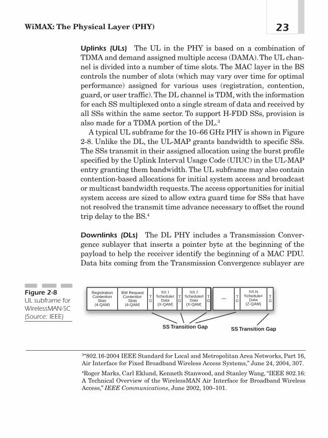
Uplinks (ULs) The UL in the PHY is based on a combination ofTDMA and demand assigned multiple access (DAMA).The UL chan-nel is divided into a number of time slots. The MAC layer in the BScontrols the number of slots (which may vary over time for optimalperformance) assigned for various uses (registration, contention,guard, or user traffic). The DL channel is TDM, with the informationfor each SS multiplexed onto a single stream of data and received byall SSs within the same sector. To support H-FDD SSs, provision isalso made for a TDMA portion of the DL.3
A typical UL subframe for the 10—66 GHz PHY is shown in Figure2-8. Unlike the DL, the UL-MAP grants bandwidth to specific SSs.The SSs transmit in their assigned allocation using the burst profilespecified by the Uplink Interval Usage Code (UIUC) in the UL-MAPentry granting them bandwidth. The UL subframe may also containcontention-based allocations for initial system access and broadcastor multicast bandwidth requests. The access opportunities for initialsystem access are sized to allow extra guard time for SSs that havenot resolved the transmit time advance necessary to offset the roundtrip delay to the BS.4
Downlinks (DLs) The DL PHY includes a Transmission Conver-gence sublayer that inserts a pointer byte at the beginning of thepayload to help the receiver identify the beginning of a MAC PDU.Data bits coming from the Transmission Convergence sublayer are
23WiMAX: The Physical Layer (PHY)
3“802.16-2004 IEEE Standard for Local and Metropolitan Area Networks, Part 16,Air Interface for Fixed Broadband Wireless Access Systems,” June 24, 2004, 307.4Roger Marks, Carl Eklund, Kenneth Stanwood, and Stanley Wang, “IEEE 802.16:A Technical Overview of the WirelessMAN Air Interface for Broadband WirelessAccess,” IEEE Communications, June 2002, 100—101.
SS Transition Gap SS Transition Gap
RegistrationContention
Slots(4-QAM)
BW RequestContention
Slots(4-QAM)
TG
TG
TG
TG
TG
SS 1Scheduled
Data(X-QAM)
SS 2Scheduled
Data(X-QAM)
***
SS NScheduled
Data(Z-QAM)
Figure 2-8UL subframe forWirelessMAN-SC(Source: IEEE)

randomized, forward error correction (FEC) encoded, and mapped toa QPSK, 16-QAM, or 64-QAM (optional) signal constellation.5 (Mod-ulation schemes will be covered in detail in Chapter 5.) In the struc-ture for a burst FDD DL frame, each frame is subdivided into anumber of physical slots, and each slot represents four modulationsymbols. The frame starts with a TDM section that is organized intodifferent modulation and FEC groups. The groups contain datatransmitted to full-duplex stations. The last section of the frame isthe TDMA section, which contains data transmitted to the half-duplex stations.
Each burst upstream frame contains three types of slots: (1) con-tention slots used for registration, (2) contention slots used for band-width/channel requests, and (3) slots reserved for individualstations. Each type of slot carries the modulation scheme that it issupposed to support, and different stations can be assigned differentmodulation schemes. The contention slots use 4-QAM, but thereserved slots can be assigned any modulation scheme.
In continuous FDD, the upstream channel is partitioned into aseries of minislots, and each minislot consists of a group of physicalslots. As stated earlier, a physical slot consists of four modulationsymbols.The BS periodically broadcasts the upstream MAP messageon the downstream channel. The upstream MAP message definesthe permissible usage of each upstream minislot within the timeinterval covered by the MAP message. Upstream MAP messages aretransmitted approximately 250 times per second. This is illustratedin Figure 2-9.
Chapter 224
5“Air Interface for Fixed Broadband Wireless Access Systems,” 307.
Transmission Convergence Sublayer PDU
P MAC PDU that has startedin previous TC PDU
First MAC PDU, this TCPDU
Second MAC PDU, this TCPDU
Figure 2-9TC sublayer and the MACPDU in theWirelessMAN-SC PHY(Source: IEEE)
The FEC used in WiMAX is Reed-Solomon GF(256), with variableblock size and error correction capabilities. This is paired with aninner block convolutional code to robustly transmit critical data suchas frame control and initial accesses. The FEC options are pairedwith QPSK, 16-QAM, and 64-QAM to form burst profiles of varyingrobustness and efficiency. If the last FEC block is not filled, thatblock may be shortened. Shortening in both the UL and DL is con-trolled by the BS and is communicated in the UL-MAP and DL-MAP.
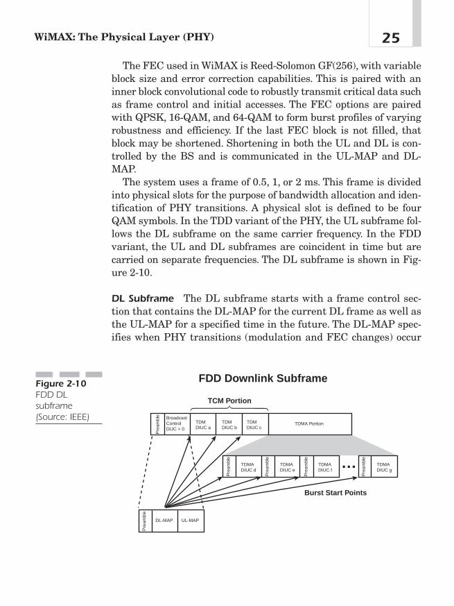
The system uses a frame of 0.5, 1, or 2 ms. This frame is dividedinto physical slots for the purpose of bandwidth allocation and iden-tification of PHY transitions. A physical slot is defined to be fourQAM symbols. In the TDD variant of the PHY, the UL subframe fol-lows the DL subframe on the same carrier frequency. In the FDDvariant, the UL and DL subframes are coincident in time but arecarried on separate frequencies. The DL subframe is shown in Fig-ure 2-10.
DL Subframe The DL subframe starts with a frame control sec-tion that contains the DL-MAP for the current DL frame as well asthe UL-MAP for a specified time in the future. The DL-MAP spec-ifies when PHY transitions (modulation and FEC changes) occur
25WiMAX: The Physical Layer (PHY)
TCM Portion
Burst Start Points
FDD Downlink Subframe
Pre
ambl
e
Pre
ambl
e
Pre
ambl
e
Pre
ambl
e
Pre
ambl
e
Pre
ambl
e
BroadcastControlDIJC = 0
TDMDIUC a
TDMDIUC b
TDMDIUC c
TDMADIUC d
TDMADIUC e
TDMADIUC f
TDMADIUC g
TDMA Portion
DL-MAP UL-MAP
Figure 2-10FDD DLsubframe(Source: IEEE)
within the DL subframe. The DL subframe typically contains aTDM portion immediately following the frame control section. DLdata are transmitted to each SS using a negotiated burst profile.The data are transmitted in order of decreasing robustness to allowSSs to receive their data before being presented with a burst pro-file that could cause them to lose synchronization with the DL.
In FDD systems, a TDMA segment that includes an extra pream-ble at the start of each new burst profile may follow the TDM por-tion. This feature allows better support of half-duplex SSs. In anefficiently scheduled FDD system with many half-duplex SSs, someSSs may need to transmit earlier in the frame than they receive. Dueto their half-duplex nature, these SSs lose synchronization with theDL. The TDMA preamble allows them to regain synchronization.
Due to the dynamics of bandwidth demand for the variety of ser-vices that may be active, the mixture and duration of burst profilesand the presence or absence of a TDMA portion vary dynamicallyfrom frame to frame. Because the recipient SS is implicitly indicatedin the MAC headers rather than in the DL-MAP, SSs listen to allportions of the DL subframe they are capable of receiving. For full-duplex SSs, this means receiving all burst profiles of equal or greaterrobustness than they have negotiated with the BS.
WirelessMAN–Single Carrier Access (WirelessMAN-SCa) 2–11GHz This variant uses a single-carrier modulation format in the2—11 GHz spectrum and is designed for NLOS operations. Five con-cepts define the WirelessMAN-SCa variant of the PHY. Elementswithin this PHY include TDD and FDD definitions (one of whichmust be supported), TDMA UL, TDM or TDMA DL, and block adap-tive modulation. The PHY also includes FEC coding for both UL andDL and framing structures that enable improved equalization, chan-nel estimation performance over NLOS and extended delay spreadenvironments, parameter settings, and MAC/PHY messages thatfacilitate optional AAS implementations.6 Table 2-2 further defineselements in this sub specification.
Chapter 226
6Ibid.
ConclusionIf there were one word to describe the WiMAX PHY, it would berobust. That is, it uses tested legacy technologies to deliver maxi-mum bandwidth over maximum distances with minimum loss tointerference. Because multiple variants of the PHY have been builtinto the specification, the standard can be applied to multiple roleswithin a wireless network. For example, the SC variant is well suitedfor point-to-point backhaul applications, and the OFDM variant iswell suited for last-mile point-to-multipoint applications. Together,these variants and their underlying technologies are the buildingblocks for a next generation broadband wireless network.
27WiMAX: The Physical Layer (PHY)
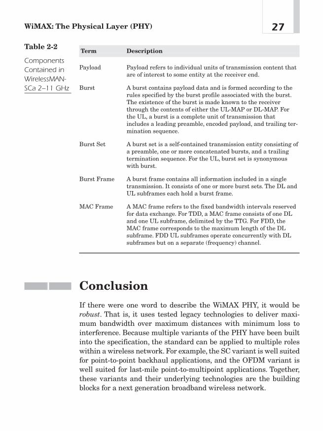
Term Description
Payload Payload refers to individual units of transmission content thatare of interest to some entity at the receiver end.
Burst A burst contains payload data and is formed according to therules specified by the burst profile associated with the burst.The existence of the burst is made known to the receiverthrough the contents of either the UL-MAP or DL-MAP. Forthe UL, a burst is a complete unit of transmission thatincludes a leading preamble, encoded payload, and trailing ter-mination sequence.
Burst Set A burst set is a self-contained transmission entity consisting ofa preamble, one or more concatenated bursts, and a trailingtermination sequence. For the UL, burst set is synonymouswith burst.
Burst Frame A burst frame contains all information included in a singletransmission. It consists of one or more burst sets. The DL andUL subframes each hold a burst frame.
MAC Frame A MAC frame refers to the fixed bandwidth intervals reservedfor data exchange. For TDD, a MAC frame consists of one DLand one UL subframe, delimited by the TTG. For FDD, theMAC frame corresponds to the maximum length of the DLsubframe. FDD UL subframes operate concurrently with DLsubframes but on a separate (frequency) channel.
Table 2-2
ComponentsContained inWirelessMAN-SCa 2–11 GHz

This page intentionally left blank

The MediumAccess Control(MAC) Layer
CHAPTER 33
Copyright © 2005 by The McGraw-Hill Companies, Inc. Click here for terms of use.

The MAC as the “Smarts” for thePhysical LayerThe WiMAX MAC provides intelligence for the PHY and ensures anumber of QoS measures not seen on other wireless standards. Per-haps its greatest value is providing for dynamic bandwidth alloca-tion that defeats the usual degradations of wireless services—jitterand latency.
The WiMAX MAC protocol was designed for point-to-multipointbroadband wireless access applications. It addresses the need forvery high bit rates, both UL (to the BS) and DL (from the BS). WithWiMAX, unlike with its Wi-Fi predecessors, access and bandwidthallocation algorithms accommodate hundreds of terminals per chan-nel, and multiple end users might share those terminals. End usersrequire services that are varied in nature including legacy TDMvoice and data, IP connectivity, and packetized VoIP. To supportthese various services, the WiMAX MAC accommodates both contin-uous and bursty traffic. Additionally, these services expect to beassigned QoS parameters in keeping with the traffic types.
The WiMAX MAC protocol supports a variety of backhaulrequirements including both ATM and packet-based protocols. Con-vergence sublayers map the transport-layer-specific traffic to a MACthat is flexible enough to efficiently carry any traffic type. The con-vergence sublayers and MAC work together using payload headersuppression, packing, and fragmentation to carry traffic more effi-ciently than the original transport mechanism.
The MAC and WiMAX ArchitectureThe WiMAX DL from the BS to the user operates on a point-to-multipoint basis as illustrated in Figure 3-1. The WiMAX wirelesslink operates with a central BS with a sectorized antenna that iscapable of handling multiple independent sectors simultaneously.Within a given frequency channel and antenna sector, all stationsreceive the same transmission. The BS is the only transmitter oper-
Chapter 330
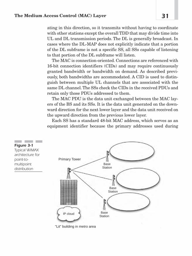
ating in this direction, so it transmits without having to coordinatewith other stations except the overall TDD that may divide time intoUL and DL transmission periods. The DL is generally broadcast. Incases where the DL-MAP does not explicitly indicate that a portionof the DL subframe is not a specific SS, all SSs capable of listeningto that portion of the DL subframe will listen.
The MAC is connection-oriented. Connections are referenced with16-bit connection identifiers (CIDs) and may require continuouslygranted bandwidth or bandwidth on demand. As described previ-ously, both bandwidths are accommodated. A CID is used to distin-guish between multiple UL channels that are associated with thesame DL channel. The SSs check the CIDs in the received PDUs andretain only those PDUs addressed to them.
The MAC PDU is the data unit exchanged between the MAC lay-ers of the BS and its SSs. It is the data unit generated on the down-ward direction for the next lower layer and the data unit received onthe upward direction from the previous lower layer.
Each SS has a standard 48-bit MAC address, which serves as anequipment identifier because the primary addresses used during
31The Medium Access Control (MAC) Layer
Primary Tower
"Lit" building in metro area
BaseStation
BaseStation
BaseStation
IP cloud
Figure 3-1Typical WiMAXarchitecture forpoint-to-multipointdistribution
operation are the CIDs. Upon entering the network, the SS isassigned three management connections in each direction. Thesethree connections reflect the three different QoS requirements usedby different management levels:
■ Basic connection—transfers short, time-critical MAC andradio link control (RLC) messages (see Chapter 4).
■ Primary management connection—transfers longer, moredelay-tolerant messages, such as those used for authenticationand connection setup. The secondary management connectiontransfers standards-based management messages such asDynamic Host Configuration Protocol (DHCP), Trivial FileTransfer Protocol (TFTP), and Simple Network ManagementProtocol (SNMP). In addition to these management connections,SSs are allocated transport connections for the contractedservices.
■ Transport connections—are unidirectional to facilitatedifferent UL and DL QoS and traffic parameters; they aretypically assigned to services in pairs.
SSs share the UL to the BS on a demand basis. Depending on theclass of service utilized, the SS may be issued continuing rights totransmit, or the BS may grant the right to transmit after receivinga request from the user.
Service Classes and QoS
Within each sector, users adhere to a transmission protocol that con-trols contention between users and enables the service to be tailoredto the delay and bandwidth requirements of each user application.This is accomplished through four different types of UL schedulingmechanisms. These mechanisms are implemented using unsolicitedbandwidth grants, polling, and contention procedures. The WiMAXMAC provides QoS differentiation for different types of applicationsthat might operate over WiMAX networks:
■ Unsolicited Grant Services (UGS)—UGS is designed tosupport constant bit rate (CBR) services, such as T1/E1 emulationand VoIP without silence suppression.
Chapter 332
■ Real-Time Polling Services (rtPS)—rtPS is designed tosupport real-time services that generate variable size datapackets, such as MPEG video or VoIP with silence suppression,on a periodic basis.
■ Non-Real-Time Polling Services (nrtPS)—nrtPS is designedto support non-real-time services that require variable size datagrant burst types on a regular basis.
■ Best Effort (BE) Services—BE services are typically providedby the Internet today for web surfing.
The use of polling simplifies the access operation and guaranteesthat applications receive service on a deterministic basis if required.In general, data applications are delay tolerant, but real-time appli-cations, like voice and video, require service on a more uniform basisand sometimes on a very tightly controlled schedule.
For the purposes of mapping to services on SSs and associatingvarying levels of QoS, all data communications are in the context ofa connection. Service flows may be provisioned when an SS isinstalled in the system. Shortly after SS registration, connectionsare associated with these service flows (one connection per serviceflow) to provide a reference against which to request bandwidth.Additionally, new connections may be established when a customer’sservice needs change. A connection defines both a service flow andthe mapping between peer convergence processes that utilize theMAC. The service flow defines the QoS parameters for the PDUsthat are exchanged once the connection has been established.
Service flows are the mechanism for UL and DL for QoS manage-ment. In particular, they facilitate the bandwidth allocation process.An SS requests UL bandwidth on a per connection basis (implicitlyidentifying the service flow). The BS grants the bandwidth to an SSas an aggregate of grants in response to per connection requestsfrom the SS.1
The modulation and coding schemes are specified in a burst pro-file that may be adjusted adaptively for each burst to each SS. The
33The Medium Access Control (MAC) Layer
1“802.16-2004 IEEE Standard for Local and Metropolitan Area Networks, Part 16,AirInterface for Fixed Broadband Wireless Access Systems,” June 24, 2004, 31.
MAC can make use of bandwidth-efficient burst profiles under favor-able link conditions then shift to more reliable, although less effi-cient alternatives, as required to support the planned 99.999 percentlink availability (QPSK to 16-QAM to 64-QAM).
The request-grant mechanism is designed to be scalable, efficient,and self-correcting. The WiMAX access system does not lose effi-ciency when presented with multiple connections per terminal, mul-tiple QoS levels per terminal, and a large number of statisticallymultiplexed users.
Along with the fundamental task of allocating bandwidth andtransporting data, the MAC includes a privacy sublayer that pro-vides authentication of network access and connection establish-ment to avoid theft of service, and it provides key exchange andencryption for data privacy.
Service-Specific ConvergenceSublayersThe WiMAX standard defines two general service-specific conver-gence sublayers for mapping services to and from WiMAX MAC con-nections:
■ The ATM convergence sublayer is for ATM services.
■ The packet convergence sublayer is defined for mapping packetservices such as Internet Protocol version 4 or 6 (IPv4, IPv6),Ethernet, and virtual local area network (VLAN).
The primary task of the sublayer is to classify service data units(SDUs) to the proper MAC connection, preserve or enable QoS, andenable bandwidth allocation. SDUs are the units exchanged betweentwo adjacent protocol layers. They are the data units received on thedownward direction from the previous higher layer and the dataunits sent on the upward direction to the next higher layer.The map-ping takes various forms, depending on the type of service. In addi-tion to these basic functions, the convergence sublayers performsophisticated functions, such as payload header suppression andreconstruction, to enhance airlink efficiency.
Chapter 334

Common Part Sublayer
The MAC reserves additional connections for other purposes. Oneconnection is reserved for contention-based initial access. Another isreserved for broadcast transmissions in the DL as well as for signal-ing broadcast contention-based polling of SS bandwidth needs. Addi-tional connections are reserved for multicast, rather than broadcast,contention-based polling. SSs may be instructed to join multicastpolling groups associated with these multicast polling connections.
MAC PDU Formats A MAC PDU consists of a fixed-length MACheader, a variable-length payload, and an optional cyclic redundancycheck (CRC). Two header formats are defined: the generic header (asillustrated in Figure 3-2) and the bandwidth request header. Exceptfor bandwidth request MAC PDUs, which contain no payload, MACPDUs contain either MAC management messages or convergencesublayer data.
There are three types of MAC subheaders:
■ Grant management subheader—is used by an SS to conveybandwidth management needs to its BS.
■ Fragmentation subheader—contains information thatindicates the presence and orientation in the payload of anyfragments of SDUs.
■ Packing subheader—indicates the packing of multiple SDUsinto a single PDU. The grant management and fragmentationsubheaders may be inserted in MAC PDUs immediatelyfollowing the generic header if so indicated by the Type field. Thepacking subheader may be inserted before each MAC SDU if soindicated by the Type field.
35The Medium Access Control (MAC) Layer
Transmission Convergence Sublayer PDU
P MAC PDU that has startedin previous TC PDU
First MAC PDU, this TCPDU
Second MAC PDU, this TCPDU
Figure 3-2MAC PDU(Source: IEEE)

Transmission of MAC PDUs and SDUs Incoming MAC SDUsfrom corresponding convergence sublayers are formatted accordingto the MAC PDU format, with fragmentation and/or packing, beforebeing conveyed over one or more connections in accordance with theMAC protocol. After traversing the airlink, MAC PDUs are recon-structed into the original MAC SDUs so that the format modifica-tions performed by the MAC layer protocol are transparent to thereceiving entity. This is illustrated in Figure 3-3.
Chapter 336
SENDER
MAC Layer Service Access Point
RECEIVER
MAC Layer
PHY Layer
PHY Layer Service Access Point
SDU
SDU
PDU PDU
PDUPDU
SDU
SDU
Figure 3-3Fragmentationand packing ofSDUs and PDUs(Source: IEEE)
Packing and Fragmentation
WiMAX takes advantage of incorporating the packing and fragmen-tation processes with the bandwidth allocation process to maximizethe flexibility, efficiency, and effectiveness of both. Fragmentation isthe process in which a MAC SDU is divided into one or more MACSDU fragments. Packing is the process in which multiple MACSDUs are packed into a single MAC PDU payload. Either a BS for aDL connection or an SS for an UL connection may initiate bothprocesses. WiMAX allows simultaneous fragmentation and packingfor efficient use of the bandwidth.
PDU Creation and Automatic Repeat Request(ARQ)
ARQ blocks are distinct units of data that are carried on ARQ-enabled connections. ARQ processing retransmits MAC SDU blocks(aka ARQ blocks) that have been lost or garbled. The WiMAX MACuses a simple sliding window-based approach where the transmittercan send up to a negotiated number of blocks without receiving anacknowledgment. The receiver sends acknowledgment or negativeacknowledgment messages to indicate to the transmitter which SDUblocks have been received and which have been lost. The transmitterretransmits blocks that were lost and moves the sliding window for-ward when SDU blocks are acknowledged to have been received.
Each SS to BS connection is assigned a service class, as part of thecreation of the connection. When packets are classified in the con-vergence sublayer, the connection into which they are placed is cho-sen based on the type of QoS guarantees that the applicationrequires.
Figure 3-3 depicts the WiMAX QoS mechanism in supporting mul-timedia services including TDM voice, VoIP, video streaming, TFTP,hypertext transfer protocol (HTTP), and e-mail.2
37The Medium Access Control (MAC) Layer
2Govindan Nair, Joey Chou, Tomasz Madejski, Krzysztof Perycz, David Putzolu, andJerry Sydir, “IEEE 802.16 Medium Access Control and Service Provisioning,” IntelTechnology Journal 3, no. 3 (August 20, 2004): 214—215.
PHY Level Support and Frame Structure The WiMAX MACsupports both TDD and FDD. In FDD, both continuous and burstDLs are supported. Continuous DLs allow for certain robustnessenhancement techniques, such as interleaving. Burst DLs (eitherFDD or TDD) allow the use of more advanced robustness and capac-ity enhancement techniques, such as subscriber-level adaptive burstprofiling and AASs.
The MAC builds the DL subframe starting with a frame controlsection containing the DL-MAP and UL-MAP messages. These indi-cate PHY level transitions on the DL as well as bandwidth alloca-tions and burst profiles on the UL.
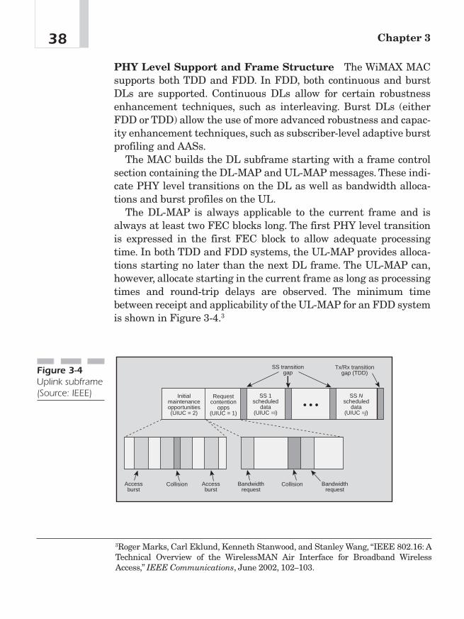
The DL-MAP is always applicable to the current frame and isalways at least two FEC blocks long. The first PHY level transitionis expressed in the first FEC block to allow adequate processingtime. In both TDD and FDD systems, the UL-MAP provides alloca-tions starting no later than the next DL frame. The UL-MAP can,however, allocate starting in the current frame as long as processingtimes and round-trip delays are observed. The minimum timebetween receipt and applicability of the UL-MAP for an FDD systemis shown in Figure 3-4.3
Chapter 338
3Roger Marks, Carl Eklund, Kenneth Stanwood, and Stanley Wang, “IEEE 802.16: ATechnical Overview of the WirelessMAN Air Interface for Broadband WirelessAccess,” IEEE Communications, June 2002, 102—103.
Initialmaintenanceopportunities(UIUC = 2)
Requestcontention
opps(UIUC = 1)
SS transitiongap
Tx/Rx transitiongap (TDD)
SS Nscheduled
data(UIUC =j)
SS 1scheduled
data(UIUC =i)
• • •
Accessburst
Accessburst
Collision CollisionBandwidthrequest
Bandwidthrequest
Figure 3-4Uplink subframe(Source: IEEE)

Transmission Convergence (TC)LayerBetween the PHY and MAC is a TC sublayer (see Figure 3-5). Thislayer transforms variable length MAC PDUs into fixed-length FECblocks (plus possibly a shortened block at the end of each burst). TheTC layer has a PDU sized to fit in the FEC block currently beingfilled. It starts with a pointer indicating where the next MAC PDUheader starts within the FEC block. This was shown in Figure 3-3.The TC PDU format allows resynchronization to the next MAC PDUin the event that the previous FEC block had irrecoverable errors.
39The Medium Access Control (MAC) Layer
MAC Layer
Transmission Convergence Layer
Physical Layer
Figure 3-5Relationship oftransmissionconvergencelayer withphysical andMAC layers(Source: IEEE)

This page intentionally left blank

How WiMAXWorks
CHAPTER 44
Copyright © 2005 by The McGraw-Hill Companies, Inc. Click here for terms of use.
Like most data communications, WiMAX relies on a process consist-ing of a session setup and authentication. The RLC manages andmonitors the quality of the service flow. With WiMAX, this process isa series of exchanges (DLs and ULs) between the BS and SS. A com-plex process determines what FDD and TDD settings will be used forthe service flow, FEC, sets encryption, bandwidth requests, burstprofiles, and so on. The process starts with channel acquisition bythe newly installed SS.
Channel AcquisitionThe MAC protocol includes an initialization procedure designed toeliminate the need for manual configuration. In other words, thesubscriber takes the SS out of the box, plugs in power and Ethernet,and connects almost immediately to the network. The followingparagraphs describe how that is possible without laborious usersetup or service provider truck roll.
Upon installation, the SS begins scanning its frequency list to findan operating channel. It may be preconfigured by the serviceprovider to register with a specified BS. This feature is useful indense deployments where the SS might hear a secondary BS due tospurious signals or when the SS picks up a sidelobe of a nearby BSantenna. Moreover, this feature will help service providers avoidexpensive installations and subsequent truck rolls.
After selecting a channel or channel pair, the SS synchronizes tothe DL transmission from the BS by detecting the periodic framepreambles. Once the PHY is synchronized, the SS will look for theperiodically broadcasted DCD and UCD messages that enable theSS to determine the modulation and FEC schemes used on the BS’scarrier.
Initial Ranging and Negotiation of SSCapabilities
Once the parameters for initial ranging transmissions are estab-lished, the SS will scan the UL-MAP messages present in every
Chapter 442
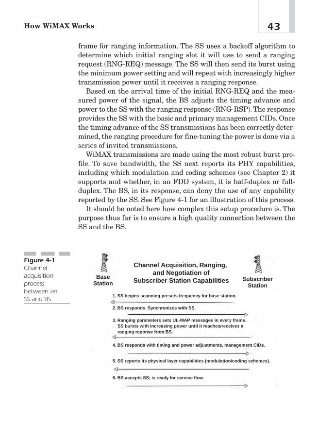
frame for ranging information. The SS uses a backoff algorithm todetermine which initial ranging slot it will use to send a rangingrequest (RNG-REQ) message. The SS will then send its burst usingthe minimum power setting and will repeat with increasingly highertransmission power until it receives a ranging response.
Based on the arrival time of the initial RNG-REQ and the mea-sured power of the signal, the BS adjusts the timing advance andpower to the SS with the ranging response (RNG-RSP).The responseprovides the SS with the basic and primary management CIDs. Oncethe timing advance of the SS transmissions has been correctly deter-mined, the ranging procedure for fine-tuning the power is done via aseries of invited transmissions.
WiMAX transmissions are made using the most robust burst pro-file. To save bandwidth, the SS next reports its PHY capabilities,including which modulation and coding schemes (see Chapter 2) itsupports and whether, in an FDD system, it is half-duplex or full-duplex. The BS, in its response, can deny the use of any capabilityreported by the SS. See Figure 4-1 for an illustration of this process.
It should be noted here how complex this setup procedure is. Thepurpose thus far is to ensure a high quality connection between theSS and the BS.
43How WiMAX Works
Channel Acquisition, Ranging, and Negotiation of
Subscriber Station CapabilitiesBase
StationSubscriber
Station
1. SS begins scanning presets frequency for base station.
2. BS responds. Synchronizes with SS.
3. Ranging parameters sets UL-MAP messages in every frame. SS bursts with increasing power until it reaches/receives a ranging reponse from BS.
4. BS responds with timing and power adjustments, management CIDs.
5. SS reports its physical layer capabilities (modulation/coding schemes).
6. BS accepts SS; is ready for service flow.
Figure 4-1Channelacquisitionprocessbetween an SS and BS
SS Authentication and Registration
Wi-Fi has been dogged with a reputation for lax security. Perhapsthe best “horror story” deals with a computer retailer who installeda wireless LAN. A customer purchased a Wi-Fi equipped laptop and,anxious to enjoy it, powered it up in the parking lot of the retailer.The new laptop owner was immediately able to tap into the retailer’sWi-Fi network and was able to capture some customer credit cardinformation. Fortunately, the new laptop owner was a journalist, nota con artist. The story, much to the chagrin of the national retailerand the Wi-Fi industry, made the national news. The Wi-Fi industryhas had to work hard to shake the reputation of having loose secu-rity measures. A similar story will not easily, if ever, occur withWiMAX.
Each SS contains both a manufacturer-issued factory-installedX.509 digital certificate and the certificate of the manufacturer. TheSS in the Authorization Request and Authentication Informationmessages sends these certificates, which set up the link between the48-bit MAC address of the SS and its public RSA key, to the BS. Thenetwork is able to verify the identity of the SS by checking the cer-tificates and can subsequently check the level of authorization of theSS. If the SS is authorized to join the network, the BS will respondto its request with an authorization reply containing an authoriza-tion key (AK) encrypted with the SS’s public key and used to securefurther transactions.
Upon successful authorization, the SS will register with the net-work. This will establish the secondary management connection ofthe SS and determine capabilities related to connection setup andMAC operation. The version of IP used on the secondary manage-ment connection is also determined during registration.
IP Connectivity
After registration, the SS attains an IP address via DHCP and estab-lishes the time of day via the Internet Time Protocol. The DHCPserver also provides the address of the TFTP server from which theSS can request a configuration file. This file provides a standard
Chapter 444

interface for providing vendor-specific configuration information. SeeFigure 4-2 for an illustration of this process.
Connection Setup
Now comes the connection setup, where data (the content) actuallyflows. WiMAX uses the concept of service flows to define one-waytransport of packets on either the DL or the UL. Service flows arecharacterized by a set of QoS parameters, such as those for latencyand jitter. To most efficiently utilize network resources, such asbandwidth and memory, WiMAX adopts a two-phase activationmodel in which resources assigned to a particular admitted serviceflow may not be actually committed until the service flow is acti-vated. Each admitted or active service flow is mapped to a MAC con-nection with a unique CID. In general, service flows in WiMAX arepreprovisioned, and the BS initiates the setup of the service flowsduring SS initialization.
In addition, the BS or the SS can dynamically establish serviceflows. The SS typically initiates service flows only if there is a
45How WiMAX Works
1. Authorization Request and Authentication Information (contains X.509 certificate)
2. BS responds with Authorization Reply (contains Authorization Key encrypted with the SS's public key).
3. With successful authorization, SS regusters with the network
4. After regustration, SS attains an IP address via DHCP.
5. SS DHCP server provides address of TFTP server where SS obtains a configuration file (interface for vendor-specific configuration info).
6. BS accepts SS; is ready for service flow.
Base Station
SubscriberStation
Subscriber Station Authentication and Registration
Figure 4-2SS authenticationand registration

dynamically signaled connection, such as a switched virtual connec-tion (SVC) from an ATM network. The establishment of service flowsis performed via a three-way handshaking protocol in which therequest for service flow establishment is responded to and theresponse acknowledged.
In addition to supporting dynamic service establishment, WiMAXsupports dynamic service changes in which service flow parametersare renegotiated. These service flow changes follow a three-wayhandshaking protocol similar to the one dynamic service flow estab-lishment uses.
Radio Link Control (RLC)RLC runs simultaneously to channel acquisition and service flow tomaintain a steady link. The WiMAX PHY requires equally advancedRLC, particularly the capability of the PHY to transition from oneburst profile to another. The RLC controls this capability as well asthe traditional RLC functions of power control and ranging.
RLC begins with periodic BS broadcast of the burst profiles thathave been chosen for the UP and DL. The particular burst profilesused on a channel are chosen based on a number of factors, such asrain region and equipment capabilities. Burst profiles for the DL areeach tagged with a Downlink Interval Usage Code (DIUC). Those forthe UL are each tagged with an UIUC.
During initial access, the SS performs initial power leveling andranging using RNG-REQ messages transmitted in initial mainte-nance windows. Adjustments to the SS’s transmit time advance andpower adjustments are returned to the SS in RNG-RSP messages.For ongoing ranging and power adjustments, the BS may transmitunsolicited RNG-RSP messages commanding the SS to adjust itspower or timing. This is shown in Figure 4-3.
During initial ranging, the SS also requests to be served in the DLvia a particular burst profile by transmitting its choice of DIUC tothe BS. The SS performs the choice before and during initial rangingbased on received DL signal quality measurements. The BS mayconfirm or reject the choice in the RNG-RSP. Similarly, the BS mon-itors the quality of the UL signal it receives from the SS. The BS
Chapter 446

commands the SS to use a particular UL burst profile simply byincluding the appropriate burst profile UIUC with the SS’s grants inUL-MAP messages.
After initially determining UP and DL burst profiles between theBS and a particular SS, RLC continues to monitor and control theburst profiles. Harsher environmental conditions, such as rain fades,can force the SS to request a more robust burst profile. Alternatively,exceptionally good weather may allow an SS to temporarily operatewith a more efficient burst profile. The RLC continues to adapt theSS’s current UL and DL burst profiles, always striving to achieve abalance between robustness and efficiency.
As the BS controls and directly monitors the UL signal quality, theprotocol for changing the UL burst profile for an SS is simple: the BSspecifies the profile’s UIUC whenever granting the SS bandwidth ina frame. This eliminates the need for an acknowledgment, as the SSwill always receive both the UIUC and the grant or neither. Thisnegates the possibility of UL burst profile mismatch between the BSand SS.
47How WiMAX Works
Radio Link Control
BaseStation
SubscriberStation
1. BS broadcasts burst profiles for uplink (UIUC) and downlink (DIUC).
2. SS does power leveling and ranging with range requests (RNG- REQ).
3. BS responds with range response (RNG- RSP).
4. SS transmits request for DIUC to BS.
5. BS confirms the choice in range response and commands SS to use a particular uplink burst profile UIUC in the UL- MAP message.
6. Radio Link Control continues to adapt the SS's current UL and DL burst profiles.
7. BS can grant downlink burst profile change request (DBPC- RSP).
Figure 4-3RLC ensuresongoing stabilityof the WiMAXconnection
In the DL, the SS monitors the quality of the receive signal andknows when to change its DL burst profile. The BS still has ultimatecontrol of the change. The SS has two available methods to requesta change in DL burst profile, depending on whether the SS operatesin the grant per connection (GPC) or grant per SS (GPSS) mode (see“Bandwidth Requests and Grants” in Chapter 5).
The first method would apply (based on the discretion of the BSscheduling algorithm) only to GPC SSs. In this case, the BS mayperiodically allocate a station maintenance interval to the SS. TheSS can use the RNG-REQ message to request a change in DL burstprofile. The preferred method is for the SS to transmit a DL burstprofile change request (DBPC-REQ). In this case, which is always anoption for GPSS SSs and can be an option for GPC SSs, the BSresponds with a DBPC-RSP message confirming or denying thechange.
Because messages may be lost due to irrecoverable bit errors, theprotocols for changing an SS’s DL burst profile must be carefullystructured. The order of the burst profile change actions is differentwhen transitioning to a more robust burst profile than when transi-tioning to a less robust one. The standard takes advantage of the factthat an SS is always required to listen to more robust portions of theDL as well as the profile that was negotiated.1
The ULEach connection in the UL direction is mapped to a scheduling ser-vice. Each scheduling service is associated with a set of rulesimposed on the BS scheduler responsible for allocating the ULcapacity and the request-grant protocol between the SS and the BS.The detailed specification of the rules and the scheduling serviceused for a particular UL connection are negotiated at connection
Chapter 448
1Roger Marks, Carl Eklund, Kenneth Stanwood, and Stanley Wang, “IEEE Standard802.16: A Technical Overview of the WirelessMAN Air Interface for Broadband Wire-less Access,” IEEE Communications, June 2002, 103—104.
setup time. The scheduling services in WiMAX are based on thosedefined for cable modems in the Data-Over-Cable Service InterfaceSpecification (DOCSIS) standard.2
Service FlowMinimizing customer intervention and truck roll is very importantfor WiMAX deployments. The Provisioned Service Flow Table, Ser-vice Class Table, and Classifier Rule Table are configured to supportself-installation and auto-configuration. When customers subscribeto the service, they tell the service provider the service flow infor-mation including the number of UL/DL connections with the datarates and QoS parameters, along with the types of applications (forexample, Internet, voice, or video) the customer intends to run. Theservice provider preprovisions the services by entering the serviceflow information into the service flow database. When the SS entersthe BS by completing the network entry and authentication proce-dure, the BS downloads the service flow information from the serviceflow database. Figure 4-4 provides an example of how the serviceflow information is populated. Figure 4-4A, 4-4B, and 4-4C indicatethat two SSs, identified by MAC address 0x123ab54 and 0x45fead1,have been preprovisioned. Each SS has two service flows, identifiedby sfIndex, with the associated QoS parameters that are identifiedby qosIndex 1 and 2, respectively. qosIndex points to a QoS entry inthe wmanIfBsServiceClassTable that contains three levels of QoS:Gold, Silver, and Bronze. sfIndex points to the entry in the wmanB-sClassifierRuleTable and indicates which rules shall be used to clas-sify packets on the given service flow.
When the SS with MAC address 0x123ab54 registers into the BS,the BS creates an entry in the wmanIfBaseRegisteredTable. Basedon the MAC address, the BS will be able to find the service flowinformation that has been preprovisioned. The BS will use adynamic service activate (DSA) message to create service flows for
49How WiMAX Works
2SCTE DSS 00-05, Data-Over-Cable Service Interface Specification (DOCSIS) SP-RFIv 1-105-000714, “Radio Frequency Interface 1.1 Specification,” July 2000.

sfIndex 100001 and 100002, with the preprovisioned service flowinformation. This can be seen in Figure 4-4. It creates two entries inwmanIfCmnCpsServiceFlowTable. The service flows will then beavailable for the customer to send data traffic.3
Chapter 450
3Govindan Nair, Joey Chou, Tomasz Madejski, Krzysztof Perycz, David Putzolu, andJerry Sydir, “IEEE 802.16 Medium Access Control and Service Provisioning,” IntelTechnology Journal 3, no. 3 (August 20, 2004).
D. wmanlfBsRegisteredSsTable
sfindex
ssindex
idindex
SSMA
Addr
QO
index
Direction
A. wmanlfBsProvisionedSfTable
B. wmanlfBsServiceClassTable
E. wmanlfCmnCpsServiceFlowTable C. wmanlfBsClassifierRuleTable
SSMACAddr
QOSindex
ServiceClass
MaxData
MaxLatency
sfindex
Src
Ad
r
Dest
lP
ddr
TOS
sfindex
sfCid
QOSindex
Use DSA Messagesto create serviceflows and entries
Figure 4-4Service flowprovisioning(Source: Intel)

ConclusionThis chapter explains the steps preceding the setup for the WiMAXservice flow. The process begins with ranging and negotiationbetween the BS and SS followed by authentication and registration.This design is noted for its robust nature. The WiMAX RLC thenestablishes the UL, which sets up the service flow. WiMAX basis inDOCSIS is evident in the sturdy design of this process.
51How WiMAX Works

This page intentionally left blank
Quality of Service (QoS)
on WiMAX
CHAPTER 55
Copyright © 2005 by The McGraw-Hill Companies, Inc. Click here for terms of use.
OverviewPerhaps networking cognoscenti’s greatest objection to broadbandwireless access systems is the notion that any data communicationsprotocol could function in a wireless environment. Networking is dif-ficult enough in a predictable, managed wired environment. Talkabout dropped packets! How can an IEEE 802 (Ethernet) variantfunction in free space? QoS refers, simply put, to reducing latency andjitter and avoiding dropping packets. This chapter alleviates thosefears by addressing both legacy- and WiMAX-specific fixes to ensurecarrier-grade performance in an otherwise hostile environment.
The ChallengeMechanisms in the WiMAX MAC provide for differentiated QoS tosupport the different needs of different applications. For instance,voice and video require low latency but tolerate some error rate. Incontrast, generic data applications cannot tolerate error, but latencyis not critical. The standard accommodates voice, video, and otherdata transmissions by using appropriate features in the MAC layer;this is more efficient than using these features in layers of controloverlaid on the MAC. In short, applying more bandwidth to the rightchannel at the right time reduces latency and improves QoS.
The WiMAX standard supports adaptive modulation, effectivelybalancing different data rates and link quality. The modulationmethod may be adjusted almost instantaneously for optimum datatransfer. WiMAX is able to dynamically shift modulations from 64-QAM to QPSK via 16-QAM, displaying its ability to overcome QoSissues with dynamic bandwidth allocation over the distance betweenthe BS and the SS.
Adaptive modulation allows efficient use of bandwidth and abroader customer base. The standard also supports both FDD andTDD. FDD, the legacy duplexing method, has been widely deployedin cellular telephony. It requires two channel pairs, one for trans-mission and one for reception, with some frequency separationbetween them to mitigate self-interference. A TDD system can
Chapter 554
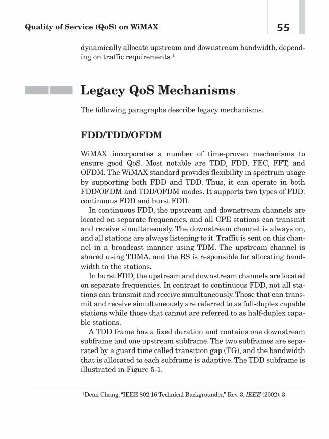
dynamically allocate upstream and downstream bandwidth, depend-ing on traffic requirements.1
Legacy QoS MechanismsThe following paragraphs describe legacy mechanisms.
FDD/TDD/OFDM
WiMAX incorporates a number of time-proven mechanisms toensure good QoS. Most notable are TDD, FDD, FEC, FFT, andOFDM. The WiMAX standard provides flexibility in spectrum usageby supporting both FDD and TDD. Thus, it can operate in bothFDD/OFDM and TDD/OFDM modes. It supports two types of FDD:continuous FDD and burst FDD.
In continuous FDD, the upstream and downstream channels arelocated on separate frequencies, and all CPE stations can transmitand receive simultaneously. The downstream channel is always on,and all stations are always listening to it.Traffic is sent on this chan-nel in a broadcast manner using TDM. The upstream channel isshared using TDMA, and the BS is responsible for allocating band-width to the stations.
In burst FDD, the upstream and downstream channels are locatedon separate frequencies. In contrast to continuous FDD, not all sta-tions can transmit and receive simultaneously. Those that can trans-mit and receive simultaneously are referred to as full-duplex capablestations while those that cannot are referred to as half-duplex capa-ble stations.
A TDD frame has a fixed duration and contains one downstreamsubframe and one upstream subframe. The two subframes are sepa-rated by a guard time called transition gap (TG), and the bandwidththat is allocated to each subframe is adaptive. The TDD subframe isillustrated in Figure 5-1.
55Quality of Service (QoS) on WiMAX
1Dean Chang, “IEEE 802.16 Technical Backgrounder,” Rev. 3, IEEE (2002): 3.
Within a TDD downlink subframe, transmissions coming from theBS are organized into different modulation and FEC groups. Thesubframe header, called the FCH, consists of a preamble field, a PHYcontrol field, and a MAC control field. The PHY control field is usedfor physical information, such as the slot boundaries, destined for allstations. It contains a map that defines where the physical slots forthe different modulation/FEC groups begin.
The groups are listed in ascending modulation order, with QPSKfirst, followed by 16-QAM and then 64-QAM. Each CPE stationreceives the entire DL frame, decodes the subframe, and looks forMAC headers indicating data for the station. The DL data is alwaysFEC coded. Payload data is encrypted, but message headers areunencrypted. The MAC control is used for MAC messages destinedfor multiple stations.
This variation uses burst single-carrier modulation with adaptiveburst profiling in which transmission parameters, including themodulation and coding schemes, may be adjusted individually toeach SS on a frame-by-frame basis. Channel bandwidths of 20 or 25MHz (typical United States allocation) or 28 MHz (typical Europeanallocation) are specified. Randomization is performed for spectralshaping and to ensure bit transitions for clock recovery.2
Forward Error Correction (FEC)
WiMAX utilizes FEC, a technique that doesn’t require the transmit-ter to retransmit any information that a receiver uses for correctingerrors incurred in transmission over a communication channel. Thetransmitter usually uses a common algorithm and embeds sufficientredundant information in the data block to allow the receiver to cor-
Chapter 556
Frame Header Downlink Subframe TG Uplink SubframeFigure 5-1TDD subframe(Source: IEEE)
2Roger Marks, Carl Eklund, Kenneth Stanwood, and Stanley Wang, “IEEE 802.16: ATechnical Overview of the WirelessMAN Air Interface for Broadband WirelessAccess,” IEEE Communications, June 2002, 98—107.
rect.Without FEC, error correction would require the retransmissionof whole blocks or frames of data, resulting in added latency and asubsequent decline in QoS.3
Need QoS? Throw more bandwidth at it!Throughput and latency are two essentials for network perfor-
mance. Taken together, these elements define the “speed” of a net-work.Whereas throughput is the quantity of data that can pass fromsource to destination in a specific time, round-trip latency is the timeit takes for a single data transaction to occur (the time betweenrequesting data and receiving it). Latency can also be thought of asthe time it takes from data send-off on one end to data retrieval onthe other (from one user to the other). Therefore, the better through-put (bandwidth) management, the better the QoS.4
Bandwidth Is the Answer—What Was theQuestion?
To ensure consistent QoS, WiMAX’s unique approach is to ensureconsistent bandwidth. How is that achieved?
Bandwidth Requests and Grants The WiMAX MAC accommo-dates two classes of SS that are differentiated by their ability toaccept bandwidth grants for a single connection or for the SS as awhole. Both classes of SS request bandwidth per connection to allowthe BS UL scheduling algorithm to properly consider QoS when allo-cating bandwidth. The two classes are GPC, where the BS grantsbandwidth explicitly to each station, and GPSS, where bandwidth isgranted to all connections belonging to the station.
The two classes of SS allow a trade-off between simplicity and effi-ciency. The need to explicitly grant extra bandwidth for RLC andrequests, coupled with the likelihood of more than one entry per SS,makes GPC less efficient and scalable than GPSS. Additionally, theability of the GPSS SS to react more quickly to the needs of the PHY
57Quality of Service (QoS) on WiMAX
3Ibid., 118—119.4“Low Latency—The Forgotten Piece of the Mobile Broadband Puzzle,” white paperfrom Flarion, February 2003, www.flarion.com.
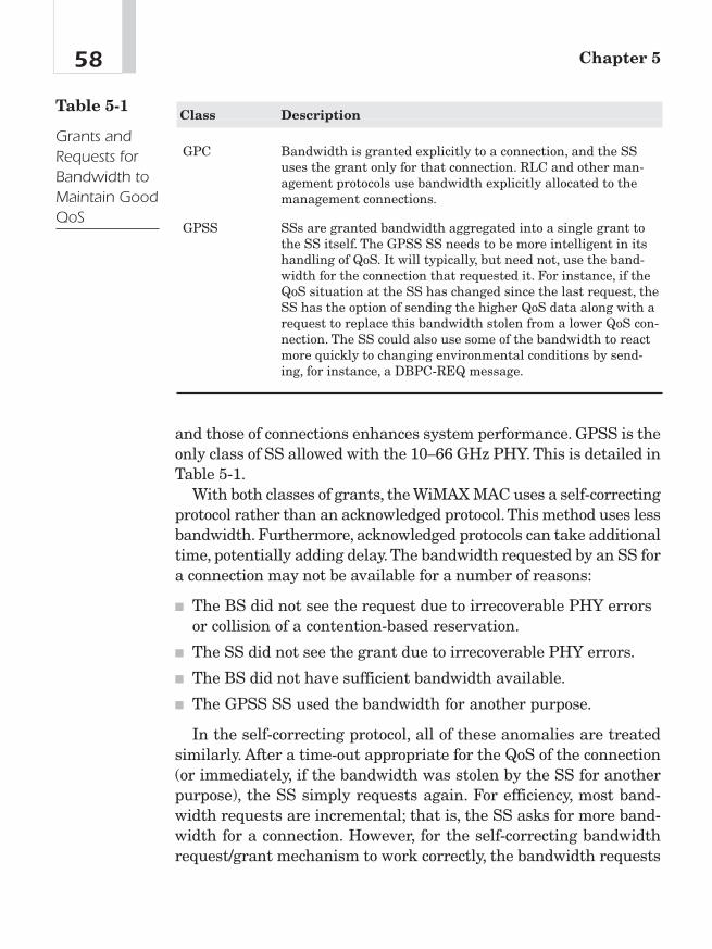
and those of connections enhances system performance. GPSS is theonly class of SS allowed with the 10—66 GHz PHY. This is detailed inTable 5-1.
With both classes of grants, the WiMAX MAC uses a self-correctingprotocol rather than an acknowledged protocol.This method uses lessbandwidth. Furthermore, acknowledged protocols can take additionaltime, potentially adding delay. The bandwidth requested by an SS fora connection may not be available for a number of reasons:
■ The BS did not see the request due to irrecoverable PHY errorsor collision of a contention-based reservation.
■ The SS did not see the grant due to irrecoverable PHY errors.
■ The BS did not have sufficient bandwidth available.
■ The GPSS SS used the bandwidth for another purpose.
In the self-correcting protocol, all of these anomalies are treatedsimilarly. After a time-out appropriate for the QoS of the connection(or immediately, if the bandwidth was stolen by the SS for anotherpurpose), the SS simply requests again. For efficiency, most band-width requests are incremental; that is, the SS asks for more band-width for a connection. However, for the self-correcting bandwidthrequest/grant mechanism to work correctly, the bandwidth requests
Chapter 558
Class Description
GPC Bandwidth is granted explicitly to a connection, and the SSuses the grant only for that connection. RLC and other man-agement protocols use bandwidth explicitly allocated to themanagement connections.
GPSS SSs are granted bandwidth aggregated into a single grant tothe SS itself. The GPSS SS needs to be more intelligent in itshandling of QoS. It will typically, but need not, use the band-width for the connection that requested it. For instance, if theQoS situation at the SS has changed since the last request, theSS has the option of sending the higher QoS data along with arequest to replace this bandwidth stolen from a lower QoS con-nection. The SS could also use some of the bandwidth to reactmore quickly to changing environmental conditions by send-ing, for instance, a DBPC-REQ message.
Table 5-1
Grants andRequests forBandwidth toMaintain GoodQoS

must occasionally be aggregate; that is, the SS informs the BS of itstotal current bandwidth needs for a connection.This allows the BS toreset its perception of the SS’s needs without a complicated protocolacknowledging the use of granted bandwidth.
The SS has many ways to request bandwidth, combining thedeterminism of unicast polling with the responsiveness of con-tention-based requests and the efficiency of unsolicited bandwidth.For continuous bandwidth demand, the SS need not request band-width; the BS grants it unsolicited. Bandwidth allocation and pollingmethods are detailed in Table 5-2.
To short-circuit the normal polling cycle, any SS with a connectionrunning UGS can use the poll-me bit in the grant management
59Quality of Service (QoS) on WiMAX
Term Description
Unicast polls Used for inactive stations and active stations that haveexplicitly requested to be polled. If an inactive station doesnot require bandwidth allocation, it responds to the poll byreturning a request for 0 bytes.
Multicast and Used to poll a group of inactive stations when there is broadcast polls insufficient bandwidth to poll the stations individually. A
CID identifies each active station, and certain CIDs arereserved for multicast and broadcast groups. When a multi-cast group is polled, the members of the group that requirebandwidth allocation respond to the poll. They use the con-tention resolution algorithm to resolve any conflicts thatarise from two or more stations transmitting at the sametime. If a station does not need bandwidth allocation, itdoes nothing; it is not allowed to respond with a bandwidthallocation of zero, as with the case of the individual poll.
Station Used by stations to request that the BS poll them to request initiated polls bandwidth allocation. Stations with active unsolicited grant
service connections typically use the poll. A station initiat-ing this type of poll sets a bit in the MAC header called thepoll-me bit, typically to request to be polled more frequentlyin order to satisfy the QoS of the connection. When the basestation receives the frame with the poll-me bit set, it pollsthe station individually.
Source: Ibe
Table 5-2
BandwidthAllocationPollingMethods

subheader to inform the BS that it needs to be polled for bandwidthneeds on another connection. The BS may choose to save bandwidthby polling SSs that have unsolicited grant services only when theyhave set the poll-me bit.
A more conventional way to request bandwidth is to send a band-width request MAC PDU that consists of simply the bandwidthrequest header and no payload. GPSS SSs can send this in any band-width allocation they receive. GPC terminals can send it in either arequest interval or a data grant interval allocated to their basic con-nection. A closely related method of requesting data is to use a grantmanagement subheader to piggyback a request for additional band-width for the same connection within a MAC PDU.5 These types ofservices are detailed in Table 5-3.
UGS is tailored for carrying services that generate fixed units ofdata periodically. Here the BS schedules regularly, in a preemptivemanner, grants of the size negotiated at connection setup without anexplicit request from the SS. This eliminates the overhead andlatency of bandwidth requests in order to meet the delay and delayjitter requirements of the underlying service. A practical limit on thedelay jitter is set by the frame duration. If more stringent jitterrequirements are to be met, output buffering is needed.
When used with UGS, the grant management subheader includesthe poll-me bit as well as the slip indicator flag, which allows the SSto report that the transmission queue is backlogged due to factorssuch as lost grants or clock skew between the WiMAX system andthe outside network.
The BS, upon detecting the slip indicator flag, can allocate someadditional bandwidth to the SS, allowing it to recover the normalqueue state. Connections configured with UGS are not allowed toutilize random access opportunities for requests.
The real-time polling service is designed to meet the needs of ser-vices that are dynamic in nature but offers periodic dedicatedrequest opportunities to meet real-time requirements. Because theSS issues explicit requests, the protocol overhead and latency is
Chapter 560
5Roger Marks, Carl Eklund, Kenneth Stanwood, and Stanley Wang, “IEEE 802.16: ATechnical Overview of the WirelessMAN Air Interface for Broadband WirelessAccess,” 103—104.
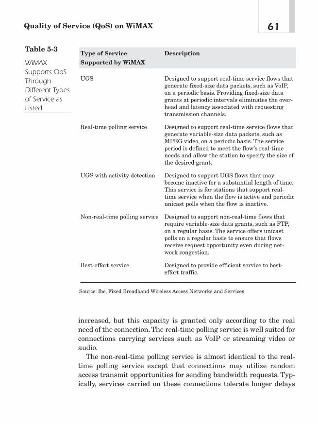
increased, but this capacity is granted only according to the realneed of the connection.The real-time polling service is well suited forconnections carrying services such as VoIP or streaming video oraudio.
The non-real-time polling service is almost identical to the real-time polling service except that connections may utilize randomaccess transmit opportunities for sending bandwidth requests. Typ-ically, services carried on these connections tolerate longer delays
61Quality of Service (QoS) on WiMAX
Type of Service Description
Supported by WiMAX
UGS Designed to support real-time service flows thatgenerate fixed-size data packets, such as VoIP,on a periodic basis. Providing fixed-size datagrants at periodic intervals eliminates the over-head and latency associated with requestingtransmission channels.
Real-time polling service Designed to support real-time service flows thatgenerate variable-size data packets, such asMPEG video, on a periodic basis. The serviceperiod is defined to meet the flow’s real-timeneeds and allow the station to specify the size ofthe desired grant.
UGS with activity detection Designed to support UGS flows that maybecome inactive for a substantial length of time.This service is for stations that support real-time service when the flow is active and periodicunicast polls when the flow is inactive.
Non-real-time polling service Designed to support non-real-time flows thatrequire variable-size data grants, such as FTP,on a regular basis. The service offers unicastpolls on a regular basis to ensure that flowsreceive request opportunity even during net-work congestion.
Best-effort service Designed to provide efficient service to best-effort traffic.
Source: Ibe, Fixed Broadband Wireless Access Networks and Services
Table 5-3
WiMAXSupports QoSThroughDifferent Typesof Service asListed
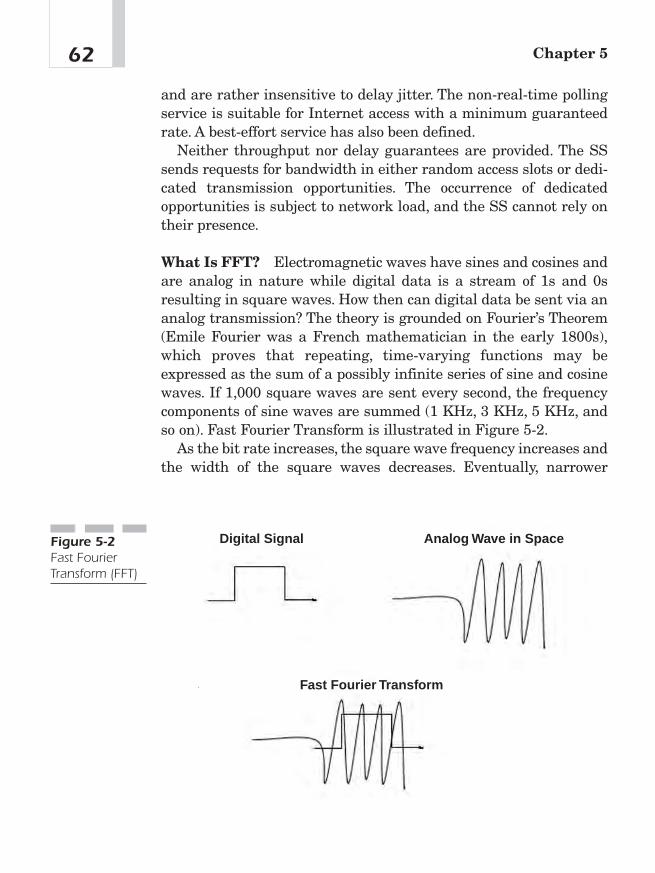
and are rather insensitive to delay jitter. The non-real-time pollingservice is suitable for Internet access with a minimum guaranteedrate. A best-effort service has also been defined.
Neither throughput nor delay guarantees are provided. The SSsends requests for bandwidth in either random access slots or dedi-cated transmission opportunities. The occurrence of dedicatedopportunities is subject to network load, and the SS cannot rely ontheir presence.
What Is FFT? Electromagnetic waves have sines and cosines andare analog in nature while digital data is a stream of 1s and 0sresulting in square waves. How then can digital data be sent via ananalog transmission? The theory is grounded on Fourier’s Theorem(Emile Fourier was a French mathematician in the early 1800s),which proves that repeating, time-varying functions may beexpressed as the sum of a possibly infinite series of sine and cosinewaves. If 1,000 square waves are sent every second, the frequencycomponents of sine waves are summed (1 KHz, 3 KHz, 5 KHz, andso on). Fast Fourier Transform is illustrated in Figure 5-2.
As the bit rate increases, the square wave frequency increases andthe width of the square waves decreases. Eventually, narrower
Chapter 562
Digital Signal Analog Wave in Space
Fast Fourier Transform
Figure 5-2Fast FourierTransform (FFT)
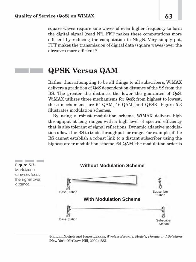
square waves require sine waves of even higher frequency to formthe digital signal (read N2). FFT makes these computations moreefficient by reducing the computation to NlogN. Very simply put,FFT makes the transmission of digital data (square waves) over theairwaves more efficient.6
QPSK Versus QAMRather than attempting to be all things to all subscribers, WiMAXdelivers a gradation of QoS dependent on distance of the SS from theBS: The greater the distance, the lower the guarantee of QoS.WiMAX utilizes three mechanisms for QoS; from highest to lowest,these mechanisms are 64-QAM, 16-QAM, and QPSK. Figure 5-3illustrates modulation schemes.
By using a robust modulation scheme, WiMAX delivers highthroughput at long ranges with a high level of spectral efficiencythat is also tolerant of signal reflections. Dynamic adaptive modula-tion allows the BS to trade throughput for range. For example, if theBS cannot establish a robust link to a distant subscriber using thehighest order modulation scheme, 64-QAM, the modulation order is
63Quality of Service (QoS) on WiMAX
6Randall Nichols and Panos Lekkas, Wireless Security: Models,Threats and Solutions(New York: McGraw-Hill, 2002), 283.
Without Modulation Scheme
With Modulation Scheme
Base Station
Base Station
SubscriberStation
SubscriberStation
Figure 5-3Modulationschemes focusthe signal overdistance.
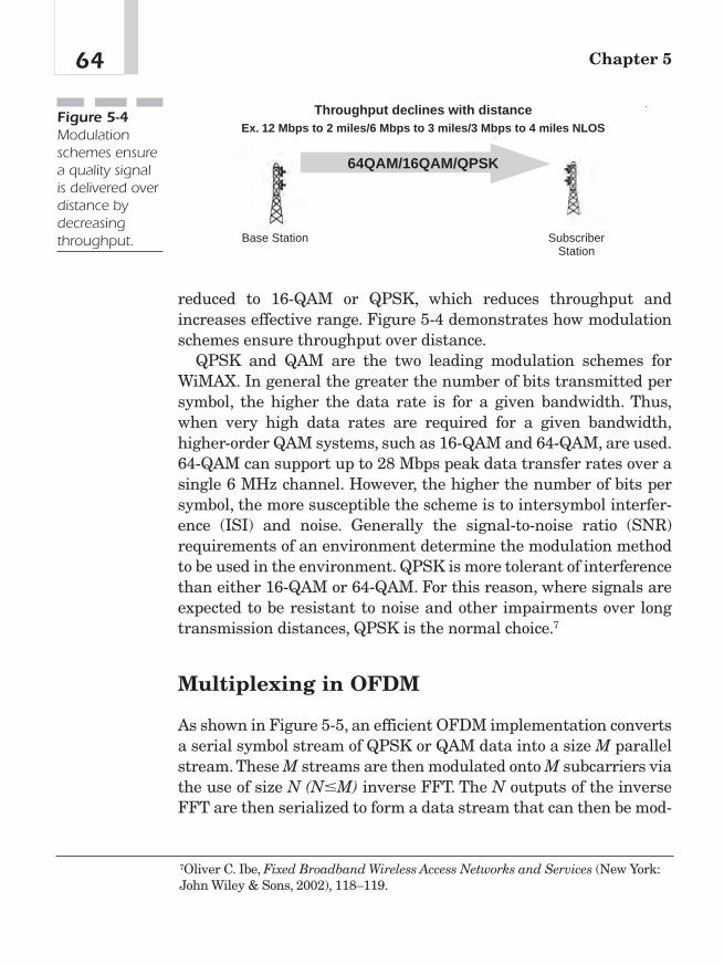
reduced to 16-QAM or QPSK, which reduces throughput andincreases effective range. Figure 5-4 demonstrates how modulationschemes ensure throughput over distance.
QPSK and QAM are the two leading modulation schemes forWiMAX. In general the greater the number of bits transmitted persymbol, the higher the data rate is for a given bandwidth. Thus,when very high data rates are required for a given bandwidth,higher-order QAM systems, such as 16-QAM and 64-QAM, are used.64-QAM can support up to 28 Mbps peak data transfer rates over asingle 6 MHz channel. However, the higher the number of bits persymbol, the more susceptible the scheme is to intersymbol interfer-ence (ISI) and noise. Generally the signal-to-noise ratio (SNR)requirements of an environment determine the modulation methodto be used in the environment. QPSK is more tolerant of interferencethan either 16-QAM or 64-QAM. For this reason, where signals areexpected to be resistant to noise and other impairments over longtransmission distances, QPSK is the normal choice.7
Multiplexing in OFDM
As shown in Figure 5-5, an efficient OFDM implementation convertsa serial symbol stream of QPSK or QAM data into a size M parallelstream. These M streams are then modulated onto M subcarriers viathe use of size N (N�M) inverse FFT. The N outputs of the inverseFFT are then serialized to form a data stream that can then be mod-
Chapter 564
Throughput declines with distanceEx. 12 Mbps to 2 miles/6 Mbps to 3 miles/3 Mbps to 4 miles NLOS
Base Station SubscriberStation
64QAM/16QAM/QPSK
Figure 5-4Modulationschemes ensurea quality signalis delivered overdistance bydecreasingthroughput.
7Oliver C. Ibe, Fixed Broadband Wireless Access Networks and Services (New York:John Wiley & Sons, 2002), 118–119.
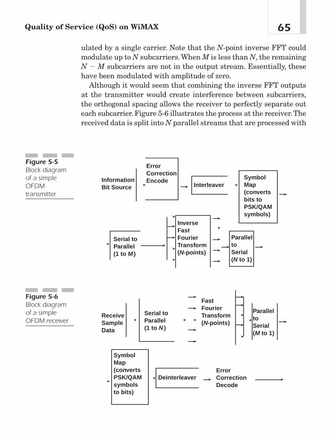
ulated by a single carrier. Note that the N-point inverse FFT couldmodulate up to N subcarriers. When M is less than N, the remainingN � M subcarriers are not in the output stream. Essentially, thesehave been modulated with amplitude of zero.
Although it would seem that combining the inverse FFT outputsat the transmitter would create interference between subcarriers,the orthogonal spacing allows the receiver to perfectly separate outeach subcarrier. Figure 5-6 illustrates the process at the receiver.Thereceived data is split into N parallel streams that are processed with
65Quality of Service (QoS) on WiMAX
InformationBit Source
ErrorCorrectionEncode
InterleaverSymbolMap(convertsbits toPSK/QAMsymbols)
Serial toParallel(1 to M )
InverseFastFourierTransform(N-points)
ParalleltoSerial(N to 1)
Figure 5-5Block diagramof a simpleOFDMtransmitter
Serial toParallel(1 to N )
ReceiveSampleData
SymbolMap(convertsPSK/QAMsymbolsto bits)
Deinterleaver
FastFourierTransform(N-points)
ParalleltoSerial(M to 1)
ErrorCorrectionDecode
Figure 5-6Block diagramof a simpleOFDM receiver
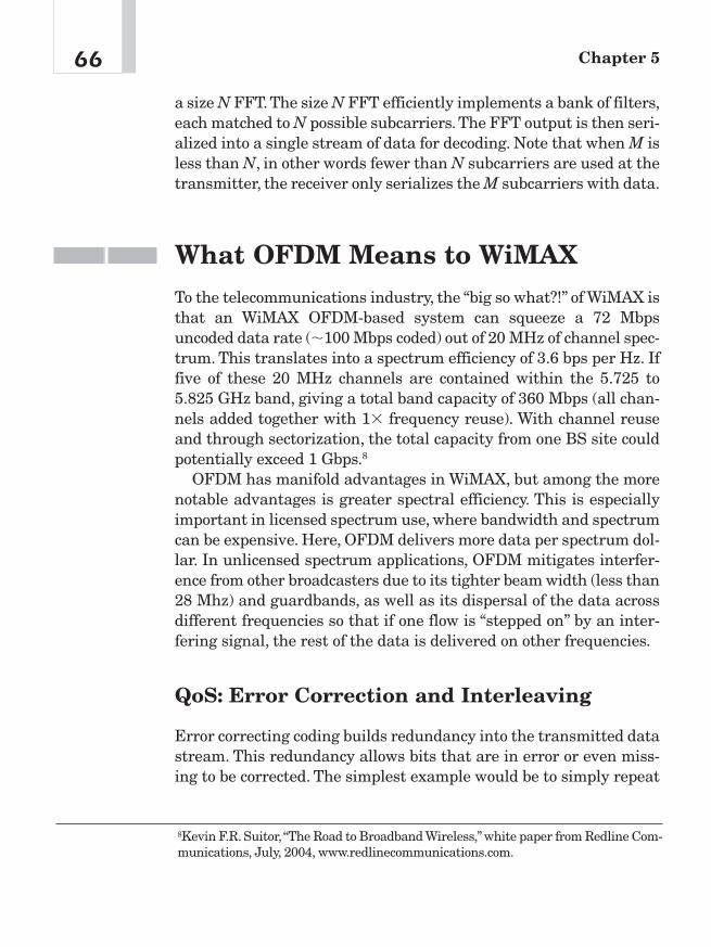
a size N FFT. The size N FFT efficiently implements a bank of filters,each matched to N possible subcarriers. The FFT output is then seri-alized into a single stream of data for decoding. Note that when M isless than N, in other words fewer than N subcarriers are used at thetransmitter, the receiver only serializes the M subcarriers with data.
What OFDM Means to WiMAXTo the telecommunications industry, the “big so what?!” of WiMAX isthat an WiMAX OFDM-based system can squeeze a 72 Mbpsuncoded data rate (�100 Mbps coded) out of 20 MHz of channel spec-trum. This translates into a spectrum efficiency of 3.6 bps per Hz. Iffive of these 20 MHz channels are contained within the 5.725 to5.825 GHz band, giving a total band capacity of 360 Mbps (all chan-nels added together with 1� frequency reuse). With channel reuseand through sectorization, the total capacity from one BS site couldpotentially exceed 1 Gbps.8
OFDM has manifold advantages in WiMAX, but among the morenotable advantages is greater spectral efficiency. This is especiallyimportant in licensed spectrum use, where bandwidth and spectrumcan be expensive. Here, OFDM delivers more data per spectrum dol-lar. In unlicensed spectrum applications, OFDM mitigates interfer-ence from other broadcasters due to its tighter beam width (less than28 Mhz) and guardbands, as well as its dispersal of the data acrossdifferent frequencies so that if one flow is “stepped on” by an inter-fering signal, the rest of the data is delivered on other frequencies.
QoS: Error Correction and Interleaving
Error correcting coding builds redundancy into the transmitted datastream. This redundancy allows bits that are in error or even miss-ing to be corrected. The simplest example would be to simply repeat
Chapter 566
8Kevin F.R. Suitor, “The Road to Broadband Wireless,” white paper from Redline Com-munications, July, 2004, www.redlinecommunications.com.
the information bits.This is known as a repetition code.Although therepetition code is simple in structure, more sophisticated forms ofredundancy are typically used because they can achieve a higherlevel of error correction. For OFDM, error correction coding meansthat a portion of each information bit is carried on a number of sub-carriers; thus, if any of these subcarriers has been weakened, theinformation bit can still arrive intact.
Interleaving is the other mechanism used in OFDM systems tocombat the increased error rate on the weakened subcarriers. Inter-leaving is a deterministic process that changes the order of trans-mitted bits. For OFDM systems, this means that bits that wereadjacent in time are transmitted on subcarriers that are spaced outin frequency. Thus errors generated on weakened subcarriers arespread out in time; that is, a few long bursts of errors are convertedinto many short bursts. Error correcting codes then correct theresulting short bursts of errors.
QoS Measures Specific to theWiMAX SpecificationWiMAX employs both legacy and next generation QoS measures.The following sections will focus on next generation QoS measurespeculiar to WiMAX.
Theory of Operation
WiMAX QoS mechanisms function in both UL and DL framesthrough the SS and the BS. The WiMAX specification for QoSinclude the following:
■ A configuration and registration function for preconfiguring SS-based QoS service flows and traffic parameters
■ A signaling function for dynamically establishing QoS-enabledservice flows and traffic parameters
67Quality of Service (QoS) on WiMAX

■ Utilization of MAC scheduling and QoS frame parameters forUL service flows
■ Utilization of QoS traffic parameters for DL service flows
■ Grouping of service flow properties into named service classes,so upper-Ayer entities and external applications (at both the SSand BS) may request service flows with desired QoS parametersin a globally consistent way
The principal mechanism for providing QoS is to associate packetstraversing the MAC interface into a service flow as identified by theCID. A service flow is a unidirectional flow of packets that is pro-vided a particular QoS (see Chapter 4). The SS and BS provide thisQoS, according to the QoS parameter set defined for the service flow.
The primary purpose of the QoS features defined here is to definetransmission ordering and scheduling on the air interface. However,these features often need to work in conjunction with mechanismsbeyond the air interface in order to provide end-to-end QoS or topolice the behavior of SSs.
Service flows in both the UL and DL direction may exist withoutactually being activated to carry traffic. All service flows have a 32-bit service flow ID (SFID); admitted and active flows also have a 16-bit CID.
Service Flows
A service flow is a MAC transport service that provides unidirec-tional transport of packets either to UL packets transmitted by theSS or to DL packets transmitted by the BS. A service flow is charac-terized by a set of QoS Parameters, such as latency, jitter, andthroughput assurances. In order to standardize operation betweenthe SS and BS, these attributes include details of how the SSrequests UL bandwidth allocations and how the BS UL scheduler isexpected to behave. The different elements of service flows employedby WiMAX are defined in Table 5-4. The three types of service flowsare listed in Table 5-5.
Chapter 568

69Quality of Service (QoS) on WiMAX
Element Description
SFID The principal identifier for the service flow inthe network. A service flow has at least an SFIDand an associated direction.
CID The mapping to an SFID that exists only whenthe connection has an admitted or active serviceflow.
ProvisionedQoSParamSet A QoS parameter set provisioned via means out-side of the scope of the standard, such as thenetwork management system.
AdmittedQoSParamSet A set of QoS parameters for which the BS (andpossibly the SS) is reserving resources. Theprincipal resource to be reserved is bandwidth.This set also includes an additional memory ortime-based resource required to subsequentlyactivate the flow.
ActiveQoSParamSet A set of QoS parameters defining the serviceactually being provided to the service flow. Onlyan active service flow may forward packets.
Authorization Module A logical function within the BS that approvesor denies every change to QoS Parameters andClassifiers associated with a service flow. Assuch, it defines an “envelope” that limits thepossible values of the AdmittedQoSParamSetand ActiveQoSParamSet.
Table 5-4
Elements ofthe ServiceFlow
Service Flow Description
Provisioned This service flow is known via provisioning by, for example,the network management system. Its AdmittedQoSParamSetand ActiveQoSParamSet are both null.
Admitted This service flow has resources reserved by the BS for itsAdmittedQoSParamSet, but these parameters are notactive. Some other mechanism has provisioned or may havesignaled admitted service flows.
Active This service flow has resources committed by the BS for itsActiveQoSParamSet. Its ActiveQoSParamSet is non-null.
Table 5-5
Types ofService Flows

The Object Model
The major objects of the architecture are represented by named rec-tangles, as illustrated in Figure 5-7. Each object has a number ofattributes; the attribute names that uniquely identify the object areunderlined. Optional attributes are denoted with brackets. The rela-tionship between the number of objects is marked at each end of theassociated line between the objects. For example, a service flow maybe associated with from 0 to N (many) PDUs, but a PDU is associ-ated with exactly one service flow. The service flow is the central con-cept of the MAC protocol. It is uniquely identified by a 32-big SFID.Service flows may be in either the UL or DL direction. Admitted andactive service flows are mapped to a 16-bit CID.
A CS process submits outgoing user data to the MAC SAP fortransmission on the MAC interface. The information delivered to theMAC SAP includes the CID identifying the connection across whichthe information is delivered. The service flow for the connection ismapped to MAC connection identified by the CID.
The service class is an optional object that may be implemented atthe BS. It is referenced by an ASCII name, which is intended for pro-
Chapter 570
MAC PDU SERVICE FLOW CONNECTION
SERVICE CLASSService Class NameQoS Parameter Set
SFIDCID
Payload
SFIDCID
ProvisionalQoSParamSetAdmittedQoSParamSet
ActiveQoSParamSet
Connection IDQoS Parameter Set
1NN
N
0,1
0,1
Figure 5-7Theory ofoperation object model(Source: IEEE)

visioning purposes. A service class is defined in the BS to have a par-ticular QoS parameter set. The QoS parameter sets of a service flowmay contain a reference to the service class name as a macro thatselects all of the QoS parameters of the service class. The service flowQoS parameter sets may augment and even override the QoS para-meter settings of the service class, subject to authorization by the BS.
Service Classes
The service class performs two functions. First, it allows operators toshift configuring service flows from the provisioning server to theBS. Operators provision the SSs with the service class name; fullimplementation of the name is configured at the BS. This allowsoperators to modify the implementation of a given service to local cir-cumstances without changing SS provisioning.
Second, it allows higher-layer protocols to create a service flow byits service class name. For example, telephony signaling may directthe SS to instantiate any available provisioned service flow of class“G.711.”
Any service flow may have its QoS parameter set specified in anyof three ways: first, by explicitly including all traffic parameters; sec-ond, by indirectly referring to a set of traffic parameters by specify-ing a service class name; and third, by specifying a service classname along with modifying parameters.
AuthorizationAn Authorization Module will approve every change to the serviceflow QoS parameters. This includes every DSA-REQ message tochange a QoS parameter set of an existing service flow. Such changescreate a new service flow, and every DSC-REQ message changes aQoS parameter set of an existing service flow. Such changes includerequesting an admission control decision (for example, setting theAdmittedQoSParamSet) and requesting activation of a service flow
71Quality of Service (QoS) on WiMAX
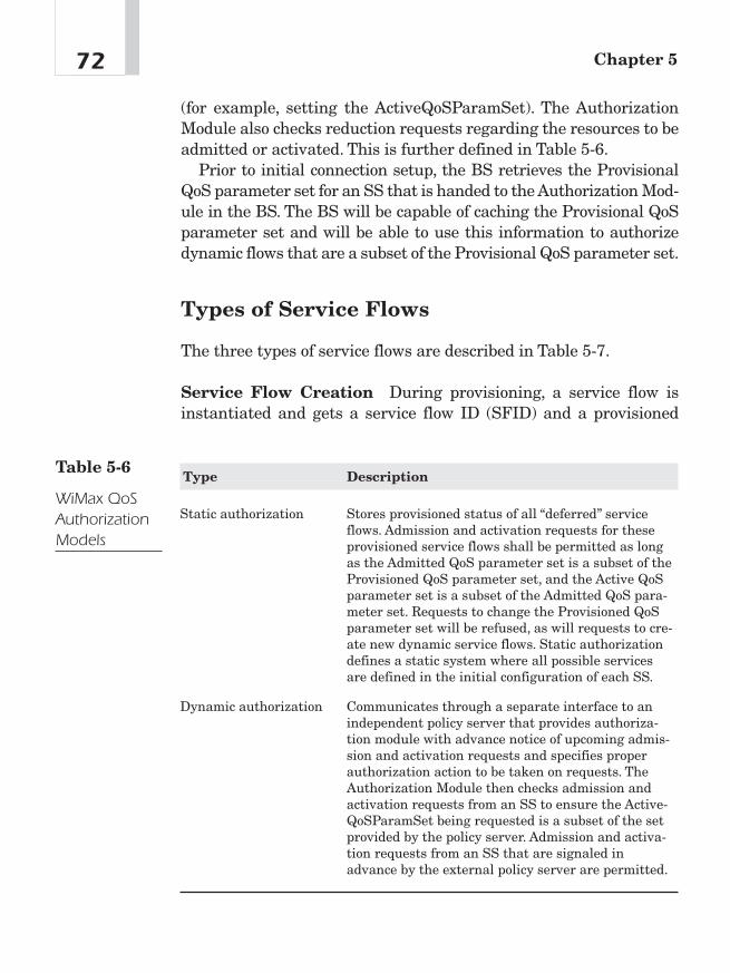
(for example, setting the ActiveQoSParamSet). The AuthorizationModule also checks reduction requests regarding the resources to beadmitted or activated. This is further defined in Table 5-6.
Prior to initial connection setup, the BS retrieves the ProvisionalQoS parameter set for an SS that is handed to the Authorization Mod-ule in the BS. The BS will be capable of caching the Provisional QoSparameter set and will be able to use this information to authorizedynamic flows that are a subset of the Provisional QoS parameter set.
Types of Service Flows
The three types of service flows are described in Table 5-7.
Service Flow Creation During provisioning, a service flow isinstantiated and gets a service flow ID (SFID) and a provisioned
Chapter 572
Type Description
Static authorization Stores provisioned status of all “deferred” serviceflows. Admission and activation requests for theseprovisioned service flows shall be permitted as longas the Admitted QoS parameter set is a subset of theProvisioned QoS parameter set, and the Active QoSparameter set is a subset of the Admitted QoS para-meter set. Requests to change the Provisioned QoSparameter set will be refused, as will requests to cre-ate new dynamic service flows. Static authorizationdefines a static system where all possible servicesare defined in the initial configuration of each SS.
Dynamic authorization Communicates through a separate interface to anindependent policy server that provides authoriza-tion module with advance notice of upcoming admis-sion and activation requests and specifies properauthorization action to be taken on requests. TheAuthorization Module then checks admission andactivation requests from an SS to ensure the Active-QoSParamSet being requested is a subset of the setprovided by the policy server. Admission and activa-tion requests from an SS that are signaled inadvance by the external policy server are permitted.
Table 5-6
WiMax QoSAuthorizationModels
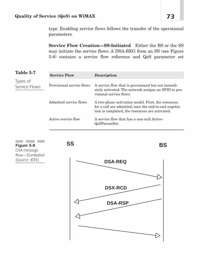
type. Enabling service flows follows the transfer of the operationalparameters.
Service Flow Creation—SS-Initiated Either the BS or the SSmay initiate the service flows. A DSA-REG from an SS (see Figure5-8) contains a service flow reference and QoS parameter set
73Quality of Service (QoS) on WiMAX
Service Flow Description
Provisional service flows A service flow that is provisioned but not immedi-ately activated. The network assigns an SFID to pro-visional service flows.
Admitted service flows A two-phase activation model. First, the resourcesfor a call are admitted; once the end-to-end negotia-tion is completed, the resources are activated.
Active service flow A service flow that has a non-null Active-QoSParamSet.
Table 5-7
Types ofService Flows
DSA-REQ
DSA-RSP
DSX-RCD
SS BSFigure 5-8DSA messageflow—SS-initiated(Source: IEEE)
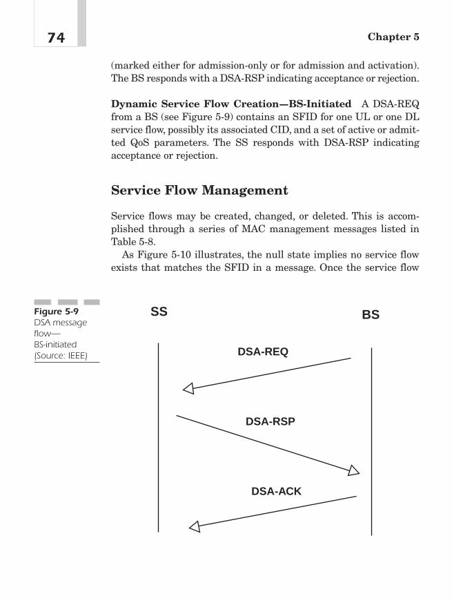
(marked either for admission-only or for admission and activation).The BS responds with a DSA-RSP indicating acceptance or rejection.
Dynamic Service Flow Creation—BS-Initiated A DSA-REQfrom a BS (see Figure 5-9) contains an SFID for one UL or one DLservice flow, possibly its associated CID, and a set of active or admit-ted QoS parameters. The SS responds with DSA-RSP indicatingacceptance or rejection.
Service Flow Management
Service flows may be created, changed, or deleted. This is accom-plished through a series of MAC management messages listed inTable 5-8.
As Figure 5-10 illustrates, the null state implies no service flowexists that matches the SFID in a message. Once the service flow
Chapter 574
DSA-REQ
DSA-RSP
DSA-ACK
SS BSFigure 5-9DSA messageflow—BS-initiated(Source: IEEE)

exists, it is operational and has an assigned SFID. In steady-stateoperation, a service flow resides in a nominal state.9
ConclusionService providers considering a WiMAX solution should take comfortin the many measures, both legacy- and WiMAX-specific, that focuson QoS issues. As the transmission is over free space, it is importantthat the QoS measures account for what is perhaps the most difficultof datacom environments. Legacy measures (such as TDD, FDD, andOFDM) uniquely address QoS issues for this protocol. Object modelsand dynamic service flows along with QoS parameters ensure goodQoS over the airwaves using WiMAX.
75Quality of Service (QoS) on WiMAX
9“802.16-2004 IEEE Standard for Local and Metropolitan Area Networks, Part 16, AirInterface for Fixed Broadband Wireless Access Systems,” June 24, 2004, 219—217.
Type Message Description
Dynamic Service Change (DSC) Changes existing service flow
Dynamic Service Delete (DSD) Deletes existing service flows
Dynamic Service Activate (DSA) Activates a service flow
Table 5-8
Service FlowMessages
DSD
DSA
DSC
OPERATIONALNULL
Figure 5-10Dynamic serviceflow overview(Source: IEEE)

This page intentionally left blank

Dealing withInterferencewith WiMAX
CHAPTER 66
Copyright © 2005 by The McGraw-Hill Companies, Inc. Click here for terms of use.
Interference—Some AssumptionsThe primary objection to wireless systems is the concern that thereare or will soon be too many operators on the same frequency, whichwill cause so much interference that the technology will becomeunusable. This issue is not that simple.
Such an assumption relies largely on the use of unlicensed spec-trum, where, according to Larry Lessig’s “tragedy of the commons”scenario,1 multiple operators broadcast on the same unlicensed (read“free”) spectrum, ultimately rendering it useless. Although this sce-nario may already be evident in the case of Wi-Fi variants (largelylimited to the 2.4 GHz range), WiMAX is considerably different.WiMAX currently has no problems, only solutions.
Since 1927, interference protection has always been at the core offederal regulators’ spectrum mission. The Radio Act of 1927 empow-ered the Federal Radio Commission to address interference con-cerns. This act primarily focused on three parameters: location,frequency, and power. The technology of the time did not permit con-sideration of a fourth element: time. In the modern sense, one mightconsider that a spectrum used by cell phones in a metropolitan area(dense population with millions of users) would command a veryhigh price at a spectrum auction. At the other end of the “spectrum,”a frequency band, say 2.5 GHz, in an exurban or rural market maygo for very little money at an auction or at resell by a spectrum bro-ker. It is entirely possible that the wireless service provider may finda very low cost licensed spectrum and enjoy a protected spectrum,which will largely negate the concern over interference from otherbroadcasters (the purpose of the Radio Act of 1927 in the first place).
Defining Interference or “ThinkReceiver”The Interference Protection Working Group of the FCC’s SpectrumPolicy Task Force recommends that the FCC should consider using
Chapter 678
1Larry Lessig, The Future of Ideas (San Francisco: Vintage Press), October 2002.

the “interference temperature” metric to quantify and manage inter-ference. “Interference temperature” is a measure of radio frequency(RF) power (power generated by other emitters and noise sources)available at a receiving antenna to be delivered to a receiver. Morespecifically, it is the temperature equivalent of the RF power avail-able at a receiving antenna per unit bandwidth, measured in units ofdegrees Kelvin. As conceptualized by the FCC, the terms “interfer-ence temperature” and “antenna temperature” are synonymous. Theterm “interference temperature” is more descriptive for interferencemanagement.
Interference temperature can be calculated as the power receivedby an antenna (watts) divided by the associated RF bandwidth(hertz) and a term known as Boltzman’s Constant (equal to 1.3807wattsec per ºKelvin). Alternatively, it can be calculated as the powerflux density available at a receiving antenna (watts per metersquared), multiplied by the effective capture area of the antenna(meter squared), with this quantity divided by the associated RFbandwidth (hertz) and Boltzman’s Constant. An “interference tem-perature density” can also be defined as the interference tempera-ture per unit area, expressed in units of ºKelvin per meter squaredand calculated as the interference temperature divided by the effec-tive capture area of the receiving antenna (determined by theantenna gain and the received frequency). Interference temperaturedensity can be measured for particular frequencies using a refer-ence antenna with known gain. Thereafter, it can be treated as a sig-nal propagation variable independent of receiving antennacharacteristics.
As illustrated in Figure 6-1, interference temperature measure-ments can be taken at receiver locations throughout the serviceareas of protected communications systems, thus estimating thereal-time conditions of the RF environment.2
Forms of Interference
Interference can be classified into two broad categories: co-channel(CoCh) interference (internal) and out-of-channel interference
79Dealing with Interference with WiMAX
2Michael Powell, “Broadband Migration—New Directions in Wireless Policy” (speechto Silicon Flatirons Conference, University of Colorado, Boulder, October 30, 2002).
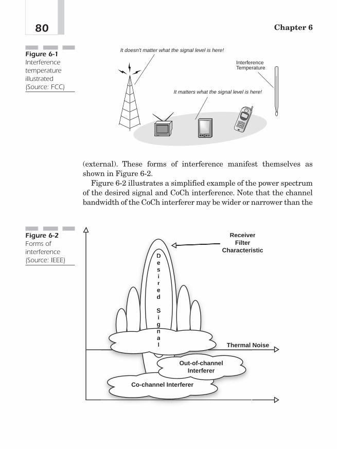
(external). These forms of interference manifest themselves asshown in Figure 6-2.
Figure 6-2 illustrates a simplified example of the power spectrumof the desired signal and CoCh interference. Note that the channelbandwidth of the CoCh interferer may be wider or narrower than the
Chapter 680
It doesn't matter what the signal level is here!
It matters what the signal level is here!
InterferenceTemperature
Figure 6-1Interferencetemperatureillustrated(Source: FCC)
NoiseThermal
Out-of-channelInterferer
Co-channel Interferer
ReceiverReceiveFilter
isticCharacteriDesired
Signal
Figure 6-2Forms ofinterference(Source: IEEE)
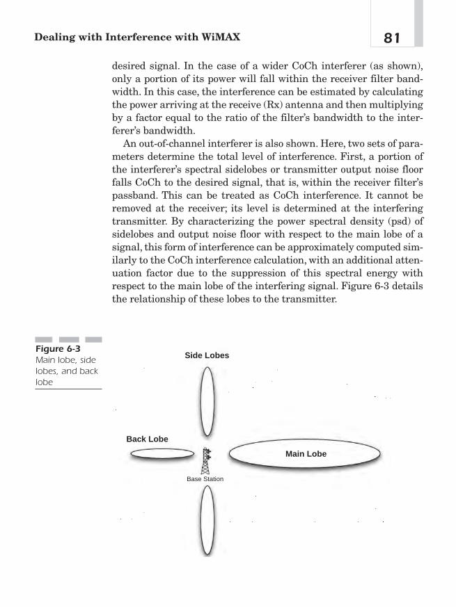
desired signal. In the case of a wider CoCh interferer (as shown),only a portion of its power will fall within the receiver filter band-width. In this case, the interference can be estimated by calculatingthe power arriving at the receive (Rx) antenna and then multiplyingby a factor equal to the ratio of the filter’s bandwidth to the inter-ferer’s bandwidth.
An out-of-channel interferer is also shown. Here, two sets of para-meters determine the total level of interference. First, a portion ofthe interferer’s spectral sidelobes or transmitter output noise floorfalls CoCh to the desired signal, that is, within the receiver filter’spassband. This can be treated as CoCh interference. It cannot beremoved at the receiver; its level is determined at the interferingtransmitter. By characterizing the power spectral density (psd) ofsidelobes and output noise floor with respect to the main lobe of asignal, this form of interference can be approximately computed sim-ilarly to the CoCh interference calculation, with an additional atten-uation factor due to the suppression of this spectral energy withrespect to the main lobe of the interfering signal. Figure 6-3 detailsthe relationship of these lobes to the transmitter.
81Dealing with Interference with WiMAX
Side Lobes
Back Lobe
Main Lobe
Base Station
Figure 6-3Main lobe, sidelobes, and backlobe
Second, the receiver filter of the victim receiver does not com-pletely suppress the main lobe of the interferer. No filter is ideal, andresidual power passing through the stopband of the filter can betreated as additive to the CoCh interference present. The perfor-mance of the victim receiver in rejecting out-of-channel signals,sometimes referred to as blocking performance, determines the levelof this form of interference. This form of interference can be simplyestimated in a manner similar to the CoCh interference calculation,with an additional attenuation factor due to the relative rejection ofthe filter’s stopband at the frequency of the interfering signal.
Cofrequency/Adjacent-Area Case Operators are encouraged toarrive at mutually acceptable sharing agreements that would allowfor the maximum provision of service by each licensee within its ser-vice area. Under the circumstances where a sharing agreementbetween operators does not exist or has not been concluded andwhere service areas are in close proximity, a coordination processshould be employed.3
Countering InterferenceFour parameters are brought under the control of network plannersto minimize external sources of interference:
■ Channel/band/frequency
■ Distance to the interference (farther is better)/distance tointended signal (closer is better)
■ Power levels (lower is better)
■ Antenna technology
Chapter 682
3IEEE 802.16.2-2004, “Coexistence of Fixed Broadband Wireless Access Systems,”March 17, 2004, 77—78.
Changing Channels Within the ISM or U-NIIBands
WiMAX’s specification calls for, depending on the variant, a fre-quency spread from 2—66 GHz (contrast with Wi-Fi’s, limited to 2.4GHz). Given that frequency spread, a for-profit service providerwould be wise to consider a low-cost licensed frequency and avoidaltogether the discussion of interference from other serviceproviders. The purpose of licensed frequency is to protect a broad-caster from other broadcasters interfering with his or her transmis-sion. (This is the original intent of the Radio Act of 1927.)
Recent changes in FCC policy now dictate that spectrum holdersmay resell their unused spectrum to other broadcasters, thus open-ing that spectrum to other operators. The FCC even hints at forcingthe resell of unused spectrum. See Chapter 10 for more informationon the regulatory aspects of WiMAX.
The specifications for industrial, scientific, and medical (ISM) andunlicensed national information infrastructure (U-NII) stipulatemultiple channels or frequencies. If interference is encountered onone frequency, the broadcaster can merely switch frequencies to achannel that is not being interfered with. ISM provides 11 overlap-ping channels (for North America): each channel is 22 MHz wide andis centered at 5 MHz intervals (beginning at 2.412 GHz and endingat 2.462 GHz). This means that only three channels (channels 1, 6,11) do NOT overlap. Table 6-1 indicates the channels of the unli-censed ISM band.
802.11a provides 12 channels: each channel is 20 MHz wide and iscentered at 20 MHz intervals (beginning at 5.180 GHz and ending at5.320 GHz for the upper and middle U-NII bands, beginning at 5.745GHz and ending at 5.805 GHz for the upper U-NII band). It is impor-tant to note that none of these channels overlap.4
83Dealing with Interference with WiMAX
4“A Comparison of 802.11a and 802.11b Wireless LAN Standards,” white paper fromLinksys, November 2004, www.linksys.com/products/images/wp_802.asp.
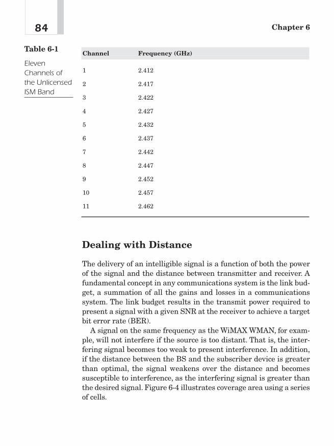
Dealing with Distance
The delivery of an intelligible signal is a function of both the powerof the signal and the distance between transmitter and receiver. Afundamental concept in any communications system is the link bud-get, a summation of all the gains and losses in a communicationssystem. The link budget results in the transmit power required topresent a signal with a given SNR at the receiver to achieve a targetbit error rate (BER).
A signal on the same frequency as the WiMAX WMAN, for exam-ple, will not interfere if the source is too distant. That is, the inter-fering signal becomes too weak to present interference. In addition,if the distance between the BS and the subscriber device is greaterthan optimal, the signal weakens over the distance and becomessusceptible to interference, as the interfering signal is greater thanthe desired signal. Figure 6-4 illustrates coverage area using a seriesof cells.
Chapter 684
Channel Frequency (GHz)
1 2.412
2 2.417
3 2.422
4 2.427
5 2.432
6 2.437
7 2.442
8 2.447
9 2.452
10 2.457
11 2.462
Table 6-1
ElevenChannels ofthe UnlicensedISM Band
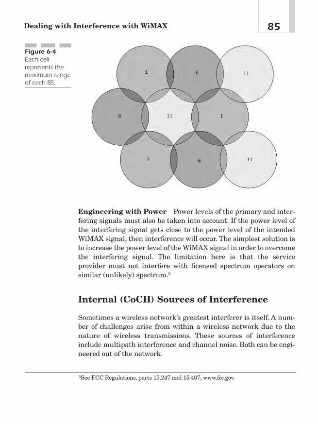
Engineering with Power Power levels of the primary and inter-fering signals must also be taken into account. If the power level ofthe interfering signal gets close to the power level of the intendedWiMAX signal, then interference will occur. The simplest solution isto increase the power level of the WiMAX signal in order to overcomethe interfering signal. The limitation here is that the serviceprovider must not interfere with licensed spectrum operators onsimilar (unlikely) spectrum.5
Internal (CoCH) Sources of Interference
Sometimes a wireless network’s greatest interferer is itself. A num-ber of challenges arise from within a wireless network due to thenature of wireless transmissions. These sources of interferenceinclude multipath interference and channel noise. Both can be engi-neered out of the network.
85Dealing with Interference with WiMAX
1
1
1
6
6
6
11
11
11
Figure 6-4Each cellrepresents themaximum rangeof each BS.
5See FCC Regulations, parts 15.247 and 15.407, www.fcc.gov.
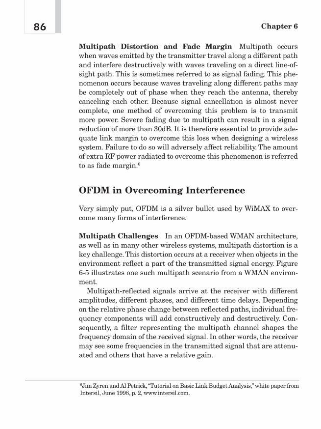
Multipath Distortion and Fade Margin Multipath occurswhen waves emitted by the transmitter travel along a different pathand interfere destructively with waves traveling on a direct line-of-sight path. This is sometimes referred to as signal fading. This phe-nomenon occurs because waves traveling along different paths maybe completely out of phase when they reach the antenna, therebycanceling each other. Because signal cancellation is almost nevercomplete, one method of overcoming this problem is to transmitmore power. Severe fading due to multipath can result in a signalreduction of more than 30dB. It is therefore essential to provide ade-quate link margin to overcome this loss when designing a wirelesssystem. Failure to do so will adversely affect reliability. The amountof extra RF power radiated to overcome this phenomenon is referredto as fade margin.6
OFDM in Overcoming Interference
Very simply put, OFDM is a silver bullet used by WiMAX to over-come many forms of interference.
Multipath Challenges In an OFDM-based WMAN architecture,as well as in many other wireless systems, multipath distortion is akey challenge.This distortion occurs at a receiver when objects in theenvironment reflect a part of the transmitted signal energy. Figure6-5 illustrates one such multipath scenario from a WMAN environ-ment.
Multipath-reflected signals arrive at the receiver with differentamplitudes, different phases, and different time delays. Dependingon the relative phase change between reflected paths, individual fre-quency components will add constructively and destructively. Con-sequently, a filter representing the multipath channel shapes thefrequency domain of the received signal. In other words, the receivermay see some frequencies in the transmitted signal that are attenu-ated and others that have a relative gain.
Chapter 686
6Jim Zyren and Al Petrick, “Tutorial on Basic Link Budget Analysis,” white paper fromIntersil, June 1998, p. 2, www.intersil.com.
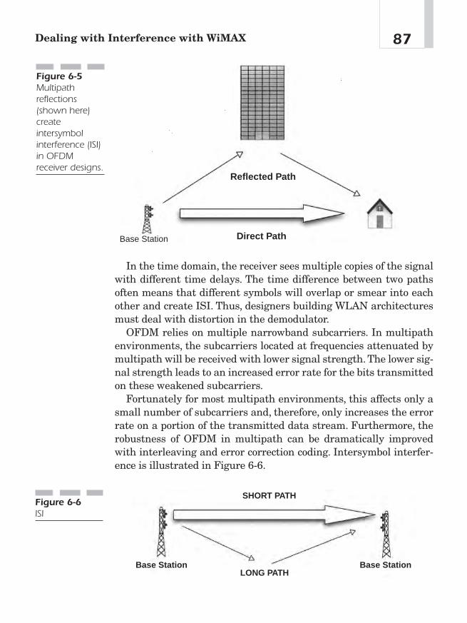
In the time domain, the receiver sees multiple copies of the signalwith different time delays. The time difference between two pathsoften means that different symbols will overlap or smear into eachother and create ISI. Thus, designers building WLAN architecturesmust deal with distortion in the demodulator.
OFDM relies on multiple narrowband subcarriers. In multipathenvironments, the subcarriers located at frequencies attenuated bymultipath will be received with lower signal strength. The lower sig-nal strength leads to an increased error rate for the bits transmittedon these weakened subcarriers.
Fortunately for most multipath environments, this affects only asmall number of subcarriers and, therefore, only increases the errorrate on a portion of the transmitted data stream. Furthermore, therobustness of OFDM in multipath can be dramatically improvedwith interleaving and error correction coding. Intersymbol interfer-ence is illustrated in Figure 6-6.
87Dealing with Interference with WiMAX
Reflected Path
Direct PathBase Station
Figure 6-5Multipathreflections(shown here)createintersymbolinterference (ISI)in OFDMreceiver designs.
SHORT PATH
LONG PATHBase Station Base Station
Figure 6-6ISI

Handling ISI
The time-domain counterpart of the multipath is ISI or smearing ofone symbol into the next. OFDM handles this type of multipath dis-tortion by adding a guard interval to each symbol. The guard inter-val is typically a cyclic or periodic extension of the basic OFDMsymbol. In other words, it looks like the rest of the symbol but con-veys no new information.
Because no new information is conveyed, the receiver can ignorethe guard interval and still be able to separate and decode the sub-carriers. When the guard interval is designed to be longer than anysmearing due to the multipath channel, the receiver is able to elim-inate ISI distortion by discarding the unneeded guard interval.Hence, ISI is removed with virtually no added receiver complexity.
It is important to note that discarding the guard interval doesimpact noise performance because the guard interval reduces theamount of energy available at the receiver for channel symbol decod-ing. In addition, it reduces the data rate, as no new information iscontained in the added guard interval. Thus a good system designwill make the guard interval as short as possible while maintainingsufficient multipath protection.
Why don’t single carrier (SC not OFDM) systems also use a guardinterval? Single carrier systems could remove ISI by adding a guardinterval between each symbol. However, this has a much moresevere impact on the data rate for single carrier systems than it doesfor OFDM. Because OFDM uses a bundle of narrowband subcarri-ers, it obtains high data rates with a relatively long symbol periodbecause the frequency width of the subcarrier is inversely propor-tional to the symbol duration. Consequently, adding a short guardinterval has little impact on the data rate.
Single carrier systems with bandwidths equivalent to OFDMmust use much shorter duration symbols. Hence, adding a guardinterval equal to the channel smearing has a much greater impacton data rate.7
Chapter 688
7Steven Halford and Karen Halford, “OFDM Uncovered: The Architecture,” whitepaper from CommsDesign, May 2, 2002, www.commsdesign.com/design_corner/OEG20020502S0013.
Mitigating Interference withAntenna TechnologyNew antenna technologies help reduce interference in WiMAX net-works.
Multiple Antennas: AAS
One method of mitigating the effects of multipath is antenna diver-sity. Because the cancellation of radio waves is geometry dependent,using two (or more) antennas separated by at least half of a wave-length can drastically mitigate this problem. On acquisition of a sig-nal, the receiver checks each antenna and simply selects the antennawith the best signal quality. This reduces but does not eliminate therequired link margin that would otherwise be needed for a systemthat does not employ diversity.
The downside is this approach requires more antennas and amore complicated receiver design. Another method of dealing withthe multipath problem is using an adaptive channel equalizer. Adap-tive equalization can be used with or without antenna diversity. Fig-ure 6-7 illustrates how adaptive antennas use beam forming toovercome interference.
WiMAX currently supports several multiple-antenna optionsincluding STC, MIMO antenna systems, and AAS. Table 6-2 illus-trates the advantages of using multiple-antenna over single antennatechnology.
A common scheme that exhibits both array gain and diversitygain is maximal ratio combining: this scheme combines multiplereceive paths to maximize SNR. Selection diversity, on the otherhand, primarily exhibits diversity gain. The signals are not com-bined; rather, the signal from the best antenna is chosen.
For AASs, multiple overlapped signals can be transmitted simul-taneously using SDMA, a technique that exploits the spatial dimen-sion to transmit multiple beams that are spatially separated. SDMAmakes use of CCIR, diversity gain, and array gain.
89Dealing with Interference with WiMAX

The higher performance and lower interference capabilities ofMIMO and AAS make them attractive over other high-rate tech-niques for WiMAX systems in costly, licensed bands. A key advan-
Chapter 690
Base Station
Figure 6-7Adaptiveantennas usebeam formingto avoidinterference.
Type Antenna Description
Array gain Gain achieved by using multiple antennas sothat the signal adds coherently.
Diversity gain Gain achieved by utilizing multiple paths sothat a single bad path does not limit perfor-mance. Effectively, diversity gain refers totechniques at the transmitter or receiver toachieve multiple looks at the fading channel.These schemes improve performance byincreasing the stability of the received signalstrength in the presence of wireless signalfading. Diversity may be exploited in the spa-tial (antenna), temporal (time), or spectral(frequency) dimensions.
Co-channel Interference Rejection of signals by using the different Rejection (CCIR) channel response of the interferers.
Table 6-2
Advantages ofUsing Multiple-AntennaTechnologyOver SingleAntennaTechnology

tage of transmit diversity is that it can be implemented at the BS,which can absorb higher costs of multiple antennas and associatedRF chains. This shifts cost away from the SS, which enables fastermarket penetration of WiMAX products.8
Adaptive Antenna (AA) Techniques
AA directly affects coexistence because the RF energy radiated bytransmitters is focused in specific areas of the cell, not radiated in alldirections. Moreover, beam forming, with the goal of maximizing thelink margin for any given user inside the cell coverage area at anygiven time, makes the AA beams’ azimuth and elevation vary fromtime to time. Figure 6-8 explains interference vis-à-vis non-AAS cells.
91Dealing with Interference with WiMAX
8Atul Salvekar, Sumeet Sandhu, Qinghua Li, Minh-Anh Vuong, and Xiashu Qian,“Multiple Antenna Technology in WiMAX Systems,” Intel Technology Journal 8, no. 3(August 20, 2004), http://developer.intel.com/technology/itj/2004/volume08issue03/art05_multiantenna/p01_abstract.htm.
Out-of-Cell Interference
Non-Adaptive Array System Cell
Base Station
Figure 6-8Non-AAS cell
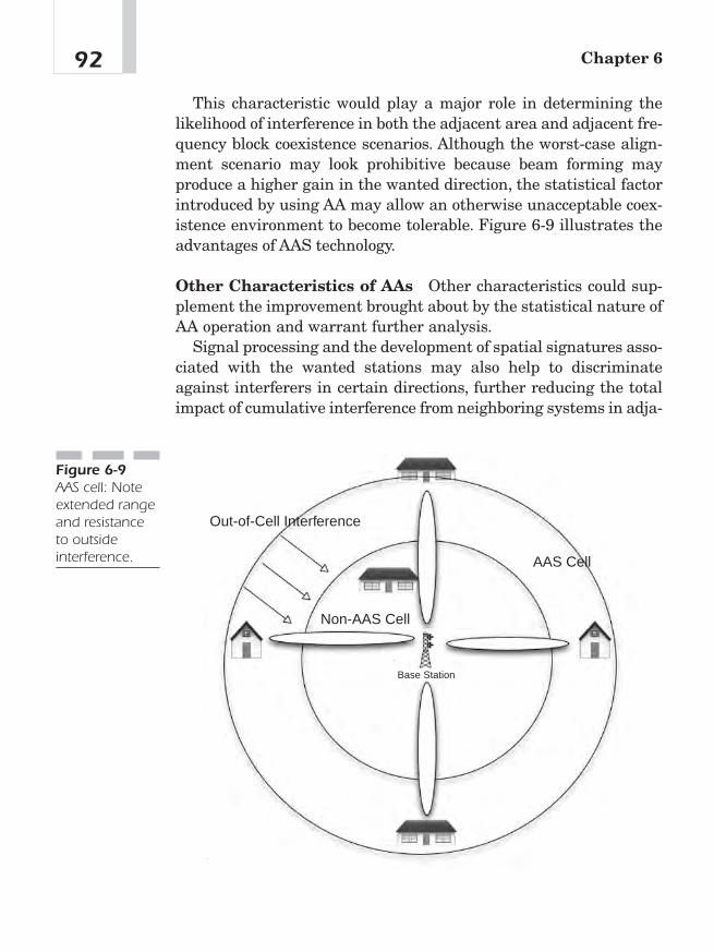
This characteristic would play a major role in determining thelikelihood of interference in both the adjacent area and adjacent fre-quency block coexistence scenarios. Although the worst-case align-ment scenario may look prohibitive because beam forming mayproduce a higher gain in the wanted direction, the statistical factorintroduced by using AA may allow an otherwise unacceptable coex-istence environment to become tolerable. Figure 6-9 illustrates theadvantages of AAS technology.
Other Characteristics of AAs Other characteristics could sup-plement the improvement brought about by the statistical nature ofAA operation and warrant further analysis.
Signal processing and the development of spatial signatures asso-ciated with the wanted stations may also help to discriminateagainst interferers in certain directions, further reducing the totalimpact of cumulative interference from neighboring systems in adja-
Chapter 692
Out-of-Cell Interference
AAS Cell
Non-AAS Cell
Base Station
Figure 6-9AAS cell: Noteextended rangeand resistanceto outsideinterference.
cent areas. For systems operating in adjacent frequencies, the loss ofcoherency in out-of-band operations reduces the AA gain toward theinterferers/victims, which could reduce the amount of interferencepower.9
Dynamic Frequency Selection(DFS)The WiMAX specification calls for a mechanism called DFS for usein unlicensed frequencies. This mechanism simply has the serviceflow shift to a different frequency if activity is detected on a primaryfrequency.
If You Want Interference, Call the BlackRavens
One of the author’s first real jobs was intelligence officer, TacticalElectronic Warfare Squadron 135 (abbreviated VAQ-135 with thenickname “World Famous Black Ravens”) of the United States Navy.This squadron flew the EA-6B tactical jamming aircraft. The air-plane is equipped with ALQ-99 jamming system and is used tacti-cally to jam enemy radar and radio communications. It has beenrumored for many years that the squadron’s four aircraft, strategi-cally positioned, could shut down most of the electromagnetic spec-trum of the United States (TV, radio, and so on). Figure 6-10 is aphoto of the officers and men of VAQ-135 with the EA-6B in thebackground.
In a strategic role during the Cold War, the United States AirForce developed the B-52G, a bomber equipped with an extensivesuite of electronic jamming equipment designed to defeat the Soviet
93Dealing with Interference with WiMAX
9“802.16.2™ IEEE Recommended Practice for Local and Metropolitan Area Net-works Coexistence of Fixed Broadband Wireless Access Systems,” IEEE (March2004): 86—87.

air defenses. This would require overwhelming air defenseoverlapping radar networks that operated at a variety of frequen-cies. It would also deliver overwhelming interference on air defenseradio communications, making the airwaves unusable for the Sovi-ets. By shutting down Soviet air defense radars and negating theirability to communicate by radio, the B-52G would clear a path foritself and other strategic bombers to targets for destruction bynuclear attack. A trivia question on student examinations at theUnited States Navy’s Electronic Warfare School in the 1980s was“What is the electromagnetic coverage of the B-52G jamming sys-tem?” The correct answer was “DC (Direct Current) to Daylight.”
Chapter 694
Figure 6-10EA-6B tacticaljamming aircraftof the UnitedStates Navy, the“World FamousBlack Ravens.”Author Ohrtmanis first on left,standing.
Security and802.16 WiMAX
CHAPTER 77
Copyright © 2005 by The McGraw-Hill Companies, Inc. Click here for terms of use.

Security in WiMAX NetworksA major objection service providers have toward broadband wirelessaccess networks is security. Will the wireless protocol provide ade-quate security to prevent theft of service, thus protecting theirinvestment in the wireless infrastructure? Will the privacy of theirsubscribers be protected from hackers who might ultimately perpe-trate identity theft? The WiMAX specification offers some very pow-erful security measures, making casual theft of service impossible.WiMAX subscribers need not fear for their privacy while utilizingthis wireless service.
The Security Sublayer
The WiMAX specification includes a security sublayer that providessubscribers with privacy across the fixed broadband wireless net-work. It does this by encrypting connections between the SS and BS.In addition, the security sublayer provides operators with strongprotection against theft of service. The BS protects against unautho-rized access to this data transport service by enforcing encryption ofthe associated service flows across the network.The privacy sublayeremploys an authenticated client/server key management protocol inwhich the BS, the server, controls distribution of keying material toits client SSs. Additionally, adding digital certificate-based SSauthentication to its key management protocol strengthens the basicprivacy mechanisms. Figure 7-1 illustrates the relationship of theMAC privacy layer with the MAC and physical layers.
Security Architecture in WiMAX Privacy in the WiMAX speci-fication has two component protocols:
■ An encapsulation protocol for encrypting packet data across thefixed broadband wireless access (BWA) network. This protocoldefines first a set of supported cryptographic suites (pairings ofdata encryption and authentication of algorithms and rules forapplying those algorithms to a MAC PDU payload).
Chapter 796
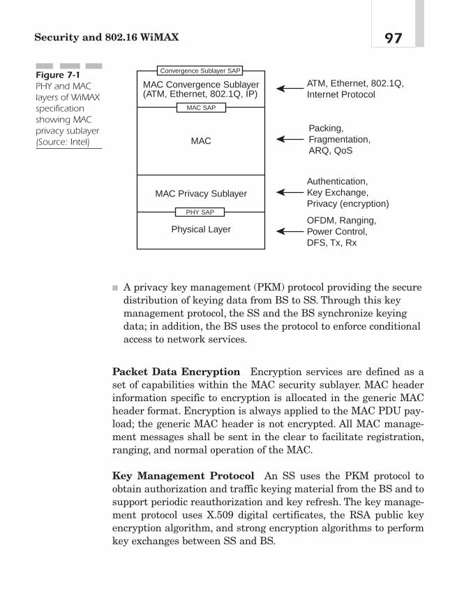
■ A privacy key management (PKM) protocol providing the securedistribution of keying data from BS to SS. Through this keymanagement protocol, the SS and the BS synchronize keyingdata; in addition, the BS uses the protocol to enforce conditionalaccess to network services.
Packet Data Encryption Encryption services are defined as aset of capabilities within the MAC security sublayer. MAC headerinformation specific to encryption is allocated in the generic MACheader format. Encryption is always applied to the MAC PDU pay-load; the generic MAC header is not encrypted. All MAC manage-ment messages shall be sent in the clear to facilitate registration,ranging, and normal operation of the MAC.
Key Management Protocol An SS uses the PKM protocol toobtain authorization and traffic keying material from the BS and tosupport periodic reauthorization and key refresh. The key manage-ment protocol uses X.509 digital certificates, the RSA public keyencryption algorithm, and strong encryption algorithms to performkey exchanges between SS and BS.
97Security and 802.16 WiMAX
MAC
MAC Convergence Sublayer(ATM, Ethernet, 802.1Q, IP)
MAC Privacy Sublayer
Physical Layer
ATM, Ethernet, 802.1Q,Internet Protocol
Packing,Fragmentation,ARQ, QoS
Authentication,Key Exchange,Privacy (encryption)
OFDM, Ranging,Power Control, DFS, Tx, Rx
Convergence Sublayer SAP
MAC SAP
PHY SAP
Figure 7-1PHY and MAClayers of WiMAXspecificationshowing MACprivacy sublayer(Source: Intel)

The PKM protocol adheres to a client/server model where the SS(a PKM client) requests keying material, and the BS (a PKM server)responds to those requests. This protocol ensures that individual SSclients receive only keying material for which they are authorized.The PKM protocol uses MAC management messaging: PKM-REQand PKM-RSP.
The PKM protocol uses public key cryptography to establish ashared, secret AK between the SS and the BS. The shared, secret keyis then used to secure subsequent PKM exchanges of traffic encryp-tion keys (TEKs). This two-tiered mechanism for key distributionpermits refreshing of TEKs without incurring the overhead of com-putation-intensive public-key operations.
A BS authenticates a client SS during the initial authorizationexchange. Each SS carries a unique X.509 digital certificate issuedby the manufacturer. The digital certificate contains the SS’s publickey and MAC address. When requesting an AK, an SS presents itsdigital certificate to the BS.The BS verifies the digital certificate andthen uses the verified public key to encrypt an AK that the BS thensends back to the requesting SS. Figure 7-2 details the relationshipbetween X.509 and 56-bit DES.
The BS associates an SS’s authentication identity with a payingsubscriber and hence with the data service (voice, video, data) thatsubscriber is authorized to access. Thus, with the AK exchange, theBS establishes an authenticated identity of a client SS and the ser-vices the SS is authorized to access.
Chapter 798
Authentication with X.509 encryption
Data flow via 56-bit DES
Base Station
Base Station
SubscriberStation
SubscriberStation
Figure 7-2WiMAX security:X.509encryption and56-bit DES
Because the BS authenticates the SS, it can protect against anattacker employing a cloned SS that is masquerading as a legitimateSS. The use of the X.509 certificates prevents cloned SSs fromassigning fake credentials to a BS.
All SSs have factory-installed RSA private/public key pairs or pro-vide an internal algorithm to generate such key pairs dynamically. Ifan SS relies on an internal algorithm to generate its RSA key pair,the SS shall generate the key pair prior to its first AK exchange. AllSSs that rely on internal algorithms to generate an RSA key pairshall support a mechanism for installing a manufacturer-issuedX.509 certificate following key generation.
The use of a factory-installed RSA private/public key pair limitsthe odds of success for any would-be hackers. The first hurdle for awould-be hacker is to have an SS from the same vendor as the tar-geted BS, and the second is to crack the X.509 encryption.1
In RSA, a message is encrypted with a public key and can only bedecrypted with the corresponding private key. Any station canencrypt a message with the public key, but only one station candecrypt one using the secret private key. The flow of the encryptionis many to one.
The reverse is also true: A message can be encrypted with a pri-vate key and can only be decrypted with the corresponding publickey. This sort of inside-out encryption, to give it a name, might seemsilly because anybody can use the public key to read the message.The flow of the encryption is one to many. Inside-out encryption pro-vides no security, but the symmetry also holds, as the public key canonly decrypt messages encrypted with the secret private key.2
Security Associations (SAs) An SA is the set of security infor-mation a BS and one or more of its client SSs share in order to sup-port secure communications across the WiMAX standard. Three
99Security and 802.16 WiMAX
1“802.16-2004 IEEE Standard for Local and Metropolitan Area Networks, Part 16, AirInterface for Fixed Broadband Wireless Access Systems,” June 24, 2004, 271.2Greg Goebel, 11.1 “Message Authentication & Digital Signatures” in Codes, Ciphers& Codebreaking, v.2.2.0, June 1, 2004, www.vectorsite.net/ttcodeb.html. p.1 section11.1.
types of SAs are defined: Primary, Static, and Dynamic. Each man-ageable SS establishes a Primary Security association during the SSinitialization process. Static SAs are provisioned within the BS.Dynamic SAs are established and eliminated on the fly in responseto the initiation and termination of specific service flows. Both Sta-tic and Dynamic SAs can be shared by multiple SSs.
An SA’s keying material has a limited lifetime. When the BS deliv-ers SA keying material to an SS, it also provides the SS with thatmaterial’s remaining lifetime. The SS is responsible for requestingnew keying material from the BS before the set of keying materialthat the SS currently holds expires at the BS. Should the currentkeying material expire before a new set of keying material isreceived, the SS will perform network entry. The PKM protocol spec-ifies how the SS and BS maintain key synchronizations.
The PKM Protocol
WiMAX utilizes PKM to establish a secure link between the basestation and the subscriber station. The following paragraphs willdescribe this in greater detail.
SS Authorization and AK Exchange Overview The SS autho-rization process includes the following steps:
■ The BS authenticates a client SS’s identity.
■ The BS provides the authenticated SS with an AK from which akey encryption key (KEK) and message authentication keys arederived.
■ The BS provides the authenticated SS with the identities andproperties of primary and static SAs from which the SS isauthorized to obtain keying information.
After achieving initial authorization, an SS periodically seeksreauthorization with the BS; reauthorization is also managed by theSS’s authorization state machine. An SS must maintain its autho-rization status with the BS in order to be able to refresh aging TEKs.
Chapter 7100

An SS begins authorization by sending an Authentication Infor-mation message to its BS. The Authentication Information messagecontains the SS manufacturer’s X.509 certificate, issued by the man-ufacturer itself or by an external authority.
The SS sends an Authorization Request message to its BS imme-diately after sending the Authentication Information message. Thisis a request for an AK, as well as for the Security Association Identi-fications (SAIDs) identifying any Static Security SAs the SS isauthorized to participate in. The Authorization Request messageincludes the following:
■ A manufacturer-issued X.509 certificate
■ A description of the cryptographic algorithms the requesting SSsupports; an SS’s cryptographic capabilities are presented to theBS as a list of cryptographic suite identifiers, each indicating aparticular pairing of packet data encryption and packet dataauthentication algorithms the SS supports
■ The SS’s Basic CID
In response to an Authorization Request message, a BS validatesthe requesting SS’s identity, determines the encryption algorithmand protocol support it shares with the SS, activates an AK for theSS, encrypts it with the SS’s public key, and sends it back to the SSin an Authorization Reply message.The authorization reply includesthe following:
■ An AK encrypted with the SS’s public key
■ A four-bit key sequence number used to distinguish betweensuccessive generations of AKs
■ A key lifetime
■ The identities and properties of the single primary and zero ormore static SAs for which the SS is authorized to obtain keyinginformation
In responding to an SS’s Authorization Request, the BS shalldetermine whether the requesting SS, whose identity can be verifiedvia the X.509 digital certificate, is authorized for basic unicast ser-
101Security and 802.16 WiMAX
vices and what additional statically provisioned services the SS’suser has subscribed for.
An SS periodically refreshes its AK by reissuing an AuthorizationRequest to the BS. Reauthorization is identical to authorization withthe exception that the SS does not send Authentication Informationmessages during reauthorization cycles.
TEK Exchange Overview
Upon receiving authorization, an SS starts a separate TEK statemachine for each of the SAIDs identified in the Authorization Replymessage. Each TEK state machine operating within the SS isresponsible for managing the keying material associated with itsrespective SAID. TEK state machines periodically send Key Requestmessages to the BS, requesting a refresh of keying material for theirrespective SAIDs.
The BS responds to a Key Request with a Key Reply message con-taining the BS’s active keying material for a specific SAID. The TEKis encrypted using KEK derived from the AK.
The Key Reply provides the requesting SS the remaining lifetimeof each of the two sets of keying material. The receiving SS usesthese remaining lifetimes to estimate when the BS will invalidate aparticular TEK and, therefore, when to schedule future KeyRequests so that the SS requests and receives new keying materialbefore the BS expires the keying material the SS currently holds.3
Table 7-1 details this process.
Cryptographic Methods
Once the authentication process is complete, the next step is for thedata flow to be encrypted. The following sections will describe thisprocess.
Chapter 7102
3“Air Interface for Fixed Broadband Wireless Access Systems,” 272—275.
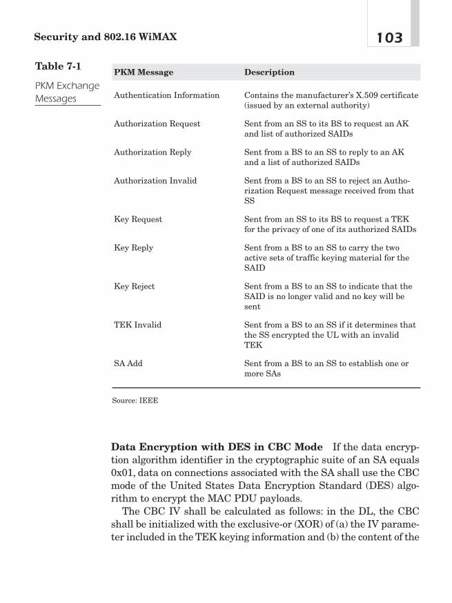
Data Encryption with DES in CBC Mode If the data encryp-tion algorithm identifier in the cryptographic suite of an SA equals0x01, data on connections associated with the SA shall use the CBCmode of the United States Data Encryption Standard (DES) algo-rithm to encrypt the MAC PDU payloads.
The CBC IV shall be calculated as follows: in the DL, the CBCshall be initialized with the exclusive-or (XOR) of (a) the IV parame-ter included in the TEK keying information and (b) the content of the
103Security and 802.16 WiMAX
PKM Message Description
Authentication Information Contains the manufacturer’s X.509 certificate(issued by an external authority)
Authorization Request Sent from an SS to its BS to request an AKand list of authorized SAIDs
Authorization Reply Sent from a BS to an SS to reply to an AKand a list of authorized SAIDs
Authorization Invalid Sent from a BS to an SS to reject an Autho-rization Request message received from thatSS
Key Request Sent from an SS to its BS to request a TEKfor the privacy of one of its authorized SAIDs
Key Reply Sent from a BS to an SS to carry the twoactive sets of traffic keying material for theSAID
Key Reject Sent from a BS to an SS to indicate that theSAID is no longer valid and no key will besent
TEK Invalid Sent from a BS to an SS if it determines thatthe SS encrypted the UL with an invalidTEK
SA Add Sent from a BS to an SS to establish one ormore SAs
Source: IEEE
Table 7-1
PKM ExchangeMessages
PHY Synchronization field of the latest DL-MAP. In the UL, the CBCshall be initialized with the XOR of (a) the IV parameter included inthe TEK keying information and (b) the content of the PHY Syn-chronization field of the DL-MAP that is in effect when the UL-MAPfor the UL transmission is created/received.
Residual termination block processing shall be used to encrypt thefinal block of plaintext when the final block is less than 64 bits.Given a final block having n bits, where n is less than 64, the next-to-last ciphertext block shall be DES encrypted a second time, usingthe electronic code book (ECB) mode, and the most significant n bitsof the result are XORed with the final n bits of the payload to gener-ate the short final cipherblock. In order for the receiver to decryptthe short final cipherblock, the receiver DES encrypts the next-to-last ciphertext block, using the ECB mode, and XORs the most sig-nificant n bits with the short final cipher block in order to recover theshort final clear text block.4
ConclusionThis chapter covered the security mechanisms built into the IEEE802.16 WiMAX specification. It is encouraging to note that, unlike its802.11 predecessors, WiMAX has powerful security measures at itslaunch. Although there is no such thing as an unhackable network,the incorporation of the two-stage security process (X.509 in theauthentication process and 56-bit DES for the service flow) will deterall but the most dedicated and knowledgeable hackers.
Chapter 7104
4“Air Interface for Fixed Broadband Wireless Access Systems,” 295.

WiMAX VoIP
CHAPTER 88
Copyright © 2005 by The McGraw-Hill Companies, Inc. Click here for terms of use.
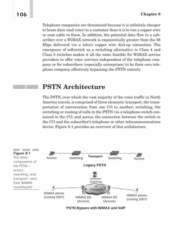
Telephone companies are threatened because it is infinitely cheaperto beam data (and voice) to a customer than it is to run a copper wireor coax cable to them. In addition, the potential data flow to a sub-scriber over a WiMAX network is exponentially greater than the 56Kbps delivered via a telco’s copper wire dial-up connection. Theemergence of softswitch as a switching alternative to Class 4 andClass 5 switches makes it all the more feasible for WiMAX serviceproviders to offer voice services independent of the telephone com-pany or for subscribers (especially enterprises) to be their own tele-phone company, effectively bypassing the PSTN entirely.
PSTN ArchitectureThe PSTN, over which the vast majority of the voice traffic in NorthAmerica travels, is comprised of three elements: transport, the trans-portation of conversation from one CO to another; switching, theswitching or routing of calls in the PSTN via a telephone switch con-tained in the CO; and access, the connection between the switch inthe CO and the subscriber’s telephone or other telecommunicationsdevice. Figure 8-1 provides an overview of this architecture.
Chapter 8106
Legacy PSTN
PSTN Bypass with WiMAX and VolP
TransportAccess AccessSwitching Switching
WiMAX phone(coming 2007) WiMAX phone
(coming 2007)WiMAX BS(Access)
WiMAX BS(Access)
Softswitch(Switching)
IP(Transport)
Figure 8-1The threecomponents ofthe PSTN—access,switching, andtransport—andtheir WiMAXcounterparts
As illustrated in Figure 8-1, WiMAX is a form of access to a widernetwork (PSTN, corporate LAN or WAN, or Internet). The MFJ of1984 opened transport to competition. The bandwidth glut currentlyhas made transport via IP backbone relatively inexpensive. The useof WiMAX as a backhaul mechanism will only accelerate that trend.Softswitch technologies (IP PBX, Class 4 and 5 replacements) offer aviable alternative to the switching facilities of the PSTN. TheTelecommunications Act of 1996 was intended to open the switchingand access facilities of the PSTN to competition. For a number of rea-sons, this has not happened. WiMAX presents a bypass technology ofthe telco’s copper wire access.
Voice Over WiMAX—The ChallengeThe emerging popularity of VoIP in the enterprise market coupledwith WiMAX raises the question: Can voice be transported over aWiMAX network? This chapter will discuss the objections to trans-mitting voice over WiMAX networks and will offer solutions to thoseobjections.
VoIPThe emergence of VoIP raises a wide range of possibilities. By virtueof transporting voice over a data stream, VoIP frees the voice streamfrom the confines of a voice-specific network and its associated plat-forms. VoIP can be received and transmitted via PCs, laptops, IP, andWi-Fi handsets. Where there is IP, there can be VoIP.
Origins of VoIP
In November 1988, Republic Telcom (yes, one “e”) of Boulder, Col-orado, received patent number 4,782,485 for a Multiplexed DigitalPacket Telephone System. The plaque from the Patent and Trade-mark Office describes it as follows:
107WiMax VoIP
A method for communicating speech signals from a first loca-tion to a second location over a digital communication mediumcomprising the steps of: providing a speech signal of predeter-mined bandwidth in analog signal format at said first location;periodically sampling said speech signal at a predeterminedsampling rate to provide a succession of analog signal samples;representing said analog signal samples in a digital formatthereby providing a succession of binary digital samples; divid-ing said succession of binary digital samples into groups ofbinary digital samples arranged in a temporal sequence; trans-forming at least two of said groups of binary digital samplesinto corresponding frames of digital compression.
Republic and its acquiring company, Netrix Corporation, appliedthis voice over data technology to the data technologies of the times(X.25 and frame relay) until 1998 when Netrix and other competitorsintroduced VoIP onto their existing voice over data gateways. Whileattempts had been made at Internet telephony from a software-onlyperspective, commercial applications were limited to using voice overdata gateways that could interface the PSTN to data networks. Voiceover data applications were popular in enterprise networks withoffices spread across the globe (eliminating international interofficelong-distance bills), in offices where no PSTN existed (installationsfor mining and oil companies), and for long-distance bypass (legiti-mate and illegitimate).
How Does VoIP Work?
The first process in an IP voice system is the digitization of thespeaker’s voice. The next step (and the first step when the user is ona handset connected to a gateway using a digital PSTN connection)is typically the suppression of unwanted signals and compression ofthe voice signal.This step has two stages. First, the system examinesthe recently digitized information to determine if it contains voicesignal or only ambient noise and discards any packets that do notcontain speech. Second, complex algorithms are employed to reducethe amount of information that must be sent to the other party.
Chapter 8108
Sophisticated codecs enable noise suppression and compression ofvoice streams. Compression algorithms (also known as codecs orcoders/decoders) include G.723, G.728, and G.729. G.711 is the codecfor uncompressed voice at 64 Kbps.
Following compression, voice must be packetized and VoIP signal-ing protocols added. Some storage of data occurs during the processof collecting voice data because the transmitter must wait for a cer-tain amount of voice data to be collected before it is combined to forma packet and transmitted via the network. Protocols are added to thepacket to facilitate its transmission across the network. For example,each packet will need to contain the address of its destination, asequencing number in case the packets do not arrive in the properorder, and additional data for error checking.
Because IP is a protocol designed to interconnect networks ofvarying kinds, substantially more processing is required than insmaller networks. The network-addressing system can often be verycomplex, requiring a process of encapsulating one packet insideanother and, as data moves along, repackaging, readdressing, andreassembling the data.
When each packet arrives at the destination computer, itssequencing is checked to place the packets in the proper order. Adecompression algorithm is used to restore the data to its originalform, and clock-synchronization and delay-handling techniques areused to ensure proper spacing. Because data packets are transportedvia the network by a variety of routes, they do not arrive at their des-tination in order. To correct this situation, incoming packets arestored for a time in a jitter buffer to wait for late-arriving packets.The length of time in which data are held in the jitter buffer varies,depending on the characteristics of the network.
VoIP Signaling Protocols
VoIP signaling protocols, H.323 and SIP, set up the route for themedia stream or conversation over an IP network. Gateway controlprotocols, such as Media Gateway Control Protocol (MGCP), and sig-naling protocols establish control and status in media and signalinggateways.
109WiMax VoIP
Once the route of the media stream has been established, routing(User Diagram Protocol [UDP] and Transmission Control Protocol[TCP]) and transporting (Real-Time Transport Protocol [RTP]) themedia stream (conversation) are the function of routing and trans-port protocols. Routing protocols, such as UDP and TCP, could becompared to the switching function described in Chapters 2 and 3.
RTP would be analogous to the transport function in the PSTN.The signaling and routing functions establish what route the mediastream will take when the routing protocols delivers the bits, that is,the conversation.
Setting up a VoIP call is roughly similar to setting up a circuit-switched call on the PSTN. A media gateway or IP phone must beloaded with the parameters to allow proper media encoding and theuse of telephony features. Inside the media gateway is an intelligententity known as an endpoint. When the calling and called partiesagree on how to communicate and the signaling criteria is estab-lished, the media stream over which the packetized voice conversa-tion will flow is established. Signaling establishes the virtual circuitover the network for that media stream. Signaling is independent ofthe media flow. It determines the type of media to be used in a calland is concurrent throughout the call.Two types of signaling are cur-rently popular in VoIP: H.323 and Session Initiation Protocol (SIP).1
Figure 8-2 details the relationship between signaling and mediaflow. VoIP’s relationship between transport and signaling resemblesPSTN’s, in that SS7 is out-of-channel signaling, as is used in VoIP.
H.323 H.323 is the International Telecommunications Union (ITU-T) recommendation for packet-based multimedia communica-tion. H.323 was developed before the emergence of VoIP for video overa local area network (LAN). As it was not specifically designed forVoIP, H.323 has faced a good deal of competition from a competingprotocol, SIP, which was designed specifically for VoIP over any sizeof network. H.323 has enjoyed a first mover advantage, and therenow exists a considerably installed base of H.323 VoIP networks.
Chapter 8110
1Bill Douskalis, IP Telephony: The Integration of Robust VoIP Services (Upper SaddleRiver, NJ: Prentice Hall, 2000).
H.323 is made up of a number of subprotocols. It uses protocolH.225.0 for registration, admission, status, call signaling, and con-trol. It also uses protocol H.245 for media description and control,terminal capability exchange, and general control of the logical chan-nel carrying the media stream(s). Other protocols make up the com-plete H.323 specification, which presents a protocol stack for H.323signaling and media transport. H.323 also defines a set of call con-trol, channel setup, and codec specifications for transmitting real-time video and voice over networks that don’t offer guaranteedservice or quality of service. As a transport, H.323 uses RTP, anInternet Engineering Task Force (IETF) standard designed to han-dle the requirements of streaming real-time audio and video via theInternet.2
SIP: Alternative Softswitch Architecture? If the worldwidePSTN could be replaced overnight, the best candidate architectureat this time would be based on VoIP and SIP. Much of the VoIPindustry has been based on offering solutions that leverage existingcircuit-switched infrastructure (for example, VoIP gateways thatinterface a private branch exchange [PBX] and an IP network). Atbest, these solutions offer a compromise between circuit- and packet-switching architectures with resulting liabilities of limited features,expensive-to-maintain circuit-switched gear, and questionable QoSand reliability, as a call is routed between networks based on thosetechnologies. SIP is an architecture that potentially offers more fea-tures than a circuit-switched network.
111WiMax VoIP
Signaling:H.323 or SIP
Traffic: RTP
Softswitch
IP PhoneIP Phone
Figure 8-2Signaling andtransportprotocols usedin VoIP
2Ibid., 9.
SIP is a signaling protocol. It uses a text-based syntax similar toHypertext Transfer Protocol (HTTP), as used in web addresses. Pro-grams that are designed for parsing of HTTP can be adapted easilyfor use with SIP. SIP addresses, known as SIP URLs (or uniformresource locators), take the form of web addresses. A web addresscan be the equivalent of a telephone number in an SIP network. Inaddition, PSTN phone numbers can be incorporated into an SIPaddress for interfacing with the PSTN. An e-mail address is portable.Using the proxy concept, one can check his or her e-mail from anyInternet-connected terminal in the world. Telephone numbers, sim-ply put, are not portable; they ring at only one physical location. SIPoffers a mobility function that can follow subscribers to the nearestphone at a given time.
Like H.323, SIP handles the setup, modification, and teardown ofmultimedia sessions, including voice. While it works with mosttransport protocols, its optimal transport protocol is RTP. Figure 8-2shows how SIP functions as a signaling protocol, while RTP is thetransport protocol for a voice conversation. SIP was designed as apart of the IETF multimedia data and control architecture. It isdesigned to interwork with other IETF protocols such as SessionDescription Protocol (SDP), RTP, and Session Announcement Proto-col (SAP). It is described in the IETF’s RFC 2543. Many in the VoIPand softswitch industry believe that SIP will replace H.323 as thestandard signaling protocol for VoIP.
SIP is part of the IETF standards process and is modeled on otherInternet protocols such as Simple Mail Transfer Protocol (SMTP)and HTTP. It is used to establish, change, and tear down (end) callsbetween one or more users in an IP-based network. In order to pro-vide telephony services, a number of different standards and proto-cols need to come together—specifically to ensure transport (RTP)signaling with the PSTN, guarantee voice quality (Resource Reser-vation Protocol [RSVP]), provide directories (Lightweight DirectoryAccess Protocol [LDAP]), authenticate users (remote authenticationdial-in user service [RADIUS]), and scale to meet anticipated growthcurves.
How Does SIP Work? SIP is focused on two classes of networkentities: clients (also called user agents [UAs]) and servers. VoIPcalls on SIP to originate at a client and terminate at a server. Types
Chapter 8112

of clients in the technology currently available for SIP telephonyinclude a personal computer (PC) loaded with a telephony agent ora SIP telephone. Clients can also reside on the same platform as aserver. For example, a PC on a corporate WAN might be the serverfor the SIP telephony application, but it might also function as auser’s telephone (client).
SIP Architecture SIP is a client-server architecture. The client inthis architecture is the UA. The UA interacts with the user. It usu-ally has an interface toward the user in the form of a PC or an IPphone (SIP phone in this case). There are four types of SIP servers:UA server, redirect server, proxy server, and a registrar. The type ofSIP server used determines the architecture of the network.
SwitchingIn the PSTN, the switching function is performed in the CO, whichcontains a Class 5 switch for local calls and a Class 4 switch for long-distance calls. A Class 5 switch can cost upwards of tens of millionsof dollars and is very expensive to maintain. This expense has keptcompetitors out of the local calling market. A new technology knownas softswitch is far less expensive in terms of purchase and mainte-nance. Potentially, softswitch allows a competitive service provider tooffer their own service without having to route calls through theincumbent service provider’s CO. The following pages describesoftswitch.
Softswitch (aka Gatekeeper, Media GatewayController)
In a VoIP network, a softswitch is the intelligence that coordinatescall control, signaling, and features that make a call across a net-work or multiple networks possible. A softswitch primarily performscall control (call set-ups and teardowns). Once a call is set up, con-nection control ensures that the call stays up until the originating orterminating user releases it. Call control and service logic refer to
113WiMax VoIP

the functions that process a call and offer telephone features. Exam-ples of call control and service logic functions include recognizingthat a party has gone off hook and that a dial tone should be pro-vided, interpreting the dialed digits to determine where the call is tobe terminated, determining if the called party is available or busy,and finally, recognizing when the called party answers the phoneand when either party subsequently hangs up and then recordingthese actions for billing.
A softswitch coordinates the routing of signaling messagesbetween networks. Signaling coordinates actions associated with aconnection to the entity at the other end of the connection. To set upa call, a common protocol must be used that defines the informationin the messages and that is intelligible at each end of the networkand across dissimilar networks. The main types of signaling asoftswitch performs are peer-to-peer for call control and softswitch-to-gateway for media control. For signaling, the predominant proto-cols are SIP, Signaling System 7 (SS7), and H.323. For media control,the predominant signaling protocol is MGCP.
As a point of introduction to softswitch, it is necessary to clarifythe evolution to softswitch and define media gateway controller andgatekeeper, the precursors to softswitch. Media Gateway Controllers(MGC) and gatekeepers (essentially synonymous terms for the ear-liest forms of softswitch) were designed to manage low-density (rel-ative to a carrier grade solution) voice networks. MGC communicateswith both the signaling gateway and the media gateway to providethe necessary call processing functions. The MGC uses either MGCPor MEGACO/H.248 (described in a later chapter) for intergatewaycommunications.
Gatekeeper technology evolved out of H.323 technology (a VoIPsignaling protocol described in the next chapter). As H.323 wasdesigned for LANs, an H.323 gatekeeper can only manage activitiesin a zone (read LAN but not specifically an LAN). A zone is a collec-tion of one or more gateways managed by a single gatekeeper. Agatekeeper should be thought of as a logical function, not a physicalentity. The functions of a gatekeeper are address translation (that is,a name or e-mail address for a terminal or gateway and a transportaddress) and admissions control (authorizes access to the network).
Chapter 8114
As VoIP networks got larger and more complex, managementsolutions with far greater intelligence became necessary. Greater callprocessing power was needed, as was the ability to interface signal-ing between IP networks with the PSTN (VoIP signaling protocols toSS7). Other drivers included the need to integrate features on thenetwork and interface disparate VoIP protocols. Thus was born thesoftswitch.
The softswitch provides usage statistics to coordinate billing andto track operations and administrative functions of the platformwhile interfacing with an application server to deliver value-addedsubscriber services. The softswitch controls the number and type offeatures provided. It interfaces with the feature/application serverto coordinate features (conferencing, call forwarding, and so on) fora call.
Physically, a softswitch is software hosted on a server chassisfilled with IP boards and includes the call control applications anddrivers.3 Very simply, the more powerful the server, the more capablethe softswitch. That server need not be colocated with other compo-nents of the softswitch architecture.
Other Softswitch Components
Softswitch’s key advantage over its circuit-switched predecessor isutilizing distributed architecture. That is, its components need notbe colocated. Those components include signaling gateway, mediagateway, and application server.
Signaling Gateway Signaling gateways are used to terminatesignaling links from PSTN networks or other signaling points. TheSS7 signaling gateway serves as a protocol mediator (translator)between the PSTN and IP networks. That is, when a call originatesin an IP network using H.323 as a VoIP protocol and must terminatein the PSTN, a translation from the H.323 signaling protocol to SS7is necessary in order to complete the call. Physically, the signaling
115WiMax VoIP
3Ibid.
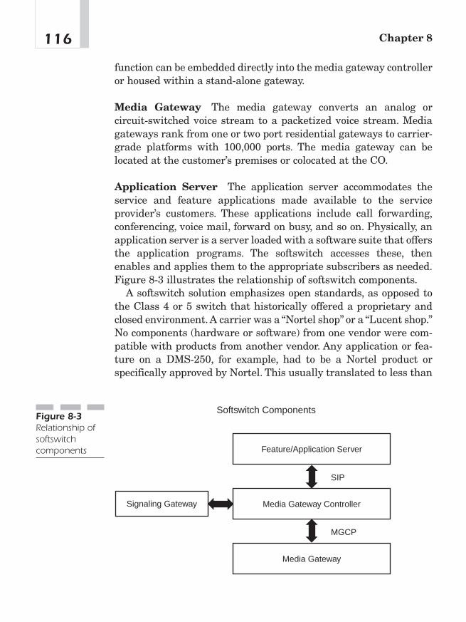
function can be embedded directly into the media gateway controlleror housed within a stand-alone gateway.
Media Gateway The media gateway converts an analog orcircuit-switched voice stream to a packetized voice stream. Mediagateways rank from one or two port residential gateways to carrier-grade platforms with 100,000 ports. The media gateway can belocated at the customer’s premises or colocated at the CO.
Application Server The application server accommodates theservice and feature applications made available to the serviceprovider’s customers. These applications include call forwarding,conferencing, voice mail, forward on busy, and so on. Physically, anapplication server is a server loaded with a software suite that offersthe application programs. The softswitch accesses these, thenenables and applies them to the appropriate subscribers as needed.Figure 8-3 illustrates the relationship of softswitch components.
A softswitch solution emphasizes open standards, as opposed tothe Class 4 or 5 switch that historically offered a proprietary andclosed environment. A carrier was a “Nortel shop” or a “Lucent shop.”No components (hardware or software) from one vendor were com-patible with products from another vendor. Any application or fea-ture on a DMS-250, for example, had to be a Nortel product orspecifically approved by Nortel. This usually translated to less than
Chapter 8116
Feature/Application Server
Media Gateway Controller
Media Gateway
SIP
MGCP
Signaling Gateway
Softswitch ComponentsFigure 8-3Relationship ofsoftswitchcomponents
competitive pricing for those components. Softswitch open standardsare aimed at freeing service providers from vendor dependence andthe long and expensive service development cycles of legacy switchmanufacturers.
Service providers are concerned with whether a softswitch solu-tion can transmit a robust feature list identical to that found on a5ESS Class 5 switch, for example. Softswitch offers the advantage ofallowing a service provider to integrate third-party applications oreven write its own while interoperating with the features of thePSTN via SS7. This is potentially the greatest advantage to a serviceprovider presented by softswitch technology.
Features reside at the application layer in softswitch architecture.The interface between the Call Control Layer and specific applica-tions is Application Program Interface (API).Writing and interfacingan application with the rest of the softswitch architecture occurs inthe Service Creation Environment.
VoIP and Softswitch Pave the Way for VoiceOver WiMAX
A number of attempts have been made to deploy voice services viawireless local loop (WLL): for instance, using wireless technologies(not WiMAX) to offer telephone service in underserved or third-worldmarkets. As these services have been limited to voice services, theyhave not caught on with a mass market. WiMAX is different, as it isa protocol for Ethernet over a wireless medium. The building blocksfor a potential alternative to the PSTN now fall into place. Not onlydoes a WiMAX network offer a potential bypass of the PSTN forvoice services, it also offers broadband Internet and its incumbentsuite of services.
Objections to VoIP Over WiMAXLike concerns over WiMAX as a whole, five major objections arise toadopting VoIP over WiMAX: voice quality as it relates to QoS, security,E911, Communications Assistance to Law Enforcement Agencies
117WiMax VoIP

(CALEA), and range. Many suspect that there is an adverse trade-offbetween the predictability (QoS) of copper wires that deliver voice toresidences and the unpredictability of the airwaves as utilized byWiMAX.
Objection One: Voice Quality of WiMAX VoIP
Despite the fact that telephone companies in the United States arelosing thousands of lines per month to cell phone service providers,many believe that voice over a cell phone connection would deliverinferior voice quality and, as a result, is not a viable alternative tothe copper wires of the PSTN.
Measuring Voice Quality in WiMAX VoIP How does one mea-sure the difference in voice quality between a WiMAX VoIP and thePSTN? As the VoIP industry matures, new means of measuring voicequality are coming on the market. Currently, two tests award somesemblance of a score for voice quality. The first, Mean Opinion Score(MOS), is a holdover from the circuit-switched voice industry, andthe other, Perceptual Speech Quality Measurement (PSQM), hasemerged with VoIP’s increasing popularity.
Mean Opinion Score (MOS) Can voice quality as a function of QoSbe measured scientifically? The telephone industry employs a sub-jective rating system known as the MOS to measure the quality ofthe telephone connections. The measurement techniques aredefined in ITU-T P.800 and are based on the opinions of many test-ing volunteers who listen to a sample of voice traffic and rate thequality of that transmission. The volunteers listen to a variety ofvoice samples and are asked to consider factors such as loss, circuitnoise, side tone, talker echo, distortion, delay, and other transmis-sion problems. The volunteers then rate the voice samples from 1 to5, with 5 being “Excellent” and 1 being “Bad.” The voice samples arethen awarded a Mean Opinion Score, or MOS. A MOS of 4 is con-sidered “toll quality.”
It should be stated here that the voice quality of VoIP applicationscan be engineered to be as good or better than the PSTN. Recent
Chapter 8118
research performed by the Institute for Telecommunications Sci-ences in Boulder, Colorado, compared the voice quality of trafficrouted through VoIP gateways with the PSTN. Researchers were feda variety of voice samples and were asked to determine if the sam-ple originated with the PSTN or from the VoIP gateway traffic. Thetest indicated that the voice quality of the VoIP gateway routed traf-fic was “indistinguishable from the PSTN.”4 It should be noted thatthe IP network used in this test was a closed network, not the publicInternet or other long-distance IP network. This report indicatesthat quality media gateways can deliver voice quality on the samelevel as the PSTN. The challenge then shifts to ensuring the IP net-work can deliver similar QoS to ensure good voice quality. This chap-ter will explain how measures can be taken to engineer voice-specificsolutions into a wireless network to ensure voice quality equals thePSTN.
Perceptual Speech Quality Measurement (PSQM) Another means oftesting voice quality is known as PSQM. This method, based onITU-T Recommendation P.861, specifies a model to map actualaudio signals to their representations inside the head of a human.Voice quality consists of a mix of objective and subjective parts; itvaries widely among the different coding schemes and the types ofnetwork topologies used for transport. In PSQM, measurements ofprocessed (compressed, encoded, and so on) signals derived from aspeech sample are collected, an objective analysis is performed com-paring the original and the processed version of the speech sample,and an opinion as to the quality of the signal processing functionsthat processed the original signal is rendered. Unlike MOS scores,PSQM scores result in an absolute number, not a relative compari-son between the two signals.5 This is valuable because vendors canstate the PSQM score for a given platform (as assigned by an impar-tial testing agency). Service providers can then make at least partof their buying decision based on the PSQM score of the platform.
119WiMax VoIP
4Andrew Craig, “Qualms of Quality Dog Growth of IP Telephony,” Network News(November 11, 1999): 3.5Bill Douskalis, IP Telephony, 242—243.
Detractors to Voice Quality in WiMAX What specificallydetracts from good voice quality in a WiMAX environment? Latency,jitter, packet loss, and echo are the problems. With proper engineer-ing, the impact of these factors on voice quality can be minimized,and voice quality equal to or better than the PSTN can be achievedon WiMAX networks.
Latency (aka Delay) Voice as a wireless IP application presentsunique challenges for WiMAX networks. Primary among these isacceptable audio quality resulting from minimized network delay ina mixed voice and data environment. Ethernet, wired or wireless,was not designed for real-time streaming media or guaranteedpacket delivery. Congestion without traffic differentiation on thewireless network can quickly render voice unusable. QoS measuresmust be taken to ensure voice packet delays remain under 100 ms.
Voice signal processing at the sending and receiving ends, whichincludes the time required to encode or decode the voice signal fromanalog or digital form into the voice-coding scheme selected for thecall and vice versa, adds to the delay. Compressing the voice signalwill also increase the delay: the greater the compression, the greaterthe delay. Where bandwidth costs are not a concern, a serviceprovider can utilize G.711, uncompressed voice (64 Kbps), whichimposes a minimum of delay due to the lack of compression.
On the transmit side, packetization delay is another factor thatmust be entered into the calculations. The packetization delay is thetime it takes to fill a packet with data: the larger the packet size, themore time required. Using smaller packet sizes can shorten thisdelay but will increase the overhead because more packets contain-ing similar information in the header have to be sent. Balancingvoice quality, packetization delay, and bandwidth utilization effi-ciency is very important to the service provider.6
How much delay is too much? Of all the factors that degrade VoIP,latency (or delay) is the greatest problem. Recent testing by MierLabs offers a metric as to how much latency is acceptable or compa-rable to toll quality, the voice quality offered by the PSTN. Latency
Chapter 8120
6Ibid., 230–231.
less than 100 ms does not affect toll-quality voice. However, latencyover 120 ms is discernable to most callers, and at 150 ms the voicequality is noticeably impaired, resulting in less than toll-qualitycommunication. The challenge for VoIP service providers and theirvendors is to keep the latency of any conversation on their networkfrom exceeding 100 ms.7 Humans are intolerant of speech delays ofmore than about 200 ms.As mentioned earlier, ITU-T G.114 specifiesthat delay is not to exceed 150 ms one-way or 300 ms round trip. Thedilemma is that while elastic applications (e-mail, for example) cantolerate a fair amount of delay, they usually try to consume everypossible bit of network capacity. In contrast, voice applications needonly a small amount of the network, but that amount has to be avail-able immediately.8
Dropped Packets In IP networks, a percentage of the packets can belost or delayed, especially in periods of congestion. Also, some pack-ets are discarded due to errors that occurred during transmission.Lost, delayed, and damaged packets result in substantial deteriora-tion of voice quality. In conventional error correction techniques usedin other protocols, incoming blocks of data containing errors are dis-carded, and the receiving computer requests the retransmission ofthe packet; thus, the message that is finally delivered to the user isexactly the same as the message that originated.
As VoIP (and tangentially WiMAX VoIP) systems are time sensi-tive and cannot wait for retransmission, more sophisticated errordetection and correction systems are used to create sound to fill inthe gaps. This process stores a portion of the incoming speaker’svoice; then, using a complex algorithm to approximate the contentsof the missing packets, new sound information is created to enhancethe communication. Thus, the sound the receiver hears is not exactlythe sound transmitted; rather, portions have been created by the sys-tem to enhance the delivered sound.9
121WiMax VoIP
7Mier Communications, “Lab Report—QoS Solutions,” February 2001, p. 2, www.sitaranetworks.com/solutions/pdfs/mier_report.pdf.8John McCullough and Daniel Walker, “Interested in VoIP? How to Proceed,” Busi-ness Communications Review (April 1999): 16—22.9Report to Congress on Universal Service, CC Docket No. 96—45, white paper on IPVoice Services, March 18, 1998, www.von.org/docs/whitepap.pdf.

Jitter Jitter occurs because packets have varying transmissiontimes. It is caused by different queuing times in the routers and pos-sible different routing paths. Jitter results in unequal time spacingbetween the arriving packets and requires a jitter buffer to ensurea smooth, continuous playback of the voice stream.
The chief correction for jitter is to include an adaptive jitter buffer.An adaptive jitter buffer can dynamically adjust to accommodate forhigh levels of delay that can be encountered in wireless networks.
A Word About Bit Rate (or Compression Rate) The bit rate, which isthe number of bits per second delivered by the speech encoder, deter-mines the bandwidth load on the network. It is important to notethat the packet headers (IP, UDP, and RTP) also add to the band-width. Speech quality generally increases with the bit rate:Very sim-ply put, the greater the bandwidth, the greater the speech quality.
Solution: Voice Codecs Designed forVoIP, Especially VoIP Over WiMAXMany of the detractors to good speech quality in VoIP over WiMAXcan be overcome by engineering a variety of fixes into the speechcodecs used in both circuit- and packet-switched telephony. The fol-lowing sections will describe speech coding and explain how itapplies to speech quality.
Modifying Voice Codecs to Improve VoiceQuality
One of the first processes in the transmission of a telephone call isthe conversion of an analog signal (the wave of the voice entering thetelephone) into a digital signal.This process is called pulse code mod-ulation (PCM). PCM is a four-step process consisting of pulse ampli-tude modulation (PAM) sampling, companding, quantization, andencoding. Encoding is a critical process in VoIP and WiMAX VoIP. To
Chapter 8122
date, voice codecs used in VoIP (packet switching) are taken directlyfrom PSTN technologies (circuit switching). Cell phone technologiesuse PSTN voice codecs. New software in the WiMAX VoIP industryutilizes modified PSTN codecs to deliver voice quality comparable tothe PSTN.
Popular Speech Codecs Speech codecs, based largely on com-pression algorithms, are a significant determinant in the quality ofa telephone conversation.
The QoS Solution: Fix Circuit-Switched Voice Codecs in a PacketSwitched, Wireless World withEnhanced Speech-ProcessingSoftwareIf circuit-switching voice codecs are the challenge to good QoS inwireless, packet-switched networks, what, then, is the fix for outdatedvoice codecs? An emerging market of enhanced speech-processingsoftware corrects for the shortcomings of traditional voice codecs,which were designed decades ago for a circuit-switched PSTN. Theserecent developments in VoIP software provide QoS enhancementsolutions for IP telephony in the terminal with very high voice qual-ity even with severe network degradations caused by jitter andpacket loss. These VoIP QoS enhancements should provide WiMAXVoIP speech quality comparable to that of the PSTN. Also, speechquality should degrade gradually as packet loss increases. Moderatepacket loss percentages should be inaudible.Table 8-1 shows the rela-tionship between speech codecs and MOS scores.
Enhanced Speech-Processing Software New speech-processingalgorithms provide for diversity; this means that an entire speechsegment is not lost when a single packet is lost. Diversity is achievedby reorganizing the representation of the speech signal. Diversity
123WiMax VoIP
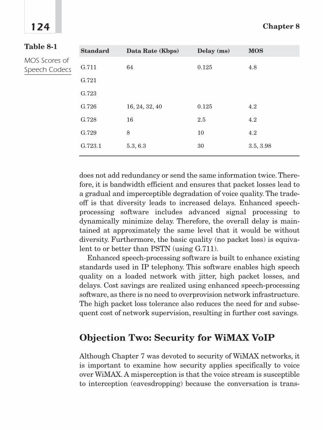
does not add redundancy or send the same information twice. There-fore, it is bandwidth efficient and ensures that packet losses lead toa gradual and imperceptible degradation of voice quality. The trade-off is that diversity leads to increased delays. Enhanced speech-processing software includes advanced signal processing todynamically minimize delay. Therefore, the overall delay is main-tained at approximately the same level that it would be withoutdiversity. Furthermore, the basic quality (no packet loss) is equiva-lent to or better than PSTN (using G.711).
Enhanced speech-processing software is built to enhance existingstandards used in IP telephony. This software enables high speechquality on a loaded network with jitter, high packet losses, anddelays. Cost savings are realized using enhanced speech-processingsoftware, as there is no need to overprovision network infrastructure.The high packet loss tolerance also reduces the need for and subse-quent cost of network supervision, resulting in further cost savings.
Objection Two: Security for WiMAX VoIP
Although Chapter 7 was devoted to security of WiMAX networks, itis important to examine how security applies specifically to voiceover WiMAX. A misperception is that the voice stream is susceptibleto interception (eavesdropping) because the conversation is trans-
Chapter 8124
Standard Data Rate (Kbps) Delay (ms) MOS
G.711 64 0.125 4.8
G.721
G.723
G.726 16, 24, 32, 40 0.125 4.2
G.728 16 2.5 4.2
G.729 8 10 4.2
G.723.1 5.3, 6.3 30 3.5, 3.98
Table 8-1
MOS Scores ofSpeech Codecs
mitted over the airwaves. Given the double encryption process ofWiMAX (X.509 and 56-bit DES), it would be extremely difficult totap into such a conversation.
Objection Three: CALEA and E911
The circuit-switched industry’s common objection to VoIP concerns atelecommunications carrier’s compliance with CALEA and E911, thelegal requirements for primary line telephone service providers inthe United States. The laws requiring telephone companies to pro-vide these services were made before the Internet came to main-stream America. Although there are technological means ofproviding these services in a number of circumstances, the first ques-tion should concern the service provider’s obligation in providingthese services.
E911
A number of E911 solutions are coming on the market at the time ofthis writing. First, some solutions overflow from the cell phoneindustry where E911 will soon be a requirement. Another solution isto include global positioning satellite (GPS) technology in a WiMAXVoIP handset. That way, the exact location of the handset would beknown at any time.
More concretely, E911 compliance is possible by registering the IPtelephone with the PSTN’s PSAP database, which maps a telephonenumber to a physical location. For those who use their IP telephoneas a static home or office phone, this may present a suitable solution.For those who take their IP phone traveling, it becomes necessary toreregister that handset’s location upon being installed at the newlocation.
Communications Assistance to Law Enforcement Agencies(CALEA) This requirement may be relaxed in a forthcoming reg-ulatory regime outlined by former FCC Chairman Michael Powell inan October 30, 2002 address at the University of Colorado. In that
125WiMax VoIP

speech, Chairman Powell conceded that the CALEA law wasdesigned for the circuit-switched world and is (at the time of thatspeech) difficult to comply with in a WiMAX VoIP environment. Asa result, and in the interest of promoting all that WiMAX and simi-lar technologies have to offer, Chairman Powell hinted that suchrequirements would have to be relaxed.
Very simply put, CALEA calls for two capabilities. First, it calls forthe collection of call details: who called whom, when, and for howlong. This is not difficult in a VoIP environment, as most softswitchproducts can collect call detail records (CDRs). Second, and this isthe hard part, CALEA calls for the collection of the content of thecall, that is, a recording of the call. Given the packetization of thevoice stream and its dispersal over an IP network, this is a techni-cally difficult task. Some recent products can provide this capability;however, these products are very expensive.
At the time of this writing, a number of VoIP service providershave come up with solutions that take advantage of existing broad-band availability in homes and businesses. VoIP service providers,such as Vonage and Packet8, offer their services online and sell ana-log telephone adapter kits in retail outlets. While they are not legallybound to do so, these services do offer some limited CALEA compli-ance via their softswitch, which can provide some details of the tar-geted call depending on the routing of the call. In short,market-leading softswitch vendors do have the capability to beCALEA compliant.
Architecture of WiMAX VoIP:Putting It All TogetherWhat is the architecture for an alternative to the PSTN? The PSTNis comprised of three elements: access (the wires to a residence, forexample), switching (the switches in the CO), and transport (long-distance ATM networks or IP fiber optic backbones). Figure 8-4shows how voice services can be handled via an alternative network
Chapter 8126
where access is performed by WiMAX (or associated protocols),switching is done by a softswitch, and transport is handled by IPfiber optic backbone. The common denominator in this alternative tothe PSTN is VoIP. Wherever there is access to an IP stream, VoIP ispossible. Softswitch technologies make managing voice traffic overan IP network possible.
WiMAX VoIP Phones
It won’t be long until many WISPs begin to incorporate VoIP intotheir wireless service offerings. The following sections describe themechanics of rolling out such services.
Case Study: AmberWaves WISP WiMAX VoIP AmberWaves isa WISP in northwest Iowa. One of their clients has three offices with35 employees linked by a WiMAX-like network. The greatest dis-tance between the three offices is 19 miles.
This wireless network allows the firm to be its own internal dataand voice service provider. The use of WiMAX-like service frees thefirm from local and long-distance telephone bills. The end usersreport that the QoS on the network is better than with the framerelay circuit they used previously. Figure 8-5 shows how this couldwork with WiMAX.
127WiMax VoIP
WiMAX phone(coming 2007)
WiMAX phone(coming 2007)
WiMAX BS(Access)
WiMAX BS(Access)
Softswitch(Switching)
IP(Transport)
PSTN Bypass with WiMAX and VolP
Figure 8-4An alternative tothe PSTN:WiMAX asaccess,softswitch forswitching, andIP backbones astransport

ConclusionAt the present time, the RBOCs of North America are losing thou-sands of lines per month; this is the first loss in coverage percentage-wise since the Great Depression. Most of the blame for these lossesis placed on cell phones. SBC Communications reports a loss of threemillion phone lines (called access lines) between 2000 and 2002 andreports it will lose another three million lines in 2002. Other marketanalysts point to a number of influences.
Cell phones have claimed a number of those land lines. Many sub-scribers find cell phones more convenient and have “cut the wire.”The monthly subscription cost of a cell phone has dropped, and manysubscribers are dropping their land lines. Comparisons between theland line and cell phone seem to favor the cell phone’s convenienceover the land line’s reputation for reliability and QoS.
Another explanation for one of the leading RBOC’s loss of almostsix million lines in a little over two years is broadband. Because thetraditional 64 Kbps copper pair service provided to the majority of
Chapter 8128
Tower-mountAntenna
Wireless
Voice Router
PBX Switch
POTS Phone
Tower-mountAntenna
Wireless
Voice Router
PBX Switch
POTS Phone
Figure 8-5Linking officeswith WiMAXVoIP

North American residences and small businesses was designedentirely for voice service with a limited data service capability (56Kbps with some 10 percent of households able to receive DSL serviceat data rates around 256 Kbps), there does not appear to be anappreciable level of “future proofing” built into the PSTN. Many DSLand cable television subscribers have either taken up VoIP applica-tions for their voice service or have relied on cell phones for voice andtheir broadband connection for Internet access. DSL subscribershave canceled their second phone lines and now use their primaryline for both DSL and telephone. Cable subscribers have canceledtheir land line altogether.
129WiMax VoIP

This page intentionally left blank
WiMAX IPTV
CHAPTER 99
Copyright © 2005 by The McGraw-Hill Companies, Inc. Click here for terms of use.
WISP WiMAX Triple Play?Many telecommunications strategists speak of the elusive triple playof telecommunications where TV (video), voice, and data are allavailable from one service provider on one service medium and billedon one monthly, converged bill. At the current time, this is notentirely possible from existing service providers on existing infra-structure. Internet Protocol Television (IPTV) is a video technologythat competes favorably with cable and broadcast television.
IPTV: Competing with Cable TVand Satellite TVThe rollout of digital networking infrastructure is opening the doorfor telcos and operators to offer converged services comprising broad-band Internet access and IP-based TV and entertainment. TV (orvideo) over IP is a broad streaming solution that includes severalapplications, all of which can be implemented on WiMAX. IPTV isused in the following applications:
■ TV (instead of cable TV) to the living room
■ Time-shifted TV or personal video recorder (PVR)
■ Interactive TV
■ TV to the desktop
One of the inhibitors of broadband deployment in recent years hasbeen the lack of broadband applications.This, in turn, resulted in lowreturn on investment in broadband infrastructure. The viability ofthe broadband business model is becoming much more attractivewith the introduction of IPTV services, which are a major revenueengine for telcos and ISPs.
With WiMAX IPTV, WISPs using WiMAX can offer a triple play ofvoice, video, and data to their subscribers. Customers receive con-verged services on a single pipe and interface with a single providerfor all communication needs, resulting in easier technical mainte-nance, streamlined billing, and hence improved customer service. It
Chapter 9132

is possible to target specific channels at small groups of viewers,based on predefined viewing profiles. Interactive IPTV also letsviewers create customized profiles themselves, based on their per-sonal viewing habits. Table 9-1 provides a comparison of WiMAX toexisting telecommunications infrastructures.
133WiMax IPTV
Element Legacy Cable WiMAX
Telephone
Table 9-1
WiMAX vs.Telco vs. CableTV for TriplePlay
Ability of infra-structure todeliver video,voice, and data
Largely voice-only;aging, non-video-capable, band-width-limitedcopper wire(mostly dial-uponly); limited per-centage of U.S.COs can delivergeneric digitalsubscriber line(XDSL) service
Aging plant;mostly coax cableTV delivery only;increasing bidirec-tional cablemodem service incities and suburbs;most promisingvoice is third party(Vonage, Packet8,and so on)
High bandwidthcapacity withleast expensiveinfrastructure andoperating costs todeliver voice,video, and data
Networkmanagement
Limited to CO and some outsideplants; otherwiseexpensive truckroll
Limited networkmanagement sys-tem; truck rollsrequired
SNMP capable—can determineproblems down tothe IP address ordevice; truck rollfor emergenciesonly
Bandwidth XDSL for residen-tial service usu-ally less than 1Mbps download;service limited tomore densely pop-ulated markets
Focused on analogvideo; where avail-able, most dataservices do notexceed 1 Mbpswith limited QoS
Depending on BS,the “sky’s thelimit”; requires 2Mbps for com-pressed MPEG 4stream to deliverstandard TV pro-gramming
Easily deployed tonew markets?
With exception offiber to the homeat $1,400 perhousehold, noteconomically feasible
Right-of-way andcity franchiseissues precludetimely deploymentof service
No right-of-wayissues; per FCC,no municipal con-cessions required;can be rapidlydeployed
Regardless of the terminology, the process is the same: A TV pro-gram is converted to IP and streamed to the viewer. The same pro-gramming happens at the same time as cable or satellite TV.Assuming the viewer watches the programming on his or her TV setusing an IP set top box (STP), the viewer’s experience is no differentthan the experience of anyone else watching cable or satellite TV.
What’s disruptive about this technology is that it’s not limited toa traditional TV service provider. It is often called telco TV, as tele-phone companies feel the need to compete with cable TV companiesoffering voice services. In that scenario, the telephone companyneeds to offer broadband Internet access via variants of asymmetricdigital subscriber line (ADSL).
Industry analysts refer to this cable TV vs. telco competition as aduopoly. WiMAX makes for a third force where WISPs offer data,voice, and the same TV programming as the other providers. A newterm is creeping into that lexicon: WiMAX IPTV.
How It WorksKey technical components of the IPTV service provider’s solutioninclude a few key components that mesh traditional TV program dis-tribution with IP technologies.
1. Content and Programming—The IPTV service provider hassecured strategic transport agreements with nationalprogrammers and broadcasters (in North America, ESPN, CNN,and so on) to offer a competitive channel line-up, simplifying theacquisition process for the partner service provider (a WiMAX-powered ISP for example). The IPTV service provider receivesthis content directly from the programmers and feeds it into itsencoding platform.
2. Encoding—The IPTV service provider encodes the video intoMPEG-2 transport streams at a constant bit-rate, ensuring high-quality viewing while giving the service provider the confidenceto guarantee two simultaneous streams per household over
Chapter 9134

WiMAX (requires a 10 Mbps downstream). The IPTV serviceprovider’s high-end encoding platform provides superior viewingquality.
3. IP Streaming—The MPEG-2 transport streams areencapsulated in UDP/IP and sent as individual multicaststreams to the satellite UL. The IP streaming platform alsoapplies IP QoS (via DiffServ code-point marking) and applies theIP multicast address for that channel.
4. Satellite Transport—The IPTV service provider then uplinksthe IP multicast streams in a secure digital video broadcasting(DVB) format to the IPTV service provider’s satellite. At theWISP’s point-of-presence (POP), the IPTV service providerprovides and installs the receive platform (including the satellitedish and receivers as well as decryption and demodulationequipment) required to convert the DVB format back to IP forhandoff via redundant Gigabit Ethernet connections. The serviceprovider can then deliver the video streams as native IP orencapsulate them in ATM.
5. Local Encoding/Streaming (optional)—The IPTV serviceprovider also offers on-site encoding services to locally encodeand stream local off-air (including Emergency Alert System) andregional and/or community programming. The IPTV serviceprovider installs, configures, tests, and supports this service, andit is fully compatible with the IPTV service provider’s nationalprogramming feeds.
6. System Architecture—Each component and stage of the IPTVservice provider’s network is fully redundant and proactivelymonitored and managed from the IPTV service provider networkoperations center (NOC). This level of management andreliability far exceeds that of its cable and direct broadcastsatellite (DBS) competition.1
135WiMax IPTV
1“IPTV Transport Network,” Broadstream Communications, available online athttp://broadstream.com/prodserv/.
Bandwidth and CompressionTechnologiesIPTV requires bandwidths from around 3 Mbit/s minimum (depend-ing on compression technology and desired resolution) in order todeliver broadcast quality video.2 It is possible with reduced resolu-tion to get acceptable picture quality down to 1.5 Mbit/s with stan-dard MPEG-2 compression. Figure 9-1 compares IPTV to satelliteand cable TV.
Other Video Revenue Streams
By the mid-1960s a majority of homes in the United States had TV.We would now call this wireless residential video service. Subscribers
Chapter 9136
2Helge Stephanson and Rolf Ollmar, “The Complete Guide to TVoIP,” Tandberg TV,February 2, 2002, www.broadcastpapers.com/data/TandbergTVOverIP.pdf.
IPTV Provider's Teleport andIP Digital Head-End
1. Content/Programming2. Encoding
3. IP Streaming4. Satellite Backhaul
6. System Architecture
WiMAX Operator's Point-of-Presence
5. Local Encoding/Streaming
Satellite Backhaul
WiMAX Base Station
Figure 9-1IPTVinfrastructureduplicatessatellite andcable TV.
were limited in content to receiving three channels of programmingfocused on the evening hours known as prime time. Those sub-scribers were forced to be present in front of their video monitors atprecisely the time of the broadcast. There was no means of storingthe program for viewing at a later time. The coming of cable TV andvideocassette recorders (VCRs) in the following decades added someflexibility to the TV viewing experience.
Before cable TV and VCRs, the subscribers were entirely at themercy of the programmers. They had to watch what the program-mers offered. The ability to choose programming drove the growth ofcable TV and VCRs, leading to a myriad of new businesses includingcable TV companies and video rental firms. The production and dis-tribution costs were very high for most programming (films andprime time TV shows). This presented a high barrier to entry for anycompetitors.
Video on Demand
In October of 2002, a startup firm named Cflix launched a paid videodownload service offering a variety of feature length films and somevideo serials, such as the popular animation “South Park.” Onemonth later, a consortium of Hollywood firms launched a servicecalled MovieLink, which offers recent Hollywood releases for a feeper download via broadband Internet connections. Starz Ticketoffers newly released films for a monthly subscription of $12.95 (inthe United States only at the present time).
A Cflix subscription, which includes some basic programming,costs $4 per month—considerably less expensive than other videoservices. Cflix subscribers pay an additional $1.99 for older moviesand $3.99 for new releases. They can attach equipment to their com-puters that allows them to watch the movies on a TV set.3
Downloading movies via streaming video is not new. File sharingof video files, including feature length films, has been available
137WiMax IPTV
3Dan Luzadder, “Video Service Gives It That New College Try,” Denver Post, October 22,2002, www.denverpost.com/cda/article/print/0,1674,36%257E33%257E940472,00.html.
online for years. What is new is the commercialization of this prac-tice made possible by residential broadband. The deployment ofWiMAX will accelerate this trend.
Personal Video Recorder
Due simply to the broadband connection made possible by WiMAX,personal video recorders (PVRs) will grow in popularity. The PVR,also called digital video recorder (DVR), is a consumer electronicsdevice that records television shows to a hard disk in digital format.This makes the time shifting feature (traditionally done by a VCR)much more convenient. It also allows for “trick modes,” such as paus-ing live TV, instantly replaying interesting scenes, and skippingadvertising. Most PVR recorders use the MPEG format for encodinganalog video signals.
Many satellite and cable companies are incorporating PVR func-tions into their STB, such as with DirecTiVo. In this case, encodingin the PVR is not necessary, as the satellite signal is already a digi-tally encoded MPEG stream. The PVR simply stores the digitalstream directly to disk.
Conclusion: A TV Station CalledWiMAXBy offering the same programming at the same time on the same“channels” as cable TV or satellite TV, WISPs will give prospectivesubscribers reason to buy their service. A residential customer maynot find WiMAX as a broadband solution compelling in and of itself.They may only see it as “faster e-mail.” However, couple that servicewith VoIP, and the subscriber sees a value in subscribing to a broad-band service such as WiMAX. Go one step further and offer video ser-vices competitive with their existing cable TV or satellite service,and the sale is a done deal.
Chapter 9138

RegulatoryAspects ofWiMAX
CHAPTER 1010
Copyright © 2005 by The McGraw-Hill Companies, Inc. Click here for terms of use.
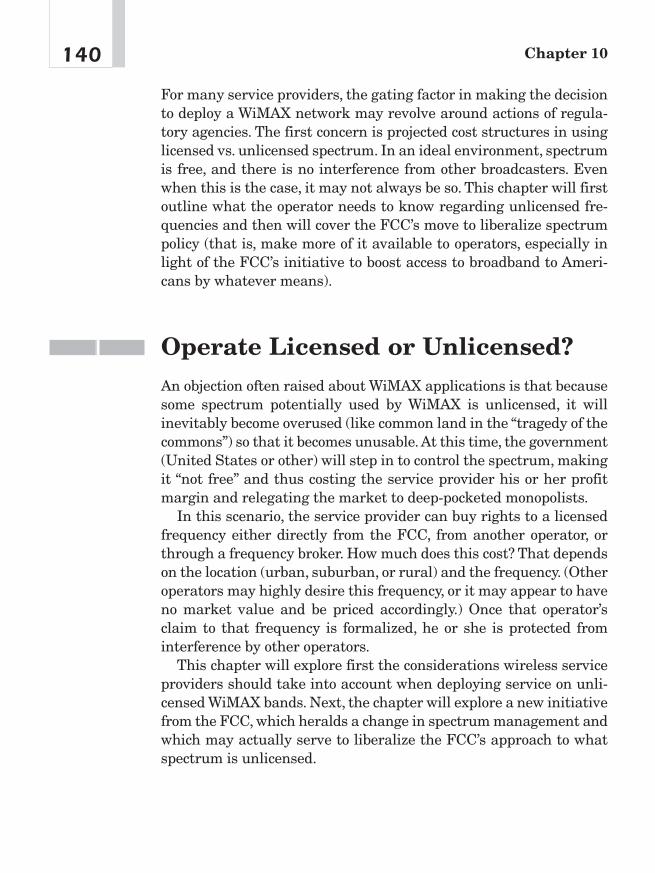
For many service providers, the gating factor in making the decisionto deploy a WiMAX network may revolve around actions of regula-tory agencies. The first concern is projected cost structures in usinglicensed vs. unlicensed spectrum. In an ideal environment, spectrumis free, and there is no interference from other broadcasters. Evenwhen this is the case, it may not always be so. This chapter will firstoutline what the operator needs to know regarding unlicensed fre-quencies and then will cover the FCC’s move to liberalize spectrumpolicy (that is, make more of it available to operators, especially inlight of the FCC’s initiative to boost access to broadband to Ameri-cans by whatever means).
Operate Licensed or Unlicensed?An objection often raised about WiMAX applications is that becausesome spectrum potentially used by WiMAX is unlicensed, it willinevitably become overused (like common land in the “tragedy of thecommons”) so that it becomes unusable.At this time, the government(United States or other) will step in to control the spectrum, makingit “not free” and thus costing the service provider his or her profitmargin and relegating the market to deep-pocketed monopolists.
In this scenario, the service provider can buy rights to a licensedfrequency either directly from the FCC, from another operator, orthrough a frequency broker. How much does this cost? That dependson the location (urban, suburban, or rural) and the frequency. (Otheroperators may highly desire this frequency, or it may appear to haveno market value and be priced accordingly.) Once that operator’sclaim to that frequency is formalized, he or she is protected frominterference by other operators.
This chapter will explore first the considerations wireless serviceproviders should take into account when deploying service on unli-censed WiMAX bands. Next, the chapter will explore a new initiativefrom the FCC, which heralds a change in spectrum management andwhich may actually serve to liberalize the FCC’s approach to whatspectrum is unlicensed.
Chapter 10140
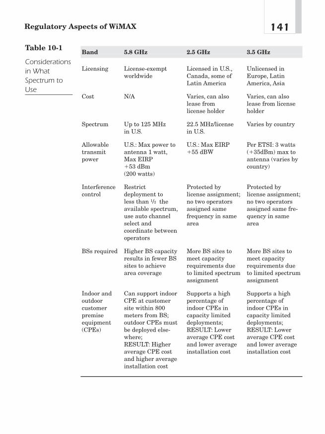
141Regulatory Aspects of WiMAX
Band 5.8 GHz 2.5 GHz 3.5 GHz
Licensing License-exempt Licensed in U.S., Unlicensed in worldwide Canada, some of Europe, Latin
Latin America America, Asia
Cost N/A Varies, can also Varies, can also lease from lease from license license holder holder
Spectrum Up to 125 MHz 22.5 MHz/license Varies by countryin U.S. in U.S.
Allowable U.S.: Max power to U.S.: Max EIRP Per ETSI: 3 watts transmit antenna 1 watt, �55 dBW (�35dBm) max to power Max EIRP antenna (varies by
�53 dBm country)(200 watts)
Interference Restrict Protected by Protected by control deployment to license assignment; license assignment;
less than 1/2 the no two operators no two operators available spectrum, assigned same assigned same fre-use auto channel frequency in same quency in same select and area areacoordinate between operators
BSs required Higher BS capacity More BS sites to More BS sites to results in fewer BS meet capacity meet capacity sites to achieve requirements due requirements due area coverage to limited spectrum to limited spectrum
assignment assignment
Indoor and Can support indoor Supports a high Supports a high outdoor CPE at customer percentage of percentage of customer site within 800 indoor CPEs in indoor CPEs in premise meters from BS; capacity limited capacity limited equipment outdoor CPEs must deployments; deployments;(CPEs) be deployed else- RESULT: Lower RESULT: Lower
where; average CPE cost average CPE cost RESULT: Higher and lower average and lower average average CPE cost installation cost installation costand higher average installation cost
Table 10-1
Considerationsin WhatSpectrum toUse

Finally the chapter will cover an initiative in the U.S. Congress tofree more spectrum for use as broadband wireless Internet applica-tions. If anything, it appears that the United States government isdeveloping a policy to encourage the use of unlicensed spectrum.
Current Regulatory EnvironmentEven though WiMAX can operate in unlicensed spectrum, a serviceprovider must know a number of things in order to stay out of trou-ble with state and federal authorities. The following pages will out-line the most prominent problem areas.
Spectrum is managed by a number of different organizations. Themost visible to the general public is the FCC. The FCC managescivilian, state, and local government usage of the radio spectrum.The FCC regulations are contained in the “Code of Federal Regula-tions, Title 47.”
At the present time, the FCC has very limited resources forenforcement, as the trend for the last couple of decades is deregulat-ing and reducing staffing in the enforcement bureaus. Also, theNational Telecommunications and Information Administration(NTIA) works with the Interdepartmental Radio Advisory Commit-tee (IRAC), which manages federal use of the spectrum.
The following pages offer a brief overview of what a serviceprovider needs to be concerned about when operating in unlicensedspectrum. Tim Pozar of the Bay Area Wireless Users Group providedthis synopsis, based on many years of experience advising friendsand clients as to what they can and cannot do with unlicensed spec-trum. The treatise was originally intended to provide guidelines for802.11 operators, but the law applies equally to 802.16 operators.
Power Limits
Although WiMAX can do 70 Mbps over 30 miles, it must comply withthe power restrictions for that band if it is to operate in an unli-censed frequency. Ideally, a well-engineered path will have just the
Chapter 10142

amount of power required to get from point A to point B with goodreliability. Good engineering will limit the signal to the area beingserved, which has the effect of reducing interference and providing amore efficient use of the spectrum. Using too much power will covermore area than is needed and can potentially interfere with otherusers of the band.
WiMAX 802.16—Its Relationship to FCC Part15, Section 247
If service providers intend to use unlicensed spectrum with theirWiMAX deployment, it would be a good idea to have a thoroughunderstanding of FCC Part 15.
Point-to-Multipoint WiMAX service providers who wish tooperate under this section are allowed up to 30 dBm or 1 watt ofTransmitter Power Output (TPO) with a 6 dBi antenna or 36 dBmor 4 watts effective radiated power over an equivocally isotropicradiated power (EIRP) antenna. The TPO needs to be reduced 1 dBfor every dB of antenna gain over 6 dBi.
Point-to-Point The FCC encourages directional antennas to min-imize interference to other users. The FCC, in fact, is more lenientwith point-to-point links by requiring only the TPO to be reduced by1/3 of a dB instead of a full dB for point-to-multipoint. More specifi-cally, for every 3 dB of antenna gain over a 6 dBi antenna, a WISPneeds to reduce the TPO 1 dB below 1 watt. For example, a 24 dBiantenna is 18 dB over a 6 dBi antenna. This requires lowering a 1watt (30 dBm) transmitter 18/3 or 6 dB to 24 dBm or .25 watt.
802.16—FCC Part 15, Section 407
So what part of Part 15 applies to WiMAX operations in the 5 GHzrange? The following paragraphs will outline the law for this spec-trum.
143Regulatory Aspects of WiMAX

Point-to-Multipoint As described earlier, the U-NII band ischopped into three sections. The “low” band runs from 5.15 GHz to5.25 GHz and has a maximum power of 50 mW (TPO). This band ismeant to be in-building only, as defined by the FCC’s Rules and Reg-ulations (R&R) Part 15.407 (d) and (e):
(d) Any U-NII device that operates in the 5.15–5.25 GHz bandshall use a transmitting antenna that is an integral part ofthe device.
(e) Within the 5.15–5.25 GHz band, U-NII devices will berestricted to indoor operations to reduce any potential forharmful interference to co-channel MSS operations.1
The “middle” band runs from 5.25 GHz to 5.35 GHz, with a maxi-mum power limit of 250 mW. Finally, the “high” band runs from5.725 GHz to 5.825 GHz, with a maximum transmitter power of 1watt and antenna gain of 6 dBi or 36 dBm or 4 watts EIRP.
Point-to-Point The FCC does give some latitude to point-to-pointlinks in 15.407(a)(3). For the 5.725 GHz to 5.825 GHz band, the FCCallows a TPO of 1 watt and up to a 23 dBi gain antenna withoutreducing the TPO 1 dB for every 1 dB of gain over 23 dBi.
15.247(b)(3)(ii) does allow the use of any gain antenna for point-to-point operations without having to reduce the TPO for the 5.725GHz to 5.825 GHz band.
Interference
The raison d’être of the Radio Act of 1927 was to ensure that radiooperators could operate with minimum interference from otherbroadcasters. Part 15 was established to provide a framework forthose operating in the unlicensed spectrum to avoid interfering witheach other.
Description Of course, interference is typically the state of thesignal one is interested in while it’s being destructively overpowered
Chapter 10144
1Tim Pozar, “Regulations Affecting 802.11,” June 6, 2002, www.lns.com/papers/ part15/.

by a signal one is not interested in. The FCC has a specific defini-tion of harmful interference:
Part 15.3(m) Harmful interference.Any emission, radiation or induction that endangers the
functioning of a radio navigation service or of other safety ser-vices or seriously degrades, obstructs or repeatedly interrupts aradio communications service operating in accordance with thischapter.
As there may be other users of this band, interference will bea factor in WiMAX deployments. The 2.4 GHz band is oftenmore congested than the 5.8 GHz band, but both have their co-users. The following subsections will describe the other users ofthis spectrum and what interference mitigation may be possiblefor each.
Devices that Fall into Part 15 (2400—2483 MHz) Table 10-2lists which FCC regulations apply to which frequency bands. Table10-3 lists the spectrum bands of ISM. Unlicensed telecommunica-tions devices like cordless phones, home spy cameras, and FrequencyHopping (FHSS) and Direct Sequence (DSSS) Spread SpectrumLAN transceivers fall into Part 15 (2400—2483 MHz). Operators haveno priority over or parity with any of these users. Any device thatfalls into Part 15 must not cause harmful interference to and mustaccept interference from all licensed and all legally operating Part15 users.
Operators of other licensed and nonlicensed devices can informusers of interference and require that they terminate operation. Thissource needn’t be a Commission representative.
Part 15.5(b) operation of an intentional, unintentional, orincidental radiator is subject to the conditions that no harmfulinterference is caused and that interference must be acceptedthat may be caused by the operation of an authorized radiostation, by another intentional or unintentional radiator, byindustrial, scientific and medical (ISM) equipment, or by anincidental radiator (or basically everything).
145Regulatory Aspects of WiMAX

15.5(c) The operator of a radio frequency device shall berequired to cease operating the device upon notification by acommission representative that the device is causing harmfulinterference. Operation shall not resume until the conditioncausing the harmful interference has been corrected.
Chapter 10146
Part/Use Start GHz End GHz
Part 87 0.4700 10.5000
Part 97 2.3900 2.4500
Part 15 2.4000 2.4830
Fusion Lighting 2.4000 2.4835
Part 18 2.4000 2.5000
Part 80 2.4000 9.6000
ISM—802.11b 2.4010 2.4730
Part 74 2.4500 2.4835
Part 101 2.4500 2.5000
Part 90 2.4500 2.8350
Part 25 5.0910 5.2500
U-NII Low 5.1500 5.2500
U-NII Middle 5.2500 5.3500
Part 97 5.6800 5.9250
U-NII High 5.7250 5.8250
ISM 5.7250 5.8500
Part 18 5.7250 5.8250
Source: Tim Pozar Bay Area Wireless Users Group from FCC sources
Table 10-2
SpectrumAllocation forU-NII and Co-Users
Devices That Fall into the U-NII Band Unlike the 2.4 GHzband, this band does not have overlapping channels. The lower U-NII band has eight 20 MHz wide channels. One can use any of thechannels without interfering with other radios on other channelsthat are within “earshot.” Ideally, it would be good to know whatother Part 15 users are out there.
Industrial, Scientific, and Medical (ISM)—Part 18 This is alsoan unlicensed service. Typical ISM applications are the productionof physical, biological, or chemical effects such as heating, ionizationof gases, mechanical vibrations, hair removal, and acceleration ofcharged particles. Users are ultrasonic devices, such as jewelrycleaners, ultrasonic humidifiers, and microwave ovens; medicaldevices, such as diathermy equipment and magnetic resonance
147Regulatory Aspects of WiMAX
Channel Bottom (GHz) Center (GHz) Top (GHz)
1 2.401 2.412 2.423
2 2.406 2.417 2.428
3 2.411 2.422 2.433
4 2.416 2.427 2.438
5 2.421 2.432 2.443
6 2.426 2.437 2.448
7 2.431 2.442 2.453
8 2.436 2.447 2.458
9 2.441 2.452 2.463
10 2.446 2.457 2.468
11 2.451 2.462 2.473
Source: Tim Pozar Bay Area Wireless Users Group from FCC sources
Table 10-3
United StatesISM ChannelAllocations
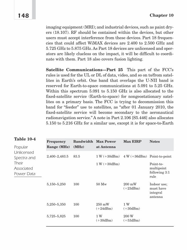
imaging equipment (MRI); and industrial devices, such as paint dry-ers (18.107). RF should be contained within the devices, but otherusers must accept interference from these devices. Part 18 frequen-cies that could affect WiMAX devices are 2.400 to 2.500 GHz and5.725 GHz to 5.875 GHz. As Part 18 devices are unlicensed and oper-ators are likely clueless on the impact, it will be difficult to coordi-nate with them. Part 18 also covers fusion lighting.
Satellite Communications—Part 25 This part of the FCC’srules is used for the UL or DL of data, video, and so on to/from satel-lites in Earth’s orbit. One band that overlaps the U-NII band isreserved for Earth-to-space communications at 5.091 to 5.25 GHz.Within this spectrum 5.091 to 5.150 GHz is also allocated to thefixed-satellite service (Earth-to-space) for nongeostationary satel-lites on a primary basis. The FCC is trying to decommission thisband for “feeder” use to satellites, as “after 01 January 2010, thefixed-satellite service will become secondary to the aeronauticalradionavigation service.” A note in Part 2.106 [S5.446] also allocates5.150 to 5.216 GHz for a similar use, except it is for space-to-Earth
Chapter 10148
Frequency Bandwidth Max Power Max EIRP Notes
Range (MHz) (MHz) at Antenna
2,400—2,483.5 83.5 1 W (�30dBm) 4 W (�36dBm) Point-to-point
1 W (�30dBm) Point-to-multipoint following 3:1 rule
5,150—5,250 100 50 Mw 200 mW Indoor use;(�23dBm) must have
integral antenna
5,250—5,350 100 250 mW 1 W (�24dBm) (�30dBm)
5,725—5,825 100 1 W 200 W (�30dBm) (�53dBm)
Table 10-4
PopularUnlicensedSpectra andTheirAssociatedPower Data

communications. There is a higher chance of interfering with theseinstallations, as Earth stations are dealing with very low signal lev-els from distance satellites.
Broadcast Auxiliary—Part 74 Normally the traffic is electronicnews gathering (ENG) video links going back to studios or televisiontransmitters. These remote vehicles, such as helicopters and trucks,need to be licensed. Only Part 74 eligibles, such as TV stations, net-works, and so on, can hold these licenses (74.600). Typically thesetransmitters are scattered all around an area, as TV remote truckscan go anywhere. This can cause interference to WiMAX gear, suchas BS deployed with omnidirectional antennas servicing an area.Also the receive points for ENG are often mountaintops and towers.Depending on how WiMAX BSs are deployed at these same loca-tions, they could cause interference to these links. Wireless providersshould consider contacting a local frequency coordinator for Part 74frequencies that would be affected. ENG frequencies that overlapISM devices are 2.450 to 2.467 GHz (channel A08) and 2.467 to2.4835 GHz (channel A09), (Part 74.602).
Land Mobile Radio Services—Part 90 For subpart C of thispart, a user can be anyone engaged in a commercial activity. Theycan use from 2.450 to 2.835 GHz but can only license 2.450 to 2.483GHz. Users in subpart B would be local governments, including orga-nizations such as law enforcement agencies, fire departments, andso on. Some uses may be video DLs for flying platforms such as heli-copters, aka terrestrial surveillance. Depending on the commercialor government agency, coordination goes through different groupslike Association of Public Safety Communications Officials (APCO).Consider going to their conferences. Also, try to network with engi-neering companies that the government outsources to for their fre-quency coordination.
Amateur Radio—Part 97 Amateur radio frequencies that over-lap ISM are 2.390 to 2.450 GHz and 5.650 to 5.925 GHz for U-NII.They are primary from 2.402 to 2.417 GHz and secondary at 2.400to 2.402 GHz. There is a Notice of Proposed Rule Making (NPRM)with the FCC to change the 2.400 to 2.402 GHz to primary.
149Regulatory Aspects of WiMAX
Fixed Microwave Services—Part 101 Users are known as localtelevision transmission service (LTTS) and private operational fixedpoint-to-point microwave service (POFS). This band is used to trans-port video. Users are allocated from 2.450 to 2.500 GHz.
Federal Usage (NTIA/IRAC) The federal government uses thisband for radiolocation or radionavigation. Several warnings in theFCC’s Rules and Regulations disclose this fact. In the case of802.16b, a note in the rules warns:
15.247(h) Spread spectrum systems are sharing these bands ona noninterference basis with systems supporting critical gov-ernment requirements that have been allocated the usage ofthese bands, secondary only to ISM equipment operated underthe provisions of Part 18 of this chapter. Many of these govern-ment systems are airborne radiolocation systems that emit ahigh EIRP, which can cause interference to other users.
In the case of U-NII, the FCC has a note in Part 15.407 statingthat:
Commission strongly recommends that parties employing U-NII devices to provide critical communications services shoulddetermine if there are any nearby government radar systemsthat could affect their operation.
Laws on Antennas and Towers
Many a local zoning board have found telecommunications towers tobe considered “unsightly.” How is an operator to deal with such alle-gations?
FCC Preemption of Local Law The installation of antennasmay run counter to local ordinances and homeowner agreementsthat would prevent installations. Thanks to the Satellite Broad-casting and Communications Association (SBCA), who lobbied theFCC, the FCC has stepped in and overruled these ordinances andagreements.
Chapter 10150
This ruling from the FCC should only apply to broadcast signalssuch as TV, DBS, or MMDS. It could be argued that the provision forMMDS could cover wireless data deployment.
Height Limitations The placement of towers and other broad-cast-related equipment could spark any series of “federal cases” orother lengthy disputes regarding which government has what juris-diction on broadcasting equipment.
Local Ordinances Most if not all cities regulate the construction oftowers. There are maximum height zoning regulations regarding theantenna/tower (residential or commercial), construction, and aes-thetics (for example, what color, how hidden).
FAA and the FCC Tower Registration The FAA is very concernedabout objects that airplanes might bump into. Part 17.7(a) of theFCC R&R describes “any construction or alteration of more than60.96 meters (200 feet) in height above ground level at its site.”2
New Unlicensed Frequencies
In June 2004, the FCC had recently approved plans to improve themanagement of a block of radio spectrum, 2.495 GHz to 2.690 GHz,to ease the way for the wider adoption of wireless broadband access.3
Working its way through the U.S. Congress is the Jumpstart Broad-band Bill (aka Boxer-Allen Bill—U.S. Senate), which would add 255MHz in the 5 GHz unlicensed band. The bill is part of a wider moveto bolster wireless broadband as a “third leg” to the broadband stoolof cable and DSL (cable TV and telephone companies).4
151Regulatory Aspects of WiMAX
2Tim Pozar, “Regulations Affecting 802.16 Deployment,” white paper from Bay AreaWireless Users Group, pp. 2—7, 10—11, www.lns.com/papers/part15/.3Richard Shim, “FCC Cleans Up Spectrum for Wireless Broadband,” June 10, 2004,CNET, http://news.com.com/FCC�cleans�up�spectrum�for�wireless�broadband/2100-1034_3-5230766.html?tag�st.rc.targ_mb.4Roy Mark, “Senators Aim to Wirelessly Jumpstart Broadband,” November 20, 2002,http://siliconvalley.internet.com/news/article.php/1545891.

In March 2005, the FCC issued an order to open the 3.650—3.7 GHzspectrum for wireless broadband services. The licensing scheme thatthe FCC adopts for this band will provide an opportunity for theintroduction of a variety of new wireless broadband services andtechnologies, such as WiMAX. Additionally, the actions the FCCtakes herein for the 3,650 MHz band will allow further deploymentof advanced telecommunications services and technologies to allAmericans, especially in the rural heartland, thus promoting theobjectives of Section 706 of the Telecommunications Act of 1996.5 Thechief caveat of this order is that these transmissions cannot occurnear satellite ground stations listed in the order.
Unlicensed Frequencies Summary
Although frequencies in the ISM and U-NII bands are unlicensed(that is, free), they are not without restrictions. Power restrictionsmay limit the potential for a WiMAX operator to project the fullpotential of the platform to transmit a given bandwidth over a givendistance. Operators considering using WiMAX on unlicensed spec-trum should perform a thorough site survey to determine potentialconflicts with the law and fellow broadcasters for the given location,frequency, and power level on which they intend to operate.
The FCC New Spectrum PolicyThe American spectrum management regime is approximately 90years old. In the opinion of former FCC chairman Michael Powell, itneeds a hard look and a new direction. Historically, spectrum policyhas four underlying core assumptions: (1) unregulated radio inter-ference will lead to chaos; (2) spectrum is scarce; (3) governmentcommand and control of the scarce spectrum resource is the onlyway chaos can be avoided; and (4) the public interest centers on gov-ernment choosing the highest and best use of the spectrum.
Chapter 10152
5Federal Communications Commission, “Report and Order of Opinion and Order 05-56,” March 16, 2005, p. 2.
Four Problem Areas in SpectrumManagement and Their Solutions
There are four problem areas the FCC will have to work its waythrough in order to liberalize spectrum policy. The payoff is a morefunctional spectrum policy to meet the needs of telecommunicationsusers.
Interference—The Problem From 1927 until today, interferenceprotection has always been at the core of federal regulators’ spec-trum mission. The Radio Act of 1927 empowered the Federal RadioCommission to address interference concerns. Although interferenceprotection remains essential to our mission, interference rules thatare too strict limit users’ ability to offer new services; whereas rulesthat are too lax may harm existing services. I believe the Commis-sion should continuously examine whether there are market or tech-nological solutions that can—in the long run—replace or supplementpure regulatory solutions to interference.
The FCC’s current interference rules were typically developedbased on the expected nature of a single service’s technical charac-teristics in a given band.The rules for most services include limits onpower and emissions from transmitters. Each time the old serviceneeds to evolve with the demands of its users, the licensee has tocome back to the Commission for relief from the original rules. Thisprocess is not only inefficient; it can stymie innovation.
Due to the complexity of interference issues and the RF environ-ment, interference protection solutions may be largely technologydriven. Interference is not solely caused by transmitters, whichmany seem to assume, and on which our regulations are almostexclusively based. Instead, interference is often more a product ofreceivers; that is, receivers are too dumb or too sensitive or too cheapto filter out unwanted signals. Yet, the FCC’s decades-old rules havegenerally ignored receivers. Emerging communications technologiesare becoming more tolerant of interference through sensory andadaptive capabilities in receivers. That is, receivers can “sense” whattype of noise or interference or other signals are operating on a givenchannel and then “adapt,” so that they transmit on a clear channelthat allows them to be heard.
153Regulatory Aspects of WiMAX
Both the complexity of the interference task—and the remarkableability of technology (rather than regulation) to respond to it—aremost clearly demonstrated by the recent success of unlicensed oper-ations. According to the Consumer Electronics Association, a com-plex variety of unlicensed devices—including garage and car dooropeners, baby monitors, family radios, wireless headphones, and mil-lions of wireless Internet access devices using Wi-Fi technologies—isalready in common use. Yet despite the sheer volume of devices andtheir disparate uses, manufacturers have developed technology thatallows receivers to sift through the noise to find the desired signal.
Interference—The Solution Legal approaches to interferencemitigation may often be the easier solution. Legislation sorely needsto be updated to accommodate for advances in technology.
Interference Protection The Interference Protection Working Group(Working Group) of the FCC’s Spectrum Policy Task Force recom-mended that the FCC should consider using the Interference Tem-perature metric as a means of quantifying and managing inter-ference. As introduced in this report, interference temperature is ameasure of the RF power available at a receiving antenna to bedelivered to a receiver—power generated by other emitters and noisesources. More specifically, it is the temperature equivalent of the RFpower available at a receiving antenna per unit bandwidth, mea-sured in units of degrees Kelvin. As conceptualized by the WorkingGroup, the terms “interference temperature” and “antenna temper-ature” are synonymous. The term “interference temperature” is moredescriptive for interference management. For a technical descriptionof interference, see Chapter 6.
Like other representations of radio signals, instantaneous valuesof interference temperature would vary with time and, thus, wouldneed to be treated statistically. The Working Group envisions thatinterference “thermometers” could continuously monitor particularfrequency bands, measure and record interference temperature val-ues, and compute appropriate aggregate value(s). These real-timevalues could govern the operation of nearby RF emitters. Measure-ment devices could be designed with the option to include or excludethe on-channel energy contributions of particular signals with
Chapter 10154
known characteristics such as the emissions of users in geographicareas and bands where spectrum is assigned to licensees for exclu-sive use.
The FCC could use the interference temperature metric to setmaximum acceptable levels of interference, thus establishing aworst case environment in which a receiver would operate. Interfer-ence temperature thresholds could thus be used, where appropriate,to define interference protection rights.
The time has come to consider an entirely new paradigm for inter-ference protection. A more forward-looking approach requires thatthere be a clear quantitative application of what is acceptable inter-ference for both license holders and the devices that can cause inter-ference. Transmitters would be required to ensure that theinterference level—or interference temperature—is not exceeded.Receivers would be required to tolerate an interference level.
Rather than simply saying a transmitter cannot exceed a certainpower, the industry instead would utilize receiver standards andnew technologies to ensure that communication occurs withoutinterference and that the spectrum resource is fully utilized. So, forexample, perhaps services in rural areas could utilize higher powerlevels because the adjacent bands are less congested, thereforedecreasing the need for interference protection.6
From a simplistic and physical standpoint, any transmission facil-ity requires a transmitter, a medium for transmission, and areceiver. Focus on receiver characteristics has not been high in pastspectrum-use concerns; hence, a shift in focus is in order. The Work-ing Group believes that receiver reception factors, including sensi-tivity, selectivity, and interference tolerance, need to play aprominent role in spectrum policy.7
Spectrum Scarcity—The Problem Much of the Commission’sspectrum policy was driven by the assumption that there is neverenough for those who want it. Under this view, spectrum is so scarce
155Regulatory Aspects of WiMAX
6Michael Powell, “Broadband Migration—New Directions in Wireless Policy,” speech toSilicon Flatirons Conference, University of Colorado, Boulder, October 30, 2002.7Federal Communications Commission Spectrum Policy Task Force, “Report of theInterference Protection Working Group,” November 15, 2002, p. 25.
that government, rather than market forces, must determine whogets to use the spectrum and for what. The spectrum scarcity argu-ment shaped the Supreme Court’s Red Lion decision, which gave theCommission broad discretion to regulate broadcast media on thepremise that spectrum is a unique and scarce resource. Indeed mostassumptions that underlie the current spectrum model derive fromtraditional radio broadcasting and are oblivious to wireless broad-band Internet applications.
The Commission has recently conducted a series of tests to assessactual spectrum congestion in certain locales. These tests, whichwere conducted by the Commission’s Enforcement Bureau in coop-eration with the Task Force, measured use of the spectrum at fivemajor cities in the United States. The results showed that althoughsome bands were heavily used, others either were not used or wereused only part of the time. It appeared that these “holes” in band-width or time could be used to provide significant increases in com-munication capacity without impacting current users through use ofnew technologies. These results call into question the traditionalassumptions about congestion. Indeed, most of spectrum is appar-ently not in use most of the time.
Today’s digital migration means that more and more data can betransmitted in less and less bandwidth. Not only is less bandwidthused, but innovative technologies, like software-defined radio andadaptive transmitters, can bring additional spectrum into the pool ofspectrum available for use.
Spectrum Scarcity—The Solution In analyzing the current useof spectrum, the Task Force took a unique approach: For the firsttime, they looked at the entire spectrum, not just one band at a time.This review prompted a major insight—there is a substantialamount of white space out there that is not being used by anybody.The ramifications of this insight are significant. Although spectrumscarcity is a problem in some bands some of the time, the larger prob-lem is spectrum access: or how to get to and use those many areasof the spectrum that are either underutilized or not used at all.
One way the Commission can take advantage of this white spaceis by facilitating access in the time dimension. Since the beginning ofspectrum policy, the government has parceled this resource in fre-
Chapter 10156

quency and in space. The FCC historically permitted use in a partic-ular band over a particular geographic region, often with an expec-tation of perpetual use. The FCC should also look at time as anadditional dimension for spectrum policy. How well could society usethis resource if FCC policies fostered access in frequency, space, andtime?
Technology has facilitated access to spectrum in the time dimen-sion, which will lead to more efficient use of the spectrum resource.For example, a software-defined radio may allow licensees to dynam-ically “rent” certain spectrum bands when they are not in use byother licensees. Perhaps a mobile wireless service provider withsoftware-defined phones will lease a local business’s channels duringthe hours the business is closed. Similarly sensory and adaptivedevices may be able to “find” spectrum open space and utilize it untilthe licensee needs those rights for its own use. In a commercial con-text, secondary markets can provide a mechanism for licensees tocreate and provide opportunities for new services in distinct slices oftime. By adding another meaningful dimension, spectrum policy canmove closer to facilitating consistent availability of spectrum andfurther diminish the scarcity rationale for intrusive governmentaction.
Government Command and Control—The Problem The the-ory back in the 1930s was that only government could be trusted tomanage this scarce resource and ensure that no one got too much ofit. Unfortunately, spectrum policy is still predominantly a commandand control process that requires government officials—instead ofspectrum users—to determine the best use for spectrum and makevalue judgments about proposed, and often overhyped, uses andtechnologies. It is an entirely reactive and too easily politicizedprocess.
In the last 20 years, two alternative, very flexible models to com-mand and control the spectrum have developed. The first is theexclusive use or quasi-property rights model. This model providesexclusive, licensed rights to flexible-use frequencies, subject only tolimitations on harmful interference. These rights are freely trans-ferable. The second is the commons or open access model. This modelallows users to share frequencies on an unlicensed basis with usage
157Regulatory Aspects of WiMAX

rights that are governed by technical standards but without anyright to protection from interference. The Commission has employedboth models with significant success. Licensees in mobile wirelessservices have enjoyed quasi-property right interests in theirlicensees and transformed the communications landscape as aresult. In contrast, the unlicensed bands employ a commons modeland have enjoyed tremendous success as hotbeds of innovation.
Government Command and Control of the Spectrum—TheSolution Historically the Commission often limited flexibility viacommand and control regulatory restrictions on which serviceslicensees could provide and who could provide them. Any spectrumusers that wanted to change the power of their transmitter, thenature of their service, or the size of an antenna had to come to theCommission to ask for permission, wait the corresponding period oftime, and only then, if relief was granted, modify the service. Today’smarketplace demands that the FCC provide license holders withgreater flexibility to respond to consumer wants, market realities,and national needs without first having to ask for the FCC’s per-mission. License holders should be granted the maximum flexibilityto use—or allow others to use—the spectrum, within technical con-straints, to provide any services demanded by the public. With thisflexibility, service providers can be expected to move spectrumquickly to its highest and best use.
Public Interest—The Problem The fourth and final element oftraditional spectrum policy is the public interest standard. Thephrase (or something similar) “public interest, convenience, or neces-sity” was a part of the Radio Act of 1927 and likely came from otherutility regulation statutes. The standard was largely a response tothe interference and scarcity concerns that were created in theabsence of such a discretionary standard in the 1912 Act. This “pub-lic interest, convenience, and necessity” became a standard by whichto judge between competing applicants for a scarce resource—and atool for ensuring interference did not occur.The public interest underthe command and control model often decided which companies orgovernment entities would have access to the spectrum resource. Atthat time, spectrum was not largely a consumer resource but, rather,
Chapter 10158
was accessed by a relatively select few. However, Congress wisely didnot create a static public interest standard for spectrum allocationand management.
Serving the Public Interest in Spectrum Policy—The Solu-tion The FCC should develop policies that avoid interference rulesthat are barriers to entry, that assume a particular proponent’s busi-ness model or technology, and that take the place of marketplace ortechnical solutions. Such a policy must embody what we have seenbenefit the public in every other area of consumer goods and ser-vices: choice through competition and limited but necessary govern-ment intervention into the marketplace to protect such interests asaccess to people with disabilities, public health, safety, and welfare.
Recent Statements from the FCCon Broadband and Spectrum PolicyA recurring objection to WiMAX is pessimism toward what role reg-ulators will take: “Won’t ‘they’ take away free spectrum and prop upthe monopolistic incumbents?” Indications from the FCC seem topoint in the opposite direction. Below are recent comments by formerFCC chair Michael Powell. Readers are invited to make their ownconclusions as to whether this will be enough remedy in time tolaunch the WiMAX revolution.
Earlier this year [2004], I [FCC chair Michael Powell] createdthe Wireless Broadband Access Task Force to review ourwireless broadband policies and to identify areas whereadditional Commission action, or restraint, could facilitatefurther deployment. The task force has identified several keyissues in this regard.
First, we need more broadband spectrum. In this era ofincreasingly intensive spectrum use, we must continue to striveto provide opportunities for new and enhanced spectrum-basedservices. I applaud the Administration’s decision to undertake acomprehensive review of spectrum policy. The reports of thePresident’s Spectrum Policy Initiative offer much food for
159Regulatory Aspects of WiMAX

thought about these timely issues. The significant spectrumreforms that we at the FCC have worked so hard to identify andimplement over the last two years, coupled with the results ofthe President’s Spectrum Policy Initiative, will help enable us tocraft policies that will facilitate delivery of wireless broadbandservices to the American people.
The FCC is moving aggressively to put valuable spectrum onthe market through auctions. In January, the Commission willauction over 200 broadband PCS C and F block licenses. Inaddition, we are working collaboratively with our colleagues atNTIA to move forward expeditiously to an auction of spectrumat 2 GHz for advanced wireless services. We also greatly appre-ciate Congress’ efforts to craft the Spectrum Relocation TrustFund to ensure that the relocation of military operations thatcurrently use this spectrum can be adequately funded with theproceeds of this auction. I urge Congress to pass this legislationas quickly as possible.
A second key conclusion is that we need greater access to thespectrum that is in the market. One significant finding of ourtask force effort was that most of the spectrum is not being usedmost of the time.This means that rather than scarcity being theproblem, the real problem is how to get access to spectrum. Webelieve technology is going to usher in the possibility of muchmore dynamic use of frequencies without unacceptable inter-ference.
At the federal level, we must push for procompetitive, market-based policies for all broadband technologies in order to allowthe various platforms to compete freely and fully. Wireless,cable, DSL, satellite, and power lines should compete where itmakes sense for them to compete and become integrated wherethey are complementary. In such a market, consumers benefitgreatly, as the market itself can change to meet consumers’needs far faster than regulators could act to address consumers’concerns.8
Chapter 10160
8Michael K. Powell, “The Wireless Broadband Express” (remarks, CTIA Wireless I.T.& Entertainment Convention, San Francisco, October 26, 2004).
Our unlicensed rules have been a hotbed for wirelessbroadband innovation—spawning new industries like your ownand encouraging significant capital investment. It is estimatedthat by next year, sales of wireless networking equipment willexceed $5 billion. Our regulatory flexibility in this area hashelped to enable this thriving industry.
We continue to look for more ways to encourage growth ofunlicensed wireless broadband services. Last year, we made anadditional 255 MHz of spectrum available in the 5 GHz regionof the spectrum—adding a sizable chunk of spectrum to thatalready available for unlicensed devices. We also madespectrum available in the upper reaches of the spectrum—above 70 GHz—on an unlicensed and very lightly licensedbasis. Technologies that use this new spectrum frontier arerapidly maturing and new services are on the horizon. We arealso in the process of considering additional spectrum bands foruse by unlicensed devices—the so-called spectrum “whitespaces” between the channels assigned for TV broadcastservices and 50 MHz of spectrum in the 3,650 MHz band.9
ConclusionThis chapter outlines the current regulatory regime for WiMAXoperators. The chapter answers the objection that there is too littlespectrum available for a mass-market deployment of WiMAX.Recent studies and pronouncements by the FCC and members of theU.S. Senate indicate support for reforming the spectrum policy inpromoting the deployment of WiMAX and its related technologies asan alternative source of residential broadband to cable TV and DSL.
161Regulatory Aspects of WiMAX
9Michael K. Powell, “WISPs: Bringing the Benefits of Broadband to Rural America”(remarks as prepared for delivery at WISPCON, Las Vegas, NV, October 27, 2004).

This page intentionally left blank
How to Dismantle aPSTN: The
Business Casefor WiMAX
CHAPTER 1111
Copyright © 2005 by The McGraw-Hill Companies, Inc. Click here for terms of use.
OverviewThe preceding ten chapters have discussed the technology of WiMAXand a number of potential applications. The purpose of this chapteris to determine the big “so what?!” of WiMAX. This chapter willexamine the WiMAX applications that exist and how they can poten-tially disrupt existing service and power structures in the telecom-munications industry.
Immediate Markets
Where can WiMAX be applied today to save money on both operat-ing expenses (OPEX) and capital expenditures (CAPEX)? The fol-lowing sections describe where and how WiMAX can save money andopen new markets.
Local Loop Bypass Many businesses in the small-to-mediumenterprise (SME) market pay dearly every month for what is billedas “local loop,” the charge for transporting data over copper wire tothe customer’s premise. This charge applies to the firm’s data T1(1.54 Mbps) or voice T1 for circuit-switched voice. This cost is oftenhundreds of dollars per month per T1. For DS3s (45 Mbps) the costper month may be in the thousands of dollars. The farther the cus-tomer’s premises are from the telephone company’s central office, thegreater the cost. By adopting WiMAX as a local loop bypass, busi-nesses can save money two ways:
1. They can eliminate or greatly reduce the monthly local loop feeby getting their T1 or DS3 data from a WiMAX-enabled serviceprovider.
2. They can eliminate or greatly reduce the monthly cost on thelocal loop charge for their voice T1 service by switching to aVoIP service provider and utilizing WiMAX as an alternative tothe local loop copper.
Figure 11-1 illustrates bypassing local loop charges by using WiMAXas a local loop alternative. Figure 11-2 details savings on local loop
Chapter 11164

charges when utilizing WiMAX as a VoIP delivery alternative to thetelephone company’s circuit-switched telephone service.
Residential and SOHO High-Speed Internet Access Todaythis market segment is primarily dependent on the availability ofDSL or cable. In some areas the available services may not meet cus-tomer expectations for performance or reliability and/or are tooexpensive. In many rural areas, residential customers are limited tolow-speed dial-up services. In developing countries, many regionshave no available means for Internet access. The analysis will showthat the WiMAX technology will enable an operator to economicallyaddress this market segment and have a winning business caseunder a variety of demographic conditions.
Small and Medium Business This market segment is very oftenunderserved in areas other than highly competitive urban environ-ments. The WiMAX technology can cost-effectively meet the require-ments of small and medium size businesses in low-densityenvironments and can also provide a cost-effective alternative inurban areas competing with DSL and leased line services.
165How to Dismantle a PSTN: The Business Case for WiMAX
PSTN Bypass of T1–DS3 Local LoopCharges
Office Building
Wireless T1 or DS3
Fiber POP/Data Center/"Lit" building in metro area
PSTN
IP cloud
Figure 11-1WiMAX is analternative tothe telephonecompany’s localloop charges ondata circuits andcan save theenterprise onmonthly localloop charges.
Wi-Fi Hot Spot Backhaul Wi-Fi hot spots are being installedworldwide at a rapid pace. One of the obstacles for continued hotspot growth, however, is the availability of high capacity, cost-effective backhaul solutions. This application can also be addressedwith the WiMAX technology. And with nomadic capability, WiMAXcan also fill in the coverage gaps between Wi-Fi hot spot coverageareas. Figure 11-3 illustrates WiMAX as a backhaul to existing Wi-Fi networks.
Secondary Markets
The following applications are not included in the business caseanalysis. Nevertheless, they are worthy of mention, as they repre-sent additional potential revenue sources for the wireless operator.
Cellular Backhaul In the United States, the majority of backhaulis done by leasing T1 services from incumbent wire-line operators.With the WiMAX technology, cellular operators will have the oppor-tunity to decrease their independence on backhaul facilities leasedfrom their competitors. Outside the United States, the use of point-
Chapter 11166
WiMAX Subscriber Unit WiMAX Subscriber Unit
VolP Gateway VolP Gateway
PBX Switch PBX Switch
POTS Phone POTS Phone
Antenna AntennaPSTN
Figure 11-2Savings on localloop chargeswhen WiMAX isused as a VoIPdeliveryalternative
to-point microwave is more prevalent for mobile backhaul, butWiMAX can still play a role in enabling mobile operators to cost-effectively increase backhaul capacity using WiMAX as an overlaynetwork. This overlay approach will enable mobile operators to addthe capacity required to support the wide range of new mobile ser-vices they plan to offer without the risk of disrupting existing ser-vices. In many cases, this application will be best addressed throughthe use of WiMAX-based point-to-point links sharing the PMP infra-structure.
Public Safety Services and Private Networks Support fornomadic services and the ability to provide ubiquitous coverage in ametropolitan area provide a tool for law enforcement, fire protection,and other public safety organizations, enabling them to maintaincritical communications under a variety of adverse conditions. Pri-vate networks for industrial complexes, universities, and other cam-pus type environments also represent a potential businessopportunity for WiMAX.
Demographics
Demographics play a key role in determining the business viabilityof any telecommunications network. Traditionally, demographicregions are divided into urban, suburban, and rural areas. In ouranalysis, a fourth area, called exurban, has been added. Exurban
167How to Dismantle a PSTN: The Business Case for WiMAX
WiMAX base station
Wi-Fi base station
WiMAX backhaul
Wi-Fi subscribers
Figure 11-3WiMAX asbackhaulsupporting Wi-Finetworks

areas are primarily residential and compared to suburban areas arefurther from the urban center with lower household densities. DSLavailability is limited because of the distance between the end-userand the switching center, and cable, in many cases, is simply tooexpensive.
Rural areas for the purpose of the business case analysis aredefined as small cities or towns that are located far from a metro-politan area. Customer densities can be fairly high in these areas,but they tend to be underserved because of their remote location.Table 11-1 summarizes the characteristics that will generally beencountered in each of the four geographical areas under considera-tion for a new wireless service provider.
Services
A description of the services used in the business case with theassumed first year annual revenues per user (ARPUs) follows. TheseARPUs are competitive with or below current cable, DSL, and leased
Chapter 11168
Area Characteristics
Urban ■ highest density potential WiMAX subscribers
■ many multiple tenant office and residential buildings
■ smaller WiMAX cell sizes to meet capacity requirements
■ strong competition driven by market size and availabil-ity of alternate access technologies
This competitive environment leads to
■ lower market penetration
■ higher marketing and sales expense
Other considerations include
■ licensed spectrum a good idea: minimize potential forinterference
Table 11-1
DemographicMarket forWiMAX
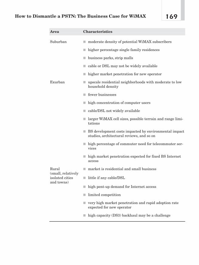
169How to Dismantle a PSTN: The Business Case for WiMAX
Area Characteristics
Suburban ■ moderate density of potential WiMAX subscribers
■ higher percentage single family residences
■ business parks, strip malls
■ cable or DSL may not be widely available
■ higher market penetration for new operator
Exurban ■ upscale residential neighborhoods with moderate to lowhousehold density
■ fewer businesses
■ high concentration of computer users
■ cable/DSL not widely available
■ larger WiMAX cell sizes, possible terrain and range limi-tations
■ BS development costs impacted by environmental impactstudies, architectural reviews, and so on
■ high percentage of commuter need for telecommuter ser-vices
■ high market penetration expected for fixed BS Internetaccess
Rural ■ market is residential and small business(small, relatively isolated cities ■ little if any cable/DSLand towns)
■ high pent-up demand for Internet access
■ limited competition
■ very high market penetration and rapid adoption rateexpected for new operator
■ high capacity (DS3) backhaul may be a challenge

line services in most developed countries. For the business caseanalysis, the ARPUs are assumed to drop 5 percent per year afterthe first year. Wire-line operators generally offer several types of ser-vices for SME, but for the sake of simplicity, only two service levelshave been assumed for this analysis.
In addition to high-speed Internet access, it is assumed the oper-ator will also offer voice services to residential and SME customers.Other revenue sources include one-time activation fees and equip-ment rental fees for operator-supplied customer premise equipment.These fees are assumed to stay constant over the business caseperiod. Regulator imposed taxes and tariffs are not included in theanalysis because these costs are generally passed through to theend-customer and will, therefore, have little or no impact on the busi-ness case.
Frequency Band Alternatives
A key decision regarding spectrum choice is whether to use licensedor unlicensed spectrum. The use of licensed spectrum has the obvi-ous advantage of providing protection against interference fromother wireless operators. The disadvantage is dealing with thelicensing process. This process varies depending on local regulation.It can be very simple and quick or complex and lengthy, and in coun-tries where auctions are used, it can be expensive in highly sought-after regions. The use of unlicensed spectrum gives the wirelessoperator the advantage of being able to deploy immediately but runsthe risk of interference from neighboring wireless operators in thefuture. In general, our feeling is that the use of licensed spectrum isdesirable in major metropolitan areas where multiple wireless oper-ators are more likely.
License-exempt spectrum, on the other hand, is often a good choicein rural areas where fewer operators are likely to exist. In theseareas, interference mitigation is easily accomplished through fre-quency coordination between the operators. A good practice whendeploying with unlicensed spectrum is to size hubs so that no morethan half the available band is used. This enables the use of auto-
Chapter 11170
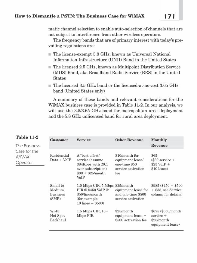
171How to Dismantle a PSTN: The Business Case for WiMAX
matic channel selection to enable auto-selection of channels that arenot subject to interference from other wireless operators.
The frequency bands that are of primary interest with today’s pre-vailing regulations are:
■ The license-exempt 5.8 GHz, known as Universal NationalInformation Infrastructure (UNII) Band in the United States
■ The licensed 2.5 GHz, known as Multipoint Distribution Service(MDS) Band, aka Broadband Radio Service (BRS) in the UnitedStates
■ The licensed 3.5 GHz band or the licensed-at-no-cost 3.65 GHzband (United States only)
A summary of these bands and relevant considerations for theWiMAX business case is provided in Table 11-2. In our analysis, wewill use the 3.5/3.65 GHz band for metropolitan area deploymentand the 5.8 GHz unlicensed band for rural area deployment.
Customer Service Other Revenue Monthly
Revenue
Residential A “best effort” $10/month for $65Data � VoIP service (assume equipment lease/ ($30 service �
384Kbps with 20:1 one-time $50 $25 VoIP �over-subscription) service activation $10 lease)$30 � $25/month feeVoIP
Small to 1.0 Mbps CIR, 5 Mbps $35/month $985 ($450 � $500 Medium PIR @ $450 VoIP @ equipment lease fee � $35, see Service Business $50/line/month and one-time $500 column for details)(SMB) (for example, service activation
10 lines � $500)
Wi-Fi 1.5 Mbps CIR, 10� $25/month $675 ($650/month Hot Spot Mbps PIR equipment lease � service �Backhaul $500 activation fee $25/month
equipment lease)
Table 11-2
The BusinessCase for theWiMAXOperator
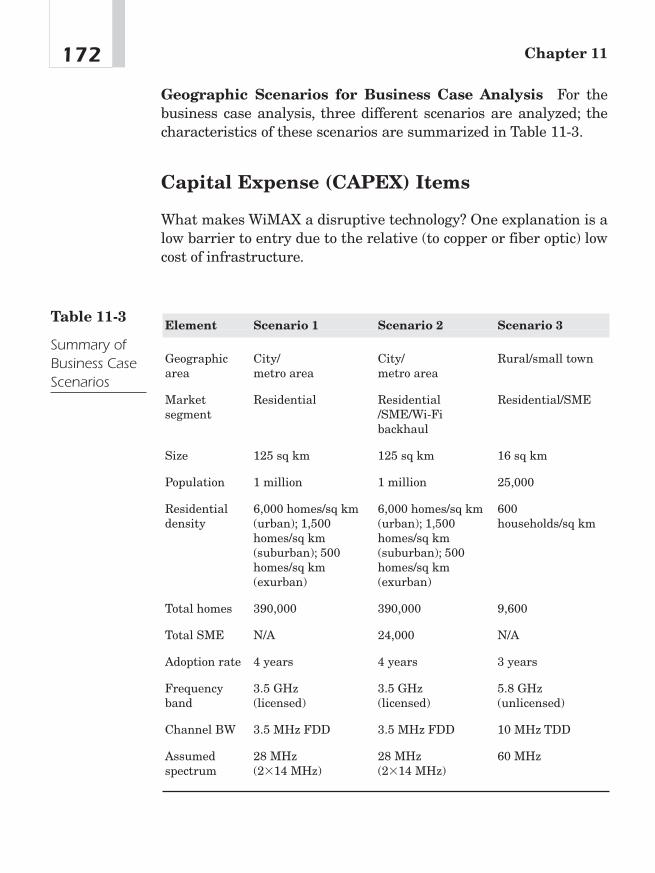
Geographic Scenarios for Business Case Analysis For thebusiness case analysis, three different scenarios are analyzed; thecharacteristics of these scenarios are summarized in Table 11-3.
Capital Expense (CAPEX) Items
What makes WiMAX a disruptive technology? One explanation is alow barrier to entry due to the relative (to copper or fiber optic) lowcost of infrastructure.
Chapter 11172
Element Scenario 1 Scenario 2 Scenario 3
Geographic City/ City/ Rural/small townarea metro area metro area
Market Residential Residential Residential/SMEsegment /SME/Wi-Fi
backhaul
Size 125 sq km 125 sq km 16 sq km
Population 1 million 1 million 25,000
Residential 6,000 homes/sq km 6,000 homes/sq km 600 density (urban); 1,500 (urban); 1,500 households/sq km
homes/sq km homes/sq km (suburban); 500 (suburban); 500 homes/sq km homes/sq km (exurban) (exurban)
Total homes 390,000 390,000 9,600
Total SME N/A 24,000 N/A
Adoption rate 4 years 4 years 3 years
Frequency 3.5 GHz 3.5 GHz 5.8 GHz band (licensed) (licensed) (unlicensed)
Channel BW 3.5 MHz FDD 3.5 MHz FDD 10 MHz TDD
Assumed 28 MHz 28 MHz 60 MHzspectrum (2�14 MHz) (2�14 MHz)
Table 11-3
Summary ofBusiness CaseScenarios
173How to Dismantle a PSTN: The Business Case for WiMAX
BS Edge and Core Network The business case assumes a greenfield deployment, and as such, it must include an allowance for coreand edge network equipment in addition to WiMAX-specific equip-ment (see Figure 11-4). Most of this equipment must be in placeprior to offering services. BSs and BS equipment need not beinstalled in totality at the outset but can be deployed over a periodof time to address specific market segments or geographical areas ofinterest to the operator. Nevertheless, in a metro area, it is desirableto install a sufficient number of BSs to cover an addressable marketlarge enough to quickly recover the fixed infrastructure costs. It isalso desirable in the case of fixed services involving operator-installed outdoor CPEs with directional antennas to locate anddeploy BSs in such a way so as to minimize the possibility of havingto insert other BSs within the same coverage area to add capacity.This approach would generally require potentially expensive truck-rolls to redirect outdoor CPE antennas and can be avoided with care-ful long-range market analysis and RF planning. If sufficientspectrum is available, BS capacity can be increased by simply addingadditional channels to all or to selected BSs as required to match BScapacity to growing customer requirements. This is an ideal way tophase the deployment and grow the wireless network capacity tomatch customer growth. In the business case analysis, BS capacityis determined by using a 20:1 over-booking factor for best-effort res-idential services assuming 384 Kbps average data rate and 1:1 forSME committed information rate (CIR) services. For the residentialcase this conservative over-booking factor should enable WiMAXsubscribers to experience performance during peak periods superiorto what many DSL and cable customers experience today. In sce-narios 1 and 2, it is assumed that all the BSs necessary to meet long-term capacity requirements would be deployed prior to offeringservices. In scenario 3, a single BS is deployed to cover the region,and two channels are added in year 3 to increase capacity. In verylarge metropolitan areas an operator may choose to deploy BSs overseveral years to spread out the capital investment by dividing thearea into smaller geographic regions and fully covering one regionprior to moving on to the next.
The business case also assumes the deployment of a high capacitypoint-to-point wireless backhaul connection for each BS to a point of

Chapter 11174
presence or fiber node for connection to the core network. This canalso be accomplished by means of leased T1/E1 lines. In this case,there would be an operating rather than capital expense. Table 11-4summarizes the BS and infrastructure costs that have beenassumed for the three business case scenarios. For scenarios 1 and 2,it is assumed that a spectrum license is obtained through an auctionprocess at a cost of $.01 per MHz pop5. In some countries, licensescan be obtained at no initial cost but with an annual lease fee. Inthese cases, the cost to the operator would be entered as an operat-ing rather than capital expense. Table 11-4 provides an overview ofcapital expenditures necessary to deploy WiMAX.
CPE Equipment
WiMAX equipment manufacturers will be providing CPE hardwarein a variety of port configurations and features to address the needsof different market segments. Residential CPEs are expected to beavailable in a fully integrated indoor self-installable unit as well asan indoor/outdoor configuration with a high-gain antenna for use oncustomer sites with lower signal strength. In the business caseanalysis, a percentage breakdown of each is assumed in accordancewith the frequency band, cell radius, and propagation conditions
Headend HeadendTransport
IPTV Video Server
WiMAX BS(Access)
WiMAX BS(Access)
Cable TV Bypass with WiMAX and IPTV
IP(Transport)
Legacy Cable TV
Figure 11-4Bypassing cableTV infrastructurewith WiMAX
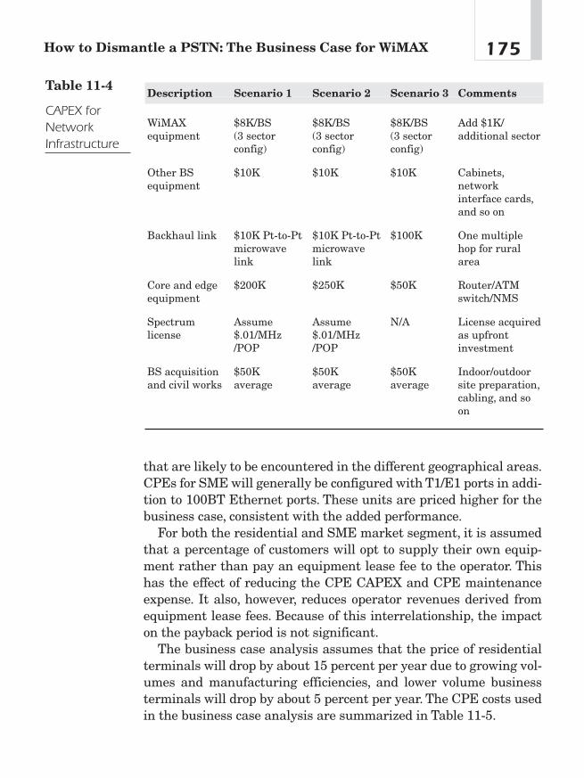
that are likely to be encountered in the different geographical areas.CPEs for SME will generally be configured with T1/E1 ports in addi-tion to 100BT Ethernet ports. These units are priced higher for thebusiness case, consistent with the added performance.
For both the residential and SME market segment, it is assumedthat a percentage of customers will opt to supply their own equip-ment rather than pay an equipment lease fee to the operator. Thishas the effect of reducing the CPE CAPEX and CPE maintenanceexpense. It also, however, reduces operator revenues derived fromequipment lease fees. Because of this interrelationship, the impacton the payback period is not significant.
The business case analysis assumes that the price of residentialterminals will drop by about 15 percent per year due to growing vol-umes and manufacturing efficiencies, and lower volume businessterminals will drop by about 5 percent per year. The CPE costs usedin the business case analysis are summarized in Table 11-5.
175How to Dismantle a PSTN: The Business Case for WiMAX
Description Scenario 1 Scenario 2 Scenario 3 Comments
WiMAX $8K/BS $8K/BS $8K/BS Add $1K/equipment (3 sector (3 sector (3 sector additional sector
config) config) config)
Other BS $10K $10K $10K Cabinets,equipment network
interface cards,and so on
Backhaul link $10K Pt-to-Pt $10K Pt-to-Pt $100K One multiple microwave microwave hop for rural link link area
Core and edge $200K $250K $50K Router/ATMequipment switch/NMS
Spectrum Assume Assume N/A License acquired license $.01/MHz $.01/MHz as upfront
/POP /POP investment
BS acquisition $50K $50K $50K Indoor/outdoor and civil works average average average site preparation,
cabling, and so on
Table 11-4
CAPEX forNetworkInfrastructure
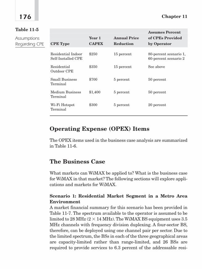
Operating Expense (OPEX) Items
The OPEX items used in the business case analysis are summarizedin Table 11-6.
The Business Case
What markets can WiMAX be applied to? What is the business casefor WiMAX in that market? The following sections will explore appli-cations and markets for WiMAX.
Scenario 1: Residential Market Segment in a Metro AreaEnvironmentA market financial summary for this scenario has been provided inTable 11-7. The spectrum available to the operator is assumed to belimited to 28 MHz (2 � 14 MHz).The WiMAX BS equipment uses 3.5MHz channels with frequency division duplexing. A four-sector BS,therefore, can be deployed using one channel pair per sector. Due tothe limited spectrum, the BSs in each of the three geographical areasare capacity-limited rather than range-limited, and 26 BSs arerequired to provide services to 6.3 percent of the addressable resi-
Chapter 11176
Assumes Percent
Year 1 Annual Price of CPEs Provided
CPE Type CAPEX Reduction by Operator
Residential Indoor $250 15 percent 80-percent scenario 1,Self-Installed CPE 60-percent scenario 2
Residential $350 15 percent See aboveOutdoor CPE
Small Business $700 5 percent 50 percentTerminal
Medium Business $1,400 5 percent 50 percentTerminal
Wi-Fi Hotspot $300 5 percent 20 percentTerminal
Table 11-5
AssumptionsRegarding CPE
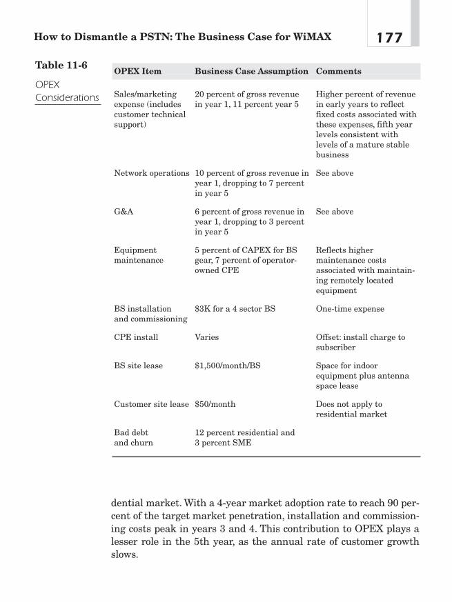
dential market. With a 4-year market adoption rate to reach 90 per-cent of the target market penetration, installation and commission-ing costs peak in years 3 and 4. This contribution to OPEX plays alesser role in the 5th year, as the annual rate of customer growthslows.
177How to Dismantle a PSTN: The Business Case for WiMAX
OPEX Item Business Case Assumption Comments
Sales/marketing 20 percent of gross revenue Higher percent of revenue expense (includes in year 1, 11 percent year 5 in early years to reflect customer technical fixed costs associated with support) these expenses, fifth year
levels consistent with levels of a mature stable business
Network operations 10 percent of gross revenue in See aboveyear 1, dropping to 7 percent in year 5
G&A 6 percent of gross revenue in See aboveyear 1, dropping to 3 percent in year 5
Equipment 5 percent of CAPEX for BS Reflects higher maintenance gear, 7 percent of operator- maintenance costs
owned CPE associated with maintain-ing remotely located equipment
BS installation $3K for a 4 sector BS One-time expenseand commissioning
CPE install Varies Offset: install charge to subscriber
BS site lease $1,500/month/BS Space for indoor equipment plus antenna space lease
Customer site lease $50/month Does not apply to residential market
Bad debt 12 percent residential and and churn 3 percent SME
Table 11-6
OPEXConsiderations

The CAPEX is dominated by WiMAX CPEs because it is assumedthat the operator would provide 80 percent of the equipment for thisscenario. This, of course, is offset by the $10 per month equipmentrental fees. As CPE prices decline, we would expect a higher per-centage of CPEs to be purchased by the customer to avoid the rentalexpense. With an internal rate of return (IRR) of 90 percent, this isclearly an attractive business model.
Chapter 11178
Spectrum Deployment Data
Frequency band 3.5 GHz WiMAX BS deployed 26
Channel BW in MHz 3.50 GHz Aggregate payload 1,005in Mbps/sq km
Spectrum required 28 Coverage area sq km 125in MHz
Addressable market Average data density 8
Mbps/sq kmHouseholds covered 388, 254 Population in 1,009,481
coverage area
Businesses covered N/A Assumed CPE Mix
Market penetration Percent of indoor 80 percent(5th year) residential CPE
Market adoption curve 4 years Percent of residential 80 percentCPEs operator-supplied
Residential market 6.3 percent Percent SME CPEs N/Aoperator-supplied
Residential voice 23 percent ARPU price erosion 5 percentservices
SME market N/A Average number 948subs/BS
SME voice N/A CAPEX/subscriber 5,328
Wi-Fi hotspot backhaul N/A Total CAPEX in $M $8.1
Net present value $3.6 IRR 90 percent(5 years) millions
Table 11-7
MarketSummary forScenario 1

Future Markets
Applications for WiMAX are limited only by the imagination of theentrepreneur. The following sections explore some relatively simpleapplications.
Replacing Cell Phone Infrastructure Figure 11-5 details howa cell phone network can be bypassed utilizing WiMAX infrastruc-ture. Table 11-8 lists cost savings of WiMAX versus cell phone infra-structure. According to Christensen’s Innovator’s Dilemma,disruptive technology is defined as being “cheaper, simpler, smallerand more convenient to use.” Note the cost differences among theplatforms contained in the infrastructure of the two network types.
Bypass by Substituting for the PSTN Assuming the processshown in Figure 11-5 became the standard practice for bypassing thecell phone network, what would be the demand for a “land line” tele-phone? The convenience of a mobile telephone offered at a cost com-petitive to that of the legacy land line could drive the copperwire-connected, circuit-switched telephone into extinction. Table11-9 compares infrastructure costs. Given the lower barrier to entrypresented by WiMAX, it is not hard to imagine a number of entre-preneurial companies seeking to take away market share fromincumbent telephone companies.
179How to Dismantle a PSTN: The Business Case for WiMAX
Legacy PSTN
PSTN Bypass with WiMAX and VolP
TransportAccess AccessSwitching Switching
WiMAX phone(coming 2007) WiMAX phone
(coming 2007)WiMAX BS(Access)
WiMAX BS(Access)
Softswitch(Switching)
IP(Transport)
Figure 11-5WiMAX as cellphone bypass
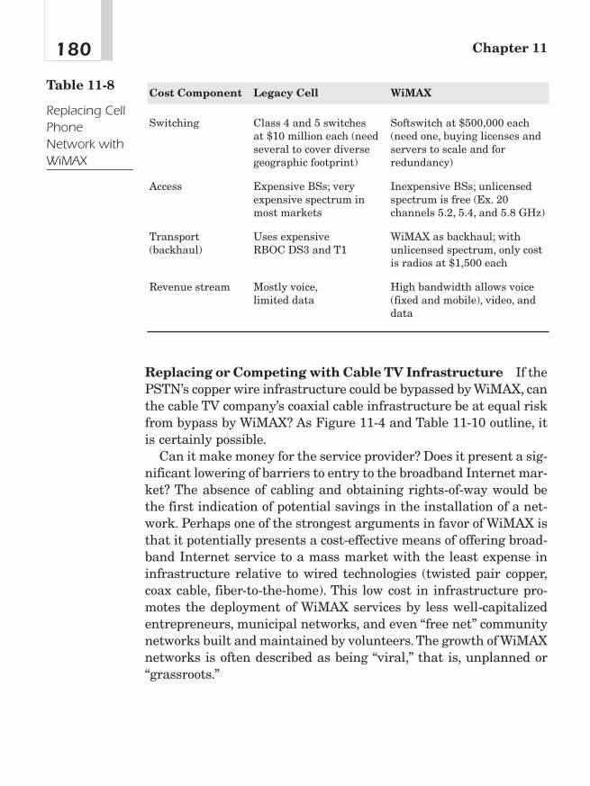
Replacing or Competing with Cable TV Infrastructure If thePSTN’s copper wire infrastructure could be bypassed by WiMAX, canthe cable TV company’s coaxial cable infrastructure be at equal riskfrom bypass by WiMAX? As Figure 11-4 and Table 11-10 outline, itis certainly possible.
Can it make money for the service provider? Does it present a sig-nificant lowering of barriers to entry to the broadband Internet mar-ket? The absence of cabling and obtaining rights-of-way would bethe first indication of potential savings in the installation of a net-work. Perhaps one of the strongest arguments in favor of WiMAX isthat it potentially presents a cost-effective means of offering broad-band Internet service to a mass market with the least expense ininfrastructure relative to wired technologies (twisted pair copper,coax cable, fiber-to-the-home). This low cost in infrastructure pro-motes the deployment of WiMAX services by less well-capitalizedentrepreneurs, municipal networks, and even “free net” communitynetworks built and maintained by volunteers. The growth of WiMAXnetworks is often described as being “viral,” that is, unplanned or“grassroots.”
Chapter 11180
Cost Component Legacy Cell WiMAX
Switching Class 4 and 5 switches Softswitch at $500,000 each at $10 million each (need (need one, buying licenses and several to cover diverse servers to scale and for geographic footprint) redundancy)
Access Expensive BSs; very Inexpensive BSs; unlicensed expensive spectrum in spectrum is free (Ex. 20 most markets channels 5.2, 5.4, and 5.8 GHz)
Transport Uses expensive WiMAX as backhaul; with (backhaul) RBOC DS3 and T1 unlicensed spectrum, only cost
is radios at $1,500 each
Revenue stream Mostly voice, High bandwidth allows voice limited data (fixed and mobile), video, and
data
Table 11-8
Replacing CellPhoneNetwork withWiMAX

181How to Dismantle a PSTN: The Business Case for WiMAX
Cost Component Legacy PSTN WiMAX
Switching Class 4 and 5 switches at Softswitch at $500,000 each $10 million each (need (need one, buying licenses several to cover diverse and servers to scale and for geographic footprint) redundancy)
Access Uses copper wire requiring Inexpensive BSs; unlicensedexpensive right-of-way for spectrum is free; except for wiring, poles, repeaters, roof and tower rights, little pedestals, and so on need for right-of-way
Transport (backhaul) Uses expensive RBOC DS3 WiMAX as backhaul; with and T1; fiber optic cable unlicensed spectrum, only requires trenching and cost is radios at $1,500 eachright-of-way
Revenue stream Voice, low bandwidth data High bandwidth allows voice (fixed and mobile),video, and data
Table 11-9
CostComparison:PSTN vs.WiMAX
Cost Component Legacy Cable TV WiMAX
Switching Video: Expensive headends Video: Cable TV Voice: Class 4 and 5 switches programming available via at $10 million each (need Voice IPTV: Softswitch at several to cover diverse $500,000 each (need one,geographic footprint); buying licenses and servers some players using to scale and for redundancy)VoIP (softswitch)
Access Expensive coax and cable; Inexpensive BSs; unlicensed expensive right-of-way spectrum is free
Transport Uses expensive satellite WiMAX as backhaul; with (backhaul) (hundreds of millions of unlicensed spectrum, only
dollars to build and launch) cost is radios at $1,500 eachor fiber
Table 11-10
CostComparison:Cable TV vs.WiMAX

Economics of Wireless in theEnterpriseThe economics of WiMAX in enterprise applications should beassessed in two ways: first, comparing applications where the wire-less network is simply less expensive to deploy than the wired net-work where both applications perform the same function and,second, analyzing situations where a wireless network enablesemployees to be more efficient. Money saved is money earned.
You Can “Take It with You When You Go”
WiMAX as a technology could gain wide acceptance in enterprisenetworks. The reasons for this are many including cost savings,mobility, and employee productivity. The origin of wireless networkslies in the convenience of not having to run Category 5 or telephonewiring in an enterprise environment. The cost of the wire itself is notso great; however, the labor to perform the installation and the bor-ing of holes in walls and other defacing of property necessary to runthe wire runs up the cost of a wired LAN as compared to subscribingto a wireless broadband service.
A timeless wisdom regarding death and personal wealth goes “Youcan’t take it with you when you go.” Most commercial lease agree-ments in North America hold a proviso that wired infrastructuremust remain in the building when the enterprise tenant vacates thepremises (most do so for more advantageous rent). This is a sunkcost that the enterprise tenants lose when they move to anotherbuilding space. In contrast, the WiMAX broadband Internet serviceis almost completely portable. The deployment of a wireless enter-prise network allows the enterprise greater flexibility when shop-ping for more advantageous rents. Table 11-11 offers a brief outlineof savings for wireless versus wired office space.
The WiMAX/Wi-Fi Wireless Office Significant savings can beachieved by moving the office from “wired” to “wireless.” Figure11-6 illustrates how an office could receive its data from a WiMAX
Chapter 11182
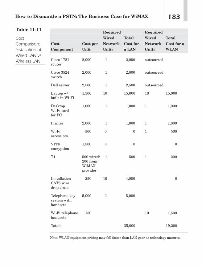
183How to Dismantle a PSTN: The Business Case for WiMAX
Required Required
Wired Total Wired Total
Cost Cost per Network Cost for Network Cost for a
Component Unit Units a LAN Units WLAN
Cisco 1721 2,000 1 2,000 outsourcedrouter
Cisco 3524 2,000 1 2,000 outsourcedswitch
Dell server 2,500 1 2,500 outsourced
Laptop w/ 1,500 10 15,000 10 15,000built-in Wi-Fi
Desktop 1,000 1 1,000 1 1,000Wi-Fi card for PC
Printer 2,000 1 1,000 1 1,000
Wi-Fi 500 0 0 1 500access pts
VPN/ 1,500 0 0 0encryption
T1 500 wired/ 1 500 1 200200 from WiMAX provider
Installation 250 10 4,000 0CAT5 wire drops/runs
Telephone key 5,000 1 5,000system with handsets
Wi-Fi telephone 150 10 1,500handsets
Totals 35,000 19,200
Note: WLAN equipment pricing may fall faster than LAN gear as technology matures.
Table 11-11
CostComparison:Installation ofWired LAN vs.Wireless LAN

source. Office components such as computers, telephones, and print-ers can all be networked via wireless means. Refer to Table 11-11 fora comparison of cost components of both the wired and wirelessoffice.
Economics of WiMAX in Public Networks
What is the economic pull to grow wireless public networks? The pre-vious section of this chapter described the advantages of WiMAX inprivate networks. How then will public networks become accepted in
Chapter 11184
WiMAX CPE
Wi-Fi Access Pointand Router Wi-Fi Phone
IP Phone
Wi-Fi Laptop
Wi-Fi Desktop
Wi-Fi Printer
Figure 11-6The wirelessoffice: NoteWiMAX asbroadbandexternal feed toWi-Fi internalnetwork
our economy? In an ideal world, some form of ubiquitous wirelesscoverage would extend to at least every residence and small businessin a metropolitan area. From that goal, extending the coverage tosmall towns and farms could occur at a rapid pace, assuming a busi-ness model propels that growth.
Although the Telecommunications Act of 1996 was intended tobring competition to the local loop, some six years after its passage,fewer than 10 percent of United States residences enjoy any choicein their local telephone service provider. Competition will never comein the local loop but rather to the local loop. The act prescribed a for-mula for competitors to lease facilities (copper wire and switchspace) from incumbent service providers. One of the reasons compe-tition in the local loop is lacking is simply the cost of deploying com-peting strands of copper wire.
According to FCC studies, the cost to install copper loop plantdepends on the density of households in the service area. This costcan range from $500 per household in the least expensive urbansites to a typical $1,000 in dense suburban areas, ascending to$10,000/loop in outlying rural areas. Economies of scale apply here.A competitor cannot come close to matching incumbent costs on loopplant because a competitor with a low market share has, effectively,rural density (and costs), even in an urban area.1 Competitors to anincumbent telephone company must, then, consider their return oninvestment (ROI) on a per customer basis. If the competitor will real-ize $40 per month on a customer, for example, the ROI period couldbe very long. If a wireless service provider could persuade the cus-tomer to purchase his or her own customer premises equipment(CPE), the wireless competitor could potentially be more competitivethan any other form of competitive service compared to the incum-bent telephone company.
Advantages to SOHO or Residence Earlier scenarios detailingcost savings for WiMAX service providers carry through to residen-tial subscribers as well. Table 11-12 outlines savings for residentialsubscribers who have their services (converged) from one wireless
185How to Dismantle a PSTN: The Business Case for WiMAX
1Fred Goldstein (telecommunications consultant), interview, November 28, 2002.
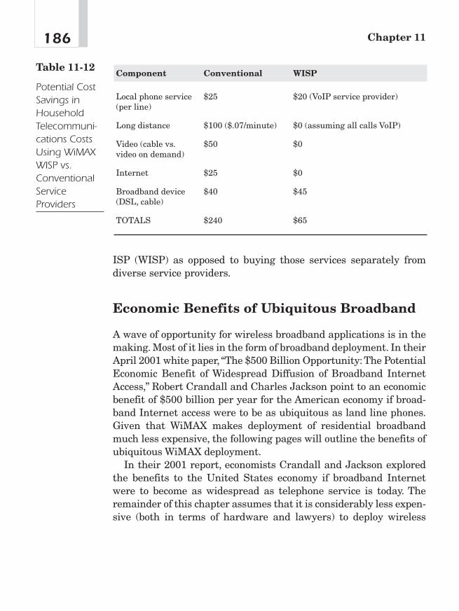
ISP (WISP) as opposed to buying those services separately fromdiverse service providers.
Economic Benefits of Ubiquitous Broadband
A wave of opportunity for wireless broadband applications is in themaking. Most of it lies in the form of broadband deployment. In theirApril 2001 white paper, “The $500 Billion Opportunity:The PotentialEconomic Benefit of Widespread Diffusion of Broadband InternetAccess,” Robert Crandall and Charles Jackson point to an economicbenefit of $500 billion per year for the American economy if broad-band Internet access were to be as ubiquitous as land line phones.Given that WiMAX makes deployment of residential broadbandmuch less expensive, the following pages will outline the benefits ofubiquitous WiMAX deployment.
In their 2001 report, economists Crandall and Jackson exploredthe benefits to the United States economy if broadband Internetwere to become as widespread as telephone service is today. Theremainder of this chapter assumes that it is considerably less expen-sive (both in terms of hardware and lawyers) to deploy wireless
Chapter 11186
Component Conventional WISP
Local phone service $25 $20 (VoIP service provider)(per line)
Long distance $100 ($.07/minute) $0 (assuming all calls VoIP)
Video (cable vs. $50 $0video on demand)
Internet $25 $0
Broadband device $40 $45(DSL, cable)
TOTALS $240 $65
Table 11-12
Potential CostSavings inHouseholdTelecommuni-cations CostsUsing WiMAXWISP vs.ConventionalServiceProviders
broadband Internet to a residence than a similar service thatdepends on wiring (copper wire from the phone company or coaxcable from the cable TV company). Both telephone wires and cableTV coax cable run by (are accessible by) almost 90 percent of Amer-ican homes. The physical cost of connecting a home to the Internet inmost residential applications is not that high. However, for a newmarket entrant, gaining the right-of-way from private land ownersand public utilities to get to those households will not be possible inmost cases without costly legal procedures. Revenue generated fromsubscription fees may not offset the legal costs of running wire orcable to that residence.
Using WiMAX as a means of access does not require legal dealingsfor rights-of-way and, relative to wired infrastructure, can bedeployed much more quickly. As evidenced by the efforts of CLECs tooffer competitive residential telephone service using incumbent tele-phone poles and other incumbent-owned and incumbent-operatedfacilities, it is far easier to bypass PSTN facilities than to utilizethem via legal means. A wireless service provider need only install aBS and turn up service. The remainder of this chapter will explorethe benefits of ubiquitous residential broadband Internet access,assuming the ease and economy of WiMAX is a catalyst for achiev-ing the same levels of penetration for broadband Internet access asresidential telephone service has today.
As the uses of broadband multiply, the value to subscribers risesfar above the monthly subscription price. This is the consumer sur-plus from the innovation. Producers of new services that rely onbroadband (see example of i-mode-type services, Net2Phone, and soon), of products used in conjunction with broadband service(softswitches, media gateways, IP phones, residential gateways),and even of the broadband service itself also gain from the greaterdiffusion of broadband. The producer surplus that is generated bysales is a real benefit to producers and, therefore, to the economy. Atpresent, no more than 8 percent of American households subscribe toa broadband service; only slightly more than 50 percent subscribe toan Internet service of any kind; and 94 percent subscribe to ordinary
187How to Dismantle a PSTN: The Business Case for WiMAX

telephone service.2 Were broadband to become ubiquitous, it wouldresemble current telephone service in its household penetration.
Producer Benefits Figure 11-7 demonstrates the economic pull-through of wireless broadband.
One of the reasons many IP backbone and wireless local loop car-riers went bankrupt is that they could not deliver bandwidth to abroad market. The “bottleneck” to the last mile remains the accesscontrolled largely by telephone companies with their ubiquitoustwisted-pair copper wire. Cable TV companies now service a major-ity of American homes. WiMAX presents a means of reaching cus-tomers anywhere and everywhere with minimum cost to the serviceprovider.
WiMAX will create a cycle of adoption that will drive technologypurchases and upgrades by enterprises, retailers, service providers,
Chapter 11188
• Road• Multiple family users• Previously unconnected users
• Portable enterprise apps• Pervasive access to enterprise VPN• Gaming• Multimedia• OS• New types of terminal devices• Wi-Fi standard network edge devices
• Semiconductors• Security• Radio infrastructure• Broadband infrastructure• Software support
• DSL/Cable rollout• Public hotspots• Community wireless• Home networking• Enterprise parameters
$$$
TechnologyImprovements
LowerCost
GreaterPervasiveness
MoreApplications &
Equipment
MoreUsers
Already below $300
Figure 11-7Economic pull-through ofwirelessbroadband(Figure courtesyGoldman Sachs)
2The number of broadband subscribers (DSL plus cable modems) was 7.3 million asof March 2001. See “Failure of Free ISPs Triggers First-Ever Dip, to 68.4 MillionOnline Users: Cable Modem Boom Continues, as DSL Sign-ups Lag,” Telecommuni-cations Reports,April 2001.The estimates for Internet and telephone service are fromauthors’ tabulations using the Current Population Survey for August 2000.
government, and individuals for the following three reasons. First, itoffers a means of delivery that is “cheaper, simpler, smaller, and moreconvenient” than wired (telephone and cable TV) means of delivery.WiMAX service requires either the presence or installation of a BSand customer premise equipment. The larger the environment (thenumber of coverage areas, number of users supported, and so on), themore infrastructure equipment and network bandwidth arerequired, thus spurring sales of BSs, customer premise equipment,and so on.
Once WiMAX is available in a given area, it will spur the purchaseof more mobile computers, PDAs, pocket PCs, and other wirelessdevices. This is particularly relevant in the home, where WiMAXenables broadband connections to be shared easily among multiplePCs and, ultimately, other devices as well. Major PC vendors willsoon include WiMAX support. Chipmakers and laptop computermanufacturers will soon offer WiMAX capabilities in their products.These market drivers include home networking, home multimedia,smart appliances, and VoIP. These applications require new plat-forms such as home access points and voiceover WiMAX telephonydevices.3
Computer Sales The expansion of the demand for broadband willcreate additional demand for computers and networked home appli-ances. Approximately 40 percent of all United States households donot currently have a computer.4 These households are clearly notequipped to connect to the Internet at any speed. Of the 60 percentof households with computers, many will need to upgrade theirequipment to obtain greater processing speed, more random-accessmemory, or greater hard-drive capacity. Still others will choose tobuy more advanced equipment such as storage devices, MP3 play-ers for music downloads, and LCD projectors for viewing video down-loaded via a high-speed Wi-Fi or WiMAX connection. Applications
189How to Dismantle a PSTN: The Business Case for WiMAX
3 Chris Fine, “Watch Out for Wi-Fi,” white paper from Goldman Sachs.4 The most recent estimate from the Bureau of the Census for June 2000 was 41.5 per-cent. More recent estimates from TNS suggest that about 50 percent of householdsnow have access to the Internet. See TNS Telecoms, ReQuest Market Monitor NationalConsumer Survey, vol. 3 (2001).
(video, telephony) that the following pages will explore could verywell drive much of the remaining 40 percent of households withoutcomputers to make the leap and install a computer in their homes.
Crandall and Jackson estimate broadband’s stimulus on house-hold purchases of broadband-related equipment would be thatUnited States household spending on computer equipment, periph-erals, and software would resume its 1991—1995 rate of growth of14.3 percent per year, rather than continuing at its 1995—1999growth rate of 10.4 percent per year. If growth returns to its 1991—1995 pace, by 2006 total spending would be $80 billion, rather than$66 billion—an increase of $14 billion. By 2011, the difference wouldbe $53 billion per year. Were the broadband revolution to acceleratehousehold equipment expenditures by another 3 percent per year to17.3 percent annual growth, the additional spending in ten yearswould be $110 billion per year.5
Consumer Benefits The most straightforward estimate of thevalue of enhanced availability of broadband derives from informa-tion on consumer subscriptions to broadband services.
An Estimate Based on Current Demand Price elasticity ofdemand is a relationship of change in demand to the change in price.Given current broadband penetration of 8 percent and an averageprice of the service of $40 per month, total broadband revenues maybe estimated at $480 times 8.4 million or $4 billion per year. Assum-ing that the demand for such service is linear with an elasticity of�1.0, the value of the service to these consumers—the consumersurplus—is $2 billion per year in addition to the $4 billion they pay.If the demand elasticity is �1.5, the consumer surplus falls to $1.4billion.
Were broadband to spread to 50 percent of households at $40 permonth through a shift of a linear demand curve with constant slope,the annual expenditure on the service would rise to $31.2 billion. At50 percent penetration, the additional value to consumers would rise
Chapter 11190
5Robert Crandall and Charles Jackson,“The $500 Billion,” white paper from CriterionEconomics LLC.
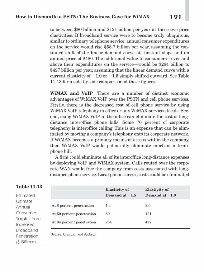
to between $80 billion and $121 billion per year at these two priceelasticities. If broadband service were to become truly ubiquitous,similar to ordinary telephone service, annual consumer expenditureson the service would rise $58.7 billion per year, assuming the con-tinued shift of the linear demand curve at constant slope and anannual price of $480. The additional value to consumers—over andabove their expenditures on the service—would be $284 billion to$427 billion per year, assuming that the linear demand curve with acurrent elasticity of �1.0 or �1.5 simply shifted outward. See Table11-13 for a side-by-side comparison of these figures.
WiMAX and VoIP There are a number of distinct economicadvantages of WiMAX VoIP over the PSTN and cell phone services.Firstly, there is the decreased cost of cell phone service by usingWiMAX VoIP telephony in office or any WiMAX-serviced locale. Sec-ond, using WiMAX VoIP in the office can eliminate the cost of long-distance interoffice phone bills. Some 70 percent of corporatetelephony is interoffice calling. This is an expense that can be elim-inated by moving a company’s telephony onto its corporate network.If WiMAX becomes a primary means of access within the company,then WiMAX VoIP would potentially eliminate much of a firm’sphone bill.
A firm could eliminate all of its interoffice long-distance expensesby deploying VoIP and WiMAX system. Calls routed over the corpo-rate WAN would free the company from costs associated with long-distance phone service. Local phone service costs could be eliminated
191How to Dismantle a PSTN: The Business Case for WiMAX
Elasticity of Elasticity of
Demand at �1.5 Demand at �1.0
At 8 percent penetration 1.4 2.0
At 50 percent penetration 80 121
At 94 percent penetration 284 427
Source: Crandall and Jackson
Table 11-13
EstimatedUltimateAnnualConsumerSurplus fromIncreasedBroadbandPenetration ($ Billions)
as well. If firms employed dual frequency telephone handsets, allinteroffice calls could be made on the corporate WAN. Local callscould also be routed to other WiMAX or IP enabled handsets withoutcontact with the PSTN. Other handsets could be reached using thecell phone network.
Soon the demand for broadband will reflect not only the growingpotential uses of the Internet but also the prospect for using thesebroadband connections to obtain voice telephone services currentlyprovided over a narrowband connection.The use of broadband accessto carry voice—ordinary telephone calls—as well as data will deliverto consumers substantial savings that are not captured in currentdemand estimates. Voice communications can be compressed, put inpackets, and sent over an IP connection.
The cost savings from integrated access will be significant. Reli-able Internet telephony would eliminate the need for second or thirdlines in households for teenagers or fax machines. The FCC esti-mated that the average household spent $55 per month on local andlong-distance telephone service in 1999, and there were 0.289 addi-tional lines for each household with telephone service.6
Within a few years, broadband access will permit consumers tosubstitute other services for services that now cost $55 per month.The FCC estimates that the average residence spends $34 permonth for local telephone service and $21 for long-distance tele-phone service. Part of that local telephone service cost is for the loopthat is used for the broadband service. Consumers continue to incurmost of those loop costs when broadband service is used, but theyavoid the cost of the analog line card, the voice switch, and the voicetransmission lines. Vo802.16 should lower the costs of both local andlong-distance telephone service, while providing residences with theequivalent of several telephone lines. Crandall and Jackson estimate
Chapter 11192
6FCC,“Trends in Telephone Service,”2nd Report (2000),www.fcc.gov/Bureaus/Common_Carrier/Reports/FCC-State_Link/IAD/trend200.pdf.7The FCC’s numbers indicate that the average household with telephone service has1.289 access lines and pays local service fees of $34 per month.Assuming that all linescost the same (which is not quite right but is reasonable), the average household withtelephone service in 1999 paid $7.62 per month for additional line service. If thosehouseholds without a second line today place an average value of no more than $3.40per month for second line of service, then the average household will value a secondline at $10 per month or more.

that such savings could average $25 per month per household. Inaddition, households with broadband service would get the equiva-lent of multiple voice telephone lines. They estimate that this addi-tional service or option of service could be worth $10 per month tothe average household.7 Thus, in the longer run (say a decade fromnow), broadband access could deliver voice communications benefitsof about $35 per month (or $420 per year) to the average householdwith telephone service. If we assume that 122.2 million householdshave telephone service, these benefits would total $51.4 billion peryear, assuming no growth in voice usage. The actual value could bemuch higher.
The substantial economic benefits (principally savings fromexpenditures on telephone service) created by providing multipleservices over a high-speed line almost cover the cost of a high-speedline—we have estimated that benefits of $35 per month are createdby a broadband connection that costs $40 per month. These savingsare one reason why we believe that it is reasonable to expect that the
193How to Dismantle a PSTN: The Business Case for WiMAX
Source Low Estimate High Estimate
Direct Estimate
Broadband Access Subscription 284 427
Household Computer/ 13 33Network Equipment
Total Benefits 297 460
Alternative Estimates; Benefits Deriving from
Shopping 74 257
Entertainment 77 142
Commuting 30 30
Telephone Services 51 51
Telemedicine 40 40
Total Benefits 272 520
Table 11-14
Summary ofConsumerBenefits fromUniversalBroadbandDeployment ($ Billions per Year)
fraction of households with high-speed access services will ulti-mately approach the fraction that has telephone service today. Referto Table 11-14 for a list of the benefits of universal broadband deploy-ment.
Speeding Up the Adoption of Broadband Access ProvidesBenefits Earlier The present value of the difference between thebase adoption scenario and the much faster adoption scenario of ourprevious example is 140 percent of one year’s worth of the benefitsof ubiquitous broadband adoption by households.8 Thus, if oneassumed that broadband, when fully adopted, generated benefits of$300 billion per year to American consumers, a policy change thatmoved our society from the baseline adoption curve to the muchfaster curve would generate benefits with a net present value ofabout $420 billion.9 The increase in the present value of producers’surplus would be about $80 billion. This acceleration is thereforeworth $500 billion to U.S. consumers and producers.
How could speeding up the adoption of a technology have suchmassive benefits? The key lies in the substantial benefits that ubiq-uitous broadband can convey to consumers. Once virtually every-one has the service, the network effects from developing newservices become very large. Moving these benefits forward a fewyears can create very large benefits—even when evaluated fromtoday’s perspective. The powerful advantage of WiMAX over thecurrent, dominant broadband technologies, DSL and cable modem,is that in the words of Clayton Christensen, it is “cheaper, simpler,smaller, and more convenient to use (deploy).” The lack of a require-ment for wires and their incumbent, expensive rights-of-way hasthe potential to give the wireless service provider a significantadvantage over the wired incumbent.
Chapter 11194
8This was calculated using a discount rate of 10 percent and assuming a 2 percentper year growth in the economy.9These present values are 2.8 and 4.2 times the ultimate value of broadband adop-tion when evaluated at an interest rate of 10 percent per year.

ConclusionIn a summer 2003 televised interview of Intel founder Andy Grove,interviewer Charlie Rose asked his guest, “What’s the next bigthing?” Mr. Grove, thinking he was being hit up for the equivalent ofa stock tip, fended off his interviewer until Mr. Rose parried with adeeper inquiry mentioning Intel’s Centrino chip and other wirelessinitiatives at Intel. Mr. Grove then jumped in with both feet. “Wire-less is the next big thing,” he summarized, “It will be bigger thantelegraphy or even telephony itself.”
At the time of that interview, WiMAX was still an obscure tech-nology, but as Intel is the lead chipmaker offering WiMAX technol-ogy, Mr. Grove was no doubt well aware of the potential impact ofWiMAX on the telecommunications market and the world as awhole. As pointed out in this chapter, no existing subindustry intelecommunications (cable TV, wire line telephony, cell phones, Inter-net access) will go untouched.
195How to Dismantle a PSTN: The Business Case for WiMAX

This page intentionally left blank
Projections:WiMAX Is aDisruptiveTechnology
CHAPTER 1212
Copyright © 2005 by The McGraw-Hill Companies, Inc. Click here for terms of use.
This is a very exciting time in the telecommunications industry.There is a powerful clamor for service providers to roll out the tripleplay of voice, video, and data. A quadruple play may include mobilephone and data services. Given the commonality of IP, all thatremains is an inexpensive means of delivering those IP bits to thesubscriber, thus banishing the curse of the “last mile bottleneck.”WiMAX breaks open that last mile bottleneck.
Disruptive TechnologyIn his Harvard University business book, The Innovator’s Dilemma,Clayton Christensen describes how disruptive technologies have pre-cipitated the failure of leading products and their associated andwell-managed firms. Christensen defines criteria to identify disrup-tive technologies, regardless of their market. These technologieshave the potential to replace mainstream technologies and theirassociated products and principal vendors. Christensen abstractlydefines disruptive technologies as “typically cheaper, simpler,smaller, and, frequently, more convenient” than their mainstreamcounterparts.1
Wireless technologies, relative to incumbent wired networks, are adisruptive technology. For the competitive service provider, WiMAXis “cheaper, simpler, smaller, and, frequently, more convenient” thancopper wire or coax cable and their associated infrastructures. Inorder for a technology to be truly disruptive, it must disrupt anincumbent vendor or service provider. Some entity must go out ofbusiness before a technology can be considered disruptive. Althoughit is too early to point out incumbent service providers driven out ofbusiness by WiMAX, its technologies are potentially disruptive toincumbent telephone companies. The migration of wire line tele-phone traffic from ILEC to cellular is a powerful example of thistrend. The migration to voice over WiMAX will certainly mark thedisruption of telephone companies as we know them.
Chapter 12198
1Clayton Christensen, The Innovator’s Dilemma (Boston: Harvard Business SchoolPress, 1997), p. 264.

How WiMAX Will Disrupt theTelephone IndustryIf disruptive technology is defined as being “cheaper, simpler,smaller, and more convenient to use,” how, then, is WiMAX cheaper,simpler, smaller, and more convenient to use than legacy telecom-munications infrastructure?
Cheaper
A WiMAX network is much cheaper to deploy than a comparableTDM-switched, copper wire-based legacy PSTN infrastructure. TheTelecommunications Act of 1996 failed to produce any real competi-tion in the local loop, as it was economically impossible to build anddeploy a network that could compete with an entrenched and finan-cially protected monopoly.
WiMAX changes all that. As explored earlier, a competitive net-work can be built for a fraction of the cost of a legacy network. Fur-thermore, it can be operated for a fraction of the operations,administration, maintenance, and provisioning (OAM&P) of thePSTN. Potentially, it offers more services than the PSTN, generatingmore revenue than a PSTN voice-centric infrastructure.
By virtue of being cheaper to purchase and operate, a WiMAX net-work marks a significant lowering of barriers to market entry. Nolonger is a voice service the exclusive domain of a century-old pro-tected monopoly. This lowering of the barrier to entry will allow mul-tiple types of service providers to offer voice services in directcompetition with the legacy telephone monopoly. This list of serviceproviders could include WISPs, ISPs, power companies, municipali-ties, cable TV companies, and new market entrants. For the price ofa new pick-up truck, a rural ISP can be the telephone company, cableTV company, and potentially the cell phone company for a given com-munity. This is very disruptive.
199Projections: WiMAX Is a Disruptive Technology
Simpler
Given its 100-year evolution, the PSTN is painfully complex. Serviceproviders have melded one technology on top of another over the lastcentury. COs are, in many cases, museums of switching history, asoperators rarely discard switching equipment that still functions(and enjoys a very generous depreciation schedule).
WiMAX service providers will not be burdened by the past.Rather, a WiMAX is IP-based, meaning it is far more efficient inoperation. The key here is open standards as opposed to the closedsystems of the legacy PSTN. The open standards allow a serviceprovider to mix and match components of the network. Much of asoftswitched voice network is software-dependent, which can beupgraded easily and frequently.The use of IP-based media (voice andvideo) further simplifies service delivery.
Smaller
One recurring excuse for the monopoly of telephone or cable TV com-panies is that they were/are an “economy of scale,” in that somethingso large, so complex, and so costly could succeed only if it were pro-tected as a monopoly. A WiMAX network can be easily deployed as amodular system by even the smallest service providers in rural ordeveloping economies. The same is true of corporate campuses ormultidwelling units (MDUs). Given that VoIP, IPTV, or Internetoperations are geographically independent of the subscriber, a ser-vice provider can provide switching for widely dispersed subscribers.
The footprint of a WiMAX CPE is comparable to that of a laptopcomputer. The antenna and radio are also about the size of a laptop.This makes deployment fast and inexpensive. The smaller sizemakes deployment and management that much easier.
More Convenient to Use
The PSTN may be doomed by voice, the commodity for which it wascreated. Ditto for cable TV networks and their video equivalent.Business and residential markets now demand a convenient access
Chapter 12200
to broadband data services. The PSTN does not offer this functionefficiently. WiMAX networks offer easily deployed and operatedbroadband data services with the triple play of voice, video, and data.WiMAX works because the flexibility of its all-IP infrastructureoffers the subscriber greater convenience (VoIP, IPTV, and IP datafrom one service provider).
DeconstructionIn their 1999 book titled Blown to Bits, Phillip Evans and ThomasWurster explore how certain industries have been “deconstructed” bythe Internet. That is, the emergence of information or services avail-able via the Internet has caused firms to lose sales and marketshare, if not their entire business, due to the emergence of new tech-nologies. Examples of those industries include travel agencies, retailbanks, and automobile retailers. The following pages will investigatethe potential deconstruction of the North American telecom industryby Internet-related telephony applications.2
The telecom sector in recent years has been deconstructed by tech-nologies that are Internet-related, if not by the Internet itself. Thedelivery of telephony features to a voice service via IP would also bean example of deconstruction of the telecom service provider indus-try by an Internet-related technology. IPTV does the same for thecable TV industry. Cell phone companies may find themselves simi-larly deconstructed, once mobility in WiMAX reaches the market.
Goetterdammerung or CreativeDestruction in theTelecommunications IndustryEvery month, North American local exchange carriers lose thou-sands of their TDM line accounts. Furthermore, some are deeply in
201Projections: WiMAX Is a Disruptive Technology
2Phillip Evans and Thomas Wurster, Blown to Bits (Boston: Harvard BusinessSchool Press, 1999).

debt. Percentage-wise, this marks the only time since the GreatDepression that telephone companies have actually decreased in linecount.
How could the telephone company lose business? The answer issimple: Competition is slowly coming to as opposed to in the localloop. Subscribers are taking their business elsewhere. Many com-peting technologies allow subscribers to divorce themselves from theformer monopolies. Many residential subscribers have given all theirvoice business to their cell phone service provider, and businesseshave taken their voice business to data companies that offer VoIPover a data connection (ICG, Vonage). Capital expenditures for tele-phone companies are at record lows. The near-monopolistic vendorsof the past are mired deeply in debt.
Is there no optimism in this market? If one is looking for a recov-ery in the telecommunications market as we know it, there is nocause for optimism. Austrian-born Harvard economist Josef Schum-peter, if he were alive today, would probably refer to the currenttelecommunications industry as being a good case of creativedestruction. That is, capitalism is cyclical: Almost all industries grow,mature, and die.
The telecommunications industry as we know it is no exception tothis rule of capitalism. Shielded as a quasi-monopoly for most of itslife, the North American local exchange carrier had no reason tocompete or to innovate. The service it provides, voice, is littlechanged over 100 years ago. The monopolistic protection came to anend with the Telecommunications Act of 1996. The resulting boom inthe industry buoyed those incumbent carriers as the “high tide thatraises all boats.” The telecommunications bust has seen the demiseof many competitors in the local loop but has yet to seriouslythreaten the survival of the incumbents. WiMAX may change that.Incumbent telcos that cannot adapt to the challenges posed byWiMAX, VoIP, and IPTV will die.
WiMAX potentially strikes at the very heart of the incumbenttelco business paradigm that relied on a high barrier to entry to thevoice market. Technology will inevitably march forward. WiMAXtechnology is “cheaper, simpler, smaller, and more convenient to use.”It is a disruptive technology that, after matching the incumbent
Chapter 12202

technology, has qualities of its own that will allow it to supersede theincumbent’s legacy infrastructure. WiMAX, unlike incumbentcircuit-switched infrastructures, is a technology that can be quicklyand cheaply deployed anywhere in the world. The North Americantelephony market (services) is estimated to do almost $1 trillion inbusiness annually. Service providers, regardless of the technologiesthey use, will, in a Darwinian struggle, seek to get an ever-increas-ing larger market share. That market share can come only at theexpense of the incumbents.
In summary, there will not be a recovery in the North Americantelecommunications market. There will be a rebirth. That rebirthwill come in the form of new service providers offering new serviceswith new technology. It is not certain when the exact date of the endof circuit-switched telephony and the century-old PSTN will come.The best analogy of this passing is in the Wagnerian opera “Goetter-daemmerung” or “twilight of the gods.” “Daemmerung,” in this case,translates into “twilight,” which in the German sense of the word canmean twilight at dusk and at dawn. In the case of the North Ameri-can telecommunications market, it is the dusk for the incumbentsand their legacy voice-centric networks, and it is dawn for WiMAX.
203Projections: WiMAX Is a Disruptive Technology

This page intentionally left blank
Considerationsin Building
Wireless Networks
APPENDIX AA
Copyright © 2005 by The McGraw-Hill Companies, Inc. Click here for terms of use.

This appendix is not intended as a “how to” guide but rather to givethe reader a broad overview of the foibles and tricks of the trade forthe installation of wireless networks.
Successful deployment of a WiMAX system requires design, plan-ning, implementation, operation, and maintenance.This chapter pro-vides a very brief overview of what the wireless network plannerneeds to consider when deploying a WiMAX network.
DesignSome of the questions that must be addressed in selecting a WiMAXsolution lead to trade-offs—such as speed versus range. Others havemutually exclusive answers—such as proprietary versus standards-based extensions. Some of the questions that need to be addressedinclude: What is the network topology? What kinds of links will beused? What is the environment like? What is the throughput, range,and bit error rate (BER) that is needed? Will one need tolerance formultipath? What frequency band will be used with what protocols?Can the solution be off-the-shelf or surplus standards based, or willit need to be custom?
Network Topology
One of the major factors that determine throughput, robustness, reli-ability, security, and cost is the geometric arrangement of the net-work components, or the topology. Five major topologies are in usetoday in wired networks: Bus, Star, Tree, Ring, and Mesh. In Wire-less LAN only, the Star and Mesh have analogues with the wirednetworks.
The mesh topology is a slightly different type of network architec-ture than the better-known star topology, except that there is no cen-tralized BS. Nodes that are in range of one another can communicatefreely, as shown in Figure A-1.
Appendix A206

Wireless mesh networks are an exciting new topology for creatinglow-cost, high-reliability wireless networks in a building, across acampus, or in a metropolitan area. In a mesh network, each wirelessnode serves as both an AP and wireless router, creating multiplepathways for the wireless signal. Mesh networks have no singlepoint of failure and thus are self-healing. A mesh network can bedesigned to route around line-of-sight obstacles that can interferewith other wireless network topologies. However, using a wirelessmesh currently requires the use of specialized client software thatwill provide the routing function and put the radio into ad-hoc orinfrastructure mode as required.
Link Type
WiMAX systems can be built using either point-to-point or point-to-multipoint links. FCC regulations allow both types of links, but theycome with implications for the power to the antenna. See Figure A-2.
Environment
What is the environment like? Is it indoors or outdoors? Is there aline of sight, or are there obstacles in the path? See Figure A-3.
207Considerations in Building Wireless Networks
To Wired NetworkAccess Point
Laptop computer
Laptop computer
Laptop computer
Workstation
Figure A-1A wireless meshnetwork
Throughput, Range, and Bit Error Rate(BER)
Throughput has trade-offs with range and BER. The best networkdesigns balance these factors by limiting the data rate according todata quantity and latency requirements. Fundamentally, in anyapplication there is a trade-off between three factors: range,throughput, and BER. Because the throughput is limited by the pro-tocol (802.11 WiMAX) and because BER has to be reasonably high toget throughput, the only variable left is the range. The availablerange at a given throughput can be calculated using a link budget.
Appendix A208
Point-to-Point Point-to-MultipointFigure A-2Point-to-pointand point-to-multipoint
Line of Sight (LOS): Optimal
IP cloud
Non Line of Sight (NLOS)
Not optimal: significant loss of signal
Figure A-3Line-of-sight vs.non-line-of-sightsignal

Multipath Fading Tolerance
Non-line-of-sight positioning must allow for significant multipathfading. Multipath is created by reflections canceling the main signal.The choice of frequency band and protocols will, in part, depend onhow much multipath can be tolerated.
Link Budget
A fundamental concept in any communications system is the linkbudget, or the summation of all the gains and losses in a communi-cations system. The result of the link budget is the transmit powerrequired to present a signal with a given signal-to-noise ratio (SNR)at the receiver to achieve a target BER.
For any wireless protocol, it is sufficient to consider factors such aspath loss, noise, receiver sensitivity, and gains and losses from anten-nas and cable. Before calculating a link budget, factors such as thefrequency band must be determined.
Frequency Band
Some wireless technologies can be deployed on four unlicensed fre-quency bands in two bands called ISM and Unlicensed NationalInformation Infrastructure (U-NII). The 2.4 GHz ISM band has an inherently stronger signal with a longer range and can travelthrough walls better than the 5 GHz U-NII bands can. However,the U-NII band allows more users to be on the same channel simul-taneously. The 2.4 GHz ISM band has a maximum of three non-over-lapping 22 MHz channels while the 5 GHz band has fournon-overlapping 20 MHz channels in each of the U-NII bands.
Industrial, Scientific, and Medical (ISM) Band The ISMbands were originally reserved internationally for noncommercialuse of RF electromagnetic fields for industrial, scientific, and med-ical purposes. More recently, they have also been used for license-freeerror-tolerant communications applications such as cordless phones,Bluetooth, and Wireless LAN.
209Considerations in Building Wireless Networks
U-NII Band Devises that will provide short-range, high-speed,wireless, digital communications can use the U-NII bands. Thesedevices, which do not require licensing, will support the creation ofwireless metro area networks (WMANs) and facilitate access to theInternet. The U-NII spectrum is located at 5.15 to 5.35 GHz and5.725 to 5.825 GHz.
The 5.15 to 5.25 GHz portion of the U-NII band is intended for useby indoor, short-range networking devices. The FCC adopted a 200-mW EIRP limit to enable short-range wireless LAN applications inthis band without causing interference to mobile satellite service(MSS) feeder link operations.
Devices operating between 5.25 and 5.35 GHz are intended to becommunications within and between buildings, such as in campus-type networks. U-NII devices in the 5.25 to 5.35 GHz frequencyrange are subject to a 1 watt EIRP power limit.
The 5.725 to 5.825 GHz portion of the U-NII band is intended for community networking communications devices operating overlonger distances.The FCC permits fixed, point-to-point U-NII devicesto operate with up to a 200 Watt EIRP limit.
FCC Regulations The use of these bands is regulated under part15.247 and 15.407 of the FCC regulations.1 The following are the rel-evant parts of part 15.247 regarding power at the time of writing:
(b) The maximum peak output power of the intentional radiatorshall not exceed the following:
(1) For frequency hopping systems operating in the2,400–2,483.5 MHz or 5,725–5,850 MHz band and for alldirect sequence systems: 1 watt.
(3) Except as shown in paragraphs (b)(3)(i), (ii) and (iii) of thissection, if transmitting antennas of directional gaingreater than 6 dBi are used, the peak output power fromthe intentional radiator shall be reduced below the statedvalues in paragraphs (b)(1) or (b)(2) of this section, asappropriate, by the amount in dB that the directional gainof the antenna exceeds 6 dBi.
Appendix A210
1The FCC website, www.fcc.gov/, has a lot of material online. Part 15 in its entiretycan be found at www.access.gpo.gov/nara/cfr/waisidx_01/47cfr15_01.html.
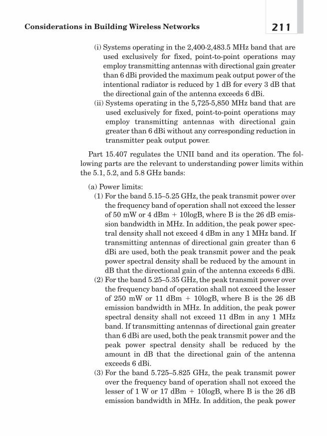
(i) Systems operating in the 2,400–2,483.5 MHz band that areused exclusively for fixed, point-to-point operations mayemploy transmitting antennas with directional gain greaterthan 6 dBi provided the maximum peak output power of theintentional radiator is reduced by 1 dB for every 3 dB thatthe directional gain of the antenna exceeds 6 dBi.
(ii) Systems operating in the 5,725–5,850 MHz band that areused exclusively for fixed, point-to-point operations mayemploy transmitting antennas with directional gaingreater than 6 dBi without any corresponding reduction intransmitter peak output power.
Part 15.407 regulates the UNII band and its operation. The fol-lowing parts are the relevant to understanding power limits withinthe 5.1, 5.2, and 5.8 GHz bands:
(a) Power limits:(1) For the band 5.15—5.25 GHz, the peak transmit power over
the frequency band of operation shall not exceed the lesserof 50 mW or 4 dBm � 10logB, where B is the 26 dB emis-sion bandwidth in MHz. In addition, the peak power spec-tral density shall not exceed 4 dBm in any 1 MHz band. Iftransmitting antennas of directional gain greater than 6dBi are used, both the peak transmit power and the peakpower spectral density shall be reduced by the amount indB that the directional gain of the antenna exceeds 6 dBi.
(2) For the band 5.25—5.35 GHz, the peak transmit power overthe frequency band of operation shall not exceed the lesserof 250 mW or 11 dBm � 10logB, where B is the 26 dBemission bandwidth in MHz. In addition, the peak powerspectral density shall not exceed 11 dBm in any 1 MHzband. If transmitting antennas of directional gain greaterthan 6 dBi are used, both the peak transmit power and thepeak power spectral density shall be reduced by theamount in dB that the directional gain of the antennaexceeds 6 dBi.
(3) For the band 5.725—5.825 GHz, the peak transmit powerover the frequency band of operation shall not exceed thelesser of 1 W or 17 dBm � 10logB, where B is the 26 dBemission bandwidth in MHz. In addition, the peak power
211Considerations in Building Wireless Networks
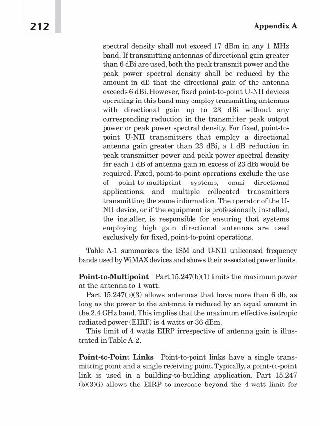
spectral density shall not exceed 17 dBm in any 1 MHzband. If transmitting antennas of directional gain greaterthan 6 dBi are used, both the peak transmit power and thepeak power spectral density shall be reduced by theamount in dB that the directional gain of the antennaexceeds 6 dBi. However, fixed point-to-point U-NII devicesoperating in this band may employ transmitting antennaswith directional gain up to 23 dBi without anycorresponding reduction in the transmitter peak outputpower or peak power spectral density. For fixed, point-to-point U-NII transmitters that employ a directionalantenna gain greater than 23 dBi, a 1 dB reduction inpeak transmitter power and peak power spectral densityfor each 1 dB of antenna gain in excess of 23 dBi would berequired. Fixed, point-to-point operations exclude the useof point-to-multipoint systems, omni directionalapplications, and multiple collocated transmitterstransmitting the same information. The operator of the U-NII device, or if the equipment is professionally installed,the installer, is responsible for ensuring that systemsemploying high gain directional antennas are usedexclusively for fixed, point-to-point operations.
Table A-1 summarizes the ISM and U-NII unlicensed frequencybands used by WiMAX devices and shows their associated power limits.
Point-to-Multipoint Part 15.247(b)(1) limits the maximum powerat the antenna to 1 watt.
Part 15.247(b)(3) allows antennas that have more than 6 db, aslong as the power to the antenna is reduced by an equal amount inthe 2.4 GHz band. This implies that the maximum effective isotropicradiated power (EIRP) is 4 watts or 36 dBm.
This limit of 4 watts EIRP irrespective of antenna gain is illus-trated in Table A-2.
Point-to-Point Links Point-to-point links have a single trans-mitting point and a single receiving point. Typically, a point-to-pointlink is used in a building-to-building application. Part 15.247(b)(3)(i) allows the EIRP to increase beyond the 4-watt limit for
Appendix A212
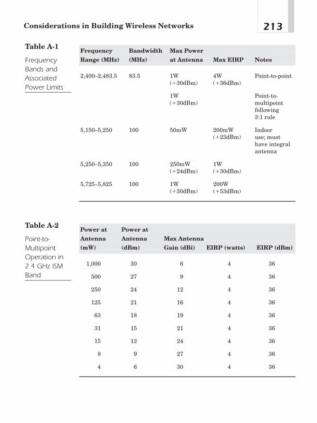
213Considerations in Building Wireless Networks
Frequency Bandwidth Max Power
Range (MHz) (MHz) at Antenna Max EIRP Notes
2,400—2,483.5 83.5 1W 4W Point-to-point(�30dBm) (�36dBm)
1W Point-to-(�30dBm) multipoint
following 3:1 rule
5,150—5,250 100 50mW 200mW Indoor (�23dBm) use; must
have integral antenna
5,250—5,350 100 250mW 1W (�24dBm) (�30dBm)
5,725—5,825 100 1W 200W (�30dBm) (�53dBm)
Table A-1
FrequencyBands andAssociatedPower Limits
Power at Power at
Antenna Antenna Max Antenna
(mW) (dBm) Gain (dBi) EIRP (watts) EIRP (dBm)
1,000 30 6 4 36
500 27 9 4 36
250 24 12 4 36
125 21 16 4 36
63 18 19 4 36
31 15 21 4 36
15 12 24 4 36
8 9 27 4 36
4 6 30 4 36
Table A-2
Point-to-MultipointOperation in2.4 GHz ISMBand
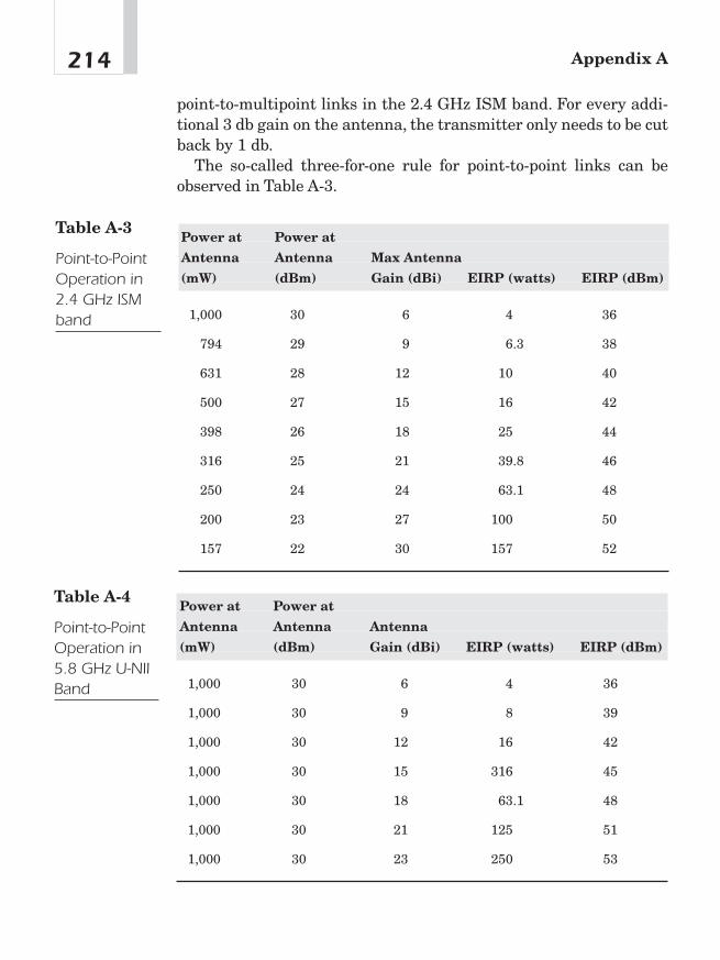
point-to-multipoint links in the 2.4 GHz ISM band. For every addi-tional 3 db gain on the antenna, the transmitter only needs to be cutback by 1 db.
The so-called three-for-one rule for point-to-point links can beobserved in Table A-3.
Appendix A214
Power at Power at
Antenna Antenna Max Antenna
(mW) (dBm) Gain (dBi) EIRP (watts) EIRP (dBm)
1,000 30 6 4 36
794 29 9 6.3 38
631 28 12 10 40
500 27 15 16 42
398 26 18 25 44
316 25 21 39.8 46
250 24 24 63.1 48
200 23 27 100 50
157 22 30 157 52
Table A-3
Point-to-PointOperation in2.4 GHz ISMband
Power at Power at
Antenna Antenna Antenna
(mW) (dBm) Gain (dBi) EIRP (watts) EIRP (dBm)
1,000 30 6 4 36
1,000 30 9 8 39
1,000 30 12 16 42
1,000 30 15 316 45
1,000 30 18 63.1 48
1,000 30 21 125 51
1,000 30 23 250 53
Table A-4
Point-to-PointOperation in5.8 GHz U-NIIBand
According to part 15.247(b)(3)(ii), there is no such restriction inthe 5.8 GHz band. However, part 15.407 effectively restricts theEIRP to 53 dBm. See Table A-4.
Wireless Protocols Preceding WiMAX
Four primary standards-based protocols precede WiMAX: 802.11,802.11b, 802.11a, and 802.11g.
802.11 The 802.11 standard was the first standard to specify theoperation of a WLAN. This standard addresses Frequency HoppingSpread Spectrum (FHSS), Direct Sequence Spread Spectrum(DSSS), and infrared. The data rate is limited to 2 Mb/sec and 1Mb/sec for both FHSS and DSSS.
FHSS handles multipath and narrowband interference as well asa by-product of its frequency-hopping scheme. If multipath fades onechannel, other channels are usually not faded. Thus, packets arepassed on those hops where no fading occurs. Operating an FHSSsystem in a high-multipath or high-noise environment will be seenas an increase in latency. FHSS has 64 hopping patterns, which cansupport up to 15 collocated networks. FHSS systems are limited to 1Mb/sec and optionally 2� Mb/sec. Typically, they have a shorterrange than DSSS systems have. FHSS is not compatible with today’s802.11b equipment.
DSSS as implemented in 802.11 occupies 22 MHz of spectrumwhile providing a maximum over-the-air data rate of 2 Mb/sec. DSSSis susceptible to multipath and narrowband interference due to thelimited amount of spreading that is used (11 bits). DSSS can onlysupport three noninterfering channels and thus does not have nearlyas much network capacity as an FHSS system at the same data rate.DSSS is compatible with today’s 802.11b equipment.
Surplus 802.11 equipment may work well for some applicationswhere multipath immunity is required, lower data rates can be tolerated, and compatibility with currently available equipment isnot desired. Furthermore, be advised that the gear may no longer be covered by warranties and may not have service available for itanymore.
215Considerations in Building Wireless Networks
802.11b The most widely used standard protocol, 802.11b, requiresDSSS technology, specifying a maximum over-the-air data rate of 11Mb/sec and a scheme to reduce the data rate when higher data ratescannot be sustained.This protocol supports 5.5 Mb/sec, 2 Mb/sec, and1 Mb/sec over-the-air data rates in addition to 11 Mb/sec using DSSSand CCK.
IEEE 802.11b standard uses complementary code keying (CCK)as the modulation scheme to achieve data rates of 5 Mb/sec and 11Mb/sec. 802.11 reduced the spreading from 11 bits to 8 to achieve thehigher data rates. The modulation scheme makes up the processinggain lost with the lower spreading by using more forward error cor-rection (FEC).
The IEEE 802.11b specification allows for the wireless transmis-sion of approximately 11 Mbps of raw data at indoor distances toabout 300 feet and outdoor distances of perhaps 20 miles in a point-to-point use of the 2.4 GHz band. The distance depends on impedi-ments, materials, and line-of-sight.
802.11b is the most commonly deployed standard in public short-range networks, such as those found at airports, coffee shops, hotels,conference centers, restaurants, bookstores, and other locations. Sev-eral carriers currently offer pay-as-you-go hourly, per session, orunlimited monthly access, using networks in many locations aroundthe United States and other countries.
802.11a The 802.11a standard operates in the three 5 GHz U-NIIbands and thus is not compatible with 802.11b. The bands are des-ignated by application. The 5.1 GHz band is specified for indoor useonly, the 5.2 GHz band is designated for indoor/outdoor use, and the5.7 GHz band is designated for outdoor only. RF interference is muchless likely because of the less-crowded 5 GHz bands. The 5 GHzbands each have four separate nonoverlapping channels. It specifiesOFDM using 52 subcarriers for interference and multipath avoid-ance; supports a maximum data rate of 54 Mb/sec using 64-QAM;and mandates support of 6, 12, and 24 Mb/sec data rates. The pro-tocol specifies minimum receive sensitivities ranging from �65 dBmfor the 54 Mb/sec rate to �82 dBm for 6 Mb/sec. Equipment designedfor the 5.1 GHz band has an integrated antenna and is not easilymodified for higher power output and operation on the other two 5 GHz bands.
Appendix A216
802.11g 802.11g is an extension to 802.11b and operates in the 2.4GHz band. 802.11g increases 802.11b’s data rates to 54 Mbps usingthe same orthogonal frequency division multiplexing (OFDM) tech-nology that is used in 802.11a. The range at 54 Mbps is less thanexisting 802.11b APs operating at 11 Mbps. As a result, if an 802.11bcell is upgraded to 802.11b, the high data rates will not be availablethroughout all areas. You’ll probably need to add additional APs andreplan the RF frequencies to split the existing cells into smaller ones.802.11g offers higher data rates and more multipath tolerance.Although there is more interference on the 2.4 GHz band, 802.11gmay the protocol of choice for best range and bandwidth combina-tion, and it’s upwardly compatible with 802.11b equipment.
802.11 Summary
Which technique is best? It depends on the application and otherdesign considerations. Frequency hopping offers superior reliabilityin noise and multipath fading environments. Direct sequence canprovide higher over-the-air data rates. OFDM offers multipath toler-ance and much higher data rates. 802.11 (no letter) is now obsoletebut may offer nonstandard, bargain-basement, usable equipment.802.11b is compatible with most of the public access locations.802.11a is the best to solve interference cases and has great through-put. 802.11g promises the best range and throughput combination ofall the solutions.
PlanningA link budget will tell what is practical given the environment andhow to plan cells. With a link budget, one can estimate how manycells will be required for the project. There are trade-offs betweenmore cells and running more power. For an outdoor application, alsoconsider checking the Fresnel zone. For example, the trade-offbetween working on one long-distance shot versus two back-to-backlinks can be discovered by working out a few things on paper first.
217Considerations in Building Wireless Networks

Fresnel Zone
For a point-to-point shot, it is important to understand the effects ofthe Fresnel zone. The signal extending from the transmittingantenna forms an ever-expanding cone. Although some of the signaltravels directly in the line of sight along the center of the cone, otherparts of the signal reradiate off of points along the way. At thereceiver, signals from the direct line of sight indirectly cancel andadd to each other. The first Fresnel zone is the surface containingevery point for which the sum of the distances from that point to thetwo ends of the path is exactly 1/2 wavelength longer than the directend-to-end path. The second Fresnel zone is the surface containingevery point for which the sum of the distances from that point to thetwo ends of the path is exactly one wavelength longer than the directend-to-end path. Figure A-4 shows the first and second Fresnelzones.
One can calculate the perpendicular distance of the Fresnel zonefrom the line that connects the transmitter and the receiver usingthe following Nth Fresnel zone formula:
Appendix A218
2
1
D2D1
F1
Figure A-4First and secondFresnel zones

Where:N is the Fresnel zone number, N � 1 is the first Fresnel
zone
l is the wavelength [meters]
D1 and D2 are the distances to the endpoints [meters]
If there are reflections of the signal from the odd number Fresnelzone, the signal level will cancel at the receiver, but if the reflectionis from an even number Fresnel zone, it will add at the receiver.Therefore, on long-distance shots, it is necessary to take into accountground/water reflections and vertical surfaces such as tall buildings.
Because the majority of the transmitted power is in the first Fres-nel zone, any time the path clearance between the terrain and theline-of-sight path is less than 0.6F1 (six-tenths of the first Fresnelzone distance), some knife-edge diffraction loss will occur. Theamount of loss depends on the amount of penetration. To find out ifthere is any building or obstruction in the Fresnel zone, a profile ofthe terrain is superimposed with the ellipse created by the Nth Fres-nel zone formula with the first Fresnel zone (N � 1) and the resultis multiplied by 0.6 for repetitive points across the profile.
Signal strength is possibly gained at the receiver up to 3 dB byhaving a flat surface such as a lake, a highway, or a smooth desertarea at the second Fresnel zone in such a way that the signals get re-enforced at the receiver.
Decibels and Signal Strength Rather than tracking all thosezeroes, amplifier power is measured in a logarithmic scale—decibels(dB). Then instead of multiplying and dividing all the gains, it’smuch simpler to add and subtract dBs.
dB � 10 � logl0 (power out/power in)
Decibel readings are positive when the output is larger than theinput and negative when the output is smaller than the input. Each10 dB change corresponds to a factor of 10, and 3 dB changes are afactor of 2. Thus, a 33 dB change corresponds to a factor of | 2,000:
33dB � 10dB � 10dB � 10dB � 3dB � 10 � 10 � 10 � 2 � 2,000
219Considerations in Building Wireless Networks

Power is sometimes measured in dBm, which stands for dBabove one milliwatt. To find the dBm ratio, simply use 1 mW as theinput in the first equation. It’s helpful to remember that doublingthe power is a 3 dB increase. A 1 dB increase is roughly equivalentto a power increase of 1.25. And a 10 dB increase in power is a 10times power increase. With these numbers in mind, you can quicklyperform most gain calculations in your head.
How to Calculate a Link Budget
Link budget planning is an essential part of the network planningprocess for both indoor and outdoor applications. A link budget helpsto give dimension to the required coverage, capacity, and quality ofservice requirement in the network. In a typical WiMAX link, thereare two link budget calculations: one link from the BS to the SS andthe other link from the SS to the BS. Link budgets can be used todetermine if the link design meets the designer’s criteria for range,throughput, and BER.
A link budget basically adds all the gains and losses to the trans-mitter power (in dB) to yield the received power. In order to haveadequate signal at the receiver, the power presented to the receivermust be at least as much as the receive sensitivity. The link budgetfor the AP to the client adapter card is shown in Figure A-5.
Transmit PowerTransmitter output power—legal limits
Transmit antenna gain—legal limits
Appendix A220
AccessPoint
Access PointAntenna
Network Interface CardAntenna
Laptop computer
Figure A-5Calculating alink budget

Path Loss The most difficult part of calculating a link budget isthe path loss. Outdoors, the free-space loss is well understood. Thepath loss equation2 for outdoors can be expressed as:
Free Space Path Loss �20 log (d [meters]) � 20 log (f [MHz]) � 36.6 dB
At 2.4 GHz, the formula simplifies to:
Free Space Path Loss � 20 log (d [meters]) � 40 dB
This formula holds true as long as one can see along the line-of-sight from the receiver to the transmitter and have a sufficientamount of area around that path called the Fresnel zone. Forindoors, this formula is more complicated and depends on factorssuch as building materials, furniture, and occupants.
At 2.4 GHz, one estimate follows this formula:
Indoor Path Loss (2.4 GHz) � 55 dB � 0.3 dB / d [meters]
At 5.7 GHz, the formula looks like this:
Indoor Path Loss (5.7 GHz) � 63 dB � 0.3 dB / d [meters]
Receive Antenna Gain The receive antenna, like the transmitantenna, adds gain into the link budget. Adding gain to an antennais balanced gain because it adds gain for both transmit and receive.
Link Margin Fade margin is the difference, in dB, between themagnitude of the received signal at the receiver input and the min-imum level of signal determined for reliable operation. Links withhigher fade margins are more reliable. The exact amount of fademargin required depends on the desired reliability of the link, but agood rule-of-thumb is 20 to 30 dB
221Considerations in Building Wireless Networks
2Edward C. Jordan, Reference Data for Engineers: Radio, Electronics, Computer, andCommunications (Indianapolis: Howard W. Sams and Co., 1986).
Fade margin is often referred to as “thermal” or “system operatingmargin.”
Diffraction Losses Diffraction occurs when the radio pathbetween the transmitter and receiver is obstructed by a surface thathas sharp irregularities or edge. The secondary waves resulting fromthe obstructing surface are present behind the obstacle. On close toline of sight, diffraction losses can be as little as 6 dB. On non-line-of-sight obstacles, diffraction losses can be 20 to 40 dB.
Coax and Connector Losses Connector losses can be estimatedat 0.5 dB per connection. Cable losses are a function of cable type,thickness, and length. Generally speaking, thicker and better-builtcables have lower losses (and higher costs). As can be seen fromTable A-5, coax losses are nearly prohibitive in the 2.4 and 5.8 GHzbands. The best option is to minimize cable loss and locate themicrowave transceiver as close to the antenna as possible in an envi-ronmental enclosure.
Attenuation Earlier wireless technologies have been hamperedby rain and fog. Wi-Fi and WiMAX are considerably better at deal-ing with rain fades and other atmospheric degradations.
Rain and Fog When deploying in a rainy or foggy climate, it may benecessary to plan for additional signal loss due to rain or fog. Forexample, 2.4 GHz signals may be attenuated by up to 0.05 dB/km(0.08 dB/mile) by heavy rain (4 inches/hr). Thick fog produces up to0.02 dB/km (0.03 dB/mile) attenuation. At 5.8 GHz, heavy rain mayproduce up to 0.5 dB/km (0.8 dB/mile) attenuation, and thick fogmay produce up to 0.07 dB/km (0.11 dB/mile). Even though rainitself does not cause major propagation problems, rain will collect onthe leaves of trees and will produce attenuation until it evaporates.
Appendix A222
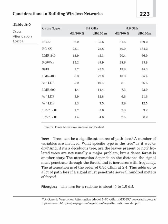
Trees Trees can be a significant source of path loss.3 A number ofvariables are involved: What specific type is the tree? Is it wet ordry? And, if it’s a deciduous tree, are the leaves present or not? Iso-lated trees are not usually a major problem, but a dense forest isanother story. The attenuation depends on the distance the signalmust penetrate through the forest, and it increases with frequency.The attenuation is of the order of 0.35 dB/m at 2.4. This adds up toa lot of path loss if a signal must penetrate several hundred metersof forest!
Fiberglass The loss for a radome is about .5 to 1.0 dB.
223Considerations in Building Wireless Networks
Cable Type 2.4 GHz 5.8 GHz
dB/100 ft dB/100 m dB/100 ft dB/100m
RG-58 32.2 105.6 51.6 169.2
RG-8X 23.1 75.8 40.9 134.2
LMR-240 12.9 42.3 20.4 66.9
RG213/214 15.2 49.9 28.6 93.8
9913 7.7 25.3 13.8 45.3
LMR-400 6.8 22.3 10.8 35.4
3/8 " LDF 5.9 19.4 8.1 26.6
LMR-600 4.4 14.4 7.3 23.9
1/2 " LDF 3.9 12.8 6.6 21.6
7/8 " LDF 2.3 7.5 3.8 12.5
1 1/4 " LDF 1.7 5.6 2.8 9.2
1 5/8 " LDF 1.4 4.6 2.5 8.2
(Source: Times Microwave, Andrew and Belden)
Table A-5
CoaxAttenuationLosses
3 “A Generic Vegetation Attenuation Model 1—60 GHz: PM3035,” www.radio.gov.uk/topics/research/topics/propagation/vegetation/veg-attenuation-model.pdf.

Glass A normal, clear glass pane will lose about 3 dB at 2.4 GHz.Although most glass will not affect radio frequency, certain kinds ofglass severely attenuate signals.4 It depends on the glass and thetint material. If the glass is at all reflective on either side, chancesare that a signal may not be able to penetrate it. New constructionoften uses tinted, coated, or High-E glass that is designed to holdheat out, and this glass attenuates 802.11 and 802.16 signals.Although High-E glass is not necessarily tinted, it is energy-efficientand is usually double paned, coated, and filled with argon or otherinert gasses. Tin oxide (SnO2) coatings do not pass RF. Some win-dows have as much as 20 dB loss. Note: Removing external tintingwith a razor blade may allow RF to pass through the glass.
Other Building Materials Examples of attenuation through variousbuilding materials are shown in Table A-6.5
Appendix A224
4“Glass That Cuts Signals,” www.isp-planet.com/fixed_wireless/technology/2001/tint_bol.html.5John C. Stein, “Indoor Radio WLAN Performance Part II Range Performance in aDense Office Environment,” Intersil Corp., 1997, available online at http://whitepapers.silicon.com/0,39024759,60016337p-39000370q,00.htm.
Material Attenuation
Window Brick Wall 2 dB
Metal Frame Glass Wall into Building 6 dB
Office Wall 6 dB
Metal Door in Office Wall 6 dB
Cinder Block Wall 4 dB
Metal Door in Brick Wall 12.4 dB
Brick Wall next to Metal Door 3 dB
Table A-6
Attenuation ofVariousBuildingMaterials
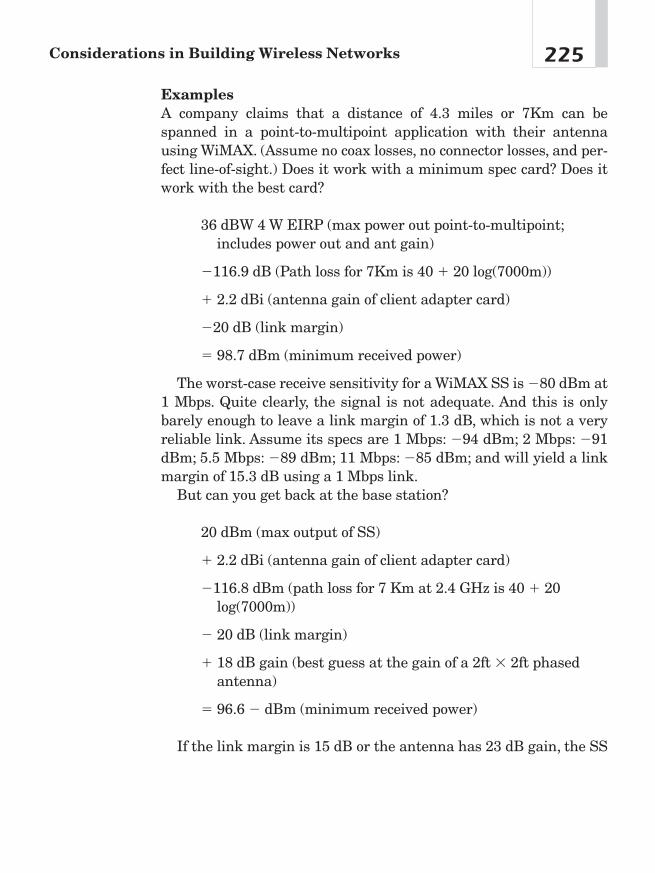
ExamplesA company claims that a distance of 4.3 miles or 7Km can bespanned in a point-to-multipoint application with their antennausing WiMAX. (Assume no coax losses, no connector losses, and per-fect line-of-sight.) Does it work with a minimum spec card? Does itwork with the best card?
36 dBW 4 W EIRP (max power out point-to-multipoint;includes power out and ant gain)
�116.9 dB (Path loss for 7Km is 40 � 20 log(7000m))
� 2.2 dBi (antenna gain of client adapter card)
�20 dB (link margin)
� 98.7 dBm (minimum received power)
The worst-case receive sensitivity for a WiMAX SS is �80 dBm at1 Mbps. Quite clearly, the signal is not adequate. And this is onlybarely enough to leave a link margin of 1.3 dB, which is not a veryreliable link. Assume its specs are 1 Mbps: �94 dBm; 2 Mbps: �91dBm; 5.5 Mbps: �89 dBm; 11 Mbps: �85 dBm; and will yield a linkmargin of 15.3 dB using a 1 Mbps link.
But can you get back at the base station?
20 dBm (max output of SS)
� 2.2 dBi (antenna gain of client adapter card)
�116.8 dBm (path loss for 7 Km at 2.4 GHz is 40 � 20log(7000m))
� 20 dB (link margin)
� 18 dB gain (best guess at the gain of a 2ft � 2ft phasedantenna)
� 96.6 � dBm (minimum received power)
If the link margin is 15 dB or the antenna has 23 dB gain, the SS
225Considerations in Building Wireless Networks

can be heard at 7Km with this antenna.Given current technology, what is the best you can do on a point-
to-point link?
■ Get more transmit power and better receive sensitivity.
■ Remove noise.
■ Limit any attenuation from the link budget.
■ Get antennas with the most gain for both ends.
■ Go to a lower data rate—better sensitivity (higher data rate �less power efficiency).
■ Use two antennas for diversity at both ends.
Assume an SS to have output power at 100 mW or 20 dBm and avery sensitive receiver at �85 dBm at 11 mbps.
If you now go to a lower data rate, for example 1 Mbps, the receivesensitivity is at �94 dBm. A link budget for a record-breaking point-to-point link looks like this:
24 dBm (max legal output of transmitter)
� 24 dBi (grid antenna gain)
� 20 dB (link margin)
� 2 dB (connector losses)
� 2 dB (coax losses)
� 24 dB gain (grid antenna gain)
� 94 dBm (minimum received power at 1 mbps)
� maximum path loss � 142 dbm
or about 75 miles [path loss for 120 Km at 2.4 GHz is 40 � 20log(120,000m)]
Under full multipath conditions, this link will have a 1 megabitdata rate. Under better conditions, the link may operate at the fulldata rate of 11 Mbps.
Appendix A226
Site Survey
Once things work on paper with an adequate link budget and theFresnel zone, one can go out to the site and see if the paper planworks.
Outdoor Site Survey All the data on paper may indicate thateverything will work for a particular link—the link budget, the Fres-nel zone can be checked against a topographical view of the point-to-point shot. You may even have used expensive ray-tracingprograms to predict the path, but there is only one way to learn ifthe installation will work.
To perform an outdoor site survey for a point-to-point shot, takealong binoculars, two-way radios or cell phones, topographical maps,a GPS, a spectrum analyzer, an inexpensive dB attenuator, and radioequipment to take the trial shot. Have a friend go to the other hilland talk to you on the radio.
Drive out to the proposed site and see with the binoculars if theshot is clear. Check for trees or buildings that may have grown up inthe path. The best time to plan a long-distance shot is during springwhen everything is wet and growing. If it’s the dead of winter,remember that the trees will soon grow leaves again.
Using the location of both endpoints, calculate a bearing and tiltangle to point the antenna. Most GPSs have a built-in function to dothis. High-gain dishes are more difficult to aim the further out yougo. Take both dishes and point them roughly toward each other.Transmit a signal into one dish.With WiMAX gear, link test softwareallows you to send a series of management frames.
You can take the output of the other dish and feed it into the spec-trum analyzer. You will see a display of frequency (across) versusamplitude (up and down). Pick the channel that has the leastamount of noise.
Once you get the antennas close, you will see a spike on the fre-quency the transmitting dish is tuned to; this spike will be sur-rounded by noise. Sweep the antenna on each end one at a time, andlock-down the antenna at the point where the signal is the strongest.
227Considerations in Building Wireless Networks
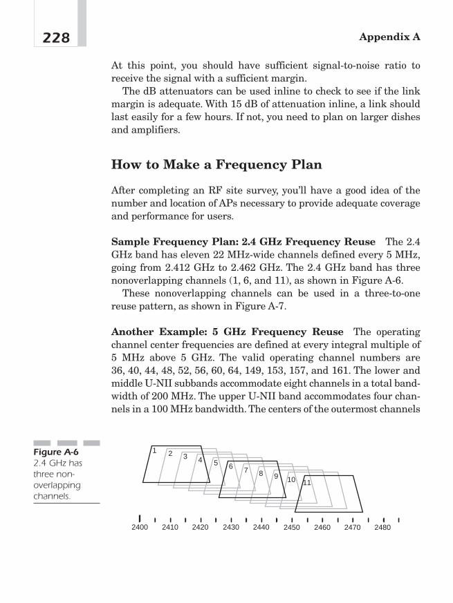
At this point, you should have sufficient signal-to-noise ratio toreceive the signal with a sufficient margin.
The dB attenuators can be used inline to check to see if the linkmargin is adequate. With 15 dB of attenuation inline, a link shouldlast easily for a few hours. If not, you need to plan on larger dishesand amplifiers.
How to Make a Frequency Plan
After completing an RF site survey, you’ll have a good idea of thenumber and location of APs necessary to provide adequate coverageand performance for users.
Sample Frequency Plan: 2.4 GHz Frequency Reuse The 2.4GHz band has eleven 22 MHz-wide channels defined every 5 MHz,going from 2.412 GHz to 2.462 GHz. The 2.4 GHz band has threenonoverlapping channels (1, 6, and 11), as shown in Figure A-6.
These nonoverlapping channels can be used in a three-to-onereuse pattern, as shown in Figure A-7.
Another Example: 5 GHz Frequency Reuse The operatingchannel center frequencies are defined at every integral multiple of5 MHz above 5 GHz. The valid operating channel numbers are 36, 40, 44, 48, 52, 56, 60, 64, 149, 153, 157, and 161. The lower andmiddle U-NII subbands accommodate eight channels in a total band-width of 200 MHz. The upper U-NII band accommodates four chan-nels in a 100 MHz bandwidth. The centers of the outermost channels
Appendix A228
1 2 3 4 5 6 7 8 9 10 11
2400 2410 2420 2430 2440 2450 2460 2470 2480
Figure A-62.4 GHz hasthree non-overlappingchannels.
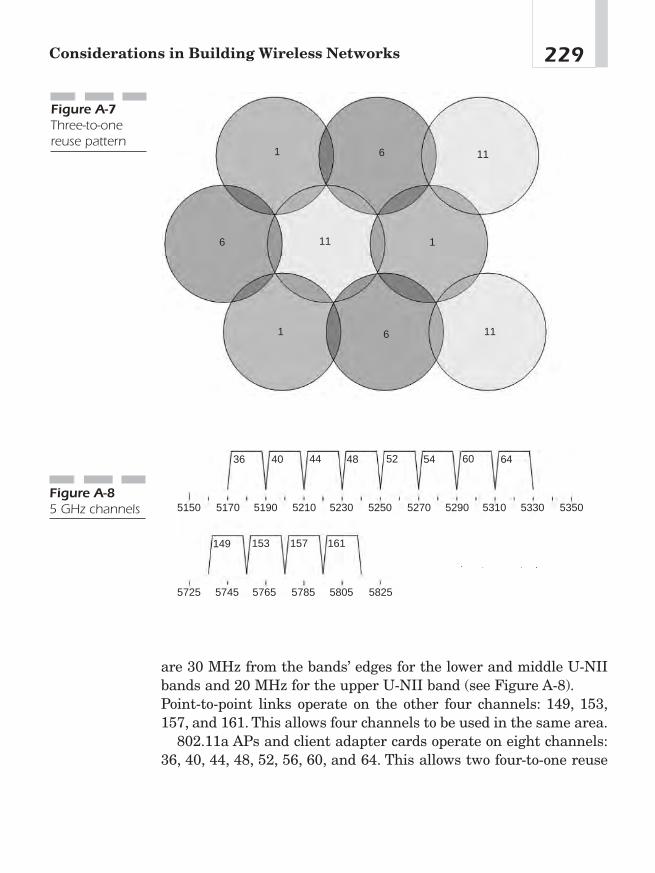
are 30 MHz from the bands’ edges for the lower and middle U-NIIbands and 20 MHz for the upper U-NII band (see Figure A-8).Point-to-point links operate on the other four channels: 149, 153,157, and 161. This allows four channels to be used in the same area.
802.11a APs and client adapter cards operate on eight channels:36, 40, 44, 48, 52, 56, 60, and 64. This allows two four-to-one reuse
229Considerations in Building Wireless Networks
1
1
1
6
6
6
11
11
11
Figure A-7Three-to-onereuse pattern
5150 5170 5190 5210 5230 5250 5270 5290 5310 5330 5350
5725 5745 5765 5785 5805 5825
36 40 44 48 52 54 60 64
149 153 157 161
Figure A-85 GHz channels
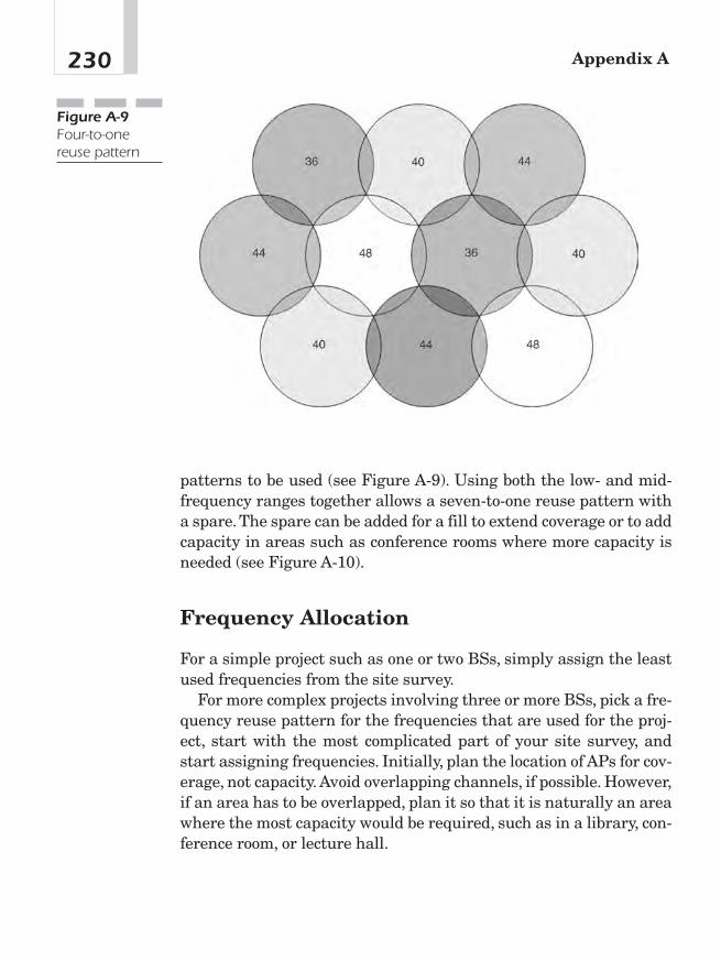
patterns to be used (see Figure A-9). Using both the low- and mid-frequency ranges together allows a seven-to-one reuse pattern witha spare. The spare can be added for a fill to extend coverage or to addcapacity in areas such as conference rooms where more capacity isneeded (see Figure A-10).
Frequency Allocation
For a simple project such as one or two BSs, simply assign the leastused frequencies from the site survey.
For more complex projects involving three or more BSs, pick a fre-quency reuse pattern for the frequencies that are used for the proj-ect, start with the most complicated part of your site survey, andstart assigning frequencies. Initially, plan the location of APs for cov-erage, not capacity. Avoid overlapping channels, if possible. However,if an area has to be overlapped, plan it so that it is naturally an areawhere the most capacity would be required, such as in a library, con-ference room, or lecture hall.
Appendix A230
Figure A-9Four-to-onereuse pattern

Equipment SelectionThe following paragraphs do not necessarily constitute a buyer’sguide, but rather a guide to reading a vendor’s spec sheet for radiosand antennas.
How to Look at Specs
Perhaps the most important spec to consider when looking for wire-less equipment is receive sensitivity. This is signal strength requiredfor the card to overcome channel noise. Better receiving (a lower dB
231Considerations in Building Wireless Networks
Figure A-10Seven-to-onereuse patternwith a spare
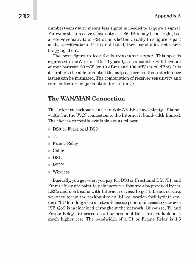
number) sensitivity means less signal is needed to acquire a signal.For example, a receive sensitivity of �86 dBm may be all right, buta receive sensitivity of �91 dBm is better. Usually this figure is partof the specifications. If it is not listed, then usually it’s not worthbragging about.
The next figure to look for is transmitter output. This spec isexpressed in mW or in dBm. Typically, a transmitter will have anoutput between 20 mW (or 13 dBm) and 100 mW (or 20 dBm). It isdesirable to be able to control the output power so that interferenceissues can be mitigated. The combination of receiver sensitivity andtransmitter are major contributors to range.
The WAN/MAN Connection
The Internet backbone and the WiMAX BSs have plenty of band-width, but the WAN connection to the Internet is bandwidth-limited.The choices currently available are as follows:
■ DS3 or Fractional DS3
■ T1
■ Frame Relay
■ Cable
■ DSL
■ ISDN
■ Wireless
Basically, you get what you pay for. DS3 or Fractional DS3,T1, andFrame Relay are point-to-point services that are also provided by theLECs and don’t come with Internet service. To get Internet service,you need to run the backhaul to an ISP, collocation facility/data cen-ter, a “lit” building or to a network access point and become your ownISP. QoS is maintained throughout the network. Of course, T1 andFrame Relay are priced as a business and thus are available at amuch higher cost. The bandwidth of a T1 or Frame Relay is 1.5
Appendix A232
Mbps. Fractional DS3 is an aggregate of several T1s. Bandwidth ismultiples of 1.5 Mbps up to 45 Mbps. It’s priced accordingly. Themore bandwidth one contracts to buy, the lower the price per 1.5Mbps increments. Some vendors will also sell by the Mbps.
Antennas Antennas offer another way to increase the range.Antennas limit energy directed in certain areas and redirect theenergy in other areas. All antennas exhibit this to a certain extent.A theoretical antenna point source called isotropic is used as a ref-erence for all other antennas. Thus, the gain of an antenna is mea-sured in terms of dBi or decibels over isotropic. Omnidirectionalantennas generally have between 2 and 10 dBi, whereas directionalantennas can have between 3 and 25 dBi of gain.
FCC regulations limit how much gain a transmitting antenna canhave. But antennas have two distinct advantages over amplifiers.First, an antenna offers gains in both the transmit side and thereceive side. Thus, the impact on the link budget is balanced. Second,antennas help the interference problem. The transmitter only trans-mits the signal where it is needed, and the receiver only listenswhere the antenna is pointed. Not transmitting where other usersare and receiving more of the intended signal and less of the inter-fering station (unless, of course, the interfering station is located inthe same antenna path as the intended station) limits interference.
Antennas—BS Side It all starts at the base station. The base sta-tion antenna is not the place to economize.
Omnidirectional Omnidirectional antennas transmit their signalroughly equally in all horizontal directions.The radiation pattern hasthe shape of a large donut around the vertical axis as in Figure A-11.
The gain is in the horizontal direction at the expense of coverageabove and below the antenna. For more gain or an outdoor omnidi-rectional antenna, consider a collinear antenna. Typically, a collinearomnidirectional antenna looks like a PVC pipe that is between 1 and 5 feet tall and has an N connector at the end (see Figure A-12).Gain for these antennas is between 3 and 12 dBi.
233Considerations in Building Wireless Networks
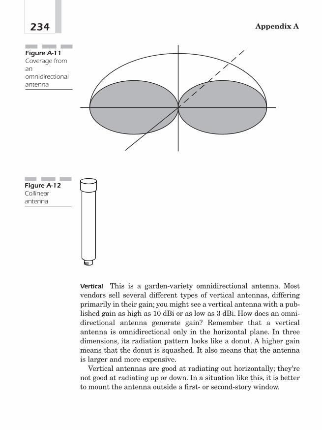
Vertical This is a garden-variety omnidirectional antenna. Mostvendors sell several different types of vertical antennas, differingprimarily in their gain; you might see a vertical antenna with a pub-lished gain as high as 10 dBi or as low as 3 dBi. How does an omni-directional antenna generate gain? Remember that a verticalantenna is omnidirectional only in the horizontal plane. In threedimensions, its radiation pattern looks like a donut. A higher gainmeans that the donut is squashed. It also means that the antennais larger and more expensive.
Vertical antennas are good at radiating out horizontally; they’renot good at radiating up or down. In a situation like this, it is betterto mount the antenna outside a first- or second-story window.
Appendix A234
Figure A-12Collinearantenna
Figure A-11Coverage fromanomnidirectionalantenna
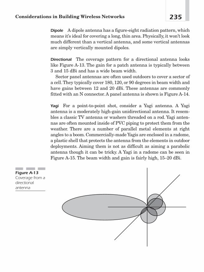
Dipole A dipole antenna has a figure-eight radiation pattern, whichmeans it’s ideal for covering a long, thin area. Physically, it won’t lookmuch different than a vertical antenna, and some vertical antennasare simply vertically mounted dipoles.
Directional The coverage pattern for a directional antenna lookslike Figure A-13. The gain for a patch antenna is typically between3 and 15 dBi and has a wide beam width.
Sector panel antennas are often used outdoors to cover a sector ofa cell. They typically cover 180, 120, or 90 degrees in beam width andhave gains between 12 and 20 dBi. These antennas are commonlyfitted with an N connector. A panel antenna is shown is Figure A-14.
Yagi For a point-to-point shot, consider a Yagi antenna. A Yagiantenna is a moderately high-gain unidirectional antenna. It resem-bles a classic TV antenna or washers threaded on a rod. Yagi anten-nas are often mounted inside of PVC piping to protect them from theweather. There are a number of parallel metal elements at rightangles to a boom. Commercially-made Yagis are enclosed in a radome,a plastic shell that protects the antenna from the elements in outdoordeployments. Aiming them is not as difficult as aiming a parabolicantenna though it can be tricky. A Yagi in a radome can be seen inFigure A-15. The beam width and gain is fairly high, 15—20 dBi.
235Considerations in Building Wireless Networks
Figure A-13Coverage from adirectionalantenna
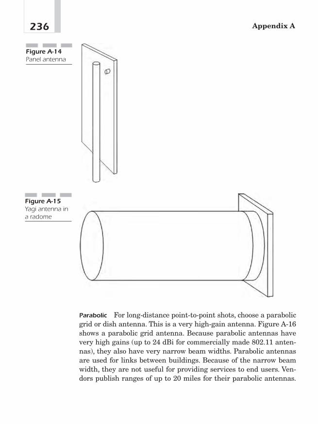
Parabolic For long-distance point-to-point shots, choose a parabolicgrid or dish antenna. This is a very high-gain antenna. Figure A-16shows a parabolic grid antenna. Because parabolic antennas havevery high gains (up to 24 dBi for commercially made 802.11 anten-nas), they also have very narrow beam widths. Parabolic antennasare used for links between buildings. Because of the narrow beamwidth, they are not useful for providing services to end users. Ven-dors publish ranges of up to 20 miles for their parabolic antennas.
Appendix A236
Figure A-15Yagi antenna ina radome
Figure A-14Panel antenna
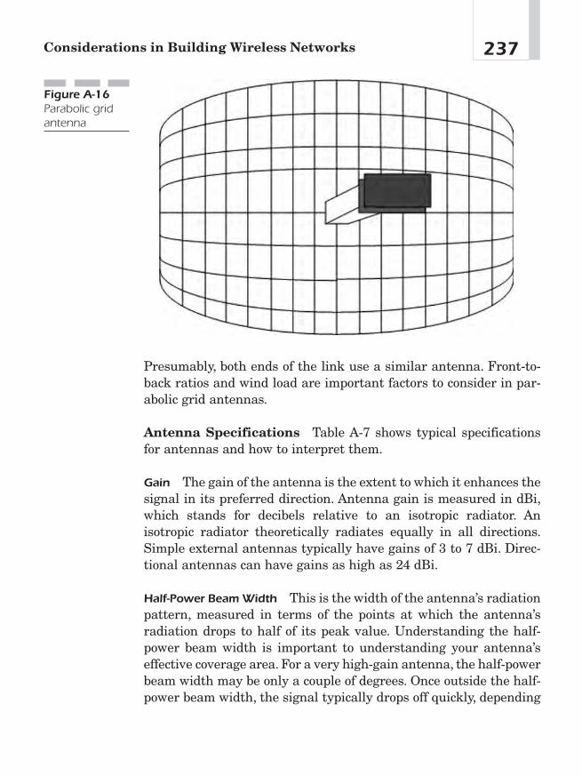
237Considerations in Building Wireless Networks
Figure A-16Parabolic gridantenna
Presumably, both ends of the link use a similar antenna. Front-to-back ratios and wind load are important factors to consider in par-abolic grid antennas.
Antenna Specifications Table A-7 shows typical specificationsfor antennas and how to interpret them.
Gain The gain of the antenna is the extent to which it enhances thesignal in its preferred direction. Antenna gain is measured in dBi,which stands for decibels relative to an isotropic radiator. Anisotropic radiator theoretically radiates equally in all directions.Simple external antennas typically have gains of 3 to 7 dBi. Direc-tional antennas can have gains as high as 24 dBi.
Half-Power Beam Width This is the width of the antenna’s radiationpattern, measured in terms of the points at which the antenna’sradiation drops to half of its peak value. Understanding the half-power beam width is important to understanding your antenna’seffective coverage area. For a very high-gain antenna, the half-powerbeam width may be only a couple of degrees. Once outside the half-power beam width, the signal typically drops off quickly, depending
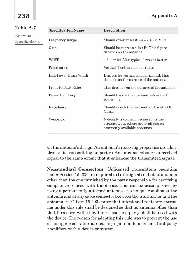
Appendix A238
Specification Name Description
Frequency Range Should cover at least 2.4 — 2.4835 MHz.
Gain Should be expressed in dBi. This figure depends on the antenna.
VSWR 1.5:1 or 2:1 Max typical; lower is better.
Polarization Vertical, horizontal, or circular.
Half-Power Beam Width Degrees for vertical and horizontal. This depends on the purpose of the antenna.
Front-to-Back Ratio This depends on the purpose of the antenna.
Power Handling Should handle the transmitter’s output power � 3.
Impedance Should match the transmitter. Usually 50 Ohms.
Connector N-female is common because it is the strongest, but others are available on commonly available antennas.
Table A-7
AntennaSpecifications
on the antenna’s design. An antenna’s receiving properties are iden-tical to its transmitting properties. An antenna enhances a receivedsignal to the same extent that it enhances the transmitted signal.
Nonstandard Connectors Unlicensed transmitters operatingunder Section 15.203 are required to be designed so that no antennaother than the one furnished by the party responsible for certifyingcompliance is used with the device. This can be accomplished byusing a permanently attached antenna or a unique coupling at theantenna and at any cable connector between the transmitter and theantenna. FCC Part 15.203 states that intentional radiators operat-ing under this rule shall be designed so that no antenna other thanthat furnished with it by the responsible party shall be used withthe device. The reason for adopting this rule was to prevent the useof unapproved, aftermarket high-gain antennas or third-partyamplifiers with a device or system.
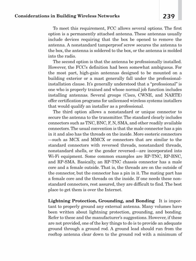
To meet this requirement, FCC allows several options. The firstoption is a permanently attached antenna. These antennas usuallyinclude devices requiring that the box be opened to remove theantenna. A nonstandard tamperproof screw secures the antenna tothe box, the antenna is soldered to the box, or the antenna is moldedinto the radio.
The second option is that the antenna be professionally installed.However, the FCC’s definition had been somewhat ambiguous. Forthe most part, high-gain antennas designed to be mounted on abuilding exterior or a mast generally fall under the professional-installation clause. It’s generally understood that a “professional” isone who is properly trained and whose normal job function includesinstalling antennas. Several groups (Cisco, CWNE, and NARTE)offer certification programs for unlicensed wireless systems installersthat would qualify an installer as a professional.
The third option allows a nonstandard or unique connector tosecure the antenna to the transmitter. The standard clearly includesconnectors such as TNC, BNC, F, N, SMA, and other readily availableconnectors.The usual convention is that the male connector has a pinin it and also has the threads on the inside. More esoteric connectors—such as MCX and MMCX or connectors that are similar to thestandard connectors with reversed threads, nonstandard threads,nonstandard shells, or the gender reversed—are incorporated intoWi-Fi equipment. Some common examples are RP-TNC, RP-BNC,and RP-SMA. Basically, an RP-TNC chassis connector has a malecore and a female outside. That is, the threads are on the outside ofthe connector, but the connector has a pin in it. The mating part hasa female core and the threads on the inside. If one needs these non-standard connectors, rest assured, they are difficult to find. The bestplace to get them is over the Internet.
Lightning Protection, Grounding, and Bonding It is impor-tant to properly ground any external antenna. Many volumes havebeen written about lightning protection, grounding, and bonding.Refer to these and the manufacturer’s suggestions. However, if theseare not provided, one of the key things to do is to provide an adequateground through a ground rod. A ground lead should run from therooftop antenna clear down to the ground rod with a minimum of
239Considerations in Building Wireless Networks
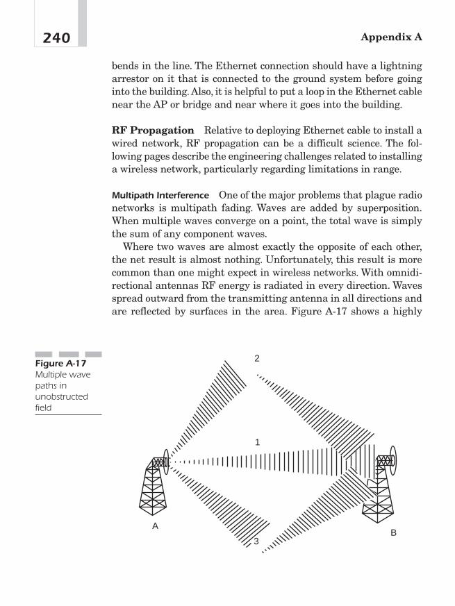
bends in the line. The Ethernet connection should have a lightningarrestor on it that is connected to the ground system before goinginto the building.Also, it is helpful to put a loop in the Ethernet cablenear the AP or bridge and near where it goes into the building.
RF Propagation Relative to deploying Ethernet cable to install awired network, RF propagation can be a difficult science. The fol-lowing pages describe the engineering challenges related to installinga wireless network, particularly regarding limitations in range.
Multipath Interference One of the major problems that plague radionetworks is multipath fading. Waves are added by superposition.When multiple waves converge on a point, the total wave is simplythe sum of any component waves.
Where two waves are almost exactly the opposite of each other,the net result is almost nothing. Unfortunately, this result is morecommon than one might expect in wireless networks. With omnidi-rectional antennas RF energy is radiated in every direction. Wavesspread outward from the transmitting antenna in all directions andare reflected by surfaces in the area. Figure A-17 shows a highly
Appendix A240
1
3B
A
2Figure A-17Multiple wavepaths inunobstructedfield

simplified example of two stations in a rectangular area with noobstructions.
Figure A-18 shows three paths from the transmitter to thereceiver. The wave at the receiver is the sum of all the different com-ponents. It is certainly possible that the paths shown in this figurewill all combine to give a net wave of 0, in which case the receiverwill not understand the transmission because there is no transmis-sion to be received.
Because the interference is a delayed copy of the same transmis-sion on a different path, the phenomenon is called multipath fadingor multipath interference. In many cases, multipath interference canbe resolved by changing the orientation or position of the receiver.
Intersymbol Interference (ISI) Multipath fading is a special case ofISI. Waves that take different paths from the transmitter to thereceiver will travel different distances and will be delayed withrespect to each other, as shown in Figure A-18. Once again, the twowaves combine by superposition, but the effect is that the total wave-form is garbled. In real-world situations, wavefronts from multiplepaths may be added. The time between the arrival of the first wave-front and the last multipath echo is called the delay spread. Longerdelay spreads require more conservative coding mechanisms.802.11b networks can handle delay spreads of up to 500 ns, but per-formance is much better when the delay spread is lower. When thedelay spread is large, many cards will reduce the transmission rate;
241Considerations in Building Wireless Networks
Figure A-18ISI

several vendors claim that a 65 ns delay spread is required for full-speed 11 Mbps performance at a reasonable frame error rate. A fewwireless LAN analysis tools can directly measure delay spread.6
Using Two Antennas for Diversity Diversity is often used withcellular BSs and is seen to help overcome multipath problems. SomeBSs have two antenna connectors for diversity.
Anyone who listens to the car radio while driving in a downtownurban environment has experienced a momentary dropout or fadingof the radio station at a stoplight. If the car moves forward or back-ward ever so slightly, the station comes back in. Although the car isin range of the radio tower, no signal is received in these dead spots.This phenomenon is called multipath fading and is the result of mul-tiple signals from different paths canceling at the receiver antenna.Figure A-19 shows multipath cancellation from a large building.
Five different types of diversity can be used to increase signalreception in the presence of multipath fading: temporal, frequency,spatial, polarization, and angular. The first two types of diversityrequire changes in hardware.
Temporal diversity involves lining up and comparing multiple sig-nals and choosing the one that best matches the expected time ofarrival for a signal.This concept is implemented in some digital tech-nologies. One of the most common methods to do this is adaptiveequalization and RAKE receivers.
Appendix A242
Reflected Path
Direct
Path
Figure A-19Multipathcancellation
6Ibid., 158—163.

Frequency diversity can be implemented by using two separateradio links on two different channels. If there is a null due to the can-cellation of two signals because of a reflection, it will not happen onanother frequency at the same place. Routers at both ends of the linkcould be used to send data across both wireless links. If one fails dueto fading, the effective throughput is decreased. The redundancy ofthe link would also provide protection for other cases of failure.
Spatial diversity helps overcome the multipath problem by usingtwo identical receive antennas separated by a fixed number of wave-lengths. If there is a null due to a cancellation of the two signals, itwill not happen at the other antenna. Because the antenna with thestrongest signal is selected, the link is more likely to survive a fadewhen using spatial diversity.
The multipath problem can be helped with antennas mounted atdifferent angles to cover the same coverage area. If a signal from oneantenna and its reflection is cancelled, then a signal from a differentantenna arriving at a slightly different angle will probably not can-cel because the phase has changed. Again, because the antenna withthe strongest signal is selected, the link is more likely to survive afade when using angular diversity.
Finally, transmitting and receiving using two feed horns usingboth vertical and horizontal polarization (or clockwise and counter-clockwise polarization) can also mitigate the multipath problem.When electromagnetic waves are reflected off of flat surfaces, theirpolarization can change. When the reflected wave and the directwave combine to form a null, then had the wave been sent using theopposite polarization, no such cancellation would occur. Because theantenna with the strongest signal is selected, the link is more likelyto survive a fade when using polarized diversity.
Weatherproofing It is important to seal all outdoor connections.But sealing has to be done in such a way that it can be removed if necessary. Use a combination of vinyl-backed mastic tape, heat-shrink tape, and high quality electrical tape to seal the connectorfrom moisture. Don’t use silicon-based products or other spray-on orbrush-on weather proofing materials. They are very difficult toremove.
243Considerations in Building Wireless Networks
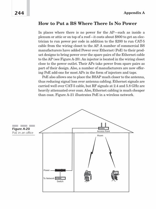
How to Put a BS Where There Is No Power
In places where there is no power for the AP—such as inside aplenum or attic or on top of a roof—it costs about $800 to get an elec-trician to run power per code in addition to the $200 to run CAT-5cable from the wiring closet to the AP. A number of commercial BSmanufacturers have added Power over Ethernet (PoE) to their prod-uct designs to bring power over the spare pairs of the Ethernet cableto the AP (see Figure A-20). An injector is located in the wiring closetclose to the power outlet. Their APs take power from spare pairs aspart of their design. Also, a number of manufacturers are now offer-ing PoE add-ons for most APs in the form of injectors and taps.
PoE also allows one to place the BSAP much closer to the antenna,thus reducing signal loss over antenna cabling. Ethernet signals arecarried well over CAT-5 cable, but RF signals at 2.4 and 5.8 GHz areheavily attenuated over coax.Also, Ethernet cabling is much cheaperthan coax. Figure A-21 illustrates PoE in a wireless network.
Appendix A244
Power
SwitchTo Network
Room
Access PointFigure A-20PoE in an office
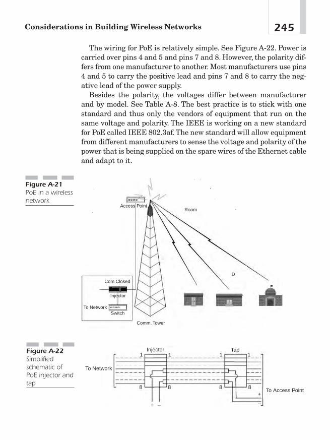
245Considerations in Building Wireless Networks
Access Point
Com Closed
Injector
SwitchTo Network
Comm. Tower
D
Room
Figure A-21PoE in a wirelessnetwork
The wiring for PoE is relatively simple. See Figure A-22. Power iscarried over pins 4 and 5 and pins 7 and 8. However, the polarity dif-fers from one manufacturer to another. Most manufacturers use pins4 and 5 to carry the positive lead and pins 7 and 8 to carry the neg-ative lead of the power supply.
Besides the polarity, the voltages differ between manufacturerand by model. See Table A-8. The best practice is to stick with onestandard and thus only the vendors of equipment that run on thesame voltage and polarity. The IEEE is working on a new standardfor PoE called IEEE 802.3af. The new standard will allow equipmentfrom different manufacturers to sense the voltage and polarity of thepower that is being supplied on the spare wires of the Ethernet cableand adapt to it.
To Network
Injector
+
+
– –
1 1 1 1
8 8 8 8
Tap
To Access Point
Figure A-22Simplifiedschematic ofPoE injector andtap

How to Overcome Line-of-Sight Limitations
The biggest challenge to providing Internet over WMAN is line ofsight. So one of the keys to success as a Wireless ISP is to get siteswith lots of height above average terrain or get hilltop locations andlink those together using long-haul connections. From the key loca-tions, it’s possible to bring the signal to neighboring sites within athousand feet or so. It’s then possible to extend service from one loca-tion to a few more, as long as redundant paths are brought in tocover the new location. Perfect line of sight is not necessary when thesignal is strong enough. Figure A-23 illustrates overcoming line-of-sight issues.
Appendix A246
Optional Link forRedundancy
Figure A-23Tiered networkto overcomeline-of-sightlimitation
Pins 4 and 5 � and Pins 7 and 8 � Pins 4 and 5 � and Pins 7 and 8 �
5V
12V Intel, 3 Com, Symbol, Orinoco
24V Intel, 3 Com, Symbol, Orinoco
48V Cisco
Table A-8
InjectedVoltages andPolarities byManufacturer
16-bit connection identifiers (CIDs), MediumAccess Control (MAC) layer, 31
2.4 GHz band, nonoverlapping channels, 2285 GHz channels, 228—230, 22956-bit DES, 6, 98802.11 (Wi-Fi), Medium Access Control (MAC)
layer, 14802.11 protocol WiMAX, 14, 208, 215802.11a, U-NII bands, 83, 216802.11b wireless protocol, 216802.11g wireless protocol, 217802.16 (WiMAX) standard
adaptive modulation support, 54—55business case, 163—196development history, 2—3disruptive technology, 197—204dynamic frequency selection (DFS), 93—94FCC Part 15, Section 247 relationship, 143FCC Part 15, Section 407 relationship,
143—144forward error correction (FEC), 56—57frequency spread, 83Internet Protocol Television (IPTV), 138—138licensed/unlicensed spectrum issues, 140—142Medium Access Control (MAC) layer, 15,
29—39OFDM, 14, 64—67physical layers, 15power limits, 142—143QoS supported service types, 61Quadrature Amplitude Modulation (QAM),
14, 63—66Quadrature Phase Shift Keying (QPSK), 14,
63—66quality of service (QoS), 6, 54—75security, 95—104security sublayer, 96—100voice over IP (VoIP), 105—129
A
access, Public Switched Telephone Network(PSTN) methods, 5, 106
adaptive antenna (AA)adaptive antenna system (AAS), 92interference mitigation, 91—93non-AAS cell, 91
adaptive antenna system (AAS)beam forming, 90interference mitigation, 89—91Spatial Division Multiple Access (SDMA),
18, 89WiMAX physical layer development, 18
adaptive modulation, quality of service (QoS)issue, 54—55
amateur radio, regulatory issues, 149AmberWaves WISP, voice over IP (VoIP) case
study, 127—128amplifier power, calculating, 219—220antenna specifications, 237—243antennas
adaptive antenna (AA), 91—93adaptive antenna system (AAS), 18, 89—91diversity, 242—243equivocally isotropic radiated power
(EIRP), 143FCC preemption of local law, 150—151frequency diversity, 243height limitations, 151interference temperature, 79—80, 154—155multipath cancellation, 242polarization, 243regulatory issues, 143, 144, 150—151spatial diversity, 243temporal diversity, 242weatherproofing, 243
INDEX
Copyright © 2005 by The McGraw-Hill Companies, Inc. Click here for terms of use.

application server, softswitch component,116—117
asynchronous transfer mode (ATM), PublicSwitched Telephone Network (PSTN), 4
attenuation, link budget, 222—223authentication
subscriber station (SS), 44, 45X.509 encryption, 98
authorizationprivacy key management (PKM) protocol,
100—102service flows, 71—75
Authorization Information messages,elements, 101
Authorization Module, service flows, 71—75Authorization Reply message, elements, 101Authorization Request messages, elements, 101automatic repeat request (ARQ), Medium
Access Control (MAC) layer, 37—38
B
backhaul (fiber optic) industrybusiness case, 166WiMAX bypass concerns, 10—11
bandwidthallocation polling methods, 59costs, 233Internet Protocol Television (IPTV)
requirements, 136Media Access Control (MAC), dynamic
allocation, 30request/grant mechanisms, 57—62
base station antennasbipole, 235directional, 235omnidirectional, 233—234parabolic, 236—237vertical, 234Yagi, 235
base station (BS)Authorization Reply message, 101
capital expense (CAPEX) item, 173—174coverage area, 85Key Reply message, 102placing without power, 244—245privacy key management (PKM) protocol,
97—99radio link control (RLC), 46—48ranging response (RNG-RSP), 43security associations (SAs), 99—100service flow initiation, 74service flows, 45—46TEK exchange, 102uplink (UL) and downlink (DL) structure, 17
basic connection, subscriber station (SS), 32beam forming, adaptive antenna system (AAS),
18, 90Best Effort (BE) Services, Medium Access
Control (MAC) layer, 33best-effort service, bandwidth allocation, 61—62bipole antenna, 235bit error rate (BER), 208Black Ravens, 94blocking performance, receiver interference, 82Blown to Bits (Phillip Evans and Thomas
Wurster), 201Boltzman’s Constant, 79bonding, antennas, 239—240broadband, business case, 186—194broadcast auxiliary, regulatory issues, 149BS Edge, capital expense (CAPEX) item,
173—174building materials, attenuation, 224building wireless networks, 206—246burst profiles
Downlink Interval Usage Code (DIUC), 46—48Medium Access Control (MAC) layer, 33—34Uplink Interval Usage Code (UIUC), 46—48
Bus topology, 206business case
cable TV replacement, 180—181capital expense (CAPEX) items, 172—176cell phone replacement, 179—180cellular backhaul, 166—167computer sales, 189—190
Index248
demographics, 167—169enterprise networks, 182—194frequency band alternatives, 170—172future markets, 179—181immediate markets, 164—166license-exempt spectrum, 170—171local loop bypass, 164—165operating expense (OPEX) items, 176—178private networks, 167public networks, 184—186public safety services, 167residential markets, 165, 185—186scenarios, 172secondary markets, 166—167services, 168—170small/medium business, 165SOHO high-speed Internet access, 165,
185—186Wi-Fi hot spot backhaul, 166WiMAX and VoIP, 191—194wireless broadband applications, 186—194wireless office, 182—184
C
cable TVreplacement business case, 180—181TV over Internet Protocol (TvoIP), 9, 10versus Internet Protocol Television (IPTV),
132—134WiMAX and IPTV bypass, 174WiMAX cost comparison, 181
capital expense (CAPEX) items, business caseelement, 172—176
CBC IV, data encryption, 103—104cell phone companies, voice over Internet
Protocol (VoIP) bypass, 9, 10cell phone replacement, business case, 179—180cellular backhaul, business case, 166—167central offices (COs), Class 5 switches, 4Cflix, video on demand development history, 137Christensen, Clayton (The Innovator’s
Dilemma), 9
circuit switched transport, Public SwitchedTelephone Network (PSTN), 4
Class 4 switches, Public Switched TelephoneNetwork (PSTN), 4
Class 5 switches, Public Switched TelephoneNetwork (PSTN), 4
Classifier Rule Table, 50coax attenuation losses, 223coax losses, link budget, 222co-channel (CoCh), 79—82), 80, 85—86Code of Federal Regulations, Title 47, radio
spectrum regulations, 142codecs, voice over IP (VoIP), 109, 122—123colinear antenna, 234common part sublayer, Medium Access Control
(MAC) layer, 35—36Communications Assistance to Law
Enforcement Agencies (CALEA), 125—126compression, Internet Protocol Television
(IPTV) requirements, 136compression rate, voice over IP (VoIP)
detractor, 122computer sales, business case, 189—190connector losses, link budget, 222connectors, requirements for antennas, 238—239content, Internet Protocol Television (IPTV)
component, 134contention procedures, Medium Access Control
(MAC) layer, 33—34convenience, WiMAX advantage, 200—201core network, capital expense (CAPEX) item,
173—174Crandall, Robert, 8
D
Data Encryption Standard (DES), encryptionalgorithm, 103—104
Data-Over-Cable Service InterfaceSpecification (DOCSIS), 49
decibels, Fresnel zone, 219—220delay (latency), voice over IP (VoIP) detractor,
120—121
249Index
demographics, business case element, 167—169deployment, WiMAX cost advantage, 199design
802.11, 215802.11a, 216802.11b, 216802.11g, 217environment, 207frequency band, 209—215link budget, 209link type, 207multipath fading tolerance, 209network topology, 206—207throughput, range and BER, 208
diffraction losses, link budget, 222digital video recorder (DVR), Internet Protocol
Television (IPTV), 138directional antennabase station, 235
coverage, 235regulatory issues, 143
DirecTiVO, personal video recorder (PVR)support, 138
disruptive technologiesdefined, 198WiMAX threat, 9—11
DL subframe, WirelessMan-SC 10-66 GHzvariant, 25—26
downlink (DL)FDD system, 17radio link control, 46—48WirelessMan-SC 10-66 GHz variant, 23—25
Downlink Interval Usage Code (DIUC), burstprofiles, 46—48
dropped packets, voice over IP (VoIP) detractor, 121
dynamic frequency selection (DFS),interference mitigation, 93—94
Dynamic Security Associations, 100
E
economic pull-through, wireless broadband, 188efficiency, WiMAX advantage, 200
emergency services (E911), voice over IP (VoIP), 125
encapsulation protocol, security component, 96encoding, Internet Protocol Television (IPTV)
component, 134—135encryption
CBC IV, 103—104cryptographic methods, 102—104DES in CBC mode, 103—104packet data encryption, 97X.509, 6
enterprise networks, business case, 182environment, design consideration, 207equipment, capital expense (CAPEX) item, 174—175equipment identifiers, 48-BIT MAC address,
31—32equipment selection
specifications, 231—232WAN/MAN connection, 232—244
equivocally isotropic radiated power (EIRP)antenna, regulatory issues, 143
error correction, orthogonal frequency divisionmultiplexing (OFDM), 66—67
Ethernet, wireless forms, 15Evans, Phillip (Blown to Bits), 201exurban areas, demographic element, 167—169
F
FAA, tower registration, 151fade margin, interference cause, 86Fast Fourier Transform (FFT), OFDM
development history, 16, 62Federal Communications Commission (FCC)
broadband/spectrum policy comments,159—161
Code of Federal Regulations, Title 47, 142frequency bands, 210—212Interference Protection Working Group, 154Part 15, 8Part 15, Section 247, WiMAX relationship,
143, 210Part 15, Section 407, WiMAX relationship,
143—144, 210
Index250
Part 15.3(m), regulatory issues, 145Part 15.5(b), regulatory issues, 145Part 15.5(c), regulatory issues, 146Part 17.7(a), 151Part 18, regulatory issues, 147—148Part 25, regulatory issues, 148—149Part 74, regulatory issues, 149Part 90, regulatory issues, 149Part 97, regulatory issues, 149Part 101, regulatory issues, 150preemption of local law, 150—151spectrum policy, 152—159Radio Act of 1927, 6, 78spectrum management, 142Spectrum Policy Task Force, 78—79
Federal Radio Commission, Radio Act of 1927, 78federal usage (NTIA/TRAC) band, regulatory
issues, 150fiber optic (backhaul) industry
business case, 166WiMAX bypass concerns, 10—11
fiberglass, attenuation, 223—224fixed microwave services, regulatory issues, 150fog, attenuation, 222footprint, WiMAX cost advantage, 200forward error correction (FEC), quality of
service (QoS) mechanism, 56—57Four-to-One reuse pattern, 230fragmentation subheader, Medium Access
Control (MAC) layer, 35frequency band alternatives, business case,
170—172frequency bands
FCC regulations, 210—212Industrial, Scientific, and Medical (ISM)
Band, 209power limits, 211U-NII band, 210
frequency diversity, antennas, 243frequency division duplex (FDD)
quality of service (QoS) mechanism, 55—56WiMAX physical layer development, 14, 17
frequency planmaking, 228—230reuse, 228—230
Fresnel zonedecibels/signal strength, 219first and second, 218planning, 217—220
future markets, business case element, 179—181
G
G.711, compression algorithm, 109G.723, compression algorithm, 109G.728, compression algorithm, 109G.729, compression algorithm, 109gain, antenna, 237gatekeepers, softswitch development
history, 114government command/control,
problem/solution, 157—158GPC class, bandwidth request/grant
mechanism, 57—62GPSS class, bandwidth request/grant
mechanism, 57—62grant management subheader, Medium Access
Control (MAC) layer, 35grant services, Medium Access Control (MAC)
layer, 32, 34grounding, antennas, 239—240guard intervals, intersymbol interference
(ISI), 88
H
H.225.0 protocol, voice over IP (VoIP), 111H.245 protocol, voice over IP (VoIP), 111H.323 protocolsoftswitch, 114voice over IP (VoIP) signaling, 109—111half-duplex FDD (H-FDD), uplink (UL) and
downlink (DL) structure, 17half-power beam width, antennas, 237—238harmful interference, regulatory issues,
145—150
251Index

household telecommunications, cost comparison, 186
hubs (offices), Public Switched TelephoneNetwork (PSTN) switching element, 4
Hypertext Transfer Protocol (HTTP), SIPsimilarities, 112
I
immediate markets, business case, 164—166industrial, scientific, and medical (ISM) band
channels, 83, 84regulatory issues, 147—148
injected voltages/polarities by manufacturer, 246The Innovator’s Dilemma (Clayton
Christensen), 9Institute of Electrical and Electronic Engineers
(IEEE) standard authority, 2inter exchange carriers (IXCs), asynchronous
transfer mode (ATM), 4Interdepartmental Radio Advisory Committee
(IRAC), spectrum regulation, 142interference
adaptive antenna (AA), 91—93adaptive antenna system (AAS), 89—91blocking performance, 82Boltzman’s Constant, 79channel changing, 83—84co-channel (CoCh), 79—82, 85—86counter measures, 82—88distance considerations, 84—85dynamic frequency selection (DFS), 93—94fade margin, 86FCC spectrum policy, 153—155harmful, 145—150industrial, scientific, and medical (ISM)
band, 83, 84Interference Protection Working Group,
78—79interference temperature, 79—80, 154—155intersymbol interference (ISI), 87—88link budget concept, 84—85multipath distortion, 86
multipath reflections, 87out-of-channel, 79—81power level issues, 85regulatory issues, 144—150spectral sidelobes, 81unlicensed national information
infrastructure (U-NII), 83wireless system assumptions, 78
Interference Protection Working Group, 154interference temperature, 80
defined, 79regulatory issues, 154—155
interleaving, orthogonal frequency divisionmultiplexing (OFDM), 66—67
International Telecommunications Union (ITU-T), H.323 protocol, 110—111
Internet Protocol Television (IPTV)bandwidth requirements, 136compression requirements, 136content/programming, 134encoding, 134—135infrastructure, 136IP Streaming, 135local encoding/streaming, 135personal video recorder, (PVR) 138satellite transport, 135system architecture, 135versus cable/satellite, 132—134versus legacy TV, 136—137versus video on demand, 137—138
intersymbol interference (ISI), 87guard intervals, 88RF propagation, 241—242
IP streaming, Internet Protocol Television(IPTV) component, 135
J
Jackson, Charles, 8jitter, voice over IP (VoIP) detractor, 122Jumpstart Broadband Bill, 151
Index252
K
Key Reply messages, TEK state machines, 102Key Request messages, TEK state machines, 102
L
land mobile radio services, regulatory issues, 149latency (delay), voice over IP (VoIP) detractor,
120—121Lessig, Larry, 78licensed spectrum, business case, 170—171lightning protection, antennas, 239—240line-of-sight limitations, overcoming, 246line-of-sight versus non-line-of-sight, 208link budget
calculating, 220—227design, 209
link margin, link budget, 221—222local encoding/streaming, Internet Protocol
Television (IPTV) component, 135local exchange carriers (LECs), asynchronous
transfer mode (ATM), 4local loop bypass, business case, 164—165local offices, Class 5 switches, 4local television transmission service (LTTS),
regulatory issues, 150
M
mean opinion score (MOS), voice qualitymeasurement method, 118—119
Media Gateway Controllers (MGC), softswitchdevelopment, 114
media gateway, softswitch component, 116Medium Access Control (MAC) layer
16-bit connection identifiers (CIDs), 31802.11, 14automatic repeat request (ARQ), 37—38Best Effort (BE) Services, 33burst profiles, 33—34
common part sublayer, 35—36connection-oriented, 31convergence sublayers, 34—39dynamic bandwidth allocation, 30GPC class, 57—62GPSS class, 57—62management connections, 32Non-Real-Time Polling Services (nrtPS), 33packing/fragmentation process, 37physical layer support, 38point-to-multipoint distribution, 31protocol data unit (PDU), 31
privacy sublayer, 97quality of service (QoS), 32—34Real-Time Polling Services (rtPS), 33scheduling mechanisms, 32—34SDU/PDU fragmentation/packing, 36self-correcting protocol, 58service classes, 32—34subheaders, 35TC sublayer, 39transmission convergence (TC) layer, 39transmission convergence sublayer PDU, 35Unsolicited Grant Services (UGS), 32uplink subframe, 38WiMAX, 15
Memorandum of Final Judgement of 1984(MFJ of 1984), PSTN reforms, 5
Mesh topology, 206—207MGCP protocol, softswitch, 114mobile satellite service (MSS), U-NII bands, 210MovieLink, video on demand development
history, 137MPEG-2 transport, Internet Protocol Television
(IPTV) encoding, 134—135multipath distortion, interference cause, 86multipath fading tolerance, design
considerations, 209multipath interference, RF propagation, 240multiple wave patterns in unobstructed
paths, 240
253Index
N
National Telecommunications and InformationAdministration (NTIA), 142
Netrix Corporation, voice over IP (VoIP)development history, 108
network infrastructure, capital expense(CAPEX) item, 175
network topology, design considerations,206—207
non line-of-sight (NLOS)positioning, multipath fading, 209WiMAX range, 2—3nonoverlapping channels, 2.4 GHz band, 228Non-Real-Time Polling Services (nrtPS)
bandwidth allocation, 61—62Medium Access Control (MAC) layer, 33
nonstandard connectors, antennas, 238—239
O
object models, quality of service (QoS), 70—71offices (hubs), Public Switched Telephone
Network (PSTN) switching element, 4omnidirectional antennas, coverage area, 234Open Systems Interconnection (OSI) Reference
Models, 14, 15operating expense (OPEX) items, business case
element, 176—178operations, administration, maintenance, and
provisioning (OAM&P), 199orthogonal frequency division multiplexing
(OFDM)development history, 16error correction, 66—67Fast Fourier Transform (FFT), 16, 62—63interference, 86—87intersymbol interference (ISI), 88multiplexing, 64—67physical layer (PHY) element, 14QoS mechanism, 55—56receiver, 65
throughput, 16transmitter, 65
outdoor site survey, 227—228out-of-channel, 80out-of-channel, interference classification,
79—81
P
packet data encryption, security component, 97packing subheader, Medium Access Control
(MAC) layer, 35panel antenna, 236parabolic antenna, 236—237, 237Part 15, wireless service regulations, 8path loss, link budget, 221perceptual speech quality measurement
(PSOM), voice quality, 119personal video recorder (PVR), Internet
Protocol Television (IPTV), 138physical layer (PHY)
802.11, 14legacy technologies, 16—18privacy sublayer, 97WiMAX, 15WiMAX variants, 18—27WirelessHUMAN, 22WirelessMAN-OFDM, 19—21WirelessMAN-OFDMA, 21—22WirelessMan-SC 10-66 GHz, 22—26WirelessMan-SCa 2-11 GHz, 26—27
planningfrequency allocation, 230—231Fresnel zone, 217—220link budget, 220—227making frequency plans, 228—230site survey, 227—228
point-to-multipointdistribution, 31links, 207links, 208power limits, 210, 213
Index254
regulatory issues, 143, 144WiMAX distribution, 2—3
point-to-pointlinks, 207links, 208power limits, 212, 214, 215regulatory issues, 143, 144WiMAX range, 2
polarization, antennas, 243polling services, Medium Access Control (MAC)
layer, 32—33polls, bandwidth allocation methods, 59—60Powell, Michael, 125—126, 152, 159—161power limits, regulatory issues, 142—143Power over Ethernet (PoE)
base station power, 244—245office placement, 244wireless network, 245
primary management connection, subscriberstation (SS), 32
Primary Security Associations, subscriberstation (SS), 100
privacy key management (PKM) protocol AK exchange, 100—102security component, 97—99, 100—102SS authorization, 100—102
private networks, business case, 167programming, Internet Protocol Television
(IPTV) component, 134protocol data unit (PDU), Medium Access
Control (MAC) layer, 31Provisioned Service Flow Table, 50proxy server, voice over IP (VoIP), 113public interest, FCC policy, 158—159public networks, business case, 184—186public safety services, business case, 167Public Switched Telephone Network (PSTN)
access components, 5architecture, 106—107asynchronous transfer mode (ATM), 4broadband wireless alternative, 7circuit switched transport, 4components, 3hubs (offices), 4
infrastructure barriers, 2local loop bypass, 165Memorandum of Final Judgement of 1984
(MFJ of 1984), 5softswitch bypass technology, 5star network, 4substitution technologies, 5switching components, 3—4Telecommunications Act of 1996, 5, 106transport components, 4TV over Internet Protocol (VoIP) bypass, 9, 10versus Internet Protocol Television (IPTV),
132—134voice over Internet Protocol (VoIP) bypass,
9, 10VoIP delivery alternative, 166WiMAX and VoIP bypass, 179WiMAX cost comparison, 181wireless network objections, 6—8Telecommunications Act of 1996, 106
Q
Quadrature Amplitude Modulation (QAM)versus Quadrature Phase Shift Keying
(QPSK), 63—66WiMAX physical layer development, 14
quality of service (QoS)Authorization Module, 71—75bandwidth allocation polling methods, 59bandwidth requests/grants, 57—62DSA message flow, 73, 74dynamic bandwidth allocation, 54dynamic service flow, 75error correction, 66—67Fast Fourier Transform (FFT), 62—63forward error correction (FEC), 56—57GPC class, 57—62GPSS class, 57—62interleaving, 66—67Medium Access Control (MAC) layer, 32—34modulation schemes, 63, 64
255Index

quality of service (Continued)object model, 70—71operational theory, 67—68orthogonal frequency division multiplexing,
64—66Quadrature Phase Shift Keying (QPSK)
versus Quadrature AmplitudeModulation (QAM), 63—66
service classes, 71service flow ID (SFID), 72—73service flow management messages, 74—75service flows, 68—69, 71—75supported service types, 61WiMAX concerns, 6
R
Radio Act of 1927, wireless regulatoryframework, 6, 78
radio link control (RLC), 47connection stability, 46—48
rain, attenuation, 222ranging request (RNG-REQ), subscriber station
(SS) negotiations, 43ranging response (RNG-RSP), base station (BS)
negotiations, 43Real-Time Polling Services (rtPS)
bandwidth allocation, 60—61Medium Access Control (MAC) layer, 33
receive antenna gain, link budget, 221receivers, blocking performance, 82receiving antennas, interference temperature,
79—80, 154—155redirect server, voice over IP (VoIP), 113regional Bell operating companies (RBOCs),
line loss reasons, 128—129registrars, voice over IP (VoIP), 113registration, subscriber station (SS), 44, 45regulatory issues
amateur radio, 149antennas/towers, 150—151broadcast auxiliary, 149
FAA/FCC tower registration, 151FCC Part 15, Section 247, 143, 210FCC Part 15, Section 407, 143—144, 210FCC Part 15.5(b), 145FCC Part 15.3(m), 145FCC Part 15.5(c), 146FCC Part 17.7(a), 151FCC Part 18, 147—148FCC Part 25, 148—149FCC Part 74, 149FCC Part 90, 149FCC Part 97, 149FCC Part 101, 150federal usage (NTIA/TRAC) band, 150fixed microwave services, 150industrial, scientific, and medical (ISM),
147—148interference, 144—150Jumpstart Broadband Bill, 151land mobile radio services, 149licensed/unlicensed spectrum, 140—142local television transmission service
(LTTS), 150point-to-multipoint, 143, 144point-to-point, 143, 144power limits, 142—143satellite communications, 148—149spectrum allocation for U-NII and
Co-users, 146spectrum policy, 152—159U-NII band, 144, 147United States ISM Channel Allocations, 147unlicensed frequencies, 151—152unlicensed spectra/associated power data, 148
Republic Telcom, voice over IP (VoIP)development history, 107—108
residential marketsbusiness case, 165, 185—186operating expense (OPEX) items, 176—178
RF propagation, antennas, 240—242Ring topology, 206
Index256
S
Satellite Broadcasting and CommunicationsAssociation (SBCA), 150—151
satellite communications, regulatory issues,148—149
satellite transport, Internet Protocol Television(IPTV) component, 135
satellite TVTV over Internet Protocol (TvoIP), 9, 10versus Internet Protocol Television (IPTV),
132—134scheduling mechanisms, Medium Access
Control (MAC) layer, 32—34scheduling services, WiMAX, 48—49secondary markets, business case, 166—167security associations (SAs), types, 99—100security
56-bit DES, 6, 98Authorization Information message, 101Authorization Reply message, 101Authorization Request message, 101CBC IV, 103—104cryptographic methods, 102—104DES in CBC mode data encryption, 103—104encapsulation protocol, 96Key Reply messages, 102Key Request messages, 102packet data encryption, 97privacy key management (PKM) protocol,
97—99, 100—102security associations (SAs), 99—100security sublayer, 96—100subscriber station (SS)
authentication/registration, 44, 45TEK exchange, 102voice over IP (VoIP) objections, 124—125X.509 encryption, 6, 44, 98
Service Class Table, 50service classes
Medium Access Control (MAC) layer, 32—34quality of service (QoS), 71
service flow ID (SFID), quality of service (QoS)element, 72—73
service flow management messages, 75service flows
BS-initiated, 74elements, 69management messages, 74—75SS-initiated, 73—74WiMAX connection setup, 45—46
services, business case element, 168—170Session Initiation Protocol (SIP)
client/server network architecture, 112—113Hypertext Transfer Protocol (HTTP)
similarities, 112uniform resource locators (URLs), 112voice over IP (VoIP), 109, 111—113
Seven-to-One reuse pattern with spare, 231signal strength, Fresnel zone, 219—220signaling gateway, softswitch component,
115—116signaling protocols
softswitch, 114voice over IP (VoIP), 109—113voice over IP (VoIP), 111
Signaling System 7 (SS7), softswitch, 114Simple Mail Transfer Protocol (SMTP), SIP
development, 112single carrier (SC), WiMAX variants, 22—27site survey, planning, 227small/medium business, business case, 165softswitch
application server, 116—117call controls, 114component relationships, 116gatekeepers, 114media gateway, 116Media Gateway Controllers (MGC), 113—115peer-to-peer signaling, 114PSTN alternatives, 107PSTN switch bypass technology, 5service logic functions, 114signaling gateway, 115—116signaling protocols, 114
257Index

softswitch-to-gateway signaling, 114usage statistics, 115
SOHO high-speed Internet access, businesscase, 165, 185—186
spatial diversity, antennas, 243Spatial Division Multiple Access (SDMA),
beam-forming techniques, 18specifications, equipment selection, 231—232spectrum
business case element, 170—171FCC policy, 152—159licensed/unlicensed operation issues, 140—142
Spectrum Policy Task Force, InterferenceProtection Working Group, 78—79, 154
spectrum scarcity, FCC policy, 155—157speech codecs, voice over IP (VoIP), 123—124speech-processing software, voice over IP
(VoIP) enhancement, 123—124star networks, Public Switched Telephone
Network (PSTN), 4Star topology, 206Starz Ticket, video on demand development
history, 137Static Security Associations, base station
(BS), 100subscriber station (SS)
48-bit MAC address, 31—32authentication, 44, 45Authentication Information message, 101Authorization Request message elements, 101bandwidth allocation polling methods, 59—60GPC class, 57—62GPSS class, 57—62initial ranging/negotiations, 42—43IP connectivity process, 44—45management connections, 32privacy key management (PKM), 97—102ranging request (RNG-REQ), 43registration, 44, 45security associations (SAs), 99—100service flow initiation, 73—74service flows, 45—46TEK exchange, 102uplink (UL) and downlink (DL) structure, 17
switching, Public Switched Telephone Network(PSTN), 3—4, 106
system architecture, Internet ProtocolTelevision (IPTV) component, 135
T
tandem offices, Class 4 switches, 4TEK state machines, Key Request messages, 102Telecommunications Act of 1996
PSTN reforms, 5PSTN switching access, 107
telecommunications industrydeconstruction issues, 201—203disruptive technologies, 9—11
temporal diversity, antennas, 242theory of operation object model, 70three-to-one reuse pattern 229throughput
OFDM versus non-OFDM, 16WiMAX capability, 2
tiered network, 246time division duplex (TDD)
quality of service (QoS) mechanism, 55—56subframe, 56WiMAX, 14, 17
time-shifting, personal video recorder (PVR), 138towers
FCC preemption of local law, 150—151height limitations, 151regulatory issues, 150—151transmission convergence (TC) layer,
Medium Access Control (MAC) layer, 39
transmission convergence sublayer PDU,Medium Access Control (MAC), 35
transmit power, link budget, 220Transmitter Power Output (TPO), regulatory
issues, 143, 144transmitters, spectral sidelobes, 81transport connections, subscriber station
(SS), 32transport protocols, voice over IP (VoIP), 111transport, Public Switched Telephone Network
(PSTN), 4, 106Tree topology, 206
Index258
trees, attenuation, 223TV over Internet Protocol (TvoIP), PSTN
bypass method, 9, 10twisted pair wire, Public Switched Telephone
Network (PSTN) handsets, 5
U
UA server, voice over IP (VoIP), 113uniform resource locators (URLs), SIP
URLs, 112U-NII bandchannels, 83
frequency allocation, 210regulatory issues, 144, 146, 147unlicensed frequencies, regulatory issues,
151—152unlicensed national information infrastructure
(U-NII) band, channels, 83unlicensed spectrum, business case, 170—171unlicensed transmitters, antenna connectors,
238—239Unsolicited Grant Services (UGS)
bandwidth allocation polling, 59—61Medium Access Control (MAC) layer, 32
uplink (UL)FDD system, 17radio link control, 46—48scheduling services, 48—49WirelessMan-SC 10-66 GHz variant, 23
Uplink Interval Usage Code (UIUC), burstprofiles, 46—48
user agents (UAs), SIP architecture, 112—113
V
vertical antenna, 234video on demand, versus Internet Protocol
Television (IPTV), 137—138voice over Internet Protocol (VoIP)
AmberWaves WISP case study, 127—128architecture elements, 126—128
CALEA, 125—126codecs, 109, 122—123compression rate, 122development history, 107—108dropped packets, 121emergency services (E911), 125enhanced speech-processing software,
123—124H.225.0 protocol, 111H.245 protocol, 111H.323 signaling protocol, 109—111jitter, 122latency (delay), 120—121linking offices, 128PSTN alternative, 127PSTN bypass method, 9, 10security objections, 124—125servers, 113Session Initiation Protocol (SIP), 109,
111—113signaling protocols, 109—113softswitch, 113—117speech codecs, 123—124switching functions, 113—117voice quality objections, 118—122workflow process, 108—109
voice quality, voice over IP (VoIP) objections,118—122
voice services, wireless local loop (WLL), 117
W
WAN connectionantennas, 233—237antennas-BS side, 233—237equipment selection, 232—244Internet choices, 232
weatherproofing, antennas, 243Wi-Fi hot spot backhaul, business case,
166—167, 167wired LAN, cost comparison, 183wireless broadband, business case, 186—194Wireless High Speed Unlicensed Metro Area
Network (WirelessHUMAN), 22
259Index
wireless Internet service provider (WISP), voiceaccommodation concerns, 6
wireless LAN, cost comparison, 183wireless local loop (WLL), voice services, 117wireless mesh topology, 207wireless metro area networks (WMANs)frequency bands, 210line-of-sight limitations, 246wireless networks
design, 206—217disruptive technology, 198equipment selection, 231—246
planning, 217—231wireless office, business case, 182—184, 184wireless protocols802.11 WiMAX, 14, 208, 215802.11a, 83, 216802.11b, 216802.11g, 217WirelessHUMAN, physical layer, 22WirelessMAN-OFDM, physical layer, 19—21WirelessMAN-OFDMA, physical layer, 21—22WirelessMan-SC 10-66 GHz, physical layer,
22—26WirelessMan-Single Carrier Access
(WirelessMan-SCa) 2-11 GHz, 26—27Worldwide Interoperability for Micro Wave
Access (WiMAX)56-bit DES encryption, 6802.16 standard, 2—3adaptive antenna system (AAS), 18, 89—91adaptive modulation support, 54—55backhaul bypass, 9business case, 163—196cell phone bypass, 9channel acquisition workflow, 43Classifier Rule Table, 49—50Data-Over-Cable Service Interface
Specification (DOCSIS), 49delivery capabilities, 2disruptive technology, 197—204dynamic frequency selection (DFS), 93—94dynamic service changes, 46FCC Part 15, Section 247 relationship, 143FCC Part 15, Section 407 relationship,
143—144
forward error correction (FEC), 56—57frequency division duplex (FDD), 14, 17, 55—56frequency spread, 83IEEE 802 standard offshoot, 15initial ranging transmissions, 42—43Internet Protocol Television (IPTV), 131—138IP connectivity process, 44—45licensed/unlicensed spectrum issues, 140—142Medium Access Control (MAC) layer, 15,
29—39non line-of-sight (NLOS) range, 2—3OFDM, 64—67, 86—87orthogonal frequency division multiplexing
(OFDM), 14, 16, 19—22, 55Part 15 regulations, 8physical layers, 15point-to-multipoint distribution, 2—3point-to-point range, 2power limits, 142—143Provisioned Service Flow Table, 49—50PSTN bypass, 9QoS supported service types, 61Quadrature Amplitude Modulation (QAM),
14, 63—66Quadrature Phase Shift Keying (QPSK), 14,
63—66quality of service (QoS), 6, 54—75quality-of-life enhancements, 8radio link control (RLC), 46—48), 47right-of-way concerns, 7scheduling services, 48—49security, 95—104security sublayer, 96—100Service Class Table, 49—50service flow provisioning, 50service flows, 45—46single carrier (SC) variants, 22—27subscriber station (SS)
authentication/registration, 44, 45throughput, 2time division duplex (TDD), 14, 17, 55—56voice over IP (VoIP), 105—129wireless alternative to PSTN, 7WirelessHUMAN variant, 22WirelessMAN-OFDM variant, 19—21WirelessMAN-OFDMA variant, 21—22
Index260
WirelessMan-SC 10-66 GHz variant, 22—26WirelessMAN-Single Carrier Access
(WirelessMAN-SCa) 2-11 GHz, 26—27X.509 encryption, 6
Wurster, Thomas (Blown to Bits), 201
X
X.509 encryption56-bit DES relationship, 98
authentication, 98subscriber station (SS) authentication, 44WiMAX security, 6
Y
Yagi antenna, 235Yagi antenna, in radome, 236
261Index


