20
MCplus SERIES A CONTROLLERS OWNER'S MANUAL 4,6, 8, 12, 18, 24, 30, 36 and 42 stations

MCplus SERIES ACONTROLLERS
OWNER'S MANUAL4,6, 8, 12, 18, 24, 30, 36 and 42 stations

Thank you for purchasing the Irri-Trol MCplus Series Controller.Listed below are some important features you should be aware ofbefore you begin programming. Details on how to implement thesefeatures are described on the following pages.
Programmable Watering Calendar from 1 to 16 days for appli-cation versatility
Sensor feature in program 4 for water conservation systems
Programmable Delay between stations to prevent pressure loss
Rechargeable Battery Back-up System to maintain “real time”and programmed information in the event of a power failure
Four independent programs for system versatility
Capability of operating up to 4 valves per station (MC-8plusthrough MC-42plus)
Water Budgeting for simple, single-entry increase or decrease ofwatering time per program
Total Watering Time display for quick review of scheduledwatering time per program
True Manual, Semi-automatic and/or Single Station TimedManual for versatile operation
Incomplete Program Alert to prevent errors in programming
Two-minute Test for easy system testing
RF Ready for upgrading to an Irri-Trol Remote Control System
Scrolling Program for information recall
Selectable Single Program option for winter/summer programs
Watering Times in seconds, minutes or hours
-- Selectable Loop option for continuous cycling of program
Single Entry All Stations On Time for ease of programming ( 30-,36-, and 42-station models)
These are just a few of the many features of the MCplus Series Con-trollers. Please review your manual before beginning programming.

TABLE OFCONTENTS
PAGE
Installation and Wiring Instructions.. . . . . . . . . . . . . . . . . . . . . 5
Basic Programming Instructions:
Set Time . . . . . . . . . . . . . . . . . . . .Set Today ...................Program Erase (P.E.) ..........DaysOnn . . . . . . . . . . . . . . . . . . . .Water Time . . . . . . . . . . . . . . . . . .Cycle Start. ..................Incomplete Programming ......
...........................
...........................
...........................
...........................
...........................
...........................
Manual Operation:
True Manual . . . . . . . . . . . . . . . . . . . . . . . . . . . . . . . . . . . . . . . . . . . . .Semi-automatic ..........................................Single Station Timed Manual ...............................Rain Off/2 Min. Test .......................................ManualOff . . . . . . . . . . . . . . . . . . . . . . . . . . . . . . . . . . . . . . . . . . . . . .
Display of Program:
Set Time ................................................Set Today ...............................................DaysOn/DaysOff . . . . . . . . . . . . . . . . . . . . . . . . . . . . . . . . . . . . . . . .Water Time/Total Watering Time/Scrolling . . . . . . . . . . . . . . . . . . .Cycle Start/Cycle End .....................................
Additional Features:
Automatic Safety Back-up Program (ASBP) ...................Programmable Watering Calendar ..........................Water Budgeting .........................................Programmable Delay Between Stations ......................Single Program Option ....................................Seconds Modee . . . . . . . . . . . . . . . . . . . . . . . . . . . . . . . . . . . . . . . . . . .Loop . . . . . . . . . . . . . . . . . . . . . . . . . . . . . . . . . . . . . . . . . . . . . . . . . . . .Sensor . . . . . . . . . . . . . . . . . . . . . . . . . . . . . . . . . . . . . . . . . . . . . . . . . .Remaining Water Time ....................................All Stations Watering Time .................................
Glossary ..............................................
1010101111
1111121212
13131314151515161616
17
2

MCplus SERIESCONTROLLERS1
2
7
8
9
10
11
12
13
14
15
16
17
18
19
20
21
22
23
24
25
110/24 volt transformer
Terminal Strip-for 24v, sensor, common, master valve and individualstation hook-ups
Set Time Key-to enter the current time of day and start the digital clock
Manual On/Off Key-for manual and semi-automatic operations
Station indication LEDs
PE/Calendar position-to select programs to be erased and/or to selectand display Watering Calendar
Rain Off / 2 Min. Test position-to select the Rain Off mode and/or theTwo-minute Test
Manual position-for true manual operation
Auto/Run position-to lock keyboard when not programming
Circuit Breaker-will reset when controller is overloaded to preventdamage to the controller; 24 VAC, 2.0 amps
Program positions 1 through 4-to select desired program
Number Keys 0 through 9-for programming applications
Digital Display-for viewing current time and programmed information
Enter Key-enters Water Time and Cycle Start functions
Water Time Key-for individual programming and/or recall of stationWatering Times
Cycle Start Key-for programming and/or recall of Cycle Start Times
Day Off Key-for scheduling and/or recalling non-watering days
Day On Key-for scheduling and/or recalling watering days
Clear Key-for clearing entries from the display
PM/% Key-for setting a time function in the p.m. period and/or forselecting the Water Budgeting feature
Set Today Key-for setting the current day of the week
RF Connector-for hook-up of an Irri-Trol Remote Valve Control
Option Switches-for selecting additional features (see page 13)
Rechargeable Battery Back-up Case and Connector
Lower Face Plate

4

INSTALLATIONINSTRUCTIONS
MOUNTING THECONTROLLER
The controller is in an outdoor, rain-tight, rust-resistant and dust-proof box.Nevertheless, controller MUST be installed away from direct sprinkler spray.It also should be placed in a shaded and dry location, if possible. DO NOTinstall in closed and humid environment, or in an area subjected to continualheavy condensation.
WALL MOUNT: For Wall Mounting, install controller vertically on flat, securesurface. Use the enclosed template to locate mounting screw holes. Followcomplete mounting instructions on template.
PEDESTAL: For free-standing installation on a pedestal, follow the instal-lation instructions in the pedestal box.
CAUTION: The controller should not be placed where it is exposed to atemperature exceeding 130° F.
ELECTRICAL 1. To begin, remove the lower panel by unfastening the screws located onHOOK-UP each side. Follow the wiring diagram shown in Figure 1, Strip wires
approximately l/4” (do not bend exposed end). Insert straight bare wirebetween plates of “sure grip” terminal. Tighten screw firmly. Follow allapplicable local electrical wiring codes,
Figure 1
COMMON
IMPORTANT: Use a separate (dedicated) valve common for each controller.
Note: Make certain that the 120 VAC 60Hz supply is attached to the blackand white wires of the transformer. The yellow and red wires go to the 24VAC input on the terminals of the controller.
CAUTION: NEVER short wires in order to identify a station or to verify powerfrom 24-volt side of transformer. This will result in damage to controllerand/or transformer.
2. A maximum of FOUR 4-watt solenoid valves may be connected to eachstation. Exception: MC-4plus & -6p/us, maximum of TWO 4-watt solenoids.A maximum of FOUR 4-watt solenoid valves may be programmed to operatesimultaneously.
3. In cases where a pump is to be controlled by the master valve output, DONOT drive the pump directly from the controller. The master station must beconnected to the coil of a 24 VAC relay, such as an Essex# 184-20105-101 Z(Irri-Trol part no. I 1001). The pump latch relay should be set up by anelectrician so that a switch closure will activate the latch relay coil, turning on
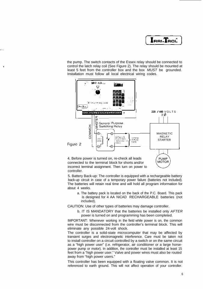
the pump. The switch contacts of the Essex relay should be connected tocontrol the latch relay coil (See Figure 2). The relay should be mounted atleast 5 feet from the controller box and the box MUST be grounded.Installation must follow all local electrical wiring codes.
220 / 440 V O L T S3@
MAGNETICRELAY
STARTER
4. Before power is turned on, re-check all leadsconnected to the terminal block for shorts and/orincorrect terminal assignment. Then turn on power tocontroller.5. Battery Back-up: The controller is equipped with a rechargeable batteryback-up circuit in case of a temporary power failure (batteries not included).The batteries will retain real time and will hold all program information forabout 4 weeks.
a. The battery pack is located on the back of the P.C. Board. This packis designed for 4 AA NICAD RECHARGEABLE batteries (notincluded).
CAUTION: Use of other types of batteries may damage controller.b. IT IS MANDATORY that the batteries be installed only AFTER
power is turned on and programming has been completed.
IMPORTANT: Whenever working in the field while power is on, the commonwire must be disconnected from the controller’s terminal block. This willeliminate any possible 24-volt shock.The controller is a solid-state microcomputer that may be affected bytransient surges and electromagnetic interference. Care must be taken notto install controller on a circuit controlled by a switch or on the same circuitas a “high power user” (i.e. refrigerator, air conditioner or a large horse-power pump or motor). In addition, the controller must be installed at least 15feet from a “high power user.” Valve and power wires must also be routedaway from “high power users.”This controller has been equipped with a floating valve common. It is notreferenced to earth ground. This will not affect operation of your controller.
6

CONTROLLERGROUNDINGTECHNIQUES
MCplus SERIESCONTROLLERS
For safety, transient protection and increased reliability, con-troller MUST be grounded.
Controller should be installed using a “three wire” 110 VACsupply with a verified third wire ground. Connect the greenground wire directly to the controller’s case. Do NOT wire 110volts directly to P.C. board terminals, the transformer suppliedwith controller MUST be used.Whenever possible, controller should be installed on its owndedicated circuit breaker. Under no circumstances should thecontroller be installed on the same line or within 15 feet of aheavy inductive load such as a pump, motor, air conditioner,refrigerator, etc.In areas where lightning is prevalent or the condition of thethird wire ground is questionable, a ground rod must beinstalled. Connect the grounding rod to the controller’s caseground using a #10 gauge or heavier stranded copper wire.The distance from the controller’s case to the earth groundshould be minimized. Additional 1 IO-volt transient protectionalso may be necessary in areas where power frequently isdisrupted.
6A

BASICPROGRAMMINGINSTRUCTIONSTo begin programming, Program Knob must be turned to program #1, #2, #3or #4. There are 5 required programming steps, which may be applied inany order. The sequence for pressing the keys in the following examples,however, must be followed exactly:
STEP #1 Set lime: Key in current time using numeral keys (If during p.m. period,press “PM/%” Key prior to ”Set Time” Key. The PM Indicator will show on theleft side of the display window). Then press “Set Time” Key.
EXAMPLEA: Time is 10:25 a.m., Press:
EXAMPLE B: Time is 3:23 p.m., Press:
Note: Midnight is 12:OO a.m.; Noon is 12:00 p.m.
STEP #2 Set Today: Key in the number corresponding to the current day of the week;then press “Set Today” Key.
EXAMPLE: Today is Wednesday, press:
BII’
At this point, the Program Erase may be activated to clear all programmedinformation:
a. Turn Knob to P.E./Calendar position.b. Press in the following key sequence: “1, 3, 7, 9.”c. Press “Enter” Key (display will show a flashing “PE” to indicate that
all programs have been erased).d. Return Program Knob to desired program.
IMPORTANT: The Set Time and Set Today functions automatically apply toall 4 programs and need only be entered once. The next 3 functions (DaysOn, Water Time and Cycle Start) apply ONLY to the program indicated by theProgram Knob and must be entered in each program that is intended tooperate automatically.

STEP #3 Set Days On: To program which days of the week the controller turns on,key in the number corresponding to a Day On and then press the “Day On”Key. Repeat for all selected watering days.
EXAMPLE:Selected watering days are Sunday, Tuesday and Thursday. Thecorresponding numbers for these days are:
Sunday=1 ; Tuesday=3; Thursday=5.To program, press:
To delete a programmed Day On, key in the number of that day, then pressthe ”Day Off” Key. When programming a Day On, display wiII show ”On” andthe number corresponding to the appropriate day of the week. To indicate aDay Off, display will show “Off” and the day number.
STEP #4 Set Water Time: Enter the watering duration for each station
To program Water Time:
a. Key in station number.b. Press “Water Time” Key.c. Key in watering duration.d. Press “Enter” Keye. Repeat for all stations to be entered in this program.
EXAMPLE #1: To set Station 8 to water for 25 minutes, press:
EXAMPLE #2: To set Station 16 to water for 1 hour and 20 minutes, press:
Programmed stations will turn on in sequence. Controller will skip anunprogrammed station. To delete a programmed station, enter “0” for WaterTime.Note: A flashing “P” on the display indicates previous Station Placement(see glossary) has been programmed. To change Station Placement, one ofthe original Water Times must be set to zero.To recall the Water Time entered for a station, key in the station number andthen press the “Water Time” Key.
8

STEP #5 Set Cycle Start: Enter the starting time for each watering cycle on thescheduled Days On.
To program Cycle Start:a. Press appropriate key to indicate number of cycle (in Programs #l
and #2, this can be “1, " “2” or “3” while in Programs #3 and #4, itcan be either “1 ” or “2”).
b. Press “Cycle Start” Key.c. Key in time of day that cycle is to start.d. If Cycle Start is during p.m. period, press the “PM/%” Key.e. Press “Enter” Key.f. Follow the same procedure for each additional Cycle Start.
Note: Use only one Cycle Start if the controller is to water once a day; CycleStart number is NOT related to station number.EXAMPLE: Controller is to initiate a watering cycle twice a day, on thescheduled Days On. First cycle is to start at 4:15 a.m., second cycle to start at9:45 p.m. Press:
Note: Only one watering cycle per program can be operating at any giventime; there must be at least a 1 -minute break between watering cycles toprevent the controller from skipping (ignoring) the second cycle.
To delete a Cycle Start, enter “0” as the starting time of the watering cycle.
To recall the programmed starting time of a watering cycle, key in number ofdesired Cycle Start and then press ‘Cycle Start” Key (Display will show[O:OO] if no Cycle Start was programmed).
Incomplete Program Alert: To check that programming has beencompleted:
Move Program Knob out of current program position. If programming isincomplete, controller will sound one long beep.IMPORTANT: This beep indicates that the program will NOT runautomatically.
To continue programming, turn Program Knob to next desired program andfollow Steps 3 through 5 above. Repeat for all desired programs.When programming has been completed, turn Program Knob to Auto Runposition. This will lock the keyboard, thus eliminating unintentional programentries. In Auto Run position, the current time will show on the display.

MANUALOPERATION
TRUE MANUALOPERATION
SEMI-AUTOMATIC
SINGLE STATIONTIMED MANUAL
Selected station will water until manually turned off.a. Turn Knob to Manual position.b. Key in station number.c. Press “Manual On/Off” Key.
To alert operator, controller will sound two quick beeps every 30 secondswhile a station is manually on.
To terminate True Manual Operation do ONE of the following:1. Press “Manual On/Off” Key; OR2. Select another station for manual operation; OR3. Move knob out of Manual position.
Note: FOR SAFETY A STATION THAT WAS TURNED ON MANUALLYWILL SHUT OFF AUTOMATICALLY AT MIDNIGHT
Allows manual activation of a watering cycle. Operation applies ONLY to theprogram designated by the Program Knob.
a. Turn Program Knob to desired program.b. Key in first station intended to turn o n .c. Press “Manual On/Off” Key. (Display will alternately flash station
number and Remaining Water Time.)
All stations programmed after the selected starting station will turn onautomatically in sequence.
Note: Selected starting station must have programmed Water Time in orderto turn on semi-automatically or controller will select the next programmedstation in sequence.
Manually turns on a station for the programmed Water Time withoutcontinuing to the next programmed station.
a. Turn Program Knob to desired program.b. Key in station number.c. Press “Water Time” Key.d. Press “Manual On/Off” Key. (Display will alternately flash station
number and Remaining Water Time.)e. Return Program Knob to Auto Run position.
EXAMPLE: For an additional watering of Station #1 without activating therest of the sequence in Program #2:
Turn Program Knob to Program #2. Then press:
Note: A station without programmed Water Time will NOT turn on.
10

RAIN OFF/2 MIN. a. Rain Off: Turns off all stations without affecting the program. It will notTEST POSITION allow automatic activation of any cycle(s).
Stations currently watering will turn off after a 2-second delay. While in RainOff position, display will read “OFF.” Taking Program Knob out of Rain Offposition will return controller to normal operation.
b. Two-minute Test: Tests all stations without affecting the program.
To begin the test with Station #1, press “Manual On/Off” Key. To begin withany other station, press that station number and then the “Manual On/Off”Key.IMPORTANT: If Program Knob remains in Rain Off /2 Min. Test position aftercompletion of Two-minute Test, controller will automatically assume the RainOff positiorNote: When moving Program Knob from Rain Off / 2 Min. Test position, thereis no need to reprogram.
MANUAL OFF Applies to Semi-automatic, Single Station Timed Manual and Two-minuteTest.To shut off a watering station: Press the “Manual On/Off” Key.
ONLY the station that is watering in the program indicated by the ProgramKnob will turn off. The cycle will be terminated whether it was initiatedsemi-automatically or automatically.
DISPLAY OFPROGRAMDisplaying information does not affect the program. To recall any of thefollowing functions, set Program Knob to Program #1, #2, #3 or #4. Repeatfor all desired programs.
SET TIME Press “Set Time” Key and display will show the current time. (When dial is inthe Auto Run position, display always will show the current time.)
SET TODAY Press “Set Today” Key. The number shown on the display will correspond tothe current day of the week.
Note: To change Set Time or Set Today, follow the directions given in BasicProgramming (p. 7). Newly programmed information replaces previouslyprogrammed information.

DAYS ON
DAYS OFF
WATER TIME
CYCLE START/CYCLE END
Press the “Day On” Key and display will scroll the days that are programmedas days on.
Press the “Day Off” Key and display will scroll the days that are programmedas days off.
a. To recall the Water Time programmed for a particular station, key inthe station number and then press the “Water Time” Key.
b. To recall Total Water Time, press “Clear” Key. Then press “WaterTime” Key. Display will indicated the Total Watering Time within theprogram.
Note: If the number that appears on the display is flashing, the Total WateringTime is greater than 100 hours. Add 100 to the flashing number for the trueTotal Watering Time.
c. Scrolling of Programmed Water Time: Lists consecutively thewatering time of each station beginning with the first one that isprogrammed.To activate:Press “Clear” Key. Then press “Water Time” Key once, and thedisplay will show the Total Watering Time for the selected program.Press “Water Time” Key again, and display will alternately flashstation number and watering time for each programmed station.
Note: Controller will not display stations with “0” Water Time.
To recall the starting time of a watering cycle, key in the number of thedesired Cycle Start; then press “Cycle Start” Key. To recall the ending time ofthe same watering cycle, press “Cycle Start” Key again.
EXAMPLE: In Program #2, the first watering cycle is programmed to beginat 6:00 a.m. The total watering time of all stations within the program is 14hours:
a. Turn knob to Program #2.b. Press numeral “1” Key.c. Press “Cycle Start” Key. Display will show the starting time of
6:00 a.m.d. Press ‘Cycle Start” Key again. Display will show the ending time
of 8:00 p.m. (PM Indicator will show in the left corner of the displaywindow.)
A flashing end time on the display indicates that the total Watering Time ofthe cycle exceeds 24 hours.
EXAMPLE: If the above cycle had a Total Watering Time of 27 hours insteadof 14 hours, the display would show a flashing end time (9:00 a.m.). Thiswould indicate that the cycle does not end during the same 24-hour periodin which it began, but rather during the following 24-hour period.
12

SELECTABLEAUTOMATIC SAFETY
BACK-UPPROGRAM (ASBP)
PROGRAMMABLEWATERING
CALENDAR
WATER BUDGETING
ADDITIONALFEATURESAt power-up, the ASBP is activated automatically in Program #l The ASBPwill be reactivated after every power failure if batteries fail or are not installed.
To deactivate the ASBP: Change Option Switch #3 to the on position (up).
The Watering Calendar may be programmed to range from 1 to 16 days. Thecalendar automatically is set by the factory to 7 days.
To change Programmable Watering Calendar:
a. Turn dial to P.E./Calendar position. Display will indicate currentlyprogrammed calendar length. Example: [PE:7] indicates a 7-dayweekly calendar.
b. Press numeral key(s) corresponding to desired calendar length(1-16).
c. Press “Enter” Key (the number on the display will flash to indicatethat the new calendar has been accepted).
Note: The number entered for Set Today and Days On cannot be greaterthan selected calendar length (see pp, 7 & 8).EXAMPLE: To water every other day, select an even number such as “2” forthe Calendar Length and choose 1 Day On. To water once every five days,select “5” for the Calendar Length and choose 1 Day On and 4 Days Off
Changes all Water Times within a program by 1% through 255%, with 100%being the current Water Time.The following scale shows Water Times (below the line) and the cor-responding percentages (above the line) for a station originally set to waterfor 30 minutes:
0% 10% 5 0 % 100% 150% 2 0 0 %
I 1 I I II I I I I
II
0 3min.=30xO.l 15 min.=30x0.5 3 0 min.=30xl .O 4 5 min.=30xl.5 6 0 min.=30x2.0
To program Water Budgeting:a. Turn Knob to desired program.b. Press the “PM/%” Key (display will show 100%).c. Key in new percent value.d. Press “Enter” Key.
Note: The entered percent value will flash on the display to indicated that ithas been accepted
(iixz-)
EXAMPLE A: To program controller to use only 2/3 of currently programmedWater Time for each station, multiply (2/3)x100 to get 67 (after rounding off).To decrease all of the Water Times in this program by that proportion, press:
If Station #I had been programmed to water for 30 minutes and Station #2had been programmed for 40 minutes, then Station #l would have beenchanged to (30x0.67)=20 minutes (decimals are rounded off), and Station#2 would have been changed to (40x0.67)=26 minutes.EXAMPLE 5: If the desired Water Time for at least one station is known, andall other stations are to be changed proportionately, the correct percentvalue to enter may be determined by:[(New Water Time) + (Current Water Time)]xlOO. If Station #4 is program-med to water for 25 minutes, and its new desired Water Time is 35 minutes,the correct percent value to enter is 35/25x100=140%.
Note: When Water Budgeting is used, the adjusted Water Times replace thepreviously programmed Water Times.
PROGRAMMABLEDELAY BETWEEN
STATIONS
There will be an interval between one station turning off and the next stationturning on in sequence. Delay may range from 1 second through 4 minutes.
To program Delay:a. Program Knob must be in a program position (important: option may
be accessed in any program but will apply to ALL programs).b. Press numeral “0” Key.c. Press “Water Time” Key.d. Press numeral key corresponding to the desired delay time.
Note:1, Master Valve will stay on during Delay.2. Controller automatically will enter Delay in seconds and minutes.3. Delay Time will be deducted from previous station’s Watering Time
EXAMPLE: To enter a Delay of 5 seconds, press:
To delete Delay, enter “0” as desired delay time
14

SINGLE PROGRAMOPTION
PROGRAM #4OPTIONS
Programs may be run separately according to Program Knob position. Thisoption allows for seasonal pre-programming.To use Single Program Option: Option Switch #2 must be in the on position(up). Option may be activated while controller is powered.
Cycle Start will operate on/yin the program indicated by the Program Knob.If the Program Knob is in the Auto Run, Manual or P.E./Calendar position, allprograms will operate concurrently.
The following options are available only in Program #4.
a. Seconds Mode: Changes all stations in Program #4 to seconds andminutes, with a maximum Water Time of 24 minutes instead of 24hours. If Loop option is being used, the last station in Program #4will remain in minutesand hours to allow for a programmable pausebetween loops.
To change to Seconds Mode: Option Switch #I must be in the on position(up). Option may be activated while controller is powered.
b. Loop Option: Repeats sequential watering of all stations in Program#4.
To program beginning time of Loop:1. Press numeral “2” Key.2. Press “Cycle Start” Key.3. Press numeral keys corresponding to desired beginning time of Loop.4. Press “Enter” Key.
To program ending time of Loop.1. Press numeral “0” Key.2. Press “Cycle Start” Key.3. Press numeral keys corresponding to desired end time of Loop4. Press “Enter” Key.
EXAMPLE: To program a Loop beginning at 8:00 a.m. and continuing until7:30 pm, press the following keys to set beginning time:
Now press the following keys to set the Loop’s ending time:
The Loop will finish at the programmed end time regardless of whether thelast cycle has been completed

Note: Loop is activated ONLY upon setting the end time. If end time is notprogrammed, Cycle Start #2 will function as a standard Cycle Start. OnceLoop has been programmed, display will read “LOOP” when Cycle End #2is recalled.
c. Sensor: Initiates a watering cycle in Program #4 only.
To use Sensor: Attach Sensor to terminals #3 and #4 of the controller’sterminal block. Sensor should be a “normally open” type. When the Sensorcontacts close, controller will initiate a watering cycle in Program #4. Sensorcontacts must remain closed for 30 seconds before a cycle will be initiated.If the Sensor remains closed after completion of watering cycle, anothercycle will be initiated. If the Sensor opens before completion of wateringcycle, no new cycle will be initiated. The cycle that is in progress, however,will continue watering until completion.
REMAININGWATER TIME
To determine the amount of time remaining until completion of a station’sprogrammed Water Time: Turn Program Knob to a program with a stationcurrently watering. Display will alternately flash the station’s number and itsRemaining Water Time.
EXAMPLE: Station 2 in Program #3 is programmed to water for 30 minutesat 9:00 a.m. Turning the Program Knob to Program #3 at 9:10 would show[00:20] minutes on the display, while turning the Program Knob to Program#3 at 9:25 a.m. would show [00:05] minutes on the display.
ALL STATIONSWATERING TIME
Set all stations watering time with one entry (30-, 36-and 42-station modelsonly).To Program All Stations Watering Time:
a. Key in “99”b. Press “Water Time” Keyc. Key in watering durationd. Press “Enter” Key
16

GLOSSARYASBP
BATTERY BACK-UP
WATERING CYCLE
CYCLE START
CYCLE END
ERROR DISPLAY
INCOMPLETEPROGRAM ALERT
LOOP
PROGRAM ERASE(P.E.)
PROGRAMMABLEWATERING
CALENDAR
PROGRAMMABLEDELAY BETWEEN
STATIONS
REMAININGWATER TIME
Automatic Safety Back-up Program. A safety feature that automaticallyoperates controller in case program is lost during temporary power failurebecause batteries failed or were not installed. When the ASBP is activated,each station in Program #l waters for IO minutes every day at 4:00 a.m., or 4hours after power is restored (p. 13).
Use four 1.2 volt Nicad rechargeable batteries. Batteries will hold program inmemory and keep time accurately, for up to 4 weeks, during temporarypower failure.
The sequential watering of all stations programmed with Water Time,beginning with the first programmed station and continuing through to thelast programmed station.
The time of day a watering cycle will start. Programs #I and #2 can initiate acycle 3 times per day, while Programs #3 and #4 can do so 2 times per day;thus allowing for a total of IO Cycle Starts per day (p. 9).
The time of day a watering cycle will end (p. 12)
“Error” will appear on the display and controller will sound 3 quick beeps ifunacceptable information is entered. Programming cannot be continueduntil the “Clear” Key is pressed. Repeat correctly ONLY the last program-ming function.
Controller alerts operator (long beep), upon moving from programmingposition, if one or more of the functions necessary for automatic operation(Days On, Water Time, Cycle Start) has not been entered into a program.
All stations in Program #4 with programmed Water Time will continuouslywater in sequence, beginning with the first programmed station, continuingthrough to the last programmed station, and then beginning again with thefirst programmed station, etc. (p. 15).
Erases all previously programmed information, including ASBP. Does NOTerase Current Time, Current Day or Programmable Watering Calendar (p. 7).
Recurring watering schedule within which Days On are selected. Calendarmay be programmed to range from 1 through 16 days. Calendar is set byfactory to a 7-day weekly schedule (p. 13).
The interval between one station turning off and the next station in sequenceturning on. Delay may range from 1 second through 4 minutes in 1 -secondincrements. Delay is set by factory to “0” seconds (p. 14).
The amount of time remaining in a station’s programmed Water Time (p. 16).

[IRal-Taoi’)
SECONDS MODE Program #4 Water Time may be programmed in l-second incrementsinstead of l-minute increments (p. 15).
SEMI-AUTOMATIC Manual activation of a watering cycle.OPERATION
SENSOR Initiates a watering cycle in Program #4 regardless of programmed CycleStart or Days On (p. 16).
SINGLE PROGRAM Only the program indicated by the Program Knob will operate automaticallyOPTION (P, 15).
SINGLE STATION Manually turns on a station for the programmed Water Time withoutTIMED MANUAL continuing to the next programmed station (p. 10).
STATION PLACEMENT Each station can be programmed to water in 2 programs. If a station is calledin a third program, display will flash the numbers of the programs in whichthe station already is entered (Pl:P2, for example). On the 30-, 36- and42.station controllers, each station can be programmed in only 1 program.
STATION WATERINGDURATION
In Programs #I and #2, the maximum watering time for each station is 10hours, in l-minute increments. In Programs #3 and #4, the maximumwatering time for each station is 24 hours, in 1 -minute increments.
TOTAL The sum of all the individual station’s Water Times within the programWATERING TIME indicated by the Program Knob (p. 12).
TRUE MANUALOPERATION
WATER BUDGETING
Station will water until manually turned off or will automatically shut off atmidnight (p. 10).
Changes all Water Times within a program by a percent value ranging from1% through 255% in 1% increments (p. 13).
18


