McQuay Central Station Air Handlers Low Pressure LHD, LYF, LSL, LML, LWL 103 - 228 Vintage C LML, LSB 106 - 111 Vintage E Last Manufactured: 1999 To find your Daikin Applied parts distributor, call 1-800-377-2787 or visit www.DaikinApplied.com Replacement Parts List No. 055222600 Revision G 12/2019
Transcript
McQuay
Central Station Air Handlers Low Pressure
LHD, LYF, LSL, LML, LWL103 - 228Vintage C
LML, LSB106 - 111
Vintage E
Last Manufactured: 1999
To find your Daikin Applied parts distributor, call 1-800-377-2787 or visit www.DaikinApplied.com
Replacement Parts List No. 055222600 Revision G 12/2019
Air Handlers; LHD,LYF,LSL,LML,LWL 103-228 Vint. C/ LML,LSB 106-111 Vint. E Rev. G 12/19 RPL 0552226 / Page 2
Parts List Revision History ........................................................................................................................... 3
Nomenclature Model Number ............................................................................................................................................ 4 Serial Number ............................................................................................................................................ 4 Unit Code Index ..................................................................................................................................... 5- 8
Low Leak Dampers Diagram & Assemblies ............................................................................................................................. 20 Components For Single Fan Units ........................................................................................................... 21 Components For Dual Fan Units .............................................................................................................. 22
Contents
Air Handlers; LHD,LYF,LSL,LML,LWL 103-228 Vint. C/ LML,LSB 106-111 Vint. E Rev. G 12/19 RPL 0552226 / Page 3
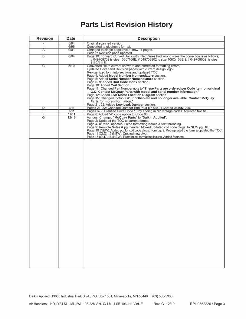
Revision Date Description - 5/94 Original scanned version. - 6/96 Converted to electronic format. A 9/01 Changed to single page layout, now 11 pages. Page 2: Revision page updated B 8/04 Page 10: Forward Curved Units with Inlet Vanes had wrong sizes the correction is as follows; # 049708702 is size 106C/106E, # 049708802 is size 108C/108E & # 049709002 is size 111C/111E. C 5/10 Converted file to current software and corrected formatting errors. Updated Cover and Revision pages with current design logo. Reorganized form into sections and updated TOC. Page 4: Added Model Number Nomenclature section. Page 5: Added Serial Number Nomenclature section. Page 6- 9: Added Unit Code Index section. Page 10: Added Coil Section. Page 11: Changed Part Number note to "These Parts are ordered per Code Item on original G.O. Contact McQuay Parts with model and serial number information" Page 12: Added LSB Motor Location Diagram section. Page 15: Changed footnote #1 to "Obsolete and no longer available. Contact McQuay Parts for more information." Page 21, 22: Added Low Leak Damper section. D 4/11 Pages 21, 22: Changed Damper End Plug p/n 044951206 to 044961206. E 7/11 Pages 6- 9: Clarified Drive Code 13 by adding in "C" vintage codes. Adjusted text fit. F 11/11 Page 6: Added "A" code option to Code 06. G 12/19 Various: Changed "McQuay Parts" to "Daikin Applied". Page 2: Updated the TOC to current format. Page 4- 8: Misc. updates. Fixed formatting issues & text threading. Page 9: Rewrote Notes & pg. header. Moved updated coil code dwgs. to NEW pg. 10. Page 10 (NEW): Added pg. for coil code dwgs. from pg. 9. Repaginated the form & updated the TOC. Page 11 (OLD) 12 (NEW): Created new dwg. Page 15 (OLD) 16 (NEW): Fixed misc. formatting issues. Added footnote.
Air Handlers; LHD,LYF,LSL,LML,LWL 103-228 Vint. C/ LML,LSB 106-111 Vint. E Rev. G 12/19 RPL 0552226 / Page 5
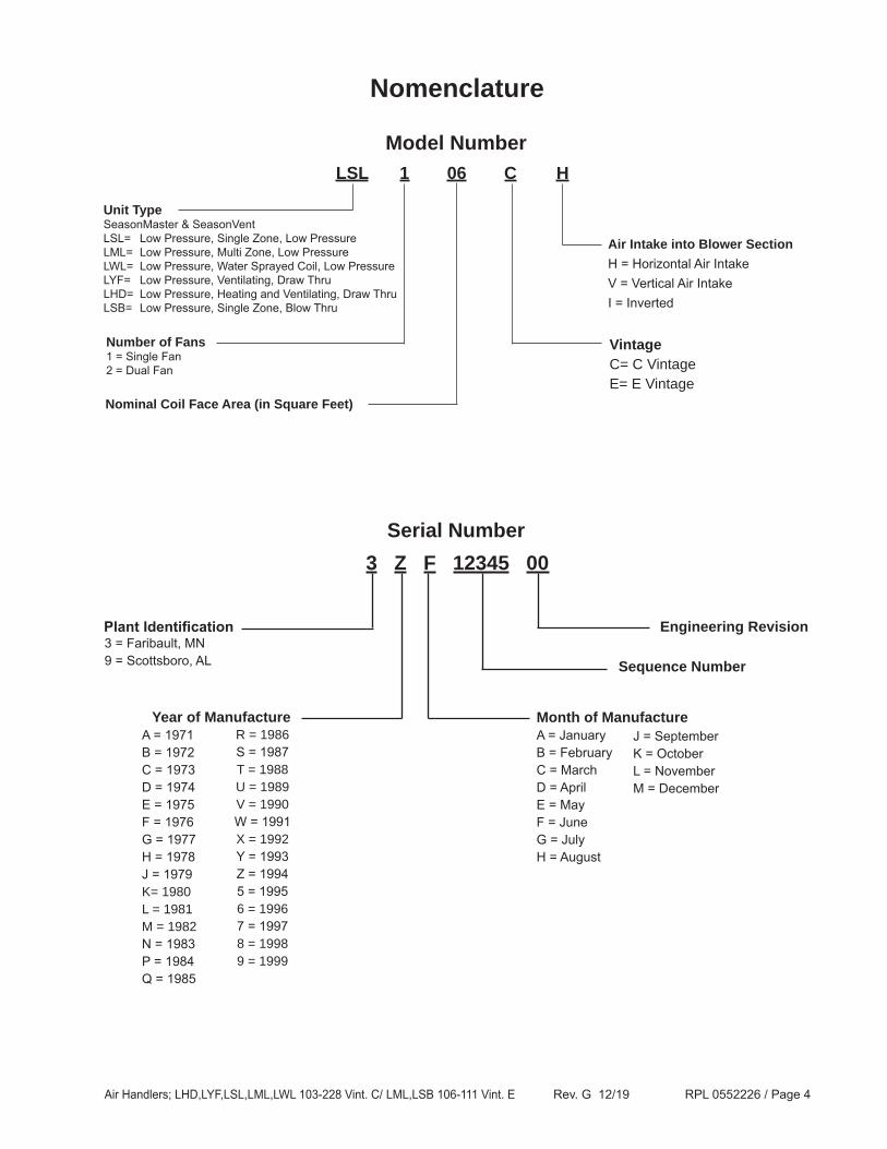
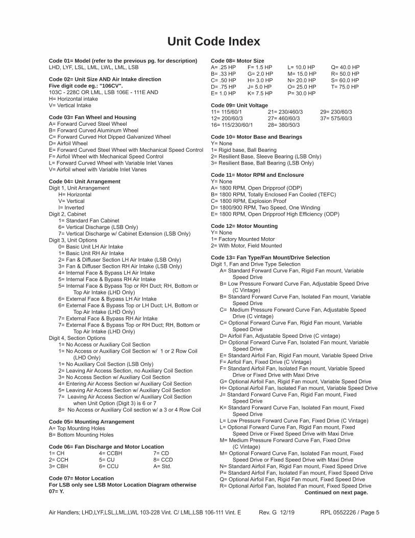
Unit Code IndexCode 01= Model (refer to the previous pg. for description)LHD, LYF, LSL, LML, LWL, LML, LSB
Code 02= Unit Size AND Air Intake direction Five digit code eg.: "106CV".103C - 228C OR LML, LSB 106E - 111E ANDH= Horizontal intakeV= Vertical Intake
Code 03= Fan Wheel and HousingA= Forward Curved Steel WheelB= Forward Curved Aluminum WheelC= Forward Curved Hot Dipped Galvanized WheelD= Airfoil WheelE= Forward Curved Steel Wheel with Mechanical Speed ControlF= Airfoil Wheel with Mechanical Speed ControlL= Forward Curved Wheel with Variable Inlet VanesV= Airfoil wheel with Variable Inlet Vanes
Code 04= Unit ArrangementDigit 1, Unit Arrangement H= Horizontal V= Vertical I= InvertedDigit 2, Cabinet 1= Standard Fan Cabinet 6= Vertical Discharge (LSB Only) 7= Vertical Discharge w/ Cabinet Extension (LSB Only)Digit 3, Unit Options 0= Basic Unit LH Air Intake 1= Basic Unit RH Air Intake 2= Fan & Diffuser Section LH Air Intake (LSB Only) 3= Fan & Diffuser Section RH Air Intake (LSB Only) 4= Internal Face & Bypass LH Air Intake 5= Internal Face & Bypass RH Air Intake 5= Internal Face & Bypass Top or RH Duct; RH, Bottom or Top Air Intake (LHD Only) 6= External Face & Bypass LH Air Intake 6= External Face & Bypass Top or LH Duct; LH, Bottom or Top Air Intake (LHD Only) 7= External Face & Bypass RH Air Intake 7= External Face & Bypass Top or RH Duct; RH, Bottom or Top Air Intake (LHD Only)Digit 4, Section Options 1= No Access or Auxiliary Coil Section 1= No Access or Auxiliary Coil Section w/ 1 or 2 Row Coil (LHD Only) 1= No Auxiliary Coil Section (LSB Only) 2= Leaving Air Access Section, no Auxiliary Coil Section 3= No Access Section w/ Auxiliary Coil Section 4= Entering Air Access Section w/ Auxiliary Coil Section 5= Leaving Air Access Section w/ Auxiliary Coil Section 7= Leaving Air Access Section w/ Auxiliary Coil Section when Unit Option (Digit 3) is 6 or 7 8= No Access or Auxiliary Coil section w/ a 3 or 4 Row Coil
Code 05= Mounting ArrangementA= Top Mounting HolesB= Bottom Mounting Holes
Code 06= Fan Discharge and Motor Location1= CH 4= CCBH 7= CD2= CCH 5= CU 8= CCD3= CBH 6= CCU A= Std.
Code 07= Motor LocationFor LSB only see LSB Motor Location Diagram otherwise 07= Y.
Code 08= Motor SizeA= .25 HP F= 1.5 HP L= 10.0 HP Q= 40.0 HPB= .33 HP G= 2.0 HP M= 15.0 HP R= 50.0 HPC= .50 HP H= 3.0 HP N= 20.0 HP S= 60.0 HPD= .75 HP J= 5.0 HP O= 25.0 HP T= 75.0 HPE= 1.0 HP K= 7.5 HP P= 30.0 HP
Code 10= Motor Base and BearingsY= None1= Rigid base, Ball Bearing2= Resilient Base, Sleeve Bearing (LSB Only)3= Resilient Base, Ball Bearing (LSB Only)
Code 11= Motor RPM and EnclosureY= NoneA= 1800 RPM, Open Dripproof (ODP)B= 1800 RPM, Totally Enclosed Fan Cooled (TEFC)C= 1800 RPM, Explosion ProofD= 1800/900 RPM, Two Speed, One WindingE= 1800 RPM, Open Dripproof High Efficiency (ODP)
Code 12= Motor Mounting Y= None 1= Factory Mounted Motor2= With Motor, Field Mounted
Code 13= Fan Type/Fan Mount/Drive SelectionDigit 1, Fan and Drive Type Selection A= Standard Forward Curve Fan, Rigid Fan mount, Variable
Speed Drive or Fixed Speed Drive with Maxi Drive M= Medium Pressure Forward Curve Fan, Fixed Drive (C Vintage) M= Optional Forward Curve Fan, Isolated Fan mount, Fixed
Speed Drive or Fixed Speed Drive with Maxi Drive N= Standard Airfoil Fan, Rigid Fan mount, Fixed Speed Drive P= Standard Airfoil Fan, Isolated Fan mount, Fixed Speed Drive Q= Optional Airfoil Fan, Rigid Fan mount, Fixed Speed Drive R= Optional Airfoil Fan, Isolated Fan mount, Fixed Speed Drive Continued on next page.
Air Handlers; LHD,LYF,LSL,LML,LWL 103-228 Vint. C/ LML,LSB 106-111 Vint. E Rev. G 12/19 RPL 0552226 / Page 6
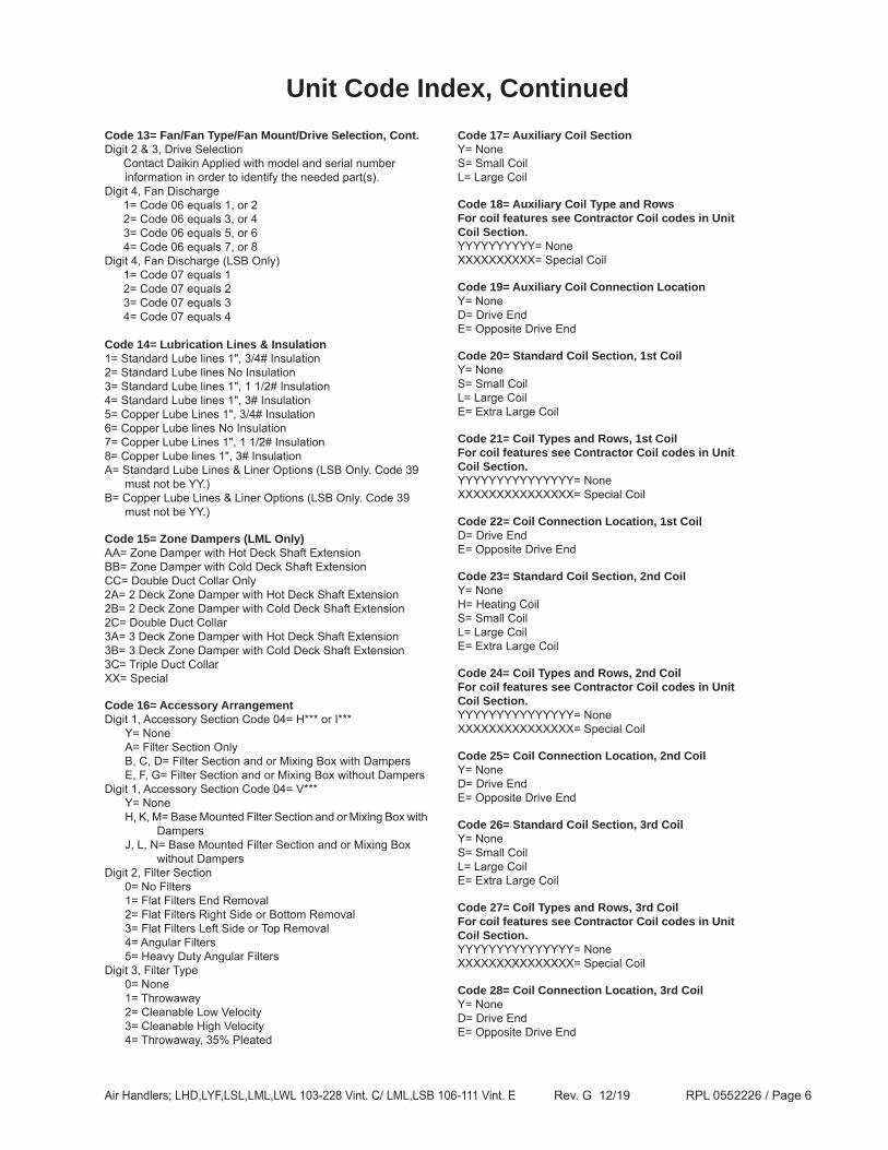
Code 13= Fan/Fan Type/Fan Mount/Drive Selection, Cont.Digit 2 & 3, Drive Selection Contact Daikin Applied with model and serial number
information in order to identify the needed part(s).Digit 4, Fan Discharge 1= Code 06 equals 1, or 2 2= Code 06 equals 3, or 4 3= Code 06 equals 5, or 6 4= Code 06 equals 7, or 8Digit 4, Fan Discharge (LSB Only) 1= Code 07 equals 1 2= Code 07 equals 2 3= Code 07 equals 3 4= Code 07 equals 4
Code 14= Lubrication Lines & Insulation1= Standard Lube lines 1", 3/4# Insulation2= Standard Lube lines No Insulation3= Standard Lube lines 1", 1 1/2# Insulation4= Standard Lube lines 1", 3# Insulation5= Copper Lube Lines 1", 3/4# Insulation6= Copper Lube lines No Insulation7= Copper Lube Lines 1", 1 1/2# Insulation8= Copper Lube lines 1", 3# InsulationA= Standard Lube Lines & Liner Options (LSB Only. Code 39 must not be YY.)B= Copper Lube Lines & Liner Options (LSB Only. Code 39 must not be YY.)
Code 15= Zone Dampers (LML Only)AA= Zone Damper with Hot Deck Shaft ExtensionBB= Zone Damper with Cold Deck Shaft ExtensionCC= Double Duct Collar Only2A= 2 Deck Zone Damper with Hot Deck Shaft Extension2B= 2 Deck Zone Damper with Cold Deck Shaft Extension2C= Double Duct Collar3A= 3 Deck Zone Damper with Hot Deck Shaft Extension3B= 3 Deck Zone Damper with Cold Deck Shaft Extension3C= Triple Duct CollarXX= Special
Code 16= Accessory Arrangement Digit 1, Accessory Section Code 04= H*** or I*** Y= None A= Filter Section Only B, C, D= Filter Section and or Mixing Box with Dampers E, F, G= Filter Section and or Mixing Box without DampersDigit 1, Accessory Section Code 04= V*** Y= None H, K, M= Base Mounted Filter Section and or Mixing Box with Dampers J, L, N= Base Mounted Filter Section and or Mixing Box without DampersDigit 2, Filter Section 0= No Filters 1= Flat Filters End Removal 2= Flat Filters Right Side or Bottom Removal 3= Flat Filters Left Side or Top Removal 4= Angular Filters 5= Heavy Duty Angular FiltersDigit 3, Filter Type 0= None 1= Throwaway 2= Cleanable Low Velocity 3= Cleanable High Velocity 4= Throwaway, 35% Pleated
Code 17= Auxiliary Coil SectionY= NoneS= Small CoilL= Large Coil
Code 18= Auxiliary Coil Type and Rows For coil features see Contractor Coil codes in Unit Coil Section.YYYYYYYYYY= NoneXXXXXXXXXX= Special Coil
Code 20= Standard Coil Section, 1st CoilY= NoneS= Small CoilL= Large CoilE= Extra Large Coil
Code 21= Coil Types and Rows, 1st Coil For coil features see Contractor Coil codes in Unit Coil Section.YYYYYYYYYYYYYYY= NoneXXXXXXXXXXXXXXX= Special Coil
Code 23= Standard Coil Section, 2nd CoilY= NoneH= Heating CoilS= Small CoilL= Large CoilE= Extra Large Coil
Code 24= Coil Types and Rows, 2nd Coil For coil features see Contractor Coil codes in Unit Coil Section.YYYYYYYYYYYYYYY= NoneXXXXXXXXXXXXXXX= Special Coil
Code 26= Standard Coil Section, 3rd CoilY= NoneS= Small CoilL= Large CoilE= Extra Large Coil
Code 27= Coil Types and Rows, 3rd Coil For coil features see Contractor Coil codes in Unit Coil Section.YYYYYYYYYYYYYYY= NoneXXXXXXXXXXXXXXX= Special Coil
Air Handlers; LHD,LYF,LSL,LML,LWL 103-228 Vint. C/ LML,LSB 106-111 Vint. E Rev. G 12/19 RPL 0552226 / Page 7
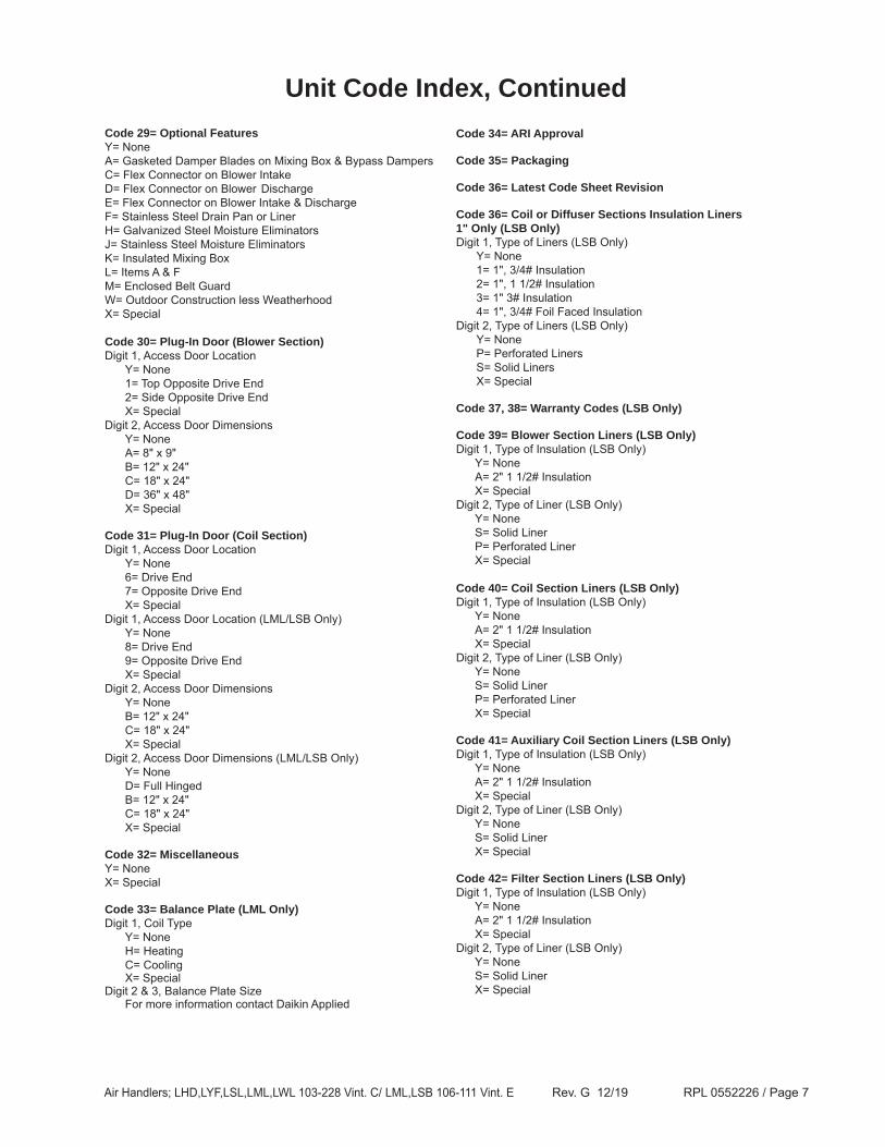
Code 29= Optional FeaturesY= None A= Gasketed Damper Blades on Mixing Box & Bypass DampersC= Flex Connector on Blower Intake D= Flex Connector on Blower Discharge E= Flex Connector on Blower Intake & Discharge F= Stainless Steel Drain Pan or Liner H= Galvanized Steel Moisture Eliminators J= Stainless Steel Moisture EliminatorsK= Insulated Mixing BoxL= Items A & FM= Enclosed Belt GuardW= Outdoor Construction less WeatherhoodX= Special
Code 30= Plug-In Door (Blower Section)Digit 1, Access Door Location Y= None 1= Top Opposite Drive End 2= Side Opposite Drive End X= SpecialDigit 2, Access Door Dimensions Y= None A= 8" x 9" B= 12" x 24" C= 18" x 24" D= 36" x 48" X= Special
Code 31= Plug-In Door (Coil Section)Digit 1, Access Door Location Y= None 6= Drive End 7= Opposite Drive End X= SpecialDigit 1, Access Door Location (LML/LSB Only) Y= None 8= Drive End 9= Opposite Drive End X= SpecialDigit 2, Access Door Dimensions Y= None B= 12" x 24" C= 18" x 24" X= SpecialDigit 2, Access Door Dimensions (LML/LSB Only) Y= None D= Full Hinged B= 12" x 24" C= 18" x 24" X= Special
Code 32= Miscellaneous Y= NoneX= Special
Code 33= Balance Plate (LML Only)Digit 1, Coil Type Y= None H= Heating C= Cooling X= SpecialDigit 2 & 3, Balance Plate Size For more information contact Daikin Applied
Unit Code Index, ContinuedCode 34= ARI Approval
Code 35= Packaging
Code 36= Latest Code Sheet Revision
Code 36= Coil or Diffuser Sections Insulation Liners 1" Only (LSB Only)Digit 1, Type of Liners (LSB Only) Y= None 1= 1", 3/4# Insulation 2= 1", 1 1/2# Insulation 3= 1" 3# Insulation 4= 1", 3/4# Foil Faced InsulationDigit 2, Type of Liners (LSB Only) Y= None P= Perforated Liners S= Solid Liners X= Special
Code 37, 38= Warranty Codes (LSB Only)
Code 39= Blower Section Liners (LSB Only)Digit 1, Type of Insulation (LSB Only) Y= None A= 2" 1 1/2# Insulation X= SpecialDigit 2, Type of Liner (LSB Only) Y= None S= Solid Liner P= Perforated Liner X= Special Code 40= Coil Section Liners (LSB Only)Digit 1, Type of Insulation (LSB Only) Y= None A= 2" 1 1/2# Insulation X= SpecialDigit 2, Type of Liner (LSB Only) Y= None S= Solid Liner P= Perforated Liner X= Special
Code 41= Auxiliary Coil Section Liners (LSB Only)Digit 1, Type of Insulation (LSB Only) Y= None A= 2" 1 1/2# Insulation X= SpecialDigit 2, Type of Liner (LSB Only) Y= None S= Solid Liner X= Special
Code 42= Filter Section Liners (LSB Only)Digit 1, Type of Insulation (LSB Only) Y= None A= 2" 1 1/2# Insulation X= SpecialDigit 2, Type of Liner (LSB Only) Y= None S= Solid Liner X= Special
Air Handlers; LHD,LYF,LSL,LML,LWL 103-228 Vint. C/ LML,LSB 106-111 Vint. E Rev. G 12/19 RPL 0552226 / Page 8
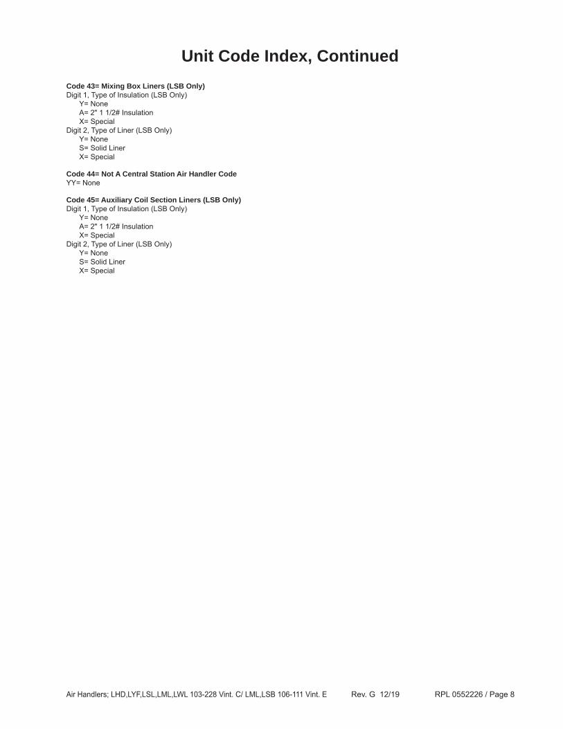
Unit Code Index, ContinuedCode 43= Mixing Box Liners (LSB Only)Digit 1, Type of Insulation (LSB Only) Y= None A= 2" 1 1/2# Insulation X= SpecialDigit 2, Type of Liner (LSB Only) Y= None S= Solid Liner X= Special
Code 44= Not A Central Station Air Handler CodeYY= None
Code 45= Auxiliary Coil Section Liners (LSB Only)Digit 1, Type of Insulation (LSB Only) Y= None A= 2" 1 1/2# Insulation X= SpecialDigit 2, Type of Liner (LSB Only) Y= None S= Solid Liner X= Special
Air Handlers; LHD,LYF,LSL,LML,LWL 103-228 Vint. C/ LML,LSB 106-111 Vint. E Rev. G 12/19 RPL 0552226 / Page 9
CoilsNotes
All Central Station Air Handlers use Contractor style Heating, Cooling, Reheat, and/or DX Coils. Contractor Coils are offered in multiple fin heights to allow the user to select the coil size to match the air flow. Contractor Coils offer a wider range of circuitings, rows and fins, and materials than the standard Unit Coil.
Contractor Coils are always quoted as needed when needed, so they DO NOT HAVE STANDARD ORDERABLE OR “HARD/PERMANENT” NINE DIGIT DAIKIN APPLIED PART NUMBERS.
When a replacement Coil is required, a Contractor Coil quote needs to be prepared. To quote a replacement Contractor Coil it is necessary to obtain model and serial number information from the Unit Nameplate and then contact Daikin Applied.
If the unit has more than one Coil it will also be necessary to confirm which Coil(s) are needed BEFORE quoting. If there is more than one coil in the unit, confirm WHICH coil is needed and the TOTAL NUMBER of coils required BEFORE ordering.
In some instances coils were manufactured separately from the unit and may have a unique serial number eg.: 9Z12345-00. A coil with a serial number starting with a "9" was built in Scottsboro AL and may or may not have been installed in a unit before shipment.
Note that the sample code strings shown on the following page are INCOMPLETE and DO NOT furnish enough information for Daikin Applied to quote. General Order (GO) and/or serial number information is required in order to properly quote a Contractor Coil.
Air Handlers; LHD,LYF,LSL,LML,LWL 103-228 Vint. C/ LML,LSB 106-111 Vint. E Rev. G 12/19 RPL 0552226 / Page 10
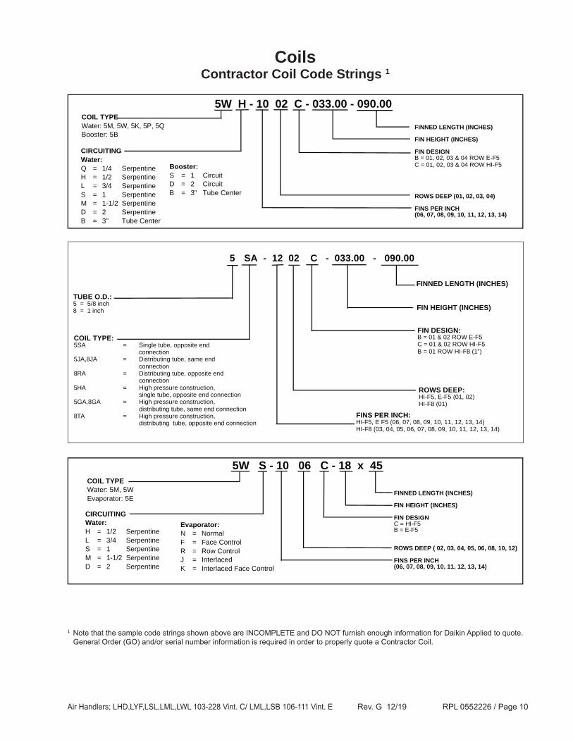
CoilsContractor Coil Code Strings 1
5W H - 10 02 C - 033.00 - 090.00COIL TYPEWater: 5M, 5W, 5K, 5P, 5QBooster: 5B
Evaporator:N = NormalF = Face ControlR = Row ControlJ = InterlacedK = Interlaced Face Control
FINNED LENGTH (INCHES)
FIN HEIGHT (INCHES)
FIN DESIGNC = HI-F5B = E-F5
ROWS DEEP ( 02, 03, 04, 05, 06, 08, 10, 12)
FINS PER INCH(06, 07, 08, 09, 10, 11, 12, 13, 14)
1 Note that the sample code strings shown above are INCOMPLETE and DO NOT furnish enough information for Daikin Applied to quote. General Order (GO) and/or serial number information is required in order to properly quote a Contractor Coil.
Air Handlers; LHD,LYF,LSL,LML,LWL 103-228 Vint. C/ LML,LSB 106-111 Vint. E Rev. G 12/19 RPL 0552226 / Page 11
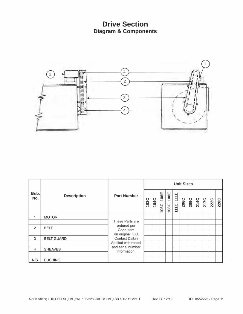
1 MOTOR •
2 BELT •
3 BELT GUARD •
4 SHEAVES •
N/S BUSHING •
Drive SectionDiagram & Components
Unit Sizes
103C
104C
106C
, 106
E
108C
, 108
E
111C
, 111
E
206C
209C
214C
217C
222C
228C
DescriptionBub.No. Part Number
1
1
3
2
4
4
These Parts are ordered per Code Item
on original G.O.Contact Daikin
Applied with model and serial number
information.
Air Handlers; LHD,LYF,LSL,LML,LWL 103-228 Vint. C/ LML,LSB 106-111 Vint. E Rev. G 12/19 RPL 0552226 / Page 12
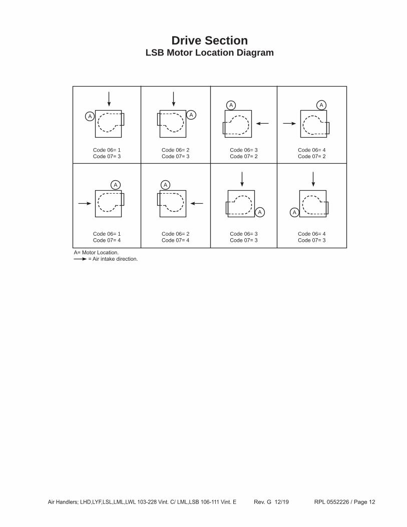
Drive SectionLSB Motor Location Diagram
A= Motor Location. = Air intake direction.
Code 06= 1Code 07= 3
A A
A
A
A
Code 06= 2Code 07= 3
Code 06= 3Code 07= 2
Code 06= 4Code 07= 2
A
Code 06= 1Code 07= 4
Code 06= 2Code 07= 4
Code 06= 3Code 07= 3
Code 06= 4Code 07= 3
A
A
Air Handlers; LHD,LYF,LSL,LML,LWL 103-228 Vint. C/ LML,LSB 106-111 Vint. E Rev. G 12/19 RPL 0552226 / Page 13
48 56 143T
145T
182T
184T
213T
215T
254T
256T
284T
286T
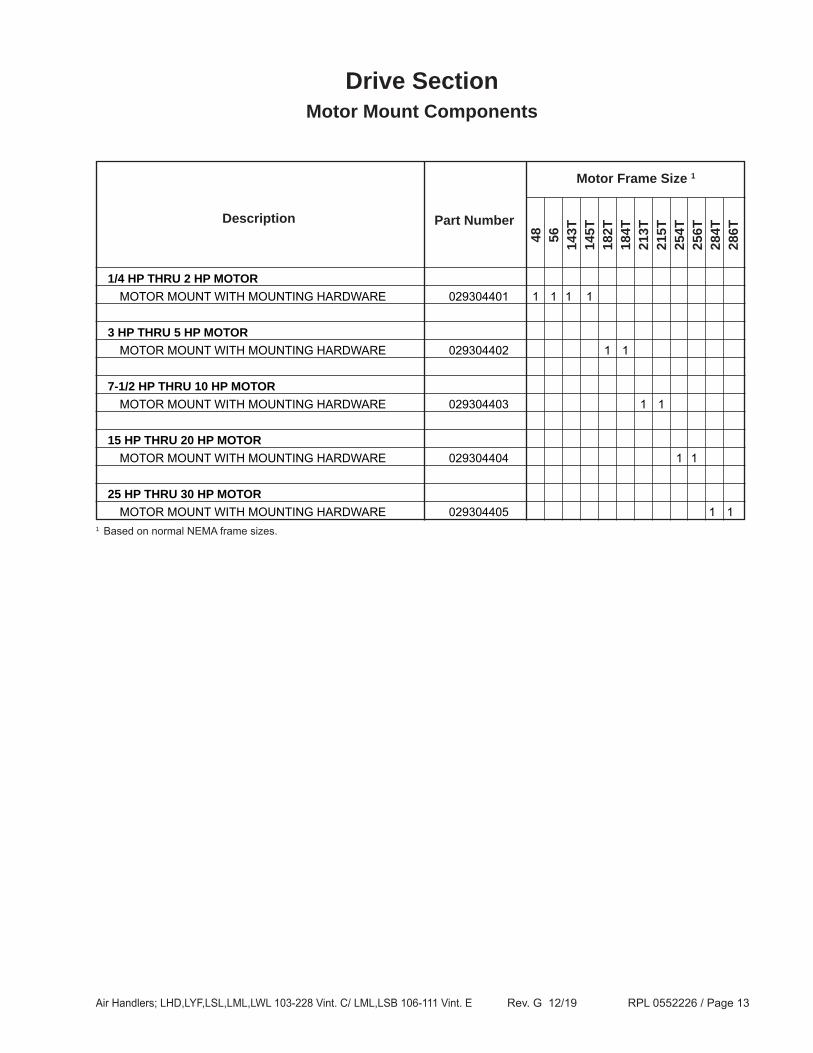
Drive SectionMotor Mount Components
Motor Frame Size 1
Description Part Number
1/4 HP THRU 2 HP MOTOR MOTOR MOUNT WITH MOUNTING HARDWARE 029304401 1 1 1 1
3 HP THRU 5 HP MOTOR MOTOR MOUNT WITH MOUNTING HARDWARE 029304402 1 1
7-1/2 HP THRU 10 HP MOTOR MOTOR MOUNT WITH MOUNTING HARDWARE 029304403 1 1
15 HP THRU 20 HP MOTOR MOTOR MOUNT WITH MOUNTING HARDWARE 029304404 1 1
25 HP THRU 30 HP MOTOR MOTOR MOUNT WITH MOUNTING HARDWARE 029304405 1 11 Based on normal NEMA frame sizes.
Air Handlers; LHD,LYF,LSL,LML,LWL 103-228 Vint. C/ LML,LSB 106-111 Vint. E Rev. G 12/19 RPL 0552226 / Page 14
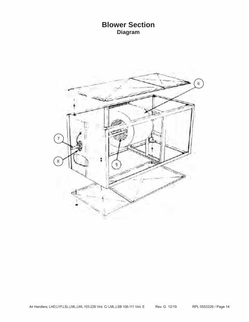
Blower SectionDiagram
13 8
7
6
Air Handlers; LHD,LYF,LSL,LML,LWL 103-228 Vint. C/ LML,LSB 106-111 Vint. E Rev. G 12/19 RPL 0552226 / Page 15
103C
104C
106C
, 106
E
108C
, 108
E
111C
, 111
E
206C
209C
214C
217C
222C
228C
Unit Sizes
DescriptionBub.No. Part Number
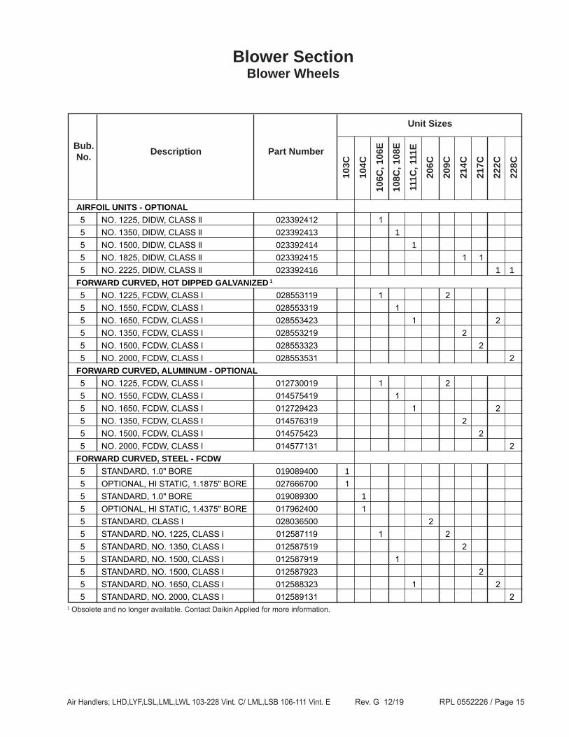
Blower SectionBlower Wheels
1 Obsolete and no longer available. Contact Daikin Applied for more information.
AIRFOIL UNITS - OPTIONAL 5 NO. 1225, DIDW, CLASS ll 023392412 1 5 NO. 1350, DIDW, CLASS ll 023392413 1 5 NO. 1500, DIDW, CLASS ll 023392414 1 5 NO. 1825, DIDW, CLASS ll 023392415 1 1 5 NO. 2225, DIDW, CLASS ll 023392416 1 1 FORWARD CURVED, HOT DIPPED GALVANIZED 1 5 NO. 1225, FCDW, CLASS l 028553119 1 2 5 NO. 1550, FCDW, CLASS l 028553319 1 5 NO. 1650, FCDW, CLASS l 028553423 1 2 5 NO. 1350, FCDW, CLASS l 028553219 2 5 NO. 1500, FCDW, CLASS l 028553323 2 5 NO. 2000, FCDW, CLASS l 028553531 2 FORWARD CURVED, ALUMINUM - OPTIONAL 5 NO. 1225, FCDW, CLASS l 012730019 1 2 5 NO. 1550, FCDW, CLASS l 014575419 1 5 NO. 1650, FCDW, CLASS l 012729423 1 2 5 NO. 1350, FCDW, CLASS l 014576319 2 5 NO. 1500, FCDW, CLASS l 014575423 2 5 NO. 2000, FCDW, CLASS l 014577131 2 FORWARD CURVED, STEEL - FCDW 5 STANDARD, 1.0" BORE 019089400 1 5 OPTIONAL, HI STATIC, 1.1875" BORE 027666700 1 5 STANDARD, 1.0" BORE 019089300 1 5 OPTIONAL, HI STATIC, 1.4375" BORE 017962400 1 5 STANDARD, CLASS l 028036500 2 5 STANDARD, NO. 1225, CLASS l 012587119 1 2 5 STANDARD, NO. 1350, CLASS l 012587519 2 5 STANDARD, NO. 1500, CLASS l 012587919 1 5 STANDARD, NO. 1500, CLASS l 012587923 2 5 STANDARD, NO. 1650, CLASS l 012588323 1 2 5 STANDARD, NO. 2000, CLASS l 012589131 2
Air Handlers; LHD,LYF,LSL,LML,LWL 103-228 Vint. C/ LML,LSB 106-111 Vint. E Rev. G 12/19 RPL 0552226 / Page 16
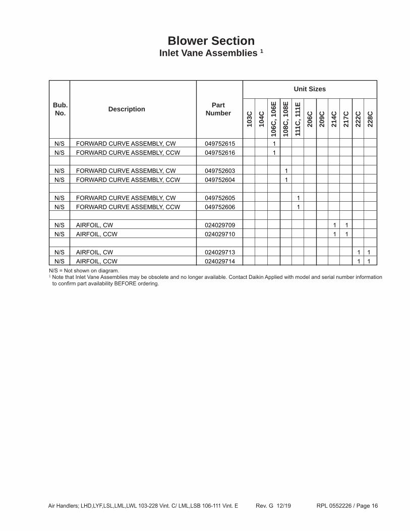
N/S AIRFOIL, CW 024029713 1 1 N/S AIRFOIL, CCW 024029714 1 1N/S = Not shown on diagram.1 Note that Inlet Vane Assemblies may be obsolete and no longer available. Contact Daikin Applied with model and serial number information
to confirm part availability BEFORE ordering.
Air Handlers; LHD,LYF,LSL,LML,LWL 103-228 Vint. C/ LML,LSB 106-111 Vint. E Rev. G 12/19 RPL 0552226 / Page 17
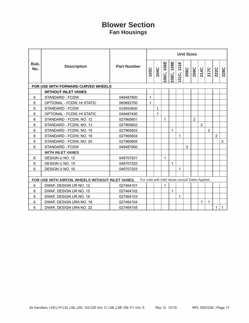
Blower SectionFan Housings
Unit Sizes
103C
104C
106C
, 106
E
108C
, 108
E
111C
, 111
E
206C
209C
214C
217C
222C
228C
DescriptionBub.No. Part Number
For units with Inlet Vanes consult Daikin Applied.
FOR USE WITH FORWARD CURVED WHEELS WITHOUT INLET VANES 6 STANDARD - FCDW 049487800 1 6 OPTIONAL - FCDW, HI STATIC 065892700 1 6 STANDARD - FCDW 019093600 1 6 OPTIONAL - FCDW, HI STATIC 049487400 1 6 STANDARD - FCDW, NO. 12 027965601 1 2 6 STANDARD - FCDW, NO. 13 027965602 2 6 STANDARD - FCDW, NO. 15 027965603 1 2 6 STANDARD - FCDW, NO. 16 027965604 1 2 6 STANDARD - FCDW, NO. 20 027965605 2 6 STANDARD - FCDW 049487900 2 WITH INLET VANES 6 DESIGN U NO. 12 049707201 1 6 DESIGN U NO. 15 049707202 1 6 DESIGN U NO. 16 049707203 1
FOR USE WITH AIRFOIL WHEELS WITHOUT INLET VANES. 6 DWAF, DESIGN UR NO. 12 027464101 1 6 DWAF, DESIGN UR NO. 15 027464102 1 6 DWAF, DESIGN UR NO. 16 027464103 1 6 DWAF, DESIGN URA NO. 18 027464104 1 1 6 DWAF, DESIGN URA NO. 22 027464105 1 1
Air Handlers; LHD,LYF,LSL,LML,LWL 103-228 Vint. C/ LML,LSB 106-111 Vint. E Rev. G 12/19 RPL 0552226 / Page 18
Unit Sizes
103C
104C
106C
, 106
E
108C
, 108
E
111C
, 111
E
206C
209C
214C
217C
222C
228C
DescriptionBub.No. Part Number
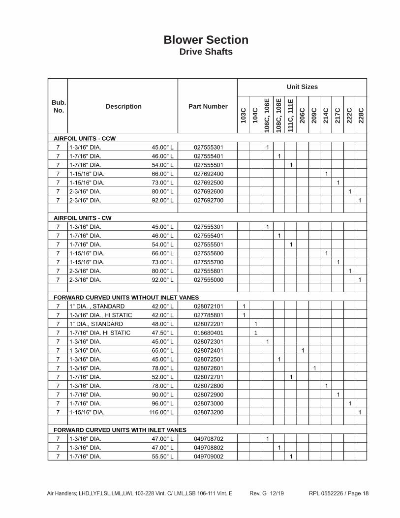
Blower SectionDrive Shafts
AIRFOIL UNITS - CCW 7 1-3/16" DIA. 45.00" L 027555301 1 7 1-7/16" DIA. 46.00" L 027555401 1 7 1-7/16" DIA. 54.00" L 027555501 1 7 1-15/16" DIA. 66.00" L 027692400 1 7 1-15/16" DIA. 73.00" L 027692500 1 7 2-3/16" DIA. 80.00" L 027692600 1 7 2-3/16" DIA. 92.00" L 027692700 1
AIRFOIL UNITS - CW 7 1-3/16" DIA. 45.00" L 027555301 1 7 1-7/16" DIA. 46.00" L 027555401 1 7 1-7/16" DIA. 54.00" L 027555501 1 7 1-15/16" DIA. 66.00" L 027555600 1 7 1-15/16" DIA. 73.00" L 027555700 1 7 2-3/16" DIA. 80.00" L 027555801 1 7 2-3/16" DIA. 92.00" L 027555000 1
FORWARD CURVED UNITS WITHOUT INLET VANES 7 1" DIA. , STANDARD 42.00" L 028072101 1 7 1-3/16" DIA., HI STATIC 42.00" L 027785801 1 7 1" DIA., STANDARD 48.00" L 028072201 1 7 1-7/16" DIA. HI STATIC 47.50" L 016680401 1 7 1-3/16" DIA. 45.00" L 028072301 1 7 1-3/16" DIA. 65.00" L 028072401 1 7 1-3/16" DIA. 45.00" L 028072501 1 7 1-3/16" DIA. 78.00" L 028072601 1 7 1-7/16" DIA. 52.00" L 028072701 1 7 1-3/16" DIA. 78.00" L 028072800 1 7 1-7/16" DIA. 90.00" L 028072900 1 7 1-7/16" DIA. 96.00" L 028073000 1 7 1-15/16" DIA. 116.00" L 028073200 1
FORWARD CURVED UNITS WITH INLET VANES 7 1-3/16" DIA. 47.00" L 049708702 1 7 1-3/16" DIA. 47.00" L 049708802 1 7 1-7/16" DIA. 55.50" L 049709002 1
Air Handlers; LHD,LYF,LSL,LML,LWL 103-228 Vint. C/ LML,LSB 106-111 Vint. E Rev. G 12/19 RPL 0552226 / Page 19
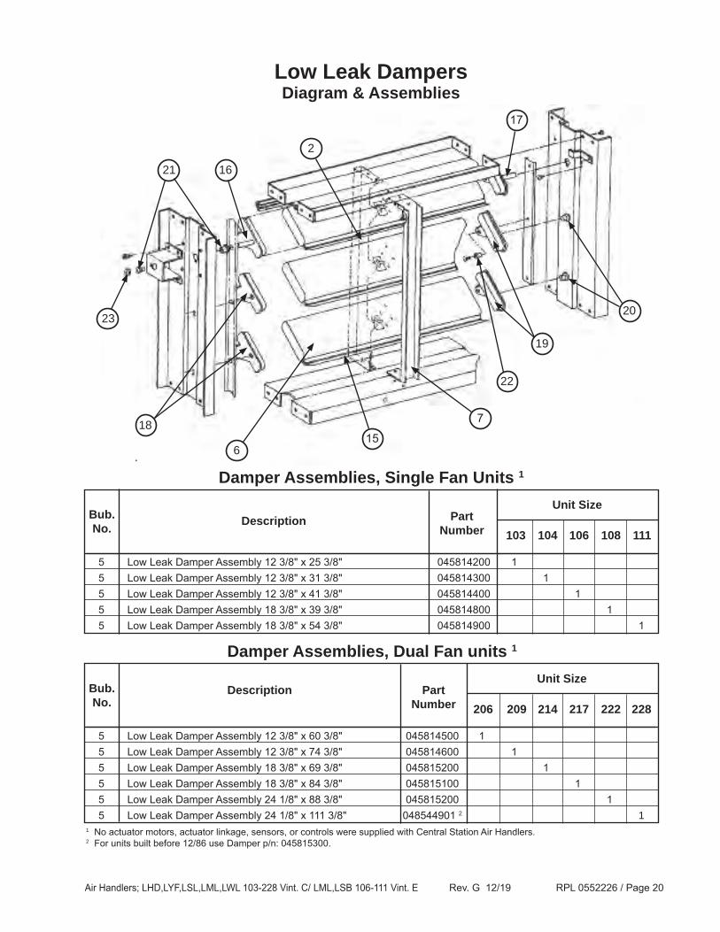
1 No actuator motors, actuator linkage, sensors, or controls were supplied with Central Station Air Handlers.2 For units built before 12/86 use Damper p/n: 045815300.
Description
Description
Air Handlers; LHD,LYF,LSL,LML,LWL 103-228 Vint. C/ LML,LSB 106-111 Vint. E Rev. G 12/19 RPL 0552226 / Page 21
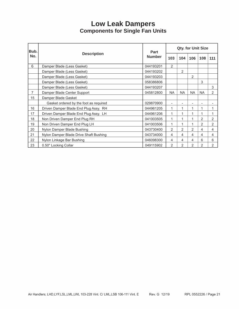
Low Leak DampersComponents for Single Fan Units
6 Damper Blade (Less Gasket) 044193201 2 Damper Blade (Less Gasket) 044193202 2 Damper Blade (Less Gasket) 044193203 2 Damper Blade (Less Gasket) 058386806 3 Damper Blade (Less Gasket) 044193207 3 7 Damper Blade Center Support 045812800 NA NA NA NA 2 15 Damper Blade Gasket Gasket ordered by the foot as required 029870900 - - - - - 16 Driven Damper Blade End Plug Assy. RH 044961205 1 1 1 1 1 17 Driven Damper Blade End Plug Assy. LH 044961206 1 1 1 1 1 18 Non Driven Damper End Plug RH 041003505 1 1 1 2 2 19 Non Driven Damper End Plug LH 041003506 1 1 1 2 2 20 Nylon Damper Blade Bushing 043730400 2 2 2 4 4 21 Nylon Damper Blade Drive Shaft Bushing 043734000 4 4 4 4 4 22 Nylon Linkage Bar Bushing 046098300 4 4 4 6 6 23 0.50" Locking Collar 049115902 2 2 2 2 2
111108106104103Description
PartNumber
Qty. for Unit SizeBub.No.
Air Handlers; LHD,LYF,LSL,LML,LWL 103-228 Vint. C/ LML,LSB 106-111 Vint. E Rev. G 12/19 RPL 0552226 / Page 22
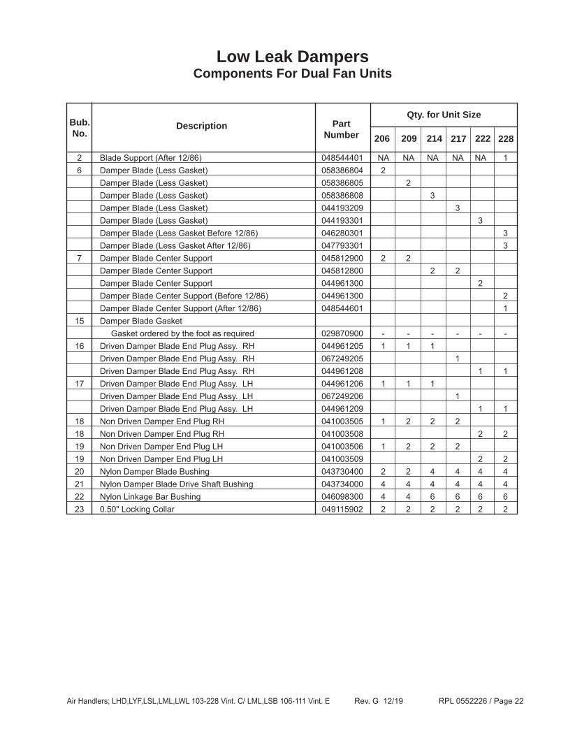
Low Leak DampersComponents For Dual Fan Units
2 Blade Support (After 12/86) 048544401 NA NA NA NA NA 1 6 Damper Blade (Less Gasket) 058386804 2 Damper Blade (Less Gasket) 058386805 2 Damper Blade (Less Gasket) 058386808 3 Damper Blade (Less Gasket) 044193209 3 Damper Blade (Less Gasket) 044193301 3 Damper Blade (Less Gasket Before 12/86) 046280301 3 Damper Blade (Less Gasket After 12/86) 047793301 3 7 Damper Blade Center Support 045812900 2 2 Damper Blade Center Support 045812800 2 2 Damper Blade Center Support 044961300 2 Damper Blade Center Support (Before 12/86) 044961300 2 Damper Blade Center Support (After 12/86) 048544601 1 15 Damper Blade Gasket Gasket ordered by the foot as required 029870900 - - - - - - 16 Driven Damper Blade End Plug Assy. RH 044961205 1 1 1 Driven Damper Blade End Plug Assy. RH 067249205 1 Driven Damper Blade End Plug Assy. RH 044961208 1 1 17 Driven Damper Blade End Plug Assy. LH 044961206 1 1 1 Driven Damper Blade End Plug Assy. LH 067249206 1 Driven Damper Blade End Plug Assy. LH 044961209 1 1 18 Non Driven Damper End Plug RH 041003505 1 2 2 2 18 Non Driven Damper End Plug RH 041003508 2 2 19 Non Driven Damper End Plug LH 041003506 1 2 2 2 19 Non Driven Damper End Plug LH 041003509 2 2 20 Nylon Damper Blade Bushing 043730400 2 2 4 4 4 4 21 Nylon Damper Blade Drive Shaft Bushing 043734000 4 4 4 4 4 4 22 Nylon Linkage Bar Bushing 046098300 4 4 6 6 6 6 23 0.50" Locking Collar 049115902 2 2 2 2 2 2