28 TRANSPORTATION RESEARCH RECORD 1211 Measuring Rate of Corrosion of Steel in Field Concrete Structures KENNETH c. CLEAR Three-electrode linear polarization testing has become a val- uable tool for measuring the corrosion rate of reinforcing steel in concrete. Discussion covers the test technique, procedures, and specially constructed portable equipment used to collect valid and useful data to help project future distress and its rate, and in defining the effectiveness of rehabilitations. Guide- lines are presented for use in data interpretation. In the mid-1970s, researchers recognized that the "missing link" in the area of corrosion of steel in concrete was the inability to define rate of corrosion nondestructively. Con- ventional methods of assessing condition put great emphasis on close examination of physical evidence of corrosion dis- tress. The presence of undue cracking, discoloration of con- crete surfaces with corrosion products, spalls over reinforce- ment and delaminations determined by sounding techniques are evidence that corrosion of reinforcement has reached an advanced state in a reinforced concrete structure. These procedures are not useful, however, in determining the possibility of corrosion in structures in which these physical indicators of advanced deterioration are not evident. Chloride analyses by wet chemistry and carbonation testing using indicators have been helpful in determining if conditions conducive to corrosion are present. Both are destructive, how- ever, and chloride analyses must be performed in the labo- ratory.Half-cell potential measurements (ASTM C-876) can be used to determine whether steel corrosion is active or not in some situations. A large uncertain area exists in this testing, however, and many variables other than corrosion affect the magnitude of potential (i.e., moisture and oxygen contents). No single test method now frequently being used in the field is a completely dependable indicator of reinforcement corrosion activity. To overcome the "missing link," major research efforts have been undertaken or programmed by the U.S. National Bureau of Standards (NBS), the U.S. Federal Highway Administration (FHWA), the Strategic Highway Research Program, and others to develop rate of corrosion equipment. Using interim outputs of the aforementioned efforts and detailed laboratory studies, KCC INC has developed and implemented such equipment. In the last 5 years, the tech- nology has been used to define the rate of corrosion of steel in many laboratory specimens and in concrete bridge decks, buildings, parking garages, chimneys, seawater canals, piers, and other structures. More than 5,000 measurements have Kenneth C. Clear, Inc., 201 Davis Drive, Unit GG, Sterling, Va. 22170. been made on more than 25 structures as well as numerous laboratory and outdoor exposure specimens. A database of sufficient content is now available for use in translating the scientific information into usable decision-making data. Such is essential because the goal of the testing is most often to predict the future durability and maintenance require- ments of a reinforced concrete structure, or to define the benefit of a repair technique as a means of reducing future repair expenditures. This paper describes the three-electrode linear polarization rate of corrosion technique and KCC INC experiences, equip- ment, and procedures. THE "3LP" TECHNIQUE The term "3LP" refers to an established laboratory proce- dure, the "three-electrode linear polarization" technique, or a slight test variation known as the "polarization resistance" method, which has been adapted for use in the investigation of field structures. This test procedure is based on the Stern-Geary character- ization of the typical polarization curve for corroding metals; in this characterization a linear relationship is described math- ematically for a region on the polarization curve in which slight changes in current applied to corroding metal in an ionic solution cause corresponding changes in the potential of the metal. Simply stated, if a large current is required to change the potential by a given amount, the corrosion rate is high; on the other hand, if only a small current is required, the corrosion rate is low. Both tests are usually performed utilizing three "elec- trodes" in, or on, the test sample. The steel bar being tested for its corrosion condition is often called the "working elec- trode," as shown in the schematic in Figure 1. The "reference electrode," which is often a copper-copper sulfate half-cell, is used to sense potential changes induced in the steel bar "working electrode" by a current, which is introduced into the ionically conductive system through a "counter elec- trode." Current output to the counter electrode is variable and is often controlled automatically by the "potentiostat" to maintain a preset potential at the reference electrode. Figure 1, bottom, presents typical laboratory polarization resistance data. It shows a current versus voltage scan in which the scan rates were 0.1 mV/sec. The data plot as a straight line. The polarization resistance data can be expressed as the slope of this straight line (the potential divided by current) per unit area of steel surface affected by the inducP-d currents.
Transcript
28 TRANSPORTATION RESEARCH RECORD 1211
Measuring Rate of Corrosion of Steel in Field Concrete Structures
KENNETH c. CLEAR
Three-electrode linear polarization testing has become a valuable tool for measuring the corrosion rate of reinforcing steel in concrete. Discussion covers the test technique, procedures, and specially constructed portable equipment used to collect valid and useful data to help project future distress and its rate, and in defining the effectiveness of rehabilitations. Guidelines are presented for use in data interpretation.
In the mid-1970s, researchers recognized that the "missing link" in the area of corrosion of steel in concrete was the inability to define rate of corrosion nondestructively. Conventional methods of assessing condition put great emphasis on close examination of physical evidence of corrosion distress. The presence of undue cracking, discoloration of concrete surfaces with corrosion products, spalls over reinforcement and delaminations determined by sounding techniques are ~robable evidence that corrosion of reinforcement has reached an advanced state in a reinforced concrete structure. These procedures are not useful, however, in determining the possibility of corrosion in structures in which these physical indicators of advanced deterioration are not evident.
Chloride analyses by wet chemistry and carbonation testing using indicators have been helpful in determining if conditions conducive to corrosion are present. Both are destructive, however, and chloride analyses must be performed in the laboratory.Half-cell potential measurements (ASTM C-876) can be used to determine whether steel corrosion is active or not in some situations. A large uncertain area exists in this testing, however, and many variables other than corrosion affect the magnitude of potential (i.e., moisture and oxygen contents).
No single test method now frequently being used in the field is a completely dependable indicator of reinforcement corrosion activity. To overcome the "missing link," major research efforts have been undertaken or programmed by the U.S. National Bureau of Standards (NBS), the U.S. Federal Highway Administration (FHWA), the Strategic Highway Research Program, and others to develop rate of corrosion equipment.
Using interim outputs of the aforementioned efforts and detailed laboratory studies, KCC INC has developed and implemented such equipment. In the last 5 years, the technology has been used to define the rate of corrosion of steel in many laboratory specimens and in concrete bridge decks, buildings, parking garages, chimneys, seawater canals, piers, and other structures. More than 5,000 measurements have
Kenneth C. Clear, Inc., 201 Davis Drive, Unit GG, Sterling, Va. 22170.
been made on more than 25 structures as well as numerous laboratory and outdoor exposure specimens.
A database of sufficient content is now available for use in translating the scientific information into usable decision-making data. Such is essential because the goal of the testing is most often to predict the future durability and maintenance requirements of a reinforced concrete structure, or to define the benefit of a repair technique as a means of reducing future repair expenditures.
This paper describes the three-electrode linear polarization rate of corrosion technique and KCC INC experiences, equipment, and procedures.
THE "3LP" TECHNIQUE
The term "3LP" refers to an established laboratory procedure, the "three-electrode linear polarization" technique, or a slight test variation known as the "polarization resistance" method, which has been adapted for use in the investigation of field structures.
This test procedure is based on the Stern-Geary characterization of the typical polarization curve for corroding metals; in this characterization a linear relationship is described mathematically for a region on the polarization curve in which slight changes in current applied to corroding metal in an ionic solution cause corresponding changes in the potential of the metal. Simply stated, if a large current is required to change the potential by a given amount, the corrosion rate is high; on the other hand, if only a small current is required, the corrosion rate is low.
Both tests are usually performed utilizing three "electrodes" in, or on, the test sample. The steel bar being tested for its corrosion condition is often called the "working electrode," as shown in the schematic in Figure 1. The "reference electrode," which is often a copper-copper sulfate half-cell, is used to sense potential changes induced in the steel bar "working electrode" by a current, which is introduced into the ionically conductive system through a "counter electrode." Current output to the counter electrode is variable and is often controlled automatically by the "potentiostat" to maintain a preset potential at the reference electrode.
Figure 1, bottom, presents typical laboratory polarization resistance data. It shows a current versus voltage scan in which the scan rates were 0.1 mV/sec. The data plot as a straight line. The polarization resistance data can be expressed as the slope of this straight line (the potential divided by current) per unit area of steel surface affected by the inducP-d currents.
ELEC,TRICAL GROUND
POTENTIOSTA T
- COUNTER ELECTRODE -(Steel Bar)
---woRKINQ ELECTROoe(Stnl Bar)
GALVANOMETER
CONCRETE CYLINDER
POTENTIOMETER 1----'
212
211
210
POTENTIAL ( -mv 209
SCE)
208
207
206
-0.60 -0.40 -0.20 0.00 0.20
CURRENT . (~ICROAMP)
0.40
FIGURE 1 Top, schematic of a linear polarization test setup for a laboratory specimen. Bottom, typical plot of laboratory data showing the linearity of potential-current data.
0.60
30
In electrical terminology, a potential (in volts) divided by a current (in amperes) yield~ a 1esislam:e (iu uhms). This a1.:wunls for one name of the test technique (polarization resistance) and the units in which the data are expressed.
The polarization resistance data can be further defined using the Stern-Geary equation to calculate the corrosion current (in microamps) per square centimeter of bar surface area or milliamps per square foot of bar surface area. When the test is performed and corrosion current densities are calculated, the test procedure is usually termed a "linear polarization" test. Although obtaining corrosion current density appears to be a highly desirable end result of testing activity, the accuracy of the current density at the face of the tested bar is affected by the validity of the Stern-Geary constants used in the calculation and the assumptions made about the area of steel influenced by current from the counter electrode. Only the latter assumption is a variable for polarization resistance measurements.
3LP EXAMPLE
As already noted, the following equation (Stern-Geary) is used to define corrosion rate (ICORR in milliamps (mA) per square foot of steel surface):
ICORR = (13a x f3c) (/l I test) 2.3(f3a + f3c) (fl E test)
slope of !IE plot (i.e., inverse of polarization re istance), change in current in mA, change in potential in m V.
ICORR is expressed in milliamps per unit of steel surface because corrosion is an eleclri1.:al phenomenon and Lhe factor being defined is the corrosion current at one point in time; mA per square foot of steel surface was used. If a constant rate over time is assumed, ICORR for steel can be converted to MDD (milligrams per square decimeter per year) by multiplying it by 2.691, or to MPY (mils per year) by multiplying ICORR by 0.492. It is known that 1 amp of corrosion current flowing for 1 hour will consume 1.04 g of iron. Thus, calculations of corrosion rate in terms of metal loss per year are possible if monitoring with time is performed or an assumption is made that the corrosion rate has been or will be constant in the past or future.
In laboratory or outdoor exposure studies, it is relatively easy to define the steel surface under test because often only a single piece of steel is present and a surface-applied, "portable" counter electrode can be sized and positioned so that the entire steel surface (or only a specific portion of it) receives current. For example, the following I CORR values were defined at 1 year of age on two test slabs: one known to be saltcontaminated and to contain corroding steel, and the other known to be essentially salt-free with noncorroding rebar:
Slab A-corroding: ICORR = 2.093 mA/sq ft
Slab B-no corrosion: ICORR = 0.024 mA/sq ft
TRANSPORTATION RESEARCH RECORD 1211
If these corrosion currents remained constant for 1 year, they would translate to iron consumption of 19 .1 g/sq ft per year for slab A and 0.22 g/sq ft per year for slab B; and to metal loss on the no. 4 rebar of 1.03 mils per year (MPY) on slab A and 0.01 MPY on slab B.
The 3LP technique was validated as a means of estimating rate of corrosion of steel in concrete in laboratory work performed by Escalante at NBS under contract with the FHWA (1,2). A study was performed in which steel rods of known weight were embedded in concretes with and without chloride and then subjected to various exposures (continuous or alternate immersion in chloride-containing or chloride-free solutions) for 115 to 148 days. 3LP measurements were made 5 days per week, and predicted weight losses were calculated. The specimens were then examined, and actual weight loss was determined. The overall correlation coefficient (for x = gravimetric weight loss) was 0. 75, and the 3LP test slightly underestimated the corrosion weight loss (predicted = 0.93 * actual). Considering the many variables and assumptions involved, such correlation is excellent. In these tests, the steel in salt-free concrete yielded average ICORR values of 0.01 and 0.04 mA/sq ft, while the steel in salty concrete yielded average ICORR values of 0.10 to 2.12 mA/sq ft of steel.
Corrosion Rate Testing in the Field and Equipment
The NBS 3LP field work was conducted with a portable, computer-based apparatus that was specifically designed and built for FHWA use on bridge decks. The slope of the polarization resistance curve was established from two points: the point at 0 current and potential, and the point found to be the average current applied over a 3.5-min "holding period" while a constant polarization of -10 mV from static was maintained. During the 3.5-min holding period, current was applied to the counter electrode in cycles of 2.2 sec "on" and 0.4 sec "off." The reference potentials (at or near -10 m V) were measured during the 0.4-sec current shutoff period to avoid the considerable interference with the potential measurement caused by currents emanating from the counter electrode (i.e., IR drop error). Potential measurements were taken about 75 msec after current shutoff, and calculations were made assuming Tafel slopes of 150 mV per decade (formula constant = 32.6).
Three bridge decks between 17 and 54 years of age and subject to de-icing salt were studied by the NBS researchers. ICORR average values of0.19, 0.41, and 0.71 mA/sq ft were found on these decks, which were said to be in good condition except for some cracking. Unfortunately, no correlation was provided between rate of corrosion results and the findings of other techniques (i.e., delamination, chlorides, etc.).
The greatest advantage of the NBS prototype device is that it is configured for "turnkey" operation; the apparatus controls the test period, takes the current and potential data, and delivers final calculated values. It minimizes operator-caused variables in the test. Unfortunately, parts of the prototype machine are outdated, and the particular computer NBS used is not available. Thus, it was impossible simply to reproduce the NBS device. Further, several other aspects of the device were cumbersome, and the bases for some assumptions were
Clear
unclear. Examples include the need to "buck" the galvanic potential between the counter electrode and the rebar to 0 prior to test, and the assumption that the steel being affected was twice that beneath the counter electrode. Also , there is some question about the proper Stern-Geary formula constants. Additional large studies will be required to address all the unknowns. In the interim, however, data are needed on the effect of repairs and the estimation of time until major maintenance. It is toward these goals that KCC INC has been working.
Equipment was fabricated to perform the test in a manner similar to that of NBS. It was modified as necessary to meet the needs ofthe various structures, test situations, and improving knowledge. Initially, AC-powered equipment that produced a half-wave DC pulse was utilized, and a battery-operated oscilloscope was used in a nulling mode to measure the halfcell potential during the off periods. This was replaced by battery-operated equipment with pulsing DC output because of the portability and electrical noise requirements and the desire for variable on and off periods. The oscilloscope was eliminated through use of a gating voltmeter that measures only during a select portion of each off period. Galvanic current flow between the counter electrode and the structure reinforcement was initially a problem. Therefore, a special circuit was developed that automatically blocks this current while passing the test pulse. The device was constructed so that two pulses of variable characteristics were available. The "fast" mode uses a 60-hertz square wave with a 50 percent duty cycle, while the "slow" mode simulates the NBS waveform described earlier. A timer (digital clock) was included to allow control of the test period to facilitate E log I testing and use of the NBS holding period if desired. Various counter electrodes (CE) composed of steel, platinum, copper, and carbon have been used. In most instances when a portable CE is used, a sponge-encased copper mesh about 3 in. wide and 7 in. long is used. In such instances, it is assumed that the steel under test is only that beneath the CE. The most commonly used portable reference cell is copper-copper sulfate, placed in a "hole" in the center of the copper mesh CE. When embedded probes are used, the CE is usually steel and the reference cell is graphite, and both are embedded in a concrete or mortar cylinder. Figure 2 presents photographs of the various components of the 3LP device.
It was obvious from the NBS work and initial KCC INC efforts that the 3LP technique was a viable means of differentiating between structures with passive and rapidly corroding re bar. It was also obvious, however, that the exact test and equipment parameters were not yet completely known. It was therefore concluded that a manually operated device with versatility (i.e., one that could use various polarization schemes and times, power application rates, or holding periods and also run E log /tests to establish Tafel slopes) was needed. Present equipment is thus manual; the current is applied by turning a knob at a user-defined rate.
KCC INC no longer defines Tafel constants in the field in all instances. Rather, the extensive database and defined average values (formula constant = 41) that are used in !CORR calculations, except in new or unusual circumstances, have been summarized. As a result, a preprogrammed portable calculator (with printer, if desired) is often used in the field to allow immediate on-site calculations of polarization resis-
31
tance, !CORR, MDD (milligrams per square decimeter per year), and MPY (mils per year).
During the last 2 years, tests have been run using various modes of operation . As a result of these experiences, the following procedure is now preferred:
1. Set up equipment by wetting sponge, positioning the counter electrode over the rebar to be tested, connecting the rebar ground lead, and confirming that the half-cell potential is stable and nulling it to 0. Define the rebar affected using the structure's plans and bar locator.
2. Reset the timer, and turn on the current, choosing "fast" (60 Hz) pulsing (the timer starts automatically).
3. Slowly increase the current 10 the counter electrode until the half-cell potential meter reads 4.0 m V ( - 4 m V of polarization). Total time should be 0.5 to 0.8 min.
4. Read and record the current on the digital meter to the nearest 0.0001 mA.
5. Continue, repeating item ·3 until a half-cell offset of 8 mV is achieved. Total time should be 1.0 to 1.6 min.
6. Read and record the current. 7. Continue repeating item 3 until a half-cell offset of 12
mV is achieved. Total time should be 1.5 to 2.4 min. 8. Read and record the current. 9. Reduce current to zero, reset the timer, and confirm
that the potential returns to between - 2 and + 2 m V (usually within 2 min). While this is occurring, input the data into the preprogrammed calculator and calculate results.
Test time per location is typically 10 mi·n, divided as follows: item 1 (setup), 6 min; items 2 through 6 (testing), 2 min; and item 7 (confirmation and calculation), 2 min.
At times, other catbodic polarization sequences (examples: 2, 4, 6, 8, and 10 mV or 5, 10, and 15 mV) are used and generally have yield d similar results. Also, testing to date indicates that similar results are obtained at the 60-hertz and the slower NBS pulse rates. Note, however, that no "hold time," as defined by NBS, is used and the total "powered" test time is typically only 2 min. KCC INC experiences with "hold times" have indicated that current continually decreases and steady state is not achieved.
Typical Field Results
Typical result obtained by KC l on field structure during the past 4 years are discu sed next. Figure pre enl · data obtained in 1983 and 1984 on the interior portions of a multistory concrete building containing lightweight concrete with up to 2 percent calcium chloride dihydrate by weight of cement. Active corrosion in tiled areas had resulted in delamination and spalling, whereas no damage had occurred in carpeted areas. All half-cell potentials were more positive than - 200 mV CSE; thus, the ASTM C876 technique provided no help in assessing the corrosion state. The "trial area" shown in the figure represents monitoring with time after tile was removed to determine whether or not corrosion rates would decrease quickly as a result of drying. These data should not be translated directly to ICORR because the equipment at that time was not as accurate as that used today (actual corrosion rate was underestimated). The data can be compared among them-
-
(a)
(b)
-t
(c)
(d)
(e)
(f) lg)
FIGURE 2 KCC INC rate of corrosion equipment and testing: (a) KCC INC 3LP device, (b) unassembled portable probe, (c) PC-8 pocket computer and printer, (d) assembled portable probe, (e) embeddable probe, (f) test setup: large-scale specimen, and (g) test setup: laboratory specimen.
Clear 33
PORTABLE ELECTRODE TESTS - LIGHTWEIGHT AGGREGATE CONCRETE BUILDING CONTAINING CaCL2
OPTION 3 - 3LP RATE OF CORROSION SUMMARY
12 AVG . ALL CORRODING f ILED) AREAS
OPTION 3; T~A AREA; UPON TILE REMOVAL
8
OPTION 3
TRIAL AREA
I/E per sq. ft. of rebar 6
* 1000
4
2
0
Jan·84 Jun-84
NON CORRODING
D AREAS
1983 1983
FIGURE 3 Linear polarization values for corroding and noncorroding areas of an office building.
selves, however, and it is worthwhile to note that the corrosion rates in the deteriorating tiled areas averaged 75 times those in the nondeteriorated carpeted areas, and that no decrease in corrosion rates occurred during 5 months of drying after the tile in one area was removed.
In early 1984, KCC INC obtained data on a seawall with no visible distress, delamination, or rust staining. Near the top of the wall , chloride levels were low, potentials were more positive than - 200 m V CSE, and 3LP corrosion rates were 0.03 and 0.02 mA/sq ft of rebar. Near the "normal" water
line , p tential · were in the range of -227 mV to -376 mV, and 3LP c rro ion rates ranged from 0.82 to 2.75 mA/sq ft, averaging 1.77 mA/sq ft. Below the " normal" saltwater line (the seawater canal was empty when tested) , chloride at the rebar level exceeded the threshold to induce corrosion; potentials were - 396 m V and - 501 m V CSE , and 3LP corrosion rates were 5.39 and 5.09 mA/sq ft. Within 2 years, widespread corrosion-induced delamination occurred in the lower portions of the wall. No damage has occurred near the top of the walls.
34 TRANSPORTATION RESEARCH RECORD 1211
COATINGS AND CONTROL PANELS, 3.4M SUP/RET
(SLIGHTLY ABOVE WATER LINE)
3 LP CORROSION RATE vs TIME
ICORR, mA per Square
Ft. of Rebar
16
14
12
10
8
6
4
2
CANAL EMPTY
2 4
CANAL FLOODED
•
• "" •
CONTROLS AVG.
""' ...,....... -~·
COATINGS AVG.
6 8 10 12 14
WEEKS UNDER TEST
FIGURE 4 Changes in corrosion currents measured with an embedded linear polarization probe.
Figure 4 presents data obtained later in 1984 and in 1985, using embedded probes in seawalls. The probes were positioned slightly above the water line, and the figure shows the corrosion rate with time, including the effect of canal flooding, for panels that were coated with epoxy and urethane coatings and for uncoated control walls. Each data point represents the average of four or more individual measurements. Note the large increase in corrosion rate when the canal was flooded with seawater and the fact that the increase was much greater for the controls than for the coated panels. For both controls
and coated panels, however, the corrosion rates remained unacceptably high after flooding. Widespread corrosion-induced delamination occurred in the canal system (uncoated) at the test wall level within about 1 year of test completion.
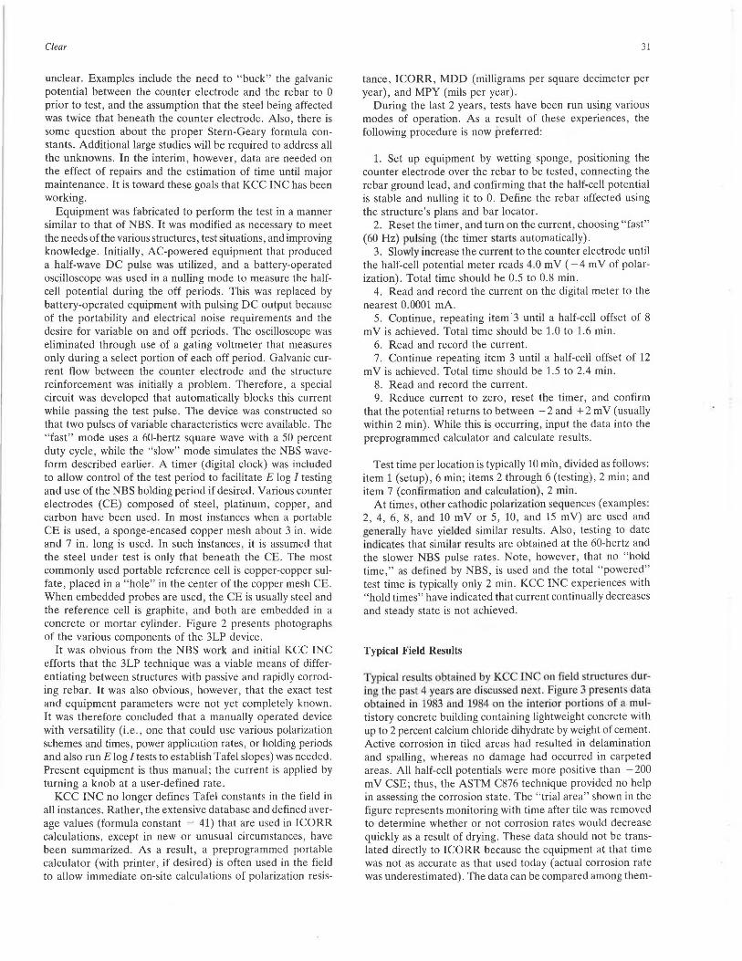
Figure 5 shows typical findings from an embedded probe in a sound area of a 45-year-old concrete chimney undergoing carbonation-induced reinforcing steel corrosion. Chloride levels were less than 0.15 percent by weight of cement. The linearity of the data (cathodic polarization vs. current) is excellent. ICORR findings from the four probes on two occa-
Clear 35
3 ELECTRODE LINEAR POLARIZATION
POTENTIAL SHIFT, -mv
0 10 20 30 36 46 55 65
TRMS CURRENT, MICRO AMPS
FIGURE 5 Potential shift vs. TRMS current.
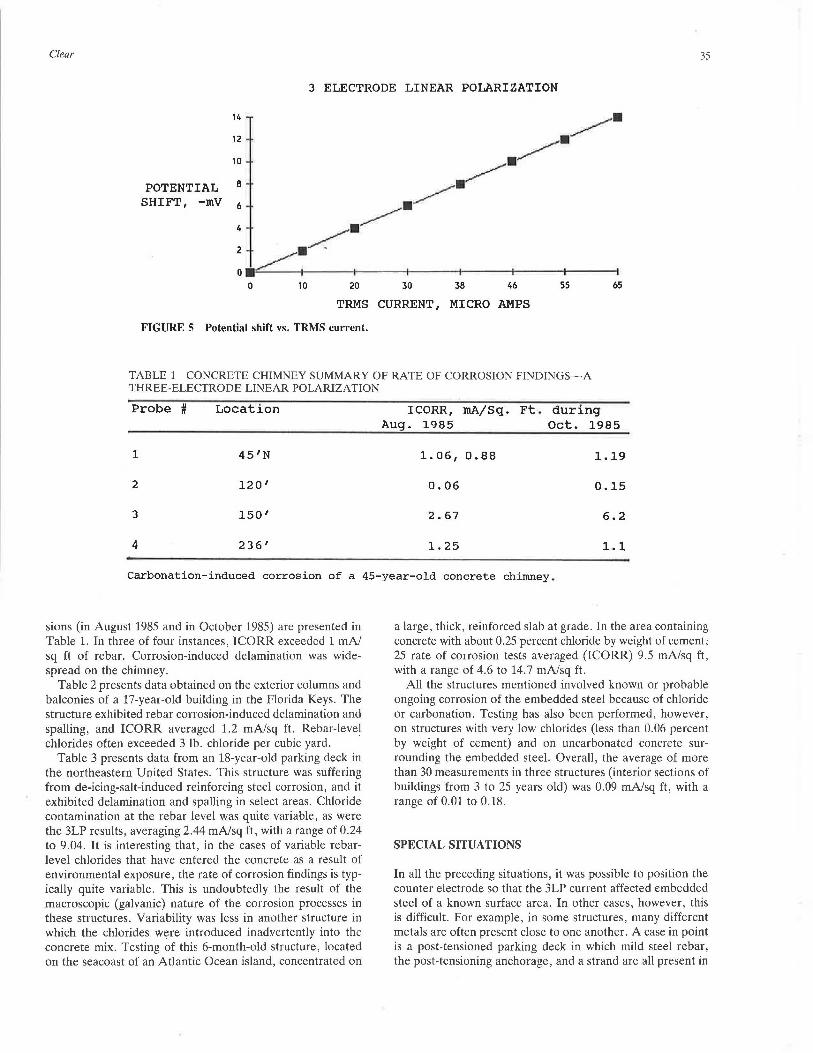
TABLE 1 CONCRETE CHIMNEY SUMMARY OF RATE OF CORROSION FINDINGS-A THREE-ELECTRODE LINEAR POLARIZATION
Probe # Location I CORR, mA/Sq. Ft. during Aug. 1985 Oct. 1985
1 45'N 1. 06, 0.88 1.19
2 120' 0.06 0.15
3 150' 2.67 6.2
4 236' 1. 25 1.1
Carbonation-induced corrosion of a 45-year-old concrete chimney.
sions (in August 1985 and in October 1985) are presented in Table 1. In three of four instances, ICORR exceeded 1 mA/ sq ft of rebar. Corrosion-induced delamination was widespread on the chimney.
Table 2 presents data obtained on the exterior columns and balconies of a 17-year-old building in the Florida Keys. The structure exhibited rebar corrosion-induced delamination and spalling, and ICORR averaged 1.2 mA/sq ft. Rebar-level chlorides often exceeded 3 lb. chloride per cubic yard.
Table 3 presents data from an 18-year-old parking deck in the northeastern United States. This structure was suffering from de-icing-salt-induced reinforcing steel corrosion, and it exhibited delamination and spalling in select areas. Chloride contamination at the rebar level was quite variable, as were the 3LP results, averaging 2.44 mA/sq ft, with a range of 0.24 to 9.04. It is interesting that, in the cases of variable rebarlevel chlorides that have entered the concrete as a result of environmental exposure, the rate of corrosion findings is typically quite variable. This is undoubtedly the result of the macroscopic (galvanic) nature of the corrosion processes in these structures. Variability was less in another structure in which the chlorides were introduced inadvertently into the concrete mix. Testing of this 6-month-old structure, located on the seacoast of an Atlantic Ocean island, concentrated on
a large, thick, reinforced slab at grade. In the area containing concrete with about 0.25 percent chloride by weight of cement, 25 rate of corrosion tests averaged (ICORR) 9.5 mA/sq ft, with a range of 4.6 to 14.7 mA/sq ft.
All the structures mentioned involved known or probable ongoing corrosion of the embedded steel because of chloride or carbonation. Testing has also been performed, however, on structures with very low chlorides (less than 0.06 percent by weight of cement) and on uncarbonated concrete surrounding the embedded steel. Overall, the average of more than 30 measurements in three structures (interior sections of buildings from 3 to 25 years old) was 0.09 mA/sq ft, with a range of 0.01 to 0.18.
SPECIAL SITUATIONS
In all the preceding situations, it was possible to position the counter electrode so that the 3LP current affected embedded steel of a known surface area. In other cases, however, this is difficult. For example, in some structures, many different metals are often present close to one another. A case in point is a post-tensioned parking deck in which mild steel rebar, the post-tensioning anchorage, and a strand are all present in
36
TABLE 2 3LP RATE OF CORROSION DATA-FLORIDA KEYS BUILDING (EXTERIOR COLUMNS AND BALCONIES)
TEST LOCATION
1-1
1-2
1-3
1-4
2-1
2-2
2-3
4-1
4-3
4-6
5-1
5-3
5-6
7-1
AVERAGE =
I CORR rnA/Sq. Ft.
1.13
2.73
1. 34
3.50
2.39
0.90
0.49
0. 46
0.20
0.04
1. 07
o. 30
1.13
0.61
1.16
RANGE= 0.04 to 3 . 50
the critical anchorage zone, where corrosion rate measurements are often wanted. The multiple-metal situation is usually approached in one of two ways.
In the first method , locations in the structure that are known to be noncorroding are defined , as well as the suspect areas that are to be tested. All areas are confirmed to have the same metal and configuration. Only !IE (the slope of the linear polarization curve) is defined at each location. Although the two Tafel slopes and the surface area of metal are unknown, it is logical to assume they are equal in all the test cases; thus, a comparison of the // E values at two locations is also a direct comparison of their corrosion rates. It is also worth noting that KCC INC has found that noncorroding steel in field structures will typically provide II E per square foot values of 0.0008 or less , whereas steel in rapidly corroding (and deteriorating) structures exhibits values as high as 0.0800. This is a 10,000 percent range; thus, even if an approximate steel surface area that is, say, 25 percent in error is defined, or the Tafel slopes vary slightly from location to location, the cor-
TRANSPORTATION RESEARCH RECORD 121 1
rosion state of the embedded metal still is established with reasonable certainty .
In the second method, small laboratory " mock-ups" are made in which the metal configuration in the structure is simulated. (If multiple metals are present, they are not permitted to contact each other and a leadwire is attached to each one separately.) They are then cast in concrete similar to that used in the structure. After curing, a counter electrode identical in size to that to be used on the structure is positioned exactly as it will be on the structure. Linear polarization tests are run normally except that data are also collected on the "current received" by each piece of metal. In some instances , identical mock-up specimens are also made, except that the concrete in one is salt-free (thus, the steel is noncorroding) and at least a portion of that in the other is salt-bearing (thus, the steel is corroding) . Through careful specimen design, a known high-corrosion-rate situation can be created. This latter approach has the advantage of defining not only current distribution but also the II E range to be expected and the values indicative of noncorroding and rapidly corroding steel.
Both the preceding techniques have been used successfully as a way of assessing the present corrosion condition of metals embedded in concrete structures.
The 3LP test cannot be performed when a cathodic protection (CP) system is "on" because the potential of the structure rebar has been polarized beyond the linear region. KCC INC has used the technique in concert with CP, however, by using embedded probes made with salty mortar and a rebar counter electrode. When the CP system is off and the rebar is depolarized, the 3LP test is run, thus allowing definition of the structure's natural corrosion rate and the effect of CP on the natural rate with time. When the CP system is on, or depolarizing, the half-cell in the probe is used to define polarization and/or depolarization; the probe rebar is used as a current pickup electrode. (This is done by connecting it to the structure rebar via a resistor and defining voltage drop across the resistor and converting it to current.)
SUMMARY AND CONCLUSIONS
Three-electrode linear polarization testing has become a valuable field tool in diagnostic and rehabilitation work on a variety of reinforced concrete field structures.
Specially constructed equipment has confirmed its ability to provide valid and useful data for projecting future distress and its rate, and for defining the effectiveness of rehabilitations. The equipment functions well both with portable probes placed on the surface and with embedded probes.
Based on KCC INC results from laboratory, outdoor exposure site, and field tests, the following guidelines for use in data interpretation (assuming constant corrosion rates with time) emerge:
ICORR less than 0.20 mA/sq ft-no corrosion damage expected
ICORR between 0.20 and 1.0 mA/sq ft-corrosion damage possible in the range of 10 to 15 years
ICORR between 1.0 and 10 mA/sq ft-corrosion damage expected in 2 to 10 years
Clear 37
TABLE 3 RATE OF CORROSION DATA-18-YEAR-OLD PARKING DECK NORTHEASTERN UNITED STATES ,
TEST I CORR LOCATION MAi::'. FT2 RPl 1.16
RP2 1. 91
RP3 1.15
RP4 2.24
RPS 0.67
RP6 4.73
RP? 0.63
RPS 1.18
RP9 8.01
RPlO 6.15
RPll 2.30
RP12 1.26
RP13 0.24
RP14 0.71
RP15 4.59
RP16 2.23
RP17 3.36
RP18 1.93
RP19 o. 72
I CORR in excess of 10 mA/sq ft-corrosion damage expected in 2 years or fewer
Deterioration rates are, of course, dependent on many other factors as well, including reinforcing steel concentration and cover.
Much remains to be learned in this area before a completely automated device and a routine, totally quantitative method become available. In the interim, however, the device and technique described here can provide excellent data for engineering decision making on field structures.
TEST I CORR LOCATION MAi::'. FT2 RP20 1.57
RP21 1.99
RP22 0.67
RP23 0.67
RP24 0.96
RP25 9.04
RP26 0.79
RP27 5. 72
RP28 0.45
RP29 2.29
RP30 2.08
RP31 1.58
RP32 2.Q9
RP33 8.06
RP34 0.45
RP36 2.13
RP37 3.86
RP38 2.42
RP39 0.57
AVERAGE 2.44
RANGE: 0.24 to 9.04
REFERENCES
1. E. Escalante, S. Ito, and M. Cohen. Measuring the Rate of Corrosion of Reinforcing Steel in Concrete. Annual Report NBSIR 80-2012. National Bureau of Standards, Gaithersburg, Md., March 1980, pp. 1-26.
2. E. Escalante, E. Whitenton, and F. Qiu. Measuring the Rate of Corrosion of Reinforcing Steel in Concrete. Final Report NBSIR 86-3456. National Bureau of Standards, Gaithersburg, Md., Oct. 1986, pp. 1-27.
Publication of this paper sponsored by Commillee on Corrosion.