Proceedings World Geothermal Congress 2010 Bali, Indonesia, 25-29 April 2010 1 Mechanical and Hydraulic Aspects of Rock-Proppant Systems: Experimental Approaches and Implications for Reservoir Treatments Reinicke, A., Zimmermann, G., Blöcher, G., Naumov, D., Stanchits, S., Dresen, G., and Huenges, E. Helmholtz Centre Potsdam, GFZ German Research Centre for Geosciences, Telegrafenberg, D14473 Potsdam, Germany E-mail address: [email protected]Keywords: Enhanced Geothermal Systems, gel-proppant treatment, fracture performance, fracture face skin ABSTRACT Reservoir stimulation technologies are standard in the hydrocarbon industry to overcome formation impairments for more than four decades (Economides and Nolte 2000). In the context of Enhanced Geothermal Systems (EGS) (Gérard et al., 2006; Calcagno and Sliaupa, 2008) the technologies are adopted to enlarge the access to the heat in the reservoir and to stimulate low permeable formations. The application of hydraulic fracturing to hydrothermal reservoirs in order to create an EGS requires a technique that is able to produce considerable higher amounts of fluids than is required for production from hydrocarbon reservoirs. A fracture - perpendicular to the direction of minimum principle stress – is created due to pumping of fluids at sufficiently high pressure through the wellbore into the formation. In general, the availability of the newly created fracture area is limited for production if no propping agent (sieved sands or ceramic spheres) is placed in the fracture to keep it open. These propping agents interact mechanically with the reservoir rock. In particular, proppant embedment and proppant crushing leads to fines production and can impair the fracture performance. In order to achieve sustainable long term productivity from a geothermal reservoir, it is indispensable to understand the hydraulic and mechanical interactions in the reservoir rock - propping agent - system. Consequently, a reservoir simulator was set up in the laboratory and different propping agents were investigated. Numerical and analytical modeling of the reservoir rock - propping agent – system identified high stress concentrations, which are responsible for the observed mechanical damaging effects. The modeling approaches highlighted mitigation strategies to attenuate proppant embedment effects, to reduce fines production and to avoid mechanically induced impairments of fracture performance. A high strength ceramic proppant type turned out to be the best candidate for the hydraulic stimulation operations in the geothermal reservoir Gross Schoenebeck, Germany. Subsequently, the hydraulic stimulations in the Lower Permian sandstones of Gross Schoenebeck reservoir were successfully performed. 1. INTRODUCTION Design of an appropriate fracture geometry as well as placement of a sufficient proppant pack of the right proppant type is a key parameter to maintain long term productivity. Proppant selection must consider hydraulic conductivity at in situ stress conditions. Hydraulic conductivity is influenced by mechanical stress on proppant pack, leading to proppant crushing and embedment as well as to a reduction of fracture width and fines production. Understanding the hydraulic and mechanical interrelations in the rock-proppant system is indispensible in order to achieve sustainable long term productivity from a reservoir. Proppant type, size and concentration have to be taken into account. Three different proppant types are dominating the market: sieved sands, intermediate strength proppants (ISP) and high strength proppants (HSP). All types are available with resin coatings. Table 1 gives an overview of proppant types and their field of application. In general, bigger proppants yield a better hydraulic conductivity but they are more sensitive for stress related problems like embedment and crushing. Smaller proppants offer less initial hydraulic conductivity, but the average hydraulic conductivity over the life cycle of the well is higher. In addition smaller proppants offer better transport properties; whereas bigger proppants can easily settle out of the gel suspension. Table 1: field of application of different proppant types proppant type manufacturing process field of application frac sands no closure stresses < 40 MPa intermediate strength proppants (ISP) fused ceramic or sintered bauxide 30 MPa < closure stress < 65 MPa high strength proppants (ISP) sintered bauxide closure stresses > 65 MPa A laboratory testing program was set up in order to investigate hydraulic-mechanical interactions in the rock- proppant system and to select the best proppant type for hydraulic stimulation operation in the production well (GtGrSk4/05) at geothermal test site Gross Schoenbeck, Germany. The fracture performance is influenced by the alteration of three different permeabilities: 1. the reservoir rock permeability; 2. the fracture / proppant pack permeability; 3. the permeability at the rock-proppant pack interface. Permeability impairment at the rock-proppant interface can affect the productivity of a reservoir significantly (Adegbola and Boney, 2002). Such flow impairment along the fracture face was investigated by Cinco-Ley and Samaniego-V. (1977) first. It is commonly referred to as fracture face skin (FFS) (figure 1). A FFS can be caused by a variety of effects like fluid-loss damage (Cinco-Ley and Samamiego-V., 1981), filter cake build-up at the fracture face (Romero et al., 2003), water blockage due to relative permeability and capillary pressure changes (Holditch, 1979) as well as liquid condensate in gas condensate reservoirs (Wang et al., 2000). Although there exists the mentioned fracture face skin models, mechanical effects have yet not been taken into account. The idea of a mechanical induced fracture face skin is explained in section 3 in detail. The different aspects that influence the generation of a mechanical FFS as well as its impact on the productivity of a reservoir are investigated by
Transcript
Proceedings World Geothermal Congress 2010 Bali, Indonesia, 25-29 April 2010
1
Mechanical and Hydraulic Aspects of Rock-Proppant Systems: Experimental Approaches and Implications for Reservoir Treatments
Reinicke, A., Zimmermann, G., Blöcher, G., Naumov, D., Stanchits, S., Dresen, G., and Huenges, E.
Helmholtz Centre Potsdam, GFZ German Research Centre for Geosciences, Telegrafenberg, D14473 Potsdam, Germany
Reservoir stimulation technologies are standard in the hydrocarbon industry to overcome formation impairments for more than four decades (Economides and Nolte 2000). In the context of Enhanced Geothermal Systems (EGS) (Gérard et al., 2006; Calcagno and Sliaupa, 2008) the technologies are adopted to enlarge the access to the heat in the reservoir and to stimulate low permeable formations. The application of hydraulic fracturing to hydrothermal reservoirs in order to create an EGS requires a technique that is able to produce considerable higher amounts of fluids than is required for production from hydrocarbon reservoirs. A fracture - perpendicular to the direction of minimum principle stress – is created due to pumping of fluids at sufficiently high pressure through the wellbore into the formation. In general, the availability of the newly created fracture area is limited for production if no propping agent (sieved sands or ceramic spheres) is placed in the fracture to keep it open. These propping agents interact mechanically with the reservoir rock. In particular, proppant embedment and proppant crushing leads to fines production and can impair the fracture performance. In order to achieve sustainable long term productivity from a geothermal reservoir, it is indispensable to understand the hydraulic and mechanical interactions in the reservoir rock - propping agent - system. Consequently, a reservoir simulator was set up in the laboratory and different propping agents were investigated. Numerical and analytical modeling of the reservoir rock - propping agent – system identified high stress concentrations, which are responsible for the observed mechanical damaging effects. The modeling approaches highlighted mitigation strategies to attenuate proppant embedment effects, to reduce fines production and to avoid mechanically induced impairments of fracture performance. A high strength ceramic proppant type turned out to be the best candidate for the hydraulic stimulation operations in the geothermal reservoir Gross Schoenebeck, Germany. Subsequently, the hydraulic stimulations in the Lower Permian sandstones of Gross Schoenebeck reservoir were successfully performed.
1. INTRODUCTION
Design of an appropriate fracture geometry as well as placement of a sufficient proppant pack of the right proppant type is a key parameter to maintain long term productivity. Proppant selection must consider hydraulic conductivity at in situ stress conditions. Hydraulic conductivity is influenced by mechanical stress on proppant pack, leading to proppant crushing and embedment as well as to a reduction of fracture width and fines production. Understanding the hydraulic and mechanical interrelations
in the rock-proppant system is indispensible in order to achieve sustainable long term productivity from a reservoir.
Proppant type, size and concentration have to be taken into account. Three different proppant types are dominating the market: sieved sands, intermediate strength proppants (ISP) and high strength proppants (HSP). All types are available with resin coatings. Table 1 gives an overview of proppant types and their field of application. In general, bigger proppants yield a better hydraulic conductivity but they are more sensitive for stress related problems like embedment and crushing. Smaller proppants offer less initial hydraulic conductivity, but the average hydraulic conductivity over the life cycle of the well is higher. In addition smaller proppants offer better transport properties; whereas bigger proppants can easily settle out of the gel suspension.
Table 1: field of application of different proppant types
proppant type manufacturing process
field of application
frac sands no closure stresses < 40 MPa
intermediate strength
proppants (ISP)
fused ceramic or sintered bauxide
30 MPa < closure stress
< 65 MPa high strength
proppants (ISP) sintered bauxide closure stresses
> 65 MPa
A laboratory testing program was set up in order to investigate hydraulic-mechanical interactions in the rock-proppant system and to select the best proppant type for hydraulic stimulation operation in the production well (GtGrSk4/05) at geothermal test site Gross Schoenbeck, Germany. The fracture performance is influenced by the alteration of three different permeabilities: 1. the reservoir rock permeability; 2. the fracture / proppant pack permeability; 3. the permeability at the rock-proppant pack interface. Permeability impairment at the rock-proppant interface can affect the productivity of a reservoir significantly (Adegbola and Boney, 2002). Such flow impairment along the fracture face was investigated by Cinco-Ley and Samaniego-V. (1977) first. It is commonly referred to as fracture face skin (FFS) (figure 1).
A FFS can be caused by a variety of effects like fluid-loss damage (Cinco-Ley and Samamiego-V., 1981), filter cake build-up at the fracture face (Romero et al., 2003), water blockage due to relative permeability and capillary pressure changes (Holditch, 1979) as well as liquid condensate in gas condensate reservoirs (Wang et al., 2000). Although there exists the mentioned fracture face skin models, mechanical effects have yet not been taken into account. The idea of a mechanical induced fracture face skin is explained in section 3 in detail. The different aspects that influence the generation of a mechanical FFS as well as its impact on the productivity of a reservoir are investigated by
Reinicke et al.
2
means of two different flow cells: The Acoustic Emission Flow Cell (AEFC) and the BiDirectional Flow Cell (BDFC). The AEFC is employed for localization of the crushing at the rock-proppant interface. The BDFC simulates the geometric flow conditions in a propped fracture and is utilized to quantify the permeability reduction at the fracture face as well as in the proppant pack.
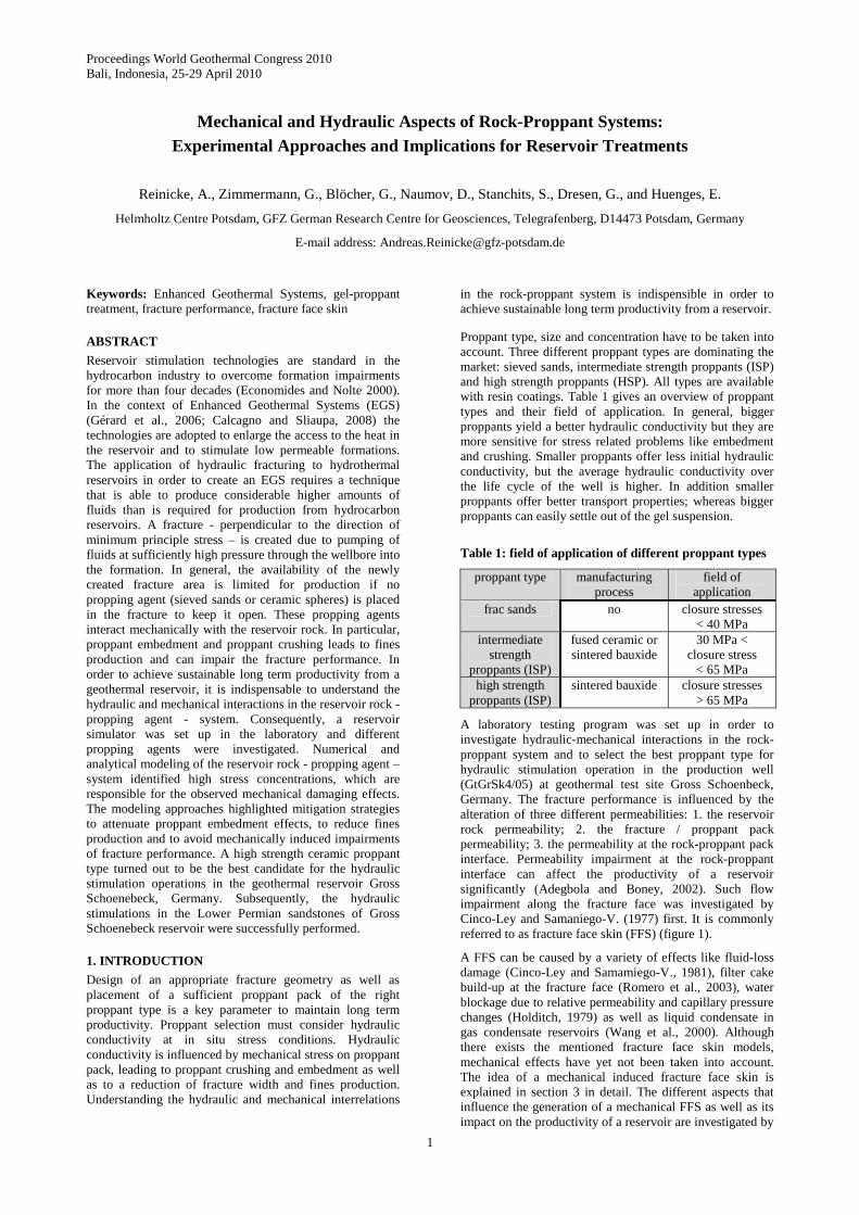
Figure 1: Flow impairment (reduced permeability) at the fracture face can affect the productivity of a reservoir. It is commonly referred to as fracture face skin (FFS) (Cinco-Ley and Samaniego-V., 1977)
Besides the empirical investigations, the destruction of proppants and rock grains is studied by means of an analytical and a numerical stress modeling approach. The analytical approach employs the theory of diametral point loading of a sphere and adopts this concept to the contacts at the rock-proppant interface. The numerical approach transfers the contact geometry from a thin section to a finite element modeling software. The arising stresses are computed from a numerical simulation of a rock-proppant interaction experiment. The observed fracture patterns in proppant filled fractures can be explained from the computed stress distributions and mitigation strategies can be derived.
2. GROSS SCHOENBECK GEOTHERMAL RESEARCH SITE
The geothermal research site Gross Schoenebeck is located in the North-East German Basin (NEGB). A doublet system consisting of a production well (GtGrSk4/05) and an injection well (EGrSk3/90) was developed (Zimmermann et al., 2007) for geothermal power generation from the Lower Permian (Rotliegend formation) as an EGS (Huenges et al., 2007). The designated pay zones are the sandstone formations as well as tight volcanic rocks. A detailed geological description is given by Norden and Förster (2006). Both wells were hydraulically stimulated to overcome fluid impairments in the vicinity of the well as well as to optimize the productivity. Zimmermann et al. (2010; this proceedings) gives a comprehensive overview over the stimulation operations in GtGrSk4/05 well.
3. MECHANICALLY INDUCED FRACTURE FACE SKIN
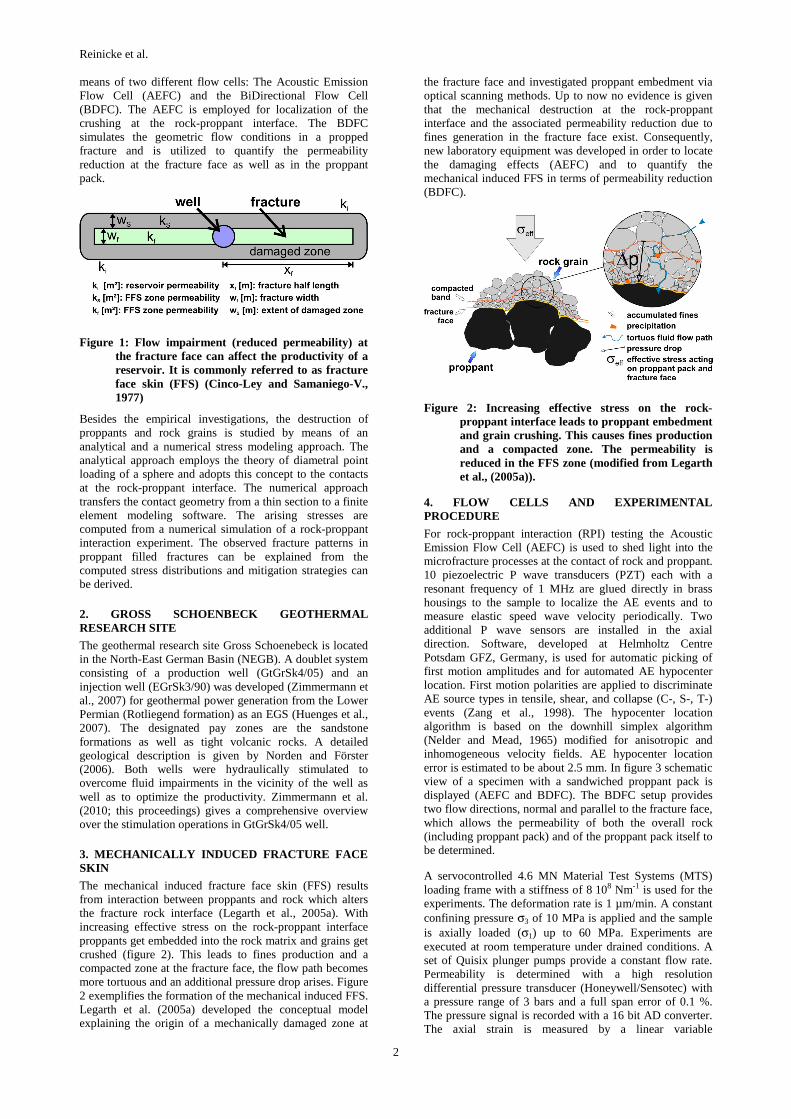
The mechanical induced fracture face skin (FFS) results from interaction between proppants and rock which alters the fracture rock interface (Legarth et al., 2005a). With increasing effective stress on the rock-proppant interface proppants get embedded into the rock matrix and grains get crushed (figure 2). This leads to fines production and a compacted zone at the fracture face, the flow path becomes more tortuous and an additional pressure drop arises. Figure 2 exemplifies the formation of the mechanical induced FFS. Legarth et al. (2005a) developed the conceptual model explaining the origin of a mechanically damaged zone at
the fracture face and investigated proppant embedment via optical scanning methods. Up to now no evidence is given that the mechanical destruction at the rock-proppant interface and the associated permeability reduction due to fines generation in the fracture face exist. Consequently, new laboratory equipment was developed in order to locate the damaging effects (AEFC) and to quantify the mechanical induced FFS in terms of permeability reduction (BDFC).
Figure 2: Increasing effective stress on the rock-proppant interface leads to proppant embedment and grain crushing. This causes fines production and a compacted zone. The permeability is reduced in the FFS zone (modified from Legarth et al., (2005a)).
4. FLOW CELLS AND EXPERIMENTAL PROCEDURE
For rock-proppant interaction (RPI) testing the Acoustic Emission Flow Cell (AEFC) is used to shed light into the microfracture processes at the contact of rock and proppant. 10 piezoelectric P wave transducers (PZT) each with a resonant frequency of 1 MHz are glued directly in brass housings to the sample to localize the AE events and to measure elastic speed wave velocity periodically. Two additional P wave sensors are installed in the axial direction. Software, developed at Helmholtz Centre Potsdam GFZ, Germany, is used for automatic picking of first motion amplitudes and for automated AE hypocenter location. First motion polarities are applied to discriminate AE source types in tensile, shear, and collapse (C-, S-, T-) events (Zang et al., 1998). The hypocenter location algorithm is based on the downhill simplex algorithm (Nelder and Mead, 1965) modified for anisotropic and inhomogeneous velocity fields. AE hypocenter location error is estimated to be about 2.5 mm. In figure 3 schematic view of a specimen with a sandwiched proppant pack is displayed (AEFC and BDFC). The BDFC setup provides two flow directions, normal and parallel to the fracture face, which allows the permeability of both the overall rock (including proppant pack) and of the proppant pack itself to be determined.
A servocontrolled 4.6 MN Material Test Systems (MTS) loading frame with a stiffness of 8 108 Nm-1 is used for the experiments. The deformation rate is 1 µm/min. A constant confining pressure σ3 of 10 MPa is applied and the sample is axially loaded (σ1) up to 60 MPa. Experiments are executed at room temperature under drained conditions. A set of Quisix plunger pumps provide a constant flow rate. Permeability is determined with a high resolution differential pressure transducer (Honeywell/Sensotec) with a pressure range of 3 bars and a full span error of 0.1 %. The pressure signal is recorded with a 16 bit AD converter. The axial strain is measured by a linear variable
Reinicke et al.
3
displacement transducer (LVDT) mounted at the end of the piston and corrected for the effective stiffness of the loading frame.
A complete test takes place in a 3 steps procedure: 1) The initial permeability of the sandstone sample, the poroelastic permeability dependence of the permeability and the Young’s modulus are determined. 2) A tensile fracture comparable to an idealized hydraulic fracture generation is created, splitting the specimen in the middle perpendicular to the core axis. 3) A copper foil sealing is fitted around the fracture, the fracture is filled with 2 lb/ft² (~ 10 kg/m²) of proppants. During test execution a constant confinement σ3 of 10 MPa is applied and the specimen is axially loaded (σ1) to simulate fracture closure. Effective stress is calculated according to
eff 1 3 Pσ =σ -σ -P (1)
where PP is the pore pressure. Loading is stopped in displacement mode at defined stress levels (σeff = 5, 20, 35, 50 MPa) and pressure drop ∆P at a constant flow Q is measured. Permeability k is calculated according to Darcy’s law (Darcy, 1856):
S
Q l µk=
∆P A (2)
where l is the sample length, µ is the dynamic viscosity of the flow medium, and AS is the cross sectional area of the sample. (The common unit for permeability is Darcy (D), which corresponds to 0.9869 10-12 m²).
The permeability of the FFS zone (kS) can be determined from the rock permeability (ki), the proppant pack permeability (kf) as well as the permeability of the rock-proppant system (kT). For that purpose the setup is approximated as a series connection of hydraulic resistors Ri, RS and Rf (compare to figure 3) resulting in following equation for the FFS zone permeability:
( )T f i S
Si f T T f i i f
k k k wk =
k k L -k k L +k w (3)
where LT is the length of the whole specimen, Li and ki are the length and permeability of the rock halves, kf and wf are permeability and width of the proppant pack and ws is the damage penetration (compare to figure 3).
The experiments are conducted with two sandstones. The first one, the Bentheim sandstone (Gildehaus quarry, Germany) is an excellent candidate to focus the investigations on the mechanical destruction at the fracture face. The Bentheim sandstone is a yellow Lower Cretaceous sandstone that contains mainly quartz; the porosity is about 22%. The second rock type, the Flechtingen sandstone (Sventesius quarry, Germany) is used to determine the influence of rock-proppant interaction on the productivity of the Gross Schoenebeck reservoir. It is a Lower Permian (Rotliegend) sandstone with a porosity about 10 %. Two kinds of proppants were tested: 1) intermediate strength ceramic proppants (ISP) with 20/40 mesh size (diameter: 0.4-0.8 mm); 2) High strength ceramic proppants (HSP) with a 20/40 mesh size.
5. EXPERIMENTAL RESULTS: PERMEABILITY ALTERATION OF THE ROCK-PROPPANT SYSTEM
Figure 4 shows the AE hypocenter locations and permeability data from Bentheim sandstone experiment with 2 lb/ft² of ISP. AE hypocenters of 5 loading steps are projected normal to the z- and the x-axis. In the first loading step confinement is applied. Only the inner part of the specimen is plotted from 40 to 80 mm. The AE events are separated in tensile, shear and compaction type (C-, S-, T-type), plotted in green, blue, and red.
The initial permeability ki at σeff of 0 MPa is about 1630 mD and shows only small variation (with regard to the error) up to maximum stress. After applying the confinement, the permeability of the rock-proppant system kt is reduced by a factor of 4 to 374 mD, up to the highest σeff of 50 MPa, a further reduction of permeability to 300 mD is observed.
The clustering of AE hypocenters in figure 4a indicates that grain crushing and proppant embedment starts at the fracture faces at low stress. No crushing events within the proppant pack can be observed.
With increasing σeff (figure 4b-e) the AE activity increases and moves from the fracture face into the proppant pack, at highest σeff the main activity is located within the proppant pack. The damage penetration wS is estimated from the thickness of AE cluster; it is about 4 mm. With increasing stress, the proportion of T-type and S-type events increase and the proportion of C-type events decreases.
Figure 5a-e shows the permeability alterations of the Flechtingen rock (ki), the fracture face skin zone (kS) and the proppant pack (kf) as function of σeff. An ISP and HSP type were tested. The initial permeability of the Rotliegend sandstone specimen ki is about 180 µD with a poroelastic permeability change of about 15 % (figure 5a). Already at low σeff = 5 MPa the permeability at the rock-proppant (ISP) interface is reduced by a factor of four (kS = 46 µD) (figure 5b). With increasing σeff the reduction increases and at σeff = 50 MPa the FFS permeability is reduced by a factor of 5.3 (kS = 31 µD). Figure 5c shows the permeability alteration of the proppant pack. The initial ISP permeability of 340 D decreases drastically to 25 % of its initial value. After unloading and opening the fracture, the ISP were obviously destroyed and a lot of fines material was blocking flow paths within the proppant pack. The permeability reduction at the rock-proppant interface is higher for the HSP (figure 5d); for maximum effective stress a reduction factor of 6.0 (kS = 28 µD) is measured. The initial HSP permeability of 400 D decreases to 50 % of its initial value (figure 5e).
6. STRESS CALCULATION: DIAMETRAL LOAD OF PROPPANTS AND QUARTZ GRAINS
An approach of Hiramatsu and Oka (1966) is employed to analyze the mechanical interaction of rock grains and proppants. For that purpose, the particles in contact are approximated as isotropic elastic spheres and a simple cubic packing of spheres is assumed. The approach Hiramatsu and Oka (1966) characterize the complete stress field within a sphere under uniaxial compression (diametral load).
Reinicke et al.
4
Figure 3: The laboratory rock-proppant interaction testing is conducted with two setups. The Acoustic Emission Flow Cell (AEFC) is equipped with 12 piezoelectric P wave transducers. It is used to identify microfracture processes at the contact of rock and proppant. The BiDirectional Flow Cell (BDFC) provides two flow directions: normal and parallel to the fracture face. The mechanically induced fracture face skin is quantified with this setup. For that purpose, the setup is approximated as a series connection of hydraulic resistors (RT = Ri + RS + Rf).
Figure 4: Permeabilities and AE hypocenters for Bentheim sandstone loaded with 2 lb/ft² of ISP are shown. Initial permeability of this specimen is about 1600 mD. The loading up to a σeff = 50 MPa leads to a significant permeability reduction (kT = 300 mD). The clustering of AE hypocenters indicates that grain crushing and proppant embedment starts at the fracture faces at small stresses. With increasing σeff the AE activity moves into the proppant pack and the proportion of tensile events increases.
Reinicke et al.
5
Figure 5: In comparison with the initial permeability of a Rotliegend sandstone specimen (ki), a reduction of permeability at the rock-proppant interface (kS) up to a factor of six is determined with the BDFC; the difference between the ISP and HSP type is small. In contrast, the permeability of the ISP pack (kf) is drastically reduced to 25 % of its initial value; the HSP permeability is reduced by 50 % at highest effective stress.
The stresses for proppant-proppant contacts (PP contact) and proppant-quartz contacts (PQ / QP contact) will be computed for four loading steps (σeff = 5, 20, 35, 50 MPa), comparable to the experiments presented in the previous section. The contact radii at the defined loading steps are calculated with the Hertzian contact theory (Hertz, 1882). For the present problem disintegration of spheres will occur in form of tensile splitting along the axis of compression if the stress overcomes tensile strength. Hence, studying of tensile stress field and its inhomogeneity along the axis of compression will deliver insights on the location and onset of crack initiation. Following mechanical parameters are used for this investigation (Shackelford and Alexander, 2000):
The stress distribution along the loading axis of a PP-contact is given in figure 6a expressed as stress severity S. The stress severity describes the stress distribution as a factor of the medium stress applied to the intersectional area of the sphere. The tensile stress is uniformly distributed over the inner part of the proppant, but approximately at position r/R = 0.9 a negative extremum of S is observed. This extremum is dependent on the contact angle Θ. Thus, S is a function of the loading force F and the effective stress. With increasing contact angle the stress severity extremum decreases and the stress becomes more uniformly distributed. For large contact angles, a tensile stress plateau over the inner 80 % of the sphere is observed. Near the surface, the stress is highly compressive.
For the given loading geometry, two failure scenarios can be derived from these observations: 1) If the contact angle is large enough, the fracture propagates from the centre. 2) If the contact angle is small, the fracture propagates from a
point near the surface at smaller load compared to case one. Once some small cracks are propagated, the strength of the loaded sphere decreases dramatically and it fails. Since the stress distribution is rotationally symmetric, a sphere can fail in fragments shaped like “orange slices”. In addition, the very high compressive stress in the contact region causes an explosive breakage and leads to a high amount of fines production. Fine fragments arise from dense crack pattern affected by high stress energy. The latter failure scenario can be found in the proppant pack (figure 7) The proppant in figure 7a is cleaved into 6 “orange slices” and the inner part is highly fragmented. The micrograph of a proppant loaded between two others (figure 7b) identifies two fractures that are initiated at the contact region and propagated towards the centre. In addition, chipping of fragments at the proppant surface is observed.
The extrema of stress severity are utilized to calculate maxima of tensile stress in quartz grains and proppants. The maximum tensile stresses σtPP, σtPQ and σtQP are plotted for the three contact cases in figure 6b. The maximum tensile stress due to PP contacts ranges from 85 MPa to 195 MPa (blue bars). The black dashed lines indicate the tensile strength interval of ISP type (244 ± 50 MPa). This interval was determined by uniaxial compression single proppant testing. The approach of Hiramatsu and Oka (1966) was utilized to calculate tensile strength of ISP from maximum compressive force loads. In the last loading stage (σeff = 50 MPa) the maximum tensile stress in the proppant is about 200 MPa and reaches the lower limit of proppant tensile strength. The maximum tensile stress in quartz grains (σtQP) increases from 32 - 80 MPa. The dashed lines in light grey define an interval for tensile strength of quartz. At σeff = 20 MPa the lower boundary is exceeded.
7. STRESS CALCULATION: IDEALISED 2D CONTACT MODEL OF QUARTZ GRAINS AND PROPPANTS
The aim of this pure mechanical elastic modeling approach with the finite element (FE) software package Rockflow/Geosys (Wang and Kolditz, 2005) is the identification of stress patterns that explain the observed fracture pattern in the proppant pack (figure 8b). In order to rebuild the grain structure as well as the shape of proppants precisely, micrographs from Bentheim sandstone and ISP are used to design an idealized 2D contact model. The number of contacts and contact radii is arranged for each proppant or quartz grain. It is impossible to take a micrograph of a proppant filled fracture for this modeling approach straightforward. In a 2D cut through a 3D packed bed of spheres, the spheres will show very few contact points. Hence, for this modeling approach the contacts between proppants and fracture faces are projected from 3D to 2D. Different contact geometries comparable to possible contact scenarios in a propped fracture are assembled. An embedded proppant (A), a three point load geometry (B & C), a very small contact area between quartz grains and proppants (B & C) as well as a very small contact area between proppants (C & E) are given in figure 8a. A special procedure is conducted in order to generate a FE-mesh from a micrograph. First step is the conversion from a redgreenblue (rgb) picture into a binary image. The boarders of grains and proppants are smoothed in this binary picture and the geometry is vectorized. An open source mesh generator gmsh (Geuzaine and Remacle, 2006) is used to create the finite element mesh. Lines of refinement and different materials (quartz grain and proppant) are defined with the gmsh tool. The mesh is fixed and not deformable. Four lines at the outer boundary apply
Reinicke et al.
6
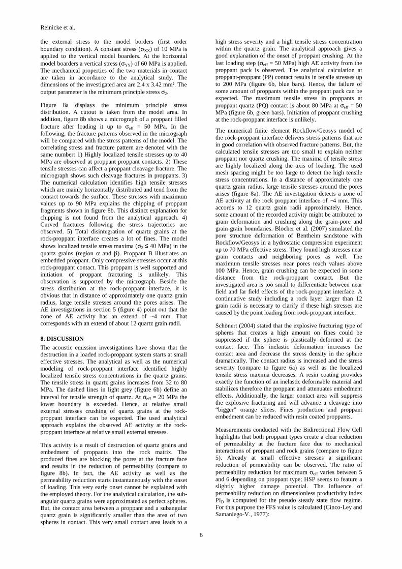
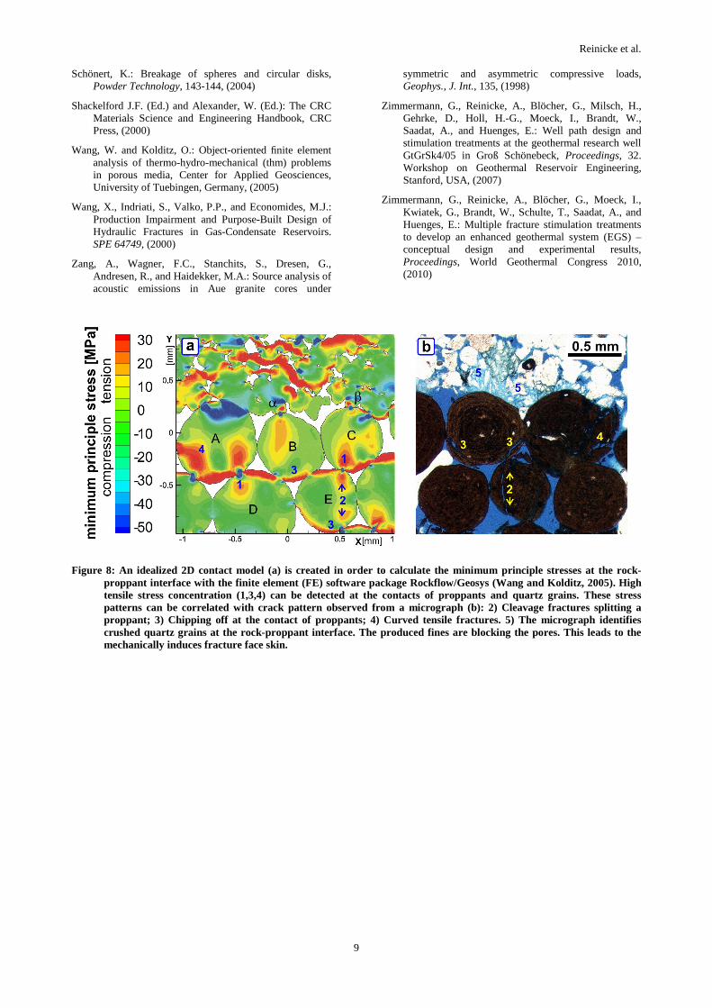
the external stress to the model borders (first order boundary condition). A constant stress (σXX) of 10 MPa is applied to the vertical model boarders. At the horizontal model boarders a vertical stress (σYY) of 60 MPa is applied. The mechanical properties of the two materials in contact are taken in accordance to the analytical study. The dimensions of the investigated area are 2.4 x 3.42 mm². The output parameter is the minimum principle stress σ2.
Figure 8a displays the minimum principle stress distribution. A cutout is taken from the model area. In addition, figure 8b shows a micrograph of a proppant filled fracture after loading it up to σeff = 50 MPa. In the following, the fracture patterns observed in the micrograph will be compared with the stress patterns of the model. The correlating stress and fracture pattern are denoted with the same number: 1) Highly localized tensile stresses up to 40 MPa are observed at proppant proppant contacts. 2) These tensile stresses can affect a proppant cleavage fracture. The micrograph shows such cleavage fractures in proppants. 3) The numerical calculation identifies high tensile stresses which are mainly horizontally distributed and tend from the contact towards the surface. These stresses with maximum values up to 90 MPa explains the chipping of proppant fragments shown in figure 8b. This distinct explanation for chipping is not found from the analytical approach. 4) Curved fractures following the stress trajectories are observed. 5) Total disintegration of quartz grains at the rock-proppant interface creates a lot of fines. The model shows localized tensile stress maxima (σ2 ≤ 40 MPa) in the quartz grains (region α and β). Proppant B illustrates an embedded proppant. Only compressive stresses occur at this rock-proppant contact. This proppant is well supported and initiation of proppant fracturing is unlikely. This observation is supported by the micrograph. Beside the stress distribution at the rock-proppant interface, it is obvious that in distance of approximately one quartz grain radius, large tensile stresses around the pores arises. The AE investigations in section 5 (figure 4) point out that the zone of AE activity has an extend of ~4 mm. That corresponds with an extend of about 12 quartz grain radii.
8. DISCUSSION
The acoustic emission investigations have shown that the destruction in a loaded rock-proppant system starts at small effective stresses. The analytical as well as the numerical modeling of rock-proppant interface identified highly localized tensile stress concentrations in the quartz grains. The tensile stress in quartz grains increases from 32 to 80 MPa. The dashed lines in light grey (figure 6b) define an interval for tensile strength of quartz. At σeff = 20 MPa the lower boundary is exceeded. Hence, at relative small external stresses crushing of quartz grains at the rock-proppant interface can be expected. The used analytical approach explains the observed AE activity at the rock-proppant interface at relative small external stresses.
This activity is a result of destruction of quartz grains and embedment of proppants into the rock matrix. The produced fines are blocking the pores at the fracture face and results in the reduction of permeability (compare to figure 8b). In fact, the AE activity as well as the permeability reduction starts instantaneously with the onset of loading. This very early onset cannot be explained with the employed theory. For the analytical calculation, the sub-angular quartz grains were approximated as perfect spheres. But, the contact area between a proppant and a subangular quartz grain is significantly smaller than the area of two spheres in contact. This very small contact area leads to a
high stress severity and a high tensile stress concentration within the quartz grain. The analytical approach gives a good explanation of the onset of proppant crushing. At the last loading step (σeff = 50 MPa) high AE activity from the proppant pack is observed. The analytical calculation at proppant-proppant (PP) contact results in tensile stresses up to 200 MPa (figure 6b, blue bars). Hence, the failure of some amount of proppants within the proppant pack can be expected. The maximum tensile stress in proppants at proppant-quartz (PQ) contact is about 80 MPa at σeff = 50 MPa (figure 6b, green bars). Initiation of proppant crushing at the rock-proppant interface is unlikely.
The numerical finite element Rockflow/Geosys model of the rock-proppant interface delivers stress patterns that are in good correlation with observed fracture patterns. But, the calculated tensile stresses are too small to explain neither proppant nor quartz crushing. The maxima of tensile stress are highly localized along the axis of loading. The used mesh spacing might be too large to detect the high tensile stress concentrations. In a distance of approximately one quartz grain radius, large tensile stresses around the pores arises (figure 8a). The AE investigation detects a zone of AE activity at the rock proppant interface of ~4 mm. This accords to 12 quartz grain radii approximately. Hence, some amount of the recorded activity might be attributed to grain deformation and crushing along the grain-pore and grain-grain boundaries. Blöcher et al. (2007) simulated the pore structure deformation of Bentheim sandstone with Rockflow/Geosys in a hydrostatic compression experiment up to 70 MPa effective stress. They found high stresses near grain contacts and neighboring pores as well. The maximum tensile stresses near pores reach values above 100 MPa. Hence, grain crushing can be expected in some distance from the rock-proppant contact. But the investigated area is too small to differentiate between near field and far field effects of the rock-proppant interface. A continuative study including a rock layer larger than 12 grain radii is necessary to clarify if these high stresses are caused by the point loading from rock-proppant interface.
Schönert (2004) stated that the explosive fracturing type of spheres that creates a high amount on fines could be suppressed if the sphere is plastically deformed at the contact face. This inelastic deformation increases the contact area and decrease the stress density in the sphere dramatically. The contact radius is increased and the stress severity (compare to figure 6a) as well as the localized tensile stress maxima decreases. A resin coating provides exactly the function of an inelastic deformable material and stabilizes therefore the proppant and attenuates embedment effects. Additionally, the larger contact area will suppress the explosive fracturing and will advance a cleavage into “bigger” orange slices. Fines production and proppant embedment can be reduced with resin coated proppants.
Measurements conducted with the Bidirectional Flow Cell highlights that both proppant types create a clear reduction of permeability at the fracture face due to mechanical interactions of proppant and rock grains (compare to figure 5). Already at small effective stresses a significant reduction of permeability can be observed. The ratio of permeability reduction for maximum σeff varies between 5 and 6 depending on proppant type; HSP seems to feature a slightly higher damage potential. The influence of permeability reduction on dimensionless productivity index PID is computed for the pseudo steady state flow regime. For this purpose the FFS value is calculated (Cinco-Ley and Samaniego-V., 1977):
Reinicke et al.
7
s iff
f s
π w ks = -1
x k
⎛ ⎞⋅⎜ ⎟⎝ ⎠ (4)
and the PID is determined from Romero et al. (2003):
D
ffD,s=0
1PI =
1+s
PI (5)
with PID,S=0 representing the dimensionless productivity index of the well with zero fracture face skin. The calculation is conducted for a fracture half length xf = 60m; this length corresponds with the fracture half length created during hydraulic stimulation in the geothermal research well EGrSk3/90 (Legarth et al., 2005b). This calculation leads to a reduction of the long term productivity of ~0.1 % (table 2). Other influences on the conductivity of fracture face and proppant pack; effects like fluid-loss damage (Cinco-Ley and Samamiego-V., 1981), filter cake build-up at the fracture face (Romero et al., 2003), water blockage due to relative permeability changes (Holditch, 1979) can lead to productivity reduction up to 90 %. This calculation makes clear that the direct influence of the mechanical induced fracture face skin is negligible compared to the listed productivity damage mechanisms.
Table 2: Reduction of long term productivity PID calculated from the measured permeability reduction at the rock-proppant interface.
ki/kS sff PID reduction
(%) 5.3±0.4 9.2 10-4 0.09
6.0±0.5 1.1 10-3 0.11
But secondary effects can be triggered due to the presence of a zone with reduced porosity at the fracture face. The reduced pore space can act as filter leading to an internal filtering of migrating fines in the reservoir fluid during production. Al-Abduwani et al. (2003) found from static internal filtration experiments with Bentheim sandstone that a suspension containing particles with a pore throat radius to particle radius ratio of 12.5 leads to considerable formation damage. A permeability reduction of 90 % of the
Bentheim cores was determined. Azarov et al. (2007) make similar results; they have modeled filter clogging affected by a suspension and stated that a ratio of 200 between effective pore size and suspension particle diameter is sufficient to clog a filter effectively. These studies highlight the impact of a reduced porosity at the fracture face. The deposit of fines transported from the reservoir rock to the fracture can cause a long term impairment of a reservoir. This hypothesis has to be proved by future laboratory experiments as well as numerical studies.
Both the HSP and the ISP have shown a clear reduction of fracture permeability due to loading the fracture up to σeff = 50 MPa. The ISP was reduced to 25 % and the HSP to 50 % of the initial values. This reduction is an effect of proppant crushing and fines generation. The pores space in the proppant pack gets blocked. The reduction of proppant pack permeability is larger than expected from the manufacturer value (up to a factor of two). This is an effect of the rough surface of the fractures faces. Platens, quite often used in standard flow cells, inhibit the generation of fines from the fracture face. A rough surface produces much more fines due to smaller contacts. These fines are transported into the proppant pack and lead to the observed permeability reduction.
9. CONCLUSIONS
The numerical modeling of the rock-proppant contact with Rockflow/Geosys identified stress patterns which are in good correlation with fracture patterns observed from micrographs of the rock-proppant interaction experiments. Analytical stress modeling predicted successfully the fracture initiation in proppants and quartz grains and identified high tensile and compressive stress concentrations. These stresses are caused by small contact areas. The disintegration of quartz grains starts at small effective stresses and result in fines production and blocking of pores at the fracture face. This leads to a mechanically induced fracture face skin (FFS) with a six-fold reduction of permeability at the fracture face. Proppant fracturing is initiated at proppant-proppant contacts at high effective stresses. Beside the tensile stress driven cleavage of proppants, the high compressive stress energy can affect an explosive type of fracturing and a high amount of fines. The explosive type of fracturing as well as the embedment of proppants can be suppressed if the sphere is plastically deformed at the contact face. A resin coating provides the function of a plastically deformable material.
Figure 6: The theory of Hiramatsu and Oka (1966) is employed for analytical stress calculation of diametral loaded spheres. Inhomogeneous stress distribution along the loading axis of two spheres (a) causes high tensile stress concentrations near the surface. These stress localizations decrease with increasing contact angle. The analytical stress calculation explains the early onset of quartz (Q) grain crushing due to high tensile stresses (green bars) at the rock-proppant interface as well as the late onset of proppant (P) crushing (blue bars).
Reinicke et al.
8
Figure 7: The proppant failure scenarios predicted from analytical stress modeling can be found in the proppant pack. The proppant in figure 7a is cleaved into 6 “orange slices” and the inner part is highly fragmented. The proppant in figure 7b shows two fractures that starts at the contact area and propagates towards the centre.
In contrast to the intermediate strength proppants (ISP), the high strength proppant (HSP) type provides a sufficient fracture conductivity even under high effective fracture closure stresses. The direct influence of the mechanically induced FFS on the productivity is negligible. Consequently, the HSP type is an excellent candidate for the hydraulic fracture stimulations in the well GtGrSk4/05. In summer 2007 the stimulation operations by use of the investigated HSP (resin coated and uncoated) were successfully conducted in the geothermal research well Gross Schoenebeck GtGrSk4/05. The productivity of the well was increased by a factor of five (Zimmermann et al., 2010; these proceedings).
ACKNOWLEDGEMENT
T. Backers as well as GeoFrames GmbH, Germany is acknowledged for supporting this work. I extend thanks to W. von Stillfried (TU Berlin, Germany) for his contributions to modeling work with Rockflow and to S. Gehrmann (Helmholtz Centre Potsdam GFZ) for preparation of samples and thin sections. Special thanks to B. Legarth (N.A.M. B.V., The Netherlands.) for introducing me to the interesting topic of formation damage and fracture face skin. This work was funded by the Helmholtz Centre Potsdam GFZ German Research Centre for Geosciences and the Federal Ministry for Environment, Nature Conservation and Nuclear Safety.
REFERENCES
Adegbola, K. and Boney, C.: Effect of Fracture Face Damage on Well productivity, SPE 73759, (2002)
Al-Abduwania, F.A.H.; Himeb, G., Alvarezb, A., and Farajzadeha, R.: New Experimental and Modelling Approach for the Quantification of Internal Filtration, SPE 94634, (2005)
Azarov, A., Radkowski D., and Baron, R.: Modeling of Filter Clogging During Suspension Filtering, Proceedings, COMSOL Conference 2007, Boston, USA, (2007)
Blöcher, G., Bruhn, D.; Zimmermann, G.; McDermott, C., and Huenges, E.: Investigation of the undrained poroelastic response of sandstones to confining pressure via laboratory experiment, numerical simulation and analytical calculation, Rock physics and geomechanics in the study of reservoirs and repositories, The Geological Society, (2007)
Calcagno P. and Sliaupa S. (Eds.): Enhanced Geothermal Innovative Network for Europe. Proceedings, Engine Final Conference, ISBN 978-2-7159-2993-7, (2008)
Charlez, P., Lemonnier, P., Ruffet, C., and Boutéca, M.J.: Thermally Induced Fracturing: Analysis of a Field Case in North Sea, SPE 36916, (1996)
Cinco-Ley, H. and Samaniego-V, F.: Effect of Wellbore Storage and Damage on the Transient Pressure Behaviour of Vertically Fractured Wells, SPE 6752, (1977)
Cinco-Ley, H. and Samaniego-V, F.: Transient pressure analysis: Finite conductivity Fracture case versus damaged fracture case. SPE 10179, (1981)
Darcy, H.: Les fontaines publiques de la ville de dijon. Dalmont, Paris., The famous Appendix - Note D, (1856)
Economides, M.J. and Nolte, K.G.: Reservoir Stimulation, 3rd Edition, Wiley and Sons Ltd., United Kingdom, (2000)
Gérard, A., A. Genter, T. Kohl, P. Lutz, P. Rose, and F. Rummel: The deep EGS (Enhanced Geothermal System) project at Soultz-sous-Forêts (Alsace, France). Geothermics, 35, (2006)
Geuzaine, C. and Remacle, J.F.: Gmsh: a three-dimensional finite element mesh generator with built-in pre- and post-processing facilities: Cleveland, OH 44106, USA, Case Western Reserve University, (2006)
Hertz, H.: Ueber die Beruehrung fester elastischer Koerper, J. Reine und Angewandte Mathematik, 92, 156, (1882)
Hiramatsu, Y. and Oka, Y.: Determination of Tensile Strength of Rock by a Compression of an Irregular Test Piece, International Journal of Rock Mechanics and Mining Sciences, 3, (1966)
Holditch, S.A.: Factors Affecting Water Blocking and Gas Flow from Hydraulically Fractured Gas Wells. JPT, (1979)
Huenges, E., Holl, H.-G., Bruhn, D., Brandt, W., Saadat, A., Moeck, I. and Zimmermann, G.: Current state of the EGS project Groß Schönebeck – drilling into the deep sedimentary geothermal reservoir, Proceedings, European Geothermal Congress, (2007)
Legarth, B., Raab, S, and Huenges, E.: Mechanical Interactions between proppants and rock and their effect on hydraulic fracture performance, DGMK-Tagungsbericht 2005-1, Fachbereich Aufsuchung und Gewinnung, (2005a)
Legarth, B., Huenges, E., and Zimmermann, G.: Hydraulic Fracturing in Sedimentary Geothermal Reservoirs, International Journal of Rock Mechanics and Mining Sciences, 42, (2005b)
Nelder, J. A. and Mead, R.: A simplex method for function minimization, Comput. J., 7, (1965)
Norden, B. and Förster, A.: Thermal conductivity and radiogenic heat production of sedimentary and magmatic rocks in the Northeast German Basin. AAPG Bulletin, 90 (6), (2006)
Romero, D.J., Valkó, P.P., and Economides, M.J.: Optimization of the Productivity Index and the Fracture Geometry of a Stimulated Well With Fracture Face and Choke Skin, SPE 81908, (2003)
Reinicke et al.
9
Schönert, K.: Breakage of spheres and circular disks, Powder Technology, 143-144, (2004)
Shackelford J.F. (Ed.) and Alexander, W. (Ed.): The CRC Materials Science and Engineering Handbook, CRC Press, (2000)
Wang, W. and Kolditz, O.: Object-oriented finite element analysis of thermo-hydro-mechanical (thm) problems in porous media, Center for Applied Geosciences, University of Tuebingen, Germany, (2005)
Wang, X., Indriati, S., Valko, P.P., and Economides, M.J.: Production Impairment and Purpose-Built Design of Hydraulic Fractures in Gas-Condensate Reservoirs. SPE 64749, (2000)
Zang, A., Wagner, F.C., Stanchits, S., Dresen, G., Andresen, R., and Haidekker, M.A.: Source analysis of acoustic emissions in Aue granite cores under
symmetric and asymmetric compressive loads, Geophys., J. Int., 135, (1998)
Zimmermann, G., Reinicke, A., Blöcher, G., Milsch, H., Gehrke, D., Holl, H.-G., Moeck, I., Brandt, W., Saadat, A., and Huenges, E.: Well path design and stimulation treatments at the geothermal research well GtGrSk4/05 in Groß Schönebeck, Proceedings, 32. Workshop on Geothermal Reservoir Engineering, Stanford, USA, (2007)
Zimmermann, G., Reinicke, A., Blöcher, G., Moeck, I., Kwiatek, G., Brandt, W., Schulte, T., Saadat, A., and Huenges, E.: Multiple fracture stimulation treatments to develop an enhanced geothermal system (EGS) – conceptual design and experimental results, Proceedings, World Geothermal Congress 2010, (2010)
Figure 8: An idealized 2D contact model (a) is created in order to calculate the minimum principle stresses at the rock-proppant interface with the finite element (FE) software package Rockflow/Geosys (Wang and Kolditz, 2005). High tensile stress concentration (1,3,4) can be detected at the contacts of proppants and quartz grains. These stress patterns can be correlated with crack pattern observed from a micrograph (b): 2) Cleavage fractures splitting a proppant; 3) Chipping off at the contact of proppants; 4) Curved tensile fractures. 5) The micrograph identifies crushed quartz grains at the rock-proppant interface. The produced fines are blocking the pores. This leads to the mechanically induces fracture face skin.