Physical CharacteristicsHousing SECC (1.2 mm) SPCC SPCCDimensions (mm) 440 x 260 x 77 mm 86.8 x 136.5 x 21 mm 86.8 x 136.5 x 21 mmWeight 5.2 kg (11.4 lbs), with one power module installed --- ---Installation --- --- ---
Number of Slots 19 slots in the front for slide-in modules, 2 slots in the back for power supply modules --- ---
Environmental LimitsOperating Temperature 0 to 60°C 0 to 60°C 0 to 60°COperating Humidity 5 to 95% RH 5 to 95% RH 5 to 95% RHStorage Temperature -20 to 75°C -20 to 75°C -20 to 75°C
Power RequirementsInput Voltage Universal 100 to 240 VAC (47 to 63 Hz) 12 VDC 12 VDC
Power Consumption 5.4 A @ 12 V (max. output) or12 to 48 VDC 150 mA @ 12 V 150 mA @ 12 V
Regulatory ApprovalsCE Class B Class BFCC Part 15 sub part B Class A Part 15 sub part B Class AEMI EN55022 1998, Class B --- ---
EMS
EN61000-4-2 (ESD), Criteria A, Level 4EN61000-4-3 (RS), Criteria A, Level 2 EN61000-4-4 (EFT), Criteria A, Level 3EN61000-4-5 (Surge), Criteria A, Level 3 EN61000-4-6 (CS), Criteria A, Level 2EN61000-4-8 (PFMF), Criteria A, Level 3EN61000-4-11 (DIPS), Criteria A
EN61000-4-2 (ESD), Criteria A, Level 4EN61000-4-3 (RS), Criteria A, Level 2EN61000-4-4 (EFT), Criteria A, Level 3EN61000-4-5 (Surge), Criteria A, Level 3EN61000-4-6 (CS), Criteria A, Level 2EN61000-4-8 (PFMF), Criteria A, Level 3
Freefall --- IEC 60068-2-32
ReliabilityWarranty 5 years (see www.moxa.com/warranty)
Industrial Networking Solutions
i n f o @ m o x a . c o m w w w. m o x a . c o m 12-3
Media Converters >
Product Selection Guides
12
Serial-to-Fiber Media Converters
ICF-1150-M-SC/STICF-1150-M-SC/ST-T
ICF-1150I-M-SC/STICF-1150I-M-SC/ST-T
ICF-1150-S-SC/STICF-1150-S-SC/ST-T
ICF-1150I-S-SC/STICF-1150I-S-SC/ST-T
TCF-142-M-SC/STTCF-142-M-SC/ST-T
TCF-142-S-SC/STTCF-142-S-SC/ST-T TCF-90-M/S
Optical Fiber SideFiber Connector SC or ST SC or ST SC or ST SC or ST SC or ST ST
Cables Requirements Single-mode: 8.3/125, 8.7/125, 9/125, or 10/125 µmMulti-mode: 50/125, 62.5/125, or 100/140 µm
Transmission Distance Single-mode: 40 kmMulti-mode: 5 km
RS-232/422/485 SideConnector --- --- --- --- Terminal Block ---RS-232 Signals TxD, RxD, SGND ---RS-422 Signals TxD+, TxD-, RxD+, RxD-, SGND ---RS-485-4w Signals TxD+, TxD-, RxD+, RxD-, SGND ---RS-485-2w Signals Data+, Data-, SGND ---Baudrate 50 bps to 921.6 Kbps ---ESD Protection 15 KV for all signals ---Isolation 2 KV RMS isolation per I/O port for 1 minute --- --- ---
Physical CharacteristicsHousing Aluminum (1 mm) ABS + PCDimensions (mm) 30.3 x 70 x 115 67 x 100 x 22 mm 42 x 80 x 22 mm
Environmental LimitsOperating Temperature 0 to 60°C or -40 to 85°C 0 to 60°COperating Humidity 5 to 95% RH 5 to 95% RHStorage Temperature -40 to 85°C -20 to 75°C
Power Requirements
Source of Input Power --- --- --- --- --- ---RS-232 port (TxD signal) or power input jack
Input Voltage 12 to 48 VDC 12 to 48 VDC 12 to 48 VDC
Power Consumption 127 mA @ 12 V 163 mA @ 12 V 140 mA @ 12 V 20 mA @ 5 V (with termination disabled)
Regulatory ApprovalsCE Class B --- --- Class BFCC Part 15 sub Class B Part 15 Subclass B Class BSafety UL 508 --- --- ---UL/CUL --- UL60950-1 ---EMI EN55022 1998, Class B EN55022 1998, Class B ---
EMS
EN61000-4-2 (ESD), Criteria A, Level 4EN61000-4-3 (RS), Criteria A, Level 3EN61000-4-4 (EFT), Criteria A, Level 4EN61000-4-5 (Surge), Criteria A, Level 3EN61000-4-6 (CS), Criteria A, Level 3EN61000-4-8 (PFMF), Criteria A, Level 5
EN61000-4-2 (ESD), Criteria A, Level 3EN61000-4-3 (RS), Criteria A, Level 2EN61000-4-4 (EFT), Criteria A, Level 2EN61000-4-5 (Surge), Criteria A, Level 3EN61000-4-6 (CS), Criteria A, Level 2EN61000-4-8 (SFMF), Criteria A, Level 1
---
ATEX Class 1, Zone 2, EEx nC IIC (pending) --- --- ---Hazardous Location UL/cUL Class 1, Div. 2, Group A, B, C and D (Pending) --- --- ---TÜV EN 60950-1 EN60950-1 ---Freefall IEC 60068-2-32 --- --- ---Water and Dust Proof IP30 --- --- ---
ReliabilityWarranty 5 years (see www.moxa.com/warranty)
w w w. m o x a . c o m i n f o @ m o x a . c o m12-4
RS-485 Data Direction Control --- --- ADDC® --- --- ---
Serial CommunicationConnectors --- --- --- --- Terminal Block on both ends DB9 male/femaleBaudrate 50 bps to 921.6 Kbps 50 bps to 921.6 Kbps 50 bps to 921.6 Kbps 50 bps to 921.6 Kbps
RS-232: TxD, RxD, RTS, CTS(Loop-back wiring: DTR to DSR and DCD)
RS-485 Data Direction Control --- --- --- --- ADDC®
Pull High Resistance150K ohm or 1K ohm (default)
Pull Low ResistanceESD Protection 15 KV 15 KV 15 KV for all signals 15 KV for all signals
Optical Isolation --- 2 KV --- 2.5 KV rms for 1 minute --- 2 KV for power and
signal 4 KV for 1 minute
Physical CharacteristicsHousing Aluminum ABS + PC Aluminum ABSDimensions (mm) 67 x 100.4 x 22 mm 42 x 80 x 22 mm 67 x 100.4 x 22 mm 42 x 80 x 23.6 mmWeight 148 ± 5 g 50 ± 5 g 148 ± 5 g 60 ± 5 g
Environmental LimitsOperating Temperature -20 to 60°C, or -40 to 85°C 0 to 60°C -20 to 60°C 0 to 60°COperating Humidity 5 to 95% RH 5 to 95% RH 5 to 95% RH 5 to 95% RHStorage Temperature -20 to 85°C -20 to 75°C -20 to 85°C -20 to 75°C
Power Requirements
Source of Input Power Power input jack RS-232 port (TxD, RTS, DTR) or power input jack RS-232 port (TxD signal) or power input jack
RS-232 port (TxD signal) or power input jack
Input Voltage 12 to 48 VDC 5 to 12 VDC 12 to 48 VDC 5 to 12 VDC
Power Consumption 300 mA @ 12 V 400 mA @ 12 V10 mA @ 5 V(with termination disabled)
20 mA @ 5 V(with termination disabled)
98 mA @ 12 V, 1.18 W 234 mA @ 12 V, 2.81 W 20 mA @ 5 V
100BaseFX Full/Half duplex selection, port break alarm maskTP port’s 10/100M, Half/Full modes, and Force/Auto modes, fi ber connection’s Full/Half mode, Link Fault Pass-Through (LFP)
Alarm Contact One relay output with current carrying capacity of 1 A @ 24 VDC One relay output with current carrying capacity of 1A @ 24 VDC --- ---
Multi-mode Transmission Distance
1000BaseSX• 0 to 500 m, 850 nm (50/125 µm, 400 MHz*km)• 0 to 275 m, 850 nm (62.5/125 µm, 200 MHz*km)
--- --- --- --- ---
1000BaseLX• 0 to 1100 m, 1310 nm (50/125 µm, 800 MHz*km)• 0 to 550 m, 1310 nm (62.5/125 µm, 500 MHz*km)
--- --- --- --- ---
Single-mode Transmission Distance
1000BaseLX 0 to 10 km, 1310 nm (9/125 µm, 3.5 PS/(nm*km)) --- ---
1000BaseLHX 0 to 40 km, 1310 nm (9/125 µm, 3.5 PS/(nm*km)) --- ---
1000BaseZX 0 to 80 km, 1550 nm (9/125 µm, 19 PS/(nm*km)) --- ---
Physical CharacteristicsHousing Metal (IP30) Metal (IP30) Plastic (IP30)Dimensions (mm) 53.6 x 135 x 105 mm 53.6 x 135 x 105 mm 25 x 109 x 97 mmWeight 630 g 630 g 125 gInstallation DIN-Rail mounting, wall mounting (with optional kit) DIN-Rail mounting
Environmental LimitsOperating Temperature 0 to 60°C or -40 to 75°C 0 to 60°COperating Humidity 5 to 95% RH 5 to 95% RHStorage Temperature -40 to 85°C -40 to 70°C
Power RequirementsInput Voltage 24 VDC (12 to 45 VDC), redundant inputs 12 to 45 VDC, 18 to 30 VAC (47-63 Hz)Input Current 0.11A (@ 24 V) 0.16A (@ 24 V) 0.15 A (@ 24 V)Connection Removable terminal block Removable 3-contact terminal blockOverload Current Protection 1.1 A 1.1 A
Hazardous Location --- UL/cUL Class1, Division 2, Groups A, B, C, and D, ATEX Class1, Zone 2, Ex nC IIC (IMC-101-M-ST, IMC-101-S-SC-80 pending) --- ---
ReliabilityWarranty 5 years (see www.moxa.com/warranty)
12-6 w w w. m o x a . c o m i n f o @ m o x a . c o m
Serial Expansion and Extension Solutions
12
Media Converters >
Introduction to the NRack System
Introduction to the NRack SystemRackmount chassis converter solutions Fiber converters have been widely used in FTTH, FTTP, and even transportation automation, power system automation, as well as many other automation systems. The main reason is because fiber optic communication has ESD immunity, wide bandwidth, zero data loss, and can transmit data over a much longer distance compared to wire cabling.
Media converters are generally used in a pair connection. That is, two media converters are used in tandem, with one converter located at the control center, and the other converter located at a remote site. This is the ideal setup from a central management point of view, in which all data is transmitted back to the control center for processing in a central computing system. For systems that require many media converters at the central site, system integrators must determine how and where to mount the converters and how to arrange power supplies.
Chassis-type media converters are a perfect choice for systems that require installing several converters in a confined space. Moxa’s NRack SystemTM is designed to help customers who are faced with the challenge of installing a high density media converter system. The NRack SystemTM saves time since less mounting is required, and the power input wiring problem is much easier to handle.
An NRack SystemTM consists of 3 major components: Rackmount Chassis, Slide-in Modules, and Power Supply Modules. Installing the power supply module in the chassis can save quite a bit of space since you do not need to deal with numerous power adaptors connecting to the various converters installed in your control center. Two main types of slide-in modules are available. One type handles data transmission only, whereas the other type is used to manage the entire chassis system.Applications
TM
TM
Thanks to optical fiber’s capability for super fast, secure data transmission, Moxa’s NRack System™ can be used to control a PTZ camera’s zoom-in/zoom-out motion. Take complete control of your building’s security system by monitoring and manipulating all of your video cameras, from a distance.
Benefi ts: Extended distance between computers and remote PTZ cameras• Zero data loss from electromagnetic interference• Simple wiring• High density solution saves space and wiring costs •
Serial-to-Fiber Converter for Surveillance Systems in Factories
SerialFiberEthernet
Industrial Networking Solutions
12-7i n f o @ m o x a . c o m w w w. m o x a . c o m
12
Media Converters >
TRC-190 Series
12
TRC-190 Series
19-inch chassis for rackmount use ›19 slots for high density applications ›Supports hot-swap and dual power input with redundancy ›Fan-less chassis design reduces repair time ›
Rackmount chassis for the NRack SystemTM
The TRC-190 series provides 19 slots for media converter modules such as the TCF-142-RM series. A TRC-190 chassis comes with one AC or DC power input, with an optional redundant power expansion
module available for greater reliability. The TRC-190 series’ power input module supports the hot-swap feature.
Introduction
Specifi cations
Physical CharacteristicsHousing: SECC (1.2 mm)Dimensions: 440 x 260 x 77 mm (18.6 x 11 x 3.3 in)Weight: 5.2 kg (11.4 lbs), with one power module installedNumber of Slots: 19 slots in the front for slide-in modules, 2 slots in the back for power supply modulesEnvironmental LimitsOperating Temperature: 0 to 60°C (32 to 140°F)Operating Humidity: 5 to 95% RHStorage Temperature: -20 to 75°C (-4 to 158°F)Power RequirementsInput Voltage: Universal 100 to 240 VAC (47 to 63 Hz) or 12 to 48 VDCPower Consumption:Max. Output: 5.4 A @ 12 V
Regulatory ApprovalsCE: Class AFCC: Part 15 sub part B Class AEMI: EN55022 2006, Class BEMS:EN61000-4-2 (ESD), Criteria A, Level 4EN61000-4-3 (RS), Criteria A, Level 2 EN61000-4-4 (EFT), Criteria A, Level 3EN61000-4-5 (Surge), Criteria A, Level 3 EN61000-4-6 (CS), Criteria A, Level 2EN61000-4-8 (PFMF), Criteria A, Level 3EN61000-4-11 (DIPS), Criteria AWarrantyWarranty Period: 5 yearsDetails: See www.moxa.com/warranty
The certifi cation logos shown here apply to some or all of the products in this section. For details, see “Regulatory Approvals” under “Specifi cations” below.
12-8
Media Converters >
Ethernet
w w w. m o x a . c o m i n f o @ m o x a . c o m
Serial Expansion and Extension Solutions
12
Dimensions
Ordering Information
Package ChecklistTRC-190 with single power input• Power cord (for TRC-190-AC • only)18 face plates• User’s Manual (printed)• Warranty Card•
260 mm (10.24 in)
440 mm
(17.34 in)484 m
m (19.07 in)
33 mm (1.3 in)
33 mm (1.3 in)
88 mm
(3.47 in)
465.6 mm
(18.34 in)
76.7 mm (3.02 in)
2.5 mm (0.1 in)
Available ModelsTRC-190-AC: Rack chassis, 2U, single 110 to 240 VAC input, with 19 slots on front panelTRC-190-DC: Rack chassis, 2U, single 12 to 48 VDC input, with 19 slots on front panel (coming soon)
Optional Accessories (can be purchased separately)PWR-190-AC: Redundant power supply, 110 to 240 VACPWR-190-DC: Redundant power supply, 12 to 48 VDC (coming soon)Plate-1: Face plate to cover unused front panel slots (required for all unused slots)
Industrial Networking Solutions
12-9i n f o @ m o x a . c o m w w w. m o x a . c o m
Media Converters >
TCF-142-RM Series
12
TCF-142-RM Series
Extend RS-232/422/485 transmission up to: ›40 km with single mode ·5 km with multi-mode ·
1K or 150K ohm adjustable pull high/low resistor ›“Ring” and “Point-to-Point” transmission supported ›
RS-232/422/485 to fi ber slide-in modules for the NRack SystemTM
The TCF-142-RM series of serial-to-fiber converters are slide-in modules that work with the TRC-190 chassis. The modules convert
The TCF-142-RM series can automatically detect the serial baudrate. This is an extremely convenient feature. Even if a device’s baudrate
from the RS-232, RS-422, or RS-485 signal to a fiber optic signal.
Introduction
Specifi cations
Automatic Baudrate Detection
is changed, the signal will still be transmitted through the media converter without any problem.
Physical CharacteristicsHousing: SPCCDimensions: 86.8 x 136.5 x 21 mm (3.42 x 5.37 x 0.83 in)Environmental LimitsOperating Temperature: 0 to 60°C (32 to 140°F)Operating Humidity: 5 to 95% RHStorage Temperature: -20 to 75°C (-4 to 158°F)Power RequirementsInput Voltage: 12 VDCPower Consumption: 150 mA @ 12 VRegulatory ApprovalsCE: Class AFCC: Part 15 sub part B Class AEMS:EN61000-4-2 (ESD), Criteria A, Level 4EN61000-4-3 (RS), Criteria A, Level 2EN61000-4-4 (EFT), Criteria A, Level 3EN61000-4-5 (Surge), Criteria A, Level 3EN61000-4-6 (CS), Criteria A, Level 2EN61000-4-8 (PFMF), Criteria A, Level 3Freefall: IEC 60068-2-32WarrantyWarranty Period: 5 yearsDetails: See www.moxa.com/warranty
The certifi cation logos shown here apply to some or all of the products in this section. For details, see “Regulatory Approvals” under “Specifi cations” below.
12-10
Media Converters >
TCF-142-RM Series
w w w. m o x a . c o m i n f o @ m o x a . c o m
Serial Expansion and Extension Solutions
12
Dimensions
TCF-142-M/S-ST Series TCF-142-M/S-SC Series
Ordering Information
Package ChecklistTCF-142 series fi ber converter• Quick Installation Guide (printed)• Warranty Card•
Available ModelsTCF-142-M-SC-RM: RS-232/422/485 to multi-mode fi ber slide-in module converter, SC connectorTCF-142-M-ST-RM: RS-232/422/485 to multi-mode fi ber slide-in module converter, ST connectorTCF-142-S-SC-RM: RS-232/422/485 to single-mode fi ber slide-in module converter, SC connectorTCF-142-S-ST-RM: RS-232/422/485 to single-mode fi ber slide-in module converter, ST connector
The certifi cation logos shown here apply to some or all of the products in this section. For details, see “Regulatory Approvals” under “Specifi cations” below.
ICF-1150 SeriesRS-232, fi ber, and RS-422/485 3-way communication ›Rotary switch to change the pull high/low resistor value ›Extend RS-232/422/485 transmission up to: ›
40 km with single-mode ·5 km with multi-mode ·
3-way Galvanic Isolation (for “I” model only) ›-40 to 85°C wide temperature models available ›Class I, Div. II certifi cation (Pending) ›
The ICF-1150 series support 2 serial ports, with a D-sub connector for RS-232 communication and a removable terminal block for RS-422 or RS-485 communication. The 3 ports (2 serial ports and one fiber port) are completely independent. When an ICF-1150 converter receives data from any one port, it will send the data out through the other 2 ports. For example, once the ICF-1150 converter receives a command
The RS-485 interface supports multi-drop or daisy-chain connections, which system engineers will use to connect serial devices such as meters, RTUs, and readers together on the same bus. Since the number of serial devices on the same bus will cause the impedance
from the remote master through the fiber port, it will convert the signal and send the command through the RS-232 and RS-422/485 ports at the same time. If the user is monitoring a system running on an RS-485 network, there is no need to use an additional RS-232 to RS-485 converter to connect the laptop computer’s serial port to the RS-485 bus.
of the data line to increase, the ICF-1150 allows users to tune the pull high/low resistor. Just rotate the switch to the appropriate value without removing the ICF-1150 from the DIN-rail.
Three-Way Communication
Rotary Switch for Setting the Pull High/Low Resistor
Rx Sensitivity:ICF-1150-S (single-mode): -25 dBmICF-1150-M (multi-mode): -20 dBmPoint-to-Point Transmission: Half-duplex or full-duplexMulti-drop Transmission: Half-duplex, fi ber ringRS-232/422/485 SideRS-232 Signals: TxD, RxD, SGNDRS-422 Signals: TxD+, TxD-, RxD+, RxD-, SGNDRS-485-4w Signals: TxD+, TxD-, RxD+, RxD-, SGNDRS-485-2w Signals: Data+, Data-, SGNDBaudrate: 50 bps to 921.6 KbpsESD Protection: 15 KV for all signalsIsolation: 2 KV RMS isolation per I/O port for 1 minute
12-12
Standalone Series >ICF-1150 Series
w w w. m o x a . c o m i n f o @ m o x a . c o m
Serial Expansion and Extension Solutions
12
Dimensions
33.41 mm
(1.32 in)48.39 m
m (1.91 in)
8.8 mm(0.35 in)
70 mm (2.76 in)
115 mm
(4.53 in)8.8 m
m
(0.35 in)
13.66 mm (0.54 in)
30.3 mm
(1.20 in)
DB9 femaleconnector
5 4 3 2 1
9 8 7 6
Physical CharacteristicsHousing: Aluminum (1 mm)Dimensions: 30.3 x 70 x 115 mm (11.9 x 27.6 x 45.3 in)Environmental LimitsOperating Temperature:Standard Models: 0 to 60°C (32 to 140°F)Wide Temp. Models: -40 to 85°C (-40 to 185°F)Operating Humidity: 5 to 95% RHStorage Temperature: -40 to 85°C (-40 to 185°F)Power RequirementsInput Voltage: 12 to 48 VDCPower Consumption:ICF-1150: 127 mA @ 12 VICF-1150I: 163 mA @ 12 VVoltage Reversal Protection: Protects against V+/V- reversalOver Current Protection: 1.1 A (protects against two signals shorted together)
Regulatory ApprovalsCE: Class BFCC: Part 15 sub Class BSafety: UL 508EMI: EN55022 2006, Class BEMS:EN61000-4-2 (ESD), Criteria A, Level 4EN61000-4-3 (RS), Criteria A, Level 2EN61000-4-4 (EFT), Criteria A, Level 4EN61000-4-5 (Surge), Criteria A, Level 3EN61000-4-6 (CS), Criteria A, Level 2EN61000-4-8 (PFMF), Criteria A, Level 3ATEX: Class 1, Zone 2, EEx nC IIC (pending)Hazardous Location: UL/cUL Class 1, Div. 2, Group A, B, C and D (Pending)Freefall: IEC 60068-2-32Water and Dust Proof: IP30WarrantyWarranty Period: 5 yearsDetails: See www.moxa.com/warranty
Package ChecklistICF-1150 series fi ber converter• Quick Installation Guide (printed)• Warranty Card•
Available ModelsICF-1150-M-SC: Industrial RS-232/422/485 to multimode fi ber converter, SC connector, 0 to 60°C operating temperatureICF-1150-M-ST: Industrial RS-232/422/485 to multimode fi ber converter, ST connector, 0 to 60°C operating temperatureICF-1150-S-SC: Industrial RS-232/422/485 to single mode fi ber converter, SC connector, 0 to 60°C operating temperatureICF-1150-S-ST: Industrial RS-232/422/485 to single mode fi ber converter, ST connector, 0 to 60°C operating temperatureICF-1150I-M-SC: Industrial RS-232/422/485 to multimode fi ber converter, SC connector, 2 KV isolation, 0 to 60°C operating temperatureICF-1150I-M-ST: Industrial RS-232/422/485 to multimode fi ber converter, ST connector, 2 KV isolation, 0 to 60°C operating temperatureICF-1150I-S-SC: Industrial RS-232/422/485 to single mode fi ber converter, SC connector, 2 KV isolation, 0 to 60°C operating temperatureICF-1150I-S-ST: Industrial RS-232/422/485 to single mode fi ber converter, ST connector, 2 KV isolation, 0 to 60°C operating temperatureICF-1150-M-SC-T: Industrial RS-232/422/485 to multimode fi ber converter, SC connector, -40 to 85°C operating temperatureICF-1150-M-ST-T: Industrial RS-232/422/485 to multimode fi ber converter, ST connector, -40 to 85°C operating temperatureICF-1150-S-SC-T: Industrial RS-232/422/485 to single mode fi ber converter, SC connector, -40 to 85°C operating temperatureICF-1150-S-ST-T: Industrial RS-232/422/485 to single mode fi ber converter, ST connector, -40 to 85°C operating temperatureICF-1150I-M-SC-T: Industrial RS-232/422/485 to multimode fi ber converter, SC connector, 2 KV isolation, -40 to 85°C operating temperatureICF-1150I-M-ST-T: Industrial RS-232/422/485 to multimode fi ber converter, ST connector, 2 KV isolation, -40 to 85°C operating temperatureICF-1150I-S-SC-T: Industrial RS-232/422/485 to single mode fi ber converter, SC connector, 2 KV isolation, -40 to 85°C operating temperatureICF-1150I-S-ST-T: Industrial RS-232/422/485 to single mode fi ber converter, ST connector, 2 KV isolation, -40 to 85°C operating temperature
Optional AccessoriesDR-4524: 45 W, 2 A Din-Rail 24 VDC power supply with universal 85 to 264 VAC input
12-14
Standalone Series >TCF-142 Series
w w w. m o x a . c o m i n f o @ m o x a . c o m
Serial Expansion and Extension Solutions
12
TCF-142 Series
“Ring” and “Point-to-Point” transmission ›Extends RS-232/422/485 transmission up to: ›
40 km with single-mode—TCF-142-S ·5 km with multi-mode—TCF-142-M ·
Compact size ›Decreases signal interference ›Protects against electrical interference and chemical corrosion ›Supports baudrates of 50 bps to 921.6 Kbps ›Wide temperature models available (-40 to 75°C) ›
RS-232/422/485 to optical fi ber media converters
The TCF-142 media converters are equipped with a multiple interface circuit that can handle RS-232 or RS-422/485 serial interfaces and multi-mode or single-mode fiber. TCF-142 converters are used to extend serial transmission up to 5 km (TCF-142-M with multi-mode
The TCF-142 converters can automatically detect the serial baudrate. This is an extremely convenient feature. Even if a device’s baudrate
The TCF-142 converters can be used to connect serial devices to a fiber ring. To form the ring, connect the Tx port of one TCF-142 to the Rx port of a neighboring converter. Once the ring is set up, simply use the DIP switches to configure the TCF-142 converters for “ring mode.” When one node transmits a signal, the signal travels around the ring until it returns back to the transmitting unit, which then blocks the signal. With the TCF-142, you can set up fiber rings that have a total circumference of up to 100 km.
fiber) or up to 40 km (TCF-142-S with single-mode fiber). The TCF-142 converters can be configured to convert either RS-232 signals, or RS-422/485 signals, but not both at the same time.
is changed, the signal will still be transmitted through the media converter without any data loss.
Introduction
Ring Operation
Automatic Baudrate Detection
Automatic Data Direction Control (ADDC®)ADDC® is a patented hardware data flow solution developed by Moxa to handle RS-485 data direction control. ADDC® senses and controls
RS-485 data direction automatically, making it unnecessary to use the hand shaking signal.
RS-232
RS-232RS-422 RS-485
TCF-142
TCF-142TCF-142
Tx
TxTx Tx
Rx
Rx RxRx
TCF-1425210TCF-142-S
sw Rx Tx
PWR
Fiber Tx
Fiber Rx
Serial to Fiber ConverterRS-232/422/485
T+ T- R+/
D+
R-/D
-
Tx Rx
GN
D
RS-422/485 RS-232 12-48V
V+
V-
5210TCF-142-S
sw Rx Tx
PWR
Fiber Tx
Fiber Rx
Serial to Fiber ConverterRS-232/422/485
T+ T- R+/
D+
R-/D
-
Tx Rx
GN
D
RS-422/485 RS-232 12-48V
V+
V-
5210TCF-142-S
sw Rx Tx
PWR
Fiber Tx
Fiber Rx
Serial to Fiber ConverterRS-232/422/485
T+ T- R+/
D+
R-/D
-
Tx Rx
GN
D
RS-422/485 RS-232 12-48V
V+
V-
5210 TCF-142-S
swRxTx
PWR
FiberTx
Fiber Rx
Serial to Fiber ConverterRS-232/422/485
T+T-R+/D
+
R-/D
-
TxRx
GN
D
RS-422/485RS-23212-48V
V+
V-
TCF-142-S-SCTCF-142-S-ST TCF-142-S-SCTCF-142-S-ST
The certifi cation logos shown here apply to some or all of the products in this section. For details, see “Regulatory Approvals” under “Specifi cations” below.
Industrial Networking Solutions
12-15
Standalone Series >TCF-142 Series
i n f o @ m o x a . c o m w w w. m o x a . c o m
12
Dimensions
TCF-142-M/S-ST
DIP Switch Settings Serial Connection SW1 SW2RS-232 ON OFFRS-422 OFF OFF
RS-485-4w OFF OFFRS-485-2w OFF ON
Built-in 120-ohm Terminator SW3Enable ONDisable OFF
Fiber Mode SW4Ring mode ON
Point-to-Point mode OFF
Specifi cations
Optical Fiber SideFiber Connector: SC or STCable Requirements:Single-mode: 8.3/125, 8.7/125, 9/125, or 10/125 µmMulti-mode: 50/125, 62.5/125, or 100/140 µmTransmission Distance:Single-mode: 40 kmMulti-mode: 5 kmWavelength:Single-mode: 1310 nmMulti-mode: 850 nmTx Output:Single-mode: > -5 dBmMulti-mode: > -5 dBmRx Sensitivity:Single-mode: -25 dBmMulti-mode: -20 dBmPoint-to-Point Transmission: Half-duplex or full-duplexRing Transmission: Half-duplexRS-232/422/485 SideConnector: Terminal BlockRS-232 Signals: Tx, Rx, GNDRS-422 Signals: TxD+, TxD-, RxD+, RxD-, GNDRS-485-4w Signals: TxD+, TxD-, RxD+, RxD-, GNDRS-485-2w Signals: Data+, Data-, GNDBaudrate: 50 bps to 921.6 KbpsESD Protection: 15 KV for all signalsPhysical CharacteristicsHousing: Aluminum (1 mm)Dimensions:Without ears: 67 x 100 x 22 mm (2.64 x 3.94 x 0.87 in)With ears: 90 x 100 x 22 mm (3.54 x 3.94 x 0.87 in)
Environmental LimitsOperating Temperature:Standard Models: 0 to 60°C (32 to 140°F)Wide Temp. Models: -40 to 75°C (-40 to 167°F)Operating Humidity: 5 to 95% RHStorage Temperature: -20 to 70°C (-4 to 167°F)Power RequirementsInput Voltage: 12 to 48 VDCPower Consumption: 140 mA @ 12 VPower Line Protection:2 KV Burst (EFT), EN61000-4-42 KV Surge, EN61000-4-5Voltage Reversal Protection: Protects against V+/V- reversalOver Current Protection: 1.1 A (protects against two signals shorted together)Regulatory ApprovalsFCC: Part 15 Subclass BUL/CUL: UL60950-1EMI: EN55022 1998, Class BEMS:EN61000-4-2 (ESD), Criteria A, Level 3EN61000-4-3 (RS), Criteria A, Level 2EN61000-4-4 (EFT), Criteria A, Level 2EN61000-4-5 (Surge), Criteria A, Level 3EN61000-4-6 (CS), Criteria A, Level 2EN61000-4-8 (SFMF), Criteria A, Level 1TÜV: EN60950-1WarrantyWarranty Period: 5 yearsDetails: See www.moxa.com/warranty
100.
4 m
m (3
.95
in)
22.0 mm(0.87 in)
21.3 mm(0.8 in)
42.3 mm (1.67 in)67 mm (2.64 in)
78 mm (3.07 in)
12.5 mm(0.49 in)
25 m
m (0
.98
in)
O 6 mm(0.24 in)
O 4 mm(0.16 in)
O 7 mm(0.28 in)
90.2 mm(3.55 in)
67 mm(2.64 in)
22.0 mm(0.87 in)
ON
1 2 3 4
12-16
Standalone Series >TCF-142 Series
w w w. m o x a . c o m i n f o @ m o x a . c o m
Serial Expansion and Extension Solutions
12TCF-142-M/S-SC
Ordering Information
Package ChecklistTCF-142 media converter• Power jack to 3-pin terminal block • adaptorQuick Installation Guide (printed)• Warranty Card•
DIP Switch Settings Serial Connection SW1 SW2RS-232 ON OFFRS-422 OFF OFF
RS-485-4w OFF OFFRS-485-2w OFF ON
Built-in 120-ohm Terminator SW3Enable ONDisable OFF
Fiber Mode SW4Ring mode ON
Point-to-Point mode OFF
Available ModelsTCF-142-M-SC: RS-232/422/485 to multi-mode optical fi ber media converter with fi ber ring support and SC connector, 0 to 60°C operating temperatureTCF-142-M-ST: RS-232/422/485 to multi-mode optical fi ber media converter with fi ber ring support and ST connector, 0 to 60°C operating temperatureTCF-142-S-SC: RS-232/422/485 to single-mode optical fi ber media converter with fi ber ring support and SC connector, 0 to 60°C operating temperatureTCF-142-S-ST: RS-232/422/485 to single-mode optical fi ber media converter with fi ber ring support and ST connector, 0 to 60°C operating temperatureTCF-142-M-SC-T: RS-232/422/485 to multi-mode optical fi ber media converter with fi ber ring support and SC connector, -40 to 75°C operating temperatureTCF-142-M-ST-T: RS-232/422/485 to multi-mode optical fi ber media converter with fi ber ring support and ST connector, -40 to 75°C operating temperatureTCF-142-S-SC-T: RS-232/422/485 to single-mode optical fi ber media converter with fi ber ring support and SC connector, -40 to 75°C operating temperatureTCF-142-S-ST-T: RS-232/422/485 to single-mode optical fi ber media converter with fi ber ring support and ST connector, -40 to 75°C operating temperature
100.
4 m
m (3
.95
in)
22.0 mm(0.87 in)
21.3 mm(0.8 in)
42.3 mm (1.67 in)67 mm (2.64 in)
78 mm (3.07 in)
12.5 mm(0.49 in)
25 m
m (0
.98
in)
O 6 mm(0.24 in)
O 4 mm(0.16 in)
O 7 mm(0.28 in)
90.2 mm(3.55 in)
67 mm(2.64 in)
22.0 mm(0.87 in)
ON
1 2 3 4
Industrial Networking Solutions
12-17
Standalone Series >TCF-90 Series
i n f o @ m o x a . c o m w w w. m o x a . c o m
12
TCF-90 Series
Use either external power or power over serial ›Extends RS-232 transmission up to: ›
40 km with single-mode—TCF-90-S ·5 km with multi-mode—TCF-90-M ·
Reduces signal interference ›Protects against electrical interference or chemical corrosion ›15 KV ESD protection for serial signals ›Baudrates up to 115.2 Kbps ›Compact size ›
Port-powered RS-232 to optical fi ber media converters
The TCF-90 is a compact media converter that transmits RS-232 signals over optical fiber. Power is derived from either the serial port or an external power source. The TCF-90 extends RS-232 transmission up to 5 km with multi-mode fiber, or up to 40 km with single-mode fiber. A pair of TCF-90 converters can be used to connect two RS-232
Connecting RS-232 devices to the TCF-90 is easy. The ST-type optical fiber connector is designed especially for data communication applications that transmit data either between or within buildings. The TCF-90 can be used for industrial applications and for applications that require secure data transfer.
The RS-232 port on the TCF-90 uses a DB9 female socket to connect directly to the host PC, with power drawn from the TxD, RTS, and DTR lines. Although the TCF-90 can obtain enough power from the three data/handshake lines whether the signal is high or low, we strongly recommend setting either the RTS or DTR signal to ON.
It’s easy enough to use a multimeter to test if the serial device is supplying the TCF-90 with enough power through the serial connection, but why bother when the TCF-90 can do the testing for you? Connect the TCF-90 to the device’s RS-232 port and set the SW4 switch to Test mode. If the port power LED indicator lights up, the TCF-90 is receiving enough power. If the LED does NOT light up, you will need to attach an external power source to the TCF-90.
In most circumstances, the TCF-90 should be able to operate without using an external power source. However, an external USB power cord or DC power supply can be used in situations where the handshake
devices with optical fiber in full duplex mode. The optical fiber isolates the data signals from dangerous increases in ground potential, ground loops, and electrical EMI/RFI noise, and enhances data security by eliminating the harmful effects of RF radiation and susceptibility to electromagnetic radiation.
Introduction
Self-powered RS-232 to Optical Fiber
LED Port Power Indicator
Optional External Power Source
lines are not available, both the RTS/DTR signals are set to OFF, or the attached device’s serial interface chip provides less power than required.
SW4
TxRx
TxRx
Fiber Optic Connection
RS-232Devices
RS-232Devices
DataTxD
5 to 12 VDC Ext. Power Adaptor
Single/Multi-modeFiber Connection
TxDData
Single/Multi-modeFiber Connection
USB Port Power Cord
The certifi cation logos shown here apply to some or all of the products in this section. For details, see “Regulatory Approvals” under “Specifi cations” below.
12-18
Standalone Series >TCF-90 Series
w w w. m o x a . c o m i n f o @ m o x a . c o m
Serial Expansion and Extension Solutions
12
Dimensions
Ordering Information
Specifi cations
PIN RS-2321 DCD2 TxD3 RxD
4 DSR
5 GND6 DTR7 CTS
8 RTS
DB9 female connector
Package ChecklistTCF-90 media converter• USB power cord (50 cm)• Quick Installation Guide• Warranty Card•
Optical Fiber SideFiber Connector: STCable Requirements:Single-mode: 8.3/125, 8.7/125, 9/125, or 10/125 µmMulti-mode: 50/125, 62.5/125, or 100/140 µmTransmission Distance:Single-mode: 40 kmMulti-mode: 5 kmWavelength:Single-mode: 1310 nmMulti-mode: 850 nmTx Output:Single-mode: > -5 dBmMulti-mode: > -5 dBmRx Sensitivity:Single-mode: -24 dBmMulti-mode: -20 dBmRS-232 SideConnector: DB9 femaleSignals:RS-232 Tx, Rx, GND (Loop-back wiring: RTS to CTS, DTR to DSR and DCD)Baudrate: 300 bps to 115.2 Kbps
Physical CharacteristicsHousing: ABS + PCDimensions: 42 x 80 x 22 mm (1.65 x 3.15 x 0.87 in)Environmental LimitsOperating Temperature: 0 to 60°C (32 to 140°F)Operating Humidity: 5 to 95% RHStorage Temperature: -20 to 75°C (-14 to 167°F)Power RequirementsSource of Input Power: RS-232 port (TxD signal) or power input jackInput Voltage: 12 to 48 VDCPower Consumption: 20 mA @ 5 V (with termination disabled)Regulatory ApprovalsCE: Class BFCC: Class BWarrantyWarranty Period: 5 yearsDetails: See www.moxa.com/warranty
Available ModelsTCF-90-M: Port-powered RS-232 to multi-mode optical fi ber converter with ST connector for 5 km transmissionTCF-90-S: Port-powered RS-232 to single-mode optical fi ber converter with ST connector for 40 km transmissionNote: Models with SC/FC connectors or a 60 km range are available by request.
Optional Accessories (can be purchased separately)Power Adaptor: See Appendix A for detailsCBL-F9M9-20: DB9 male to DB9 female RS-232 cable (20 cm)
5 4 3 2 1
9 8 7 6
22.00 mm
(0.87 in)
TestMode
SW4
Std.Mode
22.0
0 m
m (0
.87
in)
42.00 mm (1.65 in)
T +
G N
D
R +
/ D
+T
R
/ D
80.0
0 m
m (3
.15
in)
42.00 mm (1.65 in)
TEST
TxRx
Industrial Networking Solutions
12-19
Standalone Series >TCC-100/100I Series
i n f o @ m o x a . c o m w w w. m o x a . c o m
12
Dimensions
TCC-100/100I SeriesRS-232 to RS-422 conversion with RTS/CTS support ›RS-232 to 2-wire or 4-wire RS-485 conversion ›2 KV isolation protection (TCC-100I) ›Wall and DIN-rail mounting ›Plug-in terminal block for easy RS-422/485 wiring ›LED indicators for power, Tx, Rx ›-20 to 60°C operating temperature ›Wide temperature model available (-40 to 85°C ) ›
Industrial RS-232 to RS-422/485 converters with optional 2 KV isolation
The TCC-100/100I series RS-232 to RS-422/485 converters increase networking capability by extending the RS-232 transmission distance. Both converters have a superior industrial-grade design that includes
DIN-rail mounting, terminal block wiring, external terminal block for power, and optical isolation (TCC-100I and TCC-100I-T only). The TCC-100/100I series converters are ideal solutions for converting RS-232 signals to RS-422/485 in critical industrial environments.
Introduction
Ordering Information
Specifi cations
DB9 female connector PIN RS-2321 ---2 TxD3 RxD
4 ---
Package ChecklistTCC-100/100I series media converter• DK-35A: DIN-rail mounting kit• Power jack to 3-pin terminal block adaptor• Quick Installation Guide (printed)• Warranty Card•
PIN RS-2325 GND
6 ---
7 CTS
8 RTS
Available ModelsTCC-100: RS-232 to RS-422/485 converter, -20 to 60°C operating temperatureTCC-100I: RS-232 to RS-422/485 converter with optical isolation, -20 to 60°C operating temperatureTCC-100-T: RS-232 to RS-422/485 converter, -40 to 85°C operating temperatureTCC-100I-T: RS-232 to RS-422/485 converter with optical isolation, -40 to 85°C operating temperature
Serial CommunicationBaudrate: 50 bps to 921.6 KbpsESD Protection: 15 KVOptical Isolation Protection: 2 KV (TCC-100I/100I-T)Physical CharacteristicsHousing: AluminumDimensions: 67 x 100.4 x 22 mm (2.64 x 3.93 x 0.87 in)Weight: 148 ± 5 gEnvironmental LimitsOperating Temperature:Standard Models: -20 to 60°C (-4 to 140°F)Wide Temp. Models: -40 to 85°C (-40 to 185°F)Operating Humidity: 5 to 95% RHStorage Temperature: -20 to 85°C (-14 to 176°F)Power RequirementsSource of Input Power: Power input jackInput Voltage: 12 to 48 VDCPower Consumption:TCC-100/100-T: 300 mA @ 12 VTCC-100I/100I-T: 400 mA @ 12 VVoltage Reversal Protection: Protects against V+/V- reversalOver Current Protection: Protects against two signals shorted togetherRegulatory ApprovalsCE: Class BFCC: Class BWarrantyWarranty Period: 5 yearsDetails: See www.moxa.com/warranty
The certifi cation logos shown here apply to some or all of the products in this section. For details, see “Regulatory Approvals” under “Specifi cations” below.
100.
4 m
m(3
.95
in)
22.0 mm (0.87 in)
21.3mm(0.8 in)
42.3 mm(1.67 in)
78 mm (3.07 in)
12.5 mm(0.49 in)
25 m
m
(0.9
8 in
)
O 6 mm(0.24 in)
O 4 mm(0.16 in)
O 7 mm(0.28 in)
ON
1 2 3
67 mm (2.64 in) 90.2 mm (3.55 in)
22.0 mm (0.87 in)
67 mm (2.64 in)
5 4 3 2 1
9 8 7 6
12-20
Standalone Series >TCC-80/80I Series
w w w. m o x a . c o m i n f o @ m o x a . c o m
Serial Expansion and Extension Solutions
12
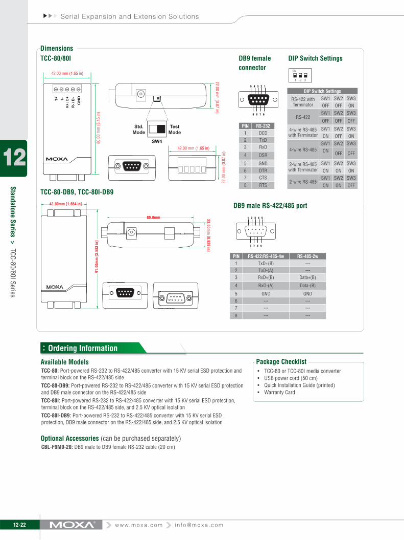
Port-powered RS-232 to RS-422/485 converter with optional 2.5 KV isolation
External power source supported but not required ›High-speed transmission up to 921.6 Kbps ›Compact size ›Converts RS-422, and both 2-wire and 4-wire RS-485 ›RS-485 automatic data direction control ›Automatic baudrate detection ›15 KV serial ESD protection ›Built-in 120-ohm termination resistors ›2.5 KV isolation (for TCC-80I only) ›LED port power indicator ›
The TCC-80/80I media converters provide complete signal conversion between RS-232 and RS-422/485, without requiring an external power source. The converters support both half duplex 2-wire RS-485 and full duplex 4-wire RS-422/485, either of which can be converted between RS-232’s TxD and RxD lines. In addition,the TCC-80/80I’s 15 KV ESD protection guards against damage from electrostatic discharge, and the TCC-80I is the world’s first high-speed, port-
The RS-232 port of the TCC-80/80I is a DB9 female socket that can connect directly to the host PC, with power drawn from the TxD line. Regardless of whether the signal is high or low, the TCC-80/80I can obtain enough power from the data line. However, external power can be used if the handshake line is not available, if the serial cable is too long, or if the RS-232 device is a low power device. For external power, a 5 to 12 VDC power supply can be connected using an adaptor or a USB power cord.
Introductionpowered converter with 2.5 KV isolation.
Automatic data direction control is provided for RS-485. In this case, the RS-485 driver is enabled automatically when the circuitry senses the TxD output from the RS-232 signal. This means that no programming effort is required to control the transmission direction of the RS-485 signal. Moreover, the TCC-80I’s patented LED port power indicator lets you check whether or not the TCC-80I is receiving enough power.
Port Power over RS-232
External Power Adaptor USB Power
TCC-80/80I Series
TxD
RTS
DTR
Long Range/ Terminated
RS-422/485 Connection
Power Adaptor
Power over TXD
RS-422/485 Devices
TxD
USB Port Power Cord
Long Range/ Terminated
RS-422/485 Connection
TxD
RTS
DTR
TCC-80-DB9 TCC-80
TCC-80ITCC-80I-DB9
The certifi cation logos shown here apply to some or all of the products in this section. For details, see “Regulatory Approvals” under “Specifi cations” below.
Industrial Networking Solutions
12-21
Standalone Series >TCC-80/80I Series
i n f o @ m o x a . c o m w w w. m o x a . c o m
12
When installing a TCC-80 or TCC-80I converter, it is important to pay attention to power consumption, RS-232 cable length, and RS-422/485 transmission distance. In general, the TCC-80 and TCC-80I obtain 50 mW of power from the power source. Standard PC COM ports can provide 70 to 90 mW of power if the TxD, RTS, and DTR
Port Power Dissipation
lines are connected. Moreover, the RS-232 cable should be shorter than 15 m (@ 9600 bps) to ensure that less power is lost from the host/device to the TCC-80. The remainder of the supplied power is used for transmitting the RS-422/485 signal.
Specifi cations
The RS-232 port of the TCC-80/80I is a DB9 female socket that can connect directly to the host PC, with power drawn from the TxD line. Electrical 2.5 KV isolation for the TCC-80I is achieved with a photo coupler that transforms the electrical signal into light, and then re-transforms the light back into an electrical signal on the other side. In this way, the two electrical circuits are completely isolated from each other. This also protects the devices from ground loop currents, reduces damage caused by data loss, and prevents damage to the communication interfaces.
It’s easy enough to test the serial device with a multimeter to determine that the serial device will provide enough power to the media converter. However, it’s even easier to let the TCC-80/80I test the device for you. Simply connect the TCC-80/80I to the device’s RS-232 port and set the SW4 switch to Test mode. If the patented port power LED indicator lights up, the TCC-80/80I is receiving enough power. If the LED does not light up, you will need to attach an external power source to the TCC-80/80I.
Port Power and Optical Isolation
LED Port Power Indicator
RS-232 SideConnector: DB9 femaleSignals:RS-232: TxD, RxD, RTS, CTS, DTR, DSR, DCD, GND(Loop-back wiring: RTS to CTS, DTR to DSR and DCD)RS-422/485 SideConnector: Terminal Block or DB9 maleSignals:(interface selected by DIP switch)RS-422: TxD+, TxD-, RxD+, RxD-, GNDRS-485-4w: TxD+, TxD-, RxD+, RxD-, GNDRS-485-2w Signals: Data+, Data-, GNDRS-485 Data Direction Control: ADDC® (automatic data direction control)Serial CommunicationBaudrate: 50 bps to 921.6 KbpsPull High Resistance: 1k ohmPull Low Resistance: 150k ohmESD Protection: 15 KVOptical Isolation: 2.5 KV rms for 1 minute (TCC-80I only)
Physical CharacteristicsHousing: ABS + PCDimensions: 42 x 80 x 22 mm (1.65 x 3.15 x 0.87 in)Weight: 50 ± 5 gEnvironmental LimitsOperating Temperature: 0 to 60°C (32 to 140°F)Operating Humidity: 5 to 95% RHStorage Temperature: -20 to 75°C (-14 to 167°F)Power RequirementsSource of Input Power: RS-232 port (TxD, RTS, DTR) or power input jackInput Voltage: 5 to 12 VDCPower Consumption:TCC-80: 10 mA @ 5 V (with termination disabled)TCC-80I: 20 mA @ 5 V (with termination disabled)Regulatory ApprovalsCE: Class BFCC: Class BWarrantyWarranty Period: 5 yearsDetails: See www.moxa.com/warranty
RS-422
SGND
232TX232DTR232RTS
DC 5~12V IN
232TX
232RX
TX TX
Control
RX
TX-I
Control-I
RX-I
2.5 KV Isolation
Test
Standard
RX
+
-
+
-
+
-
PowerIndicator DC-DC
Transceiver
Power
ADDC
232-TTL
Transceiver
RS-485-2W RS-485-4W
TxD+
TxD-
RxD+
RxD-
Data+
Data-
TxD+
TxD-
RxD+
RxD-
SGND SGND
SW4
12-22
Standalone Series >TCC-80/80I Series
w w w. m o x a . c o m i n f o @ m o x a . c o m
Serial Expansion and Extension Solutions
12
Dimensions
Ordering Information
Package ChecklistTCC-80 or TCC-80I media converter• USB power cord (50 cm)• Quick Installation Guide (printed)• Warranty Card•
Available ModelsTCC-80: Port-powered RS-232 to RS-422/485 converter with 15 KV serial ESD protection and terminal block on the RS-422/485 sideTCC-80-DB9: Port-powered RS-232 to RS-422/485 converter with 15 KV serial ESD protection and DB9 male connector on the RS-422/485 sideTCC-80I: Port-powered RS-232 to RS-422/485 converter with 15 KV serial ESD protection, terminal block on the RS-422/485 side, and 2.5 KV optical isolationTCC-80I-DB9: Port-powered RS-232 to RS-422/485 converter with 15 KV serial ESD protection, DB9 male connector on the RS-422/485 side, and 2.5 KV optical isolation
Optional Accessories (can be purchased separately)CBL-F9M9-20: DB9 male to DB9 female RS-232 cable (20 cm)
T+
22.0
0 m
m (0
.87
in)
42.00 mm (1.65 in)
80.0
0 m
m (3
.15
in)
42.00 mm (1.65 in)
T-R+
/ D+
R- /
D-
GN
DTE
ST
22.00 mm
(0.87 in)
TestMode
SW4
Std.Mode
Industrial Networking Solutions
12-23
Standalone Series >TCC-120/120I
i n f o @ m o x a . c o m w w w. m o x a . c o m
12
Dimensions
TCC-120/120IBoost serial signal to extend transmission distance ›Wall or DIN-rail mounting ›Terminal block for easy wiring ›Power input from terminal block ›DIP switch setting for built-in terminator (120 ohms) ›Boost RS-422 or RS-485 signal, or convert RS-422 to RS-485 ›2 KV isolation protection (TCC-120I) ›
Industrial RS-422/485 converter/repeater with optional 2 KV isolation
The TCC-120 and TCC-120I are RS-422/485 converters/repeaters designed to extend RS-422/485 transmission distance. Both products have a superior industrial-grade design that includes
DIN-rail mounting, terminal block wiring, and external terminal block for power. In addition, the TCC-120I supports optical isolation for system protection. The TCC-120 and TCC-120I are ideal RS-422/485 converters/repeaters for critical industrial environments.
Introduction
Ordering Information
Specifi cations
Package ChecklistTCC-120 or TCC-120I media converter• DK-35A: DIN-rail mounting kit• Quick Installation Guide (printed)• Warranty Card•
Serial CommunicationConnectors: Terminal Block on both endsBaudrate: 50 bps to 921.6 KbpsSignals:RS-422/485-4w: TxD+, TxD-, RxD+, RxD-RS-485-2w: Data+, Data-RS-485 Data Direction Control: ADDC® (automatic data direction control)ESD Protection: 15 KV for all signalsOptical Isolation: 2 KV for power and signal (TCC-120I only)Physical CharacteristicsHousing: AluminumDimensions: 67 x 100.4 x 22 mm (2.64 x 3.93 x 0.87 in)Weight: 148 ± 5 g
Environmental LimitsOperating Temperature: -20 to 60°C (-4 to 140°F)Operating Humidity: 5 to 95% RHStorage Temperature: -20 to 85°C (-14 to 176°F)Power RequirementsSource of Input Power: RS-232 port (TxD signal) or power input jackInput Voltage: 12 to 48 VDCPower Consumption:TCC-120: 98 mA @ 12 V, 1.18 WTCC-120I: 234 mA @ 12 V, 2.81 WVoltage Reversal Protection: Protects against V+/V- reversalOver Current Protection: Protects against two signals shorted togetherRegulatory ApprovalsCE: Class BFCC: Class BWarrantyWarranty Period: 5 yearsDetails: See www.moxa.com/warranty
Available ModelsTCC-120: RS-422/485 converter/repeater TCC-120I: RS-422/485 converter/repeater with 2 KV optical isolation
100.
4 m
m (
3.95
in)
22.0 mm(0.87 in)
21.3 mm(0.8in)
42.3 mm (1.67 in) 67 mm (2.64 in)78 mm (3.07 in)
12.5 mm(0.49 in)
25 m
m(0
.98
in)
O 6 mm(0.24 in)
O 4 mm(0.16 in)
O 7 mm(0.28 in)
90.2 mm (3.55 in)
22.0 mm (0.87in )
ON
1 2
ON
1 2
67 mm (2.64 in)
The certifi cation logos shown here apply to some or all of the products in this section. For details, see “Regulatory Approvals” under “Specifi cations” below.
12-24
Standalone Series >TCC-82
w w w. m o x a . c o m i n f o @ m o x a . c o m
Serial Expansion and Extension Solutions
12
TCC-82
4 channels of 4 KV RMS isolation for 1 minute ›External power source supported but not required ›15 KV serial ESD protection ›Automatic baudrate detection ›Compact size ›
Port-powered RS-232 4-channel isolator
The TCC-82 provides full electrical isolation for bi-directional serial communication between two RS-232 devices in a compact, industrial-grade package. Both sides of an RS-232 connection are isolated optically to provide perfect protection against lightning surges, accidental high voltage shorts, and ground loops. The built-in, wide range isolators are tested to ensure that they can withstand more than 4 KV rms input to output for 1 minute. This means that the TCC-82 not only meets the requirements of general serial data communications, but also the high standards required by industrial automation and medical applications. The TCC-82 protects the TxD and RxD data lines, and also protects the RTS and CTS handshake lines for a total of 4 isolated channels to provide complete protection of your RS-232 applications.
The TCC-82 supports port-powered operation, which means that it can obtain power directly from the attached serial devices. Power is obtained from the RS-232 TxD, RTS, or DTR lines, regardless of whether the signal is high or low, eliminating the need for an external power supply. However, external power can be used if handshake lines are not available, if the serial cable is too long, or if the serial device is a low powered device. For external power, the TCC-82 can use a 5 to 12 VDC adaptor or a USB power cord. Note that both sides of the connection are powered independently, so if necessary, one side can rely on port power and the other on an external power source.
When installing the TCC-82, we recommend that you connect all output signals. The TCC-82 obtains power from these signals even if they are not used by your system. Care should be taken when choosing the external power supply if your application requires the full 4 KV of isolation. Most commercial power supplies provide only 1500 VAC isolation between the primary and secondary windings. If you are using external power for both sides of the TCC-82, make sure that separate power sources are used, each with sufficient isolation protection.
Introduction
External Power Source Not Required
+5V
Isolated 5 V+5 V
DataInput
DataOutput
OpticalIsolator
Isolated 5 V
4 KV Isolation
Bi-directionalData Communication
Bi-directionalData Communication
Optional 4 KV AC IsolatedPower Source
Optional 4 KV AC IsolatedPower Source
The certifi cation logos shown here apply to some or all of the products in this section. For details, see “Regulatory Approvals” under “Specifi ca-tions” below.
Industrial Networking Solutions
12-25
Standalone Series >TCC-82
i n f o @ m o x a . c o m w w w. m o x a . c o m
12Dimensions
Ordering Information
Specifi cations
Package ChecklistTCC-82 media converter• USB power cord (50 cm) x 2• Quick Installation Guide (printed)• Warranty Card•
Available ModelsTCC-82: Port-powered RS-232 isolator with 4 KV isolation and 15 KV serial ESD protection
Optional Accessories (can be purchased separately)Power AdaptorCBL-F9M9-20: DB9 male to DB9 female RS-232 cable (20 cm)
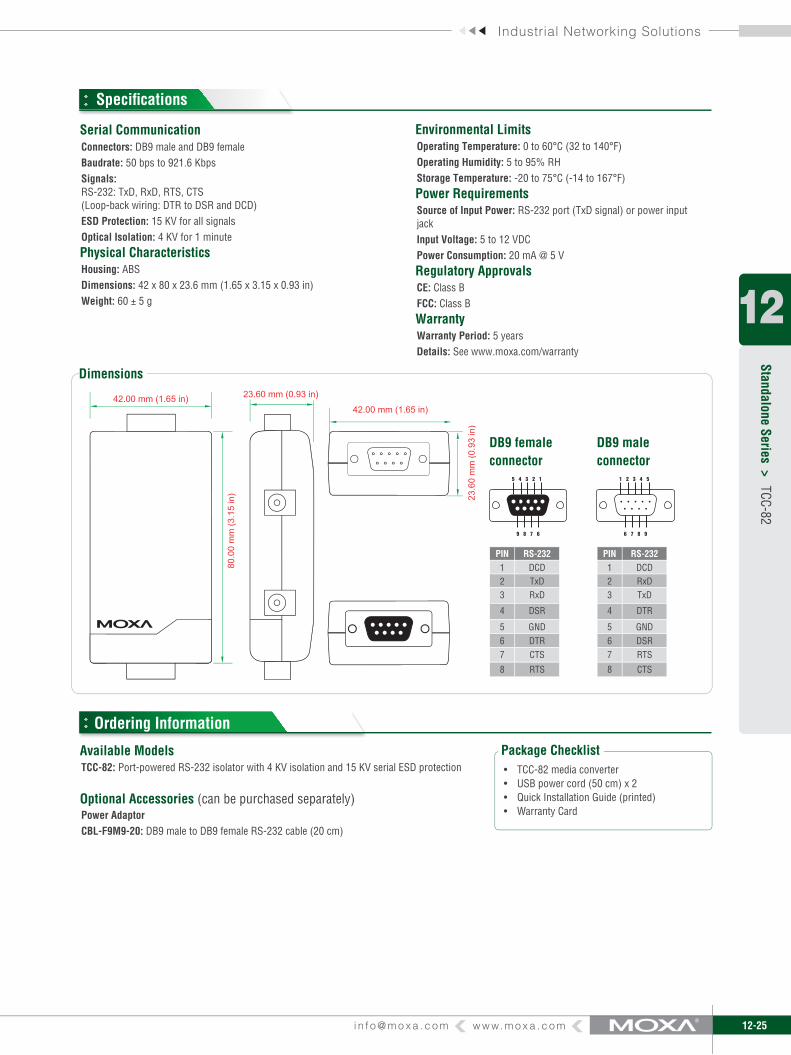
Serial CommunicationConnectors: DB9 male and DB9 femaleBaudrate: 50 bps to 921.6 KbpsSignals:RS-232: TxD, RxD, RTS, CTS(Loop-back wiring: DTR to DSR and DCD)ESD Protection: 15 KV for all signalsOptical Isolation: 4 KV for 1 minutePhysical CharacteristicsHousing: ABSDimensions: 42 x 80 x 23.6 mm (1.65 x 3.15 x 0.93 in)Weight: 60 ± 5 g
Environmental LimitsOperating Temperature: 0 to 60°C (32 to 140°F)Operating Humidity: 5 to 95% RHStorage Temperature: -20 to 75°C (-14 to 167°F)Power RequirementsSource of Input Power: RS-232 port (TxD signal) or power input jackInput Voltage: 5 to 12 VDCPower Consumption: 20 mA @ 5 VRegulatory ApprovalsCE: Class BFCC: Class BWarrantyWarranty Period: 5 yearsDetails: See www.moxa.com/warranty
PIN RS-2321 DCD2 TxD3 RxD
4 DSR
5 GND6 DTR7 CTS
8 RTS
PIN RS-2321 DCD2 RxD3 TxD
4 DTR
5 GND6 DSR7 RTS
8 CTS
DB9 femaleconnector
DB9 maleconnector
5 4 3 2 1
9 8 7 6
1 2 3 4 5
6 7 8 9
w w w. m o x a . c o m i n f o @ m o x a . c o m12-26
Serial Expansion and Extension Solutions
12
Media Converters >
IMC-101G
Industrial Gigabit Ethernet to fi ber media converter
Introduction
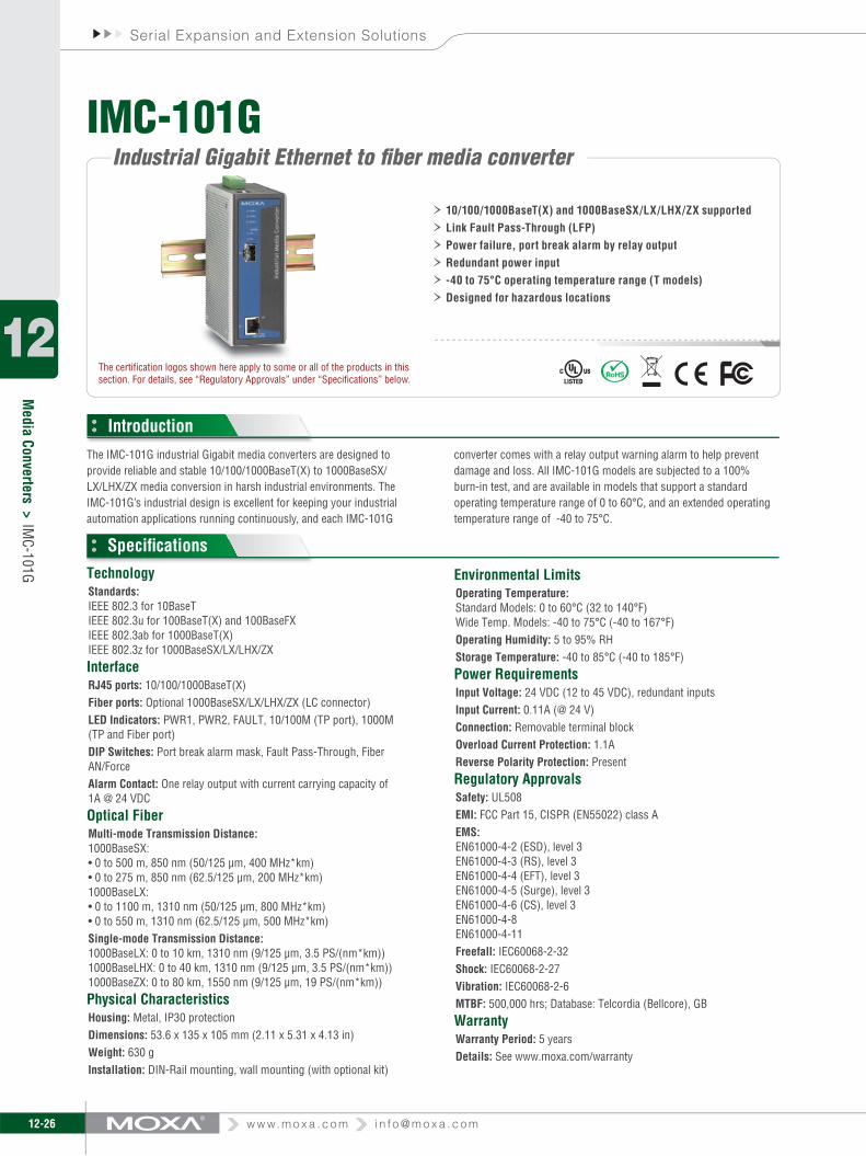
The IMC-101G industrial Gigabit media converters are designed to provide reliable and stable 10/100/1000BaseT(X) to 1000BaseSX/LX/LHX/ZX media conversion in harsh industrial environments. The IMC-101G’s industrial design is excellent for keeping your industrial automation applications running continuously, and each IMC-101G
10/100/1000BaseT(X) and 1000BaseSX/LX/LHX/ZX supported ›Link Fault Pass-Through (LFP) ›Power failure, port break alarm by relay output ›Redundant power input ›-40 to 75°C operating temperature range (T models) ›Designed for hazardous locations ›
Specifi cations
converter comes with a relay output warning alarm to help prevent damage and loss. All IMC-101G models are subjected to a 100% burn-in test, and are available in models that support a standard operating temperature range of 0 to 60°C, and an extended operating temperature range of -40 to 75°C.
TechnologyStandards:IEEE 802.3 for 10BaseTIEEE 802.3u for 100BaseT(X) and 100BaseFXIEEE 802.3ab for 1000BaseT(X)IEEE 802.3z for 1000BaseSX/LX/LHX/ZXInterfaceRJ45 ports: 10/100/1000BaseT(X)Fiber ports: Optional 1000BaseSX/LX/LHX/ZX (LC connector)LED Indicators: PWR1, PWR2, FAULT, 10/100M (TP port), 1000M (TP and Fiber port)DIP Switches: Port break alarm mask, Fault Pass-Through, Fiber AN/ForceAlarm Contact: One relay output with current carrying capacity of 1A @ 24 VDCOptical FiberMulti-mode Transmission Distance:1000BaseSX:• 0 to 500 m, 850 nm (50/125 µm, 400 MHz*km)• 0 to 275 m, 850 nm (62.5/125 µm, 200 MHz*km)1000BaseLX:• 0 to 1100 m, 1310 nm (50/125 µm, 800 MHz*km)• 0 to 550 m, 1310 nm (62.5/125 µm, 500 MHz*km)Single-mode Transmission Distance:1000BaseLX: 0 to 10 km, 1310 nm (9/125 µm, 3.5 PS/(nm*km)) 1000BaseLHX: 0 to 40 km, 1310 nm (9/125 µm, 3.5 PS/(nm*km)) 1000BaseZX: 0 to 80 km, 1550 nm (9/125 µm, 19 PS/(nm*km))Physical CharacteristicsHousing: Metal, IP30 protectionDimensions: 53.6 x 135 x 105 mm (2.11 x 5.31 x 4.13 in)Weight: 630 gInstallation: DIN-Rail mounting, wall mounting (with optional kit)
Environmental LimitsOperating Temperature:Standard Models: 0 to 60°C (32 to 140°F)Wide Temp. Models: -40 to 75°C (-40 to 167°F)Operating Humidity: 5 to 95% RHStorage Temperature: -40 to 85°C (-40 to 185°F)Power RequirementsInput Voltage: 24 VDC (12 to 45 VDC), redundant inputsInput Current: 0.11A (@ 24 V)Connection: Removable terminal blockOverload Current Protection: 1.1AReverse Polarity Protection: PresentRegulatory ApprovalsSafety: UL508EMI: FCC Part 15, CISPR (EN55022) class AEMS:EN61000-4-2 (ESD), level 3EN61000-4-3 (RS), level 3EN61000-4-4 (EFT), level 3EN61000-4-5 (Surge), level 3EN61000-4-6 (CS), level 3EN61000-4-8EN61000-4-11Freefall: IEC60068-2-32Shock: IEC60068-2-27Vibration: IEC60068-2-6MTBF: 500,000 hrs; Database: Telcordia (Bellcore), GBWarrantyWarranty Period: 5 yearsDetails: See www.moxa.com/warranty
The certifi cation logos shown here apply to some or all of the products in this section. For details, see “Regulatory Approvals” under “Specifi cations” below.
IMC-101G
Industrial Networking Solutions
i n f o @ m o x a . c o m w w w. m o x a . c o m 12-27
Media Converters >
IMC-101G
12
Dimensions
Ordering Information
5 mm ( 0.20 in)
10.65 mm (0.42 in)
10.65 mm (0.42 in)
13.1 mm (0.52 in)
15.1 mm (0.59 in)
25.4 mm (1 in)54 mm (2.13 in)
30 mm (1.18 in)
9.5 mm (0.37 in)
30.5 mm (1.20 in)
10 mm (0.39 in)
10 mm (0.39 in)
7.75 mm (0.31 in)
7.75 mm (0.31 in)
30.5 mm (1.2 in)
Ø6 mm (0.24 in)
Ø3.5 mm (0.14 in)
25.71 mm
(1.01 in
)23.15 m
m
(0.91 in)
Ø6 mm (0.24 in)
66.8 mm
(2.63 in)
48.3 mm
(1.90 in)
27.2 mm
(1.07 in
)
39.37 mm
(1.55 in)
135 mm
(5.32 in)
46.77 mm
(1.84 in)
57.05 mm
(2.25 in)
13.9 mm (0.55 in)
13 mm (0.51 in)
13 mm (0.51 in)
18 mm (0.71 in)
13.9 mm (0.55 in)
18.2 mm (0.72 in)
46 mm (1.81 in)
44mm (1.73 in)
Panel Mounting Kit Rear ViewFront ViewSide View
Available ModelsIMC-101G: Industrial 10/100/1000BaseT(X) to 1000BaseSX/LX/LHX/ZX media converter, 0 to 60°C operating temperatureIMC-101G-T: Industrial 10/100/1000BaseT(X) to 1000BaseSX/LX/LHX/ZX media converter, -40 to 75°C operating temperature
Optional Accessories (can be purchased separately)DR-4524: 45W/2A DIN-Rail 24 VDC power supply, 85 to 264 VAC inputDR-75-24: 75W/3.2A DIN-Rail 24 VDC power supply, 85 to 264 VAC inputDR-120-24: 120W/5A DIN-Rail 24 VDC power supply, 88 to 132 VAC or 176 to 264 VAC input by switchWK-46: Wall mounting kitRK-4U: 4U-high 19” rack mounting kit
w w w. m o x a . c o m i n f o @ m o x a . c o m12-28
Serial Expansion and Extension Solutions
12
Media Converters >
IMC-101 Series
Industrial 10/100BaseT(X) to 100BaseFX media converters
Introduction
The IMC-101 industrial media converters provide industrial-grade media conversion between 10/100BaseT(X) and 100BaseFX (SC/ST connectors). The IMC-101 converters’ reliable industrial design is excellent for keeping your industrial automation applications running continuously, and each IMC-101 converter comes with a relay output warning alarm to help prevent damage and loss. The IMC-101 media converters are designed for harsh industrial environments, such
as in hazardous locations (Class 1, Division 2/Zone 2, DNV, and GL Certification), and comply with FCC, TV, UL, and CE standards. The IMC-101 series is available in models that support an operating temperature from 0 to 60˚C, and an extended operating temperature from -40 to 75˚C. All IMC-101 series converters are subjected to a 100% burn-in test.
10/100BaseT(X) auto-negotiation and auto-MDI/MDI-X › Link Fault Pass-Through (LFP) › Power failure, port break alarm by relay output › Redundant power inputs ›-40 to 75°C operating temperature range (T models) › Designed for hazardous locations (Class 1 Div. 2/Zone 2) ›
a. 50/125 µm, 800 MHz*km fi ber optic cableb. 62.5/125 µm, 500 MHz*km fi ber optic cablec. 9/125 µm, 3.5 PS/(nm*km) fi ber optic cabled. 9/125 µm, 19 PS/(nm*km) fi ber optic cable
TechnologyStandards:IEEE 802.3 for 10BaseTIEEE 802.3u for 100BaseT(X) and 100BaseFXInterfaceRJ45 ports: 10/100BaseT(X)Fiber ports: 100BaseFX (SC/ST connectors)LED Indicators: PWR1, PWR2, FAULT, 10/100M (TP port), 100M (Fiber port), FDX/COL (Fiber port)DIP Switches: 100BaseFX Full/Half duplex selection, port break alarm maskAlarm Contact: One relay output with current carrying capacity of 1A @ 24 VDCOptical Fiber
Physical CharacteristicsHousing: Metal, IP30 protectionDimensions: 53.6 x 135 x 105 mm (2.11 x 5.31 x 4.13 in)Weight: 630 gInstallation: DIN-Rail mounting, wall mounting (with optional kit)Environmental LimitsOperating Temperature:Standard Models: 0 to 60°C (32 to 140°F)Wide Temp. Models: -40 to 75°C (-40 to 167°F)Operating Humidity: 5 to 95% RHStorage Temperature: -40 to 85°C (-40 to 185°F)Power RequirementsInput Voltage: 24 VDC (12 to 45 VDC), redundant inputsInput Current: 0.16A (@ 24 V)Connection: Removable terminal blockOverload Current Protection: 1.1AReverse Polarity Protection: Present
The certifi cation logos shown here apply to some or all of the products in this section. For details, see “Regulatory Approvals” under “Specifi cations” below.
IMC-101 Series
Industrial Networking Solutions
i n f o @ m o x a . c o m w w w. m o x a . c o m 12-29
Media Converters >
IMC-101 Series
12Dimensions
Ordering Information
5 mm ( 0.20 in)
10 mm (0.39 in)
10 mm (0.39 in)
46 mm (1.81 in)
66.8 mm
(2.63 in)
57.05 mm
(2.25 in)
13.9 mm (0.55 in)
13.9 mm (0.55 in)
18.2 mm (0.72 in)
Ø6 mm (0.24 in)
Ø3.5 mm (0.14 in)
Ø6 mm (0.24 in)
13.1 mm (0.52 in)
15.1 mm (0.59 in)
25.4 mm (1 in)
135 mm
(5.32 in)
54 mm (2.13 in)
30 mm (1.18 in)
9.5 mm (0.37 in) 25.71 mm
(1.01 in
)23.15 m
m
(0.91 in)
39.37 mm
(1.55 in)
46.77 mm
(1.84 in)
10.65 mm (0.42 in)
10.65 mm (0.42 in)
30.5 mm (1.20 in)
13 mm (0.51 in)
13 mm (0.51 in)
18 mm (0.71 in)
44mm (1.73 in)
48.3 mm
(1.90 in)
27.2 mm
(1.07 in
)
7.75 mm (0.31 in)
7.75 mm (0.31 in)
30.5 mm (1.2 in)
Panel Mounting Kit Rear ViewFront ViewSide View
Regulatory ApprovalsSafety: UL508, UL60950-1, CSA C22.2 No. 60950-1, EN60950-1EMI: FCC Part 15, CISPR (EN55022) class AEMS:EN61000-4-2 (ESD), level 3EN61000-4-3 (RS), level 3EN61000-4-4 (EFT), level 3EN61000-4-5 (Surge), level 3EN61000-4-6 (CS), level 3EN61000-4-8EN61000-4-11Hazardous Location: UL/cUL Class1, Division 2, Groups A, B, C, and D, ATEX Class1, Zone 2, Ex nC IIC (IMC-101-M-ST, IMC-101-S-SC-80 pending)Freefall: IEC60068-2-32
Available ModelsIMC-101-M-SC: Industrial 10/100BaseT(X) to 100BaseFX media converter, multi mode, SC connector, 0 to 60°C operating temperatureIMC-101-M-ST: Industrial 10/100BaseT(X) to 100BaseFX media converter, multi mode, ST connector, 0 to 60°C operating temperatureIMC-101-S-SC: Industrial 10/100BaseT(X) to 100BaseFX media converter, single mode, SC connector, 40 km, 0 to 60°C operating temperatureIMC-101-S-SC-80: Industrial 10/100BaseT(X) to 100BaseFX media converter, single mode, SC connector, 80 km, 0 to 60°C operating temperatureIMC-101-M-SC-T: Industrial 10/100BaseT(X) to 100BaseFX media converter, multi mode, SC connector, -40 to 75°C operating temperatureIMC-101-M-ST-T: Industrial 10/100BaseT(X) to 100BaseFX media converter, multi mode, ST connector, -40 to 75°C operating temperatureIMC-101-S-SC-T: Industrial 10/100BaseT(X) to 100BaseFX media converter, single mode, SC connector, 40 km, -40 to 75°C operating temperatureIMC-101-S-SC-80-T: Industrial 10/100BaseT(X) to 100BaseFX media converter, single mode, SC connector, 80 km, -40 to 75°C operating temperature
Optional Accessories (can be purchased separately)DR-4524: 45W/2A DIN-Rail 24 VDC power supply, 85 to 264 VAC inputDR-75-24: 75W/3.2A DIN-Rail 24 VDC power supply, 85 to 264 VAC inputDR-120-24: 120W/5A DIN-Rail 24 VDC power supply, 88 to 132 VAC/176 to 264 VAC input by switchWK-46: Wall mounting kitRK-4U: 4U-high 19” rack mounting kitSC to ST, SC to SC, ST to ST Connectors: See page A-11 for details
w w w. m o x a . c o m i n f o @ m o x a . c o m12-30
Serial Expansion and Extension Solutions
12
Media Converters >
IMC-21 Series
TechnologyStandards:IEEE 802.3 for 10BaseTIEEE 802.3u for 100BaseT(X) and 100BaseFXIEEE 802.3x for Flow ControlInterfaceRJ45 ports: 10/100BaseT(X)Fiber ports: 100BaseFX (SC/ST connectors)LED Indicators: Power, 10/100M (TP port), 100M (fi ber port), FDX/COL (fi ber port)DIP Switches: TP port’s 10/100M, Half/Full modes, and Force/Auto modes, fi ber connection’s Full/Half mode, Link Fault Pass-Through (LFP)Optical Fiber
Physical CharacteristicsHousing: Plastic, IP30 protectionDimensions: 25 x 109 x 97 mm (0.98 x 4.29 x 3.82 in)Weight: 125 gInstallation: DIN-Rail mountingEnvironmental LimitsOperating Temperature:Standard Models: 0 to 60°C (32 to 140°F)Wide Temp. Models: -40 to 75°C (-40 to 167°F)Operating Humidity: 5 to 95% RHStorage Temperature: -40 to 70°C (-40 to 158°F)Power RequirementsInput Voltage: 12 to 45 VDC, 18 to 30 VAC (47-63 Hz)Input Current: 0.15A (@ 24 V)Connection: Removable 3-contact terminal blockOverload Current Protection: 1.1 AReverse Polarity Protection: Present
Entry-level industrial 10/100BaseT(X) to 100BaseFX media converters
Introduction
The IMC-21 industrial media converters are entry-level 10/100BaseT(X) to 100BaseFX media converters designed to provide reliable and stable operation in harsh industrial environments. The converters are a cost-effective solution that run on either a 12 to 45 VDC power input or 18 to 30 VAC power input, and can operate
reliably in temperatures ranging from -10 to 60°C. The rugged hardware design ensures that your Ethernet equipment can withstand demanding industrial conditions. The IMC-21 converters are easy to mount on a DIN-Rail or in distribution boxes.
Multi-mode or single-mode, with SC or ST fi ber connector ›Link Fault Pass-Through (LFP) ›Power inputs: 12 to 45 VDC, 18 to 30 VAC (47-63 Hz) ›-10 to 60°C operating temperature range ›DIP switches to select FDX/HDX/10/100/Auto/Force ›
Specifi cations
100BaseFX
Multi-mode Single-mode
Distance 5 km, 1300 nm 40 km, 1310 nmMax. TX Output -14 dBm 0 dBm
Min. TX Output -20 dBm -5 dBm
RX Sensitivity -34 to -30 dBm -36 to -32 dBm
The certifi cation logos shown here apply to some or all of the products in this section. For details, see “Regulatory Approvals” under “Specifi cations” below.
IMC-21 Series
Industrial Networking Solutions
i n f o @ m o x a . c o m w w w. m o x a . c o m 12-31
Available ModelsIMC-21-M-SC: Industrial 10/100BaseT(X) to 100BaseFX media converter, multi mode, SC connectorIMC-21-M-ST: Industrial 10/100BaseT(X) to 100BaseFX media converter, multi mode, ST connectorIMC-21-S-SC: Industrial 10/100BaseT(X) to 100BaseFX media converter, single mode, SC connector
Optional Accessories (can be purchased separately)RK-4U: 4U-high 19” rack mounting kitSC to ST, SC to SC, ST to ST Connectors: See page A-11 for details