25
| Date post: | 17-Feb-2019 |
| Category: |
Documents |
| Upload: | vuongnguyet |
| View: | 219 times |
| Download: | 0 times |


ETA-Danmark A/S Kollegievej 6 DK-2920 Charlottenlund Tel. +45 72 24 59 00 Fax +45 72 24 59 04 Internet www.etadanmark.dk
MEMBER OF EOTA
Authorised and n otified according to Article 10 o f the Council Directive 89/106/EEC of 21 December 1988 on the approximation of laws, regulations and a dministrative provisions o f Member States relating to construction products
European Technical Approval ETA-11/0344
Trade name: BOSSONG BCR EPOXY 21
Holder of approval: BOSSONG SPA Via Enrico Fermi 51 IT-24050 Grassobbio (Bg) Tel. +39 035 3846 011 Fax +39 035 3846 012 Internet www.bossong.com
Generic type and use of con-struction product:
Bonded anchor with anchor rod made of galvanized steel or stainless steel of sizes M8, M10, M12, M16, M20, M24, M27 and M30 for use in concrete
Valid f rom: to:
2011-09-15 2016-09-15
Manufacturing plant: BOSSONG SPA Via Enrico Fermi 51 IT-24050 Grassobbio (Bg)
This European Technical Approval contains:
24 pages including 16 annexes which form an integral part of the document

Page 2 of 24 pages of European Technical Approval no. ETA-11/0344
I LEGAL BASIS AND GENERAL CONDITIONS
1 This European Technical Approval is issued by ETA-Danmark A/S in accordance with:
- Council Directive 89/106/EEC of 21 December 1988 on the approximation of laws, regulations and administrative provisions of Member States relating to construction products1, as amended by Council Directive 93/68/EEC of 22 July 19932.
- Bekendtgørelse 559 af 27-06-1994 (afløser bekendtgørelse 480 af 25-06-1991) om ikrafttræden af EF direktiv af 21. december 1988 om indbyrdes tilnærmelse af medlemsstaternes love og administrative bestemmelser om byggevarer.
- Common Procedural Rules for Requesting, Preparing and the Granting of European Technical Approvals set out in the Annex to Commission Decision 94/23/EC3.
- ETAG 001 - Guideline for European Technical Approval of metal anchors for use in concrete
– Part 5: Bonded anchors
2 ETA-Danmark A/S is authorized to check whether the provisions of this European Technical Approval are met. Checking may take place in the manufacturing plant. Nevertheless, the responsibility for the conformity of the products to the European Technical Approval and for their fitness for the intended use remains with the holder of the European Technical Approval.
3 This European Technical Approval is not to be transferred to manufacturers or agents of manu-facturers other than those indicated on page 1, or manufacturing plants other than those indicated on page 1 of this European Technical Approval.
1 Official Journal of the European Communities No L40, 11 Feb 1989, p 12.
2 Official Journal of the European Communities No L220, 30 Aug 1993, p 1.
3 Official Journal of the European Communities No L 17, 20 Jan 1994, p 34.
4 This European Technical Approval may be withdrawn by ETA-Danmark A/S pursuant to Article 5(1) of Council Directive89/106/EEC.
5 Reproduction of this European Technical Approval including transmission by electronic means shall be in full. However, partial reproduction can be made with the written consent of ETA-Danmark A/S. In this case partial reproduction has to be designated as such. Texts and drawings of advertising brochures shall not contradict or misuse the European Technical Approval.
6 This European Technical Approval is issued by ETA-Danmark A/S in English.
This version corresponds fully to the version circulated within EOTA. Translations into other languages have to be designated as such.

Page 4 of 24 pages of European Technical Approval no. ETA-11/0344
2 Characteristics o f product and assessment
2.1 Characteristics of productThe anchor in the range of M8 to M30 and the mortar cartridges corresponds to t he d rawings given in t he Annex 1 to 4 . The characteristic material v alues, dimensions and tolerances of the anchors not indicated in Annexes shall correspond to the respective values laid down in the technical documentation4 of this European Technical Approval.
The characteristic a nchor values f or t he d esign of anchorages are given in Annexes 12 to 16.
Each m ortar cartridge i s marked w ith the identifying mark o f the producer a nd w ith the trade name. The threaded r od a re e ither delivered w ith the mortar cartridges or c ommercial standard t hreaded r ods purchased separately.
The BOSSONG BCR E poxy i njection m ortar is delivered in mortar cartridges in a size of 265 ml, 400 ml and 900 ml in accordance with Annex 4.
2.2 Methods of verification The assessment of fitness of the anchor for the intended use in r elation to t he r equirements for mechanical resistance and stability and safety in use in the sense of the Essential Requirements 1 and 4 has been made in accordance with the « Guideline for European Technical Approval of Metal Anchors for use in Concrete », Part 1 « Anchors in general » and Part 5 « Bonded anchors », on the basis of Option 1 and 7.
In addition to the specific clauses relating to dangerous substances c ontained i n this E uropean technical approval, there may be other requirements applicable to the products f alling w ithin its scope (e.g. transposed European legislation and national laws, regulations and administrative p rovisions). !n o rder t o meet t he provisions of the Construction Products Directive, these requirements need also to be complied with, when and where they apply.
4 The technical documentation o f this European Technical Approval is deposited at ETA-Danmark and, as far as relevant for the tasks of t he a pproved bodies involved i n the attestation of conformity procedure, is handed over to the approved bodies

Page 6 of 24 pages of European Technical Approval no. ETA-11/0344
The results of p roduct c ertification and continuous surveillance shall be made available on demand by the certification body or i nspection body, respectively, to ETA-Danmark. I n cases w here t he p rovisions of t he European Technical Approval and the control plan are no l onger fulfilled t he c onformity certificate shall be withdrawn.
3.3 CE marking
The CE marking shall be affixed on each packaging of anchors and/or injection mortar cartridge. The symbol « CE » s hall b e accompanied by the following information: -i dentification number of the certification body; -n ame or identifying mark of the - producer and
manufacturing plant; -t he last two digits of the year in which the CE-
marking was affixed; -n umber of the EC certificate of conformity; -N o. of ETA Guideline -n umber of the European Technical Approval; -u se category (ETAG 001-1 option 1 or 7) -s ize

Page 8 of 24 pages of European Technical Approval no. ETA-11/0344
4.2.3 Responsibility of the manufacturer
It is the manufacturer's responsibility to ensure that the information on the specific conditions according to 1 and 2 including Annexes referred to in 4.2.1. and 4.2.2. is given to those who are concerned. This information may be made by reproduction of the respective parts of the European T echnical A pproval. I n addition a ll installation data shall be shown clearly on the package and/or on an enclosed instruction sheet, preferably using illustration(s).
The minimum data required are: -d rill bit diameter, -t hreaded rod diameter, -m inimum installation depth -m aximum thickness of the fixture, -r equired torque moment, -a dmissible service temperature range, -l oading (curing) time of the bonding material
depending on the installation temperature, -i nformation on the installation procedure,
including cleaning of the hole, preferably by means of an illustration,
-r eference to any special installation equipment needed,
-i dentification of the manufacturing batch.
All data shall be presented in a clear and explicit form.
5 Recommendations on packaging, transport and storage
The mortar cartridges shall be protected against sun radiation and shall be stored according to the manufacturer's instructions in dry conditions at temperatures of at least +5°C to not more than +30°C.
Mortar cartridges with expired shelf life must no longer be used.
Thomas Bruun Manager, ETA-Danmark
Page 9 of 24 pages of European Technical Approval no. ETA-11/0344
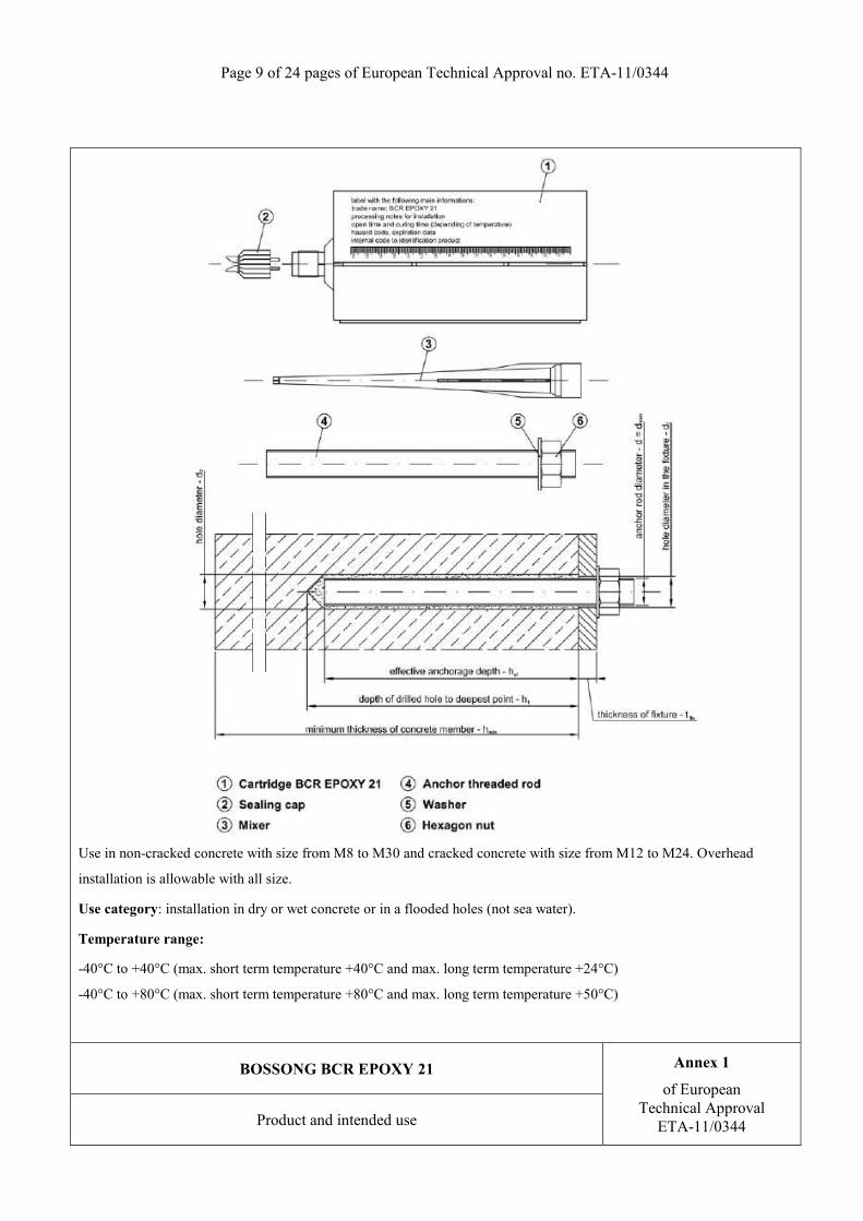
Use in non-cracked concrete with size from M8 to M30 and cracked concrete with size from M12 to M24. Overhead
installation is allowable with all size.
Use category: installation in dry or wet concrete or in a flooded holes (not sea water).
Temperature range:
-40°C to +40°C (max. short term temperature +40°C and max. long term temperature +24°C)
-40°C to +80°C (max. short term temperature +80°C and max. long term temperature +50°C)
BOSSONG BCR EPOXY 21 Annex 1
of European Technical Approval
ETA-11/0344Product and intended use

Page 10 of 24 pages of European Technical Approval no. ETA-11/0344
Table 1: Threaded rod dimensions
Size d [mm] hef,min [mm] hef,max [mm]
M8 8 60 160
M10 10 60 200
M12 12 70 240
M16 16 80 320
M20 20 90 400
M24 24 96 480
M27 27 110 540
M30 30 120 600
1) Marking according to clause 2.1.2. of ETAG 001 – Part five, February 2008. 2) Effective anchorage depths according to the range specified in table 1.
BOSSONG BCR EPOXY 21 Annex 2
of European Technical Approval
ETA-11/0344Threaded rod types and dimensions

Page 11 of 24 pages of European Technical Approval no. ETA-11/0344
Table 2: Threaded rod materials
Part Designation
Steel, zinc plated ≥ 5 µm acc. to EN ISO 4042 Stainless steel High corrosion resistance stainless
steel (HCR)
Threaded rod
Steel, property class 5.8, 8.8, acc. to EN ISO 898-1
Material 1.4401 / 1.4571 acc. to EN 10088; property class 70 and 80
(A4-70 and A4-80) acc. to EN ISO 3506
Material 1.4529 / 1.4565/1.4547, acc. to EN 10088; property class 70
acc. to EN ISO 3506
Hexagon nut
Steel, property class 5, 8 acc. to EN 20898-2; corresponding
to threaded rod material
Material 1.4401 / 1.4571 acc. to EN 10088; property class 70 and 80
(A4-70 and A4-80) acc. to EN ISO 3506
Material 1.4529 / 1.4565/1.4547, acc. to EN 10088; property class 70
acc. to EN ISO 3506
Washer Steel, acc. to EN ISO 7089;
corresponding to threaded rod material
Material 1.4401 / 1.4571 acc. to EN 10088; corresponding to threaded
rod material
Material 1.4529 / 1.4565/1.4547, acc. to EN 10088; corresponding to
threaded rod material
Commercial standard threaded rods with: − material and mechanical properties according to Table 2, − confirmation of material and mechanical properties by inspection certificate 3.1 according to EN-10204:2004, − marking of the threaded rod with the embedment depth.
Table 3: Injection mortar
Product Composition
BOSSONG BCR EPOXY 21
two components injection mortar)
Additive: quartz
Bonding agent: epoxy resin
Table 4: Minimum curing time3)
Concrete temperature Processing time Minimum curing time5)
0°C4) 3 h 20 min 54 h
5°C4) 2 h 30 min 41 h
10°C 1 h 40 min 28 h
15°C 1 h 10 min 22 h
20°C 50 min 16 h
25°C 30 min 14 h
30°C 20 min 12 h 3) the minimum time from the end of the mixing to the time when the anchor may be torque or loaded (whichever is longer). 4) minimum resin temperature recommended, for injection between 5°C and 0°C, equal to 10°C. 5) minimum curing time for dry, wet and flooded hole conditions.
BOSSONG BCR EPOXY 21 Annex 3
of European Technical Approval
ETA-11/0344 Materials and curing time

Page 12 of 24 pages of European Technical Approval no. ETA-11/0344
BOSSONG BCR EPOXY 21 Annex 4
of European Technical Approval
ETA-11/0344Cartridge types and sizes

Page 13 of 24 pages of European Technical Approval no. ETA-11/0344
Manual blower pump: nominal dimensions
Mixer extension (from 380 mm to 1000 mm) with nominal diameter equal to 8 mm
BOSSONG BCR EPOXY 21 Annex 5
of European Technical Approval
ETA-11/0344Cleaning tools (1)

Page 14 of 24 pages of European Technical Approval no. ETA-11/0344
Standard brush
Table 5: Standard brush diameter
Threaded rod diameter - d M8 M10 M12 M16 M20 M24 M27 M30
d0 Nominal drill hole [mm] 10 12 14 18 24 28 30 35
db Brush diameter [mm] 12 14 16 20 26 30 32 37
Special brush
Table 6: Special brush diameter (mechanical brush)
Threaded rod diameter - d M16 M20 M24 M27 M30
d0 Nominal drill hole [mm] 18 24 28 30 35
db Brush diameter [mm] 20 26 30 32 37
BOSSONG BCR EPOXY 21 Annex 6
of European Technical Approval
ETA-11/0344Cleaning tools (2)

Page 15 of 24 pages of European Technical Approval no. ETA-11/0344
Use the mixer extension (assembled on the standard mixer) for the injection up to 300 mm if necessary.
Use this system for special conditions:
BOSSONG BCR EPOXY 21 Annex 7
of European Technical Approval
ETA-11/0344Tools for injection (1)

Page 16 of 24 pages of European Technical Approval no. ETA-11/0344
Resin injection pump details
Pump example Size cartridge Type
900 ml Pneumatic
400 ml Pneumatic
400 mlManual
(up to 300 mm anchorage depth)
265 mlManual
(up to 300 mm anchorage depth)
BOSSONG BCR EPOXY 21 Annex 8
of European Technical Approval
ETA-11/0344Tools for injection (2)

Page 17 of 24 pages of European Technical Approval no. ETA-11/0344
1 Drill the hole with the correct diameter and depth using a rotary percussive machine. Check the perpendicularity of the hole during the drilling operation.
2
4x 4x 4x Blower Manual Standard Blower Manual Pump Brush Pump if necessary use a mixer extension for the blower operation (see Annex 5)
Clean the hole from drilling dust: the hole shall be cleaned by at least 4 blowing operations, by at least 4 brushing operations followed again by at least 4 blowing operations; before brushing clean the brush and check (see Annex 6, standard brush) if the brush diameter is sufficient. For the blower tools see Annex 5.
3
Unscrew the front cup, screw on the mixer and insert the cartridge in the gun.
4
Before starting to use the cartridge, eject a first part of the product, being sure that the two components are completely mixed. The complete mixing is reached only after that the product, obtained by mixing the two component, comes out from the mixer with an uniform color.
5 if necessary use a mixer extension for the injection (see Annex 7)
Fill the drilled hole uniformly starting from the drilled hole bottom, in order to avoid entrapment of the air; remove the mixer slowly bit by bit during pressing-out; filling the drill hole with a quantity of the injection mortar corresponding to 2/3 of the drill hole depth.
6
ATTENTION: Use the rods dry and free oil and other contaminants
Insert immediately the rodr, marked according to the proper anchorage depth , slowly and with a slight twisting motion, removing excess of injection mortar around the rod. Observe the processing time according Annex 3. Wait the curing time according Annex 3.
BOSSONG BCR EPOXY 21 Annex 9
of European Technical Approval
ETA-11/0344Installation procedure up to 300 mm depth

Page 18 of 24 pages of European Technical Approval no. ETA-11/0344
1 Drill the hole with the correct diameter and depth using a rotary percussive machine. Check the perpendicularity of the hole during the drilling operation.
2
4 x 5 seconds 4x 4 x 5 seconds ATTENTION: compressed air free oil
Clean the hole from drilling dust: the hole shall be cleaned by at least 4 blowing operations (5 seconds for single operation) with compressed air, by at least 4 brushing operations with special brush followed again by at least 4 blowing operations (5 seconds for single operation) with compressed air. Before brushing clean the brush and check (see Annex 6, special brush) if the brush diameter is sufficient. For the blower tools see the page 9.
3
Unscrew the front cup of the 400 ml or 900 ml size cartridges, screw on the mixer and insert the cartridge in the proper pneumatic-pump.
4
Before starting to use the cartridge, eject a first part of the product, being sure that the two components are completely mixed. The complete mixing is reached only after that the product, obtained by mixing the two component, comes out from the mixer with an uniform color.
5
Before starting the injection, assemble the system according to Annex 7. After that, fill the drilled hole uniformly from the drilled hole bottom, in order to avoid entrapment of the air; remove the special mixer extension with injection plug slowly bit by bit during pressing-out; filling the drill hole with a quantity of the injection mortar corresponding to 2/3 of the drill hole depth. Procedure for overhead installation are detailed in Annex 11.
6
ATTENTION: Use the rods dry and free oil and other contaminants
Insert immediately the rod, marked according to the proper anchorage depth, slowly and with a slight twisting motion, removing excess of injection mortar around the rod. Observe the processing time according Annex 3. Wait the curing time according Annex 3.
BOSSONG BCR EPOXY 21 Annex 10
of European Technical Approval
ETA-11/0344Installation procedure up to 600 mm depth

Page 19 of 24 pages of European Technical Approval no. ETA-11/0344
BOSSONG BCR EPOXY 21 Annex 11
of European Technical Approval
ETA-11/0344Overhead installation procedure

Page 20 of 24 pages of European Technical Approval no. ETA-11/0344
Table 7: Installation data
Size M8 M10 M12 M16 M20 M24 M27 M30
Nominal drilling diameter d0 [mm] 10 12 14 18 24 28 30 35
Maximum diameter hole in the fixture dfix [mm] 9 12 14 18 22 26 29 33
Embedment depth hef,min [mm] 60 60 70 80 90 96 110 120
hef,max [mm] 160 200 240 320 400 480 540 600
Depth of the drilling hole h1 [mm] hef + 5 mm
Minimum thickness of the slab hmin [mm] hef + 30 mm; ≥ 100 mm hef + 2d0
Torque moment Tinst [Nm] 10 20 40 80 130 200 270 300
Thickness to be fixed tfix,min [mm] > 0
tfix,max [mm] < 1500
Minimum spacing Smin [mm] 40 50 60 80 100 120 135 150
Minimum edge distance Cmin [mm] 40 50 60 80 100 120 135 150
BOSSONG BCR EPOXY 21 Annex 12 of European
Technical Approval ETA-11/0344 Installation data

Page 21 of 24 pages of European Technical Approval no. ETA-11/0344
Table 8a: Characteristic values for tension load in non cracked concrete
Size M8 M10 M12 M16 M20 M24 M27 M30 Steel failure Characteristic resistance with standard threaded rod grade 5.8 NRk,s [kN] 18 29 42 78 122 176 229 280
Partial safety factor γMs [-] 1,50 Characteristic resistance with standard threaded rod grade 8.8 NRk,s [kN] 29 46 67 126 196 282 367 449
Partial safety factor γMs [-] 1,50 Characteristic resistance with standard threaded rod stainless steel A4-70 (class 70) and HCR (class 70)
NRk,s [kN] 26 41 59 110 171 247 321 392
Partial safety factor γMs [-] 1,87 Characteristic resistance with standard threaded rod stainless steel A4-80 (class 80) NRk,s [kN] 29 46 67 126 196 282 367 449
Partial safety factor γMs [-] 1,60 Combined pullout and concrete cone failureCharacteristic bond resistance in non-cracked concrete C20/25 in the temperature range - 40°C/+40°C (explanation see section 1)
τRk,ucr [N/mm2] 12 11 11 11 10 10 10 10
Characteristic bond resistance in non-cracked concrete C20/25 in the temperature range - 40°C/+80°C (explanation see section 1)
τRk,ucr [N/mm2] 9,0 8,5 8,5 8,5 7,0 7,0 7,0 7,0
Increasing factor C30/37 ψc [-]
1,08 Increasing factor C40/50 1,15 Increasing factor C50/60 1,19 Partial safety factors for in use category 1 (γ2 = 1,2 included) γMp [-]
1,50
Partial safety factors for in use category 2 (γ2 = 1,2 included) 1,80
Spacing Scr,Np [mm] 20 d (τRk,ucr / 7,5) 0,5 ≤ 3hef τRk,ucr for C20/25 and d according to Annex 2, Table 1
Edge distance Ccr,Np [mm] 0,5 Scr,Np
Splitting failurePartial safety factors for in use category 1 (γ2 = 1,2 included) γMsp [-]
1,50
Partial safety factors for in use category 2 (γ2 = 1,2 included) 1,80
Spacing Scr,sp [mm]
if h = hmin - Scr,sp = 4 hef
if hmin ≤ h < 2 hef - Scr,sp = interpolate value
if h ≥ 2 hef
- Scr,sp = 2 hef
Edge distance Ccr,sp [mm] 0,5 Scr,sp
BOSSONG BCR EPOXY 21 Annex 13of European
Technical Approval ETA-11/0344 Characteristic resistance under tension loads in non cracked concrete
design method A

Page 22 of 24 pages of European Technical Approval no. ETA-11/0344
Table 8b: Characteristic values for tension load in cracked concrete
Size M12 M16 M20 M24 Steel failure Characteristic resistance with standard threaded rod grade 5.8 NRk,s [kN] 42 78 122 176
Partial safety factor γMs [-] 1,50 Characteristic resistance with standard threaded rod grade 8.8 NRk,s [kN] 67 126 196 282
Partial safety factor γMs [-] 1,50 Characteristic resistance with standard threaded rod stainless steel A4-70 (class 70) and HCR (class 70)
NRk,s [kN] 59 110 171 247
Partial safety factor γMs [-] 1,87 Characteristic resistance with standard threaded rod stainless steel A4-80 (class 80) NRk,s [kN] 67 126 196 282
Partial safety factor γMs [-] 1,60 Combined pullout and concrete cone failure Characteristic bond resistance in cracked concrete C20/25 in the temperature range - 40°C/+40°C (explanation see section 1)
τRk,cr [N/mm2] 7,0 7,0 7,0 7,0
Characteristic bond resistance in cracked concrete C20/25 in the temperature range - 40°C/+80°C (explanation see section 1)
τRk,cr [N/mm2] 5,5 5,5 5,5 5,5
Increasing factor C30/37 ψc [-]
1,00 Increasing factor C40/50 1,00 Increasing factor C50/60 1,00 Partial safety factors for in use category 1 (γ2 = 1,2 included) γMp [-]
1,50
Partial safety factors for in use category 2 (γ2 = 1,2 included) 1,80
Spacing Scr,Np [mm] 20 d (τRk,ucr / 7,5) 0,5 ≤ 3hef τRk,ucr for C20/25 and d according to Annex 2, Table 1
Edge distance Ccr,Np [mm] 0,5 Scr,Np
Splitting failurePartial safety factors for in use category 1 (γ2 = 1,2 included) γMsp [-]
1,50
Partial safety factors for in use category 2 (γ2 = 1,2 included) 1,80
Spacing Scr,sp [mm]
if h = hmin - Scr,sp = 4 hef
if hmin ≤ h < 2 hef - Scr,sp = interpolate value
if h ≥ 2 hef
- Scr,sp = 2 hef
Edge distance Ccr,sp [mm] 0,5 Scr,sp
BOSSONG BCR EPOXY 21 Annex 14of European
Technical Approval ETA-11/0344 Characteristic resistance under tension loads in cracked concrete
design method A

Page 23 of 24 pages of European Technical Approval no. ETA-11/0344
Table 9: Characteristic values for shear load in non cracked and cracked concrete
Size M8 M10 M12 M16 M20 M24 M27 M30 Steel failure without lever arm Characteristic resistance with standard threaded rod grade 5.8 VRk,s [kN] 9 14 21 39 61 88 115 140
Partial safety factor γMs [-] 1,25 Characteristic resistance with standard threaded rod grade 8.8 VRk,s [kN] 15 23 34 63 98 141 184 224
Partial safety factor γMs [-] 1,25 Characteristic resistance with standard threaded rod stainless steel A4-70 (class 70) and HCR (class 70)
VRk,s [kN] 13 20 29 55 86 124 161 196
Partial safety factor γMs [-] 1,56 Characteristic resistance with standard threaded rod stainless steel A4-80 (class 80) VRk,s [kN] 15 23 34 63 98 141 184 224
Partial safety factor γMs [-] 1,33 Steel failure with lever arm Characteristic resistance with standard threaded rod grade 5.8 M0
Rk,s [Nm] 19 37 65 166 324 561 832 1124
Partial safety factor γMs [-] 1,25 Characteristic resistance with standard threaded rod grade 8.8 M0
Rk,s [Nm] 30 60 105 226 519 898 1331 1799
Partial safety factor γMs [-] 1,25 Characteristic resistance with standard threaded rod stainless steel A4-70 (class 70) and HCR (class 70)
M0Rk,s [Nm] 26 52 92 233 454 786 1165 1574
Partial safety factor γMs [-] 1,56 Characteristic resistance with standard threaded rod stainless steel A4-80 (class 80) M0
Rk,s [Nm] 30 60 105 226 519 898 1331 1799
Partial safety factor γMs [-] 1,33 Concrete pry-out failureFactor k in in equation (5.7) of EOTA Technical Report TR 029 k [-] 2,0
Partial safety factors (γ2 = 1,0 included) γMc [-] 1,50
Concrete edge failureSee section 5.2.3.4 of EOTA Technical Report TR 029 Partial safety factors (γ2 = 1,0 included) γMc [-] 1,50
BOSSONG BCR EPOXY 21 Annex 15of European
Technical Approval ETA-11/0344 Characteristic resistance under shear loads
in non cracked and cracked concrete – design method A
Page 24 of 24 pages of European Technical Approval no. ETA-11/0344
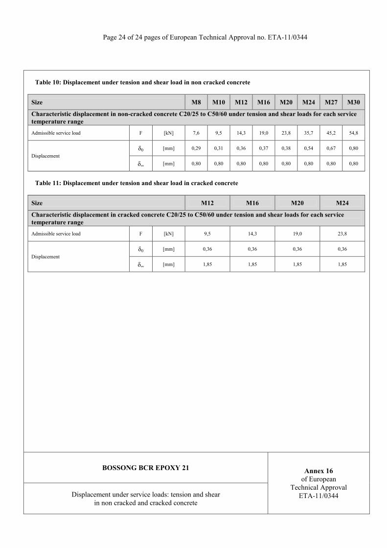
Table 10: Displacement under tension and shear load in non cracked concrete
Size M8 M10 M12 M16 M20 M24 M27 M30
Characteristic displacement in non-cracked concrete C20/25 to C50/60 under tension and shear loads for each service temperature range
Admissible service load F [kN] 7,6 9,5 14,3 19,0 23,8 35,7 45,2 54,8
Displacementδ0 [mm] 0,29 0,31 0,36 0,37 0,38 0,54 0,67 0,80
δ∞ [mm] 0,80 0,80 0,80 0,80 0,80 0,80 0,80 0,80
Table 11: Displacement under tension and shear load in cracked concrete
Size M12 M16 M20 M24
Characteristic displacement in cracked concrete C20/25 to C50/60 under tension and shear loads for each service temperature range
Admissible service load F [kN] 9,5 14,3 19,0 23,8
Displacementδ0 [mm] 0,36 0,36 0,36 0,36
δ∞ [mm] 1,85 1,85 1,85 1,85
BOSSONG BCR EPOXY 21 Annex 16of European
Technical Approval ETA-11/0344 Displacement under service loads: tension and shear
in non cracked and cracked concrete


