44
CAT.ES30-7 C Membrane Air Dryer Series IDG Macromolecular membrane dryers that act like filters New 10, 600, 750 & 1000l/min (ANR) models added to IDG Series!

CAT.ES30-7 C
Membrane Air Dryer
Series IDGMacromolecular membranedryers that act like filters
New 10, 600, 750 & 1000l/min (ANR) models added to IDG Series!
• Compact• Lightweight
• Space saving
Environmentallyfriendly (non-freon)
Integratedpre-filter
Compatible with outlet airatmospheric pressure dew points
as low as – 40˚C.IDG30L, IDG50L, IDG60L
IDG75L, IDG100L
Dew point indicatorconfirms air drying at a glance(except IDG1)(optional on IDG5, IDG5H)
Applications Dehumidification principle
Orifice
Hollow fibers
Humid compressed air
Dry air
Air(oxygen, nitrogen, etc.)
Moisture
Purgeair
Series IDG Membrane Air Dryer
IDG30MIDG10V IDG60M
Also available as a unit in which pre-filters (AFM, AFD, AMH) are combined with the membrane air dryer.
Compatible withlow dew points
Except IDG1, IDG5, IDG5H, IDG30,IDG30H, IDG30L, IDG50,
IDG50H, IDG50L
Discharged airnoise reduced
with built-in silencer
• Precision machines (air bearings, lasers, etc.)
• Precision measuring equipment (3-D measuring machines)
• Semiconductor manufacturing equipment
• Semiconductor inspection equipment• Chemical analysis equipment• Ozonizers• Packaging machines• Paper making machines• Fine particle transfer equipment• Electrostatic and high grade coating• Drying and cleaning of precision parts• Condensation prevention in control panels
• General pneumatic equipment and pneumatic tools
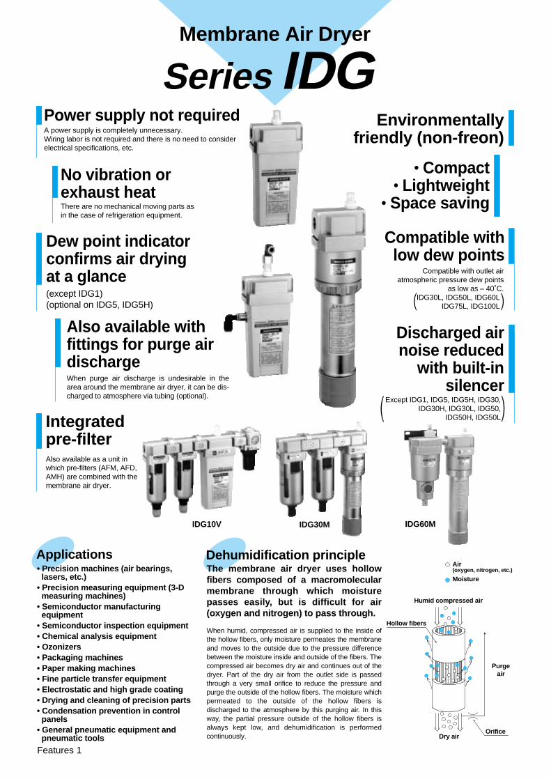
The membrane air dryer uses hollow fibers composed of a macromolecular membrane through which moisture passes easily, but is difficult for air (oxygen and nitrogen) to pass through.
When humid, compressed air is supplied to the inside of the hollow fibers, only moisture permeates the membrane and moves to the outside due to the pressure difference between the moisture inside and outside of the fibers. The compressed air becomes dry air and continues out of the dryer. Part of the dry air from the outlet side is passed through a very small orifice to reduce the pressure and purge the outside of the hollow fibers. The moisture which permeated to the outside of the hollow fibers is discharged to the atmosphere by this purging air. In this way, the partial pressure outside of the hollow fibers is always kept low, and dehumidification is performed continuously.
Also available with fittings for purge air dischargeWhen purge air discharge is undesirable in the area around the membrane air dryer, it can be dis-charged to atmosphere via tubing (optional).
No vibration or exhaust heatThere are no mechanical moving parts asin the case of refrigeration equipment.
Power supply not requiredA power supply is completely unnecessary.Wiring labor is not required and there is no need to consider electrical specifications, etc.
Features 1

Series Variations
Table of Contents
Standard Purging Low Purging Low Dew Point
Series Series SeriesOutlet air flow rate
l/min (ANR)
IDG1
IDG5
IDG10
IDG20
IDG30
IDG50
IDG60
IDG75
IDG100
10
50
100
200
300
500
600
750
1000
IDG5H
IDG10H
IDG20H
IDG30H
IDG50H
IDG60H
IDG75H
IDG100H
50
100
200
300
500
600
750
1000
Standard dew point: – 20°C Note)
Standard purging rate: 20%
Series IDG
MistSeparator
MicroMist Separator
MembraneAir Dryer
Standard dew point: –15°C Note)
Standard purging rate: 10% Standard dew point: – 40°C Note)
Standatd purging rate: 25%
IDG30L
IDG50L
IDG60L
IDG75L
IDG100L
75
110
170
240
300
IDG5M
IDG10M
IDG20M
IDG30M
IDG50M
IDG60M
IDG75M
IDG100M
50
100
200
300
500
600
750
1000
IDG5HM
IDG10HM
IDG20HM
IDG30HM
IDG50HM
IDG60HM
IDG75HM
IDG100HM
50
100
200
300
500
600
750
1000
IDG30LM
IDG50LM
IDG60LM
IDG75LM
IDG100LM
75
110
170
240
300
IDG5V
IDG10V
IDG20V
IDG30V
IDG50V
IDG60V
IDG75V
IDG100V
50
100
200
300
500
600
750
1000
IDG5HV
IDG10HV
IDG20HV
IDG30HV
IDG50HV
IDG60HV
IDG75HV
IDG100HV
50
100
200
300
500
600
750
1000
IDG30LV
IDG50LV
IDG60LV
IDG75LV
IDG100LV
75
110
170
240
300
Un
it S
tyle
Sin
gle
Sty
le
MistSeparator
MicroMist Separator
MembraneAir Dryer Regulator
Unit Style
How to Order P.12Standard Specifications (Standard Dew Point – 20°C) P.13Replacement Part Nos. P.13Standard Specifications (Standard Dew Point – 15°C) P.14Replacement Part Nos. P.14Standard Specifications (Standard Dew Point – 40°C) P.15Replacement Part Nos. P.15Flow Rate Characteristics P.16Dimensions (M Type) P.18Dimensions (V Type) P.23
Single StyleStandard Dew Point – 20°C SpecificationsHow to Order, Accessory Part Nos. P. 1Standard Specifications P. 1Performance Charts P. 2Standard Dew Point –15°C SpecificationsHow to Order, Accessory Part Nos. P. 4Standard Specifications P. 4Performance Charts P. 5Standard Dew Point – 40°C SpecificationsHow to Order, Accessory Part Nos. P. 6Standard Specifications P. 6Performance Charts P. 7Construction P. 8Dimensions P.10
IDG/M TypeA mist separator and micro mist separator, or micro mist separator with pre-filter are combined with the single styles
IDG/V TypeA regulator is combined with the M type
Note) Standard dew point: Outlet air atmospheric pressure dew point under standard performance conditionsStandard purging rate: Ratio of purge air flow rate to inlet air flow rate under standard performance conditionsOutlet air flow rate: Value under standard performance conditions
Note)Outlet air flow rate
l/min (ANR)
Note)Outlet air flow rate
l/min (ANR)
Note)
Model Selection MethodModel Selection P.28Flow Rate Characteristics P.30Purge Air Flow Rate Charts P.32
Precautions
Safety Instructions P.34Cleaning Equipment Precautions P.35Specific Product Precautions P.37
Features 2


15
Size
102030506075
100
How to Order
Flow rate by size
Thread typeRc
NPTG
Optional specifications
Port size
AccessoriesNone (standard)With bracket (except IDG1)
IDG 10 — 03 —
Single Style/Standard Dew Point – 20°C Specifications
01 1/802 1/403 3/8
Symbol BoreSizes
1 5 10 20 30— � — — —� � � � �
— — � � �
04 1/2 — — — — —
50—�
�
—
60——�
�
75———�
100———�
Nil StandardWith fitting for purge air dischargeFlow direction (right→left)With dew point indicator
PR
Symbol ContentsSizes
1 5 10 20 30� � � � �
� � � � �
— � � � �
S — �
50�
�
�
Standard equipment
60�
�
�
75�
�
�
100�
�
�
Note ) In case of two or more options, indicate in alphabetical order.
Bracket assembly (accessory) part nos.Part No. Applicable models
BM59
BM61
BM63
BM64
IDG5, IDG5H
IDG10, IDG10H
IDG20, IDG20H
IDG30, IDG30H, IDG30LIDG50, IDG50H, IDG50L
BM65IDG60, IDG60H, IDG60LIDG75, IDG75H, IDG75LIDG100, IDG100H, IDG100L
Standard Specifications/Single Style (Standard Dew Point – 20°C)
ModelStandard Dew Point – 20°C
Fluid Compressed air
Inlet air temperature Note 1) – 5 to 55°CAmbient temperature
Inlet air temperatureInlet air saturation temperature Ambient temperature
Outlet air atmosphericpressure dew point
Inlet air flow ratel/min (ANR) Note 2)
Outlet air flow ratel/min (ANR)
Purge air flow ratel/min (ANR) Note 3)
Inlet air pressureMPa
Dew point indicator purge air flow ratePort size (nominal size B)Weight kg(with bracket)
Inlet air pressure MPa 0.3 to 0.85 0.3 to 1.0
Rang
e of o
pera
ting
cond
ition
sS
tan
dar
d p
erfo
rman
ceco
nd
itio
ns
Sta
ndard
perfo
rman
ce
– 5 to 50°C– 5 to 55°C
– 20°C
– 5 to 50°C
IDG1 IDG5 IDG10 IDG20 IDG30 IDG50 IDG60 IDG75 IDG100
12.5 62562 125 250 375
0.7
25°C25°C25°C
1l /min (ANR) {inlet air pressure at 0.7MPa}—
725 900 1190
10 50 100 200 300 500 600 750 1000
2.5 12 25 50 75 125 125 150 190
0.11 0.25(0.31)
0.43(0.51)
0.66(0.76)
0.74(0.87)
0.77(0.90)
1.50(1.65)
1.50(1.65)
1.55(1.70)
1/4 1/4, 3/81/8, 1/4 1/23/8, 1/2
Note 1) With no freezing.Note 2) ANR indicates the flow rate converted to the value for 20°C at atmospheric pressure.Note 3) Includes dew point indicator purge air flow rate of 1 l/min (ANR) (inlet air pressure at 0.7MPa) (except IDG1, IDG5 ).∗ With cap bolts and spring washers
IDG1
IDG10
IDG30JIS symbol
Outlet air flow rate––––––––––––––––––
Purge air flow rate l/min (ANR)
10/2.550/12100/25200/50300/75500/125600/125750/1501000/190
NilNF
NilB
Note) When symbol B is indicated, a bracket assembly with a part number shown in the table below is included as an accessory.
Air Dryer
1
Membrane Air Dryer
Series IDG

Performance Charts
IDG1
Outlet air flow rate l /min (ANR)Out
let a
ir at
mos
pher
ic p
ress
ure
dew
poi
nt °
C
– 40
– 30
– 20
– 10
0
4 8 12 160
IDG10
IDG5
Outlet air flow rate l /min (ANR)Out
let a
ir at
mos
pher
ic p
ress
ure
dew
poi
nt °
C
– 40
– 30
– 20
– 10
0
20 40 60 800
P1= 0.3MPa
P1= 0.5MPa
P1= 0.7MPa
Outlet air flow rate l /min (ANR)Out
let a
ir at
mos
pher
ic p
ress
ure
dew
poi
nt °
C
– 40
– 30
– 20
– 10
0
0 40 80 120 160
P1= 0.3MPa
P1= 0.5MPa
P1= 0.7MPa
IDG60
IDG20
Outlet air flow rate l /min (ANR)Out
let a
ir at
mos
pher
ic p
ress
ure
dew
poi
nt °
C
0– 40
– 30
– 20
– 10
0
100 200 300
P1= 0.3MPa
P1= 0.5MPa
P1= 0.7MPa
Outlet air flow rate l /min (ANR)
Out
let a
ir at
mos
pher
ic p
ress
ure
dew
poi
nt °
C
– 50
– 40
– 30
– 20
– 10
0
0 200 400 600 800
IDG75
Outlet air flow rate l /min (ANR)Out
let a
ir at
mos
pher
ic p
ress
ure
dew
poi
nt °
C
– 50
– 40
– 30
– 20
– 10
0
0 200 400 600 800 1000
IDG30
Outlet air flow rate l /min (ANR)Out
let a
ir at
mos
pher
ic p
ress
ure
dew
poi
nt °
C
– 50
– 40
– 30
– 20
– 10
0
0 100 200 300 400 500
P1= 0.3MPa
P1= 0.5MPa
P1= 0.7MPa
IDG50
Outlet air flow rate l /min (ANR)Out
let a
ir at
mos
pher
ic p
ress
ure
dew
poi
nt °
C
– 500 200 400 600 800
– 10
– 40
– 30
– 20
0 P1= 0.3MPa
P1= 0.5MPa
P1= 0.7MPa
P1= 0.3MPa
P1= 0.5MPa
P1= 0.7MPa
P1= 0.3MPa
P1= 0.5MPa
P1= 0.7MPa
P1= 0.3MPa
P1= 0.5MPa
P1= 0.7MPa
Series IDG
2
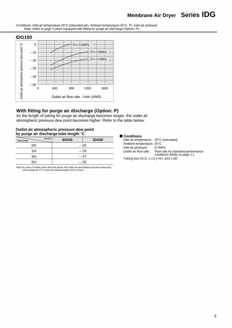
IDG100
Outlet air flow rate l /min (ANR)Out
let a
ir at
mos
pher
ic p
ress
ure
dew
poi
nt °C
0 400 800 1200 1600– 50
– 40
– 30
– 20
– 10
0
Outlet air atmospheric pressure dew pointby purge air discharge tube length °CTube length
Model� Conditions
IDG30 IDG50
– 20
– 19
– 17
– 16
0m
1m
3m
5m
P1= 0.3MPa
P1= 0.5MPa
P1= 0.7MPa
Conditions: Inlet air temperature 25°C (saturated air), Ambient temperature 25°C, P1: Inlet air pressure Note: Refer to page 3 when equipped with fitting for purge air discharge (Option: P).
With fitting for purge air discharge (Option: P)As the length of tubing for purge air discharge becomes longer, the outlet air atmospheric pressure dew point becomes higher. Refer to the table below.
Inlet air temperature: 25°C (saturated)Ambient temperature: 25°CInlet air pressure: 0.7MPa Outlet air flow rate: Flow rate for standard performance
conditions (Refer to page 1.)Tubing size (O.D. x I.D.) mm: ø12 x ø9
Note) In case of models other than the above, the outlet air atmospheric pressure dew point will increase by 1°C or less for tubing lengths of 5m or less.
3
Membrane Air Dryer Series IDG
How to Order
Single Style/Standard Dew Point –15°C Specifications
Bracket assembly (accessory) part nos.Part No. Applicable models
BM59
BM61
BM63
BM64
IDG5, IDG5H
IDG10, IDG10H
IDG20, IDG20H
IDG30, IDG30H, IDG30LIDG50, IDG50H, IDG50L
BM65IDG60, IDG60H, IDG60LIDG75, IDG75H, IDG75LIDG100, IDG100H, IDG100L
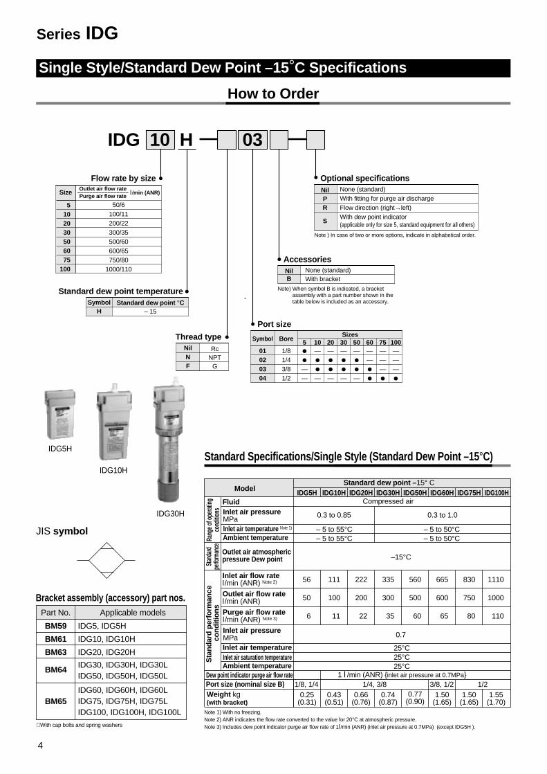
Standard Specifications/Single Style (Standard Dew Point –15°C)
ModelStandard dew point –15° C
Fluid Compressed air
Inlet air temperature Note 1) – 5 to 55°CAmbient temperature
Inlet air temperatureInlet air saturation temperature Ambient temperature
Outlet air atmosphericpressure Dew point
Inlet air flow ratel/min (ANR) Note 2)
Outlet air flow ratel/min (ANR)
Purge air flow ratel/min (ANR) Note 3)
Inlet air pressureMPa
Dew point indicator purge air flow ratePort size (nominal size B)Weight kg(with bracket)
Inlet air pressure MPa 0.3 to 0.85 0.3 to 1.0
Rang
e of o
pera
ting
cond
itions
Sta
nd
ard
per
form
ance
co
nd
itio
ns
Stand
ardpe
rform
ance
– 5 to 50°C– 5 to 55°C
–15°C
– 5 to 50°C
IDG5H IDG10H IDG20H IDG30H IDG50H IDG60H IDG75H IDG100H
56 665111 222 335 560
0.7
25°C25°C25°C
1 l /min (ANR) {inlet air pressure at 0.7MPa}
830 1110
50 100 200 300 500 600 750 1000
6 11 22 35 60 65 80 110
0.25(0.31)
0.43(0.51)
0.66(0.76)
0.74(0.87)
0.77(0.90)
1.50(1.65)
1.50(1.65)
1.55(1.70)
1/4, 3/81/8, 1/4 1/23/8, 1/2
Note 1) With no freezing.Note 2) ANR indicates the flow rate converted to the value for 20°C at atmospheric pressure.Note 3) Includes dew point indicator purge air flow rate of 1l/min (ANR) (inlet air pressure at 0.7MPa) (except IDG5H ).∗ With cap bolts and spring washers
IDG5H
IDG10H
IDG30H
JIS symbol
Thread typeRc
NPTG
Optional specifications
Port size
Standard dew point temperatureStandard dew point °C
– 15Symbol
H
AccessoriesNilB
IDG 10 H — 03 —
01 1/802 1/403 3/8
Symbol BoreSizes
5 10 20 30� — — —� � � �
— � � �
04 1/2 — — — —
50—�
�
—
60——�
�
75———�
100———�
Note ) In case of two or more options, indicate in alphabetical order.
5
Size
102030506075
100
Flow rate by sizeOutlet air flow rate
–––––––––––––––––Purge air flow rate
l/min (ANR)
50/6100/11200/22300/35500/60600/65750/80
1000/110
NilPR
S
None (standard)With fitting for purge air dischargeFlow direction (right→left)With dew point indicator(applicable only for size 5, standard equipment for all others)
None (standard)With bracket
Note) When symbol B is indicated, a bracket assembly with a part number shown in the table below is included as an accessory.
NilNF
Series IDG
4

Performance Charts
IDG5H
IDG20H
ID10H
IDG75H
IDG30H
Outlet air flow rate l/min (ANR)Out
let a
ir at
mos
pher
ic p
ress
ure
dew
poi
nt °
C
– 50
– 40
– 30
– 20
– 10
0
0 200 400 600 1000800
IDG100H
Outlet air flow rate l /min (ANR)Out
let a
ir at
mos
pher
ic p
ress
ure
dew
poi
nt °
C
– 50
– 40
– 30
– 20
– 10
0
0 400 800 1200 1600
IDG50H IDG60H
Outlet air flow rate l /min (ANR)Out
let a
ir at
mos
pher
ic p
ress
ure
dew
poi
nt °
C
– 500 200 400 600 800
– 10
– 40
– 30
– 20
0 P1= 0.3MPa
P1= 0.5MPa
P1= 0.7MPa
P1= 0.3MPa
P1= 0.5MPa
P1= 0.7MPa
P1= 0.3MPa
P1= 0.5MPa
P1= 0.7MPa
Outlet air flow rate l /min (ANR)Out
let a
ir at
mos
pher
ic p
ress
ure
dew
poi
nt °
C
– 40
– 30
– 20
– 10
0
0 40 80 120 160
P1= 0.3MPa
P1= 0.5MPa
P1= 0.7MPa
Outlet air flow rate l /min (ANR)
Out
let a
ir at
mos
pher
ic p
ress
ure
dew
poi
nt °
C
1000 200 300
– 20
– 10
0
– 30
P1= 0.3MPa
P1= 0.5MPa
P1= 0.7MPa
Outlet air flow rate l /min (ANR)Out
let a
ir at
mos
pher
ic p
ress
ure
dew
poi
nt °
C
– 50
– 40
– 30
– 20
– 10
0
0 100 200 300 400 500
P1= 0.3MPa
P1= 0.5MPa
P1= 0.7MPa
Outlet air flow rate l /min (ANR)Out
let a
ir at
mos
pher
ic p
ress
ure
dew
poi
nt °
C
– 506000 200 400 800
– 10
– 40
– 30
– 20
0 P1= 0.3MPa
P1= 0.5MPa
P1= 0.7MPa
Outlet air flow rate l /min (ANR)Out
let a
ir at
mos
pher
ic p
ress
ure
dew
poi
nt °
C
– 40
– 30
– 20
– 10
0
20 40 60 800
P1= 0.3MPa
P1= 0.5MPa
P1= 0.7MPa
Conditions: Inlet air temperature 25°C (saturated air), Ambient temperature 25°C, P1: Inlet air pressure, Purge air discharge tube (Option: P): None
Note: When equipped with fitting for purge air discharge (Option: P), the outlet air atmospheric pressure dew point will rise by 1°C or less for tubing lengths of 5m or less.
5
Membrane Air Dryer Series IDG

How to Order
Single Style/Standard Dew Point –40°C Specifications
Bracket assembly (accessory) part nos.Part No. Applicable models
BM64 IDG30, IDG30H, IDG30LIDG50, IDG50H, IDG50L
BM65IDG60, IDG60H, IDG60LIDG75, IDG75H, IDG75LIDG100, IDG100H, IDG100L
Standard Specifications/Single Style (Standard dew point – 40°C)
ModelStandard dew point – 40°C
Fluid Compressed air
Inlet air temperature Note1) – 5 to 50°CAmbient temperature
Inlet air temperature Inlet air saturation temperatureAmbient temperature
Outlet air atmospheric pressure dew point
Inlet air flow ratel/min (ANR) Note 2)
Outlet air flow ratel/min (ANR)
Purge air flow ratel/min (ANR) Note 3)
Inlet air pressureMPa
Dew point indicator purge air flow ratePort size (nominal size B)Weight kg(with bracket)
Inlet air pressureMPa 0.3 to 1.0
Rang
e of o
pera
ting
cond
itions
Co
nd
itio
ns
for
stan
dar
dp
erfo
rman
ceSta
ndard
perfo
rman
ce
– 5 to 50°C
– 40 (– 50)°C Note 4)
IDG30L IDG50L IDG60L IDG75L IDG100L
100 150 227 320 400
0.7
25°C25°C25°C
1 l/min (ANR) {inlet air pressure at 0.7MPa}
75 110 170 240 300
25 40 57 80 100
0.74(0.87)
0.77(0.90)
1.50(1.65)
1.65(1.80)
1.80(1.95)
3/8, 1/21/4, 3/8
Note 1) With no freezing.Note 2) ANR indicates the flow rate converted to the value for 20°C at atmospheric pressure.Note 3) Includes dew point indicator purge air flow rate of 1l/min (ANR) (inlet air pressure at 0.7MPa). Note 4) Values inside ( ) are applicable with a refrigeration type air dryer installed on the upstream side.∗ With cap bolts and spring washers
IDG30L
JIS symbol
Thread type
Optional specifications
Port size
Standard dew point temperatureStandard dew point °C
– 40
AccessoriesNone (standard)With bracket
IDG 50 L — 03 —
02 1/403 3/8
Symbol BoreSizes
30�
�
04 1/2 —
50�
�
—
60—�
�
75—�
�
100—�
�
None (standard)With purge air discharge fittingFlow direction (right→left)
Size
30506075
100
Flow rate by sizeOutlet air flow rate––––––––––––––––Purge air flow rate l/min (ANR)
75/25110/40170/57240/80
300/100
SymbolL
RcNPT
G
NilNF
Note) When symbol B is indicated, a bracket assembly with a part number shown in the table below is included as an accessory.
NilB
NilPR
Note ) In case of two or more options, indicate in alphabetical order.
Series IDG
6

IDG30L
Outlet air flow rate l/min (ANR)Out
let a
ir at
mos
pher
ic pr
essu
re d
ew p
oint
°C
0 20 40 60 80 100
– 60
– 50
– 40
– 30
– 20
– 10
0
– 70
P1= 0.3MPa
P1= 0.5MPa
P1= 0.7MPa
IDG50L
Outlet air flow rate l/min (ANR)Out
let a
ir at
mos
pher
ic pr
essu
re d
ew p
oint
°C
– 700
– 60
– 50
– 40
– 30
– 20
– 10
0
16040 80 120
P1= 0.3MPa
P1= 0.5MPa
P1= 0.7MPa
IDG60L
Outlet air flow rate l/min (ANR)Out
let a
ir at
mos
pher
ic pr
essu
re d
ew p
oint
°C
0 40 80 120 160 200
– 60
– 50
– 40
– 30
– 20
–10
0
– 70
IDG75L
Outlet air flow rate l/min (ANR)Out
let a
ir at
mos
pher
ic pr
essu
re d
ew p
oint
°C
– 700
– 60
– 50
– 40
– 30
– 20
– 10
0
100 200 300
IDG100L
Outlet air flow rate l/min (ANR)Out
let a
ir at
mos
pher
ic pr
essu
re d
ew p
oint
°C
0 100 200 300 400
– 60
– 50
– 40
– 30
– 20
– 10
0
– 70
Performance Charts
P1= 0.3MPa
P1= 0.5MPa
P1= 0.7MPa
P1= 0.3MPa
P1= 0.5MPa
P1= 0.7MPa
P1= 0.3MPa
P1= 0.5MPa
P1= 0.7MPa
Outlet air atmospheric pressure dew point °C by purge air discharge tube length
Tube length Model � ConditionsIDG30L IDG50L
– 40
– 39
– 38
0m
1m
3m
5m
Conditions: Inlet air temperature 25°C (saturated air), Ambient temperature 25°C P1: Inlet air pressure, Tube for purge air discharge (Option: P): None
Note) In case of models other than the above, the outlet air atmospheric pressure dew point will increase by 1°C or less for tubing lengths of 5m or less.
Inlet air temperature: 25°C (saturated)Ambient temperature: 25°CInlet air pressure: 0.7MPa Outlet air flow rate: Flow rate for standard performance conditions
(refer to page 6)Tubing size (O.D. x I.D.) mm: ø12 x ø9
Fitting for purge air discharge (Option: P)As the length of tubing for purge air discharge becomes longer, the outlet air atmospheric pressure dew point becomes higher.Refer to the table below.
7
Membrane Air Dryer Series IDG

IDG1
Optional specificationsWith fitting for purge air discharge (Option: P)
Purge
Optional specifications
With fitting for purge airdischarge (Option: P)
Optional specifications
With fitting for purge airdischarge (Option: P)
IDG5, IDG5H IDG10, IDG10HIDG20, IDG20H
Construction
Parts list
No.
123456
Description
Body
Female connector
Strainer
Case
Orifice
Silencer
Copper alloy
Copper alloy
Copper alloy
—
Resin
—
Aluminum alloy
—
—
Stainless
IDG1 IDG5, 5H IDG10, 10H IDG20, 20H
IDG1 IDG5, 5H IDG10, 10H IDG20, 20H
Resin
Material
Platinum silver coating (IDG1 is electroless nickel plated)
Electroless nickel plated
Replacement parts
No.
7
89
Description Note
Note
IDG-DP01-X001
IDG-EL10 IDG-EL10H
IDG-EL20 IDG-EL20H
Dew point indicator set
Membrane module set
—
—
—
— Copper alloy
IDG-EL5 IDG-EL5H
IDG-DP01
—
—
—
Part Nos.
With option: P
Purge
Purge
Purge
Purge
IN
Purge
OUT
OUTIN
IN
IN OUT
Series IDG
8

IDG30, IDG30H, IDG30LIDG50, IDG50H, IDG50L
IDG60, IDG60H, IDG60LIDG75, IDG75H, IDG75LIDG100, IDG100H, IDG100L
Parts list
No.
12345
Description
Body
Case
Orifice
Holder
SilencerAluminum alloy
—
Aluminum
Resin + Copper alloy
Aluminum alloy
Stainless steel
Stainless steel
IDG30, 30H, 30L IDG50, 50H, 50L IDG60, 60H, 60L IDG75, 75H, 75L IDG100, 100H, 100L
IDG30, 30H, 30L IDG50, 50H, 50L IDG60, 60H, 60L IDG75, 75H, 75L IDG100, 100H, 100L
Material
Platinum silver coating
Replacement parts
No.
6
78
Description Note
Note
IDG-EL60 IDG-EL60L
IDG-EL75 IDG-EL75L
IDG-EL100IDG-EL100LMembrane module set
Dew point indicator setIDG-DP01
IDG-DP01-X001
IDG-EL30 IDG-EL50
Part Nos.
With option: P
Optional specifications
With fitting for purgeair discharge (Option: P)
Optional specifications
With fitting for purgeair discharge (Option: P)
Purge
IN OUT
Purge Purge
IN
Purge
OUT
9
Membrane Air Dryer Series IDG

Dimensions
IDG1
IDG5, IDG5H
IDG10, IDG10HIDG20, IDG20H
Purge air fordehumidification
Port size: 1/8, 1/4
Bracket(Accessory: B)
(86)
(67)
(67)
(46) (26)
ø8
(34)
(25)
(293)
30
40
22
2.3
Port size L
Dew point indicator(Option: S)
Purge air outlet for dehumidification
Width across flats 19
INPort size: 1/4
OUTPort size: 1/4
With fitting for purge air discharge (Option: P)
With fittings for purge air discharge (Option: P)
2.3 Purge air discharge tubingport for dew point indicatorApplicable tube O.D.:ø8ø5/16 inch
Purge air fordehumidification
Bracket(Accessory: B)
23
Purge air discharge tubingport for dehumidificationApplicable tube O.D.:ø8ø5/16 inch
Purge air discharge tubingport for dehumidificationApplicable tube O.D.: øJ(NPT thread: øK inch)
C41
(H)
(98)
(G)
(F)
(64)
IDG10, IDG10HIDG20, IDG20H Values inside [ ] are for NPT threads
Models
1/4, 3/8
Option: PPort sizeL A B C D E
83 187 53 165 62113 212 54 190 82
F G JH K 97 224 8119 [126] 5/16114 249 10147 [154] 3/8
With fitting for purge air discharge (Option: P)
Purge air outlet for dehumidification
Width across flats 14
Width across flats 17
Purge air discharge tubing portfor dehumidificationApplicable tube O.D.: ø6(with NPT thread: ø1/4 inch)
Width across flats 14Width across flats 14
Width across flats 17
(Maintenance space 100mm or more)
Purge air
11
Purge air fordehumidification
73
17
IN
38
118 14
0
6
12
OUT
(Maintenance space 100mm or more)
IN
1416
D
B
OUT
7
Purge airEA
14
Series IDG
10
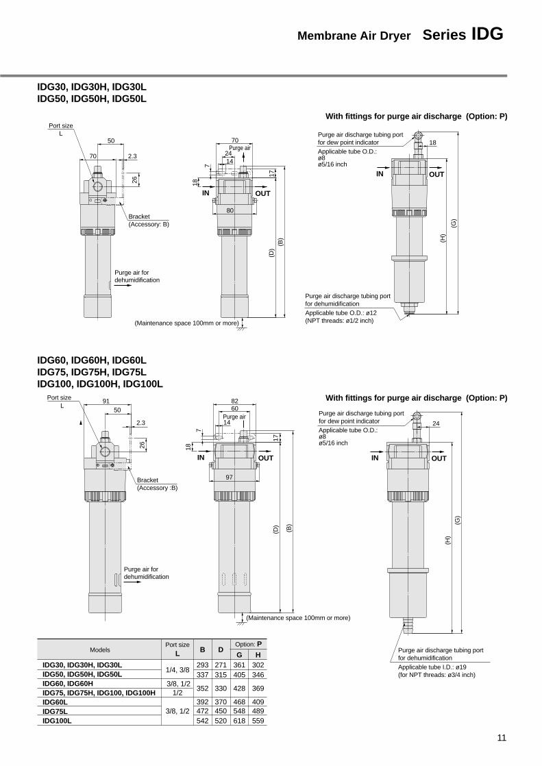
IDG30, IDG30H, IDG30LIDG50, IDG50H, IDG50L
IDG60, IDG60H, IDG60LIDG75, IDG75H, IDG75LIDG100, IDG100H, IDG100L
3/8, 1/21/2
3/8, 1/2
IDG60, IDG60H330352 369428
IDG75, IDG75H, IDG100, IDG100HIDG60L 370392 409468IDG75L 450472 489548IDG100L 520542 559618
IN OUT
IN OUT
With fittings for purge air discharge (Option: P)
Purge air
Purge air discharge tubing portfor dehumidificationApplicable tube O.D.: ø12(NPT threads: ø1/2 inch)
7
17
(G
)
(H
)
(D
) (B
)
18
24
70 18
80
14
Purge air discharge tubing portfor dew point indicatorApplicable tube O.D.:ø8ø5/16 inch
(Maintenance space 100mm or more)
Bracket(Accessory: B)
Port sizeL
Purge air fordehumidification
26
70 2.3
50
IDG30, IDG30H, IDG30LIDG50, IDG50H, IDG50L
Models
1/4, 3/8
Option: PPort sizeL D
271315
B
293337
H302346
G361405
Purge air
IN OUT IN OUT
With fittings for purge air discharge (Option: P)
24
82
97
7
17
(B
)
(D
) (G
)
(H
)
18
60
14Purge air discharge tubing portfor dew point indicatorApplicable tube O.D.:ø8ø5/16 inch
(Maintenance space 100mm or more)
Purge air discharge tubing portfor dehumidificationApplicable tube I.D.: ø19(for NPT threads: ø3/4 inch)
Port size
OUT
50
2.3
91L
26
Bracket(Accessory :B)
Purge air fordehumidification
11
Membrane Air Dryer Series IDG

Component equipment
Thread typeNilNF
Optional specifications
Drain discharge method(Mist separator, Micro mist separator, Micro mist separator with pre-filter )
IDG 30 M— 03 —
Nil Manual valveN.C. auto drainN.O. auto drain
CD
Symbol Drain dischargemethod
Sizes
JDrain guide
bore 1/4without valvemechanism
Note) Note)
IDG5 to IDG50
M
IDG5H to IDG50H
V
IDG30L, IDG50L
Sym
bo
l
Co
nte
nts
Models
Description
� � — � —� � — � —� � — � —
IDG60 to IDG100IDG60H to IDG100HIDG60L to IDG100L
— — � � —— — � � —� � — � —
IDG5 to IDG50IDG5H to IDG50HIDG30L, IDG50L
� � — � �
� � — � �
� � — � �
IDG60 to IDG100IDG60H to IDG100HIDG60L to IDG100L
— — � � �
— — � � �
� � — � �
Note) For standard dew point – 40°C (symbol L) only
Nil None (standard)
With fitting forpurge air discharge
Flow direction (right→left)With dew point indicator
RcP
R
Symbol ContentsSizes
5 10 20 30 50� � � � �
� � �� �
� � � � �S � Standard equipment
60�
�
�
75�
�
�
100�
�
�
Port size
01 1/802 1/403 3/8
Symbol BoreSizes
5 10 20 30 50� — — — —� � � � �
— � � � �
60——�
75——
�
100——
�04 1/2 — — — — — � � �
5102030506075
100
Size
Standard dew point temperature and air flow rate
5 10 20 30 50� � � � �
— � � � �
60�
�
75�
�
100�
— � � — — — — —
� — — � � � � �
�
With
sep
arat
orW
ith r
egul
ator
and
sepa
rato
r
Regu
lato
r
Mem
bra
ne
air
dry
er
Mic
ro m
ist
sepa
rato
rw
ith p
re-fi
lter
Mic
ro m
ist
sep
arat
or
Mis
t sep
arat
or
How to Order
Units (M Type, V Type)
550/1250/6—
10100/25100/11
—
20200/50200/22
—
30300/75300/3575/25
50500/125500/60110/40
60600/125600/65170/57
75750/150750/80240/80
100
1000/110300/100
Outlet air flow ratePurge air flow rate
( )
Symbol
NilHL
Standarddewpoint°C
– 20– 15– 40
Flow rate by size l/min (ANR)
Note) • A differential pressure type auto drain is used for body size 5.• When symbols C or D are specified, an auto drain with a part
number shown on page 13 is mounted.
Note)
1000/190
RcNPT
G
Note) • In case of two or more options, indicate them in an alphabetical order.
• Symbol P is for M type only.
Air Dryer
12
Membrane Air Dryer Unit

Part numbers/Auto drain, Case assembly, Pressure gauge
Float type auto drain
Differential pressure type auto drain
Pressure gauge (V type only)
AD62
— AD53
GC30-10
Case assembly (N.O.) AMH-CA350-D AMH-CA450-D
—
N.C.
N.O.
IDG5MIDG5V
IDG50MIDG50V
— —
— —
— — — — —
AD44
— — — — —
— — —
— — —
— —
IDG30MIDG30V
IDG20MIDG20V
IDG100MIDG100V
IDG75MIDG75V
IDG60MIDG60V
IDG10MIDG10V
Standard Specifications/Units (M Type, V Type) [Standard Dew Point – 20°C]
ModelsStandard dew point –20°C
Fluid
Micro mist separatorMist separator
Micro mist separator with pre-filter
Compressed air
Inlet air temperature –5 to 55°C Note1) 5 to 50°CAmbient temperature
Inlet air temperatureInlet air saturation temperatureAmbient temperature
Outlet air atmosphericpressure dew pointInlet air flow ratel/min (ANR) Note 2)
Outlet air flow ratel/min (ANR)
Purge air flow ratel/min (ANR) Note 3)
Inlet air pressureMPa
Dew point indicator purge air flow rate
Port size (nominal size B)
M type
V type
Weight kg(with auto drain)
Inlet air pressureMPa 0.3 to 0.85 0.3 to 1.0
Ran
ge
of
op
erat
ing
con
diti
on
s
Com
pone
nteq
uipm
ent
Sta
nd
ard
per
form
ance
con
diti
on
s
– 5 to 50°C–5 to 55°C
– 20°C
5 to 50°C– 5 to 50°C
IDG5M
AFM2000AFD2000
——
AFM3000AFD3000
AFM4000AFD4000
— AMH450AMH350Regulator (V type only) AR2001 AR2501 AR4001
IDG10M IDG20M IDG30M IDG50M IDG60M IDG75M IDG100MIDG5V IDG10V IDG20V IDG30V IDG50V IDG60V IDG75V IDG100V
62 125 250 375 625
0.7
25°C25°C25°C
1 l/min (ANR) {inlet air pressure at 0.7MPa}
0.01µm (95% filtered particle size)
900 1190725
50 100 200 300 500 600 750 1000
12 25 50 75 125 125 150 190
1.28(1.35)
1.67(1.76)
1.90(1.99)
3.34(3.45)
3.37(3.48)
3.74(3.84)
4.29(4.39)
4.34(4.44)
0.83(0.90)
1.21(1.30)
1.44(1.53)
2.23(2.33)
2.26(2.36)
2.55(2.65)
3.10(3.20)
3.15(3.25)
1/8, 1/4 1/4, 3/8 3/8, 1/2 1/2
IDG30V
JIS symbol(M type) IDG5M to 50M IDG5V to 50V
Micro mist separator filtration degree
Relief typeRegulator construction (V type only)Micro mist separator with pre-filter filtration degree
Replacement parts (Mist separator, Micro mist separator, Element for micro mist separator with pre-filter)
Element assembly
AFD4000
63094
AFM4000
630623
AMH450
AMH-EL450
AMH350
AMH-EL350
AFD3000
63093
AFM3000
630617
AFD2000
63092
AFM2000
630611Refer to pages 8 and 9 for membrane air dryer replacement parts.
Mistseparator
Micro mistseparator
Membraneair dryer
IDG60M to 100M
Micro mistseparator with
pre-filter
Membraneair dryer
Applicable models
Description
ModelDescription
(V type)
Mistseparator
Micro mistseparator
RegulatorMembraneair dryer
IDG60V to 100V
Micro mistseparator with
pre-filter
RegulatorMembraneair dryer
Standardperformance
Note 1) With no freezing.Note 2) ANR indicates the flow rate converted to the value for 20°C at atmospheric pressure.Note 3) Includes dew point indicator purge air flow rate 1 l/min (ANR) (inlet air pressure at 0.7MPa) (except IDG5M and IDG5V).Note 4) Refer to CAT.E510-A "Modular Type Regulator with Built-in Pressure Gauge" for regulator flow rate characteristics and pressure characteristics.
Note1)
13
Membrane Air Dryer Series IDG
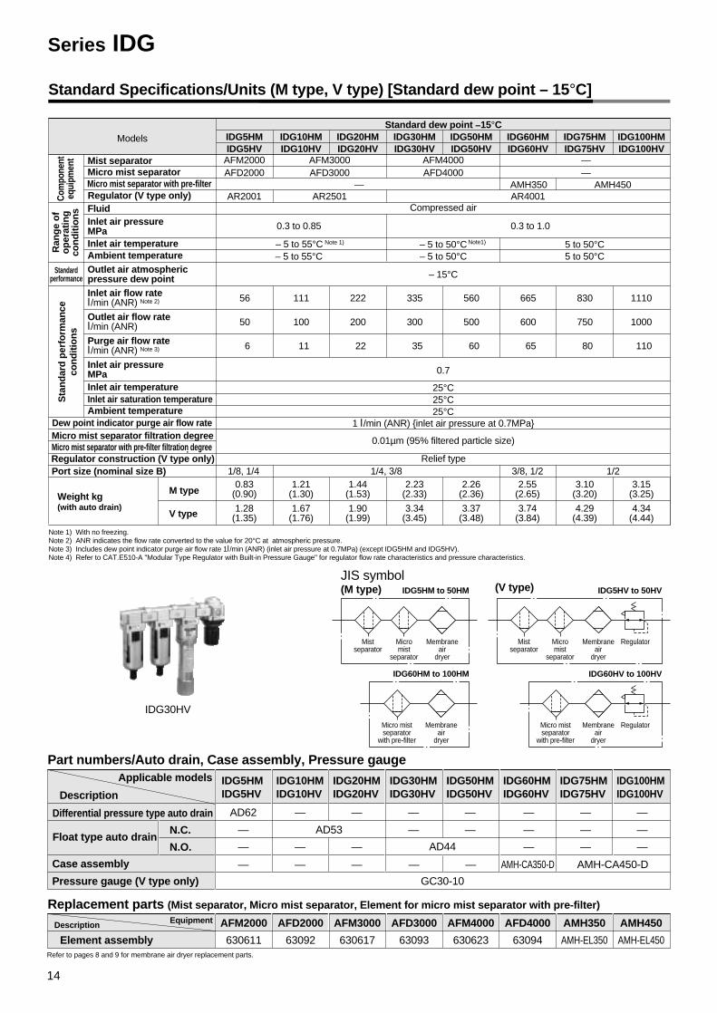
Standard Specifications/Units (M type, V type) [Standard dew point – 15°C]
ModelsStandard dew point –15°C
Fluid
Micro mist separatorMist separator
Micro mist separator with pre-filter
Compressed air
Inlet air temperature – 5 to 55°C Note 1) Note1) 5 to 50°CAmbient temperature
Inlet air temperatureInlet air saturation temperatureAmbient temperature
Outlet air atmosphericpressure dew point Inlet air flow ratel/min (ANR) Note 2)
Outlet air flow ratel/min (ANR) Purge air flow ratel/min (ANR) Note 3)
Inlet air pressureMPa
Dew point indicator purge air flow rate
Port size (nominal size B)
M type
V type
Weight kg(with auto drain)
Inlet air pressureMPa 0.3 to 0.85 0.3 to 1.0
Ran
ge
of
op
erat
ing
con
diti
on
s
Com
pone
nteq
uipm
ent
Sta
nd
ard
per
form
ance
con
diti
on
s
Standardperformance
– 5 to 50°C– 5 to 55°C
– 15°C
5 to 50°C– 5 to 50°C
IDG5HM
AFM2000AFD2000
——
AFM3000AFD3000
AFM4000AFD4000
— AMH450AMH350Regulator (V type only) AR2001 AR2501 AR4001
IDG10HM IDG20HM IDG30HM IDG50HM IDG60HM IDG75HM IDG100HMIDG5HV IDG10HV IDG20HV IDG30HV IDG50HV IDG60HV IDG75HV IDG100HV
56 111 222 335 560
0.7
25°C25°C25°C
1 l/min (ANR) {inlet air pressure at 0.7MPa}
0.01µm (95% filtered particle size)
830 1110665
50 100 200 300 500 600 750 1000
6 11 22 35 60 65 80 110
1.28(1.35)
1.67(1.76)
1.90(1.99)
3.34(3.45)
3.37(3.48)
3.74(3.84)
4.29(4.39)
4.34(4.44)
0.83(0.90)
1.21(1.30)
1.44(1.53)
2.23(2.33)
2.26(2.36)
2.55(2.65)
3.10(3.20)
3.15(3.25)
1/8, 1/4 1/4, 3/8 3/8, 1/2 1/2
Micro mist separator filtration degreeMicro mist separator with pre-filter filtration degree
Relief typeRegulator construction (V type only)
Part numbers/Auto drain, Case assembly, Pressure gauge
Replacement parts (Mist separator, Micro mist separator, Element for micro mist separator with pre-filter)
Refer to pages 8 and 9 for membrane air dryer replacement parts.
Float type auto drain
Differential pressure type auto drain
Pressure gauge (V type only)
AD62
— AD53
GC30-10
Case assembly AMH-CA350-D AMH-CA450-D
—
N.C.
N.O.
IDG5HMIDG5HV
IDG50HMIDG50HV
— —
— —
— — — — —
AD44
— — — — —
— — —
— — —
— —
IDG30HMIDG30HV
IDG20HMIDG20HV
IDG100HMIDG100HV
IDG75HMIDG75HV
IDG60HMIDG60HV
IDG10HMIDG10HV
Element assembly
AFD4000
63094
AFM4000
630623
AMH450
AMH-EL450
AMH350
AMH-EL350
AFD3000
63093
AFM3000
630617
AFD2000
63092
AFM2000
630611
Applicable models
Description
EquipmentDescription
IDG30HV
JIS symbol(M type) IDG5HM to 50HM IDG5HV to 50HV
IDG60HM to 100HM
(V type)
IDG60HV to 100HV
Mistseparator
Micromist
separator
Membraneair
dryer
Micro mistseparator
with pre-filter
Membraneair
dryer
Mistseparator
Micromist
separator
RegulatorMembraneair
dryer
Micro mistseparator
with pre-filter
RegulatorMembraneair
dryer
Note 1) With no freezing.Note 2) ANR indicates the flow rate converted to the value for 20°C at atmospheric pressure.Note 3) Includes dew point indicator purge air flow rate 1l/min (ANR) (inlet air pressure at 0.7MPa) (except IDG5HM and IDG5HV).Note 4) Refer to CAT.E510-A "Modular Type Regulator with Built-in Pressure Gauge" for regulator flow rate characteristics and pressure characteristics.
Series IDG
14

Standard Specifications/Units (M type, V type) [Standard Dew Point – 40°C]
Models
Standard dew point – 40°C
Fluid
Micro mist separatorMist separator
Regulator (V type only)Compressed air
Inlet air temperature Note 1)
Ambient temperature
Inlet air temperatureInlet air saturation temperatureAmbient temperature
Outlet air atmosphericpressure dew point Inlet air flow ratel/min (ANR) Note 2)
Outlet air flow ratel/min (ANR) Purge air flow ratel/min (ANR) Not 3)
Inlet air pressureMPa
Dew point indicator purge air flow rate
Port size (nominal size B)
M type
V type
Weight kg(with auto drain)
Inlet air pressureMPa 0.3 to 1.0
Ran
ge
of
op
erat
ing
con
diti
on
s
Componentequipment
Sta
nd
ard
per
form
ance
con
diti
on
s
Standardperformance
– 5 to 50°C
– 40 (– 50)°C
– 5 to 50°C
IDG30LM
AFM4000AFD4000AR4001
IDG50LM IDG60LM IDG75LM IDG100LMIDG30LV IDG50LV IDG60LV IDG75LV IDG100LV
100 150 227 320 400
0.7
25°C25°C25°C
1 l/min (ANR) {inlet air pressure at 0.7MPa}0.01µm (95% filtered particle size)
75 110 170 240 300
25 40 57 80 100
3.34(3.45)
3.37(3.48)
4.10(4.20)
4.25(4.35)
4.40(4.50)
2.23(2.33)
2.26(2.36)
2.99(3.09)
3.14(3.24)
3.29(3.39)
1/4, 3/8 3/8, 1/2Relief typeRegulator construction (V type only)
Note 4)
Micro mist separator filtration degree
IDG30LV
JIS symbol(M type)
Mistseparator
Micromist
separator
Membraneair
dryer
(V type)
Mistseparator
Micromist
separator
RegulatorMembraneair
dryer
Part numbers/Auto drain, Pressure gauge
Float type auto drain (N.O.)
GC30-10Pressure gauge
IDG30LMIDG30LV
IDG100LMIDG100LV
AD44
IDG75LMIDG75LV
IDG60LMIDG60LV
IDG50LMIDG50LV
Replacement parts (Mist separator, Micro mist separator element)
Element assembly
AFD4000
63094
AFM4000
630623Refer to pages 8 and 9 for membrane air dryer replacement parts.
Applicable models
Description
EquipmentDescription
Note 1) With no freezing.Note 2) ANR indicates the flow rate converted to the value for 20°C at atmospheric pressure.Note 3) Includes dew point indicator purge air flow rate 1l/min (ANR) (inlet air pressure at 0.7MPa).Note 4) Values inside ( ) are applicable when a refrigeration type air dryer is installed on the upstream side.Note 5) Refer to CAT.E510-A "Modular Type Regulator with Built-in Pressure Gauge" for regulator flow rate characteristics and pressure characteristics.
15
Membrane Air Dryer Series IDG

IDG5M, IDG5HMIDG5V, IDG5HV
IDG10M, IDG10HMIDG10V, IDG10HV
IDG20M, IDG20HMIDG20V, IDG20HV
Flow Rate Characteristics
IDG30M, IDG30HM, IDG30LMIDG30V, IDG30HV, IDG30LV
IDG50M, IDG50HM, IDG50LMIDG50V, IDG50HV, IDG50LV
Inlet air flow rate l /min (ANR)
Pre
ssur
e dr
op M
Pa
0
0.02
0.04
0.06
0.08
0.10
0.12
Element saturated state (AFM, AFD)
Element initial state (AFM, AFD)
20 40 60 80
Pre
ssur
e dr
op M
Pa
0
Element saturated state (AFM, AFD)
Element initial state (AFM, AFD)
0.02
0.04
0.06
0.08
0.10
0.12
40 80 120 160
Inlet air flow rate l /min (ANR)
0 100 200 300
Element saturated state (AFM, AFD)
Element initial state (AFM, AFD)
Pre
ssur
e dr
op M
Pa
0.02
0.04
0.06
0.08
0.10
0.12
Inlet air flow rate l /min (ANR)0
Element saturated state (AFM, AFD)
Element initial state (AFM, AFD)
Pre
ssur
e dr
op M
Pa
100 200 300 400 500
0.02
0.04
0.06
0.08
Inlet air flow rate l /min (ANR)
0
Element saturated state (AFM, AFD)
Element initial state (AFM, AFD)
Pre
ssur
e dr
op M
Pa
0.02
0.04
0.06
0.08
0.10
0.12
200 400 600 800
Inlet air flow rate l /min (ANR)
P1=0.3MPaP1=0.5MPaP1=0.7MPa
P1=0.3MPaP1=0.5MPaP1=0.7MPaP1=0.3MPaP1=0.5MPaP1=0.7MPa
P1=0.3MPaP1=0.5MPaP1=0.7MPa
P1=0.3MPaP1=0.5MPaP1=0.7MPa
P1=0.3MPaP1=0.5MPaP1=0.7MPa
P1=0.3MPaP1=0.5MPaP1=0.7MPa
P1=0.3MPaP1=0.5MPaP1=0.7MPa
P1=0.3MPaP1=0.5MPaP1=0.7MPa
P1=0.3MPaP1=0.5MPaP1=0.7MPa
Series IDG
16
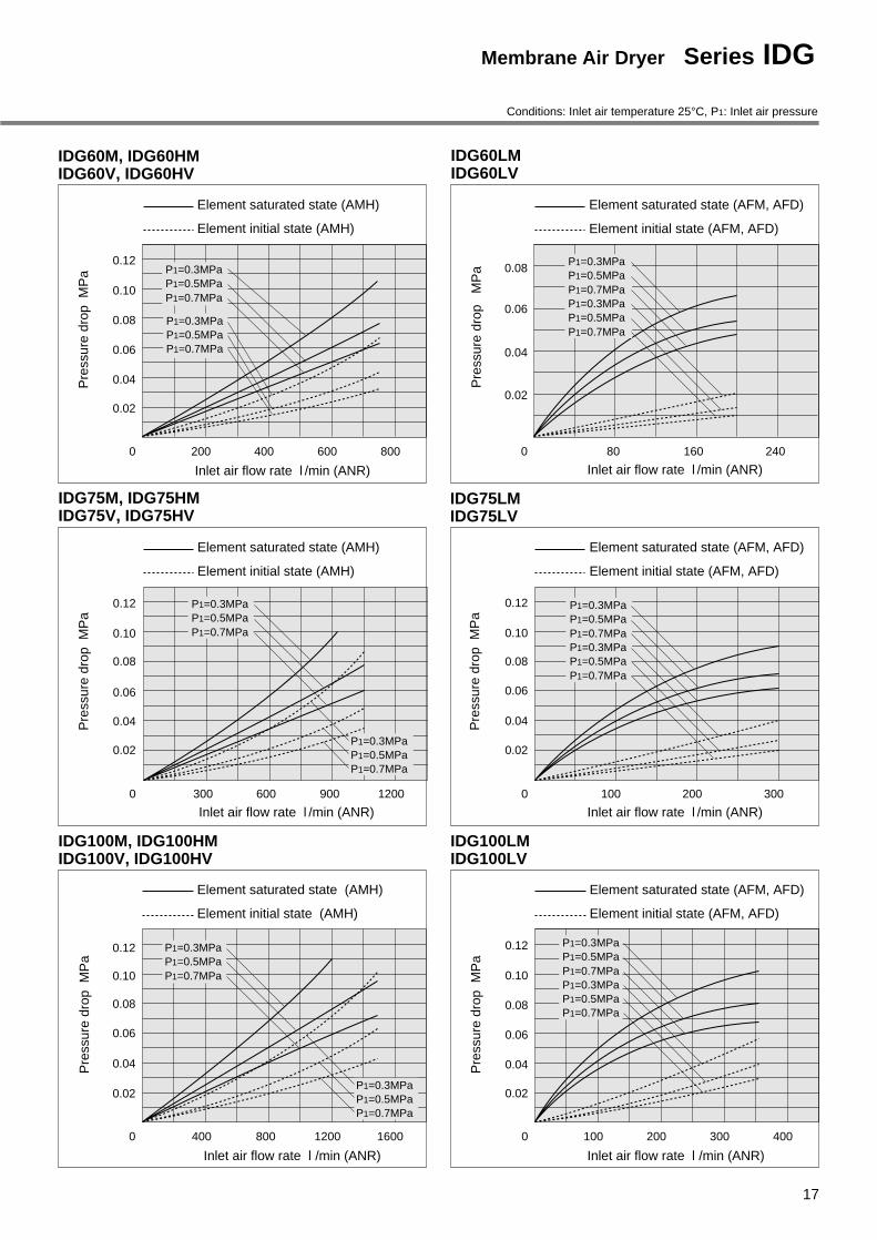
IDG60LMIDG60LV
IDG75M, IDG75HMIDG75V, IDG75HV
IDG75LMIDG75LV
Conditions: Inlet air temperature 25°C, P1: Inlet air pressure
IDG100M, IDG100HMIDG100V, IDG100HV
IDG100LMIDG100LV
Inlet air flow rate l /min (ANR)P
ress
ure
drop
M
Pa
0
0.02
0.04
0.06
0.08
Element saturated state (AFM, AFD)
Element initial state (AFM, AFD)
80 160 240
Pre
ssur
e dr
op M
Pa
0
Element saturated state (AMH)
Element initial state (AMH)
0.02
0.04
0.06
0.08
0.10
0.12
300 600 900 1200
Inlet air flow rate l /min (ANR)0 100 200 300
Element saturated state (AFM, AFD)
Element initial state (AFM, AFD)
Pre
ssur
e dr
op M
Pa
0.02
0.04
0.06
0.08
0.10
0.12
Inlet air flow rate l /min (ANR)
0
Element saturated state (AMH)
Element initial state (AMH)
Pre
ssur
e dr
op M
Pa
400 800 1200 1600
0.02
0.04
0.06
0.08
0.10
0.12
Inlet air flow rate l /min (ANR)
0
Element saturated state (AFM, AFD)
Element initial state (AFM, AFD)
Pre
ssur
e dr
op M
Pa
0.02
0.04
0.06
0.08
0.10
0.12
100 200 300 400
Inlet air flow rate l /min (ANR)
P1=0.3MPaP1=0.5MPaP1=0.7MPa
P1=0.3MPaP1=0.5MPaP1=0.7MPa
P1=0.3MPaP1=0.5MPaP1=0.7MPaP1=0.3MPaP1=0.5MPaP1=0.7MPa
P1=0.3MPaP1=0.5MPaP1=0.7MPaP1=0.3MPaP1=0.5MPaP1=0.7MPa
P1=0.3MPaP1=0.5MPaP1=0.7MPa
P1=0.3MPaP1=0.5MPaP1=0.7MPa
P1=0.3MPaP1=0.5MPaP1=0.7MPaP1=0.3MPaP1=0.5MPaP1=0.7MPa
IDG60M, IDG60HMIDG60V, IDG60HV
0
Element saturated state (AMH)
Element initial state (AMH)
Pre
ssur
e dr
op M
Pa
0.02
0.04
0.06
0.08
0.10
0.12
200 400 600 800
Inlet air flow rate l /min (ANR)
P1=0.3MPaP1=0.5MPaP1=0.7MPa
P1=0.3MPaP1=0.5MPaP1=0.7MPa
17
Membrane Air Dryer Series IDG

IDG5M, IDG5HM
Dimensions (M Type)
With fittings for purge air discharge (Option:P)
M5 x 0.8
120.
5
With differential pressure typeauto drain
Drain discharge
(196)
(73)
173
5.5
97.5
8.5
IN
Drain Drain
45
11
50
Port size: 1/8, 1/4
(Maintenance space 100mm or more)
Dew point indicator(Option: S)
OUT
118
140
Drain Drain
45
Purge air discharge tubing portfor dehumidificationApplicable tube O.D.: ø8
(177
)
(64)
120.
5
M5 x 0.8
Pur
ge a
ir fo
r de
hum
idifi
catio
n
11
IN OUT
5
924
50
30
Port size: Rc 1/8, 1/4
(NPT, PF threads not available)
Purge air discharge tubing portfor dew point indicator
Applicable tube O.D.: ø8
Dew point indicator
(Option: PS)
Series IDG
18

IDG10M, IDG10HMIDG20M, IDG20HM
ModelsOption: P
A B
211 187241 212
C D
With float typeauto drain
H
With drain guide
J238 224
170268
E810249
135
DrainDrain
7
129
1114
IDG10M, IDG10HMIDG20M, IDG20HM
(Maintenance space 100mm or more)
B
(Maintenance space 100mm or more)
Purge airfor dew point indicator
22
Purge air discharge tubing portfor dew point indicator
Applicable tube O.D.: ø8
Purge air discharge tubing portfor dehumidification
Applicable tube O.D.: øE
With fittings for purge air discharge (Option: P)
Drain Drain
(C)
11
7
59
A
59 64
(91)
170
(D)
(59)
With float type auto drain With drain guide
Applicable tube O.D.: ø10
(NPT threads: ø3/8 inch)
Thread size: 1/4(without valve mechanism)
Width across flats 17
J
H
Drain discharge
IN OUT
OUTIN
Port size1/4, 3/8
Purge air fordehumidification
Purge airfor dehumidification
7 1035
71
41
Purge air fordehumidification
Purge airfor dehumidification
Port size: Rc 1/4, 3/8(NPT, PF threads not available)
With drain guide
Rc1/4(without valve mechanism)
Width across flats 17
J
Drain discharge
19
Membrane Air Dryer Series IDG

IDG30M, IDG30HM, IDG30LMIDG50M, IDG50HM, IDG50LM
IDG30M, IDG30HM, IDG30LMIDG50M, IDG50HM, IDG50LM
ModelsOption: P
B
293337
D
With float typeauto drain
H
With drain guide
J361
206
F
18405
171
With fittings for purge air discharge (Option: P)
Port size: 1/4, 3/8
238
(Maintenance space 100mm or more)
Drain
77
165
13
IN
18
(B)
Drain9
Maintenancespace 100mm or more
Purge air for dew point indicator
OUT
22
IN OUT
Purge air discharge tubing portfor dehumidificationApplicable tube O.D.: ø12(NPT threads: ø1/2 inch)
Drain Drain
(D)
(59)
Purge air discharge tubing portfor dew point indicator
Applicable tube O.D.:ø8ø5/16 inch
F
With float type auto drain With drain guide
Applicable tube O.D.: ø10
(NPT threads: ø3/8 inch)
Thread size: 1/4(without valve mechanism)
Width across flats 17
J
H
Drain discharge
( )
Dimensions (M Type)
84
88
Purge airfor dehumidification
OUT
4010
50
Port size1/4, 3/8
Series IDG
20
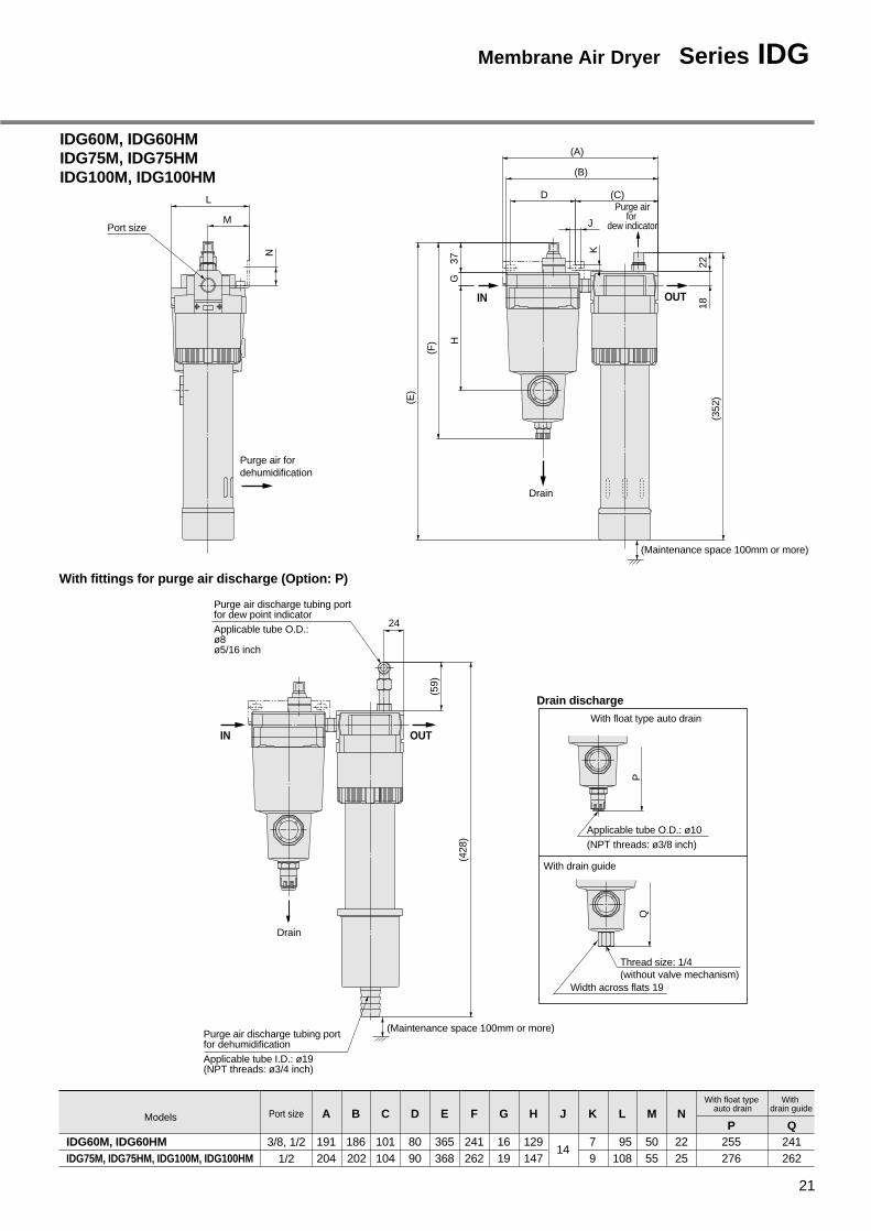
IDG60M, IDG60HMIDG75M, IDG75HMIDG100M, IDG100HM
With fittings for purge air discharge (Option: P)
Purge airfor
dew indicator
Drain
IDG60M, IDG60HMIDG75M, IDG75HM, IDG100M, IDG100HM
Models
3/8, 1/21/2
With float type auto drain
With drain guidePort size A B C D E
191 186 101 80 365204 202 104 90 368
F
241262
G
1619
H
129147
J
14
K
79
L
95108
M
5055
N
2225
P255276
Q241262
OUTIN
OUTIN
(Maintenance space 100mm or more)
(Maintenance space 100mm or more)Purge air discharge tubing portfor dehumidificationApplicable tube I.D.: ø19(NPT threads: ø3/4 inch)
(59)
(428
)
Applicable tube O.D.: ø10(NPT threads: ø3/8 inch)
P
(E)
(352
)
(F) H
G37
K
2218
24
(A)
(B)
(C)
J
D
Purge air discharge tubing portfor dew point indicatorApplicable tube O.D.:ø8ø5/16 inch
Drain
With drain guide
With float type auto drain
Drain discharge
Width across flats 19
Thread size: 1/4(without valve mechanism)
Q
Purge air fordehumidification
Port size
N
L
M
21
Membrane Air Dryer Series IDG

IDG60LMIDG75LMIDG100LM
Dimensions (M Type)
IN OUT
(Maintenance space 100mm or more)
(B)
165
1318
22
(250)
77 84
9DrainDrain
Purge airfor dew point indicator
With fittings for purge air discharge (Option: P)
IN OUT
Port size3/8, 1/2
(Maintenance space100mm or more)Applicable tube I.D.: ø19
(NPT threads: ø3/4 inch)
Purge air discharge tubing portfor dehumidification
Purge air discharge tubing portfor dew point indicatorApplicable tube O.D.:ø8ø5/16 inch
(59)
(D)
F
DrainDrain
Port size3/8, 1/2
4010
91
50
OUT
Purge air fordehumidification
With drain guide
With float type auto drain
Drain discharge
IDG60LMIDG75LM
ModelF
24IDG100LM
D468548618
B
392472542
With float typeauto drain
H
With drain guideOption: P
J
206 171
Thread size: 1/4
J
Width across flats 17
H
Applicable tube O.D: ø10(NPT threads: ø3/8 inch)
Series IDG
22

Dimensions (V Type)
IDG5V, IDG5HV
223
Dew point indicator(Option: S)
11
97.5
118
5.5
8.5
Drain Drain
45 133
IN
(Maintenance space 100mm or more)
140
124
OUT
IDG10V, IDG10HVIDG20V, IDG20HV
59 C
IN
14
Drain
129
11
Drain 7
22
A
(Maintenance space 100mm or more)
OUT
(B
)
Purge air for dew point indicator
With float type auto drain With drain guide
Applicable tube O.D.: ø10
(NPT threads: ø3/8 inch)
Thread size: 1/4(without valve mechanism)
Width across flats 17
E
D
Drain discharge
M5 x 0.8
120.
5
With differential pressuretype auto drain
Drain discharge
IDG10V, IDG10HVIDG20V, IDG20HV
Models A
275305
BWith float type
auto drain
D
With drain guide
E187
170
C
158188212
135
Pur
ge a
ir fo
r de
hum
idifi
catio
n
Port size 1/8, 1/4
965
30
24
41
Purge airfor dehumidification
Purge airfor dehumidification
3510
Port size1/4, 3/8 73
23
Membrane Air Dryer Series IDG

IDG30V, IDG30HV, IDG30LVIDG50V, IDG50HV, IDG50LV
IDG30V, IDG30HV, IDG30LVIDG50V, IDG50HV, IDG50LV
Models B
293337
With float typeauto drain
D
With drain guide
E
206 171
Purge air for dew point indicator
IN
165
13
Drain
9
Drain
77
18
168
322
22
OUT
(Maintenance space 100mm or more)
(B)
With float type auto drain With drain guide
Applicable tube O.D.: ø10
(NPT threads: ø3/8 inch)
Thread size: 1/4(without valve mechanism)
Width across flats 17
E
D
Drain discharge
Dimensions (V Type)
Purge airfor dehumidification
4010
Port size 1/4, 3/888
50
Series IDG
24
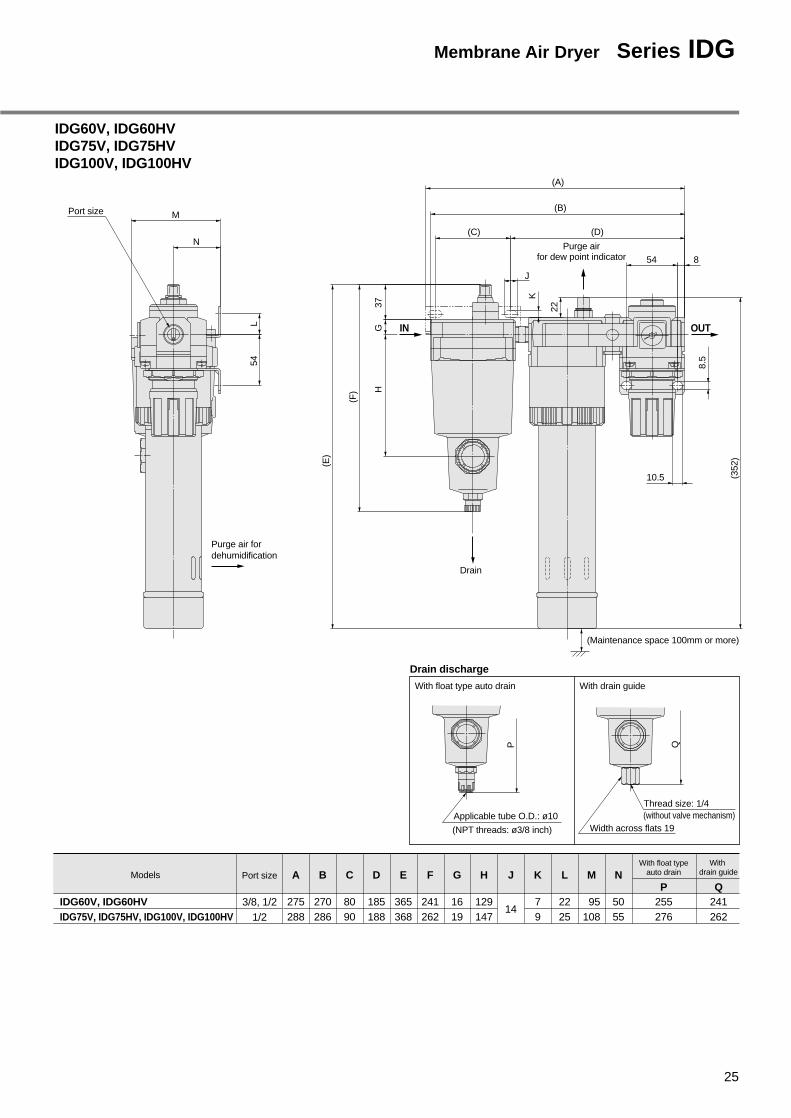
IDG60V, IDG60HVIDG75V, IDG75HVIDG100V, IDG100HV
With float type auto drain With drain guide
Drain discharge
IDG60V, IDG60HVIDG75V, IDG75HV, IDG100V, IDG100HV
Models
3/8, 1/21/2
With float typeauto drain
With drain guidePort size A B C D E
275 270 80 185 365288 286 90 188 368
F
241262
G
1619
H
129147
J
14
K
79
L
2225
M
95108
N
5055
P255276
Q241262
Purge airfor dew point indicator
(Maintenance space 100mm or more)
(352
)
K
J
Drain
(E)
(A)
8.5
8
(B)
54
(C)
IN OUTG
(F) H
10.5
22
(D)
37
Applicable tube O.D.: ø10
P
(NPT threads: ø3/8 inch)
Thread size: 1/4
Q
Width across flats 19(without valve mechanism)
Purge air fordehumidification
54L
N
MPort size
25
Membrane Air Dryer Series IDG

IDG60LVIDG75LVIDG100LV
Dimensions (V Type)
(Maintenance space 100mm or more)
77
9
165
Purge air for dewpoint indicator
(B)
334
180
IN OUT
Drain Drain
1813
22
With float type auto drain With drain guide
Drain discharge
IDG60LVIDG75LV
Model B
392472
IDG100LV 542
With float typeauto drain
H
With drain guide
J
206 171
H
Applicable tube O.D.: ø10(with NPT threads: ø3/8 inch)
Thread size: 1/4
J
Width across flats 17
Purge air fordehumidification
4010
50
91
Port size3/8, 1/2
Series IDG
26

27
Atmospheric pressure dew point temperature °C
Pre
ssur
ized
dew
poi
nt te
mpe
ratu
re °
C
0
10
20
30
40
50
60
– 60 – 50– 60
– 50
– 40 – 30
– 40
– 30
– 20
– 10
– 20 – 10 0 10 20 30
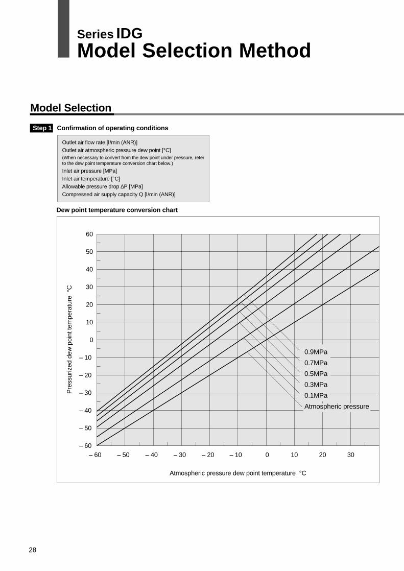
Dew point temperature conversion chart
Model Selection
Outlet air flow rate [l/min (ANR)]Outlet air atmospheric pressure dew point [°C](When necessary to convert from the dew point under pressure, refer to the dew point temperature conversion chart below.)
Inlet air pressure [MPa]Inlet air temperature [°C]Allowable pressure drop ∆P [MPa]Compressed air supply capacity Q [l/min (ANR)]
Step 1 Confirmation of operating conditions
0.9MPa
0.7MPa
0.5MPa
0.3MPa
0.1MPa
Atmospheric pressure
Series IDGModel Selection Method
28
Model Determination
or
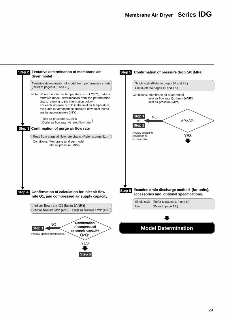
Step 5 Confirmation of pressure drop ∆P1 [MPa]
Step 5
Step 1
Step 2
Single style (Refer to pages 30 and 31.)
Unit (Refer to pages 16 and 17.)
Single style (Refer to pages 1, 4 and 6.)
Unit (Refer to page 12.)Inlet air flow rate Q1 [l/min (ANR)]=Outlet air flow rate [l/min (ANR)] + Purge air flow rate [l /min (ANR)]
Step 6
NO
YES
Step 4
Step 1NO
Review operating conditions.
YES
Confirmationof compressed
air supply capacityQ≥Q1
∆P≥∆P1
Step 3 Confirmation of purge air flow rate
Read from purge air flow rate charts (Refer to page 31.)
Conditions: Membrane air dryer model Inlet air pressure [MPa]
Step 2
Tentative determination of model from performance charts (Refer to pages 3, 5 and 7. )
Confirmation of calculation for inlet air flow rate Q1, and compressed air supply capacity
Tentative determination of membrane air dryer model
Conditions: Membrane air dryer modelInlet air flow rate Q1 [l/min (ANR)]Inlet air pressure [MPa]
Review operating conditions or increase size.
Examine drain discharge method (for units), accessories and optional specifications.
Note: When the inlet air temperature is not 25°C, make a tentative model determination from the performance charts referring to the information below.For each increase of 1°C in the inlet air temperature, the outlet air atmospheric pressure dew point increa-ses by approximately 0.8°C.
( Inlet air pressure: 0.7MPa ) Outlet air flow rate: At rated flow rate
29
Membrane Air Dryer Series IDG

IDG5, IDG5H
IDG20, IDG20H
Inlet air flow rate l/min (ANR)
Inlet air flow rate l/min (ANR) Inlet air flow rate l/min (ANR)
Pre
ssur
e dr
op M
Pa
Pre
ssur
e dr
op M
Pa
Pre
ssur
e dr
op M
Pa
Flow Rate Characteristics
IDG30, IDG30H, IDG30L IDG50, IDG50H, IDG50L
Inlet air flow rate l/min (ANR) Inlet air flow rate l/min (ANR)
Pre
ssur
e dr
op M
Pa
Pre
ssur
e dr
op M
Pa
0
0.02
0.04
0
0.01
0.02
0.03
0.04
0.06
0.08
0
20 40 80
100 200 300
100 200 300 400 500 0 200 400 600 800
0.02
0.04
0.06
0.08
60
0.01
0.02
0.03
0
0.02
0.04
0.06
40 80 120 160
P1=0.3MPa
P1=0.5MPa
P1=0.7MPa
P1=0.3MPa
P1=0.5MPa
P1=0.7MPa
P1=0.3MPa
P1=0.5MPa
P1=0.7MPa
P1=0.3MPa
P1=0.5MPa
P1=0.7MPa
P1=0.3MPa
P1=0.5MPa
P1=0.7MPa
IDG60, IDG60H
Inlet air flow rate l/min (ANR)
Pre
ssur
e dr
op M
Pa
0 200 400 600 800
0.01
0.02
0.03 P1=0.3MPa
P1=0.5MPa
P1=0.7MPa
IDG1
IDG10, IDG10H
Inlet air flow rate l/min (ANR)
Pre
ssur
e dr
op M
Pa
0
0.01
0.02
0.03
0.04
4 8 1612
P1=0.3MPa
P1=0.5MPa
P1=0.7MPa
IDG60L
Inlet air flow rate l/min (ANR)
Pre
ssur
e dr
op M
Pa
0 100 200 300
0.002
0.004
0.006
0.008
0.01
P1=0.7MPa
P1=0.5MPa
P1=0.3MPa
Series IDG
30
IDG75L
IDG100L
Inlet air flow rate l/min (ANR)
Inlet air flow rate l/min (ANR) Inlet air flow rate l/min (ANR)
Pre
ssur
e dr
op M
Pa
Pre
ssur
e dr
op M
Pa
Pre
ssur
e dr
op M
Pa
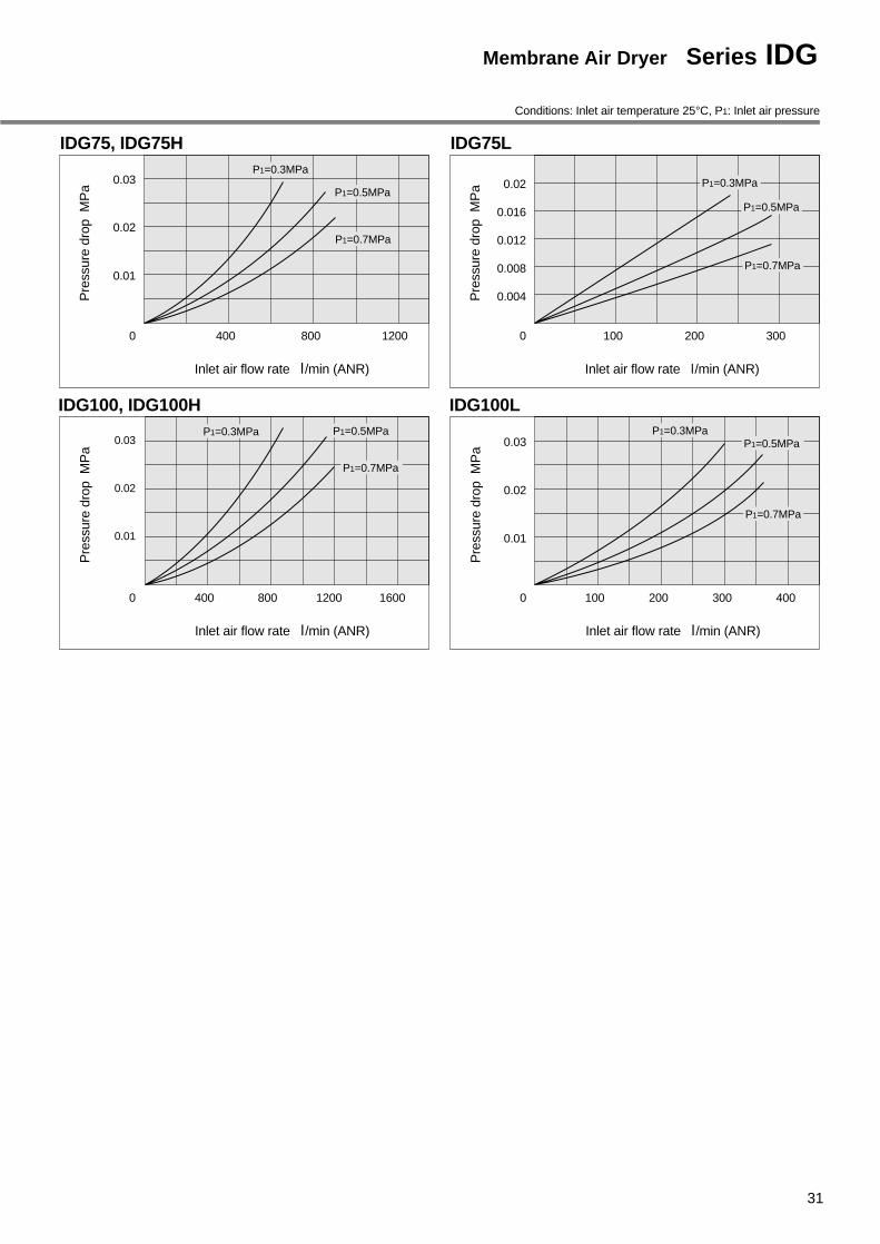
Conditions: Inlet air temperature 25°C, P1: Inlet air pressure
0
0.01
0.02
0.03
0
0.004
0.008
0.012
0.016
0.02
100 200 300
100 200 300 4000
0.01
0.02
0.03
400 800 1200 1600
IDG75, IDG75H
IDG100, IDG100H
Inlet air flow rate l/min (ANR)
Pre
ssur
e dr
op M
Pa
0
0.01
0.02
0.03
400 800 1200
P1=0.3MPa
P1=0.5MPa
P1=0.7MPa
P1=0.3MPa
P1=0.5MPa
P1=0.7MPa
P1=0.3MPa P1=0.5MPa
P1=0.7MPa
P1=0.3MPaP1=0.5MPa
P1=0.7MPa
31
Membrane Air Dryer Series IDG

Purge Air Flow Rate Charts Conditions: Inlet air temperature 25°C
Pur
ge a
ir flo
w r
ate
l/m
in (
AN
R)
40
50
60
1.0
Pur
ge a
ir flo
w r
ate
l/m
in (
AN
R)
120
140
160
180
IDG1 IDG5IDG5H
IDG10IDG10H
IDG20IDG20H
IDG30IDG30H
IDG30LIDG50
IDG50HIDG50L
0
10
20
30
Inlet air pressure MPa
0.5
Inlet air pressure MPa
40
0
20
0.5
80
60
100
1.0
IDG20 IDG50
IDG30
IDG50H
IDG50L
IDG30L
IDG30H
IDG10
IDG20H
IDG5
IDG10H
IDG5H
IDG1
Pur
ge a
ir flo
w r
ate
l/m
in (
AN
R)
240
200
160
120
80
40
280
1.0
Pur
ge a
ir flo
w r
ate
l/m
in (
AN
R)
120
140
IDG60IDG60H
IDG75IDG75H
IDG100IDG100H IDG60L IDG75L IDG100L
0
Inlet air pressure MPa
0.5
Inlet air pressure MPa
40
0
20
0.5
80
60
100
1.0
IDG100
IDG75
IDG60
IDG100H
IDG60H
IDG75H
IDG60L
IDG75L
IDG100L
Series IDG
32

33
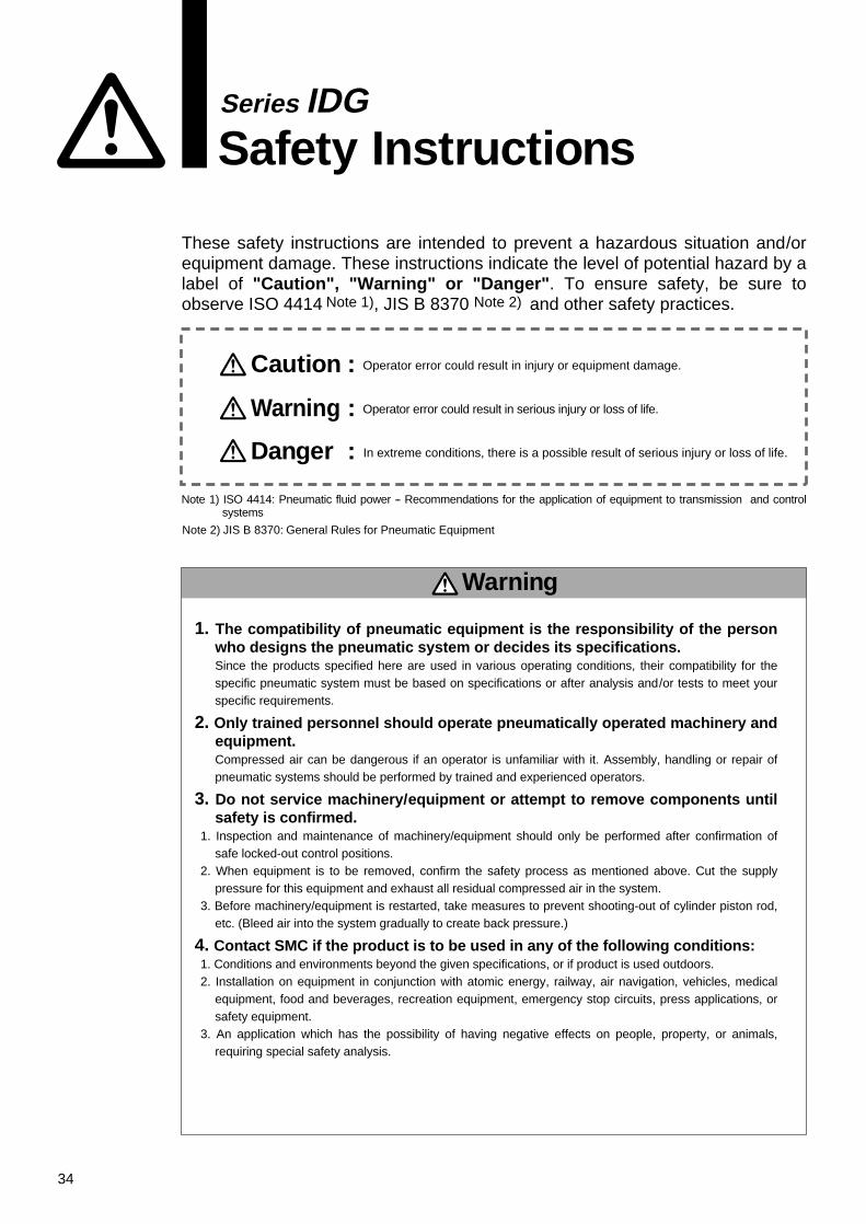
Series IDGSafety Instructions
Note 1) ISO 4414: Pneumatic fluid power -- Recommendations for the application of equipment to transmission and control systems
Note 2) JIS B 8370: General Rules for Pneumatic Equipment
Warning
Caution : Operator error could result in injury or equipment damage.
Warning : Operator error could result in serious injury or loss of life.
Danger : In extreme conditions, there is a possible result of serious injury or loss of life.
These safety instructions are intended to prevent a hazardous situation and/or equipment damage. These instructions indicate the level of potential hazard by a label of "Caution", "Warning" or "Danger". To ensure safety, be sure to observe ISO 4414 Note 1), JIS B 8370 Note 2) and other safety practices.
1. The compatibility of pneumatic equipment is the responsibility of the person who designs the pneumatic system or decides its specifications.Since the products specified here are used in various operating conditions, their compatibility for the specific pneumatic system must be based on specifications or after analysis and/or tests to meet your specific requirements.
2. Only trained personnel should operate pneumatically operated machinery and equipment.Compressed air can be dangerous if an operator is unfamiliar with it. Assembly, handling or repair of pneumatic systems should be performed by trained and experienced operators.
3. Do not service machinery/equipment or attempt to remove components until safety is confirmed.
1. Inspection and maintenance of machinery/equipment should only be performed after confirmation of safe locked-out control positions.
2. When equipment is to be removed, confirm the safety process as mentioned above. Cut the supply pressure for this equipment and exhaust all residual compressed air in the system.
3. Before machinery/equipment is restarted, take measures to prevent shooting-out of cylinder piston rod, etc. (Bleed air into the system gradually to create back pressure.)
4. Contact SMC if the product is to be used in any of the following conditions:1. Conditions and environments beyond the given specifications, or if product is used outdoors.2. Installation on equipment in conjunction with atomic energy, railway, air navigation, vehicles, medical
equipment, food and beverages, recreation equipment, emergency stop circuits, press applications, or safety equipment.
3. An application which has the possibility of having negative effects on people, property, or animals, requiring special safety analysis.
34

Employ a safe design so that the following type of unexpected conditions will not occur.
Warning1. Design so that high temperature compressed
air does not flow downstream.In case of cooling equipment failure (stoppage of cooling water in water cooled type after cooler, stoppage of fan motor in air cooled type after cooler, etc.) on the air supply side, high tem-perature compressed air can flow downstream and cause da-mage or malfunction of downstream equipment (separators, air dryers, etc.).
2. Use a design that allows for stoppage of the compressed air supply.Compressed air flow may be stopped by clogging of separators, etc.
Caution1. Use a design that prevents reverse pressure
and back flow.Reverse pressure and back flow can cause equipment damage or malfunction, etc.
Give attention to safety measures, including handling procedu-res.
Warning1. When selecting equipment, first adequately
confirm the purpose for which it will be used, the required specifications and the operating conditions (pressure, flow rate, temperature, environment), etc. Then select equipment from the latest catalogs without exceeding the specification ranges. Contact SMC in ad-vance regarding any questions.
2. Do not use for caisson shields, breathing, medical treatment or for blowing of medicine or food products which will enter the human body.This cleaning equipment is exclusively for use with industrial compressed air, and should not be used for other applications. If other application is unavoidable, give attention to safety mea-sures and contact SMC in advance.
3. This product cannot be used on board vehi-cles or vessels.This product cannot be used on board vehicles, vessels or ot-her transportation devices, because vibration will cause dama-ge. If this type of use is unavoidable, contact SMC in advance.
Caution1. Do not allow flow greater than the rated flow
rate.If the flow exceeds the rated flow rate even momentarily, this can cause drainage and oil to be sprayed into the downstream side or cause damage.
2. The product cannot be used with low pressu-re air (blowers).Cleaning equipment is exclusively for use with compressed air at a minimum operating pressure determined according to the equipment. Using below the minimum operating pressure can cause reduced performance and malfunction. If this type of use is unavoidable, contact SMC in advance.
Caution1. Confirm the mounting position.
Since the mounting position is different for each piece of equipment, this should be confirmed either in this catalog or in the instruction manual. Mounting in a tilted position can cause faulty drainage discharge, auto drain malfunction and damage in some types of equipment.
2. Ensure suffient maintenance space.When installing and mounting, be sure to allow the space requi-red for maintenance and inspections. Confirm the necessary maintenance space in the instruction manual for each piece of equipment.
Caution1. Preparation before piping
Before piping is connected, it should be thoroughly blown out with air (flushing) or washed to remove chips, cutting oil and ot-her debris from inside the pipe.
2. Wrapping of pipe tapeWhen screwing together pipes and fittings, etc., be certain that chips from the pipe threads and sealing material do not get insi-de the piping.
Further, when pipe tape is used, leave 1.5 to 2 thread ridges exposed at the end of the threads.
3. Implement measures to prevent drainage from collecting inside piping.Drains should be installed in the lower sections of piping that ri-ses, or piping should be designed with a slight taper provided along the direction of flow so that drainage will not accumulate.
4. Confirm IN and Out ports.When piping is being installed, take care to prevent incorrect connection of the water and air sides, or the IN and OUT ports.
Precautions on Design
Selection
Mounting
Piping
Selection
Series IDGAir Cleaning Equipment Precautions 1Be sure to read before handling.
35
Warning1. Do not use with fluids other than compressed
air.Cleaning equipment is designed exclusively for use with com-pressed air. Contact SMC in advance if a fluid other than com-pressed air is to be used.
2. Do not use compressed air which contains chemicals, organic solvents or corrosive gases.Do not use compressed air containing chemicals, organic sol-vents, salt or corrosive gases, as this can cause damage and/or malfunction, etc.
3. Use within the operating pressure range.The operating pressure range is determined by the equipment being used. Operation beyond this range can cause damage, failure or malfunction.
Warning1. Do not use in the following environments, as
this can cause failure.1. Locations with an atmosphere of corrosive gases, organic sol-
vents or chemical solutions, or where there may be contact with these.
2. Locations where there is contact with sea spray, water or steam.
3. Locations which receive direct sunlight. (Sunlight should be blocked to prevent deterioration of resin from ultra violet rays, and over heating, etc.)
4. Locations near heat sources with poor ventilation. (Heat sour-ces should be blocked off, because radiated heat may cause damage due to softening of materials.)
5. Locations with impacts or vibration. (Check the specifications for each series.)
6. Locations with high moisture and dust. (Contact SMC in advance.)
2. Adhere to the fluid and ambient temperature ranges.The fluid and ambient temperatures are determined by the equipment being used. Operation beyond this range can cause damage, failure or malfunction, etc.
Air Supply
Operating Environment
Warning1. If an abnormality occurs, stop the compres-
sed air.If abnormalities such as smoke, unusual odor or unusual noise occur, stop the inflow of compressed air, as this may indicate a fire.
2. When performing inspections, set the com-pressed air pressure at zero.When the compressed air side is to be disassembled for auto drain inspection, separator element replacement or film module replacement, etc., confirm that the pressure is at zero before proceeding.
Caution1. Do not place heavy objects on the unit or use
it as a step.The equipment may be deformed or damaged, and if balance is lost, falling may cause injury.
2. Discharge drainage regularly.Accumulation of drainage in equipment, piping or other areas can cause malfunction of the equipment or unexpected trouble due to splash over into the downstream side, etc. Therefore, the amount of drainage and the operation of auto drains should be checked every day.
Maintenance
Series IDGAir Cleaning Equipment Precautions 2Be sure to read before handling.
36

Precautions on Design Selection
Mounting
Caution1. Devise a layout which considers the position
of purge air discharge ports.Purge air is humid air. Devise a layout in which purge air will not cause trouble such as corrosion or malfunction of peripheral equipment.
2. When very clean air is required(supply to air bearings, blowing of semiconductor parts, etc.)
Install a micro mist separator or super mist separator on the downstream side (end terminal) of the membrane air dryer (unit).
Furthermore, grease is used in the regulator that is used in units (V type). When very clean air is required, install a separa-tor as mentioned above on the downstream side, or instead of a regulator, use a type (special order) that is fitted with a micro mist separator regulator (AWD series).
3. Time to reach the rated dew pointA certain amount of time is required to reach the rated dew point after beginning the flow of air into the membrane air dryer. Using the times below as a guide, begin operating downstream equipment after reaching the rated dew point.
Standard dew point – 20˚C, – 15˚C: Approx. 10min.
Standard dew point – 40˚C: Approx. 30 min.∗
∗ This time can be shortened as described below.
1) Provide a valve on the downstream side of the membrane air dryer.
2) Supply air with the valve closed. Only purge air flows into the membrane air dryer.
3) After 15 minutes or more, open the valve and let air flow to the downstream equipment.
4. Dehumidification performance when inlet air temperature changesThe performance charts indicate an inlet air temperature of 25˚C. See below for other temperatures.
For each increase of 1˚C in the inlet air temperature, the outlet air atmospheric pressure dew point increases by approximately 0.8˚C.
(Inlet air pressure: 0.7MPa, Outlet air flow rate: At rated flow rate)
Caution1. Consider the purge air flow rate.
Read the purge air flow rate from the charts and calculate the "required outlet air flow rate + purge air flow rate".
The air supply capacity must be at least equal to the calculated flow or the required outlet air flow rate cannot be obtained.
2. Selection on a line in which a mist separator or micro mist separator is already installedConfirm the operating air flow rate and pressure, and select a membrane air dryer in accordance with the model selection method (page 28). If a membrane air dryer is selected based on the port sizes of previously installed equipment, a model may be selected which is too small and the dehumidification capacity may be insufficient.
3. With fittings for purge air discharge (Option: P)As the length of the tubing for purge air discharge increases, dehumidification performance decreases. Use the specified tubing size and keep the length within 5 meters or less. Refer to "Outlet air atmospheric pressure dew point by purge air dischar-ge tube length" on page 3 for information on this subject.
Caution1. Do not obstruct the purge air discharge ports.
If purge air back pressure becomes too high or purge air stops flowing, dehumidification performance will decrease or become impossible.
2. Be sure to install a mist separator and micro mist separator or a micro mist separator with pre-filter on the upstream side of the mem-brane air dryer.If the inlet air contains oil or water drops, etc., performance will be reduced. (A mist separator and micro mist separator or a micro mist separator with pre-filter are already installed on the unit types.)
3. Install a regulator on the downstream side of the membrane air dryer.If it is installed on the upstream side, dehumidification perfor-mance will be reduced.
4. Use adequate care in handling.There is a danger of damage if dropped.
Series IDGSpecific Product Precautions 1Be sure to read before handling.Refer to pages 34 through 36 for safety instructions and air cleaning equipment precautions.
37
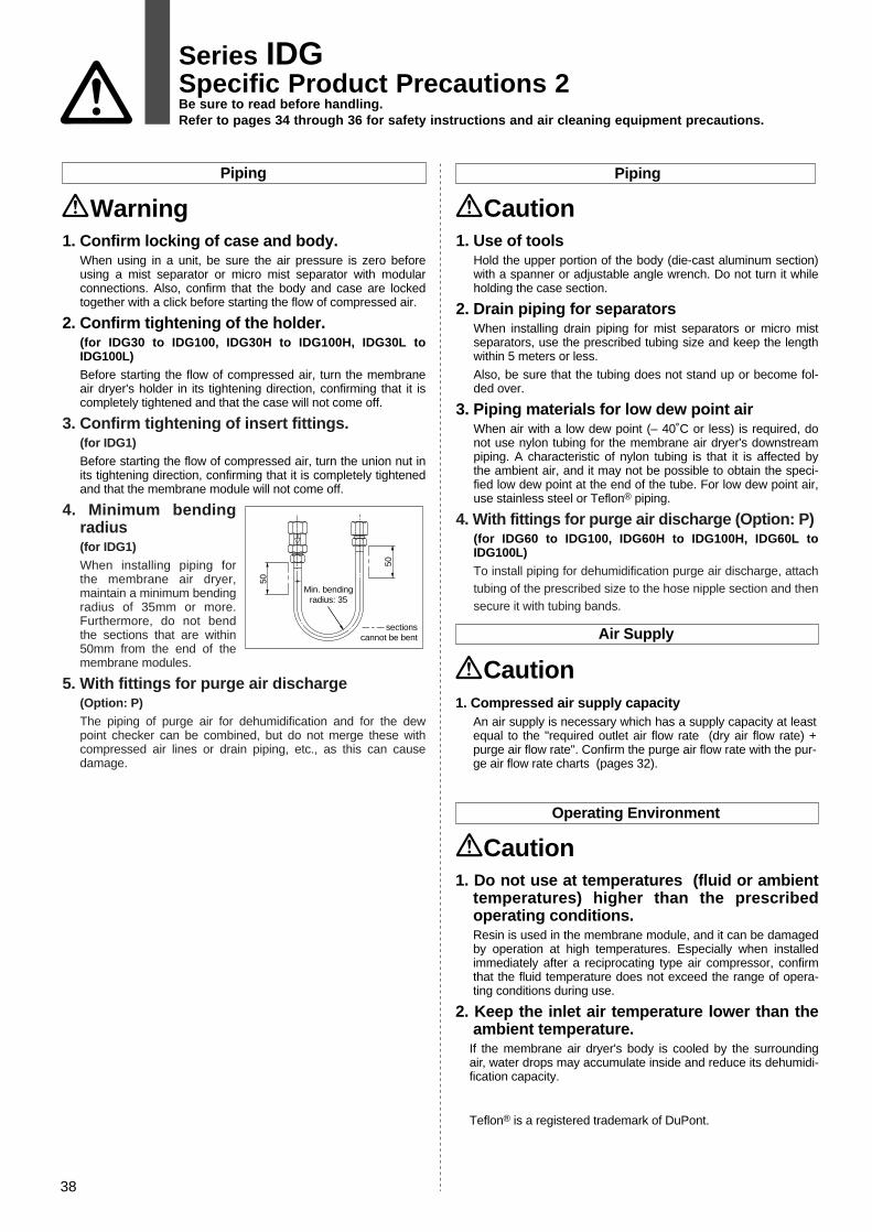
Operating Environment
Caution1. Do not use at temperatures (fluid or ambient
temperatures) higher than the prescribed operating conditions.Resin is used in the membrane module, and it can be damaged by operation at high temperatures. Especially when installed immediately after a reciprocating type air compressor, confirm that the fluid temperature does not exceed the range of opera-ting conditions during use.
2. Keep the inlet air temperature lower than the ambient temperature.
If the membrane air dryer's body is cooled by the surrounding air, water drops may accumulate inside and reduce its dehumidi-fication capacity.
Teflon® is a registered trademark of DuPont.
Air Supply
Caution1. Compressed air supply capacity
An air supply is necessary which has a supply capacity at least equal to the "required outlet air flow rate (dry air flow rate) + purge air flow rate". Confirm the purge air flow rate with the pur-ge air flow rate charts (pages 32).
Piping Piping
Caution1. Use of tools
Hold the upper portion of the body (die-cast aluminum section) with a spanner or adjustable angle wrench. Do not turn it while holding the case section.
2. Drain piping for separatorsWhen installing drain piping for mist separators or micro mist separators, use the prescribed tubing size and keep the length within 5 meters or less.
Also, be sure that the tubing does not stand up or become fol-ded over.
3. Piping materials for low dew point airWhen air with a low dew point (– 40˚C or less) is required, do not use nylon tubing for the membrane air dryer's downstream piping. A characteristic of nylon tubing is that it is affected by the ambient air, and it may not be possible to obtain the speci-fied low dew point at the end of the tube. For low dew point air, use stainless steel or Teflon® piping.
4. With fittings for purge air discharge (Option: P)(for IDG60 to IDG100, IDG60H to IDG100H, IDG60L to IDG100L)To install piping for dehumidification purge air discharge, attach tubing of the prescribed size to the hose nipple section and then secure it with tubing bands.
Warning1. Confirm locking of case and body.
When using in a unit, be sure the air pressure is zero before using a mist separator or micro mist separator with modular connections. Also, confirm that the body and case are locked together with a click before starting the flow of compressed air.
2. Confirm tightening of the holder.(for IDG30 to IDG100, IDG30H to IDG100H, IDG30L to IDG100L) Before starting the flow of compressed air, turn the membrane air dryer's holder in its tightening direction, confirming that it is completely tightened and that the case will not come off.
3. Confirm tightening of insert fittings.(for IDG1)Before starting the flow of compressed air, turn the union nut in its tightening direction, confirming that it is completely tightened and that the membrane module will not come off.
4. Minimum bending radius(for IDG1)When installing piping for the membrane air dryer, maintain a minimum bending radius of 35mm or more. Furthermore, do not bend the sections that are within 50mm from the end of the membrane modules.
5. With fittings for purge air discharge(Option: P)The piping of purge air for dehumidification and for the dew point checker can be combined, but do not merge these with compressed air lines or drain piping, etc., as this can cause damage.
50
50
Min. bendingradius: 35
sectionscannot be bent
38
Series IDGSpecific Product Precautions 2Be sure to read before handling.Refer to pages 34 through 36 for safety instructions and air cleaning equipment precautions.

Maintenance
Caution1. Confirming dehumidification function with the
dew point indicatorObserve the color of the dew point indicator to confirm whether the membrane air dryer is functioning normally.
[When dew point indicator color is blue: Functioning normally]
[When dew point indicator color is pink: Dew point temperature is high (outlet air is moist) Note: Atmospheric pressure dew point Approx. – 10˚C or more]
It takes about 1 hour from the start of air flow for the dew point indicator color to change.
2. Confirmation of oil contamination with dew point indicatorWhen the dew point indicator color turns brown, a large amount of oil has contaminated the membrane air dryer. In this case, replace the dew point indicator and membrane module.
3. Element replacement periodThe element of the mist separator and micro mist separator or micro mist separator with pre-filter, which are installed on the inlet side of the membrane air dryer, should be replaced after about two years of use.
Even within this period, replace the element if the drop in the unit's pressure reaches 0.2MPa.
4. Membrane module replacement periodReplace the membrane module if the dew point indicator's color turns white, pink or brown.
When periodic replacement is to be performed, the schedule will depend on the operating conditions, but as a general rule repla-cement should be performed after four years of use. Even within this period, replace the module if the dew point indicator's color changes to any of the colors mentioned above.
5. Tightening torque for mounting of membrane module and case(for IDG5, 10, 20, 5H, 10H, 20H)Tighten within the prescribed tightening torque range.
Tightening outside of this range can cause damage to the mem-brane module, case and mounting screws, or cause poor sea-ling, etc.
(Confirm the tightening torque range in the instruction manual.)
6. Pressure gauge installationA pressure gauge should be installed at the entry side of the membrane air dryer (unit) for maintenance and inspection purpo-ses.
Warning1. Do not remove the orifice (plug) when in a
pressurized state.Never remove the orifice (plug) while under pressure, as it can fly out causing a hazard.
39
Series IDGSpecific Product Precautions 3Be sure to read before handling.Refer to pages 34 through 36 for safety instructions and air cleaning equipment precautions.

SMC CORPORATION 1-16-4 Shimbashi, Minato-ku, Tokio 105 JAPAN; Phone:03-3502-2740 Fax:03-3508-2480
© DiskArt™ 1988
© DiskArt™ UKSMC Pneumatics (UK) LtdVincent Avenue, Crownhill,Milton Keynes, MK8 0ANPhone: 01908-563888 Fax: 01908-561185
AustriaSMC Pneumatik GmbH (Austria).Girakstrasse 8, A-2100 KorneuburgPhone: 02262-62280, Fax: 02262-62285
CzechSMC Czech.s.r.o.Kodanska 46, CZ-100 10 Prague 10Phone: 02-67154 790, Fax: 02-67154 793
PortugalSMC España (Sucursal Portugal), S.A.Rua de Engº Ferreira Dias 452, 4100 PortoPhone: 02-610-89-22, Fax: 02-610-89-36
BelgiumSMC Pneumatics N.V./S.A.Nijverheidsstraat 20, B-2160 WommelgemPhone: 03-355-1464, Fax: 03-355-1466
LithuaniaUAB Ottensten LietuvaSavanoriu pr.180, LT-2600 Vilnius, LithuaniaPhone/Fax: 370-2651602
LatviaOttensten Latvia SIACiekurkalna Prima Gara Linija 11,LV-1026 Riga, LatviaPhone: 371-23-68625, Fax: 371-75-56748
DenmarkSMC Pneumatik A/SJens Juuls vej 32, DK-8260 Viby JPhone: 45-70252900, Fax: 45-70252901
SwedenSMC Pneumatics Sweden A.B.Ekhagsvägen 29-31, S-14105 HuddingePhone: 08-603 07 00, Fax: 08-603 07 10
FranceSMC Pneumatique, S.A.1, Boulevard de Strasbourg, Parc Gustave EiffelBussy Saint GeorgesF-77607 Marne La Vallee Cedex 3Phone: 01-6476 1000, Fax: 01-6476 1010
FinlandSMC Pneumatiikka OYVeneentekijäntie 7, SF-00210 HelsinkiPhone: 09-681021, Fax: 09-6810233
EstoniaTeknoma Eesti ASMustamäe tee 5, EE-0006 Tallinn, EstoniaPhone: 259530, Fax: 259531
GreeceS. Parianopoulus S.A.9, Konstantinoupoleos Street,GR-11855 AthensPhone: 01-3426076, Fax: 01-3455578
TurkeyEntek Pnömatik San. ve Tic Ltd. Sti.Perpa Tic. Merkezi Kat: 11 No: 1625,TR-80270 Okmeydani IstanbulPhone: 0212-221-1512, Fax: 0212-220-2381
PolandSemac Co., Ltd.PL-05-075 Wesola k/Warszaway, ul. Wspolna 1APhone: 022-6131847, Fax: 022-613-3028
NetherlandsSMC Pneumatics BVPostbus 308, 1000 AH AmsterdamPhone: 020-5318888, Fax: 020-5318880
IrelandSMC Pneumatics (Ireland) Ltd.2002 Citywest Business Campus,Naas Road, Saggart, Co. DublinPhone: 01-403 9000, Fax: 01-464 0500
SpainSMC España, S.A.Zuazobidea 14, Pol. Ind. Jundiz,E-01015 VitoriaPhone: 945-184 100, Fax: 945-184 124
HungarySMC Hungary Kft.Budafoki ut 107-113, 1117 BudapestPhone: 01-204 4366, Fax: 01-204 4371
RussiaSMC Pneumatik LLCCentrako Business Centre 103,Bolshoy Prospect V.O., 199106 St. PetersburgPhone: 812-1195131, Fax: 812-1195129
SwitzerlandSMC Pneumatik AGDorfstrasse 7, CH-8484 WeisslingenPhone: 052-396-3131, Fax: 052-396-3191
ItalySMC Italia S.p.AVia Garibaldi 62, I-20061 Carugate, (Milano)Phone: 02-92711, Fax: 02-92150394
GermanySMC Pneumatik GmbHBoschring 13-15, D-63329 EgelsbachPhone: 06103-4020, Fax: 06103-402139
NorwaySMC Pneumatics (Norway) A/SWollsveien 13 C, granfoss NoeringsparkN-134 Lysaker, NorwayPhone: 22 99 6036, Fax: 22 99 6103
SloveniaSMC Slovenia d.o.o.Grajski trg 15, 8360 ZuzemberkPhone: 068-88 044 Fax: 068-88 041
SlovakiaSMC Slovakia s.r.o.Pribinova ul. C. 25, 819 02 BratislavaPhone: 0-563 3548, Fax: 07-563 3551
RomaniaSMC Romania srlVasile Stroescu 19, Sector 2, BucharestPhone: 01-210-1354 , Fax: 01-210-1680
Specifications are subject to change without prior noticeand any obligation on the part of the manufacturer.
BELFASTTel:02890 778414 Fax:02890 778422SMC Pneumatics (UK) LtdNorthern Ireland Regional CentreSuite 3, Shaftesbury House, Edgewater RoadBelfastBT3 9JQ
BIRMINGHAMTel:01675 467177 Fax:01675 465073SMC Pneumatics (UK) LtdBirmingham Regional Centre24 The Courtyard, Gorsey Lane, ColeshillWarwickshireB46 1JA
BRISTOLTel:01179 522155 Fax:01179 522186SMC Pneumatics (UK) LtdBristol Regional Centre5 East Gate Office CentreEast Gate Road, Eastville, BristolBS5 6XX
SMC UK Regional Centres
BirminghamJAMES LISTERTel: 0121 5803800Fax: 0121 5535951
BlackburnBLACKBURN PNEUMATIC SYSTEMS LTDTel: 01254 682232Fax: 01254 682224
SMC UK Distributors
CRAWLEYTel:01293 614094 Fax:01293 614135SMC Pneumatics (UK) LtdCrawley Regional Centre9 Pelham Court, Pelham Place, BroadfieldCrawleyRH11 9AZ
CUMBERNAULDTel:01236 781133 Fax:01236 780611SMC Pneumatics (UK) LtdScottish Regional Centre1 Carradale Crescent,Broadwood Business Park, CumbernauldGlasgowG68 9LE
DROITWICHTel: 01905 774544 Fax: 01905 797343SMC Pneumatics (UK) LtdDroitwich Regional CentreHampton Park, Hampton LovettDroitwich, Worcestershire WR9 0NX
IPSWICHTel:01473 240040 Fax:01473 747707SMC Pneumatics (UK) LtdIpswich Regional CentreUnit 6 & 7, Alpha Business Park16-18 Whitehouse Road, Ipswich, SuffolkIP1 5LT
MANCHESTERTel:0161 876 7371 Fax:0161 876 7372SMC Pneumatics (UK) LtdManchester Regional Centre3 Modwen Road, Waters Edge Business ParkOrdsall Lane, Salford, ManchesterM5 3EZ
MILTON KEYNESTel: 01908 265247 Fax: 01908 262705SMC Pneumatics (UK) LtdVincent Avenue, Crownhill, Milton KeynesMK8 0AN
NEWCASTLETel:0191 487 2040 Fax:0191 487 2041SMC Pneumatics (UK) LtdNewcastle Regional CentreUnit B6, Marquis Court, Marquis WayTeam Valley Trading Estate, GatesheadTyne & WearNE11 0RU
POOLETel:01202 732233 Fax:01202 737743SMC Pneumatics (UK) LtdPoole Regional CentreUnit 4, Acorn Business Centre, Ling RoadPoole, DorsetBH12 4NZ
SHEFFIELDTel: 01909 565504 Fax: 01909 569717SMC Pneumatics (UK) LtdSheffield Regional CentreUnit 4, North Anston Business ParkHoughton Road, North Anston, SheffieldS25 4JJ
BristolAPPLIED AUTOMATIONTel: 0117 9827769Fax: 0117 9235522
Bury St EdmundsPNEUMATIC LINESTel: 01284 706239Fax: 01284 761218
CardiffWALES FLUID POWERTel: 02920 494551Fax: 02920 481955
PlymouthAPPLIED AUTOMATIONTel: 01752 343300Fax: 01752 341161
ARGENTINA, AUSTRALIA, BOLIVIA, BRASIL, CANADA, CHILE, CHINA, HONG KONG, INDIA, MALAYSIA, MEXICO, NEW ZEALAND,PHILIPPINES, SINGAPORE, SOUTH KOREA, TAIWAN, THAILANDIA, USA, VENEZUELAFor more information, please contact your local SMC Regional Centre
OTHER SUBSIDIARIES WORLDWIDE:
2000/12/99


