maintenance of a vacuum. Vacuum pumps are, in gen- eral, not amenable to miniaturization, since they must possess the physical means to transport molecules from inside the system to the outside environment. The only restriction is the insistence on maintaining vacu- um, with the assumption that many samples will be analysed by the same mass spectrometer. If a miniatur- ized mass spectrometer has a total evacuated volume of 1 mL (not outside the reasonable scale), then a va- cuum reservoir of 100 mL sufRces for pumping by virtue of expansion. Essentially the vacuum is a rechar- geable resource. Removing of the vacuum hardware as a physical limitation to the size of the mass spectro- meter will be a genuine innovation in the Reld. Hope- fully, this same overview written ten years from now will document the applications of new miniaturized chromatography}mass spectrometry systems. See Colour Plate 12. Further Reading Brakstad F (1995) Chemometrics and Intelligent Laborat- ory Systems 29(2): 157}176. Cole RB (ed.) (1997) Electrospray Ionization Mass Spectro- metry: Fundamentals, Instrumentation, and Applica- tions. New York: Wiley-Interscience. Demir C and Brereton RG (1997) Calibration of gas chromatography}mass spectrometry of two-component mixtures using univariate regression and two- and three- way partial least squares. Analyst 122: 631}638. Demir C, Hindmarch R and Brereton RG (1996) Procrustes analysis for the determination of number of signiRcant masses in gas chromatography}mass spectrometry. Analyst 121: 1443}1449. Harrison AG (1992) Chemical Ionization Mass Spectro- metry, 2nd edn. Boca Raton: CRC Press. Hillenkamp F, Karas M, Beavis RC and Chair BT (1991) Matrix-assisted laser desorption/ionization mass spec- trometry of biopolymers. Analytical Chemistry 63: 1193A}1203A. Karjalainen EJ and Karjalainen UP (1996) Data Analysis for Hyphenated Techniques. Amsterdam: Elsevier Science. Martinsen DP and Song BH (1985) Mass Spectrometry Reviews 4(4): 461}490. Owens KG (1992) Applied Spectroscopy Reviews 27(1): 1}49. Smith RD, Olivares JA, Nguyen NT and Udseth HR (1998) Analytical Chemistry 40: 436}441. Vairamani M, Mirza UA and Srinivas R (1990) Mass Spec- trometry Reviews 9(2): 235}258. Van der Greef J and Niessen WMA (1992) Int. J. Mass Spectrom. Ion Proc. 118}119: 857}873. Zenobi R and Knochenmuss R (1999) Mass Spectrometry Reviews 17: 337}336. Zhang Z and McElvain JS (1999) Optimizing spectroscopic signal-to-noise ratio in analysis of data collected by a chromatographic/spectroscopic system. Analytical Chemistry 71(1): 39}45. MEMBRANE SEPARATION R. W. Baker, Membrane Technology & Research Inc. (MTR), Menlo Park, CA, USA Copyright ^ 2000 Academic Press Introduction Since the 1970s industrial membrane separation tech- nology has developed into a US$1}2 billion per year business. The market is fragmented, but can be divided into six principal industrial process areas: microRltration, ultraRltration, reverse osmosis, elec- trodialysis, gas separation and pervaporation. Dialy- sis, another membrane separation technique, is lim- ited to two biomedical processes, haemodialysis (arti- Rcial kidneys) and blood oxygenators (artiRcial lungs). The market for these two biomedical applica- tions is another US$210 9 per year. Further mem- brane separation applications, including membrane contactors, membrane reactors and coupled and facil- itated transport, are under development. Although similar membranes and membrane module designs are used in all of these process areas, the ways by which the separations are performed and the process applications are very different. A brief overview of each process is given here; more detailed descrip- tions of the individual processes are given elsewhere in the encyclopedia. History The concept of the ideal semipermeable membrane able to separate two species with the theoretical min- imum work has been used by thermodynamicists for more than 150 years, but attempts to use membranes for practical separations did not begin until the 1900s, when Bechhold devised a technique for preparing ni- trocellulose membranes of graded pore size. Later workers, particularly Zsigmondy, Bachmann, Elford and Ferry, reRned these preparative techniques and membranes were used to separate a variety of laboratory solutions by dialysis and microRltration. Sepsci*1*TSK*Venkatachala=BG I / MEMBRANE SEPARATION 189 SEPSCI=1=TSK=VVC=BG
Transcript
maintenance of a vacuum. Vacuum pumps are, in gen-eral, not amenable to miniaturization, since they mustpossess the physical means to transport moleculesfrom inside the system to the outside environment. Theonly restriction is the insistence on maintaining vacu-um, with the assumption that many samples will beanalysed by the same mass spectrometer. If a miniatur-ized mass spectrometer has a total evacuated volumeof 1 mL (not outside the reasonable scale), then a va-cuum reservoir of 100 mL sufRces for pumping byvirtue of expansion. Essentially the vacuum is a rechar-geable resource. Removing of the vacuum hardware asa physical limitation to the size of the mass spectro-meter will be a genuine innovation in the Reld. Hope-fully, this same overview written ten years from nowwill document the applications of new miniaturizedchromatography}mass spectrometry systems.
See Colour Plate 12.
Further Reading
Brakstad F (1995) Chemometrics and Intelligent Laborat-ory Systems 29(2): 157}176.
Cole RB (ed.) (1997) Electrospray Ionization Mass Spectro-metry: Fundamentals, Instrumentation, and Applica-tions. New York: Wiley-Interscience.
Demir C and Brereton RG (1997) Calibration of gaschromatography}mass spectrometry of two-component
mixtures using univariate regression and two- and three-way partial least squares. Analyst 122: 631}638.
Demir C, Hindmarch R and Brereton RG (1996) Procrustesanalysis for the determination of number of signiRcantmasses in gas chromatography}mass spectrometry.Analyst 121: 1443}1449.
Harrison AG (1992) Chemical Ionization Mass Spectro-metry, 2nd edn. Boca Raton: CRC Press.
Hillenkamp F, Karas M, Beavis RC and Chair BT (1991)Matrix-assisted laser desorption/ionization mass spec-trometry of biopolymers. Analytical Chemistry 63:1193A}1203A.
Karjalainen EJ and Karjalainen UP (1996) Data Analysis forHyphenated Techniques. Amsterdam: Elsevier Science.
Martinsen DP and Song BH (1985) Mass SpectrometryReviews 4(4): 461}490.
Owens KG (1992) Applied Spectroscopy Reviews 27(1):1}49.
Smith RD, Olivares JA, Nguyen NT and Udseth HR (1998)Analytical Chemistry 40: 436}441.
Vairamani M, Mirza UA and Srinivas R (1990) Mass Spec-trometry Reviews 9(2): 235}258.
Van der Greef J and Niessen WMA (1992) Int. J. MassSpectrom. Ion Proc. 118}119: 857}873.
Zenobi R and Knochenmuss R (1999) Mass SpectrometryReviews 17: 337}336.
Zhang Z and McElvain JS (1999) Optimizing spectroscopicsignal-to-noise ratio in analysis of data collected bya chromatographic/spectroscopic system. AnalyticalChemistry 71(1): 39}45.
MEMBRANE SEPARATION
R. W. Baker, Membrane Technology &Research Inc. (MTR), Menlo Park, CA, USA
Copyright^ 2000 Academic Press
Introduction
Since the 1970s industrial membrane separation tech-nology has developed into a US$1}2 billion per yearbusiness. The market is fragmented, but can bedivided into six principal industrial process areas:microRltration, ultraRltration, reverse osmosis, elec-trodialysis, gas separation and pervaporation. Dialy-sis, another membrane separation technique, is lim-ited to two biomedical processes, haemodialysis (arti-Rcial kidneys) and blood oxygenators (artiRciallungs). The market for these two biomedical applica-tions is another US$2�109 per year. Further mem-brane separation applications, including membranecontactors, membrane reactors and coupled and facil-itated transport, are under development. Although
similar membranes and membrane module designsare used in all of these process areas, the ways bywhich the separations are performed and the processapplications are very different. A brief overviewof each process is given here; more detailed descrip-tions of the individual processes are given elsewherein the encyclopedia.
History
The concept of the ideal semipermeable membraneable to separate two species with the theoretical min-imum work has been used by thermodynamicists formore than 150 years, but attempts to use membranesfor practical separations did not begin until the 1900s,when Bechhold devised a technique for preparing ni-trocellulose membranes of graded pore size. Laterworkers, particularly Zsigmondy, Bachmann, Elfordand Ferry, reRned these preparative techniquesand membranes were used to separate a variety oflaboratory solutions by dialysis and microRltration.
By the 1930s, microporous membranes were produc-ed commercially on a small scale. The Rrst ion ex-change membranes were made at about the sametime; these were used by Teorell, Meyer and Seiversto develop their theory of ion transport. This workled eventually to the development of electrodialysis.
By the 1960s, therefore, the elements of modernmembrane science had been developed, but mem-branes were only used in laboratories and in a fewsmall, specialized industrial applications. There wasno signiRcant membrane industry, and total sales forall applications probably did not exceed US$10 mil-lion. Membrane processes suffered from threeproblems that prohibited their widespread use: theywere too slow, too expensive and too unselective.Partial solutions to each of these problems have sincebeen developed, and sales of membranes and mem-brane separation equipment have grown several hun-dred-fold. Currently, several tens of millions ofsquare metres of membranes are produced each year,and a membrane industry has been created.
The problem of slow permeation rates throughmembranes was largely overcome in the late 1960sand early 1970s by the development of imperfection-free ultrathin membranes. These membranes are an-isotropic structures and consist of a thin selectivesurface Rlm supported by a much thicker micropor-ous substrate to provide mechanical strength. Becausethe selective surface Rlm is very thin, these mem-branes have high Suxes.
The problem of packing a large membrane areainto a low-cost module has also been solved since the1980s. The earliest module designs were plate-and-frame or tubular units similar to conventional heatexchangers. These designs are still used in some pro-cesses, such as ultraRltration, in which the ability toclean fouling deposits from the membrane surface isimportant. However, the cost of both designs is rela-tively high, and in most processes they have beendisplaced by capillary, hollow-Rne-Rbre and spiral-wound module designs.
The problem of low selectivity remains one of theprincipal limitations of membrane processes. No gen-eral solution has been found, although substantialimprovements have been made since the 1950s.
Ultrathin Membranes
The Rrst useful ultrathin membranes were celluloseacetate reverse osmosis membranes produced byLoeb and Sourirajan, two researchers at the Univer-sity of California at Los Angeles. The development ofthese thin, and hence high Sux, membranes led to thereverse osmosis industry in the 1960s. In theLoeb}Sourirajan technique, a solution containing ap-
proximately 20% polymer is cast as a thin Rlm ona nonwoven fabric web and is then precipitated byimmersion in a bath of water. The water very rapidlyprecipitates the top surface of the cast Rlm, formingthe selective skin. This skin then slows down the entryof water into the underlying polymer solution, whichprecipitates much more slowly, forming a more por-ous substructure. A scanning electron micrographshowing the porous substructure and the selectiveskin of a Loeb}Sourirajan membrane is shown inFigure 1. The selective layer thickness is typically lessthan 0.2 �m.
About one-third of the reverse osmosis and almostall ultraRltration membranes currently produced aremade by the Loeb}Sourirajan technique. This type ofmembrane is also widely used in gas separation pro-cesses.
In recent years, new approaches have been de-veloped to produce anisotropic membranes with eventhinner selective layers than those made by theLoeb}Sourirajan method. Selective layers only a fewtens of nanometers in thickness, and effectively free ofimperfections, have been claimed for these so-calledthin-Rlm composite membranes. Thin-Rlm compositemembranes can be made by a number of methods, ofwhich two are particularly important: coating witha dilute polymer solution and interfacial polymeriz-ation. In the coating method, which was developedRrst, a very dilute solution of the polymer is preparedin a volatile solvent, such as hexane. A thin Rlm ofthis polymer solution is deposited on the microporoussupport surface by immersing and then slowly with-drawing the support from the solution. As the solventevaporates, an extremely thin polymer Rlm is left be-hind. This technique is used to manufacture ultrathinmembranes for gas separation and pervaporation.
The second important method for preparing com-posite membranes is interfacial polymerization. Inthis method, an aqueous solution of a reactive mono-mer, such as a diamine, is deposited in the pores ofa microporous support membrane. The membrane isthen immersed in a water-immiscible solvent solutioncontaining a multivalent reactant, such as a triacidchloride in hexane, which causes the monomer topolymerize and cross-link. Polymerization is conRnedto the interface of the two immiscible solutions, soa thin, highly selective layer is formed. The procedureis illustrated in Figure 2. The interfacial polymeriz-ation technique is used to produce most of today’sreverse osmosis membranes.
Membrane Modules
The principal module designs } plate-and-frame, tu-bular, hollow-Rbre and spiral-wound } are illustrated
190 I / MEMBRANE SEPARATION / Derivatization
SEPSCI=1=TSK=VVC=BG
Figure 2 Preparation of ultrathin composite membranes by reaction of an amine dissolved in water and an acid chloride dissolved inhexane. The chemistry shown is widely used to prepare seawater desalination reverse osmosis membranes. (Reproduced withpermission from Roselle LT et al. (1977). In: SouriraH jan (ed.) Reverse Osmosis and Synthetic Membranes.)
Figure 1 Scanning electron micrograph of the cross-section of a Loeb}Sourirajan reverse osmosis membrane. The development ofthis type of anisotropic membrane was a critical breakthrough in the development of membrane technology.
Figure 3 Schematic of a reverse osmosis plate-and-frame module (A) and a tubular ultrafiltration membrane module (B). These twomodule designs were used in the first large industrial membrane systems but are now limited to a few niche applications.
in Figures 3 and 4. In the plate-and-frame designshown in Figure 3A a series of membrane discs separ-ated by spacers and support plates are held betweentwo end plates connected by a tension rod. The ge-ometry of the plates is such that solution entering oneend of the module passes sequentially over all themembrane area. Solution that permeates the mem-brane is collected in a permeate collection channel.Tubular modules shown in Figure 3B consist of a por-ous support tube, which is coated on the inside sur-face with the selective membrane. The porous sup-port tube nests inside steel or strong plastic tubes that
can support the applied pressure. Each tube is be-tween 0.5 and 2 cm in diameter and up to Rve tubescan be housed in a single support tube. Tubular mod-ules are now only used in ultraRltration applicationsfor which good Sow distribution across the membranesurface with no stagnant areas is required to controlmembrane fouling. In this application up to 20 tubesare connected in series as shown in Figure 3B.
Plate-and-frame and tubular membranes were wide-ly used in the early days of the modern membraneera, but by the 1980s had been largely displaced byhollow-Rbre, capillary or spiral-wound membrane
192 I / MEMBRANE SEPARATION / Derivatization
SEPSCI=1=TSK=VVC=BG
Figure 4 Schematic illustrating hollow-fibre (A) and spiral-wound (B) membrane modules. Most large-scale membrane processesuse one of the designs shown.
modules, which are much less expensive to produceper square metre of membrane area. Capillary andhollow-Rne-Rbre membranes are quite similar, dif-fering principally in the diameter of the Rbre used.Both types are produced by a spinning process muchlike conventional Rbre spinning. As a result, the costof producing the membrane per square metre is quitelow. Most of the cost of producing hollow-Rbres isincurred in the Rbre potting operation when Rbres aremounted inside the module shell. Currently, in capil-lary modules, the feed Suid circulates through the Rbrelumen (bore side) as shown in Figure 4A. In hollow-Rbre modules, the feed Suid circulates around the outersurface (shell side) of the Rbres as shown in Figure 4B.
Spiral-wound modules were originally developedfor reverse osmosis applications but are now used inultraRltration and gas separation processes aswell. This work, carried out by Fluid Systems Inc.under sponsorship of the OfRce of Saline Water
(later the OfRce of Water Research and Techno-logy), resulted in a number of spiral-wound moduledesigns. The design shown in Figure 4 is the mostcommon, consisting of a membrane envelope woundaround a perforated central collection tube. The mod-ule is placed inside a pressure vessel, and feed solutionis circulated axially down the module across the mem-brane envelope. A portion of the feed permeates intothe membrane envelope, spirals towards the centre ofthe module and exits through the collection tube.
The Sat-sheet membranes used in spiral-woundmodules usually have higher Suxes than capillary andhollow-Rbre membranes made from the samematerial. This is because it is difRcult to makehollow-Rbre selective skins as thin as Sat-sheet skins.For this reason, although spiral-wound modules areusually two to Rve times more expensive on a squaremetre basis than hollow-Rbre membranes, they arecompetitive in many applications.
Figure 5 Schematic illustrating the two principal types of mem-brane separation mechanisms. (A) Microporous membranes sep-arate by molecular filtration. (B) Dense solution-diffusion mem-branes separate because of differences in the solubility andmobility of permeant in the membrane material.
Membrane Selectivity
Improving membrane selectivity is still an area ofactive research. In some applications such as desalina-tion of water, progress has been made, and mem-branes have the required selectivity to compete withother processes such as distillation. The Rrst reverseosmosis membranes had salt rejections of approxim-ately 96}97% and could only produce potable waterfrom low concentration brackish water feeds. Thebest current membranes have salt rejections of up to99.7% and can produce potable water from sea-water. Further improvements in membrane selectivityare not required in this application.
In other applications, the low selectivity ofmembranes remains a problem. UltraRltration mem-branes, for example, cannot separate dissolvedmacromolecules, such as albumin (Mr 60 000) and�-globulin (Mr 150 000). Therefore, ultraRltration islimited to the separation of very large molecules fromvery small ones, such as macromolecules from dis-solved micro-ions. Selectivity problems also exist inelectrodialysis, gas separation and pervaporation.
Mechanism of Membrane Separation
The property of membranes used in separation pro-cesses is their ability to control the permeation ofdifferent species. Most membranes fall into oneof the two broad categories illustrated in Figure 5. Inmicroporous membranes, permeants are separated bypressure-driven Sow through tiny pores. A separationis achieved between different permeants becauseone of the permeants is excluded (Rltered) from someof the pores through which the smaller permeantsmove. In solution-diffusion membranes themembrane material is a dense polymer layer andcontains no Rxed pores. Permeants dissolve in themembrane material as in a liquid and then dif-fuse through the membrane down a concentrationgradient. Separation of different permeants oc-
curs because of differences in the solubility of thepermeant in the membrane material and the rate atwhich the permeant diffuses through the mem-brane.
The difference between the pore-Sow and thesolution-diffusion mechanisms lies in the relativesize and lifetime of pores in the membrane. In densepolymeric solution-diffusion membranes, no per-manent pores exist. However, tiny free volume ele-ments, a few tenths of a nanometre in diameter, existbetween the polymer chains from which the mem-brane is made. These free-volume elements are pres-ent as statistical Suctuations that appear and disap-pear on a timescale only slightly slower than themotion of molecules traversing the membrane. Per-meating molecules diffuse from free-volume ele-ment to free-volume element at a rate determined bythe thermal motion of the polymer chains from whichthe membrane is made. In contrast, in a pore-Sowmembrane the pores are Rxed and do not Suctuate inposition or size on the timescale of molecular motion.The larger the individual free-volume elements are,the more likely they are to be present long enough toproduce pore-Sow characteristics in the membrane.As a rule of thumb the transition between permanent(pore-Sow) and transient (solution-diffusion) poresappears to be in the range 0.5}1.0 nm diameter. Thismeans that the processes of gas separation, reverseosmosis and pervaporation, all of which involve sep-aration of permeants with molecular weights of lessthan 200, use solution-diffusion membranes. Onthe other hand, microRltration and ultraRltration,which involve separation of macromolecular or collo-idal material, use Rnely microporous pore-Sow mem-branes.
Commercial Membrane SeparationProcesses
The current status of membrane separation techno-logy is summarized in Table 1. There are seven com-mercial membrane separation processes. Of these, theRrst Rve } microRltration, ultraRltration, reverse os-mosis, electrodialysis and dialysis } are all well-estab-lished technologies with a market served by severalexperienced companies. Although incremental im-provements in membranes and membrane systems forthese technologies are expected, no major break-throughs appear imminent. The remaining two tech-nologies } gas separation and pervaporation } aredeveloping technologies for which the market size,application area, and process design are still chang-ing. Finally, several processes not shown in Table 1,including coupled and facilitated transport, mem-brane contactors and membrane reactors, are still in
194 I / MEMBRANE SEPARATION / Derivatization
SEPSCI=1=TSK=VVC=BG
Table 1 Summary of the established membrane separation technologies
Process Type ofmembrane
Materialpassed
Materialretained
Drivingforce
Status } typical application
Microfiltration Finelymicroporous0.1}10 �m
Water, dissolvedsolutes
Suspended solids,bacteria
Pressuredifference5}50 psi
Developed (&US$700 million peryear). Removal of suspended solids,bacteria in pharmaceutical, electronicsindustries
Ultrafiltration Finelymicroporous1}100 nm
Water, dissolvedsalts
Macromolecules,colloids
Pressuredifference20}100 psi
Developed (&US$150 million peryear). Removal of colloidal materialfrom wastewater, food process streams
Reverseosmosis
Densesolution-diffusion
Water Dissolved salts Pressuredifference100}1000 psi
Developed (&US$200 million peryear). Drinking water from sea, brack-ish or groundwater; production of ultra-pure water for electronics and pharma-ceutical industries
Electrodialysis Electricallycharged films
Water Ions Voltagedifference1}2 V
Developed (&US$200 million peryear). Drinking water from brackishwater; some industrial applications too
Dialysis Finelymicroporous10}100 nm
Dissolved salts,dissolved gases
Blood Concentrationdifferences
Developed (&US$1.3 billion per yearfor artificial kidney; US$500 million peryear for artificial lung)
Gas separation Dense,solution-diffusion
Permeable gasesand vapours
Impermeablegases andvapors
Pressuredifference100}1000 psi
Developing (&US$150 million peryear). Nitrogen from air, hydrogen frompetrochemical/refinery vents, carbondioxide from natural gas, propylene andVOCs from petrochemical vents
Pervaporation Dense,solution-diffusion
Permeablemicro-solutesand solvents
Impermeablemicro-solutesand solvents
Vapourpressure1}10 psi
Developing (&US$10 million per year).Dehydration of solvents (especiallyethanol)
the laboratory or early commercial stage. In the fol-lowing sections each of these membrane technologyareas is described brieSy. More detailed descriptionsof the more important processes are given elsewherein the encyclopedia.
Micro\ltration
The process MicroRltration, ultraRltration and re-verse osmosis are related membrane processes dif-fering in the size of the material retained by themembrane. As shown in Figure 6, reverse osmosismembranes can generally separate dissolved micro-solutes with a molecular weight below 500 by a solu-tion-diffusion mechanism. When the molecularweight of the solute exceeds 500, the separationmechanism of the membrane is molecular Rltration,in which separation characteristics are determined bythe size of the particles in the mixture and the dia-meter of the pores in the membrane. By convention,membranes having pore sizes up to approximately0.1 �m in diameter are considered to be ultraRltrationmembranes. MicroRltration membranes are thosewith pore diameters in the range of 0.1 to 10 �m.
Above 10 �m the separation medium is considered tobe a conventional Rlter.
UltraRltration/microRltration membranes fall intotwo broad categories: screen membrane and depthmembrane Rlters, as shown in Figure 7. Screen Rltersare anisotropic with small surface pores on a moreopen substructure. The surface pores in screen mem-brane Rlters are uniform and show a sharp cutoffbetween material that is completely retained by themembrane and material that penetrates the mem-brane. Retained material accumulates on the mem-brane surface. Depth membrane Rlters have a muchwider distribution of pore sizes and usually havea more diffuse cutoff than screen membraneRlters. Very large particulates are retained on thesurface of the membrane, but smaller particulatesentering the membrane are trapped at constrictions oradsorbed onto the membrane surface. Screen Rltersare usually used in ultraRltration applications (seenext section). The membrane pores are normally verysmall, on the order of 5}50 nm in diameter. Partic-ulates and colloidal matter retained at the membranesurface are removed by a tangential Sow of the feedsolution. In this type of process, 80}90 vol% of the
Figure 6 Pore sizes of reverse osmosis, ultrafiltration, microfiltration and conventional filtration membranes.
Figure 7 Separation of particulates can take place at the membrane surface according to a screen filtration mechanism (A) or in theinterior of the membrane by a capture mechanism as in depth filtration (B).
feed solution permeates the membrane as a cleanRltrate. The remaining solution containing the rejec-ted material is collected as a concentrated residue.
Depth Rlters are usually used in microRltrationapplications. The surface membrane pores can bequite large, on the order of 1}10 �m in diameter, butmany smaller restrictions occur in the interior of themembrane. This means that bacteria or virus particlesas small as 0.2 �m in diameter are completely pre-vented from penetrating the membrane. MicroRltra-tion membranes are usually used as an in-line Rlter.All of the feed solution is forced through the mem-brane by an applied pressure. Retained particles arecollected on or in the membrane.
The lifetime of microRltration membranes is oftenimproved by using a more open preRlter membrane
directly before the Rnal membrane. PreRlters are notabsolute Rlters, but trap most of the very large partic-ulates and many of the smaller ones before the feedsolution reaches the Rner membrane Rlter. This re-duces the particle load that the Rner membrane musthandle, and thus increases its useful life.
Applications The primary market for microRltra-tion membranes is disposable cartridges for sterileRltration of water for the pharmaceutical industryand Rnal point-of-use polishing of ultrapure water forthe electronics industry. The cost of microRltrationcompared with the value of the products is small.Cold sterilization of beer, wine and other beverages isanother emerging market area. In these processesthe microRltration cartridge removes all yeast and
196 I / MEMBRANE SEPARATION / Derivatization
SEPSCI=1=TSK=VVC=BG
Figure 8 Molecular weight cuttoff curves of various ultrafiltra-tion membranes. (Amicon Corporation trade literature.)
Figure 9 Schematic of ultrafiltration illustrating the dynamicprocess of deposition and removal of particulate and colloidalmaterial from the surface of the membrane.
bacteria from the Rltrate. This process was introduc-ed on a commercial scale in the 1960s. Although notgenerally accepted at that time, the process has be-come common in recent years.
Ultra\ltration
The process UltraRltration is intermediate betweenmicroRltration and reverse osmosis. The most reten-tive ultraRltration membrane has a substantial rejec-tion to microsolutes, such as rafRnose (Mr 504),while the most open ultraRltration membrane will bejust able to retain a molecule of relative molecularmass one million. In practice, the distinction betweenultraRltration, reverse osmosis and microRltration isvague, and it is possible to prepare membranes cover-ing the entire range of reverse osmosis, ultraRltrationand microRltration by making small changes in mem-brane preparation procedures.
Essentially all ultraRltration membranes are screenRltration membranes and separate the retained mater-ial because of the small pores in their top surface layer(see Figure 7A). Membranes are characterized bytheir molecular weight cutoff, which is usuallydeRned as the molecular weight at which the mem-brane retains more than 95% of the test solute. ThedeRnition is ambiguous, because Sexible-backboned,linear molecules can penetrate membranes more eas-ily than rigid, globular molecules, such as dissolvedproteins. In addition, despite the claims of the manu-facturers, no ultraRltration membrane has a perfectlysharp molecular weight cutoff. All membranescontain a range of pore sizes and the passage ofmolecules through the pores is completely unhinderedonly for very small molecules. Typical molecularweight cutoff curves for a series of commercialmembranes are shown in Figure 8.
UltraRltration systems generally operate at pres-sures of 20}100 psi (140}690 kPa). Osmotic pressureeffects are not signiRcant in ultraRltration, andhigh operating pressures are not required to producehigh Suxes. Moreover, because of their porous struc-ture, ultraRltration membranes compact under pres-sures above 100 psi (690 kPa).
The most important problem associated with ultra-Rltration membranes is surface fouling. The problemis illustrated in Figure 9. Material unable to passthrough the membrane accumulates at the surface,forming a solid gel-like Rlm that acts as a barrier tothe Sow of permeate through the membrane. Thethickness of the fouling Rlm is controlled by thesweeping action of the feed solution past the mem-brane surface. This circulating Sow of solutionhydrodynamically scrubs the membrane surface, con-tinuously removing the surface Rlm. Thus a balance is
achieved between circulation of solution past themembrane surface, which removes the gelled mater-ial, and the Sux of permeate through the membrane,which brings fresh material to the membrane surface.Therefore, in ultraRltration, only a portion of the feed
Figure 10 Ultrafiltration flux as a function of time for an electro-coat paint latex solution. Fouling causes flux decline in a matter ofdays. Periodic cleaning is required to maintain high fluxes.
solution permeates the membrane; the remainingsolution, containing the retained material, is removedas a concentrated residue stream.
If the feed solution circulation rate across the mem-brane surface is increased, the thickness of the foulinglayer on the membrane surface decreases, and higherpermeate Suxes through the membrane are obtained.However, at some point the increased energy costinvolved in recirculating the feed solution offsetsthe savings produced by the higher membrane Suxes.With highly fouling solutions, energy consumption of30}100 kWh per 1000 gallons (30}100 MJ m�3) ofpermeate produced is typical. The resulting electricenergy expense represents a large fraction of the oper-ating cost of an ultraRltration plant. Increasing theoperating pressure of the membrane system to forcemore permeate through the membrane is not a viablemethod of increasing the membrane Sux because thisonly produces a thicker gel layer on the membranesurface so that the Sux remains constant or evendeclines.
Even when most of the layer of deposited materialon the membrane surface is continuously removed,a portion remains and gradually densiRes. This resultsin decreased permeate Sux through the membranewith time. Periodically, ultraRltration membranemodules are cleaned by washing with a membrane-cleaning solution. This restores the Sux to almost itsoriginal value, after which the Sux begins to declineagain. The process is illustrated in Figure 10. Unfor-tunately, cleaning of badly fouled membranes doesnot completely restore the Sux to the starting value sothat a proportion of the membrane Sux is permanent-
ly lost. This permanent loss results from deposits offouling material inside the membrane, which cannotbe removed even by vigorous cleaning. The foulingmaterial gradually accumulates until even the Sux ofa freshly cleaned membrane is less than 50% of theoriginal value. At this time, the membrane is due forreplacement. A typical ultraRltration membrane life-time is 1}3 years.
Because of membrane fouling, the Sux of ultraRl-tration membranes depends highly on the composi-tion of the feed solution and the process operatingconditions. In the removal of trace particulates for thepreparation of ultrapure water, the feed solution isalready clean, and Suxes higher than 50}100 gal perft2 per day (85}170 L per m2 per day) are achieved.With more concentrated and contaminated solutions,such as food processing streams, industrial waste-waters, or electrocoat paint wastes, typical Suxes are10}30 gal per ft2 per day (17}50 L per m2 per day).
Applications UltraRltration membranes were ori-ginally developed for the laboratory market andfound an application in the concentration and desalt-ing of protein solutions. Later, Abcor and Romicondeveloped the industrial ultraRltration market. TheRrst major application was the ultraRltration of elec-trocoat paint. The process is illustrated in Figure 11.In electrocoat paint operations metal parts are im-mersed in a tank containing 15}20% of the paintemulsion. After coating, the piece is removed fromthe tank and rinsed to remove excess paint. TheultraRltration system removes ionic impurities fromthe paint tank carried over from earlier operationsand provides clean rinse water for the countercurrentrinsing operation. The concentrated paint emulsion isrecirculated back to the tank. Tubular and capillaryRbre membrane modules are generally used in theseplants because the feed solution easily fouls the mem-brane. Other large applications of ultraRltration arethe concentration of milk whey in the food industryto recover milk proteins and to remove lactose andsalts in the membrane Rltrate, and the concentrationof oil emulsions in the metal Rnishing industry. Al-though some ultraRltration plants treat industrialwaste streams, this is not a common application be-cause the process is expensive. The preparation ofultrapure water by ultraRltration for the electronicsindustry is a newer, but growing, application. Bio-technology applications are, as yet, small.
The problem of membrane fouling in ultraRltrationsystems requires expensive, energy-consuming pumpsto recirculate the feed solution. Costs of ultraRltra-tion systems are on the order of US$5}10 per1000 gal of permeate, precluding its use in large,low-value applications such as wastewater treatment.
198 I / MEMBRANE SEPARATION / Derivatization
SEPSCI=1=TSK=VVC=BG
Figure 11 Flow schematic of an electrocoat paint ultrafiltration system. The ultrafiltration system removes ionic impurities from thepaint tank carried over from the chromate/phosphate cleaning steps and provides clean rinse water for the countercurrent rinsingoperation.
Figure 12 Osmotic effects across a semipermeable membrane. (Reprinted with permission from Roper and Lightfoot (1995) Journalof Chromatography 702: 3I26, with permission from Elsevier Science.)
Therefore, ultraRltration is limited to the type ofhigh-value streams listed above. Development ofmore fouling-resistant membranes and better moduledesigns could allow wider use of the process.
Reverse Osmosis
The process The processes of osmosis and reverseosmosis are illustrated in Figure 12. In normal osmo-sis, a membrane is used to separate water from a saltsolution. If the membrane is semipermeable, that is,it allows the passage of water but does not pass salt,the small difference in water concentration (salt solu-tion) will cause water to Sow into the salt side of themembrane. This Sow will continue until the hydros-tatic pressure head on the salt solution exactly bal-ances the Sow of water across the membrane. Thisbalance is known as osmotic equilibrium. In reverse
osmosis, a pressure is applied to the salt solution thatis even higher than the osmotic pressure of the solu-tion. This applied pressure reverses the osmotic waterSow, and water Sows from the salt solution to thepure water side of the membrane. Therefore, reverseosmosis is a method of desalting saltwater solutions.Equilibrium osmotic pressures are directly propor-tional to salt concentration and are surprisinglylarge. For example, the osmotic pressure for sodiumchloride is approximately 100 psi (690kPa) for a 1%salt solution.
Two parameters affect the performance of re-verse osmosis membranes. The Rrst is the Sux or Sowper unit area per time, J, of water through the mem-brane, usually described by the equation:
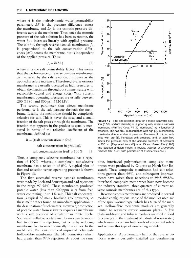
Figure 13 Flux and rejection data for a model seawater solu-tion (3.5% sodium chloride) in a good quality reverse osmosismembrane (FilmTec Corp. FT 30 membrane) as a function ofpressure. The salt flux, in accordance with eqn [2], is essentiallyconstant and independent of pressure. The water flux, in accord-ance with eqn [1], increases with pressure, and, at zero flux,meets the pressure axis at the osmotic pressure of seawater&350 psi. (Reprinted from Wijmans JG and Baker RW (1995)The solution-diffusion model: a review. Journal of MembraneScience 107: 1}21, with permission of Elsevier Science.)
where A is the hydrodynamic water permeabilityparameter, �P is the pressure difference acrossthe membrane, and �� is the osmotic pressure dif-ference across the membrane. Thus, once the osmoticpressure of the salt solution has been overcome, thewater Sux increases linearly with applied pressure.The salt Sux through reverse osmosis membranes, Js,is proportional to the salt concentration differ-ences (�C) across the membrane, but is independentof the applied pressure. Thus:
Js"B(�C) [2]
where B is the salt permeability factor. This meansthat the performance of reverse osmosis membranes,as measured by the salt rejection, improves as theapplied pressure increases. Therefore, reverse osmosismembranes are usually operated at high pressures toobtain the maximum throughput commensurate withreasonable capital and energy costs. With currentmembranes, operating pressures are usually between200 (1380) and 800 psi (5520 kPa).
The second parameter that affects membraneperformance is the salt passage through the mem-brane. Ideally, the membrane should be completelyselective for salt. This is never the case, and a smallfraction of the salt passes through the membrane. Thefraction that appears in the product is usually mea-sured in terms of the rejection coefRcient of themembrane, deRned as:
R"[(salt concentration in feed
!salt concentration in product)/
salt concentration in feed]�100% [3]
Thus, a completely selective membrane has a rejec-tion of 100%, whereas a completely nonselectivemembrane has a rejection of 0%. A typical plot ofSux and rejection versus operating pressure is shownin Figure 13.
The Rrst successful reverse osmosis membraneswere made by Loeb and Sourirajan and had rejectionsin the range 97}98%. These membranes producedpotable water (less than 500 ppm salt) from feedwater containing up to 1% salt. This salt concentra-tion is typical of many brackish groundwaters, sothese membranes found an immediate application inthe desalination of such waters. However, productionof potable water from seawater requires a membranewith a salt rejection of greater than 99%. Loeb}Sourirajan cellulose acetate membranes can be modi-Red to obtain this rejection, but only by reducingmembrane Sux to uneconomically low values. In themid-1970s, Du Pont produced improved polyamidehollow-Rbre membranes (the B10 Permeator) whichhad greater than 99% rejection. At about the same
time, interfacial polymerization composite mem-branes were produced by Cadotte at North Star Re-search. These composite membranes had salt rejec-tions greater than 99%, and subsequent improve-ments have raised these rejections to 99.5}99.8%.Interfacial composite membranes have now becomethe industry standard; three-quarters of current re-verse osmosis membranes are of this type.
Reverse osmosis membranes are produced in severalmodule conRgurations. Most of the modules used areof the spiral-wound type, which has 80% of the mar-ket. Hollow-Rbre membrane modules are generallylimited to seawater reverse osmosis plants. A fewplate-and-frame and tubular modules are used in foodprocessing and the treatment of industrial wastewater,which usually contain high levels of suspended solidsand require this type of nonfouling module.
Applications Approximately half of the reverse os-mosis systems currently installed are desalinating
200 I / MEMBRANE SEPARATION / Derivatization
SEPSCI=1=TSK=VVC=BG
Figure 14 Flow schematic of a brackish water reverse osmosis plant. The plant contains seven pressure vessels each containing sixmembrane modules. The pressure vessels are arranged in a Christmas tree array to maintain a high feed velocity through the modulesas treated water is removed in the permeate.
brackish water or seawater. Another 40% are used toproduce ultrapure water for electronics, pharmaceut-icals and power generation. The remainder are usedin small niche applications such as pollution controland food processing.
Brackish water desalination The salinity of brack-ish groundwater is usually between 1500 and5000 mg L�1. The World Health Organization rec-ommends that drinking water should contain lessthan 500 mg L�1 salt, so up to 90% of the salt mustbe removed from these waters. This is easily achievedby reverse osmosis. A typical process Sow scheme isshown in Figure 14. Frequently brackish water iscontaminated with suspended solids, so Socculation,sand Rltration, and a Rnal cartridge Rlter are used toremove these components Rrst. Adjustment of pHand addition of antiscalants may also be necessary toprevent calcium, magnesium or silica precipitating onthe membrane as water is removed and the feedbecomes more concentrated. The water may also besterilized by addition of chlorine to prevent bacterialgrowth on the membrane. Even when these elaborateand costly feed water pretreatment steps are used,some fouling of the membrane still occurs. Therefore,periodically the plant is taken off-line and themembranes are cleaned by circulating a hot cleaningsolution. Typical operating pressures for these sys-tems are in the 200}300 psig range. Plant capitalcosts are in the range US$1.00}2.00 per gal per day(plant) capacity, and operating costs are about
US$1}2 per 1000 gal of treated water produced.Well-maintained plants have useful membrane life-times of 3}5 years.
Seawater desalination Seawater contains about3.5% dissolved salt, which means membranes withsalt rejections above 99.3% are required to producepotable water. Today’s membranes can easily meetthese targets, and many seawater desalination plantsare now operating. Because of the high osmotic pres-sure of seawater (&350 psi (2415 kPa)) these plantsoperate at pressures of 800}1000 psi (5520}6900 kPa). Typical seawater reverse osmosis plantshave a capital cost of US$4}5 gal per day capacity andproduce desalted water for a cost of about US$5 per1000 gal of product. These costs mean the process ismost competitive for systems below 10 million galper day capacity. Above this range economies of scaletend to favour multi-effect evaporation plantsoften built to use the waste heat from electric powerstations.
Ultrapure water With the development of the elec-tronics industry, a large market has emerged for re-verse osmosis plants to produce ultrapure water con-taining (1 ppb total ions from water normally con-taining 50}100 ppm total ions. Typical operatingpressures for the reverse osmosis systems used in theseplants are low, on the order of 100}150 psi (690}1035 kPa). The reverse osmosis plant removes98}99% of the salts and dissolved particles in the feed
Figure 15 Schematic diagram of a plate-and-frame electrodialysis stack. Alternating cation- and anion-permeable membranes arearranged in a stack of up to 100 cell pairs.
water. Carbon adsorption and ion exchange units areused to remove the remaining contaminants.
Electrodialysis
The process Electrodialysis is a process in whichelectrically charged membranes are used to separateions from aqueous solutions under the driving forceof an electrical potential difference. The process,illustrated in Figure 15, utilizes an electrodialysisstack built on the Rlter press principle. The stackconsists of 200}400 alternate cationic and anionicmembranes between two electrodes; the aqueous feedsolution Sows through the cells between each pair ofmembranes. When an electrical potential differ-ence is applied between the two electrodes, positivelycharged cations in the feed solution move toward thecathode. These ions easily pass through the negativelycharged cation exchange membranes, but are retainedby the positively charged anion exchange membranes.Similarly, negatively charged anions migrate towardsthe anode, pass through the anion exchange mem-brane and are retained by the cation exchange mem-brane. Because of the arrangement of ion-selective
membranes, the migrating ions become concentratedin each alternate cell in the stack. Thus, ions removedfrom the aqueous feed solution are concentrated intotwo separate streams.
Applications
Brackish water Brackish water desalination is thelargest application of electrodialysis. The competitivetechnologies are ion exchange for very dilute solu-tions (below 500 ppm) and reverse osmosis for solu-tions above 2000 ppm salt. In the 500}2000 ppmrange, electrodialysis is almost always the lowest costprocess. One advantage of electrodialysis when ap-plied to brackish water desalination is that a largefraction, typically 80}95% of the brackish feed, isrecovered as potable water. However, these high re-coveries mean that the concentrated brine streamproduced is 5}20 times more concentrated than thefeed. Precipitation of insoluble salts in the brine canlimit the water recovery.
Since the Rrst electrodialysis plants were producedin the early 1950s, several thousand brackish water
202 I / MEMBRANE SEPARATION / Derivatization
SEPSCI=1=TSK=VVC=BG
Figure 16 Flow scheme of a typical electrodialysis processused in a seawater salt concentration plant.
electrodialysis plants have been installed around theworld. Modern electrodialysis units are generallyfully automated and require only periodic operatorattention. This has encouraged installation of manysmall trailer-mounted plants. However, a number ofvery large plants with production rates of 10 mil-lion gal per day or more have also been produced.
The power consumption of an electrodialysis plantis directly proportional to the salt concentration inthe feed water, and varies from 4 kWh per 1000 gal(4 MJ m�3) for 1000 ppm feed water to 10}15 kWhper 1000 gal (10}15 MJ m�3) for 5000 ppm feedwater. About one-quarter to one-third of this poweris used to drive the feed water recirculation pumps.
Seawater A second major application of elec-trodialysis is the production of table salt by concen-tration of seawater. This process is only practised inJapan, which has no other domestic salt supply. Theprocess is heavily subsidized by the government.Total production is approximately 1.2 million tonsper year of salt, with more than 500 000 m2 of mem-brane used in the plants.
A Sow scheme for one such seawater salt-produc-tion plant is shown in Figure 16. A cogenerationpower plant produces the power required for theelectrodialysis operation, which concentrates the saltin seawater to about 18}20 wt%. Waste steam from
the power plant is then used to concentrate the saltfurther by evaporation.
Gas Separation
The process The study of gas permeation throughmembranes has a long history dating back to thework of Thomas Graham in the mid-nineteenth cen-tury. However, the Rrst systematic studies with poly-mers of the type used today did not begin until 100years later.
The mechanism of gas permeation developed inthe 1950s and 1960s was the solution-diffusionmodel. In this model, the rate of diffusion through thepolymer membrane is governed by Fick’s law of diffu-sion. For simple gases, it can be shown that Fick’s lawleads to the expression
J"Dk�pl
[4]
where J is the membrane Sux (cm3(STP)/cm2 s), k isthe Henry’s law sorption coefRcient linking theconcentration of gas in the membrane material to thepressure of the adjacent gas (cm3(STP)/cm Hg), �p isthe partial difference across the membrane, l isthe membrane thickness (cm), and D is the permeantdiffusion coefRcient (cm2 s�1), a measure of thepermeant’s mobility in the membrane. This expres-sion can be further simpliRed to
J"P�pl
[5]
where P is a permeability, equal to the product Dk,and is a measure of the rate at which a particular gasmoves through the membrane of a standard thickness(1 cm) under a standard driving pressure (1 cm Hg).The permeability unit, 1�10�10 cm3 (STP) cm/cm2 s cm Hg, is called a Barrer, after R.M. Barrer,a pioneer in membrane permeation studies.
A measure of the ability of a membrane to separatetwo gases (1) and (2) is the ratio of their permeabili-ties, called the membrane selectivity, �:
�1,2"P1
P2"D1
D2�
k1
k2[6]
The factors that determine membrane permeabilitycan best be understood by considering the componentterms D and k. For simple gases, the diffusioncoefRcient tends to decrease with increasing per-meant diameter, because large molecules interactwith more segments of the polymer chains and arethus less mobile. On the other hand, the sorption
H2/N2, CO, CH4, etc. &500 units installed. Various hydrogen recovery applications in refineries, petrochemical andammonia plants
CO2/CH4 &200 units installed, some very large (5000}50 000 scfm) to separate carbon dioxide fromnatural gas
N2/air &5000 units installed, most small in the 50}500 scfm range (98}99.5% nitrogen)Organic solvent vapour/air, N2 &100 units installed. Diverse applications include gasoline vapour recovery at oil terminals,
recovery of monomers from reactor ventsH2O/air Many thousands of small modules sold for drying compressed air
Figure 17 Flow scheme of (A) a one-stage and (B) a two-stagemembrane gas separation system for the separation of carbondioxide from natural gas.
coefRcient of gases increases with the condensa-bility of the gas. Normally, the sorption coefRc-ient also correlates with molecular diameter, largermolecules being more condensable than smaller mol-ecules, and the Henry’s law sorption coefRcientincreases with increasing permeant diameter. Thus,the effect of increasing permeant size on per-meability is a balance between the opposing ef-fects of diffusion coefRcient, which decreaseswith increasing size, and solubility, which increaseswith increasing size. This balance determines theselectivity of a membrane for any pair of gases and isa function of the membrane material.
In glassy, rigid polymers such as polysulfone orpolyimides, permeant diffusion coefRcients aremost important. Therefore, these polymers preferen-tially permeate the small, noncondensable gases, hy-drogen, nitrogen and methane, over the larger, con-densable gases, propane and butane. On the otherhand, in rubbery polymer such as silicone rub-ber (polydimethylsiloxane), permeant solubility coef-Rcients are most important. Therefore, these poly-mers preferentially permeate the larger, more con-densable gases, propane and butane, over the smaller,noncondensable gases, hydrogen, nitrogen andmethane.
Applications The principal developed gas separ-ation processes are listed in Table 2. The Rrst large-scale commercial application of gas separation wasthe separation of hydrogen from nitrogen in ammo-nia purge gas streams. The process, launched in 1980by Permea, then a Division of Monsanto, was fol-lowed by a number of similar applications, suchas hydrogen/methane separation in reRnery off-gases and hydrogen/carbon monoxide adjustment inoxo-chemical synthetic plants.
Following Permea’s success, several US companiesproduced membrane systems to treat natural gasstreams, particularly to remove carbon dioxide. Thegoal is to produce a stream containing less than 2%carbon dioxide to meet the national pipeline speci-Rcations and a permeate enriched in carbon dioxide
to be Sared or reinjected into the ground. Currently,cellulose acetate is the most widely used membranematerial for this separation, but because the carbondioxide/methane selectivity of cellulose acetate isonly 15}20, two-stage systems are often required toachieve a sufRcient separation. More selectivepolyimide membranes are beginning to replace cellu-lose acetate membranes in this application. Flowschemes for a one-stage (A) and a two-stage (B) cellu-lose acetate membrane system for carbon diox-ide/natural gas separations are shown in Figure 17.The single-stage system has a low capital cost, but12.7% of the methane in the gas is lost with thecarbon dioxide. This loss becomes unacceptable forlarge systems, so a two-stage unit is used. The meth-ane loss is reduced to less than 2% but at the expenseof more membrane area and a large compressor. Themembrane process is generally best suited to relativelysmall streams in the 5}20 MMscfd range, but theeconomics of the process have slowly improved over
204 I / MEMBRANE SEPARATION / Derivatization
SEPSCI=1=TSK=VVC=BG
Figure 18 In the pervaporation process, a liquid contacts themembrane, which preferentially permeates one of the liquid com-ponents as a vapour. The vapour, enriched in the more per-meable component, is cooled and condensed, spontaneouslygenerating a vacuum that drives the process.
Figure 19 Fraction of benzene in permeate as a function offeed mixture composition for pervaporation at the reflux temper-ature of a binary benzene/cyclohexane mixture. (Reprinted withpermission from Industrial and Engineering Chemical Research22 (1983) 313. Copyright 1983 American Chemical Society.)
the years and more than 200 natural gas treatmentplants have now been installed } some quite large.
By far the largest gas separation process in currentuse is the production of nitrogen from air. The Rrstmembranes used for this process were based on poly-sulfone, poly(trimethylpentane) and ethyl cellulose.These polymer materials had oxygen/nitrogen selec-tivities of 4 to 5, and the economics of the processwere marginal. The second-generation materials nowused have selectivities in the range 6 to 7. With thesemembranes, the economics of nitrogen productionfrom air are very favourable, especially for smallplants producing 50}500 scfm of nitrogen; 5000 ofthese small systems are now in operation. In thisrange, membranes are the low-cost process, and mostnew nitrogen plants use membrane systems.
A growing application of membrane systems is theremoval of condensable organic vapours from air andother streams. Unlike the process described above,organic vapour separation uses rubbery membranes,which are more permeable to the organic vapour.More than 100 organic vapour recovery plants havebeen installed. In Europe, most of the plants recovergasoline vapours from air vented during transfer op-erations; in the USA, most plants recover chlorinatedand Suorinated hydrocarbons from refrigeration orchemical processing streams. Separation of propylenefrom nitrogen in polyoleRn plants is an emergingapplication worldwide.
Pervaporation
The process Pervaporation is a membrane processused to separate liquid mixtures. The feed liquidcontacts one side of a membrane, which selectivelypermeates one of the feed components, as shown inFigure 18. The permeate, enriched in this component,is removed as a vapour from the other side ofthe membrane. The driving force for the process isthe low vapour pressure on the permeate side of themembrane, which is generated by cooling and con-densing the permeate vapour. The separationachieved is proportional to the differences inrates of permeation of the components of the mixturethrough the membrane.
Pervaporation offers the possibility of separat-ing solutions, mixtures of components with closeboiling points, or azeotropes that are difRcult toseparate by distillation or other means. An illustra-tion of the ability of pervaporation membranes tobreak azeotropes is shown in Figure 19 for the separ-ation of benzene/cyclohexane mixtures. The va-pour}liquid equilibrium for the mixture shows thatbenzene/cyclohexane mixtures form an azeotrope atapproximately 50% benzene. Distillation is unable to
separate a feed stream of this composition. However,pervaporation treatment of this mixture producesa vapour permeate containing more than 95%benzene.
The Rrst systematic work on pervaporation wasdone by Binning and co-workers at American Oil inthe 1950s. The process was not commercialized atthat time and remained a mild academic curiosityuntil 1982, when GFT (Gesellschaft fuK r Trenntechnik
Figure 20 Flow scheme of an integrated distillation/pervaporation plant for ethanol recovery from fermentors.
GmbH, Germany) installed the Rrst commercial per-vaporation plant. That plant separated water fromconcentrated alcohol solutions; GFT has since instal-led more than 50 such plants. The ethanol feed to themembrane generally contains &10% water. Thepervaporation process removes the water as the per-meate, producing pure ethanol with less than 1%water, and avoiding all the problems of azeotropicdistillation.
Spurred on by this success, a great deal of ef-fort is being made to apply pervaporation to otherdifRcult separations. Exxon, for example, pur-sued the separation of hydrocarbon mixtures contain-ing aromatics and aliphatics, a major separationproblem in reRneries. Another application is the sep-aration of dissolved volatile organic compounds(VOCs) from water, developed by Membrane Tech-nology and Research, Inc.
Applications To date, the largest application of per-vaporation is the dehydration of ethanol or iso-propanol. This process has been pioneered by GFT,now a division of Sulzar, using polyvinyl alcoholcomposite membranes that are far more permeable towater than alcohol. A Sow scheme of a GFT plantcombining distillation and pervaporation to producedry alcohol is shown in Figure 20. The distillationcolumn produces an ethanol overhead stream con-taining 85}90% ethanol which is fed to the per-vaporation system. To maximize the vapour pressuredriving force across the membrane the pervaporationmodule usually operates at a temperature of105}1303C, corresponding to a need stream vapourpressure of 2}6 atm. The permeate vapour is cooledand condensed at 0 to !103C. The permeate con-tains 40}50% ethanol which is recycled to the distil-lation column; the residue stream is better than99.5 wt% ethanol. Most of the installed solvent de-
hydration systems have been for ethanol dehydration,but applications to other solvents, including iso-propanol, glycols, acetone and methylene chloride,have also been studied.
The only other commercial pervaporation applica-tion is the separation of dissolved VOCs from water.Relatively hydrophobic composite membranes, suchas silicone rubber coated on a microporous polyimidesupport membrane, are used. Extremely high separ-ation factors can be obtained for the more hydropho-bic VOCs such as toluene, benzene, chlorinatedsolvents, esters and ethers. Frequently the VOC in thecondensed permeate is enriched 100- to 1000-foldover the feed. Target applications include removal ofVOCs from industrial wastewater streams and therecovery of volatile Savour and aroma componentsin the food processing industry. The GC traces inFigure 21 illustrate the concentration and recovery oforange juice Savours from the water evaporated fromorange juice obtained by pervaporation.
The current commercial pervaporation processesinvolve the separation of organics and water. Thisseparation is relatively easy, because organic solventsand water have very different polarity and ex-hibit distinct membrane permeation properties. Nocommercial pervaporation systems have yet been de-veloped for the separation of organic/organic mix-tures. However, current technology now makes de-velopment of pervaporation for these applicationspossible, and the process is being actively developedby a number of companies. The Rrst pilot-plantresults for an organic}organic application } theseparation of methanol from methyl t-butylether/isobutene mixtures } was reported by Separexin 1988. This is a particularly favourable application,and available cellulose acetate membranes achievea good separation. More recently, Exxon starteda pervaporation pilot plant for the separation of
206 I / MEMBRANE SEPARATION / Derivatization
SEPSCI=1=TSK=VVC=BG
Figure 21 HPLC traces showing recovery of flavour and aromacomponents from orange juice evaporation condensate by per-vaporation.
Figure 22 The separation of sodium hydroxide from hemicel-lulose by dialysis. This separation became important in the pro-duction of rayon in the 1930s and 1940s. Figure 23 Schematic of a hollow-fibre haemodialyser.
aromatic/aliphatic mixtures, using polyimide/poly-urethane block copolymer membranes.
Dialysis
The process Dialysis was the Rrst membrane pro-cess to be used on an industrial scale with the devel-opment of the Cerini dialyser in Italy. The productionof rayon from cellulose expanded rapidly in the1930s, and a need arose to recover sodium hydroxidefrom hemicellulose/sodium hydroxide solution by-product streams formed in the process. A Rnelymicroporous membrane was used to separate the con-centrated hemicellulose solution from water. Thesmaller sodium hydroxide molecules diffuseacross the membrane down a concentration gradientto produce an uncontaminated product stream, asshown in Figure 22.
With the development of ultraRltration and micro-Rltration membranes in the 1960s and 1970s, indus-trial applications of dialysis largely disappeared be-cause dialysis membranes were slow and unselectivecompared to the newer technologies. However, in themedical area, two very large applications have been
developed, namely the dialysis of blood} haemodialysis } in the artiRcial kidney, and therelated process used to exchange oxygen and carbondioxide in blood in the artiRcial lung. Both processesuse the low-pressure, mild conditions of dialysis.
Applications
Haemodialysis (artiTcial kidney) The kidney isa key component in the body’s waste disposal andacid}base regulation mechanism. Approximately 1 inevery 10 000 persons will suffer irreversible kid-ney failure, which before 1960 was invariably fatal.Now a number of treatments, of which haemodialysisis by far the most important, can maintain thesepatients. As many as 800 000 patients worldwide aretreated by haemodialysis devices. Each patient is di-alysed two to three times per week with a dialyserthat contains about one square metre of membranearea. Economies of scale allow the membrane mod-ules to be produced at about US$15 each. The devicesare generally disposed of after one or two uses. Asa result the market is about US$1.3�109 per year,making this the largest membrane separation processin terms of sales per year and membrane area used.
The Rrst successful artiRcial kidney was construc-ted by Kolf and Berk in Holland in 1945. Over thenext 20 years Kolf and others developed a number ofimproved devices, and by the 1960s the process beganto be widely used. Early dialysers used coiled tubes orplate-and-frame designs. The development of hollow-Rbre dialysers reduced costs considerably, makingwidespread use of the process possible. Each Rbredialyser contains 0.5}2.0 m2 of membrane formed asRbres 0.1}0.2 mm in diameter. A typical dialysermodule (Figure 23) contains several thousand Rbresin a 2 in (5 cm) diameter tube 1}2 ft (30}60 cm)long. Blood Sows down the bore of the Rbre, and anisotonic saline solution is circulated around theoutside. Urea, creatinin and other metabolites inthe blood diffuse through the membrane to thedialysate solution. The process must be carried out
Figure 24 Schematic examples of (A) facilitated and (B)coupled transport of gas and ions. The facilitated transportexample shows the transport of oxygen across a membrane usinghaemoglobin as the carrier. The coupled transport exampleshows the transport of copper ions across the membrane usinga liquid ion exchange reagent as the carrier.
slowly to avoid shock to the patient; typically 2}4 hare required to eliminate all of the accumulatedtoxins.
Blood oxygenators (artiTcial lungs) Blood oxygen-ators are used during heart surgery. Until the early1980s direct oxygenation of blood was used to main-tain patients during surgery. Rotating discs or smallcountercurrent contacting towers delivered oxygen tothe blood and removed carbon dioxide. This proced-ure required a large volume of blood to prime theunits and damaged the blood during long surgeries.The introduction of hollow-Rbre membrane contac-tors largely solved both of these problems and wasone reason for the dramatic expansion of open-heartsurgery in the 1980s. Currently, about one millionprocedures are performed annually world-wide.A successful heart-lung must normally deliver about250 cm3(STP) per min of oxygen and remove about200 cm3(STP) per min of carbon dioxide. Micropor-ous polyoleRn hollow-Rbre membrane moduleswith a membrane area of 2}10 m2 are generallyused.
Other Membrane SeparationProcesses
The seven processes described above represent themajority of commercial membrane separation tech-nologies. However, a number of processes are still inthe laboratory or early commercial stage and may yetbecome important. These processes are describedbrieSy below.
Carrier-Assisted Transport
Carrier-assisted transport usually employs liquidmembranes containing a complexing or carrier agent.The carrier agent reacts with one permeating com-ponent on the feed side of the membrane and thendiffuses across the membrane to release the per-meant on the product side of the membrane. Thecarrier agent is then reformed and diffuses backto the feed side of the membrane. Thus, the carrieragent acts as a shuttle to transport selectively onecomponent from the feed to the product side of themembrane.
Facilitated transport membranes can be used toseparate gases; membrane transport is then driven bya difference in the gas partial pressure across themembrane. In the example shown in Figure 24, thecarrier is haemoglobin, used to transport oxygen. Onthe upstream side of the membrane, haemoglobinreacts with oxygen to form oxyhaemoglobin, whichthen diffuses to the downstream membrane in-
terface. There, the reaction is reversed } oxygen isliberated to the permeate gas and haemoglobin isreformed. The haemoglobin then diffuses backto the feed side of the membrane to pick up moreoxygen. In this process haemoglobin acts as theshuttle, transporting oxygen selectively through themembrane. Other gases, such as nitrogen, which donot react with the carrier, are left behind.
Coupled transport is similar to facilitated transportand also incorporates a carrier agent in the mem-brane. However, in coupled transport the carrieragent couples the Sow of two species. Because of thiscoupling, one of the species can be moved against itsconcentration gradient, provided the concentrationgradient of the second coupled species is sufR-ciently large. In the example shown in Figure 24, thecarrier is an oxime that forms an organic-solublecomplex with copper ions. The reaction is reversed byhydrogen ions. On the feed side of the membrane,two oxime carrier molecules pick up a copper ion,liberating two hydrogen ions to the feed solution.The copper}oxime complex then diffuses to thedownstream membrane interface, where the reactionis reversed because of the higher concentration ofhydrogen ions in the permeate solution. The copperion is liberated to the permeate solution and two
208 I / MEMBRANE SEPARATION / Derivatization
SEPSCI=1=TSK=VVC=BG
Figure 25 Schematic of a membrane reactor to separatebutadiene from n-butane.
Figure 26 Schematic showing application of a membrane con-tactor to remove dissolved oxygen from water. This process isused to prepare power plant boiler feed water.
hydrogen ions are picked up. The reformed oximemolecules diffuse back to the feed side of themembrane. Metal ions can also be selectively trans-ported across a membrane, driven by a Sow of hydro-gen or hydroxyl ions in the other direction.
Because the facilitated and active transport pro-cesses employ a reactive carrier species, very highmembrane selectivities can be achieved } often farlarger than those achieved by other membrane pro-cesses. This has maintained interest in facilitatedtransport since the 1980s, yet no signiRcant commer-cial applications exist or are likely to exist in theimmediate future. The principal limitations arethe physical instability of the liquid membrane andthe chemical instability of the carrier agent.
Membrane Reactors
In membrane reactors, the membrane is used to shifta chemical equilibrium or separate the products ofa reaction. A wide variety of processes have beensuggested, and a few have reached the commercialstage. A simple example is shown in Figure 25 } thereaction of n-butane to butadiene and hydrogen:C4H10 � C4H6#2H2.
This is an equilibrium reaction and in a conven-tional process a mixture of components is withdrawnfrom the reactor, separated, and the unreacted n-butane recirculated to the feed. In the membranereactor, hydrogen is removed through the membraneso that the chemical equilibrium in the reactor isshifted to the right and the conversion of n-butane tobutadiene is increased. Essentially pure butadieneleaves the reactor. This type of process is the subjectof a considerable research effort, mostly usingceramic membranes operating at high temperatures.The development of these devices for the productionof syngas (a mixture of carbon monoxide and hydro-gen) is the focus of very large research programmes atAir Products and Standard Oil. Promising resultshave been obtained in the laboratory, but scale-up toan economical process is still far off.
Membrane Contactors
In the membrane separation processes discussed sofar, the membrane acts as a selective barrier allowing
relatively free passage of one component while retain-ing another. In membrane contactors the membranefunction is to provide an interface between twophases but not to control the rate of passage of per-meants across the membrane. An example of thistechnology, in which the membrane is used in a pro-cess to deoxygenate water, is shown in Figure 26.
A hollow-Rbre microporous membrane separatesthe oxygen-containing water from the nitrogen sweepgas. Even though the dissolved oxygen concentrationin the water is very low, its equilibrium concentrationin the gas phase in contact with the water is severalthousand times higher. This means that oxygen per-meation through the membrane down the concentra-tion gradient to the nitrogen sweep gas is high. Themembrane provides a large surface contact area be-tween the water and nitrogen sweep gas but does notaffect the relative permeabilities of oxygen andwater vapour through the membrane. In this type ofapplication, the membrane serves as a contactor orphase separator. Exactly the same separation couldbe achieved by running the water and nitrogencountercurrent to each other in a packed tower, butmembrane contactors are much more compact. Mem-brane contactors are typically shell- and tube-devicescontaining microporous capillary hollow-Rbre mem-branes. The membrane pores are made sufR-ciently small that capillary forces prevent direct mix-ing of the two phases on either side of the membrane.
A small market has already developed for mem-brane contactors to degas ultrapure water for theelectronics industry and boiler feed water for power
1 This article does not deal with the important particle separ-ation techniques of filtration, flotation and the use of membraneswhich are dealt with elsewhere in the Encyclopedia.
plants. The long-term goal of the process is to replacepacked towers in conventional absorber}stripperoperations. Practical problems related to membranefouling and lifetime are the principal limitations.
The Future
Since the 1970s there has been a period of very rapidgrowth for the membrane separation industry. Totalsales for all membrane applications have grown ap-proximately 400-fold to the US$3}4�109 per yearlevel. In the areas of microRltration, ultraRltration,reverse osmosis, electrodialysis and dialysis, the tech-nology is relatively mature. SigniRcant growth is stilloccurring, however, as membranes continue to dis-place more conventional separation techniques. Themost rapidly expanding area is gas separation, whichhas grown to a US$150�106 per year business in justa few years. Gas separation is poised to grow a fur-ther two- or three-fold as the technology is used morewidely in the reRnery, petrochemical and natural gasprocessing areas. If the development of ceramic oxy-gen-permeable membranes for syngas membrane re-actors is successful, a membrane process that couldchange the basis of the chemical industry would thenbe available.
Further Reading
Amjad Z (1993) Reverse Osmosis. New York: Van Nos-trand-Reinhold.
Baker RW, Cussler EL, Eykamp W et al. (1991) MembraneSeparation Systems. Park Ridge, NJ: Noyes Data Corp.
Bakish R (ed.) (1991) Proceedings of the InternationalConference on Pervaporation Processes in the ChemicalIndustry, Heidelburg. Englewood, NJ: Bakish MaterialsCorp.
Bakish R (ed.) (1992) Proceedings of the InternationalConference on Pervaporation Processes in the ChemicalIndustry, Ottawa. Englewood, NJ: Bakish MaterialsCorp.
Bakish R (ed.) (1995) Proceedings of the International Co-nference on Pervaporation Processes in the Chemical In-dustry, Reno, NV. Englewood, NJ: Bakish Materials Corp.
Brock TD (1983) Membrane Filtration. Madison, WI: Sci.Tech. Inc.
Cheryan M (1986) UltraTltration Handbook. Lancaster,PA: Tecnomic Pub. Company.
Crespo JG and BoK ddeker KW (eds) (1994) Membrane Pro-cesses in Separation and PuriTcation. Dordrecht:Kluwer Academic.
Ho WS and Sirkar KK (eds) (1992) Membrane Handbook.ew York: Van Nostrand Reinhold.
Mulder M (1991) Basic Principles of Membrane Techno-logy. Dordrecht: Kluwer Academic.
Paul DR and Yampol’skii YP (eds) (1994) Polymeric GasSeparation Membranes. Boca Raton, FL: CRC Press.
Porter MC (ed.) (1990) Handbook of Industrial MembraneTechnology. Park Ridge, NJ: Noyes Publications.
Rautenbach R and Albrecht R (1989) Membrane Processes,Chichester: John Wiley & Sons.
Toshima N (ed.) (1992) Polymers for Gas Separation. NewYork: VCH.
PARTICLE SIZE SEPARATIONS
J. Janc\ a, Universite& de La Rochelle, La Rochelle,France
Copyright^ 2000 Academic Press
Historical Development
In 1556, an extraordinary book entitled De Re Metal-lica, Libri XII appeared in Basel. The author wasa German physician, naturalist and mineralogist, call-ing himself Georgius Agricola (originally calledGeorg Bauer), living in JaH chymov, Bohemia, from1494 to 1555. Agricola described, in a fascinatingmanner, the contemporary advances in metals and
minerals recovery and gave us a very detailed reporton the sophisticated technologies of his epoch. Thislate medieval period saw a true expansion of scienceand technology in Europe. Winston Churchill oncesaid: ‘2from this date, 1492, a new era in the historyof mankind takes its beginning’. As many metal re-covery processes used at that time were based onvarious separations of particulate matter and De ReMetallica, Libri XII seems to be the Rrst printedreview of separation technologies, it is Rtting to ac-knowledge Agricola’s publication priority in this Reldand to consider his book as the beginning of a modernscientiRc approach to particle size separations.
The reproduction of a rendering in Figure 1 takenfrom Agricola’s book shows a surprisingly sophisti-cated device for gold (and other metals) recovery by‘panning’ or ‘sluicing’ which used gravity and
210 I / PARTICLE SIZE SEPARATIONS / Derivatization