25
1 MEMS and NEMS Raj Nagarajan, Ph.D. Professor Electronics and Advanced Technologies Austin Community College
| Date post: | 30-Nov-2015 |
| Category: |
Documents |
| Upload: | prasanthmct |
| View: | 420 times |
| Download: | 20 times |
1
MEMS and NEMS
Raj Nagarajan, Ph.D.
Professor
Electronics and Advanced Technologies
Austin Community College
2
Objective
The objective of the module is to introduce micro- and nano -electromechanical systems to two year community college students with special emphasis on the development, processing, applications, and materials that are currently in use to produce MEMS/NEMS.
3
Topics
• Introduction• Brief History• Electromechanical Systems• MEMS• Current Applications• NEMS and Nanotechnology• Impact of Miniaturization• Challenges and Possibilities• References
4
Introduction
Figure 5.1: Jonathan Swift.
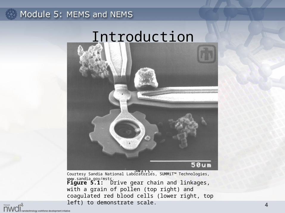
Courtesy Sandia National Laboratories, SUMMiT™ Technologies, www.sandia.gov/mstc.
Figure 5.1: Drive gear chain and linkages, with a grain of pollen (top right) and coagulated red blood cells (lower right, top left) to demonstrate scale.
5
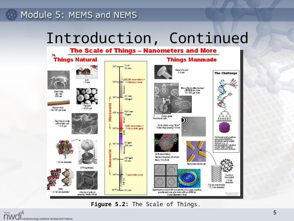
Figure 5.2: The Scale of Things.
Introduction, Continued
6
• MST - Microsystems Technology (European)
• MEMS - Microelectromechanical Systems (U.S.)
– Manmade devices created using compatible microfabrication techniques that are capable of
• Converting physical stimuli, events and parameters to electrical, mechanical & optical signals
• Performing actuation, sensing and other functions
Introduction, ContinuedDefinition and Terms
7
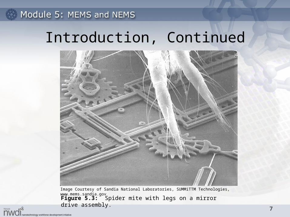
Figure 5.3: Spider mite with legs on a mirror drive assembly.
Introduction, Continued
Image Courtesy of Sandia National Laboratories, SUMMiTTM Technologies, www.mems.sandia.gov
8
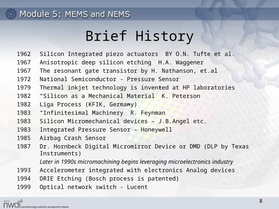
1962 Silicon Integrated piezo actuators BY O.N. Tufte et al.
1967 Anisotropic deep silicon etching H.A. Waggener
1967 The resonant gate transistor by H. Nathanson, et.al
1972 National Semiconductor - Pressure Sensor
1979 Thermal inkjet technology is invented at HP laboratories
1982 “Silicon as a Mechanical Material” K. Peterson
1982 Liga Process (KFIK, Germany)
1983 “Infinitesimal Machinery” R. Feynman
1983 Silicon Micromechanical devices – J.B.Angel etc.
1983 Integrated Pressure Sensor – Honeywell
1985 Airbag Crash Sensor
1987 Dr. Hornbeck Digital Micromirror Device or DMD (DLP by Texas Instruments)
Later in 1990s micromachining begins leveraging microelectronics industry
1993 Accelerometer integrated with electronics Analog devices
1994 DRIE Etching (Bosch process is patented)
1999 Optical network switch - Lucent
Brief History
9
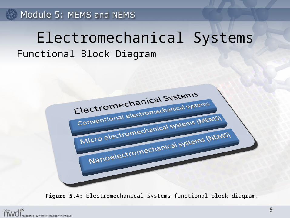
Figure 5.4: Electromechanical Systems functional block diagram.
Electromechanical SystemsFunctional Block Diagram
10
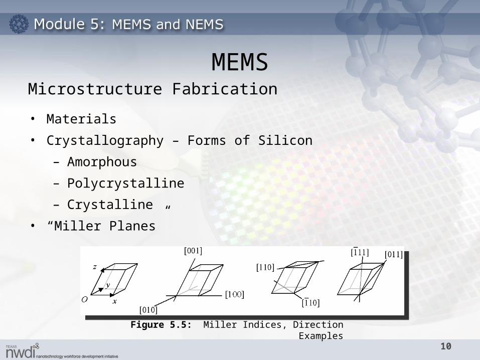
• Materials
• Crystallography – Forms of Silicon
– Amorphous
– Polycrystalline
– Crystalline
• “Miller Planes”
Figure 5.5: Miller Indices, Direction Examples
MEMSMicrostructure Fabrication
11
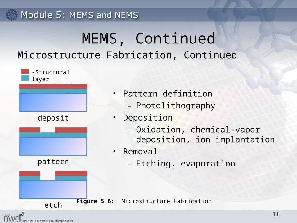
• Pattern definition– Photolithography
• Deposition– Oxidation, chemical-vapor deposition,
ion implantation• Removal
– Etching, evaporation
-Structural layer-Sacrificial layer
deposit
pattern
etchFigure 5.6: Microstructure Fabrication
MEMS, ContinuedMicrostructure Fabrication, Continued
12
MEMS, Continued
Processing Techniques• Deep Reactive Ion Etching (DRIE)
• Surface Micromachining
• LIGA process – Lithography / Electroplating / Molding
• SUMMIT process
Microstructure Fabrication, Continued
13
MEMS Advantages
The advantages of MEMS devices include
• Size
• High sensitivity
• Low noise
• Reduced cost
• Batch Processing
The applications for MEMS are so far reaching that a multi-billion dollar market is forecast. Key industry applications include transportation, telecommunications and healthcare.
MEMS, Continued
14
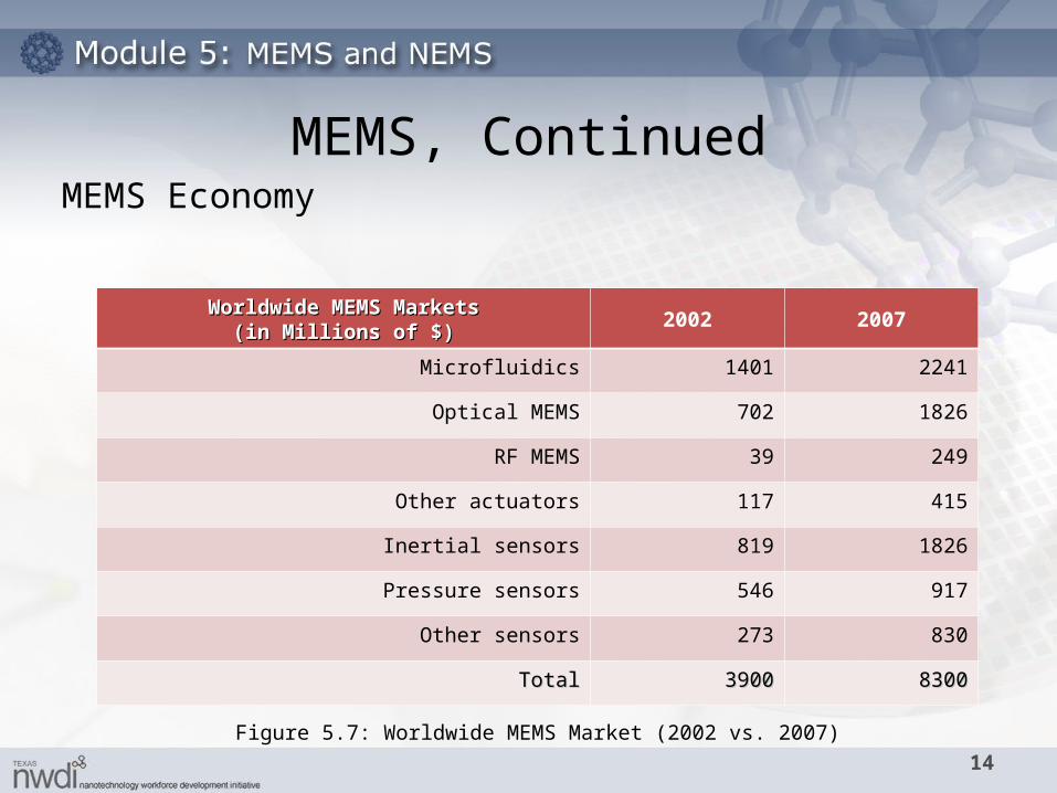
Worldwide MEMS MarketsWorldwide MEMS Markets(in Millions of $)(in Millions of $)
2002 2007
Microfluidics 1401 2241
Optical MEMS 702 1826
RF MEMS 39 249
Other actuators 117 415
Inertial sensors 819 1826
Pressure sensors 546 917
Other sensors 273 830
TotalTotal 39003900 83008300
Figure 5.7: Worldwide MEMS Market (2002 vs. 2007)
MEMS Economy
MEMS, Continued
15
• Accelerometers
• Micro Optical Electro Mechanical Systems (MOEMS)
– Digital Mirror Devices (DMD) used in Projection Devices
– Deformable mirrors
– Optical Switches
• Inkjet Print heads (Microfluidics)
• Pressure Sensors
• Gyrometers
• Magnetic RW heads for hard drives
• Seismic Activities - Thermal transfer
Current Applications
16
• Micro-arrayed biosensors
• Virus detection
• DNA Chip PCR (Polymerase Chain Reaction)
• Neuron probes (nerve damage/repair)
• Retina/Cochlear Implants
• Micro Needles
• ChemLab
• Micro Fluidic Pumps
- Insulin Pump (drug delivery)
Biomedical
Current Applications, Continued
17
• Hand held detectors – biological & chemical microsensors
– Chem’s Lab on a Chip (security applications)
• Micro and Radio Frequency (RF) Switches
• RFID Technologies
– Modern “bar-coding” system increasingly used on toll roads and materials handling applications
• Data Storage Systems
– IBM Millipede storage system – AFM tip writes data bit by melting a depression into polymer mediaum and reads data by sensing depressions.
Detection systems
Current Applications, Continued
18
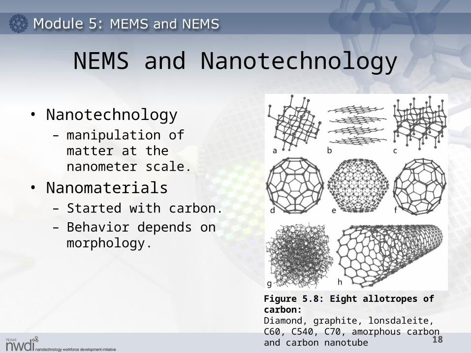
• Nanotechnology– manipulation of matter at the
nanometer scale.
• Nanomaterials– Started with carbon.– Behavior depends on
morphology.
Figure 5.8: Eight allotropes of carbon:Diamond, graphite, lonsdaleite, C60, C540, C70, amorphous carbon and carbon nanotube
NEMS and Nanotechnology
19
• Quantum dots
• Nanowires
• Quantum films
Figure 5.9: Quantum Dots.
NEMS and Nanotechnology, Continued
20
• Electrostatic manipulation
• Moving one electron or molecule at a time
• Patterning
• Dip Pen Lithography
• Electron Beam Lithography
• Self assembly
Nano Fabrication
NEMS and Nanotechnology, Continued
21
• Cantilever Sensors
• Mass Storage – (IBM) Millipede chip– Nanochip
• Molecular Electronics– Transistors– Memory cells– Nanowires – Nanoswitches
Merging of technologies
NEMS and Nanotechnology, Continued
22
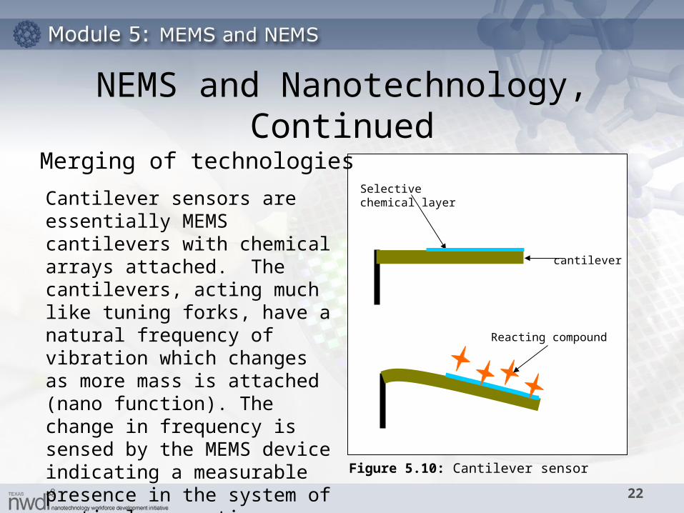
Cantilever sensors are essentially MEMS cantilevers with chemical arrays attached. The cantilevers, acting much like tuning forks, have a natural frequency of vibration which changes as more mass is attached (nano function). The change in frequency is sensed by the MEMS device indicating a measurable presence in the system of particular reacting compound.
Selective chemical layer
Reacting compound
cantilever
Figure 5.10: Cantilever sensor
Merging of technologies
NEMS and Nanotechnology, Continued
23
• Potential Positive Impacts– Reduction of disease.– Job opportunities in new fields.– Low-cost energy.– Cost reductions with improved efficiencies.– Improved product and building materials.– Transportation improvements
• Potential Negative Impacts– Material toxicity– Non-biodegradable materials.– Unanticipated consequences.– Job losses due to increased manufacturing efficiencies.
Impact of Miniaturization
24
• Fundamental and applied research
• Engineering and technological developments
• High Fidelity Modeling
• High Yield / Low Cost Fabrication
• “Molecular manufacturing”
Challenges and Possibilities
25
References
• Gad-el-Hak, M. MEMS, Design and Fabrication, Second Edition. (2005)
• Lyshevski, S., MEMS and NEMS, CRC Press LLC. (2002) • Maluf, N. and Williams, K., An Introduction to Micromechanical
Systems Engineering, Second Edition, Artechouse, Inc. (2004)• Microsytems, Same-Tec 2005 Preconference Workshop, July 25
&26, 2005.• Taylor and Francis, MEMS Introductory Course, Sandia National
Laboratories, June 13-15, 2006.• What is MEMS technology? MEMS and Nanotechnology
Clearinghouse. http://www.memsnet.org/mems/what-is.html.


