MEng Team Project UAS Challenge - 2015 Written By: Alfred Dzadey, Jonathan Ebhota, Zuber Khan, Tarek Kherbouche, Amit Ramji, Mozammel, Mohammed Mohinuddin, Micky Ngouani, Malwenna Malwenna , Hassan Turabi, Osman Sibanda, Mohammed Rayad Ullah Project Supervisor: Ray Wilkinson, Joanna Rawska, Kate Williams, Steve lines
Transcript
MEng Team Project UAS Challenge - 2015
Written By:
Alfred Dzadey, Jonathan Ebhota, Zuber Khan, Tarek Kherbouche, Amit Ramji, Mozammel, Mohammed Mohinuddin, Micky Ngouani, Malwenna Malwenna , Hassan Turabi, Osman Sibanda, Mohammed Rayad
Ullah
Project Supervisor:
Ray Wilkinson, Joanna Rawska, Kate Williams, Steve lines
UAS CHALLENGE 2015
i ACKNOWLEDGEMENTS MEng Team Project Report (7ENT1024) School of Engineering and Technology
ACKNOWLEDGEMENTS We (UAS Challenge MEng Group) would like to thank the supervisors who gave us their support and unconditional attention throughout the course of the project with weekly group meetings and off the clock advice. Their expertise in the subject helped in the successful delivery of this project. Other notable mentions are to the technicians; Chris Childs and Andrew Curl whose expertise, skill and experience were invaluable in the manufacture of the components of the UAS. We would also like to thank Gordon Banks from Ensinger for supplying the materials use for the project at a discounted prize and very swiftly too; Howard Ash for his assistance in the procurement of materials and components; Yigeng Xu for giving the MEng group permission to use E131B for assembly and testing purposes; Clive Borhem for giving technical assistance to the Propulsion Engineer and also everyone who supported the group directly and indirectly.
UAS CHALLENGE 2015
ii TABLE OF CONTENTS MEng Team Project Report (7ENT1024) School of Engineering and Technology
TABLE OF CONTENTS ACKNOWLEDGEMENTS ............................................................................................... i TABLE OF CONTENTS ................................................................................................ ii LIST OF FIGURES ...................................................................................................... vii GLOSSARY ................................................................................................................ xii 1 Introduction ........................................................................................................... 1
2.2 Further analysis ............................................................................................... 3 3 Project Management ............................................................................................ 4
3.1 Role of the Project Manager ............................................................................ 4 3.2 The Team Structure ......................................................................................... 4 3.3 Project Planning .............................................................................................. 5
3.3.1 Milestones ................................................................................................. 7 3.4 Leadership ...................................................................................................... 7 3.5 Team Communication ..................................................................................... 9 3.6 Project Budgeting ............................................................................................ 9
3.6.1 Summary of Project Budget .....................................................................10 3.6.2 Source of Funding ....................................................................................10
7.1 Load Case Definition and Free Body Diagrams ..............................................18 8 UAV Stress Analysis ............................................................................................20
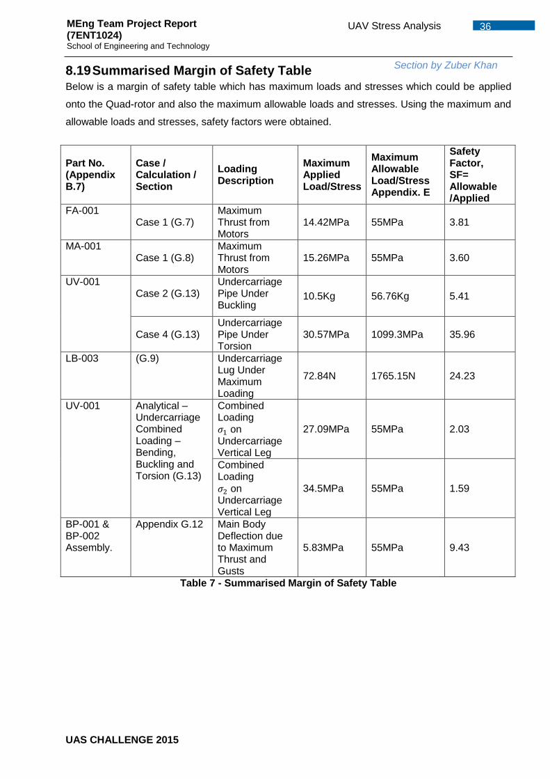
8.1 Stress Reduction Techniques .........................................................................20 8.2 Fatigue Awareness .........................................................................................20 8.3 Fatigue due to induced vibration .....................................................................21 8.4 Pressure Loading on Plates ............................................................................21 8.5 Load Transfer .................................................................................................22 8.6 Fixed and Movable Arm Stress Maximum ......................................................22 8.7 Simplified Plate Deflection ..............................................................................24
8.8 Plate Deflection - Assembly Contact Model as Built........................................27 8.9 Undercarriage Buckling Calculation ................................................................27 8.10 Undercarriage Bending ...............................................................................27 8.11 Undercarriage Bending - Assembly Contact Model .....................................28 8.12 Undercarriage Torsion .................................................................................29 8.13 Undercarriage Combined Loading - Torsion and Bending ...........................29 8.14 Undercarriage Combined Loading - Assembly Contact Model .....................30
UAS CHALLENGE 2015
iii TABLE OF CONTENTS MEng Team Project Report (7ENT1024) School of Engineering and Technology
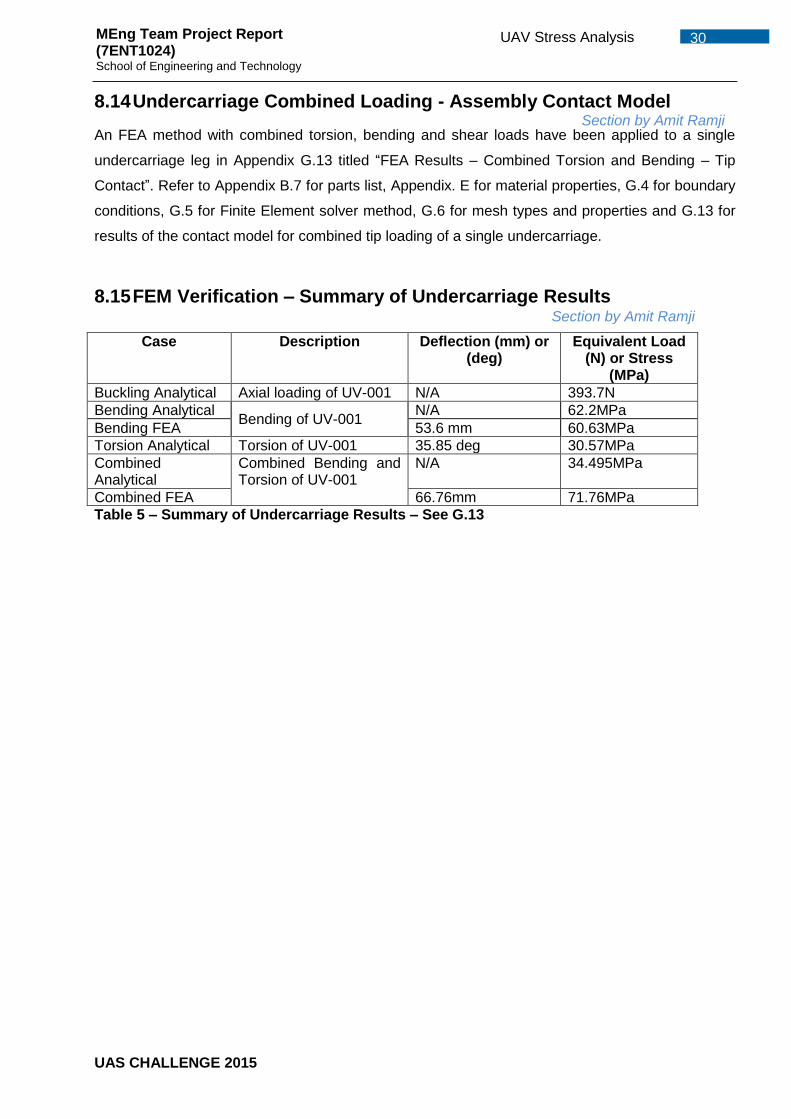
8.15 FEM Verification – Summary of Undercarriage Results ...............................30 8.16 Modal Analysis of Fixed-arm – Simplified Case ...........................................31
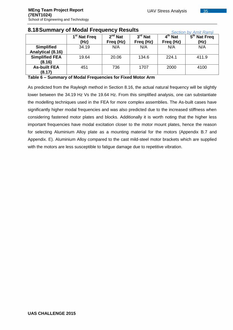
8.17 Modal Analysis of Fixed-arm – Actual Parts (As Built) .................................34 8.18 Summary of Modal Frequency Results ........................................................35 8.19 Summarised Margin of Safety Table ...........................................................36
9 Performance, Propulsion & Systems Engineer ....................................................37 9.1 Propeller Diameter Selection ..........................................................................38 9.2 RC Motor Selection Maximum RPM ...............................................................40 9.3 Propeller Pitch Selection ................................................................................41 9.4 Power Supply Voltage Selection .....................................................................43 9.5 Power Supply Capacity Selection ...................................................................44 9.6 RC Motor Selection Power .............................................................................44 9.7 Electronic Speed Controller Selection.............................................................45
10.2.1 Potential Issues with the Navigation systems ........................................47 10.2.2 Solutions ...............................................................................................47
10.3 Mission Control System ...............................................................................47 10.4 Flight Control System ..................................................................................48 10.5 Communication System ..............................................................................50
10.5.1 Serial Connection .................................................................................51 10.5.2 Telemetry Kit Connection ......................................................................51 10.5.3 Radio Connection .................................................................................52
10.6 Systems Integration.....................................................................................52 10.6.1 Communications Systems Test .............................................................52 10.6.2 Interference test ....................................................................................52 10.6.3 Range Test and Altitude Test ................................................................53 10.6.4 Post Manufacture and Assembly Design Checks ..................................53 10.6.5 Post Assembly Control System Calibration ...........................................54
11 Stability and Control I...........................................................................................55 11.1 PID Tuning ..................................................................................................56
11.1.1 Loiter mode ...........................................................................................56 11.1.2 Altitude Hold Mode (AltHold) .................................................................57
11.2 Verifying the performance of PID values .....................................................58 12 Safety Case .........................................................................................................59
13.3 Infrastructure ...............................................................................................63 13.4 Disposal of Material .....................................................................................63
14 Stability and Control II..........................................................................................65 14.1 Ideal CG location .........................................................................................65
15 Flight modes and tuning .....................................................................................66 15.1 Simulink model ............................................................................................66
UAS CHALLENGE 2015
iv TABLE OF CONTENTS MEng Team Project Report (7ENT1024) School of Engineering and Technology
15.2 Test rig PID Testing.....................................................................................68 15.2.1 Pitch and Roll tuning .............................................................................69 15.2.2 Yaw tuning ............................................................................................71 15.2.3 Waypoint navigation tuning ...................................................................71
15.3 Tuning during flight ......................................................................................72 15.4 Future Work ................................................................................................72
16 Flight Termination Case .......................................................................................73 16.1 GPS Loss ....................................................................................................73 16.2 Communication loss from Ground Station ...................................................73 16.3 Geofence Breach ........................................................................................74 16.4 Maximum Pressure Altitude Breach ............................................................74
17 Systems Layout ...................................................................................................75 17.1 System block diagram .................................................................................75
17.1.1 Hardware Systems................................................................................75 17.1.2 Software Systems .................................................................................76
17.2 Communication ...........................................................................................78 18 Image Processing ................................................................................................79
18.2 Video ...........................................................................................................81 18.3 On Screen Display Board (OSD) .................................................................82 18.4 Video transmitter .........................................................................................82 18.5 Video Receiver ............................................................................................82
20 Future work .........................................................................................................84 20.1 Partial control of Quad-rotor positioning ......................................................84 20.2 Full Autonomy .............................................................................................84
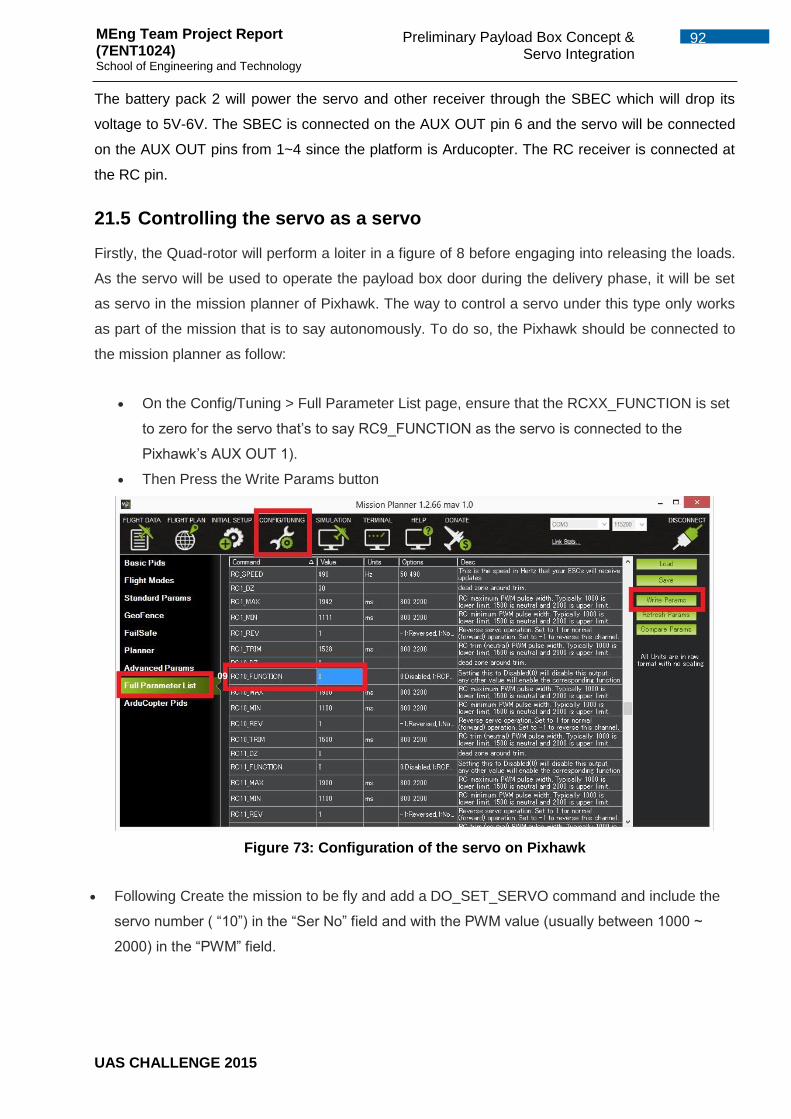
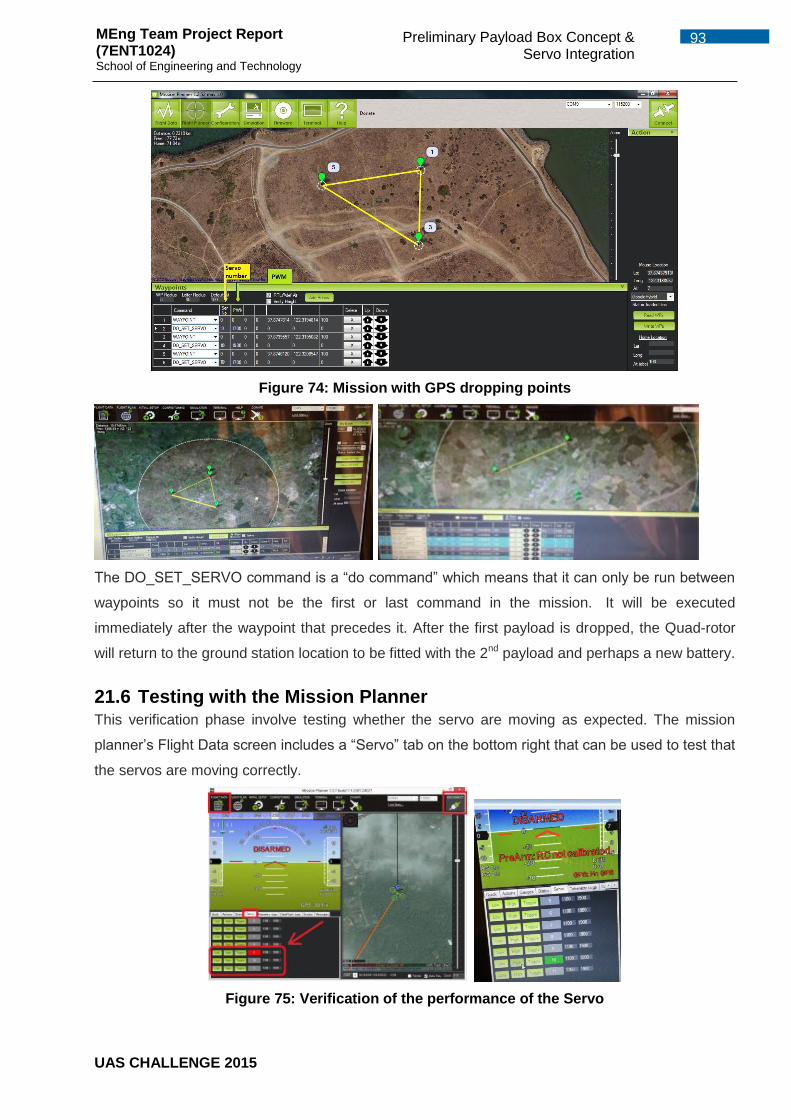
21.4 Schematics of connections from battery to servo through pixhawk ..............91 21.5 Controlling the servo as a servo ..................................................................92 21.6 Testing with the Mission Planner .................................................................93
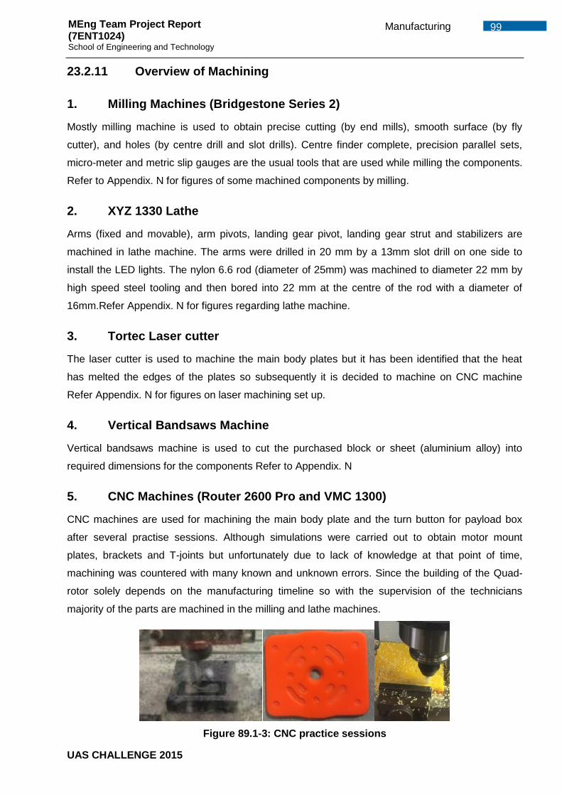
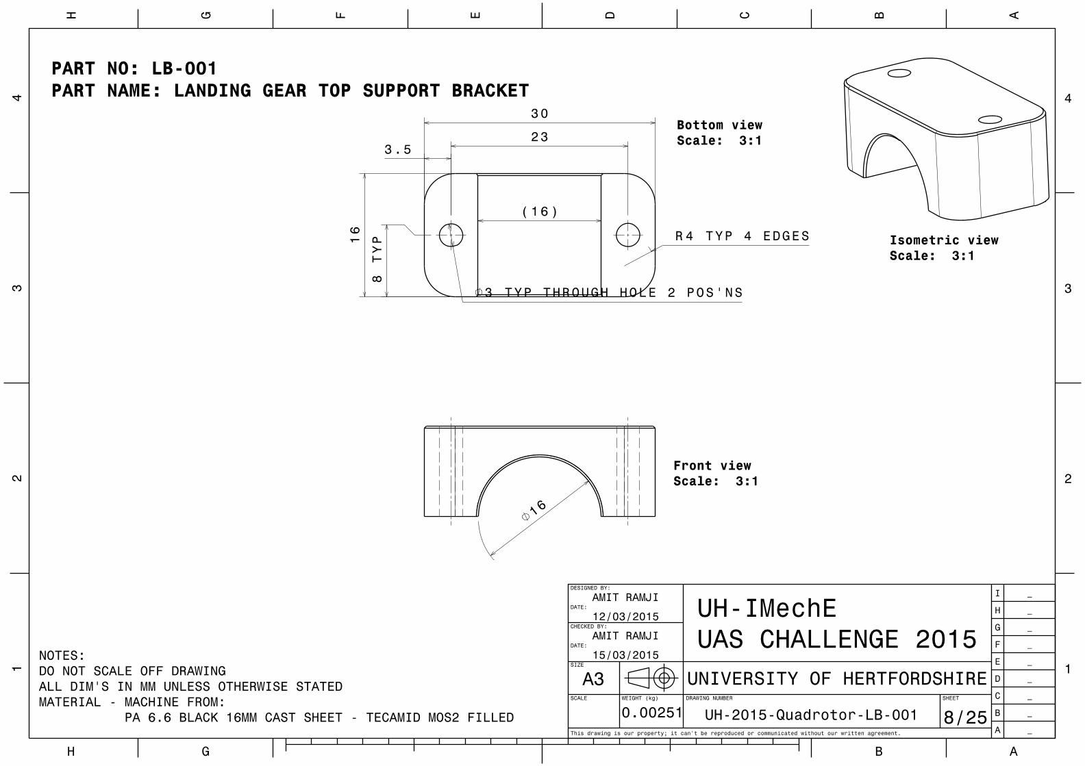
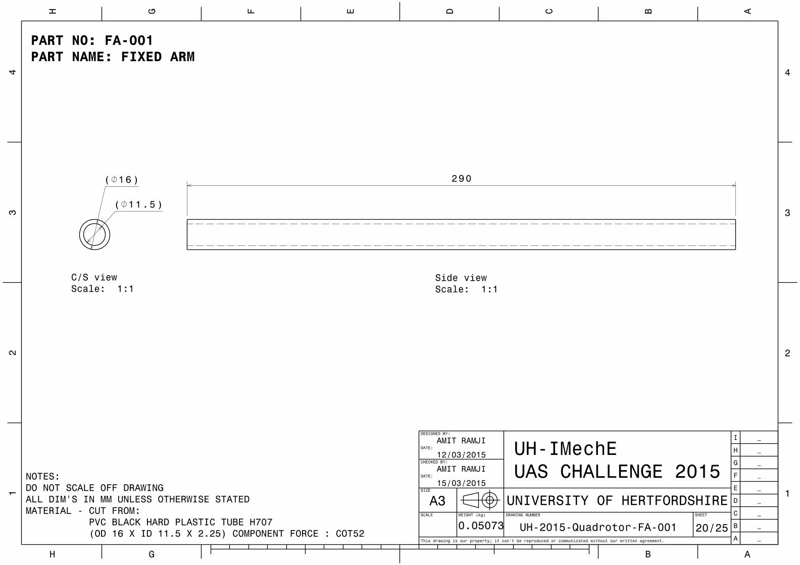
23.2 Manufacturing process of Quad-rotors components ....................................96 23.2.1 Fixed Bracket ........................................................................................96 23.2.2 Motor arm end bracket ..........................................................................96 23.2.3 Movable arm vertical fixed bracket /support bracket ..............................96 23.2.4 Landing gear top/bottom support bracket ..............................................97 23.2.5 Top/Bottom half T-joints ........................................................................97 23.2.6 Landing Gear Lug Bracket/ Pivot ..........................................................97 23.2.7 Arm pivot ..............................................................................................97 23.2.8 Main Body Plate ....................................................................................98 23.2.9 PVCs tubes ...........................................................................................98 23.2.10 Motor mount plate ..............................................................................98 23.2.11 Overview of Machining ......................................................................99
23.3 Challenges ................................................................................................ 100 23.4 Manufacturing Plan ................................................................................... 100 23.5 Machining Cost ......................................................................................... 100 23.6 Other involvements in the project .............................................................. 100
24 Test Rig ............................................................................................................. 101 24.1 Initial Conceptual Design of Gimbal Test Rig ............................................ 101 24.2 Octagonal Gimbal Test Rig ....................................................................... 102
24.2.1 Octagonal Model Mount Frame ........................................................... 103 24.2.2 Octagonal Mid Frame ......................................................................... 104 24.2.3 Octagonal Outer Frame ...................................................................... 105
24.3 Weight Estimation for Octagonal Test Rig ................................................. 105 24.4 Cost Breakdown for Octagonal Test Rig .................................................... 105 24.5 Manufacturing Stage of the Octagonal Test Rig ........................................ 106
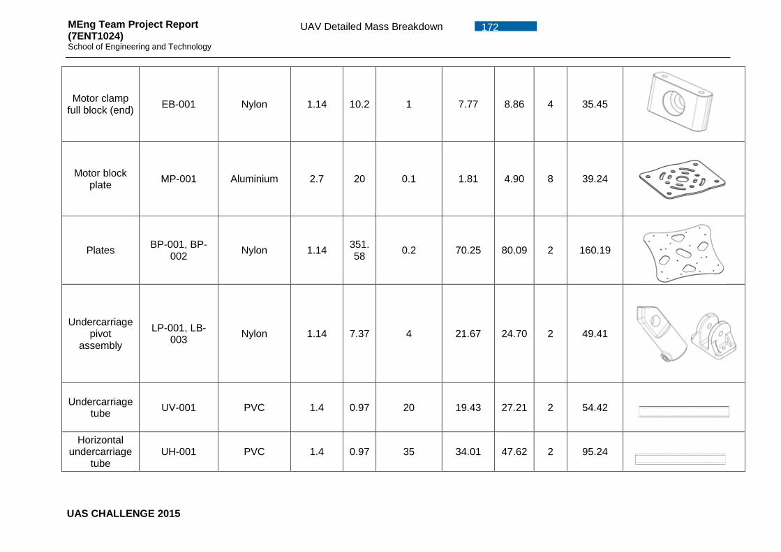
Conclusion ................................................................................................................ 119 REFERENCES .......................................................................................................... 121 Appendix. A ............................................................................................................... 125 Appendix. B UAV Design ..................................................................................... 141 Appendix. C UAV Detailed Mass Breakdown ....................................................... 171 Appendix. D UAV Detailed Cost Breakdown ........................................................ 177
UAS CHALLENGE 2015
vi TABLE OF CONTENTS MEng Team Project Report (7ENT1024) School of Engineering and Technology
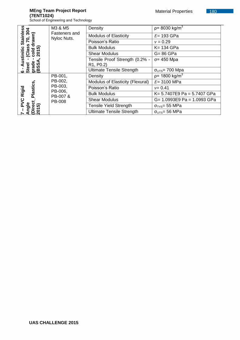
Appendix. E Material Properties .......................................................................... 179 Appendix. F Load Cases and Load Transfer ........................................................... 181 Appendix. G Stress Analysis ................................................................................ 182 Appendix. H Performance & Propulsion ............................................................... 219 Appendix. I UAS System Set Up ............................................................................ 261 Appendix. J Systems .............................................................................................. 269 Appendix. K Altitude control ................................................................................. 281 Appendix. L Verification and validation ................................................................... 289 Appendix. M Telemetry kit Specification ............................................................... 302 M.1. Servo calculation .......................................................................................... 307 Appendix. N Manufacturing .................................................................................. 308
N.1. Machining by milling machine .................................................................... 309 N.2. Machining by XYZ 1330 Lathe .................................................................. 309 N.3. Laser Cutting by Tortec Laser cutter ......................................................... 310 N.4. Cutting blocks by vertical bandsaws machine............................................ 310
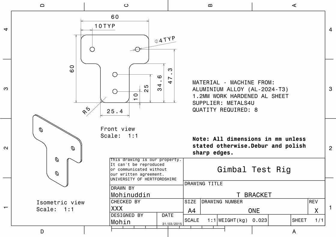
Appendix. O Test Rig ........................................................................................... 311 O.1. Initial Gimbal Test Rig Conceptual Design ................................................ 312 O.2. Updated Octagonal Gimbal Test Rig Assembly ......................................... 314 O.3. Octagonal Model Mount Frame Technical Drawing ................................... 316 O.4. Octagonal Mid Frame Technical Drawing .................................................. 318 O.5. Octagonal Outer Frame Technical Drawing ............................................... 320 O.6. Octagonal Gimbal Test Rig Stand Technical Drawing ............................... 322 O.7. Gimbal Test Rig Weight Estimation ........................................................... 324 O.8. Gimbal Test Rig Manufacturing Cost ......................................................... 326 O.9. Qualification test plan ................................................................................ 326 Electrical Performance Tests (Initial, In-Process, Final) ......................................... 326 Storage Temperature Cycling ................................................................................ 326 Thermal Shock ...................................................................................................... 326 Random/Sine Vibration .......................................................................................... 327 Operational Temperature Cycling .......................................................................... 327 O.10. Initial Involvement in the MEng Team Project ............................................ 327 O.11. Tri Angular Bracket Technical Drawing...................................................... 328 O.12. T-Bracket Technical Drawing .................................................................... 330
Appendix. O Design features for business case ................................................... 332
UAS CHALLENGE 2015
vii LIST OF FIGURES MEng Team Project Report (7ENT1024) School of Engineering and Technology
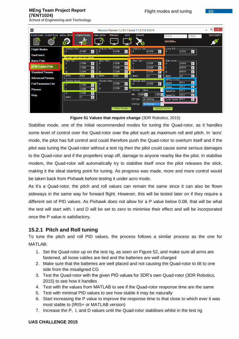
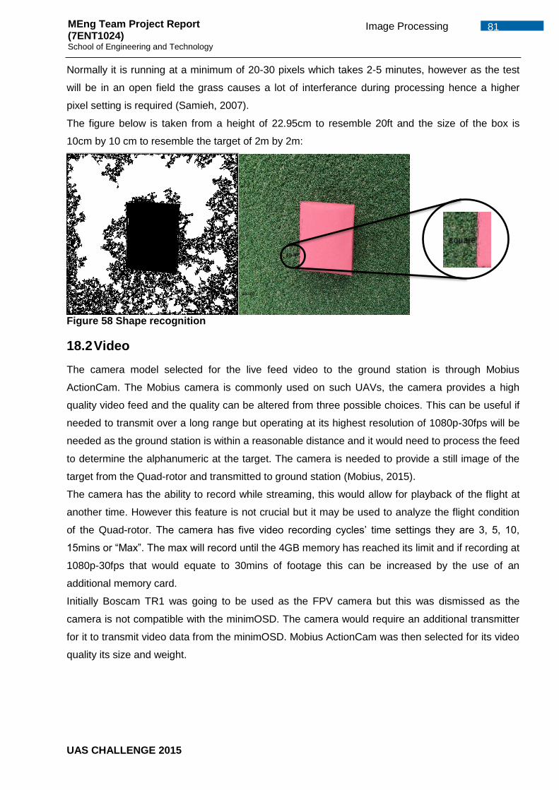
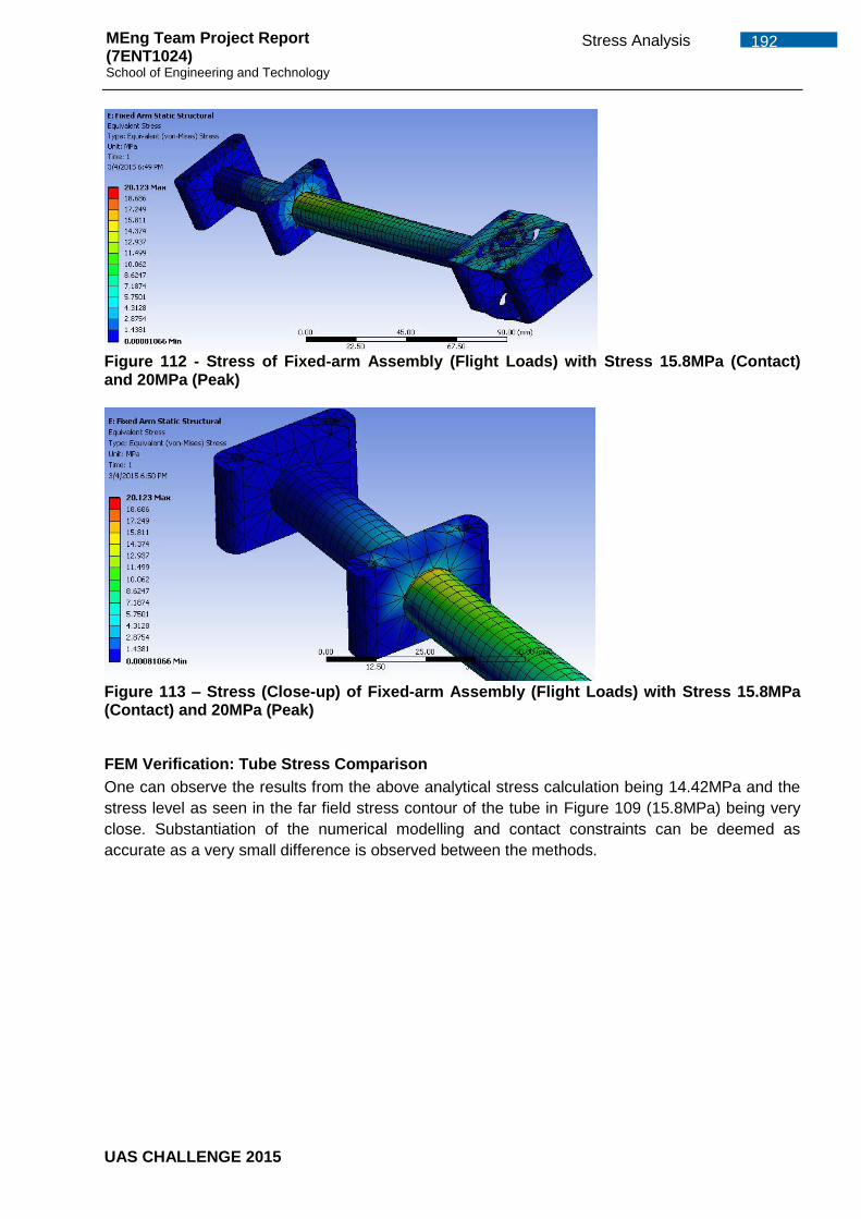
LIST OF FIGURES Figure 1 - Initial Concepts for Stage 1 convergence ..................................................... 2 Figure 2 - Concepts considered in the stage-2 convergence ........................................ 3 Figure 3 - Project Organization Chart ........................................................................... 5 Figure 4 - Progress (to date) of the project ................................................................... 7 Figure 5 - Leadership area of priority – Semester A (Left), Semester B (Right) ............ 8 Figure 6 – Performance Charts for Jonathan (a) and Zuber (b) ...................................12 Figure 7 - Quad-rotor design .......................................................................................14 Figure 8 - Stowage Instructions ...................................................................................15 Figure 9 - Quad-rotor in Stowed Configuration ............................................................15 Figure 10 – Removable Lightweight Payload Box .......................................................16 Figure 11 - Removable Lightweight Payload Box ........................................................16 Figure 12 - Payload Box with simple construction and failsafe mechanism .................16 Figure 13 – Payload Box with Payload Clearance .......................................................16 Figure 14 – Free Body Diagram - Flight and Landing Cases .......................................18 Figure 15 - Free Body Diagram - Landing Cases ........................................................18 Figure 16 - Free Body Diagram - Flight and Gust Load Cases ....................................19 Figure 17 – Fixed Arm Cross Section – See also Appendix G.7 ..................................22 Figure 18 – Mesh for Fixed-arm Assembly – Values as per Appendix G.6 ..................23 Figure 19 - Deflection of Fixed-arm Assembly (Flight Loads) with 7.6mm Deflection ...23 Figure 20 - Stress of Fixed-arm Assembly (Flight Loads) with Stress 15.8MPa (Contact) and 20MPa (Peak) .......................................................................................23 Figure 21 – Stress (Close-up) of Fixed-arm Assembly (Flight Loads) with Stress 15.8MPa (Contact) and 20MPa (Peak) ........................................................................24 Figure 22 - Simplified Plate Representations ...............................................................25 Figure 23 - Simple Plate Deflection Carried out on CATIA showing 4.54mm deflection ....................................................................................................................................26 Figure 24 - Flight and Gust condition of Main Body with 0.13mm Deflection................27 Figure 25 - Lateral Impact Case on Single Leg - 60.6MPa Stress ...............................28 Figure 26 – Stress Element A with Principal Stress for - Analytical – Undercarriage Combined Loading – Bending, Buckling and Torsion (G.13) .......................................29 Figure 27 - Arm and Mass for Rayleigh Method ..........................................................31 Figure 28 – Mass Representation of Motors, Blocks, Plates, Fasteners and ESC .......33 Figure 29 – Simplified FE analysis with 1st Nat freq as 19.64Hz – 69.3mm Deflection (Left) and 164MPa Stress (Right) ................................................................................33 Figure 30 – Simplified FE with 2nd Nat freq as 20.06 Hz (Left) and 3rd Nat freq as 134.6 Hz (Right) ....................................................................................................................33 Figure 31 – Simplified FE with 4th Nat freq as 224.1 Hz (Left) and 5th Nat freq as 411.9 Hz (Right) ....................................................................................................................33 Figure 32 – As Built FE Analysis - Mass Representation of Motors, Fasteners, Cables and ESC ......................................................................................................................34 Figure 33 – As Built FE analysis with 1st Nat freq as 451 Hz – 69.0mm Deflection (Left) and Stress (Right) .......................................................................................................34 Figure 34 - As Built FE analysis with 2nd Nat freq as 736 Hz (Left) and 3rd Nat freq as 1707 Hz (Right) ...........................................................................................................34 Figure 35 - As Built FE analysis with 4th Nat freq as 2 KHz (Left) and 5th Nat freq as 4.1 KHz (Right) .................................................................................................................34 Figure 36 - Prototype Quad Rotor ...............................................................................44 Figure 37: Waypoint Command File ............................................................................47 Figure 38: Telemetry Information transmitted to ground control station .......................50 Figure 39: Transmission Link Statistics (Serial Connection) ........................................51 Figure 40: Transmission Link Statistics (Telemetry Kit) ...............................................51 Figure 41 – PID System (Oscar, 2013) ........................................................................55
UAS CHALLENGE 2015
viii LIST OF FIGURES MEng Team Project Report (7ENT1024) School of Engineering and Technology
Figure 42 Loiter PID values .........................................................................................56 Figure 43 AltHold mode PID values .............................................................................57 Figure 44 Dataflash log in Stabalized mode opened in Mission planner ......................58 Figure 45 Battery fail safe settings chosen in Mission Planner ....................................60 Figure 46 Battery monitor settings chosen in Mission Planner .....................................61 Figure 47 Side view of the Quad-rotor .........................................................................65 Figure 48 Simulink model used ...................................................................................66 Figure 49 Quad-rotor oscillating with only the P gain (left), with P and D gain (right) ...67 Figure 50 PID values on Simulink ................................................................................68 Figure 51 Values that require change (3DR Robotics, 2015) .......................................69 Figure 52 Quad-rotor on the test rig ............................................................................70 Figure 53 Results of what Pixhawk should output (Copter.Ardupilot, 2015) .................70 Figure 54 Geofence configuration on Mission Planner ................................................74 Figure 55 Overall System Hardware Block Diagram ....................................................75 Figure 56 Overall Software Block Diagram ..................................................................77 Figure 57 Matlab alphanumeric code processing letter at 22.98cm .............................80 Figure 58 Shape recognition .......................................................................................81 Figure 59 Circuit Diagram of Ardunio ..........................................................................84 Figure 60: Hinge clamp ...............................................................................................85 Figure 61: electro-magnet ...........................................................................................85 Figure 62: Hinge-pin ....................................................................................................86 Figure 63: Other concept .............................................................................................86 Figure 64: CAD ...........................................................................................................87 Figure 65: Overall payload box ....................................................................................87 Figure 66: Horn and door connection ..........................................................................88 Figure 67: Start up release ..........................................................................................88 Figure 68: Fully Unlocked door ....................................................................................88 Figure 69: Complete release .......................................................................................89 Figure 70 - MG90S servo ............................................................................................89 Figure 71 - SBEC26 Turnigy .......................................................................................90 Figure 72: Schematics of connections .........................................................................91 Figure 73: Configuration of the servo on Pixhawk .......................................................92 Figure 74: Mission with GPS dropping points ..............................................................93 Figure 75: Verification of the performance of the Servo ...............................................93 Figure 76: Machined fixed bracket ...............................................................................96 Figure 77: Machined end bracket ................................................................................96 Figure 78: Machined Fixed bracket .............................................................................96 Figure 79: Machined bottom support bracket...............................................................97 Figure 80:T-joint on foam ............................................................................................97 Figure 81: Lug bracket ................................................................................................97 Figure 82: Landing gear pivot ......................................................................................97 Figure 83: Arm pivot for movable arm..........................................................................97 Figure 84: Cutting nylon plate in Laser machine ..........................................................98 Figure 85: Melted edges ..............................................................................................98 Figure 86: Plate after cutting .......................................................................................98 Figure 87: Assembled motor mount .............................................................................98 Figure 88: Motor mount plate ......................................................................................98 Figure 89.1-3: CNC practice sessions .........................................................................99 Figure 90.1-3: Failed attempts ................................................................................... 100 Figure 91 - Gyroscope Test Rigs ............................................................................... 102 Figure 92 - CAD Drawing of the Quad-rotor .............................................................. 104 Figure 93 - Test Rig Components .............................................................................. 106 Figure 94 - Test Rig Assembly .................................................................................. 106 Figure 95 - Nylon Material and Main Body Plate ........................................................ 107 Figure 96 - Compression Test conducted on Hounsfield Tensometer ....................... 107
UAS CHALLENGE 2015
ix LIST OF FIGURES MEng Team Project Report (7ENT1024) School of Engineering and Technology
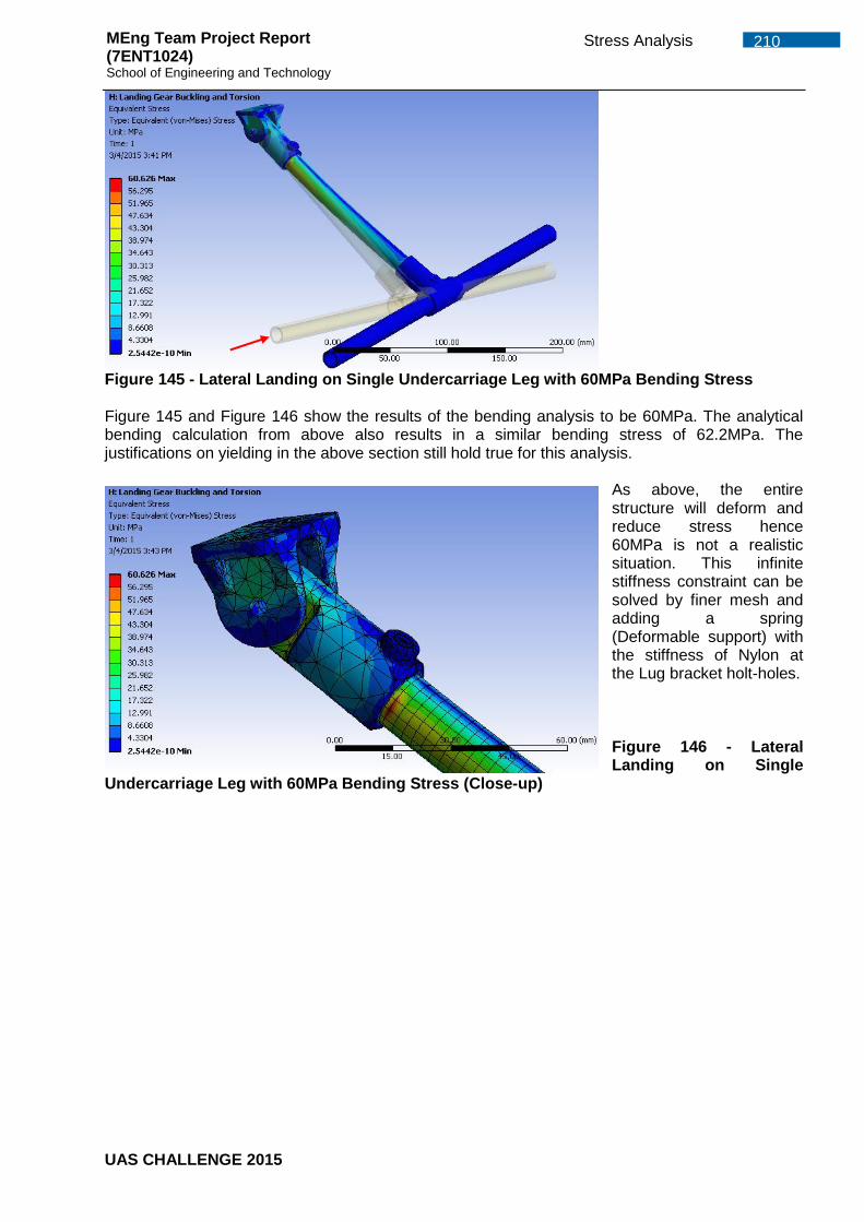
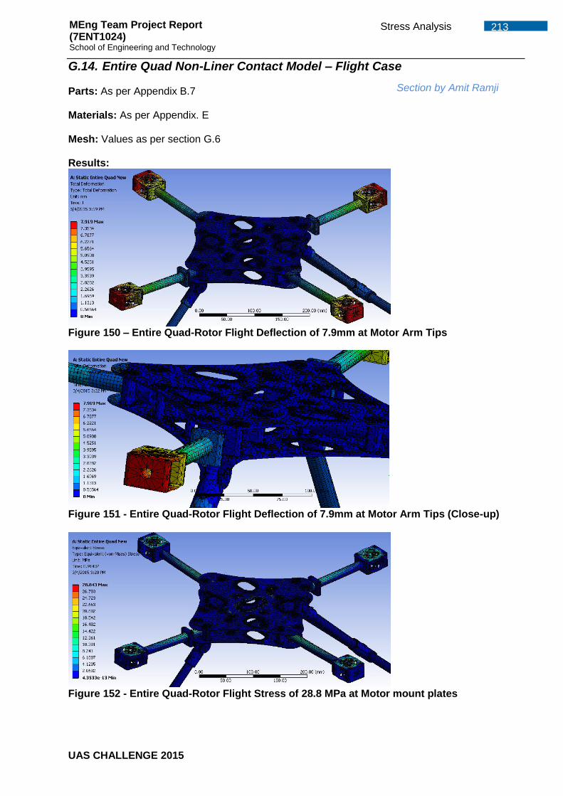
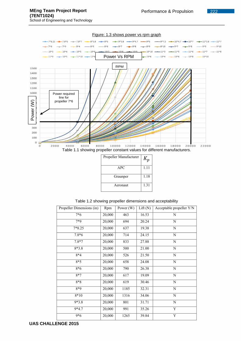
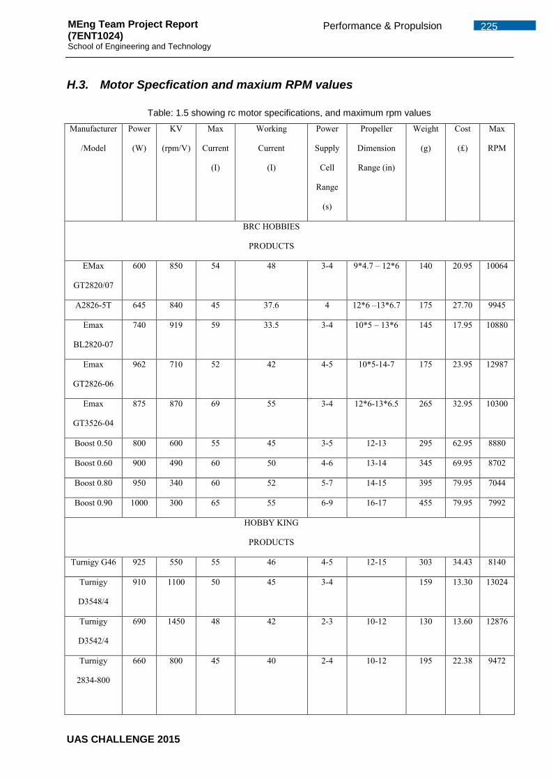
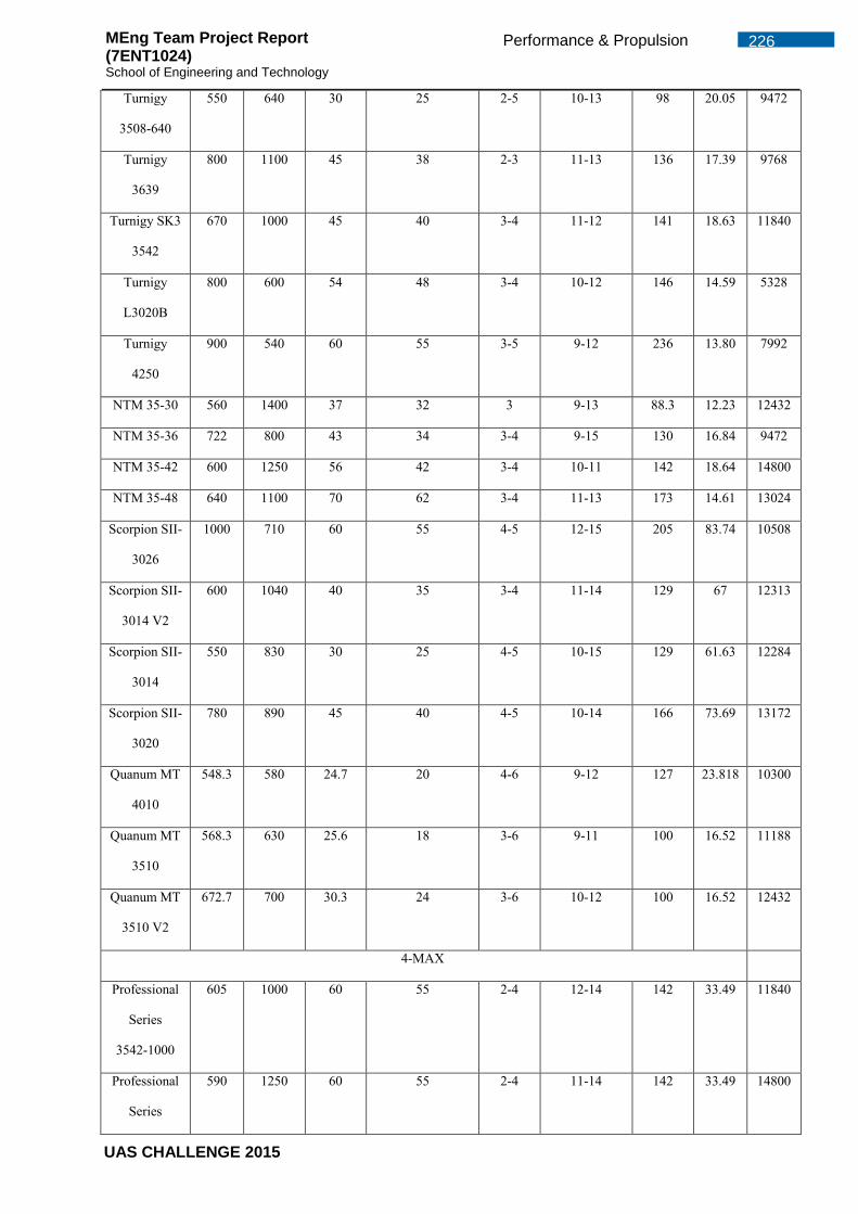
Figure 97 - Initial ball socket test rig .......................................................................... 108 Figure 98 - Autoquads Inspection Ltd Logo ............................................................... 109 Figure 99 - Permissions required for different UAS sizes ........................................... 113 Figure 100 - Break Even Graph ................................................................................. 118 Figure 101 - Overall View of Quad-Rotor ................................................................... 142 Figure 102 - Motor Mount Design (Left) & Undercarriage T-Joint (Right) ................... 142 Figure 103 - Undercarriage Pivot Design (Left) & Main Body Sandwich Design (Right) .................................................................................................................................. 142 Figure 104 - Movable Arm Pivot Design .................................................................... 143 Figure 105 - Project Main Body Area ........................................................................ 181 Figure 106 – SOLID187 Element (Ansys, November 2013c) ..................................... 185 Figure 107 – PLANE182 Element (Ansys, November 2013c) .................................... 185 Figure 108 - Arm Cross-section for Stress Calculation .............................................. 190 Figure 109 - Tension & Compression Stress in Arm .................................................. 190 Figure 110 – Mesh for Fixed-arm Assembly – Values as per Appendix G.6 .............. 191 Figure 111 - Deflection of Fixed-arm Assembly (Flight Loads) with 7.6mm Deflection .................................................................................................................................. 191 Figure 112 - Stress of Fixed-arm Assembly (Flight Loads) with Stress 15.8MPa (Contact) and 20MPa (Peak) ..................................................................................... 192 Figure 113 – Stress (Close-up) of Fixed-arm Assembly (Flight Loads) with Stress 15.8MPa (Contact) and 20MPa (Peak) ...................................................................... 192 Figure 114 – Mesh for Arm Assembly (With additional Tab) – Mesh Values as per G.6 .................................................................................................................................. 193 Figure 115 - Modified FB-002 for reduction in point contact stress concentration ...... 194 Figure 116 - Stress Concentration at Arm (without addition) Contact (a) & Close-up (b) .................................................................................................................................. 194 Figure 117 - Deflection of Modified Movable Motor Arm of 7.88mm for flight loads with SF ............................................................................................................................. 195 Figure 118 - Stress of Modified Movable Motor Arm of 20.8MPa for flight loads with SF .................................................................................................................................. 195 Figure 119 - Modified Movable Motor Arm with Stress of 20.8MPa for flight loads with SF (a) & Close-up (b) ................................................................................................ 195 Figure 120 - Load on the Lug (Niu, 1988) .................................................................. 196 Figure 121 - Components of the Load (Niu, 1988) ..................................................... 196 Figure 122 - Areas on the Lug ................................................................................... 196 Figure 123 - Lug Bracket Without Flange (Left) & with additional Flange (Right) ....... 197 Figure 124 – Lateral Unit Load Deflection (Left) & Stress (Right) of Lug Bracket Without Flange ....................................................................................................................... 198 Figure 125 – Lateral Unit Load Deflection (Left) & Stress (Right) of Lug Bracket With Flange ....................................................................................................................... 198 Figure 126 - Mesh for MP-001 (Appendix B.7) with values as per Appendix G.6 ....... 199 Figure 127 – Motor Plate Deflection (0.038 mm) and Stress (41.7 MPa) for flight case with SF at start-up ..................................................................................................... 199 Figure 128 - Error Elements in Model - Due to Separation at FB-001 and EB-001 .... 199 Figure 129 - Simplified Plate Representations ........................................................... 200 Figure 130 - Simple Plate Deflection Carried out on CATIA structural analysis ......... 201 Figure 131 - Mesh of Main Body Plate - Values as per Appendix G.6 ....................... 202 Figure 132 – Single Main Body Plate Analysis – with 17.8MPa Stress at contact holes for flight case with pressure load ............................................................................... 202 Figure 133 – Mass Representation of components and payloads as per Appendix. C .................................................................................................................................. 203 Figure 134 - Mesh of Main body assembly with Values as per Appendix G.6 ............ 203 Figure 135 – Contact model Flight Case for Main body assembly Deflection (left) and Equivalent Stress (right) ............................................................................................ 203
UAS CHALLENGE 2015
x LIST OF FIGURES MEng Team Project Report (7ENT1024) School of Engineering and Technology
Figure 136 - Contact model Flight Case for Main body assembly - Equivalent Stress with predicted locations ............................................................................................. 204 Figure 137 - Resolving Component to Determine Vertical Load ................................ 205 Figure 138 - Undercarriage Leg Under Pure Bending ................................................ 205 Figure 139 - Undercarriage Leg Under Pure Torsion ................................................. 206 Figure 140 - Stress Element A (Warren C. Young) .................................................... 207 Figure 141 - Plan View of Stress Element A .............................................................. 207 Figure 142 - Stress Element A with Principle Stresses .............................................. 208 Figure 143 - Undercarriage Mesh for Contact Model with values as per G.6 ............. 209 Figure 144 – Lateral Landing on Single Undercarriage Leg with 53.6mm Deflection . 209 Figure 145 - Lateral Landing on Single Undercarriage Leg with 60MPa Bending Stress .................................................................................................................................. 210 Figure 146 - Lateral Landing on Single Undercarriage Leg with 60MPa Bending Stress (Close-up) ................................................................................................................. 210 Figure 147 - Tip Landing on Single Undercarriage Leg with 60MPa Bending Stress . 211 Figure 148 -Tip Landing on Single Undercarriage Leg with 66mm Combined bending and torsion deflection ................................................................................................ 211 Figure 149 - Tip Landing on Single Undercarriage Leg with 71MPa Combined bending and torsion stress ...................................................................................................... 212 Figure 150 – Entire Quad-Rotor Flight Deflection of 7.9mm at Motor Arm Tips ......... 213 Figure 151 - Entire Quad-Rotor Flight Deflection of 7.9mm at Motor Arm Tips (Close-up) ............................................................................................................................. 213 Figure 152 - Entire Quad-Rotor Flight Stress of 28.8 MPa at Motor mount plates ..... 213 Figure 153 - Entire Quad-Rotor Flight Stress with Plate Stress peak at 14.42Mpa .... 214 Figure 154 – Downward Load - 1kg Payload and 10N Additional Load onto PB-005 Plate .......................................................................................................................... 215 Figure 155 - Side Load - 1kg Payload and 10N Additional Load onto Hinge Plate at 45deg to horizontal .................................................................................................... 215 Figure 156 - Side Load - 1kg Payload and 10N Additional Load onto short edge 45deg to horizontal............................................................................................................... 216 Figure 157 - Side Load as per Figure 156 - Showing Pre-mature Release due to global deflection ................................................................................................................... 216 Figure 158 – Downward Load as per Figure 154 - new design showing 0.73mm Deflection .................................................................................................................. 217 Figure 159 - Side Load as per Figure 155 –new rigid design and Deflection of 1.56mm .................................................................................................................................. 217 Figure 160 – Side Load as per Figure 156 and Figure 157 – with new design and deflection of 0.41mm* ................................................................................................ 217 Figure 161: Proof of Connection ................................................................................ 261 Figure 162: Mission Planner top menu ...................................................................... 262 Figure 163: Initial Setup for all components ............................................................... 262 Figure 164: Mission Planner Waypoint Entry Point .................................................... 262 Figure 165: Secondary Commands ........................................................................... 263 Figure 166: Area for writing flight plans into Pixhawk's Memory ................................ 263 Figure 167: Stability Tuning for Quad-rotor Control ................................................... 264 Figure 168: Mission Plannner environment for changing parameters ........................ 264 Figure 169: Fail Safe parameters .............................................................................. 265 Figure 170: Typical Set Fail Safe Values ................................................................... 266 Figure 171: Monitoring System Values ...................................................................... 267 Figure 172: Flight ready monitoring system ............................................................... 267 Figure 173: Quad-rotor Acceleration and Velocity parameters .................................. 268 Figure 174 Minim OSD V2.1 (unmannedtechshop, 2015).......................................... 276 Figure 175: 3DR uBlox GPS with Compass Kit (unmannedtechshop, 2015) ............. 278 Figure 176 CG calculations for the x and y-axis ........................................................ 281 Figure 177 CG calculations for z-axis ........................................................................ 281
UAS CHALLENGE 2015
xi LIST OF FIGURES MEng Team Project Report (7ENT1024) School of Engineering and Technology
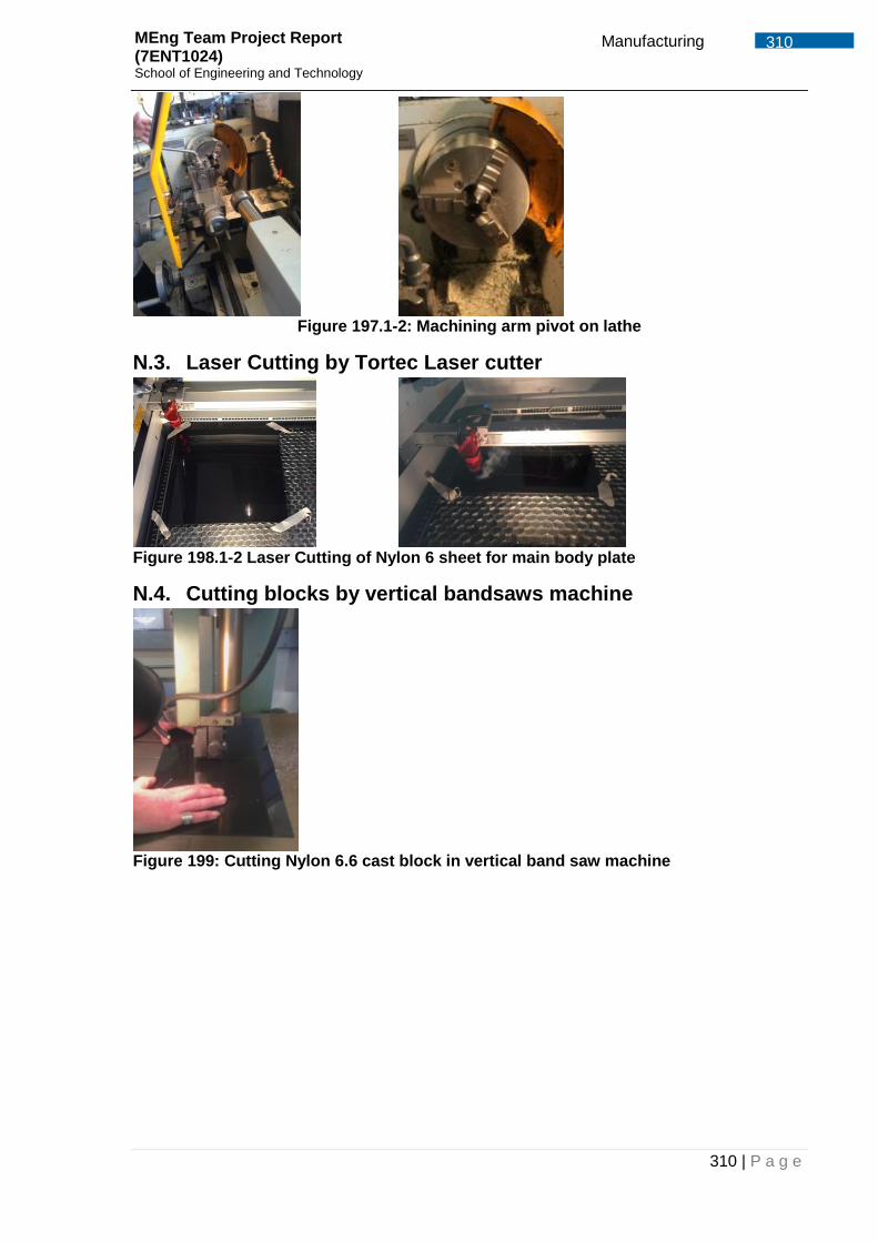
Figure 178 Overview of the Simulink model .............................................................. 286 Figure 179 Section to change PID values .................................................................. 287 Figure 180 Quad-rotor control mixing ........................................................................ 287 Figure 181 Quad-rotor dynamics ............................................................................... 288 Figure 182 GUI of the Quad-rotor general parameters .............................................. 288 Figure 183: Other CAD views .................................................................................... 306 Figure 184: schematics for the force calculations ...................................................... 307 Figure 185: Machined fixed bracket is CNC Router Pro 2600 .................................... 308 Figure 186: Dry assemble of landing gear lug, pivot and the vertical landing strut ..... 308 Figure 187: Slot bracket Figure 188: Turn button for servo motor ....................... 308 Figure 189: Support corners machined in CNC Figure 190: Triangle payload support glued with hinges 308 Figure 191: Drilling centre hole in fixed bracket Figure 192: Milling arm Pivot ........ 309 Figure 193: Chamfering of movable arm support Figure 194: Smoothing surface by fly cutter 309 Figure 195.1-2: Drilling using slot drills ...................................................................... 309 Figure 196: High speed steel tool .............................................................................. 309 Figure 197.1-2: Machining arm pivot on lathe ............................................................ 310 Figure 198.1-2 Laser Cutting of Nylon 6 sheet for main body plate ........................... 310 Figure 199: Cutting Nylon 6.6 cast block in vertical band saw machine ..................... 310 Figure 200 -OXV in storage configuration .................................................................. 332 Figure 201 - Electro-optic camera on the OXV .......................................................... 332 Figure 202- Main body of the OXV ............................................................................ 332
UAS CHALLENGE 2015
xii GLOSSARY MEng Team Project Report (7ENT1024) School of Engineering and Technology
GLOSSARY
3D Three Dimensional
AFS Advanced Failsafe
Atl Altitude
BEC Battery Eliminator Circuit
BOM Bill of Material
CAA Civil Aviation Authority
CAD Computer Aided Design
CCW Counter-Clockwise
CG Cenre of Gravity
CNC Computerised Numerical Control
COTS Commercial of the Shelf
CPR Cardiopulmonary Resuscitation
CW Clockwise
D Derivative
EMI Electro-Magnetic Inteference
ESC Electronic Speed Controller
EU European Union
FBD Free Body Diagrams
FE Finite Element
FEA Finite Element Analysis
FEM Finite Element Method
FPV First Person View
ft Feet
GPS Global Positioning System
Hz Hertz
I Integral
IAS Indicated Airspeed
IMechE Institution of Mechanical Engineers
km kilometer
knots Nautical Miles
KV kilo-volts
Li-PO Lithium Polymer
m metres
MEng Masters of Engineering
mm Millimeter
MPa Mega Pascals
MTOM Maximum Take-Off Mass
N Newtons
OSD On Screen Display
P Proportional
PA Polyamide (Nylon)
PDR Preliminary Design Review
PVC Polyvinyl Chloride
PWM Pulse Width Modulator
UAS CHALLENGE 2015
xiii GLOSSARY MEng Team Project Report (7ENT1024) School of Engineering and Technology
Quad Quadcopter
RC Radio Controller
RC Receiving (Radio)
RPM Revolutions Per Minute
RTL Return to Launch
SCA Sudden Cardiac Arrest
SUA Small Unmanned Aircraft
TX Transmission (Radio)
UAS Unmanned Aircraft System
UAV Unmanned Aerial Vehicle
VAT Value Added Tax
VLOS Visual line of Sight
W Watts
WBS Work Breakdown Structure
WP Waypoint
UAS CHALLENGE 2015
1 Introduction MEng Team Project Report (7ENT1024) School of Engineering and Technology
1 Introduction
The Unmanned Aircraft system (UAS) challenge is being introduced by the Institution of
Mechanical Engineers (ImechE) for the first time. Teams entered by universities will only constitute
of members from the undergraduates cohort. The competition will provide students from different
universities to develop and demonstrate leadership, teamwork and technical competencies. It’s
being held during the academic year 2014 till 2015. During this period the universities participating
in the competition will follow a structure of designing, developing and demonstrating. It will also
include design reviews, presentations and flight demonstration that will contribute to point scoring.
1.1 Competition Overview
The competition this year is built around a scenario of a natural disaster occurring with a large
areas distressed by an earthquake or tsunami. The scenario could involve many thousands of
people being cut off from supplies and in need for humanitarian aid. The job at hand is to supply
these areas with humanitarian aid food and first aid supplies. Time is critical and the UAS launch
site is some distance away from the affected areas. The UAS operates autonomously via pre-
determined waypoints to areas affected with the capability of image recognition to identify the
supply drop zone. The UAS can be programmed to carry out circuit trips and return to base and
repeating the mission.
For the competition, the UAS can have a maximum take-off mass of 7kg with Commercial Off The
Shelf (COTS) products not exceeding £1000. The UAS will need to perform a series of tasks such
as take-off, climb to an altitude between 100-400ft, cruise, follow a predefined route, drop two
payloads (Bag(s) of flour) weighing 1kg each at any reachable location and land back completely
autonomously.
1.2 Project Aims
The aims intended at the initial stage of this project were to;
Develop and demonstrate leadership, teamwork, technical competence, as well as
commercial skills.
Develop a complex system that will require design, development and demonstration with
regards to a demanding mission requirement.
Apply the knowledge learnt from previous academic years during the course of the
undergraduate engineering degree.
Represent the university in the UAS challenge, successfully compete and win.
Section by Alfred Dzadey
UAS CHALLENGE 2015
2 Design Rationale MEng Team Project Report (7ENT1024) School of Engineering and Technology
1.3 The Project Objectives
The main objectives set, in order to be successful are;
To design and develop a UAS with a MTOM less than 7kg and achieve autonomy in all
phases of flight and tasks.
Expenditure on COTS must not exceed £1000
To be able to switch between manual and autonomous flight.
To develop a UAS that can accommodate and deliver a 1 kg bag of flour.
To create an image recognition system to identify the drop zone and read alphanumerical
characters.
To complete the task in the fastest time possible.
2 Design Rationale
This section begins to discuss the solutions to the mission requirement outlined in the previous
chapter. It assesses various design options and converges to an ultimate solution. Upon evaluation
of various design concepts, it was conclusive that the best approach to tackle the problem was by
going forwards with a Quad-rotor and ground control station.
2.1 Design Convergence
A 2-stage design convergence approach was used to conclude which concept best meets the
requirements. The design concepts selected were compared against set criteria as discussed in
2.1.1 and 2.1.2.
2.1.1 Stage 1 Convergence
Application of the design solutions were analysed using a weighting system under criteria such as
manoeuvrability, structural integrity, stability
during flight and payload accuracy to name a
few. A workable concept was congregated
after a two-stage design convergence; Stage-
1 convergence was to determine the type of
aircraft to be used where the concepts
assessed were:
Fixed Wing
Helicopter
Osprey
Multi-Rotor
Figure 1 - Initial Concepts for Stage 1 convergence(UAVClub, 2015)
Section by Alfred Dzadey
UAS CHALLENGE 2015
3 Design Rationale MEng Team Project Report (7ENT1024) School of Engineering and Technology
The results from the Stage-1 convergence demonstrated that a multi-rotor would be the best option
to meet the product design specification.
2.1.2 Stage 2 Convergence
Stage-2 design convergence was to determine which multi-rotor system would best meet the UAS
requirements. Criteria used in stage-2 included redundancy (motor failure), manufacturing
complexity, power consumption, noise, payload capacity, structural integrity and costs to name a
few. The concepts considered during the stage-2 design convergence were:
Quad-Copter
Hex-rotor
Octacopter
3 arm – 6 rotors
Figure 2 - Concepts considered in the stage-2 convergence (UAVClub, 2015)
Upon comparison between the multi rotors under the above criteria, the Hex-rotor was found to be
the best concept that would meet the set criteria. Appendix C details the rationale and justification
for this selection.
2.2 Further analysis
Upon initiation of the design, a mass breakdown of all components for this proposed system was
established, it was found that the Hex-rotor would be overweight. The only solution forward was to
lose two arms to reduce it’s weight hence reducing from a Hex-rotor to a Quad-rotor design. This
allows the design to be approximately 6kg with all possible components and a single payload
accounted. The quad rotor design is 1 kg under the constrained maximum weight of 7 kg, providing
contingency for any miscalculations or any unplanned additional weight.
UAS CHALLENGE 2015
4 Project Management MEng Team Project Report (7ENT1024) School of Engineering and Technology
3 Project Management
To achieve the project objectives, effective organisation, planning, budgeting and management
styles were adopted. This section describes the organisational structure and the key management
tasks undertaken to deliver the project successfully. It describes the leadership, organisation
structure and role selection, project planning, budgeting, people and conflict management, finally a
review on both team leads is discussed.
3.1 Role of the Project Manager
The project management role comes with responsibilities involving the following;
Progress –ensuring the deliverables are being completed within the set timescale.
Budgeting – control the money being spent to ensure the deliverables are being completed
within the baseline cost.
Performance – ensuring the team is performing enough to achieve the goals set out.
Reporting – scheduling regular meetings with team members and supervisors to report
progress and resolve issues.
Planning/Change – handling and resolving any unexpected changes to project without
hugely affecting the outcome of the project or delivery.
Risk – to implement any contingencies into the time plan and budget to manage any
unforeseen risks affecting the project delivery.
Leadership and motivation – Motivating and maintaining morale during the duration of the
project.
Purchasing – dealing with orders being placed, tracking and informing the group of the
delivery progress of the order.
Welfare – taking into account the commitment of individuals while setting actions without
jeopardising the progress of the group.
Conflict – resolving any disrupt between team members and allowing a good working
environment.
Presenting – handling the compilation of all group reports and presentations in terms of
collating, proof reading individual reports and structuring.
3.2 The Team Structure
Project organisation structure needs to be one that facilitates the coordination and implementation
of project activities. The project organisation needs to create an environment in which there are
interactions among team members with minimal conflict, disruption or overlapping. The team
comprises of twelve students; nine studying aerospace, two studying aerospace with space
technology and one studying aerospace systems. With the project being systems related, the team
lacked expertise in that area meaning more work needed to be carried out. Figure 3 shows an
organisational structure to highlight each person’s responsibility and tasks carried out.
Section by Alfred Dzadey
UAS CHALLENGE 2015
5 Project Management MEng Team Project Report (7ENT1024) School of Engineering and Technology
Figure 3 - Project Organization Chart
As with any large project it is advisable to split project team into sub teams to enable the project to
be manageable. This allows deliverables to be split into smaller tasks with clear objectives within
sub teams. It enables the team members in the sub teams to know exactly what actions are
required for an effective contribution. Another advantage of this set up is that there is a clear line of
authority and also team members will become familiar with each other since they work together in
the same area. Effective communication channels allow for the project manager and team leaders
to effortlessly interact and report back any difficulties or progress updates. Zuber and Jonathan
were appointed sub team leader due to both of them being extraverts and possession leadership
qualities as assessed using MBTI results. The structural team handles tasks relating to the design,
quality control, compliance, manufacture, assembly, test and certification of the UAS. The systems
team handles tasks relating to performance and propulsion, stability, control systems, flight and
navigation, imaging system, mission control, safety and payload deployment system.
3.3 Project Planning
The key to a successful project is in the planning, hence continual involvement and forward
planning must be carried out prior to project initiation. It involves the use of schedules such as
Gantt charts for planning and subsequently to report project progress. Initially, the project scope
was defined and the suitable method of successful delivery of this project was determined. The
following step was working out the durations and having contingency for all the various tasked
3.8 Obtain approval to proceed 9.4 Deliver FRR report
3.9 Preliminary Design complete 10 Competition
3.10 Deliver PDR to IMeche 10.1 Design Presentation
4 Final Design ready for purchase 10.2 Flight Readiness Review
4.1 System components finalised ready for purchase
10.3 Competition day
4.2 Propulsion components ready for purchase 10.5 UAS CHALLENGE FINISH
Table 1- Work Breakdown Outline Once the work breakdown structure was established, the project schedule was created and is used
as a baseline schedule for the whole duration of the project life. Using the project plan, a graph
representation of the current progress has been created and is shown in Figure 4. This is a
simplified overview of the progress made so far which is detailed in the project plan shown in
Appendix A.2. The progress made so far and completion of tasks can be seen in more detail in the
project plan.
UAS CHALLENGE 2015
7 Project Management MEng Team Project Report (7ENT1024) School of Engineering and Technology
Figure 4 - Progress (to date) of the project
3.3.1 Milestones
The major milestones set for this project are as follows:
30 October - Defining scope of project
16 November - Complete Design Analysis
05 December – Deliver PDR to IMechE
16 December – Design ready for purchase
1 April – Deliver CDR report
30 May - Integration testing complete
12 June – Deliver FRR report
1 July Design presentation
July – Competition Day and End of UAS Challenge
3.4 Leadership
Leadership involves creating an inspiring vision and managing the delivery of the vision.
Leadership brings together the skills needed to achieve this vision. Therefore, it is vital that the
style of leadership is rightly chosen for team performance and effective quality. The style of
leadership may vary during the duration of the project. ‘The three circle model’ is a concept that is
used to represent the dynamics of a group displaying the percentage of effort in terms of team,
task and individual. (Adair, 2012) It is critical for the leader to monitor these areas to ensure that
one area doesn’t needlessly become dominant. An example is where the group may take long to
make decisions due to the size of the group and differences of opinions. This is mitigated by
creating a cut of point whereby the group is no longer being effective in the decision making
process.
0 10 20 30 40 50 60 70 80 90 100
Scope
Design Specification/System Requirements
Preliminary Design
Final Design ready for purchase
Critical Design Review (CDR)
Order parts
Manufacturing & Assembly
Testing and Validation
Integration Testing
Flight Readiness Review (FRR)
Competition
Progress (%)
Project Progress to date
UAS CHALLENGE 2015
8 Project Management MEng Team Project Report (7ENT1024) School of Engineering and Technology
Consequently, the leader will conclude what has been discussed and make the final decision. In
Figure 5 the three circle diagrams depicts in which area leadership was stressed during the
academic year.
Figure 5 - Leadership area of priority – Semester A (Left), Semester B (Right) During the academic year the leadership style varied between a democratic and an authoritarian
style. Semester A involved initial stages of the project whereby there were a lot of group
discussions. It involved the development of the design concept hence a democratic style was
chosen to allow everyone’s input in decision making. This method allows members to feel free to
express their opinion. For people who were intrinsic it was encouraged for them to voice their
opinion in all decision making by actually asking what their thoughts were. This allowed team
members to grow in confidence and voice their opinion, which was good for the group dynamics. At
times, it made decision making problematic but it’s the responsibility of the leader to step in and
make the final decision based on the majority vote.
In semester B, the approach of leadership changed. It required a leader of a more authoritarian
style. This is due the fact that the project had shifted from a design phase to a development and
manufacturing stage. This stage is on a critical path hence an authoritarian style of leadership was
needed to help mitigate any delays. This involved a lot of communication on a daily basis to
establish what was set out to achieve and what was actually accomplished at the end of the day.
Furthermore, constant checking up on individuals was needed to ensure progress and also to deal
with unforeseen circumstances. For example, a time came when there was an issue with the
machining of the main plates for the airframe. The team required more material but there was none
left. As the leader, it was essential to step in and resolve the solution. This circumstance was
handled immediately by contacting the supplier and explaining the situation at hand and how
urgent the material was needed. As a result, the supplier ‘Ensinger’ was able to send out an order
as a free sample for next day delivery.
TEAM
TASK
INDIVIDUAL
TEAM
TASK
INDIVIDUAL
UAS CHALLENGE 2015
9 Project Management MEng Team Project Report (7ENT1024) School of Engineering and Technology
3.5 Team Communication
Throughout the project, weekly meetings with team members were undertaken to discuss any
updates, complications and actions required. Also during semester A, we had weekly meetings on
Tuesday noon with our supervisors to discuss the updates, complications and new actions set for
the week coming and where a register of attendance is taken. Ours meetings are made effective,
by using agendas and minutes. Minutes are used to record the discussions, conclusions and
actions set whereas the agenda was used to structure our meetings by having a schedule stating
exactly what topics are to be discussed and who is presenting the topic of discussion. An example
of the minutes, agenda can be seen in Appendix A.3 and A.4. Communication is essential for the
progression and success of a group. Without effective means of communication the group
production comes to a standstill. Communication methods used in the project are as follows. A
breakdown of the various group communications methods are presented in Table 2
Communication Aids
Types/Techniques Description Email Agendas are always sent out 24 hours before our official meetings
with our supervisors and also minutes are also sent out 24 hours after the meeting as a follow up of what was discussed and agreed in the meeting.
WhatsApp
It is used a form communication where all group members can discuss about findings or issues
Google drive An account was made for sharing files between members in the group. Each individual in the group has a folder with their name and hence can share their work to the group
Text messages and phone calls
For contacting individuals in the group privately for any needs regarding the project
Group meetings It’s used as a way to meet up face to face to discuss and updates or issues and to check progress of work and make decision.
Table 2 - Forms of communication used in project
3.6 Project Budgeting
For this project, there was a need for managing the funds to stay within the financial range of
£1390. A budget was used to project the costs and also to track the funds. A comparison of the
actual funds and the budget estimation has been made to see how much has been spent. Table 3
shows the operational budget. On the left are the projections for the budget as of November 2014.
On the right hand side we have the actual unit prices and quantities purchased. The final column
presents the difference between the two. The budget also includes a contingency factor of 1.2 to
anticipate any failures crashes or even unforeseen costs. A more detailed representation of the
product cost can be found in Appendix. D.
UAS CHALLENGE 2015
10 Project Management MEng Team Project Report (7ENT1024) School of Engineering and Technology
Budget Estimation as of
01/11/2014 Actual as of 23/04/2015
Part Unit Price Quantity Unit Price Quantity Difference
Flight controller £150.00 1 £159.98 1 -£9.98
Telemetry kit £40.00 1 £35.80 1 £4.20
GPS Module £50.00 1 £53.94 1 -£3.94
ESC £30.00 5 £27.16 5 -£2.84
Propellers £5.00 6 £3.95 6 £6.30
Brushless Motors £20.00 5 £19.16 5 £0.84
Camera £50.00 1 £56.41 1 -£6.41
OSD £30 1 £29.99 1 £0.01
Batteries £90.00 2 £60.40 3 -£1.20
RC Transmitter £30.00 1 £14.99 1 £15.01
Air frame including landing gear and payload box
£150.00 1 £146.30 1 £3.70
Extra cable and connectors £50.00 1 £20.95 1 £29.05
Test Rig* £150.00 1 £132.08 1 £17.92
Unplanned Quad Parts £0.00 0 £21.02 1 -£21.02
Delivery Costs* £100.00 1 £125.06 1 -£25.06
Total: £1,157.63
C. Factor (x1.2) 1389.16
Current Total: £1,100.94
Remaining: £231.53
*Not Part of COTS Percentage: 79.252438 Table 3 - UAS Challenge 2015 Budget
3.6.1 Summary of Project Budget
The main outcome of the budget that can be identified is that the project is £231.53 (21%) within
budget. This includes the majority of the UAS components, materials and also a test rig with
minimal additional items left to purchase. The flight controller is the team’s most expensive COTS
due to aspiring for a flight controller that was widely used. This will allow us access to open-source
information about autonomous control of the UAS. A complex alternative was to make use of an
Arduino board costing approximately £60 and to program the flight plan manually, hence potentially
saving £100. The team has had to spend some money for items that were not considered initially.
This has accumulated to a total of £210.03 which has been put that as unplanned Quad parts. We
have also gone over budget slightly on delivery cost which was unplanned. A detailed expenditure
of the project to date can be seen in Appendix. D
3.6.2 Source of Funding
There were two main sources funding this project. One was the funding from the university and the
other was from the team members. The university provided the team with £1000 to cover
everything from designing manufacturing, testing and the development of the product. Later, it was
found that this budget was insufficient and that it would only cover the purchase of materials and all
the components required for a Quad rotor design that would achieved good results for the
UAS CHALLENGE 2015
11 Project Management MEng Team Project Report (7ENT1024) School of Engineering and Technology
competition. The team decided to invest in the project extending the budget to £1500 with the aims
of winning an award and being reimbursed.
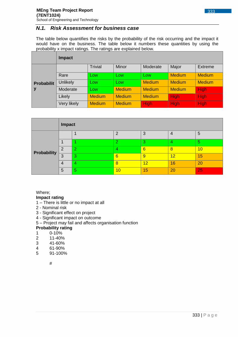
3.7 Risk Management
Due to a team member previously dealing with the safety case, the task of risk management was
delegated to that member. The rationale behind this decision was that the safety case and risk
management interlink so it was logical to delegate these tasks to an individual. The risk
management can be found in Appendix J.3.
3.8 Conflict management
Conflict is a common phenomenon in group projects. It’s inevitable and hence important as a
leader to understand the various conflict resolution techniques. Conflict isn’t always a bad thing
because it can present opportunities for improvement. Teams usually try to avoid or ignore
conflicts rather than addressing it. It can also have an effect on the team performance, as a leader
it is my duty to prepare for conflicts by creating an atmosphere that allows for dealing with conflicts
without relationship and emotional problems, for instance forming an atmosphere that supports
constructive criticism so that discrepancies can be expressed. Conflicts in the group were resolved
mostly using the following steps: Firstly, the people were separated from the problem by
diagnosing what was causing the issue and then various options were developed in order to
resolve the problem at hand. Secondly, the options were evaluated and the unimportant issues
were distinguished from the vital problems. Additionally, a common ground between each side was
found and a solution for both sides was mutually agreed upon. Finally, the agreement was
monitored to ensure that it was kept.
An example whereby this process was exercised was a situation involving to members in the team.
The issue sparked during a previous report submission where Micky had made a copied CAD
version of the payload box design. Amit had previously made a design for the payload housing due
to severe schedule delays in the project and was not happy about Micky’s contribution and
informed me that for the MEng report he doesn’t want Micky to present that design because he did
not design the payload box and was not involved during the decision making. To resolve this, a
conference call was made between the leader and the two team members. Both sides of the
argument was requested, Micky said that the only reason he had made a new CAD file was to
show how the servo mechanism was going to be applied to the box. It was clear that it was a lack
of communication between the group and absentee Micky had led to this confusion. It was
concluded that Amit would discuss the payload box design itself and its structural analysis whereas
Micky would discuss the servo mechanism and how it interacts with Pixhawk. The conversation
was concluded by further asking if both team members were happy with the decision made and
they were both were pleased with the outcome.
UAS CHALLENGE 2015
12 Project Management MEng Team Project Report (7ENT1024) School of Engineering and Technology
0
1
2
3
4
5
Jonathon Ebhota
0
1
2
3
4
5
Zuber Khan
3.9 Performance Review Performance management allows a business, or in this case, allows the project manager to
determine the strengths and weaknesses of each member in the team. It provides feedback back
to the person being performance managed in areas where they need to develop their skills and
knowledge which they can apply to improve the project in either project delivery or team dynamics.
A performance review of each team member was made to see their strengths and weaknesses
which are broken down into seven different categories; Enthusiasm, Team value, Planning,
Execution, Delivery, and Contribution. As the team itself is quite large, two members were
appointed as team leaders to overlook specific sections; structural and systems. For these two,
three further criteria’s were included; Coaching, Managerial skills and Motivational skill. The
breakdowns of each criterion are as follows:
Enthusiasm: passion and interest for the role and subject
Coaching: training and guiding other team members through their work performance and
subject knowledge
Managerial skills: ability to plan and delegate workload, communicate between team
members, and solving issues between members fairly and objectively
Motivational skills: being able to understand what motivates each member and keeping
them motivated
Team value: quality and information being passed on, insight in topics, availability for help
when asked and general team sportsmanship
Planning: time management, planning for delays and possibly additional workload
Execution: method of execution, holding up other members
Delivery: quality of final work produced for individual role
Contribution: overall workload taken, experience and insight provided and contribution to
the team
Figure 6 – Performance Charts for Jonathan (a) and Zuber (b)
UAS CHALLENGE 2015
13 Project Management MEng Team Project Report (7ENT1024) School of Engineering and Technology
Figure 6 presents the performance chart of the two sub team leaders. It describes on a scale from
0 to 5 how they are rated against each category, where 5 is classed as the best and 0 is classed
as the worst. On average it can be seen that Zuber was excellent in most of these categories
whereas Jonathan mostly was good all round and both lacked in motivating team members. A
more detailed individual performance review of each team members can be seen in Appendix A.5.
3.10 Evaluation
Self-evaluation allows one to reflect on how effective their performance was during the project.
During this process, the performance of the leader can be assessed to see how effective it was,
noting areas that need improvement. It should also list the skills developed and what skills need to
be worked on in order to be a better leader if they were to do the project the second time round.
Using the Project manager evaluation form in the Appendix A.6, it was possible for me to evaluate
my performance. It was found that the team scored me 5 in regards to management of the
team/project, having the ability to work with others, ability to present options and reach decisions
and the ability to locate and utilize resources effectively. As a leader of the team and project these
were my strongest areas. An area in which I was marked to be average was the ability to anticipate
and analyse problems. It seems like this is an area in which I need to focus on if I were to manage
a project again. Moreover, as part of the evaluation there were phrases regarding the likelihood to
work again with the project manager on another project. It was reported back that they would be
willing to work with me again on another project with some changes applied.
Further points were asked for regarding any specific strong points/ weak points about my
performance. The positives were: Firstly, I had good form of communication skills and
persuasiveness. Secondly, I was always going the extra mile and continuously standing up for the
team in front of supervisors and I was very supportive. Evidently, it is clear that I possess essential
skills such as good communication, persuasiveness and I’m very supportive of the team member
because I believe as the leader of the team it is my duty to be the voice of the team and the person
held accountable for the team. The negatives were: primarily, I need to keep within deadlines and
secondly, I am far too lenient. These are areas that need to be worked if I’m to manage another
project. I’m apparently too lenient when it comes to deadlines. During the period of the project, we
have had team members that have had personal issues outside the academic work. It meant that if
I had set deadlines for work to be completed and a team member said they couldn’t complete the
task due to personal problems, I would be reluctant to give them more time. This could potentially
cause delays in the initial time plan and hence maybe keeping to a strict deadline regardless of the
personal background situation might be necessary and something I could consider next time.
Overall, I would say I have done a good job in managing this group so far and I have learnt some
vital lessons regarding what to do and what not to do as a project manager.
UAS CHALLENGE 2015
14 Quad-Rotor Design MEng Team Project Report (7ENT1024) School of Engineering and Technology
Section by Amit Ramji 4 Quad-Rotor Design A Hex-Rotor had been considered during the early stage of the design convergence process,
however during the detail design stage this had been changed to a Quad-rotor design. The reason
for such a dramatic design change is due to mass and cost constraints and is detailed in Appendix.
C and Appendix. D respectively.
Upon detailed consideration of the mass and materials involved with the Hex-rotor, it had been
decided to significantly modify the design and produce a Quad-rotor. As detailed in Appendix. C,
the reduction in mass by alterations in geometry, reduction of parts and optimising the use of
materials results in a very lightweight structure as shown in Figure 7 below. The use of extruded
Nylon 6 main body plates (Appendix B.7) allows for a lightweight structure that is fastened together
into a sandwich design to provide a significantly rigid structure. The use of Carbon Fibre has been
entirely eliminated due to financial constraints; hence a suitable strengthened alternative is
selected. The use of M3 bolts and Nylon 66 blocks (Appendix B.7) allows for a rigid main structure
with multiple load paths. Using the machined Nylon 66 blocks in compression allows for the
majority of the loads to remain in-plane of the main body plates and allows the fasteners to take up
most of the load.
Details of the design architecture and in-depth features are found in Figure 7 through Figure 9 and
Appendix B.7.
Figure 7 - Quad-rotor design
UAS CHALLENGE 2015
15 Quad-Rotor Design MEng Team Project Report (7ENT1024) School of Engineering and Technology
4.1 Design Rationale - Quad-Rotor
Figure 8 - Stowage Instructions
Figure 9 - Quad-rotor in Stowed Configuration
Fixed Nylon bracket in compression
Moving Nylon tube position support bracket
Rotating Nylon
Mount with
Spacers and
Through Bolt
Sandwich Design to minimise bending effect with rigid links (M3 bolts)
In-Plane Shear for plates
Remove Quick Release pins (2-Off) for compact stowage.
UAS CHALLENGE 2015
16 Quad-Rotor Design MEng Team Project Report (7ENT1024) School of Engineering and Technology
Section by Amit Ramji 4.2 Payload Box Design and Mechanism Figure 10 through Figure 13 show the design of the payload housing with a simple trap-door type
design activated by gravity with release of a servo. The design can be adapted to use either rotary
servo motors or linear actuators. The structural analysis of the payload compartment and its
development is carried out in Appendix G.15 and G.16. Dimensions of the payload compartment,
component parts and BOM can be found in Appendix B.7.
Figure 10 – Removable Lightweight Payload Box
Figure 11 - Removable Lightweight Payload Box
Figure 12 - Payload Box with simple construction and failsafe mechanism
Figure 13 – Payload Box with Payload Clearance
UAS CHALLENGE 2015
17 UAV Mass Breakdown MEng Team Project Report (7ENT1024) School of Engineering and Technology
5 UAV Mass Breakdown Initially a Hex-rotor was considered with a structure mass of 1777.5g, an all-up mass of 7371.9g
with a single payload. The mass of the UAV must not exceed 7kg, hence a complete redesign as a
Quad-rotor has been fulfilled.
A detailed Quad-rotor mass calculation (Appendix. C) has been carried out to ensure the UAV is
within CAA certifiable weights limits to enable flight and to ensure the requirements are met
(IMechE, Jan 2015). The total mass of the Quad-rotor is 6026.2g with single payload. An itemised
breakdown shown in Appendix. C.
UAV Structural Mass
The total mass of the structure is calculated to be 1012.5g including all the materials and fixings
depicted in Appendix B.7. The structure mass is well below the target mass of 1.5 Kg, due to the
extensive and detailed stress analysis carried during the detailed design stage. The entire itemised
breakdown can be observed in Appendix. C.
UAV Electrical / Miscellaneous Components Mass
The total mass of the Electrical / Misc. components is calculated to be 5013.7g including all the
motors, batteries and additional wiring and soldered joints. The itemised breakdown can once
again be observed in Appendix. C.
6 UAV Cost Breakdown Initially a Hex-rotor was considered, which would inherently have increased cost compared to a
Quad-rotor due to increased structural, electronic and propulsion components. It was therefore
unequivocal that a Quad-rotor was the tactic forward to achieving a solution within budget
requirements.
A detailed cost calculation for the Quad-rotor (Appendix. D) has been carried out to ensure the
UAV is within IMechE budget limits (IMechE, Jan 2015). The total cost of COTS items within the
Quad-rotor is £824.84, structure cost of £81.34, hence a total cost of £906.18 with an itemised
breakdown provided in Appendix. D. The above cost summary is inclusive of VAT, less delivery
and is accurate to retail prices at the time of purchase.
Section by Zuber Khan
Section by Zuber Khan
UAS CHALLENGE 2015
18 Structural Analysis MEng Team Project Report (7ENT1024) School of Engineering and Technology
7 Structural Analysis
7.1 Load Case Definition and Free Body Diagrams
Figure 14 – Free Body Diagram - Flight and Landing Cases
Figure 15 - Free Body Diagram - Landing Cases
Section by Zuber Khan
UAS CHALLENGE 2015
19 Structural Analysis MEng Team Project Report (7ENT1024) School of Engineering and Technology
Figure 16 - Free Body Diagram - Flight and Gust Load Cases
UAS CHALLENGE 2015
20 UAV Stress Analysis MEng Team Project Report (7ENT1024) School of Engineering and Technology
Section by Amit Ramji
Section by Amit Ramji
8 UAV Stress Analysis
8.1 Stress Reduction Techniques The following design techniques have been adopted to maximise efficiency of the material and
ensure a lightweight and stress reduced structure at local discontinuities and overall load paths.
Further comprehensive methods of stress reduction and material optimisation can be found in
Appendix G.1, below is a summarised list of methods.
Align known material properties with major load direction where possible. Hence the use of
Nylon 66 Blocks being used in compression (FB-001 & 002) and fasteners being used in
shear and tension (M3’s & M5’s).
Stiffen or reinforce unsymmetrical features to minimize flexure. An example of this
consideration is the use of the Nylon 66 Fixed Blocks (FB-001 & 002) used in the main
body alongside the M3 Brass spacers which act as rigid links between the main body plates
(BP-001 and 002) to reduce total body deflection.
Encourage smooth transitions in cross section and stress levels, avoiding hard points in the
primary load path. In some cases this could not be avoided (MA-001 contacting FB-002 –
See Figure 115 through Figure 119), therefore an additional local support (MB-001 –
Appendix B.7) is incorporated.
Where appropriate, distribute the load pathways between multiple components to avoid
bulky structure and concentrated stress distributions on single components. An example of
such situation is the multiple load paths in the main body, where a sandwich type design is
achieved. The stiffness of the main body structure is greatly increased with rigid links (M3
Fasteners, FB-001, FB-002, MB-001 and M3 spacers).
8.2 Fatigue Awareness A gain in fatigue life can in most situations be achieved without an increase in cost, simply by
attention to design detail. Further comprehensive methods of fatigue resistance with material
optimisation can be found in Appendix G.1, below is a summarised list of methods considered. The
following should be taken into account when considering the Quad-Rotor structure:
Avoiding sharp edges, corners and sudden changes in cross-section can reduce stress
concentrations. Fillet and intersection radii should be as large as possible as such used in
the Lug Bracket (LB-003) and Pivots (AP-001 & LP-001).
The majority of fatigue cracks will start at stress concentrations such as holes, notches, etc.
Any design features or processes that can be applied to reduce the severity of such stress
concentrations should be used.
Ensuring design of joints are such as not to give rise to built-in stresses on assembly, or
load some portions of the joint unduly. The use of M3 and M5 from the same supplier to
avoid mixing fasteners of dissimilar material/strength and those that require differing
UAS CHALLENGE 2015
21 UAV Stress Analysis MEng Team Project Report (7ENT1024) School of Engineering and Technology
tolerances of fit. Fasteners with tighter tolerances will load the local structure during
repeated flexure more than a loose tolerance fastener due to the miniscule freedom of
movement of the joint.
In fatigue critical areas, interference fit fasteners shall be used whenever possible in
preference to clearance fit. A close tolerance for clearance/transition fit fasteners will
improve the fatigue performance of the joint, as this will minimize the risk of individual holes
being over-loaded. For the current Quad-Rotor design, fasteners are loaded axially hence
introducing a bolt pre-load and reducing the miniscule movement if any existed.
8.3 Fatigue due to induced vibration A gain in fatigue life due to induced vibration can also be achieved simply by attention to design
detail, material selection, edge distances and overall geometry. Further comprehensive methods of
optimisation can be found in Appendix G.1, below is a summarised list of methods considered. The
following should be taken into account when considering the Quad-Rotor structure and rotating
components:
Fatigue damage can often arise from induced vibration from the motors as compared with
fatigue damage arising from directly applied structural stresses. Often this vibration is not
sustained for long periods of time, a modal analysis case has been considered for the
Fixed-arm assembly as shown in section 8.17 and compared to analytical methods as
shown in section 8.16. Such calculated modal frequencies should be avoided or swiftly
passed through the first 3 natural frequencies when powering up the motors to idle and can
be programmed into the ESC’s as “soft, medium, hard” starts.
Avoiding the use of long cantilevered members, as these will experience high inertia forces
in vibration. The modal analysis of the Arm has been the main concentration for the
purpose of frequency response analysis, as the cantilever of the Arms are more susceptible
to vibration than any other components.
8.4 Pressure Loading on Plates A complete structural analysis was carried out on the UAV with the main stresses and loads
summarised below. The first scenario to be analysed was the UAV in flight, flying at maximum
speed allowable with maximum head on gusts off 25knots. The distributed load calculated in
Appendix F.2 approaches to 5.27Kg, which has a 1.5 global load safety applied to it. This was then
used to determine the deflection and stress of a simplified UAV model.
Section by Amit Ramji
Section by Zuber Khan
UAS CHALLENGE 2015
22 UAV Stress Analysis MEng Team Project Report (7ENT1024) School of Engineering and Technology
8.5 Load Transfer Loads are transferred from the arms to the Nylon clamps using a moment balance shown in Figure
108. Reaction loads passing through the clamps could then be calculated, the Fixed-arm clamp
having 65.18N passing through it and the Movable-arm having 63.29N.
Figure 17 – Fixed Arm Cross Section – See also Appendix G.7
8.6 Fixed and Movable Arm Stress Maximum The maximum bending stress experienced on the Fixed-arm is 14.42MPa as shown in Appendix
G.7 and the maximum bending stress experienced by the Movable-arm is 15.26MPa as shown in
Appendix G.8. Refer to Appendix B.7 for parts list, Appendix. E for material properties, G.4 for
boundary conditions, G.5 for Finite Element solver method, G.6 for mesh types and properties and
G.7 - G.8 for results of the contact model for bending case of the UAV Arms. A Sample calculation
for the Fixed-arm is shown below:
𝜎 =𝑀𝑦
𝐼=
25 × 0.17 ×0.016
2𝜋
64(0.0164 − 0.01154)
= 14.42𝑀𝑝𝑎
D1 F1
F2
D2
Section by Zuber Khan
FEA by Amit Ramji Analytical by Zuber Khan
UAS CHALLENGE 2015
23 UAV Stress Analysis MEng Team Project Report (7ENT1024) School of Engineering and Technology
Stress analysis at Fixed-arm – FEA Method
Mesh: Values as per section G.6
Figure 18 – Mesh for Fixed-arm Assembly – Values as per Appendix G.6 Results:
Figure 19 - Deflection of Fixed-arm Assembly (Flight Loads) with 7.6mm Deflection
Figure 20 - Stress of Fixed-arm Assembly (Flight Loads) with Stress 15.8MPa (Contact) and 20MPa (Peak)
Section by Amit Ramji
UAS CHALLENGE 2015
24 UAV Stress Analysis MEng Team Project Report (7ENT1024) School of Engineering and Technology
Figure 21 – Stress (Close-up) of Fixed-arm Assembly (Flight Loads) with Stress 15.8MPa (Contact) and 20MPa (Peak)
FEM Verification: Tube Stress Comparison
One can observe the results from the above analytical stress calculation being 14.42MPa and the
stress level as seen in the far field stress contour of the tube in Figure 21 (15.8MPa) being very
close. Substantiation of the numerical modelling and contact constraints can be deemed as
accurate as a very small difference is observed between the methods.
8.7 Simplified Plate Deflection Plate deflection has also been calculated analytically to enable comparison to an FEA model,
ensuring the modelling techniques are correct and establishing meshing and connection properties
to be used on the entire UAV FEA model. The analytical method calculated a deflection of
4.555mm, whereas the FEA package calculated 4.54mm (Appendix G.11). These results are in the
same order of magnitude and are marginally different; therefore the modelling technique is deemed
correct and usable throughout.
8.7.1 Simply Supported Plate Representation
A simple plate deflection was determined of a 2mm thick Nylon plate with dimensions of 315mm by
280mm. This was the largest the plate would go to on the UAV if necessary therefore was used for
the purpose of this analysis. The reason for this was to compare the analytical results with the
results produced by the FEA model. If the results were similar or close to the analytical method, the
modelling method could be applied to the whole UAV model where the plates are used.
Section by Zuber Khan
Section by Zuber Khan
UAS CHALLENGE 2015
25 UAV Stress Analysis MEng Team Project Report (7ENT1024) School of Engineering and Technology
Figure 22 - Simplified Plate Representations
All edges simply supported for this analysis.
8.7.2 Analytical Method
Below are the Navier stokes equations used to work out the plate deflection at the centre, where
the maximum deflection will take place.
𝐷 = 𝐸𝑡3
12(1 − 𝑣2)
Equation 1 - Flexural Rigidity of the Plate (Ventsel and Krauthammer, 2001)
𝑤(𝑥, 𝑦) = ∑ ∑ 𝑤𝑚𝑛 sin𝑚𝜋𝑥
𝑎sin
𝑛𝜋𝑦
𝑏
∞
𝑛=1
∞
𝑚=1
= 𝑤11 sin𝜋𝑥
𝑎sin
𝜋𝑦
𝑏+ 𝑤12 sin
𝜋𝑥
𝑎sin
2𝜋𝑦
𝑏+ 𝑤21 sin
2𝜋𝑥
𝑎sin
𝜋𝑦
𝑏+ …
Equation 2 – Navier solution (Ventsel and Krauthammer, 2001)
Using Catia the same plate was modelled with the same constraints and loads to see the deflection
it would cause.
Figure 23 - Simple Plate Deflection Carried out on CATIA showing 4.54mm deflection From the FEA model (Figure 23) it was found that the deflection has been calculated to be
4.54mm.
UAS CHALLENGE 2015
27 UAV Stress Analysis MEng Team Project Report (7ENT1024) School of Engineering and Technology
Section by Amit Ramji
Section by Zuber Khan
Section by Zuber Khan
The mesh used was set to a size of 2mm with absolute sag of 1.5mm. Therefore any further plate
bending analysis carried out on CATIA, should be set to the same mesh size and constraints as it
has been substantiated to provide accurate answers.
Method Deflection
Analytical (Rectangular Plate) 4.555mm
FEA CATIA (Rectangular Plate) 4.54mm
Table 4 – Comparison of Simplified Plate Deflection for Model Substantiation
8.8 Plate Deflection - Assembly Contact Model as Built
To enable an accurate understanding of plate deflection as an assembly, a non-linear contact
model has been modelled in Ansys and shows a very small deflection of ≈0.13mm. The reason for
such a reduction in deflection compared to the simplified substantiation is due to the presence of
rigid bodies (Fasteners and FB/MB
series blocks). Refer to Appendix B.7
for parts list, Appendix. E for material
properties, G.4 for boundary
conditions, G.5 for Finite Element
solver method, G.6 for mesh types
and properties and G.12 for results of
the contact model for in-flight case of
the Quad-rotor.
Figure 24 - Flight and Gust condition of Main Body with 0.13mm Deflection
8.9 Undercarriage Buckling Calculation The undercarriage is also analysed to check whether it is suitable for heavy landings and repeated
loadings. The critical load was calculated in Appendix G.13 which was 393.7N = 40.13Kg. Meaning
the UAV could land on a single undercarriage and be able to withstand a load of ≈40Kg before
buckling. A sample calculation from G.13 is shown below:
𝑃𝐶𝑅
𝜋2 × 𝐸𝐼
(2𝑛𝐿
𝜌 )2 =
𝜋2 × 3100 × 106 × 9.7193 × 10−5
(2 × 0.18
4.926 × 10⁻³)2 = 556.78𝑁
8.10 Undercarriage Bending Analysis on pure bending has also been carried out in Appendix G.13, to represent a pivot jam or
lateral sideward landing on a single undercarriage leg. With the applied 1.5 global load safety
factor the stress experienced by the undercarriage leg was in the region of 62.2MPa, being higher
than the yielding properties of the PVC material (Appendix. E). However this analysis has assumed
UAS CHALLENGE 2015
28 UAV Stress Analysis MEng Team Project Report (7ENT1024) School of Engineering and Technology
Section by Amit Ramji
a worst-case scenario with the UAV landing on a single leg, which can now be avoided. The UAV
would also share multiple load paths if a misbalanced landing were experienced therefore reducing
the stress. Additionally, the entire Quad-rotor structure would deflect as a result of such bending
impact, highlighting that a parent non-linearity has not been considered. To further analyse such
parent non-linearity on a single undercarriage leg, spring constraints at the Lug bracket (LB-003)
bolt holes with the stiffness of the main body structure can be modelled
8.11 Undercarriage Bending - Assembly Contact Model In order to obtain an accurate understanding of landing conditions, a 1-second impact case has
been created on Ansys to highlight potential failure points. It is worth noting the analytical
technique described above in section 8.10 with a stress of 62.2 MPa is very close to that shown in
Figure 25 (60.63MPa). From this similarity in analytical and numerical methods, it is conclusive that
the analytical modelling techniques are substantiated and can be relied upon for further analysis if
required. Refer to Appendix B.7 for parts list, Appendix. E for material properties, G.4 for boundary
conditions, G.5 for Finite Element solver method, G.6 for mesh types and properties and G.13 for
results of the contact model for bending case of the undercarriage.
Figure 25 - Lateral Impact Case on Single Leg - 60.6MPa Stress
UAS CHALLENGE 2015
29 UAV Stress Analysis MEng Team Project Report (7ENT1024) School of Engineering and Technology
Section by Zuber Khan
Section by Zuber Khan
8.12 Undercarriage Torsion Torsional analysis has also been carried out to determine the twist the undercarriage would
experience if the UAV landed on the tip of one horizontal leg (UH-001 - Appendix B.7). Appendix
G.13 calculates a pure torsion case to be used for a combined loading effect in section 8.13 and
8.14. The calculated twist angle is 0.6257rad or 35.85°, the twist angle being of such high
magnitude indicates a high stiffness constraint at the boundary condition or a significantly high load
due to single leg impact assumptions. However the assumption of a single leg impact is a rare
occasion and can now be avoided. The shear experienced by the undercarriage due to the twist is
calculated to be 30.57MPa which is significantly low compared to the PVC yielding properties in
shear being 1099.3MPa (Appendix. E).
8.13 Undercarriage Combined Loading - Torsion and Bending
A combined loading analytical method is also carried out on the undercarriage leg representing 3
loads being applied at the same time including a torsion, buckling and bending loads as shown in
“Analytical – Undercarriage Combined Loading – Bending, Buckling and Torsion” of Appendix
G.13. The principle stress is calculated as 27.1MPa and -34.5MPa, which is acceptable due to the
yielding strength of the PVC being 55MPa (Appendix. E). The loads were calculated with an
applied 1.5 global load safety factor and the over engineered assumption of a single leg impact.
The principle angle of the stresses were -41.55° and 48.45° respectively and a sample calculation
is shown below:
𝜎1 =−1.059798 − 6.34
2+
1
2√(−1.059798 − 6.34)2 + 4 × 30.5722 = 27.1 𝑀𝑃𝑎
The maximum shear caused by the
combined loading is calculated to be
30.795MPa, which is also well within
the capabilities of the material.
Figure 26 – Stress Element A with Principal Stress for - Analytical – Undercarriage Combined Loading – Bending, Buckling and Torsion (G.13)
𝜏𝑥𝑦
𝜎𝑥
𝜎𝑦
𝜏𝑥𝑦
𝜏𝑦𝑥 𝜎𝑦
𝜎𝑥
𝜏𝑦𝑥
A 𝜃1
𝜃2
27.095
-34.495
UAS CHALLENGE 2015
30 UAV Stress Analysis MEng Team Project Report (7ENT1024) School of Engineering and Technology
Section by Amit Ramji
Section by Amit Ramji
8.14 Undercarriage Combined Loading - Assembly Contact Model
An FEA method with combined torsion, bending and shear loads have been applied to a single
undercarriage leg in Appendix G.13 titled “FEA Results – Combined Torsion and Bending – Tip
Contact”. Refer to Appendix B.7 for parts list, Appendix. E for material properties, G.4 for boundary
conditions, G.5 for Finite Element solver method, G.6 for mesh types and properties and G.13 for
results of the contact model for combined tip loading of a single undercarriage.
8.15 FEM Verification – Summary of Undercarriage Results
Case Description Deflection (mm) or (deg)
Equivalent Load (N) or Stress
(MPa)
Buckling Analytical Axial loading of UV-001 N/A 393.7N
Bending Analytical Bending of UV-001
N/A 62.2MPa
Bending FEA 53.6 mm 60.63MPa
Torsion Analytical Torsion of UV-001 35.85 deg 30.57MPa
Combined Analytical
Combined Bending and Torsion of UV-001
N/A 34.495MPa
Combined FEA 66.76mm 71.76MPa
Table 5 – Summary of Undercarriage Results – See G.13
UAS CHALLENGE 2015
31 UAV Stress Analysis MEng Team Project Report (7ENT1024) School of Engineering and Technology
Section by Zuber Khan
8.16 Modal Analysis of Fixed-arm – Simplified Case Parts: As per Appendix B.7
Materials: As per Appendix. E
8.16.1 Analytical Modal Analysis – Simplified
Modal analysis was carried out to determine the natural frequency of the UAV arm with the full
assembly of parts with their corresponding weights. Once the natural frequency is known, one can
program the autopilot system (Pixhawk) and ESC’s to ramp through the primary natural
frequencies to ensure excessive vibration is not encountered. The ESC’s can control the motors to
have a “soft/ medium/hard” start to idle for this reason and the modal frequencies can be avoided
to protect the structure (loosening fasteners, fatigue and instability during flight).
Figure 27 - Arm and Mass for Rayleigh Method To determine the natural frequency of the arm with the weight of all attached components, the
From this it can be concluded that the natural frequency of the simplified arm is 34.19Hz.
Rayleigh’s method usually always over predicts, therefore in reality the natural frequency will be
slightly lower.
UAS CHALLENGE 2015
33 UAV Stress Analysis MEng Team Project Report (7ENT1024) School of Engineering and Technology
Section by Amit Ramji 8.16.2 Finite Element Modal Analysis – Simplified
Parts: As per Appendix B.7
Materials: As per Appendix. E
Mesh: Values as per section G.6
Results:
Figure 28 – Mass Representation of Motors, Blocks, Plates, Fasteners and ESC
Figure 29 – Simplified FE analysis with 1st Nat freq as 19.64Hz – 69.3mm Deflection (Left) and 164MPa Stress (Right)
Figure 30 – Simplified FE with 2nd Nat freq as 20.06 Hz (Left) and 3rd Nat freq as 134.6 Hz (Right)
Figure 31 – Simplified FE with 4th Nat freq as 224.1 Hz (Left) and 5th Nat freq as 411.9 Hz (Right)
UAS CHALLENGE 2015
34 UAV Stress Analysis MEng Team Project Report (7ENT1024) School of Engineering and Technology
Section by Amit Ramji
8.17 Modal Analysis of Fixed-arm – Actual Parts (As Built) Parts: As per Appendix B.7 Materials: As per Appendix. E Mesh: Values as per section G.6 Results:
Figure 32 – As Built FE Analysis - Mass Representation of Motors, Fasteners, Cables and ESC
Figure 33 – As Built FE analysis with 1st Nat freq as 451 Hz – 69.0mm Deflection (Left) and Stress (Right)
Figure 34 - As Built FE analysis with 2nd Nat freq as 736 Hz (Left) and 3rd Nat freq as 1707 Hz (Right)
Figure 35 - As Built FE analysis with 4th Nat freq as 2 KHz (Left) and 5th Nat freq as 4.1 KHz (Right)
UAS CHALLENGE 2015
35 UAV Stress Analysis MEng Team Project Report (7ENT1024) School of Engineering and Technology
Section by Amit Ramji 8.18 Summary of Modal Frequency Results
1st Nat Freq (Hz)
2nd Nat Freq (Hz)
3rd Nat Freq (Hz)
4th Nat Freq (Hz)
5th Nat Freq (Hz)
Simplified Analytical (8.16)
34.19 N/A N/A N/A N/A
Simplified FEA (8.16)
19.64 20.06 134.6 224.1 411.9
As-built FEA (8.17)
451 736 1707 2000 4100
Table 6 – Summary of Modal Frequencies for Fixed Motor Arm As predicted from the Rayleigh method in Section 8.16, the actual natural frequency will be slightly
lower between the 34.19 Hz Vs the 19.64 Hz. From this simplified analysis, one can substantiate
the modelling techniques used in the FEA for more complex assemblies. The As-built cases have
significantly higher modal frequencies and was also predicted due to the increased stiffness when
considering fastened motor plates and blocks. Additionally it is worth noting that the higher less
important frequencies have modal excitation closer to the motor mount plates, hence the reason
for selecting Aluminium Alloy plate as a mounting material for the motors (Appendix B.7 and
Appendix. E). Aluminium Alloy compared to the cast mild-steel motor brackets which are supplied
with the motors are less susceptible to fatigue damage due to repetitive vibration.
UAS CHALLENGE 2015
36 UAV Stress Analysis MEng Team Project Report (7ENT1024) School of Engineering and Technology
Section by Zuber Khan 8.19 Summarised Margin of Safety Table Below is a margin of safety table which has maximum loads and stresses which could be applied
onto the Quad-rotor and also the maximum allowable loads and stresses. Using the maximum and
allowable loads and stresses, safety factors were obtained.
Part No. (Appendix B.7)
Case / Calculation / Section
Loading Description
Maximum Applied Load/Stress
Maximum Allowable Load/Stress Appendix. E
Safety Factor, SF= Allowable /Applied
FA-001 Case 1 (G.7)
Maximum Thrust from Motors
14.42MPa 55MPa 3.81
MA-001 Case 1 (G.8)
Maximum Thrust from Motors
15.26MPa 55MPa 3.60
UV-001 Case 2 (G.13)
Undercarriage Pipe Under Buckling
10.5Kg 56.76Kg 5.41
Case 4 (G.13)
Undercarriage Pipe Under Torsion
30.57MPa 1099.3MPa 35.96
LB-003 (G.9) Undercarriage Lug Under Maximum Loading
As shown from the cash flow statement Auto quads Inspection Ltd starts off with nothing (not
including sponsorship and loans) and the ending cash balance is a negative £2.5m, for the
second year the ending cash balance is still negative meaning the company hasn’t started
making profit yet but the value is decreasing. By the end of the third year the ending cash
balance is £304000, this is the break-even point. It will be at this point that the company will
start making profit in this sector, so it will take 3 years for the company to break even.
UAS CHALLENGE 2015
118 Business Case MEng Team Project Report (7ENT1024) School of Engineering and Technology
26.8.2 Profitability
Figure 100 - Break Even Graph
As the graph above shows, the profitability of this business looks promising if everything goes
according to plan. Although the capital is a huge amount it should pay off at the end of the third
year with a profit of £300000 after the capital is paid. Beyond the third year the profit will be
expected to rise steadily for a couple of years then the rise will depend on the market growth at
that time. For the time being though the market looks promising so therefore it can be concluded
that this project will be very profitable.
Business risk assessment
The business risk assessment can be found in Appendix N.1.
-£2.50 -£1.42
£0.30
£2.39
£4.27
-£3
-£2
-£1
£0
£1
£2
£3
£4
£5
1 2 3 4 5
Pro
fit
Mill
ion
s
Years
UAS CHALLENGE 2015
119 Conclusion MEng Team Project Report (7ENT1024) School of Engineering and Technology
Conclusion As part of the University’s academic curriculum, engineering projects at Masters Level have both a
documentation aspect (Dissertation or Report) and a physical aspect (product development and
testing); both aspects of the UAS Challenge project were carried out successfully under the
guidance of supervisors and technicians. The UAS challenge is a 1st generation IMechE
competition for Unmanned Aircraft Systems making this project the first of its kind in the University
of Hertfordshire. The UAS was designed and built to have real-world applications and this was
quantified through numerous validation and verification tests as well as quality control processes.
The UAS challenge project was carried out by a team of 12 aerospace engineers who worked
industriously in order to meet the project deadlines and objectives over a course of seven months
to deliver a top-tier product. In order to successfully deliver this project, product development
processes were integrated into the project phases through the creation of the design specification
which was used to keep engineering design process in line with rules from CAA and IMechE.
The management of the project was very professional as the meetings were held with supervisors
to discuss potential project pitfalls and solutions. The project manager also created a project plan
and budget plan to keep the project on schedule and on budget. Project management processes
such as QFD and WBS was used in the requirement analysis carried out on the design
specification in order to determine the right aerial vehicle to use for meeting the requirements.
Frequent requirement analysis were carried out in order to make sure that the product being
development meets the requirements and the management model used is a form of the “V” model.
An example is the change from a quadcopter to a hexacopter after the results of a structural
analysis showed that the weight limit set by IMechE would be exceeded. Another example is the
switch from Arducopter Autopilot System to Pixhawk Autopilot System after critical analysis
showed that processing capacity, safeguard measures and competency of the Pixhawk Autopilot
System was significantly higher than the Pixhawk Autopilot System.
The technical approach to the project was very professional and conservative as every process is
documented properly for analysis and this is shown in the level of testing carried out on electronic
components and the structural analysis of the UAS materials and components (Finite Element
Analysis and Bending Tests). The selection of materials used for manufacture was done after
meticulously analysing different materials and comparing them in areas such as strength and price,
this resulted in the manufacture of a structure below the weight limit. Catia and Ansys were used to
design the UAV structural components and Mission Planner software was used to program the
Autopilot System and every other programmable component. A control system operating manual
was created to enable non-system group members would be able to use the UAS control systems.
UAS CHALLENGE 2015
120 Conclusion MEng Team Project Report (7ENT1024) School of Engineering and Technology
Safety regulations were followed in the course of the project such as following all laboratory
regulations when using the facilities for manufacturing, assembly and testing and also designing
the UAS according to regulations set by IMechE and CAA. Failsafe have been programmed into
the UAS for safe operation and recovery when failsafe conditions such as loss of GPS, loss of
communication are activated.
The project’s objective has been met as the UAV is below the weight limit set by the IMechE and
can also be certified by the CAA. The UAS is also capable of a number of flight modes such as
autonomous flight, semi-manual and manual flight. The project budget was also not exceeded and
the UAS has been built and tested a couple of times. This project would serve as a foundation and
legacy to future generations of aerospace engineers that would partake in the UAS challenge from
University of Hertfordshire in the hope of reaching and surpassing the levels reached in the course
of this project.
UAS CHALLENGE 2015
121 REFERENCES MEng Team Project Report (7ENT1024) School of Engineering and Technology
REFERENCES 3DR Robotics. (2015, April 13). IRIS+. Retrieved April 17, 2015, from 3drobotics:
http://whois.domaintools.com/3drobotics.com
3DR Robotics. (2015, January 08). Tuning. Retrieved April 7th, 2015, from ardupilot: http://copter.ardupilot.com/wiki/configuration/tuning/
3DRobotics. (2015). Altitude Hold Mode. Retrieved 03 23, 2015, from http://copter.ardupilot.com/wiki/altholdmode/
3DRobotics. (2015). Verifying performance with dataflash logs. Retrieved 04 03, 2015, from http://copter.ardupilot.com/wiki/flying-arducopter/flight-modes/stabilize-mode/#Tuning_Parameters
ABC NEWS. (2014, June 11). Retrieved March 30, 2015, from ABC News website: http://www.abc.net.au/news/2014-06-11/black-saturday-bushfires-largest-class-action-enters-final-week/5516648
Aibotix. (2015). Aibox international. Retrieved March 30, 2015, from aibotix.com: https://www.aibotix.com/en/industry.html
Ananda, G. (2015). UIUC Propeller Database. Retrieved 04 04, 2015, from http://m-selig.ae.illinois.edu/props/propDB.html
andy, D. (2014). reddit. Retrieved 04 07, 2015, from http://www.reddit.com/r/Multicopter/comments/2fg4pu/calculating_forward_velocity_for_Quad-rotor_design/
APM Plane. (2014). Complete Parameter List. Retrieved December 02, 2014, from http://plane.ardupilot.com/wiki/arduplane-parameters/
Ardupilot. (2015). Automode. Retrieved April 04th, 2015, from http://copter.ardupilot.com/wiki/flying-arducopter/flight-modes/auto-mode/
ardupilot. (n.d.). Pixhawk Overview. Retrieved February 2, 2015, from http://copter.ardupilot.com/wiki/common-autopilots/common-pixhawk-overview/
AscTec. (2015). Ascending Techologies. Retrieved March 30, 2015, from asctec.de: http://www.asctec.de/en/asctec-professional-line/
Austin, R. (2010). Unmanned Aircraft Systems. West Sussex: John Wiley and Sons.
Bailey, D. (2003). Path Loss. In Practical Radio Engineering and Telemetry for Industry (pp. 71-76). Oxford: Elsevier Science & Technology.
Barragan, D. (2014). mathworks: Optical Character Recognition . Retrieved Ferbruary 2, 2015, from http://www.mathworks.com/matlabcentral/fileexchange/18169-optical-character-recognition-ocr/content/OCR/OCR.m
Bernhard, M. (2009). rc universe. Retrieved 12 24, 2014, from http://www.rcuniverse.com/forum/brushed-brushless-motors-speed-controls-gear-drives-123/9016420-brushless-motor-rpm-formula.html
CAA. (1995). UNMANNED AIRCRAFT AND AIRCRAFT SYSTEMS. Retrieved March 25, 2015, from caa.co.uk: http://www.caa.co.uk/default.aspx?catid=1995
UAS CHALLENGE 2015
122 REFERENCES MEng Team Project Report (7ENT1024) School of Engineering and Technology
Civil Aviation Authority. (2012, 07 10). Unmanned Aircraft System Operations in UK Airspace – Guidance. Retrieved 12 13, 2014, from http://www.caa.co.uk/docs/33/CAP%20722%20Sixth%20Edition%20March%202015.pdf
Copter.Ardupilot. (2015). Stabilize Mode. Retrieved April 19th, 2015, from http://copter.ardupilot.com/wiki/flying-arducopter/flight-modes/stabilize-mode/
Copter.ardupilot.com. (2015). Loiter Mode | Copter. Retrieved march 23, 2015, from http://copter.ardupilot.com/wiki/flying-arducopter/flight-modes/loiter-mode/#Tuning
Corneliussen, R. (2002). Nylon 66 Molding Compound. Retrieved 03 30, 2015, from maropolymeronline.com: http://www.maropolymeronline.com/Properties/nylon_66_properties.asp
Datasheet, N. 6. (2015). Direct Plastic Limited. Retrieved 02 10, 2015, from directplastics.co.uk: http://www.directplastics.co.uk/nylon-6.6-sheet
Datasheet, N. 6. (2015). Direct Plastic Limited. Retrieved 02 10, 2015, from www.directplastics.co.uk: http://www.directplastics.co.uk/nylon-6.6-rod.
Datasheet, N. 6. (2015). Direct Plastics Limited. Retrieved 02 10, 2015, from www.directplastics.co.uk: http://www.directplastics.co.uk/nylon-6-sheet
Ditom. (2014). Qualification Test Plan. Retrieved 04 10, 2015, from http://www.ditom.com/space/wp-content/uploads/2015/01/Qualification-Test-Plan.pdf: http://www.ditom.com/space/wp-content/uploads/2015/01/Qualification-Test-Plan.pdf
European Commission. (2014, April 8). Retrieved March 05, 2015, from Europa.eu: http://ec.europa.eu/transport/modes/air/doc/com(2014)207_en.pdf
google. (2015). maps. Retrieved 02 01, 2015, from https://www.google.co.uk/maps/@51.6637479,-0.0803102,13z
Hart, D. K. (2013). Propeller Perfomance . Retrieved 02 01, 2015, from http://www.studynet1.herts.ac.uk/crs/13/6ENT1010-0906.nsf/Teaching+Documents?Openview&count=9999&restricttocategory=main
Hove. (2013). PID tuning, how “I did it my way”. Retrieved 02 17, 2015, from http://blog.pistuffing.co.uk/pid-tuning-how-i-did-it-my-way/
Khan, M. (2014). Quad-rotor Flight Dynamics. Retrieved 08 01, 2014, from http://www.ijstr.org/final-print/aug2014/Quad-rotor-Flight-Dynamics.pdf
Mathworks. (2014). MATLAB And Simulink Student Design Challenge Winners. Retrieved April 11th, 2015, from http://uk.mathworks.com/academia/student-challenge/spring-2014/
Micro Drones. (2015). Drone based aerial inspection. Retrieved March 30, 2015, from microdrones.com: http://www.microdrones.com/en/applications/areas-of-application/inspection/
mit education. (2012). Retrieved 01 07, 2014, from http://web.mit.edu/16.unified/www/FALL/thermodynamics/notes/node86.html
Mobius. (2015). Instruction Manual for the Mobius ActionCam. Retrieved Aprial 08, 2015, from http://www.mytempfiles.info/mobius/MobiusManual.pdf
UAS CHALLENGE 2015
123 REFERENCES MEng Team Project Report (7ENT1024) School of Engineering and Technology
Monhem, R. (2010). The V Model in Service Management. Retrieved March 28, 2015, from http://rmonhem.blog.com/2010/11/23/the-v-model-in-services-management/
National Grid. (2013). Striving to meet customer needs while reducing costs and maintaining reliability. Retrieved March 30, 2015, from nationalgridconnecting.com: http://www.nationalgridconnecting.com/striving-to-meet-customer-needs-while-reducing-costs-and-maintaining-reliability/
Network Rail. (2015). Display Report : National rail trends. Retrieved March 30, 2015, from dataportal.orr.gov.uk: http://dataportal.orr.gov.uk/displayreport/report/html/c35e0c28-324f-4168-81b9-be197963f251
NIH. (2011, December 2). What is an AED? Retrieved March 30, 2015, from nhlbi.nih.gov: http://www.nhlbi.nih.gov/health/health-topics/topics/aed
Norris, D. (2012). In r. stewart (Ed.), Build your own Quad-rotor (pp. 95-128). New york: Mc Graw Hill.
Oscar. (2013, 10 13). Quad-rotor PID Explained and Tuning. Retrieved 01 24, 2015, from http://blog.oscarliang.net/: http://blog.oscarliang.net/Quad-rotor-pid-explained-tuning/
Physics. (2014). Retrieved 12 01, 2014, from http://www.physicsclassroom.com/class/circles/Lesson-1/Speed-and-Velocity
Plane.Ardupilot. (2014). Advanced Failsafe Configuration. Retrieved November 31, 2014, from http://plane.ardupilot.com/wiki/advanced-failsafe-configuration/
Project, W. D. (2015). Gyroscope. Retrieved 03 23, 2015, from demonstrations.wolfram.com: http://demonstrations.wolfram.com/Gyroscope/
QinetiQ. (2013). Civil Commercial UAV market. Retrieved March 30, 2015, from uas.qinetiq.com: http://www.uas.qinetiq.com/Documents/civil-commercial-uav-market.pdf
rc groups. (2008). Retrieved 09 05, 2014, from http://www.rcgroups.com/forums/showthread.php?t=1646919
robotics. (2014). Retrieved 02 01, 2015, from http://robotics.stackexchange.com/questions/2704/Quad-rotor-forward-speed
Rogershobbycenter.com. (n.d.). A Guide to Understanding LiPo Batteries. Retrieved 02 25, 2015, from http://www.rogershobbycenter.com/lipoguide/
S, J. (2014). physics forums. Retrieved 12 01, 2014, from https://www.physicsforums.com/threads/propeller-and-thrust.143230/
S, J. (n.d.). Propeller and thrust. Retrieved from Physics Forums: https://www.physicsforums.com/threads/propeller-and-thrust.143230/
S@M. (2014). samaritakis: How to connect Mobius camera – Boscam FPV – MinimOSD (noise problems, solution). Retrieved Aprial 8, 2015, from http://blog.samaritakis.gr/connect-mobius-camera-boscam-fpv-minimosd-problems-solutions/
Samieh, A. (2007). mathworks: Shape Recognition. Retrieved January 26, 2015, from http://www.mathworks.com/matlabcentral/fileexchange/15491-shape-recognition
Santos, R. (2013). randomnerdtutorials: Arduino – Control 2 DC Motors Via Bluetooth (Perfect To Build a Robot). Retrieved March 23, 2015, from http://randomnerdtutorials.com/arduino-control-2-dc-motors-via-bluetooth/
UAS CHALLENGE 2015
124 REFERENCES MEng Team Project Report (7ENT1024) School of Engineering and Technology
sengpielaudio. (2015). Retrieved 07 02, 2014, from http://www.sengpielaudio.com/calculator-ohm.htm
Smith, B. (n.d.). THE SAFE AND EFFECTIVE USE OF LITHIUM POLYMER BATTERIES IN MODEL. Retrieved 03 25, 2015, from http://www.doddington-kent.org.uk/MMFC/images/front_page_pics/Battery%20Safety%20Booklet%20-%20June%202014.pdf
Staples, G. (2014, 12 12). electric rc aircraft guy. Retrieved from http://www.electricrcaircraftguy.com/2013/09/propeller-static-dynamic-thrust-equation.html#.VTZnipWBHIU
techbitar. (2013). instructables: Face detection and tracking with Arduino and OpenCV. Retrieved March 16, 215, from http://www.instructables.com/id/Face-detection-and-tracking-with-Arduino-and-OpenC/?ALLSTEPS
Turner, G. (2015). Gyroscopes. Retrieved 03 26, 2015, from gyroscopes.org.uk: http://www.gyroscopes.org.uk/how.asp
UK CAA Safety and Airspace Regulation Group. (2014, 02 09). UK UAS Operations. Retrieved 02 15, 2015, from http://jarus-rpas.org/pdf/2_Workshop_140319/2014_Presentation_01_Corbett-Gerry_CAA_UK.pdf
University of Michigan. (1996, August 26th). PID Tutorial. Retrieved March 16th, 2015, from University of Michigan: http://www.ee.usyd.edu.au/tutorials_online/matlab/PID/PID.html
unmannedtechshop. (2015). 3DR uBlox GPS with Compass Kit. Retrieved 03 02, 2015, from https://store.3drobotics.com/products/3dr-gps-ublox-with-compass
unmannedtechshop. (2015). ARDUPILOT MEGA MINIM OSD V1.2. Retrieved 04 15, 2015, from http://www.unmannedtechshop.co.uk/ardupilot-mega-minim-osd-v1-2/
Wyatt, D., & Tooley, M. (2008). Electrical and magnetic fi elds . In E. S. Books (Ed.), Aircraft Electrical and Electronic Systems: Principles, Maintenance and Operation (pp. 337-352). Oxford: Elsevier Ltd.
UAS CHALLENGE 2015
125 MEng Team Project Report (7ENT1024) School of Engineering and Technology
Appendix. A
A.1. Initial Project Plan
[PAGE INTENTIONALLY LEFT BLANK]
ID Task Name Duration Start Finish
0 UAS Challenge Project Plan 191 days Fri 10/10/14 Sun 05/07/151 Scope 15 days Fri 10/10/14 Thu 30/10/142 Determine project scope 3 days Fri 10/10/14 Tue 14/10/143 Define resources 12 days Wed 15/10/14 Thu 30/10/144 Scope complete 0 days Thu 30/10/14 Thu 30/10/145 Sponsorship 97 days Fri 10/10/14 Sun 22/02/156 Secure project sponsorship 97 days Fri 10/10/14 Sun 22/02/157 Design Specification/System
Requirements12 days Fri 31/10/14 Sun 16/11/14
8 Create Design specification for a UAV 7 days Fri 31/10/14 Sun 09/11/14
9 Review system specifications 7 days Sun 09/11/14 Sun 16/11/1410 Create system requirements 12 days Fri 31/10/14 Sun 16/11/1411 Obtain approvals to proceed (concept,
timeline, budget)12 days Fri 31/10/14 Sun 16/11/14
12 Analysis complete 0 days Sun 16/11/14 Sun 16/11/1413 Preliminary Design 16 days Sun 16/11/14 Fri 05/12/1414 Review specifications 15 days Sun 16/11/14 Thu 04/12/1415 Payload Delivery System 15 days Sun 16/11/14 Thu 04/12/1416 Propulsion System design 15 days Sun 16/11/14 Thu 04/12/1417 Systems design 15 days Sun 16/11/14 Thu 04/12/1418 Concept Structural design 15 days Sun 16/11/14 Thu 04/12/1419 Preliminary Safety Case consideration 15 days Sun 16/11/14 Thu 04/12/1420 Preliminary Weights estimation 15 days Sun 16/11/14 Thu 04/12/1421 Obtain approval to proceed 15 days Sun 16/11/14 Thu 04/12/1422 Preliminary Design complete 0 days Thu 04/12/14 Thu 04/12/1423 Deliver PDR to IMeche 0 days Fri 05/12/14 Fri 05/12/1424 Final Design ready for purchase 8 days Fri 05/12/14 Tue 16/12/1425 System compents finalised ready for
purchase 7 days Fri 05/12/14 Mon 15/12/14
26 Propulsion components ready for purchase
7 days Fri 05/12/14 Mon 15/12/14
27 Structrual material and sizing ready forpurchase
7 days Fri 05/12/14 Mon 15/12/14
28 Design purchase readyness 0 days Tue 16/12/14 Tue 16/12/1429 Order parts 30 days Tue 16/12/14 Mon 26/01/1530 Send out order list for components and
delivery30 days Tue 16/12/14 Mon 26/01/15
31 Manufacturing & Assembly 47 days Mon 26/01/15 Tue 31/03/1532 Machine structural frame 26 days Mon 26/01/15 Sat 28/02/1533 Integrate systems components 26 days Mon 26/01/15 Sat 28/02/1534 Integrate structural frame, system and
propulsion components 23 days Sun 01/03/15 Tue 31/03/15
35 Testing and Validation 47 days Mon 26/01/15 Tue 31/03/1536 Develop unit test plans using design
specifications47 days Mon 26/01/15 Tue 31/03/15
37 Develop integration test plans using design specifications
47 days Mon 26/01/15 Tue 31/03/15
38 Integration Testing 67 days Sun 01/03/15 Sun 31/05/1539 Test system integration 23 days Sun 01/03/15 Tue 31/03/1540 Integration testing complete 0 days Sun 31/05/15 Sun 31/05/1541 Critical Design Review (CDR) and
Flight Readiness Review (FRR)40 days Mon 09/03/15 Fri 01/05/15
42 Draft CDR report 0 days Mon 09/03/15 Mon 09/03/1543 Draft FRR report 0 days Mon 09/03/15 Mon 09/03/1544 Deliver CDR report 0 days Mon 06/04/15 Mon 06/04/1545 Deliver FRR report 0 days Fri 01/05/15 Fri 01/05/1546 Pre-Competition 26 days Mon 01/06/15 Sun 05/07/1547 Design Presentation 6 days Mon 01/06/15 Sun 07/06/1548 Flight Readiness Review 6 days Mon 08/06/15 Sun 14/06/1549 Certification Test Flight 11 days Mon 15/06/15 Mon 29/06/1550 Competition day 3 days Wed 01/07/15 Fri 03/07/15
Scope complete 30/10Scope complete
Analysis complete 16/11
Preliminary Design complete 04/12
Deliver PDR to IMeche 05/12
Design purchase readyness 16/12
Draft CDR report 09/03
Draft FRR report 09/03
Deliver CDR report 06/04
Deliver FRR report 01/05
T W T F S S M T W T F S S M T W T F S S M T W T F S S M T W T F S S M T W T F25 Aug '14 15 Sep '14 06 Oct '14 27 Oct '14 17 Nov '14 08 Dec '14 29 Dec '14 19 Jan '15 09 Feb '15 02 Mar '15 23 Mar '15 13 Apr '15 04 May '15 25 May '15 15 Jun '15 06 Jul '15
127 MEng Team Project Report (7ENT1024) School of Engineering and Technology
A.2. Up to date Project plan
[PAGE INTENTIONALLY LEFT BLANK]
ID Task Mode
Task Name Duration Start Finish
1 Scope 15 days Fri 10/10/14 Thu 30/10/142 Determine project scope 3 days Fri 10/10/14 Tue 14/10/143 Define resources 12 days Wed 15/10/14 Thu 30/10/144 Scope complete 0 days Thu 30/10/14 Thu 30/10/145 Sponsorship 97 days Fri 10/10/14 Sun 22/02/156 Secure project sponsorship 97 days Fri 10/10/14 Sun 22/02/157 Design Specification/System
Requirements12 days Fri 31/10/14 Sun 16/11/14
8 Create Design specification for a UAV7 days Fri 31/10/14 Sun 09/11/149 Review system specifications 7 days Sun 09/11/14 Sun 16/11/14
10 Create system requirements 12 days Fri 31/10/14 Sun 16/11/1411 Obtain approvals to proceed
(concept, timeline, budget)12 days Fri 31/10/14 Sun 16/11/14
12 Analysis complete 0 days Sun 16/11/14 Sun 16/11/1413 Preliminary Design 16 days Sun 16/11/14 Fri 05/12/1414 Review specifications 15 days Sun 16/11/14 Thu 04/12/1415 Payload Delivery System 15 days Sun 16/11/14 Thu 04/12/1416 Propulsion System design 15 days Sun 16/11/14 Thu 04/12/1417 Systems design 15 days Sun 16/11/14 Thu 04/12/1418 Concept Structural design 15 days Sun 16/11/14 Thu 04/12/1419 Preliminary Safety Case consideration15 days Sun 16/11/14 Thu 04/12/1420 Preliminary Weights estimation15 days Sun 16/11/14 Thu 04/12/1421 Obtain approval to proceed 15 days Sun 16/11/14 Thu 04/12/1422 Preliminary Design complete 0 days Thu 04/12/14 Thu 04/12/1423 Deliver PDR to IMeche 0 days Fri 05/12/14 Fri 05/12/1424 Final Design ready for purchase8 days Fri 05/12/14 Tue 16/12/1425 System compents finalised
ready for purchase 7 days Fri 05/12/14 Mon 15/12/14
26 Propulsion components readyfor purchase
7 days Fri 05/12/14 Mon 15/12/14
27 Structrual material and sizing ready for purchase
7 days Fri 05/12/14 Mon 15/12/14
28 Design purchase readyness 0 days Tue 16/12/14 Tue 16/12/1429 Order parts 30 days Tue 16/12/14 Mon 26/01/1530 Send out order list for
components and delivery55 days Tue 16/12/14 Mon 02/03/15
31 Manufacturing & Assembly 47 days Mon 26/01/15 Tue 31/03/1532 Machine structural frame 26 days Mon 09/03/15 Mon 13/04/1533 Integrate systems
components 26 days Mon
09/03/15Mon 13/04/15
34 Integrate structural frame, system and propulsion components
23 days Mon09/03/15
Wed 08/04/15
35 Testing and Validation 47 days Mon 26/01/15 Tue 31/03/1536 Develop unit test plans using
design specifications37 days Mon
26/01/15Tue 17/03/15
37 Develop integration test plans using design specifications
37 days Mon26/01/15
Tue 17/03/15
38 Integration Testing 37 days Sun 01/03/15 Mon 20/04/1539 Test system integration 23 days Mon 09/03/15 Wed 08/04/1540 Integration testing complete 0 days Mon 20/04/15 Mon 20/04/1541 configure PID for Quad 67 days Sun 01/03/15 Mon 01/06/1542 Critical Design Review (CDR)
and Flight Readiness Review (FRR)
71 days Mon09/03/15
Mon 15/06/15
43 Draft CDR report 0 days Mon 09/03/15 Mon 09/03/1544 Deliver CDR report 0 days Wed 01/04/15 Wed 01/04/1545 Draft FRR report 11 days Mon 18/05/15 Sun 31/05/1546 Deliver FRR report 0 days Mon 15/06/15 Mon 15/06/1547 Pre-Competition 15 days Mon 15/06/15 Fri 03/07/1548 Design Presentation 0 days Wed 01/07/15 Wed 01/07/1549 Flight Readiness Review 0 days Wed 01/07/15 Wed 01/07/1550 Certification Test Flight 11 days Mon 15/06/15 Mon 29/06/1551 Competition day 3 days Tue 30/06/15 Thu 02/07/1552 UAS CHALLENGE FINISH 0 days Fri 03/07/15 Fri 03/07/15
0%
100%100%
100%
Scope complete 0%Scope complete
0%
0%
100%
100%100%
100%100%
100%
100%
Analysis complete 100%
100%
100%
100%
100%
100%
100%
100%
100%
100%
Preliminary Design complete 100%
Deliver PDR to IMeche 100%
100%
100%
100%
100%
Design purchase readyness 100%
100%
100%100%
0%
0%
0%
0%
0%
50%
50%
0%
0%
Integration testing complete 75%
0%
Draft CDR report 0%
Deliver CDR report 0%
15/06
0%
Design Presentation 01/07
Flight Readiness Review 01/07
0%
UAS CHALLENGE FINISH 03/07
15 22 29 06 13 20 27 03 10 17 24 01 08 15 22 29 05 12 19 26 02 09 16 23 02 09 16 23 30 06 13 20 27 04 11 18 25 01 08 15 22 29 06 13Sep '14 Oct '14 Nov '14 Dec '14 Jan '15 Feb '15 Mar '15 Apr '15 May '15 Jun '15 Jul '15
Please bring: List of ideas/ sketches/ brainstorm for multi-rotor to the table
Location: The Simulation Laboratory
Objective: Discussion of multi rotor concept, finalizing roles of groups and ideas of having sponsors
Introduction
Taking register of attendees and general updates
Schedule
Present design Specification and Design
convergence
Discuss ideas and brainstorm multi rotor idea and
structure
Appoint areas to research for each individual with
regards to multi-rotor discussed
To get a sponsor or not to get a sponsor
Presenter
Alfred
Alfred
Alfred
Alfred
Additional Instructions:
DON’T BE LATE PLEASE!!!
UAS CHALLENGE 2015
134 MEng Team Project Report (7ENT1024) School of Engineering and Technology
A.5. Team members Performance review
Jonathan has from the very beginning, been very enthusiastic about the project, even though he had been
moved around quite a few times from one role to another. Though his enthusiasm had led to great results,
it took some work getting there as the systems group had not properly managed their time. Having said
this, he has guided the group through many hurdles, some of which may have been daunting, and helped
speed up certain processes. Jonathon has on multiple occasions tried to stick to the plan to allow for ample
amount of time for testing, and while there have been delays, the planning for of all the systems
integration has allowed for little room for error. Even though there is room for improvement in managing
the team, Jonathon took great pride in both, his team and work, and this has led to a great contribution on
his part.
Tarek’s strong point, coming into this project, was his experience in electronics and has provided his
knowledge in getting some of the systems up and running quickly. His importance to the team was noted
fairly quickly as he could simply put his head down and make good headway. Nevertheless, there were
times where he was slowed down by delays in purchasing which meant he had to wait. While he had
planned for contingency, he never expected certain things to take as long as it did delaying thing further.
0
1
2
3
4
5
Jonathon Ebhota
0
1
2
3
4
5
Enthusiasm Team value Planning Delivery Contribution
Tarek Kherbouche
UAS CHALLENGE 2015
135 MEng Team Project Report (7ENT1024) School of Engineering and Technology
His knowledge was still valued to the team and his never wavering enthusiasm and support allowed him to
work well with all members of the group very well and help make a large contribution overall.
While Malwenna has not shown as much enthusiasm in the beginning, although this could be attributed to
him being an introvert, it did grow as the group started to become much more comfortable with each
other. Malwenna had constantly researched for a large part of semester one, making sure the rest of the
systems team was going the simplest and most effective route to a successful project. While Malwenna was
a great team player and a great asset to the team, by taking up more workload to help out, he ended up
pausing his own role for a short while, but on the other hand, had he not, the rest of the systems would
have been delayed anyhow making this a no win situation. Nevertheless, he has delivered his role
effectively and made a great contribution to the team.
While Mohammed showed some good levels of enthusiasm, his lack of planning led to rushing and some
late nights to get the task done on time. He initially started to help the propulsion engineer to make sure
that the motors that were chosen were right for the task. While this led to a more objective choice for the
motors, his actual role as a stability engineer had to take a back seat. However, he has since focused on his
role as the stability engineer alongside Malwenna and has made great progress in simulation and testing in
the short time he had. Overall, he started on the right path before getting side-tracked but has come to and
has made some great contribution to the team.
0
1
2
3
4
5
Enthusiasm Team value Planning Delivery Contribution
Malwenna Malwenna
0
1
2
3
4
5
Enthusiasm Team value Planning Delivery Contribution
Mohammed Rayad Ullah
UAS CHALLENGE 2015
136 MEng Team Project Report (7ENT1024) School of Engineering and Technology
Hassan has continuously worked very hard on his role as the propulsion engineer and has continuously
delivered, driven by his enthusiasm. Hassan has spent a large amount of time making sure that the parts he
chose were the right ones. From an extensive number of calculations through to testing; he has worked
very hard throughout the entire project. However, all this came at the cost of time management, although
he has pulled off all the stops and has completed his work on time to great results.
Amit has consistently pushed for more throughout the entire project, not only from himself but from
others as well. He brought in great level of experience and insight to almost all issues for the Quad-rotor.
His enthusiasm has never wavered and motivated some of the other team members to compete on who
can produce the most quality work. He regularly put his team in front and tried to help out where he could,
and though it may occasionally come as unneeded, and sometimes overbearing, he never let it bother him
and continued forward. His delivery to the project was invaluable and his overall contribution was
exceptional.
0
1
2
3
4
5
Enthusiasm Team value Planning Delivery Contribution
Hassan Turabi
0
1
2
3
4
5
Enthusiasm Team value Planning Delivery Contribution
Amit Ramji
UAS CHALLENGE 2015
137 MEng Team Project Report (7ENT1024) School of Engineering and Technology
Zuber has been consistently enthusiastic about the project, and while this enthusiasm has led to good
results, the ability to get the structural side of the group to work within deadlines has been good. Having
said this, he has guided the group through certain objectives which had helped speed things up the process,
else would have been hampered by unnecessary delays. Zuber has on multiple occasions stuck to plan and
delivered products on time as promised. While there is still room for improvements in managing the team,
he has executed and delivered his role as a structural team leader very well and has made large
contributions as a whole.
Micky had a lot of personally issues during the duration of the project by has tried to manage this with his academic work. He has some been unable to attend meeting for various reason but when work is asked of
him he delivers good quality work. Weakness I would say is need from contribution from him but his strength are he works had when he commits to doing so.
0
1
2
3
4
5
Zuber Khan
0
1
2
3
4
5
Enthusiasm Team value Planning Delivery Contribution
Micky Ngouani
UAS CHALLENGE 2015
138 MEng Team Project Report (7ENT1024) School of Engineering and Technology
While Mohin showed some good levels of enthusiasm, his lack of planning led to rushing and some late
nights to get the task done on time. He generally isn’t a morning person and means that he usually is only
available during the day and late evening. During semester B he has become more involved with the group
and has made some great contribution to the team. His work was mostly of good standard and but
struggled to meet deadlines at times due to various reasons. Mohin is team player and is by far his best
attribute.
Osman has contributed greatly with his all-round support to everyone. He is always willing to help out in
any task and go the extra mile. He completes task in reasonable and expected time and has a good amount
of contribution to the team. He is definitely a team player and has shown some levels of enthusiasm during
the period of the project.
0
1
2
3
4
5
Enthusiasm Team value Planning Delivery Contribution
Mohammed Mohinuddin
0
1
2
3
4
5
Enthusiasm Team value Planning Delivery Contribution
Osman Sibanda
UAS CHALLENGE 2015
139 MEng Team Project Report (7ENT1024) School of Engineering and Technology
Mozammel has not shown as much enthusiasm in the beginning, although this could be attributed to him
being an introvert. He grew in confidence and began to take responsibility for his role and contribution to
the team. His time management wasn’t great due to personal problems outside academic work but
nevertheless he has produced reasonably standard work. He had put in the extra hours to complete tasks
when asked to and hence has had great contribution to the team progression so far.
0
1
2
3
4
5
Enthusiasm Team value Planning Delivery Contribution
Mozammel
UAS CHALLENGE 2015
140 MEng Team Project Report (7ENT1024) School of Engineering and Technology
A.6. Project manager performance review
PROJECT MANAGER EVALUATION FORM
City Project Name: UAS Challenge Dates Evaluated Beginning: September 2014 To: May 2015
Name of Project Manager: Alfred Dzadey Type of Evaluation: MEng Project Final
Code Scale -- Please use the rating code below to appraise the project manager’s work
5 The Absolute Best Project Manager that we have knowledge of and experience with anywhere. Very
Exceptional and Far Superior to others. Value added to the project / Achieved on almost always /
4 Above Average -- Noticeably competent / capable / proficient / adept / knowledgeable / skilled / High
Quality / Achieved on a consistent basis /
3 Average: (satisfactory / acceptable / suitable / reasonable / no major problems / potential is there /
dependable / meets the stands of the job
2 Marginal (Fair: improvement is necessary / deficient in certain area, but potential may be there)
1 Below Average (Needs significant or substantial improvement / really lacking / unsatisfactory)
0 Not observed or applicable
Project Manager’s Rating
5 Management of Team / Project 4 Dependability (can be counted on, return calls/email,
4 Understanding of other PM’s needs 3 Ability to anticipate and analyze problems
4 Professionalism 4 Timeliness (attendance, punctuality, fulfillment of
OVERALL PROJECT PERFORMANCE OR END PRODUCT (use 1 to 5 scale again on project basis)
4 Adherence to Budget 3 Adherence to Schedule
5 Good Public / Private Team Relationship 4 High Quality Results
Overall Rating 5 in terms of public / private time, resources, and money required to work with them
Circle One:
Definitely looking forward to working with this Project Manager again on another project.
Willing to work with this Project Manager again on another project without any changes
Willing to work with this Project Manager again on another project with some changes
Prefer not to work with this Project Manager again or Project Manager needs significant
improvements
Please note any specific comments here or on a separate sheet (weak points needing improvement, strong
points, instances of going the extra mile.)
- Needs to be kept within the deadlines, you are far too lenient.
+ Good communication skills, and persuasiveness
+ Always going the extra mile
+ Always stands up for teams in front of supervisors and very supportive
UAS CHALLENGE 2015
141 UAV Design MEng Team Project Report (7ENT1024) School of Engineering and Technology
Section by Amit Ramji
Section by Amit Ramji
Appendix. B UAV Design
B.1. Weight Reduction - Quad-Rotor
In order to eliminate excess mass, design considerations such as those discussed in Appendix G.1 have been used. The main focus was to achieve a high strength to weight ratio with a fairly high stiffness; hence the use of thin plates in a sandwich design justifies the decision rationale. Using an initial arm bending calculation and iterative process, the best tube diameter was converged to be 16mm x 11.5mm with a wall thickness of 2.25. The Outside diameter of the tube now needs a support to sandwich the plates, a high strength Nylon 66 material is selected for the compression blocks (FB-001, FB-002, EB-001 – Appendix B.7). Decreasing the plate spacing to 25mm proves a challenge for incorporating systems and mechanical pivots, however this reduced the overall weight significantly. Furthermore the Nylon 6 plates (BP-001 & 002 – Appendix B.7) incorporates cut-outs and holes to reduce weight further and allow for a reduced cross section during flight. The gust pressure loading of such cross section has been calculated in 8.4 and added to the maximum flight forces however assuming an opposed direction in order to satisfy worst-case flight conditions. The isolated plate deflection is modelled in Appendix G.11 as an infinite plate assembly. Compared with the analytical technique, the error between results is minimal as is discussed in section 8.7. Main Body Plate sizes (BP-001 & 002) have been sized to be the minimal thickness to allow for stress distribution and maintain a stiffened root structure. Reducing the thickness of these plate further without changing materials would mean the plates would be subject to localised bending and shear deflections (similar to ladder/truss design with weak rail supports). Additionally the planar dimensions consider the contact positions of the Arm support brackets and every attempt has been made to reduce the overall root size of the main body plates. Further cut-outs and weight reduction on most components is still possible however due to time and resource constraints, further material optimisation is not considered. Further mass can be removed from the Undercarriage components (UV-001 & UH-001), along with increased cut-outs on the Main Body plates (BP-001 & 002) and tapering of out-board structures. A further study into the use of Short Fibre Reinforces Composite (SFRC) blocks can also be carried out, however this would be mass produced injection moulded components as detail and finer machining is time consuming and costly.
B.2. Detailed Design and CAD Modelling
The design of the Quad-rotor has been carried out while considering manufacturability and precision of machinability. The overall geometry of the Quad-Rotor is controlled by positions of the Main Body plates (BP-001 & 002), where the CNC process is accurate of 0.2mm. If the Fixed or Movable blocks (FB and MB series) are not accurate to nominal values, the through bolts being used in compression will take up the tolerance as Nyloc Nuts are also being used to ensure no assembly is loosened during flight. The 16mm diameter hole in the blocks for the Arms is also considered at the manufacturing stage during component design; if the manufactured component is loose fit, the gap can be closed by the O-rings and hand finishing of mating half-block surfaces (sandwich of FB-001 x 2 to FA-001 - Appendix B.7). Compression and bolt preload of the fasteners holding this local sandwich together will allow the Arm to be secure during assembly and in flight.
UAS CHALLENGE 2015
142 UAV Design MEng Team Project Report (7ENT1024) School of Engineering and Technology
Figure 101 - Overall View of Quad-Rotor
Figure 102 - Motor Mount Design (Left) & Undercarriage T-Joint (Right)
Figure 103 - Undercarriage Pivot Design (Left) & Main Body Sandwich Design (Right)
UAS CHALLENGE 2015
143 UAV Design MEng Team Project Report (7ENT1024) School of Engineering and Technology
Section by Amit Ramji
Section by Amit Ramji
Section by Amit Ramji
Figure 104 - Movable Arm Pivot Design
B.3. Payload Housing Design
The payload housing is designed to be removable for ease of transport, increased functionality and the ability to attach various devices as a payload (eg, Camera and gimbal on a quick release turn button). Parts PB-009 and PB-010 (Appendix B.7) allow the Quad-rotor to be multi-functional and allow for a sleek appearance for mounting accessories. The payload housing is a key component in the design, a hollow truss type design has been converged upon to enable the structure to be lightweight and have high stiffness. Multiple design iterations had been considered during the design stage where Appendix G.15 and G.16 show the changes made to PB-006 and PB-008 (Appendix B.7) to increase the stiffness of the housing during flight conditions to avoid pre-mature deployment of payloads. Rendered views of the payload housing can be observed in Figure 10 though Figure 13.
B.4. Supplier Discount and Advertising Opportunities
The value of structural components such as raw Nylon (PA6 & PA66) blocks / sheets have been demonstrated in Appendix. D where the usage costs have been calculated. The usage cost of materials is equivalent to a buy-back scheme used in industry where off-cuts and machining swarf is sold back to the supplier for recycling. Ensinger Ltd (Watford Plastics division) is one of the largest suppliers globally and has agreed to provide the raw materials at a cost equivalent to supply costs in exchange for advertisement. Buy-back schemes are usually used for long term and large volume purchases, however advertisement has been offered in place of a large contractual order. Costing of plastics is non-standard and a retail price is differing between suppliers, many suppliers can afford to offer the same materials at a fraction of the cost depending on their commercial footprint.
B.5. BOM Assembly Techniques
To save time on assembly level modelling in CATIA, the use of repeated parts is key to a quick design and manufacture. Complexity is also reduced as modifications to single parts can be projected to its upstream parent products. Kits have been arranged in the CATIA model comprising of various repeat components. Such kits include; fixed brackets kits, motor mount kits, fastener kits and overall allows for reduction in possibility of clashes and configuration errors.
UAS CHALLENGE 2015
144 UAV Design MEng Team Project Report (7ENT1024) School of Engineering and Technology
Section by Amit Ramji B.6. Configuration Control
In order to avoid having multiple versions of the same components with little changes in geometry, a single group member had carried out all modelling. This ensures there is one main CAD model with no chance of duplication of parts and introducing variants. An industry equivalent to this restriction would be a check-in/check-out database such as Siemens Teamcentre or CATIA Enovia, however this could not be possible during the timescales involved in the project for integration. The entire model has undergone a 4-step manufacturing readiness level; where level 1 is conceptual design, level 2 being detail design of components, level 3 being further product level design and manufacturing readiness and level 4 being systems 3D modelling and cable routing.
Part Numbering Scheme
Location Identifiers:
FB = Fixed Bracket EB = End Bracket MB = Movable Bracket AP = Arm Pivot LP = Landing Pivot LB = Landing Bracket BP = Body Plates MP = Motor Plates TJ = T-Joint MA = Movable Arm FA = Fixed-arm UV = Undercarriage Vertical UH = Undercarriage Horizontal
Revision Control:
Revisions of parts are a possibility to introduce under configuration control when the Fit, Form or Function of the part does not change. Due to the constant update of design parts and releasing in a 4 level time-line, revision numbers are not required. Additionally the fact that a single entity is in control of the entire CAD model and configuration control, the potential to introduce part and assembly revisions is unnecessary.
Part and Drawing Release for Manufacture:
Real engineering projects involving a multitude of parts would require a release process, however as the same team member models the Design and carried out the Stress analysis of the structural components, the need for internal release is non-essential. Only one working copy of the entire Quad-Rotor design exists, hence part release and freezing of the design is carried out at internal stage reviews (Levels 1 - 4). Release for manufacture and configuration control again is simplified as a single member is in control of the design and drawing release that also inputs into selecting materials and purchasing. For this reason, drawing release uses the same part-numbering scheme as above and all drawings are deemed as Work-In-Progress until the drawing is assigned a number. An industry equivalent would involve a workflow process where each part and assembly along with material cards and instructions are released at separate departments, however due to project integration constraints, tools such as Teamcentre have not been used.
XY - 00Z
Location / Description Letters Part Number Identifier
UAS CHALLENGE 2015
145 UAV Design MEng Team Project Report (7ENT1024) School of Engineering and Technology
Section by Amit Ramji
B.7. Production Support and Drawings
[PAGE INTENTIONALLY LEFT BLANK]
UAS CHALLENGE 2015
171 UAV Detailed Mass Breakdown MEng Team Project Report (7ENT1024) School of Engineering and Technology
Section by Zuber Khan Appendix. C UAV Detailed Mass Breakdown A detailed mass breakdown was carried out of the whole UAV to ensure that it is within specifications. The itemised breakdown of components and their quantities are shown below.
Structural Part Name
Part No. (Appendix
B.7)
Material
(Appendix.
E)
Density (g/cm3)
Area cm2
Length/ Thickness
(cm)
Volume (cm3)
Mass (g)
Qty Total
Mass (g) Picture
(Appendix B.7)
Tubular Arms MA-001, FA-001
PVC 1.4 0.97 29 28.18 39.46 4 157.84
Fixed-arm Nylon clamps
LB-001 Nylon 1.14 5.2 1 3.56 4.06 16 65.00
Moveable arm half block
clamp FB-002 Nylon 1.14 4.52 1 3.14 3.58 2 7.16
Moveable arm full block
clamp MB-001 Nylon 1.14 8.92 1 5.52 6.29 2 12.59
Moveable arm pivot
AP-001 Nylon 1.14 6.25 5 13.11 14.95 2 29.90
UAS CHALLENGE 2015
172 UAV Detailed Mass Breakdown MEng Team Project Report (7ENT1024) School of Engineering and Technology
Motor clamp full block (end)
EB-001 Nylon 1.14 10.2 1 7.77 8.86 4 35.45
Motor block plate
MP-001 Aluminium 2.7 20 0.1 1.81 4.90 8 39.24
Plates BP-001, BP-
002 Nylon 1.14
351.58
0.2 70.25 80.09 2 160.19
Undercarriage pivot
assembly
LP-001, LB-003
Nylon 1.14 7.37 4 21.67 24.70 2 49.41
Undercarriage tube
UV-001 PVC 1.4 0.97 20 19.43 27.21 2 54.42
Horizontal undercarriage
tube UH-001 PVC 1.4 0.97 35 34.01 47.62 2 95.24
UAS CHALLENGE 2015
173 UAV Detailed Mass Breakdown MEng Team Project Report (7ENT1024) School of Engineering and Technology
Undercarriage T Joint
TJ-001, TJ-002
Nylon 1.14 13.1
2 8 16.06 18.31 2 36.63
Payload box PB-000 Nylon 1.14 101.924 116.19
M3 x 35 Button Head
M3 x 35 x 0.5 Stainless
Steel 7.2 35 0.28 1.7 34 57.8
M3 Nyloc Nut Nyloc M3 x 0.5 Stainless
Steel 7.2 0.09 0.4 34 13.6
M5 x 30 Button Head
M5 x 30 x 0.8 Stainless
Steel 7.2 30 0.4123 4.4 2 8.8
M5 Nyloc Nut Nyloc M5 x 0.8 Stainless
Steel 7.2 0.176 1.4 2 2.8
UAS CHALLENGE 2015
174 UAV Detailed Mass Breakdown MEng Team Project Report (7ENT1024) School of Engineering and Technology
25mm M3 Hex standoff (F/F)
Hexagonal Standoff
Brass 8.45 25 0.55 3.7 4 14.8
M3 Nylon Spacer – 3.2mm
Internal, Outer 6mm, length
25mm
M3 Nylon Spacer
Nylon 1.14 25 0.7 2 1.4
M5 Nylon Spacer – 5.3mm
Internal, Outer 10mm, length
10mm
M5 Nylon Spacer
Nylon 1.14 10 0.7 2 1.4
M6 Nylon Spacer – 6.4mm
Internal, Outer 12.5mm,
length 10mm
M6 Nylon Spacer
Nylon 1.14 10 1 4 4
M3 x 10 Button Head, pitch 0.5mm
M3 x 10 Button Stainless
Steel 7.2 10 0.6 24 14.4
O-Rings 16mm
internal, O-Rings Rubber 30 2
UAS CHALLENGE 2015
175 UAV Detailed Mass Breakdown MEng Team Project Report (7ENT1024) School of Engineering and Technology
18mm External, c/s
1mm
Quick Release Pin
Quick Release Aluminium 2.7 0.50
3 4.5 2.26 6.11 2 12.21
Springs Springs Steel 7.2 10 2 20
Total (Structural)
1012.5
(g)
Table 23 – Itemised Mass Breakdown of all Structural UAV Components
UAS CHALLENGE 2015
176 UAV Detailed Mass Breakdown MEng Team Project Report (7ENT1024) School of Engineering and Technology
Table 24 - Electronics and Misc Component Masses
Mass for Electronic / Misc Components
Height (mm) Width (mm)
Thickness (mm)
Mass (g)
Qty Total
Mass (g)
Pixhawk 80 49 15 40 1 40
GPS 40 40 9 14.4 1 17.1
OSD 50 18 10 4 1 4
Telemetry kit 50 30 10 50 1 50
Batteries 194 45 47 1848 2 1848
Motors 52.5 35 0 187.4 4 749.6
Propeller Blades
40 4 160
Esc's 80 30 17 75.2 4 300.8
Camera 61 35 18 50 1 50
Lights
150 1 150
Lights control board 46 28 13 73.2 1 73.2
Servos 35.5 22.5 12 13.4 1 13.4
Payload* (Single per trip) 140 105 70 1000 1 1000
Cable ties/ additional cables
100
Power regulator 10 10 7 21.5 1 21.5
Buzzer 30d
5 4.8 1 4.8
Power cable for power module df13
20 15 10 1.5 1 1.5
Power switch 25 7
1.8 1 1.8
Competition GPS Tracker (IMechE, Jan 2015)
59 38 18 50 1 50
XT60 Connectors and Velcro
85 1 85
Motor Extension cable 120 1 120
Additional Systems battery 102 15 35 118 1 118
BEC for servo 50 30 15 55 1 55
Total (Electronics / Misc) 5013.7(g
)
From the summation of all the masses for the electronic and miscellaneous components in Table 24, a total mass of 5013.7 grams was calculated. Total Mass of the UAV 6026.2 grams.
UAS CHALLENGE 2015
177 UAV Detailed Cost Breakdown MEng Team Project Report (7ENT1024) School of Engineering and Technology
Section by Zuber Khan Appendix. D UAV Detailed Cost Breakdown
178 UAV Detailed Cost Breakdown MEng Team Project Report (7ENT1024) School of Engineering and Technology
Table 25 – UAV Itemised Cost Breakdown *Conversion rate accurate as of 26/03/15 - $1 = £0.6678 Total Cost of COTS £824.84 Total Cost of Structure £81.34
180 Material Properties MEng Team Project Report (7ENT1024) School of Engineering and Technology
6 -
Au
sti
nit
ic S
tain
less
Ste
el -
(C
lass
70,
304
gra
de
- c
old
dra
wn
)
(BS
SA
, 2
01
5)
M3 & M5 Fasteners and Nyloc Nuts.
Density ρ= 8030 kg/m3
Modulus of Elasticity 𝐸= 193 GPa
Poisson’s Ratio 𝜈 = 0.29
Bulk Modulus K= 134 GPa
Shear Modulus G= 86 GPa
Tensile Proof Strength (0.2% - R1, P0.2)
σ= 450 Mpa
Ultimate Tensile Strength σUTS= 700 Mpa
7 –
PV
C R
igid
An
gle
(Dir
ect_
Pla
sti
cs,
2015)
PB-001, PB-002, PB-003, PB-006, PB-007 & PB-008
Density ρ= 1800 kg/m3
Modulus of Elasticity (Flexural) 𝐸= 3100 MPa
Poisson’s Ratio 𝜈= 0.41
Bulk Modulus K= 5.7407E9 Pa = 5.7407 GPa
Shear Modulus G= 1.0993E9 Pa = 1.0993 GPa
Tensile Yield Strength σTYS= 55 MPa
Ultimate Tensile Strength σUTS= 56 MPa
UAS CHALLENGE 2015
181 Load Cases and Load Transfer MEng Team Project Report (7ENT1024) School of Engineering and Technology
Section by Zuber Khan
Section by Zuber Khan
Appendix. F Load Cases and Load Transfer (Supplement to section 7.1)
F.1. Steady Flight Case A steady flight case scenario during which the UAV would be under maximum flight loads. This would include: the motors producing the maximum amount of thrust, the UAV flying at maximum velocity and maximum gust being applied in the opposite direction of flight. The steady flight case analysis covers various conditions which the UAV will be put under such as, take-off, manoeuvres during flight and hover.
F.2. Drag on the Main Plates Maximum flight speed would be achieved when the UAV is at a maximum tilt angle of 54 degrees (Section 7.1) to the vertical. Using this along with the total surface area of the main body plates, the Drag force could be calculated.
Figure 105 - Project Main Body Area
𝑠𝑖𝑛(54) =𝑇𝑜𝑡𝑎𝑙 𝑃𝑟𝑜𝑗𝑒𝑐𝑡𝑒𝑑 𝐴𝑟𝑒𝑎 (𝑆)
35129.71= 28420.53𝑚𝑚2
Equation 18 - Projected Area For steady flight the motors produce enough thrust to balance the weight. Therefore the mass was
is by 4. 7
4= 1.75𝐾𝑔. However this would not be the thrust when in flight due to the UAV being at
an angle of 54 degrees. Therefore a component was taken as shown below.
𝑐𝑜𝑠(54) =𝑇ℎ𝑟𝑢𝑠𝑡 (𝑇)
1.75= 1.0286 𝐾𝑔
Equation 19 - Thrust at 54 Degrees
To calculate the drag force, the following equation is used:
𝐷 =1
2𝜌𝑉2𝑆𝐶𝐷
Equation 20 - Drag Equation (R. H. Barnard, 2010) Where: D = Drag Force, p = Density, V = Velocity, S = Area, Cd = Coefficient of Drag The maximum gust the UAV has to fly in is 25knots and the maximum allowable flight speed of the UAV is restricted to 60knots. Therefore the maximum wind on the UAV would be 85Knots. A Cd value for the plate was worked out using, ‘(1.28 x sin(angle))’ (NASA, 2014).
= 34.491𝑁 ∴ 𝐷 = 3.516𝐾𝑔 is the drag force equivalent distributed on the main plate. To this a ‘global load safety factor of 1.5’ was added for the purpose of working out the Maximum stresses and deflections. 1.5 × 3.516 = 5.274𝐾𝑔
Total Surface Area = 35129.71mm2
54° Total Projected
Area
54°
T
1.75Kg
UAS CHALLENGE 2015
182 Stress Analysis MEng Team Project Report (7ENT1024) School of Engineering and Technology
Section by Amit Ramji
Section by Amit Ramji
Appendix. G Stress Analysis
G.1. Stress Reduction Techniques The following design techniques have been adopted to maximise efficiency of the material and ensure a lightweight and stress reduced structure at local discontinuities and overall load paths.
Align known material properties with major load direction where possible. Hence the use of Nylon 66 Blocks being used in compression (FB-001 & 002) and fasteners being used in shear and tension (M3’s & M5’s).
Use of flexible joints to avoid excessive stress load transfer (70 Shore Rubber O-Rings and Landing Springs – See Appendix B.7).
Stiffen or reinforce unsymmetrical features to minimize flexure. An example of this consideration is the use of the Nylon 66 Fixed Blocks (FB-001 & 002) used in the main body alongside the M3 Brass spacers which act as rigid links between the main body plates (BP-001 and 002) to reduce total body deflection.
Encourage smooth transitions in cross section and stress levels, avoiding hard points in the primary load path. In some cases this could not be avoided (MA-001 contacting FB-002 – See Figure 115 through Figure 119), therefore an additional local support (MB-001 – Appendix B.7) is incorporated.
Accounting for structural deflections and considering specific threats (Heavy Landing) where compromised integrity of the structure and/or the integrity of the systems installed in the structure could be a cause for concern.
Where appropriate, distribute the load pathways between multiple components to avoid bulky structure and concentrated stress distributions on single components. An example of such situation is the multiple load paths in the main body, where a sandwich type design is achieved. The stiffness of the main body structure is greatly increased with rigid links (M3 Fasteners, FB-001, FB-002, MB-001 and M3 spacers).
G.2. Fatigue Awareness A gain in fatigue life can in most situations be achieved without an increase in cost, simply by attention to design detail. The following should be taken into account when considering the Quad-Rotor structure:
Avoiding sharp edges, corners and sudden changes in cross-section can reduce stress concentrations. Fillet and intersection radii should be as large as possible as such used in the Lug Bracket (LB-003) and Pivots (AP-001 & LP-001).
Avoiding joggles in the load line or catering for joggles by additional stiffening to bridge the joggles. Considering the combined loading effect of cut outs and holes in close proximity as those used in the Main Body Plates and Motor Mount Plates (BP-001, BP-002 and MP-001). A detail hand calculation using Petersons Stress Concentration Factors (Pilkey and Pilkey, 2008) has not been carried out as this complex geometry and cut-outs are previously considered in the Finite Element Model with mesh refinement, inflation and pinch controls.
The majority of fatigue cracks will start at stress concentrations such as holes, notches, etc. Any design features or processes that can be applied to reduce the severity of such stress concentrations should be used.
Ensuring design of joints are such as not to give rise to built-in stresses on assembly, or load some portions of the joint unduly. The use of M3 and M5 from the same supplier to avoid mixing fasteners of dissimilar material/strength and those that require differing tolerances of fit. Fasteners with tighter tolerances will load the local structure during repeated flexure more than a loose tolerance fastener due to the miniscule freedom of movement of the joint.
In fatigue critical areas, interference fit fasteners shall be used whenever possible in preference to clearance fit. A close tolerance for clearance/transition fit fasteners will improve the fatigue performance of the joint, as this will minimize the risk of individual holes being over-loaded. For the current Quad-Rotor design, fasteners are loaded axially hence
UAS CHALLENGE 2015
183 Stress Analysis MEng Team Project Report (7ENT1024) School of Engineering and Technology
Section by Amit Ramji
Section by Amit Ramji
introducing a bolt pre-load and reducing the miniscule movement if any existed. Pre-tensioning of the bolt can reduce alternating stresses in the bolt and improve its fatigue
performance. The correct seating of the fastener head and nut along with use of the correct installation torque is therefore essential to avoid local bending.
G.3. Fatigue due to induced vibration
Fatigue damage can often arise from induced vibration from the motors as compared with fatigue damage arising from directly applied structural stresses. Often this vibration is not sustained for long periods of time, a modal analysis case has been considered for the Fixed-arm assembly as shown in Appendix 8.17 and compared to analytical methods as shown in Appendix 8.16. Such calculated modal frequencies should be avoided or swiftly passed through the first 3 natural frequencies when powering up the motors to idle and can be programmed into the ESC’s as “soft, medium, hard” starts.
Avoiding the use of long cantilevered members, as these will experience high inertia forces in vibration. The modal analysis of the Arm has been the main concentration for the purpose of frequency response analysis, as the cantilever of the Arms are more susceptible to vibration than any other components.
Rigidly mounted equipment may be vibrated by the structure to which it is attached, hence the use of O-Rings at the motor mounts and dampening foam being used on all sensitive components such as Pixhawk due to its susceptibility to compass excitation during vibration.
G.4. Boundary Conditions - Connection Type and Contact Element Type
Bonded
The bonded connection applies to all contact regions (surfaces, solids, lines, faces, edges). With this connection type there is no sliding or separation between faces or edges (Ansys, November 2013a). This type of contact was used for a quick initial analysis of all assemblies as the solution time and model could be checked. Bonded contact allows for a linear solution since the contact length/area will not change during the application of the loads. Using the bonded contact elements, the contact is determined on the mathematical model where any gaps will be closed and any initial penetration will be ignored (Ansys, November 2013b, Ansys, November 2013e). Correct refinement was carried out once the models were deemed correct and the calculated displacements or stress match analytical methods in sampled areas. The contact types in most regions had been refined to rough or frictionless where appropriate, bonded contact was maintained between LP-001 and UV-001, alongside MA-001 and AP-001 (Appendix B.7).
Frictionless
The Frictionless contact connection is a standard unilateral contact where normal pressure is zero is separation occurs (Ansys, November 2013a). With frictionless connections, gaps can form in the model between bodies depending on the loading criteria and directions. Hence this solution is nonlinear due to the area of contact prone to changing as the load is applied. A zero coefficient of friction is assumed, thus allowing free sliding and is used in the model where pivot regions and open surfaces exist. Such frictionless areas modelled in specific load cases (e.g. landing and entire quad flight cases (Appendix G.14) is associated with parts AP-001, LP-001 and FB-002 (Appendix B.7). For the analysis to converge, all surrounding geometry is well constrained by using bolted connections at bolt surfaces and rough connections at relevant arm brackets. Weak springs are added to the assembly by default during the iterative process to help stabilize the DOF’s in order to achieve a reasonable solution. In many cases the solution processing time was reduced by enabling parallel processing and post compilation of solutions, up to 8-cores had been programmed in some solution cases (Ansys, November 2013f).
UAS CHALLENGE 2015
184 Stress Analysis MEng Team Project Report (7ENT1024) School of Engineering and Technology
Rough
The rough connection is similar to the frictionless type however models perfectly rough frictional contact where there is no sliding. Alternative connection types are also possible where friction factors can be modelled, however increases solution time significantly and for the purpose of this analysis is deemed unnecessary. Rough connections apply to regions of faces or edges of plates, brackets and O-ring locations (Appendix B.7). By default, no automatic closing of gaps is performed and corresponds to an infinite friction coefficient between the contacting bodies (Ansys, November 2013a). The rough connection had been replaced by No Separation connections in motor plate regions (MP-001 to EB-001 & FB-001) for the entire quad analysis and landing cases (Appendix G.14). Using this method, the solution time is reduced and allows for accurate stress solutions at the root of the quad-rotor as non-linearity is previously demonstrated in the arm stress analysis (Appendix G.7 and G.8)
No Separation – Rigid Body
The No Separation contact setting is similar to the bonded case and only applies to regions of faces or edges. Separation of the geometries in this contact connection is not permitted (Ansys, November 2013a). The No Separation connection is used in the motor plate regions (MP-001 to EB-001 & FB-001) for the entire quad analysis and landing cases (Appendix G.14). Once again, solution time is reduced and allows for accurate stress solutions at the root of the quad-rotor as non-linearity and friction contact has previously been demonstrated in the arm stress analysis (Appendix G.7 and G.8).
Bolted – Rigid Body
For modelling bolted connections in Ansys Workbench an MPC184 Revolute Joint Element is used instead of Rigid Body Elements (RBE2 or RBE3) used in Ansys Mechanical APDL or NASTRAN. The MPC184 revolute joint is a two-node element that has only one primary degree of freedom, the relative rotation about the revolute (hinge) axis. The Revolute joint is similar to modelling a Beam Line Element at the bolt location alongside using RBE’s to average the bearing pressure loading at hole contact surfaces. This element imposes kinematic constraints such that the nodes forming the element have the same displacements. Additionally, “only a relative rotation is allowed about the revolute axis, while the rotations about the other two directions are fixed” (Ansys, November 2013a, Ansys, November 2013c).
Spring
For the landing consideration a compression spring has been modelled between components (LB-002 and LP-001 (Appendix B.7)). The compression stiffness was set to 300 N/mm and the damping was set to 0 N.s/mm for an initial deflection analysis. The solution is yet to converge due the increased DOF solution from the Ansys modeller.
UAS CHALLENGE 2015
185 Stress Analysis MEng Team Project Report (7ENT1024) School of Engineering and Technology
Section by Amit Ramji
Section by Amit Ramji G.5. Solver Formulation Augmented Lagrange solver method has been used for the majority of contact models involving Bonded and No separation contact, as it is a penalty-based method. In comparison to the Pure Penalty method, this method usually leads to “The Augmented Lagrange method requiring additional iterations, especially if the deformed mesh becomes too distorted” (Ansys, November 2013g). In some analysis cases, Program Controlled or the Pure Penalty method is used for decreasing the solution time and iterations. Such cases include the landing case where solution time is significant due to the Degrees of Freedom of the Undercarriage components.
G.6. Mesh
Element Types Used
SOLID187
The SOLID187 element used as per Table 26 is a high order 3 dimensional, 10-node element. The SOLID187 has a quadratic displacement behaviour and is well suited to modelling irregular meshes (Ansys, November 2013c).
The element allows for having 3 DOF at each node: translations x, y, and z directions. The element has large deflection and strain capabilities; alongside plasticity, hyperelasticity, stress stiffening and creep capabilities. Figure 106 – SOLID187 Element
(Ansys, November 2013c)
PLANE182
The PLANE182 element used as per Table 26 is also known as a QUAD182 [PATRAN Conversion: WEDGE15, HEX20] depending on its use in 2D or 3D configuration. The PLANE182 element can be used for 2D representation of a solid 3D structure.
The element is a 4 node type which has 2 DOF at each node. The element has large deflection and strain capabilities; alongside plasticity, hyperelasticity, stress stiffening and limited 2D creep capabilities (Ansys, November 2013c). Figure 107 – PLANE182 Element (Ansys, November
2013c)
UAS CHALLENGE 2015
186 Stress Analysis MEng Team Project Report (7ENT1024) School of Engineering and Technology
Mesh Refinement
The process of mesh refinement is a post mesh generation step in which elements on the selected parts are split and refined. The process of mesh refinement has only been used for small sub-assemblies where the local features are to be studied, for example in the arm stress cases and motor mount plates. Local mesh refinement has been used on main body plates for entire quad-rotor flight analysis cases at the hole and cut-out locations and has been removed at the arms and motor plate regions to decrease computing time. Mesh refinement being removed from such regions is no longer important as the parts have been justified in another upstream analysis case.
Contact Pinch Controls and Inflation
Pinch controls have been used at contact positions where removal of small features (such as short edges and narrow regions) at the mesh level. Pinch control helps to generate better quality elements around such contact positions as the nodes are aligned and shared between mating components. The Pinch control provides an alternative to Virtual Topology modeling used at geometry level. Both Virtual Topology and Pinch Controls work together to simplify meshing constraints due to small features such as edge chamfers and corner radii and grooves. To further ensure the mesh and analysis was efficient, such small features had been removed in a separate simplified CAD model, which also removed fasteners and small non-structural components. Inflation is used in certain locations where high stress concentrations exist and involves additional layers or elements surrounding the feature under question. An example of where inflation has been used is at the Motor plate fastener positions (Table 26).
UAS CHALLENGE 2015
187 Stress Analysis MEng Team Project Report (7ENT1024) School of Engineering and Technology
Mesh attributes used in Quad-Rotor Analysis
The following mesh properties have been used to identify the localised stress on individual components, for larger assemblies these values have been changed suited to their location within the load path. e.g. Motor Mounting Plates (MP-001) in the entire quad assembly or Arm assembly has had refinement, inflation and contact pinch controls removed to save on computing time and simultaneously provide accurate results of the global assembly (Ansys, November 2013h, Ansys, November 2013d). The cases where detail analysis of failure points is to be considered, pinch controls, inflation and refinement mesh elements have been used in each analysis case where appropriate. The table below is for reference values of mesh values that should be used for such detail analysis.
190 Stress Analysis MEng Team Project Report (7ENT1024) School of Engineering and Technology
Section by Zuber Khan G.7. Stationary Motor Arm Stress Analysis Materials: As per Appendix. E
D1 = 0.06m & 0.067m D2 = 0.23m & 0.247m
Transferring loads from F1 to F2 required a moment transfer using: 𝑀 = 𝐹 × 𝑑
Equation 21 – Moment Calculation
Fixed-arm
Full Arm length of 0.23m 𝑀1 = (1.75 × 9.81) × 0.23 = 3.9485𝑁𝑚 Equation 22 - Moment for Fixed Arm The moment can then be transferred to the first Nylon clamp where D1 =0.06m. Which can then be used to find out the force that will be applied on the Nylon clamps. 3.9485 = 𝐹2 × 0.06 𝐹2 = 65.81𝑁
Maximum Fixed Arm Stress
Maximum force was applied to represent maximum thrust produced by the motor. The thrust was then multiplied by the ‘global load safety factor of 1.5’.
Figure 108 - Arm Cross-section for Stress Calculation To work out the stress in the arm the following equation was used.
𝜎 =𝑀𝑦
𝐼=
𝐹 × 𝑑 ×𝐷12
𝜋64 (𝐷1
4 − 𝐷24)
Equation 23 - Stress in a Cylindrical Pipe (Warren C. Young) When the motors are on full thrust the arm will be under maximum compression on the top surface and under maximum tension on the bottom surface as shown in Figure 109.
Figure 109 - Tension & Compression Stress in Arm
Reaction
Force
0.17m
0.23m
Moment
D1=0.016m
D2=0.0115m
Compression
Tension
F1
D1
F2
D2
UAS CHALLENGE 2015
191 Stress Analysis MEng Team Project Report (7ENT1024) School of Engineering and Technology
Section by Amit Ramji
Section by Zuber Khan Stress analysis at Fixed-arm – Analytical Solution
𝐹 =𝑀𝑇𝑂𝑊
4 𝐴𝑟𝑚𝑠=
7 × 9.81
4≈ 25𝑁
𝜎 =25 × 0.17 ×
0.0162
𝜋64
(0.0164 − 0.01154)= 14416251.37
𝑁
𝑚2
𝜎 = 14.42𝑀𝑃𝑎 (𝑇𝑒𝑛𝑠𝑖𝑜𝑛) & − 14.42𝑀𝑃𝑎 (𝐶𝑜𝑚𝑝𝑟𝑒𝑠𝑠𝑖𝑜𝑛)
Stress analysis at Fixed-arm – FEA Method
Mesh: Values as per section G.6
Figure 110 – Mesh for Fixed-arm Assembly – Values as per Appendix G.6 Results:
Figure 111 - Deflection of Fixed-arm Assembly (Flight Loads) with 7.6mm Deflection
UAS CHALLENGE 2015
192 Stress Analysis MEng Team Project Report (7ENT1024) School of Engineering and Technology
Figure 112 - Stress of Fixed-arm Assembly (Flight Loads) with Stress 15.8MPa (Contact) and 20MPa (Peak)
Figure 113 – Stress (Close-up) of Fixed-arm Assembly (Flight Loads) with Stress 15.8MPa (Contact) and 20MPa (Peak)
FEM Verification: Tube Stress Comparison
One can observe the results from the above analytical stress calculation being 14.42MPa and the
stress level as seen in the far field stress contour of the tube in Figure 109 (15.8MPa) being very
close. Substantiation of the numerical modelling and contact constraints can be deemed as
accurate as a very small difference is observed between the methods.
UAS CHALLENGE 2015
193 Stress Analysis MEng Team Project Report (7ENT1024) School of Engineering and Technology
Section by Zuber Khan
Section by Amit Ramji
G.8. Movable Arm Stress Concentration at Contact Points Materials: As per Appendix. E
Movable-arm
Full Arm length of 0.247m 𝑀1 = (1.75 × 9.81) × 0.247 = 4.2404𝑁𝑚 Equation 24 - Moment for Movable-arm The moment can then be transferred to the first Nylon clamp where D1 =0.067m. This can then be used to find out the force which will be applied on the Nylon clamps. 4.2404 = 𝐹2 × 0.067 𝐹2 = 63.29𝑁
Analytical Stress at Movable-arm
𝜎 =25 × 0.18 ×
0.0162
𝜋64
(0.0164 − 0.01154)= 15264266.16
𝑁
𝑚2
𝜎 = 15.26𝑀𝑃𝑎 (𝑇𝑒𝑛𝑠𝑖𝑜𝑛) & − 15.26𝑀𝑃𝑎 (𝐶𝑜𝑚𝑝𝑟𝑒𝑠𝑠𝑖𝑜𝑛)
The yield strength of the material used for the arms is 55MPa (Appendix. E). One can observe that the arms have a minimum of 3.6 reserve factor remaining, in addition to the added factor of 1.5 for the global safety. From this analysis, it can be justified that the arms at this size and with the properties defined in Appendix. E are suitable for the UAV.
FEA Method for Movable-arm
Mesh: Values as per section G.6
Figure 114 – Mesh for Arm Assembly (With additional Tab) – Mesh Values as per G.6
UAS CHALLENGE 2015
194 Stress Analysis MEng Team Project Report (7ENT1024) School of Engineering and Technology
Results:
An additional 0.4129g results in slightly lower stress levels (see Figure 116 & Figure 118). However the main reason for introducing this modification is to eliminate the possibility of piercing MA-001 during repeated loading. By increasing the contact surface area allows for a more distributed loading edge during deflection. Figure 115 - Modified FB-002 for reduction in point contact stress concentration
Figure 116 - Stress Concentration at Arm (without addition) Contact (a) & Close-up (b)
Modified FB-002 Bracket with Tab Addition
Benefits – Increased fatigue resistance and larger Non-Linear contact area, which is important for repetitive loading and general contact stress reduction. Point contact is now a Line contact (for Non-Linear Flexure) and Line contact is now a Surface Contact (for Linear Flexure).
mOrange = rV =1.15g / cm3 ´3.142cm3 = 3.6133g
mBlue = rV =1.15g / cm3 ´3.501cm3 = 4.0262g
\Dm = +0.4129g
UAS CHALLENGE 2015
195 Stress Analysis MEng Team Project Report (7ENT1024) School of Engineering and Technology
Figure 117 - Deflection of Modified Movable Motor Arm of 7.88mm for flight loads with SF
Figure 118 - Stress of Modified Movable Motor Arm of 20.8MPa for flight loads with SF
Figure 119 - Modified Movable Motor Arm with Stress of 20.8MPa for flight loads with SF (a) & Close-up (b)
UAS CHALLENGE 2015
196 Stress Analysis MEng Team Project Report (7ENT1024) School of Engineering and Technology
Section by Zuber Khan
G.9. Undercarriage Lug Bracket Flange Addition Materials: As per Appendix. E
Lug Analysis Using Analytical Methods
Lug analysis was carried out to calculate if the lug design would be able to cope with the loads put upon it.
Figure 120 - Load on the Lug (Niu, 1988) To carry out the analysis the load was split into components as shown in Figure 121.
𝐴𝑏𝑟= 2.095 Using 2.095 and the tension efficiency graph a Ktu & Kty value of 0.923 was
determined. Therefore the allowable traverse load = Ktu x Abr x Ftu = 1765.15
Therefore the reserve factor for the lug is: 𝑅. 𝐹 =1765.15
72.84= 24.23
From this one can conclude that the lug is more than sufficient for the purpose of this UAV.
Lug Analysis Using FEA Methods with Flange addition
Mesh: Values as per section G.6 Results: Previous Lug Bracket without Flange To improve the stress distribution within the Lug bracket (LB-003) for the Undercarriage, additional flanges have been incorporated to distribute the load evenly to the fastened plate face. It proves beneficial to repeated heavy landings and side impact cases.
Figure 123 - Lug Bracket Without Flange (Left) & with additional Flange (Right)
An additional 0.67g results in lower stress levels (see Figure 124) and is also beneficial for repeated loading and impact consideration during a side impact landing as demonstrated in Appendix G.13. Although the Lug Bracket (LB-003) in Figure 123 (Right) is more complex to machine, the design is a one-off and if a series production part was to be introduced, an injection moulded equivalent would take its place and be simpler and quicker to manufacture. The additional flange demonstrates that the small addition of material can improve the structural performance and repeated loading capability of parts significantly.
mLeft = rV =1.15g / cm3 ´8.833cm3 =10.1579g
mRight = rV =1.15g / cm3 ´9.415cm3 =10.8272g
\Dm = +0.67g
UAS CHALLENGE 2015
198 Stress Analysis MEng Team Project Report (7ENT1024) School of Engineering and Technology
Figure 124 – Lateral Unit Load Deflection (Left) & Stress (Right) of Lug Bracket Without Flange Modified Lug Bracket with Flange Addition Benefits – Increased fatigue resistance and multiple load paths which is important with repetitive heavy landing and sideward crash cases.
Figure 125 – Lateral Unit Load Deflection (Left) & Stress (Right) of Lug Bracket With Flange
UAS CHALLENGE 2015
199 Stress Analysis MEng Team Project Report (7ENT1024) School of Engineering and Technology
Section by Amit Ramji G.10. Motor Plate Stress Analysis Materials: As per Appendix. E Mesh: Values as per section G.6
Figure 126 - Mesh for MP-001 (Appendix B.7) with values as per Appendix G.6 Results:
Figure 127 – Motor Plate Deflection (0.038 mm) and Stress (41.7 MPa) for flight case with SF at start-up
Figure 128 - Error Elements in Model - Due to Separation at FB-001 and EB-001
25N Flight Case at 4 RBE3’s 10 Nm of Torque* *(Translated to 4 RBE3’s as in-plane Loads)
UAS CHALLENGE 2015
200 Stress Analysis MEng Team Project Report (7ENT1024) School of Engineering and Technology
Section by Zuber Khan
Section by Zuber Khan
G.11. Main Body Plate Stress Analysis Materials: As per Appendix. E
Simply Supported Plate Deflection
A simple plate deflection was determined of a 2mm thick Nylon plate with dimensions of 315mm by 280mm. This was the largest the plate would go to on the UAV if necessary therefore was used for the purpose of this analysis. The reason for doing this was to compare the analytical results with the results produced by the FEA model. If the results were similar or close to the analytical method, the method could be applied to the whole UAV model.
Figure 129 - Simplified Plate Representations All the edges are simply supported for this analysis.
Analytical Method
Below are the Navier stokes equations used to work out the plate deflection at the centre, where the maximum deflection will take place from engineering judgement.
𝐷 = 𝐸𝑡3
12(1 − 𝑣2)
Equation 31 - Flexural Rigidity of the Plate (Ventsel and Krauthammer, 2001)
𝑤(𝑥, 𝑦) = ∑ ∑ 𝑤𝑚𝑛 sin𝑚𝜋𝑥
𝑎sin
𝑛𝜋𝑦
𝑏
∞
𝑛=1
∞
𝑚=1
= 𝑤11 sin𝜋𝑥
𝑎sin
𝜋𝑦
𝑏+ 𝑤12 sin
𝜋𝑥
𝑎sin
2𝜋𝑦
𝑏+ 𝑤21 sin
2𝜋𝑥
𝑎sin
𝜋𝑦
𝑏+ …
Equation 32 – Navier solution (Ventsel and Krauthammer, 2001)
Equation 34 - Navier Stokes coefficient 2(Ventsel and Krauthammer, 2001) First the pressure distributed on the whole plate surface was calculated. 𝐹𝑜𝑟𝑐𝑒
𝐴𝑟𝑒𝑎=
33.8445
88200 × 10−6= 383.72
𝑁
𝑚2
Followed by calculating the flexural rigidity
𝐷 = 3300 × 106 × 0.0023
12(1 − 0.42)= 2.61905
The Navier coefficients 1 and 2 could be calculated for when mn = 1 1, 1 3, 3 1, 3 3
Using Catia the same plate was modelled with the same constraints and loads to see the deflection it would cause.
Figure 130 - Simple Plate Deflection Carried out on CATIA structural analysis
UAS CHALLENGE 2015
202 Stress Analysis MEng Team Project Report (7ENT1024) School of Engineering and Technology
Section by Amit Ramji
From the FEA model it can be observed that the deflection has been calculated to be 4.54mm. The mesh used was set to a size of 2mm with absolute sag of 1.5mm. Therefore any further plate bending analysis carried out on CATIA, should be set to the same mesh size and constraints as it has been substantiated to provide accurate answers.
Method Deflection
Analytical (Rectangular Plate) 4.555mm
FEA CATIA (Rectangular Plate) 4.54mm
Table 27 – Comparison of Simplified Plate Deflection for Model Substantiation
FEA – As Built (Single Plate) Ansys Results
Mesh: Values as per section G.6
Figure 131 - Mesh of Main Body Plate - Values as per Appendix G.6 Results:
Figure 132 – Single Main Body Plate Analysis – with 17.8MPa Stress at contact holes for flight case with pressure load
UAS CHALLENGE 2015
203 Stress Analysis MEng Team Project Report (7ENT1024) School of Engineering and Technology
Section by Amit Ramji
G.12. Main Body Plate Stress Analysis as Built Ansys Results Materials: As per Appendix. E Representation: In order to carry out a quick analysis of the main body assembly, point masses for the payload, systems and batteries had been added to the structure with the masses defined in Appendix. C.
Figure 133 – Mass Representation of components and payloads as per Appendix. C Mesh: Values as per section G.6
Figure 134 - Mesh of Main body assembly with Values as per Appendix G.6 Results:
Figure 135 – Contact model Flight Case for Main body assembly Deflection (left) and Equivalent Stress (right)
UAS CHALLENGE 2015
204 Stress Analysis MEng Team Project Report (7ENT1024) School of Engineering and Technology
Section by Zuber Khan
Figure 136 - Contact model Flight Case for Main body assembly - Equivalent Stress with predicted locations
G.13. Undercarriage Buckling and Torsion Cases Materials: As per Appendix. E
Undercarriage Stress Analysis
For carrying out the undercarriage stress analysis the leg was treated as a single entity. The loads were first applied individually to see how the material would react and if it would be able to cope for the initial sizing stage. For all the cases the worst-case scenario would be the full weight of the UAV landing on one leg.
Analytical – Undercarriage Leg Buckling – Without Spring
To calculate the leg buckling stress and critical load, the following equations were used.
𝑛𝐿
𝜌≥ √
𝜋2𝐸
𝜎𝑦𝑠
Equation 35 – Slenderness Ratio (Warren C. Young)
𝜌 = √𝐼
𝐴
Equation 36 - Radius of Gyration (Warren C. Young)
𝑃𝐶𝑅 =𝜋2𝐸𝐼
(𝑛𝐿)2
Equation 37 - Critical Load to Cause Buckling (Warren C. Young)
𝜎𝐶𝑅 =𝜋2𝐸
(𝑛𝐿𝜌 )
2
Equation 38 - Critical Stress to Cause Buckling (Warren C. Young) The assumption was made whilst calculating the buckling load and stress that 1 end was fixed due to a jam and one end free resulting in the equivalent length ‘n value’ to be 2. Working out the second moment of area of the tube.
𝐼 =𝜋
64(𝐷4 − 𝑑4) =
𝜋
64(0.0164 − 0.01154) = 2.35845 × 10⁻⁹𝑚4
UAS CHALLENGE 2015
205 Stress Analysis MEng Team Project Report (7ENT1024) School of Engineering and Technology
Section by Zuber Khan
Cross-sectional area of the tube, 𝐴 = 𝜋𝑟2 = (𝜋 × 0.0082) − (𝜋 × 0.005752) = 9.7193 × 10⁻⁵𝑚2
Radius of Gyration, 𝜌 = √2.35845×10⁻⁹
9.7193×10−5 = 4.926 × 10⁻³
Slenderness Ratio, 2×0.18
4.926×10⁻³ ≥ √𝜋2×3100×106
55×106
73.082 ≥ 23.586 Therefore the buckling formula can be used for this scenario. The critical load which would cause the leg to buckle is shown below.
𝑃𝐶𝑅 =𝜋2 × 3100 × 106 × 9.7193 × 10−5
(2 × 0.18
4.926 × 10⁻³)2 = 556.78𝑁
This demonstrates that approximately 56.76Kg landing on one leg would cause the leg to buckle, if the leg was pointing vertically down. To get a more accurate buckling load, the component of that was taken.
cos 45 =𝐴
556.78= 393.7𝑁 = 40.13𝐾𝑔
Figure 137 - Resolving Component to Determine Vertical Load
Analytical – Undercarriage Leg Bending
Figure 138 - Undercarriage Leg Under Pure Bending
Stress caused on the undercarriage leg due to pure bending has been calculated below. The
assumptions made for the calculation was that the pivot was treated as fixed which considered a
jam or lateral crashing load. Another assumption made was that the t-joint at the bottom of the leg
was also treated as rigid. The force applied on the leg was the full weight of the craft, which was
multiplied by 1.5 (Global load safety factor).
D=178mm
F F
45°
556.78N
A
UAS CHALLENGE 2015
206 Stress Analysis MEng Team Project Report (7ENT1024) School of Engineering and Technology
Section by Zuber Khan
Equation 23 is used to determine the stress in the tube.
𝜎 =𝑀𝑦
𝐼=
𝐹 × 𝑑 ×𝐷12
𝜋64 (𝐷1
4 − 𝐷24)
𝜎 =7 × 1.5 × 9.81 × 0.178 ×
0.0162
𝜋64
(0.0164 − 0.01154)=
0.14668
2.35845 × 10−9= 62193016.6𝑃𝑎 = 62.2𝑀𝑃𝑎
62.2MPa is the maximum stress the leg would undergo under pure bending if the UAV were to land on one leg. This would cause the leg to yield however the load applied is excessive and it is applied only to one leg, which would not occur repeatedly. Additionally this analysis does not consider the entire body deflection that would dramatically reduce the stress levels. In this calculation, the pivot is assumed to be fixed with infinite stiffness, however in reality this cannot be true, as the main assembly would also deflect. Working backwards using Equation 23 the max force could be found out which would cause the undercarriage leg to yield.
55 × 106 =𝐹 × 0.178 × 0.008
2.35845 × 10−9= 91.0918𝑁 = 9.29𝐾𝑔
9.29Kg is the force required in pure bending to cause the leg to yield. This is a significantly low load, however in reality the UAV would land on both legs repeatedly therefore this force could be doubled. The undercarriage design proposes to incorporate springs to help reduce the impact force on the structure and provide some give by allowing for a designed deflection.
Analytical – Undercarriage leg Torsion
Stress caused on the undercarriage leg due to pure torsion has been calculated below. The assumptions made for the calculation was that the pivot was treated as fixed which considered a jam in the pivot mechanism. Another assumption made was that the t-joint at the bottom of the leg was also treated as rigid. The force applied on the leg was the full weight of the craft which was multiplied by 1.5 (Global load safety factor). Figure 139 - Undercarriage Leg Under Pure Torsion
𝜃 =𝑇𝐿
𝐺𝐽
Equation 39 - Angle of Twist (Warren C. Young)
G = Shear Modulus = 1.0993 x 10⁹Pa (Appendix. E)
𝐽 =𝜋𝑑4
32=
𝜋 × (164 − 11.54)
32= 4716.899𝑚𝑚4
Equation 40 - Polar Moment (Warren C. Young)
F
UAS CHALLENGE 2015
207 Stress Analysis MEng Team Project Report (7ENT1024) School of Engineering and Technology
Section by Zuber Khan
T=Torque Applied = 7 × 1.5 × 175 × 9.81 = 18025.9𝑁𝑚𝑚 L= Length = 0.175m Therefore the twist angle was calculated to be:
𝜃 =18025.9 × 180
1.0993 × 103 × 4716.899= 0.6257 𝑟𝑎𝑑 = 35.85°
𝜏 =𝑇𝑟
𝐽
Equation 41 - Shear Stress (Warren C. Young) For shear stress to be maximum, r (radius) needs to be maximum.
𝜏 =18025.9 × 8
4716.899= 30.57𝑀𝑃𝑎
Yield in shear = 1099.3MPa (Appendix. E) Therefore the material is suitable to withstand maximum torque which could be applied on it with an RF=35 in this loading condition.
Analytical – Undercarriage Combined Loading – Bending, Buckling and Torsion
A combined loading analysis was carried out in which 3 different forces are applied to the undercarriage at the same time to see if the material can withstand the loads. The loads which were applied were a bending load, buckling force and a torque at the bottom of the leg with an applied 1.5 global load safety factor. If the material can withstand the loads without yielding it can be assumed that the material is suitable, and can withstand the worst loads the UAV shall face.
Figure 140 - Stress Element A (Warren C. Young) Using the stress element A as shown in Figure 140, the equations of combined load can be used. A plan view of element A has been shown below.
Figure 141 - Plan View of Stress Element A
T = Torque
Buckling Load
Bending Load
𝜏𝑥𝑦
𝜎𝑥
𝜎𝑦
𝜏𝑥𝑦
𝜏𝑦𝑥
𝜎𝑦
𝜎𝑥
𝜏𝑦𝑥
A
UAS CHALLENGE 2015
208 Stress Analysis MEng Team Project Report (7ENT1024) School of Engineering and Technology
The formulas used to work out the combined stress and their principle angles have been shown below.
𝜎𝑥 = −𝐹
𝐴
Equation 42 - Compression Stress on Pipe (Warren C. Young)
𝜎𝑦 =𝑀𝑦
𝐼=
𝐹 × 𝑑 ×𝐷12
𝜋64 (𝐷1
4 − 𝐷24)
Equation 23 - Stress in a Cylindrical Pipe (Warren C. Young)
𝜏 =𝑇𝑟
𝐽
Equation 41 - Shear Stress (Warren C. Young)
𝜎1 =𝜎𝑥 + 𝜎𝑦
2±
1
2√(𝜎𝑥 − 𝜎𝑦)
2+ 4𝜏𝑥𝑦
2
Equation 43 - Principle Stress 1 and 2 (Warren C. Young)
The compression stress on the leg using Equation 42: 𝜎𝑥 = −7×1.5×9.81
𝜋
4(162−11.52)
= −1.059798𝑁
𝑚𝑚2
Bending stress on the leg using Equation 23: 𝜎𝑦 =𝑀𝑦
𝐼=
7×1.5×0.178×0.016
2𝜋
64(0.0164−0.01154)
= −6.34𝑀𝑃𝑎
Shear stress on the leg using Equation 41: 𝜏 =7×1.5×0.175×9.81×8
4716.878884= 30.572𝑀𝑃𝑎
Using the above stresses the principle stress could be worked out using Equation 43:
𝜎1 =−1.059798 − 6.34
2+
1
2√(−1.059798 − 6.34)2 + 4 × 30.5722 = 27.095 𝑀𝑃𝑎
𝜎2 =−1.059798 − 6.34
2−
1
2√(−1.059798 − 6.34)2 + 4 × 30.5722 = −34.495 𝑀𝑃𝑎
Using the stresses above the principle angles were determined to show the direction they were in.
Equation 44 - Principle Stress Angles (Warren C. Young) The principle stresses and their angles could then be applied to Figure 141. Figure 142 - Stress Element A with Principle Stresses
𝜏𝑥𝑦
𝜎𝑥
𝜎𝑦
𝜏𝑥𝑦
𝜏𝑦𝑥 𝜎𝑦
𝜎𝑥
𝜏𝑦𝑥
A 𝜃1
𝜃2
27.095
-34.495
UAS CHALLENGE 2015
209 Stress Analysis MEng Team Project Report (7ENT1024) School of Engineering and Technology
Section by Amit Ramji
The maximum shear caused by the combined loadings has been calculated below using Equation 45.
𝜏 =1
2√(𝜎𝑥 − 𝜎𝑦)
2+ 4𝜏𝑥𝑦
2
Equation 45 - Shear Due to Combined Loadings
𝜏 =1
2√(−1.059798 − 6.34)2 + 4 × 30.5722 = 30.795𝑀𝑃𝑎
It can be concluded that the material would be able to withstand the maximum shear cause by the combined loadings.
FEA Solutions
Mesh: Values as per Appendix G.6
Figure 143 - Undercarriage Mesh for Contact Model with values as per G.6
FEA Results – Bending – Lateral Crash Landing
Figure 144 – Lateral Landing on Single Undercarriage Leg with 53.6mm Deflection
UAS CHALLENGE 2015
210 Stress Analysis MEng Team Project Report (7ENT1024) School of Engineering and Technology
Figure 145 - Lateral Landing on Single Undercarriage Leg with 60MPa Bending Stress Figure 145 and Figure 146 show the results of the bending analysis to be 60MPa. The analytical bending calculation from above also results in a similar bending stress of 62.2MPa. The justifications on yielding in the above section still hold true for this analysis.
As above, the entire structure will deform and reduce stress hence 60MPa is not a realistic situation. This infinite stiffness constraint can be solved by finer mesh and adding a spring (Deformable support) with the stiffness of Nylon at the Lug bracket holt-holes. Figure 146 - Lateral Landing on Single
Undercarriage Leg with 60MPa Bending Stress (Close-up)
UAS CHALLENGE 2015
211 Stress Analysis MEng Team Project Report (7ENT1024) School of Engineering and Technology
FEA Results – Tip Landing
As with the Lateral bending case above, the entire structure will deform and reduce stress, hence 60MPa is not a realistic situation. This infinite stiffness constraint can be solved by finer mesh and adding a spring (Deformable support) with the stiffness of Nylon at the Lug bracket holt-holes. Additionally the T-Joint in this analysis is considered as a rigid body, however there will be some deflection at the T-Joint, which will reduce the stress upstream. The reason for regarding the T-Joint as rigid in the analysis is to reduce computing time as such a non-linear solution is very lengthy to set-up and run.
Figure 147 - Tip Landing on Single Undercarriage Leg with 60MPa Bending Stress
FEA Results – Combined Torsion and Bending – Tip Contact
Figure 148 -Tip Landing on Single Undercarriage Leg with 66mm Combined bending and torsion deflection As with the Lateral bending and Tip landing cases above, the entire structure will deform and reduce stress, hence 71MPa is not a realistic situation. This infinite stiffness constraint can be solved by finer mesh and adding a spring (Deformable support) with the stiffness of Nylon at the Lug bracket holt-holes. Additionally the T-Joint in this analysis is considered as a rigid body, however there will be some deflection at the T-Joint, which will reduce the stress upstream. The reason for regarding the T-Joint as rigid in the analysis is to reduce computing time as such a non-linear solution is very lengthy to set-up and run
UAS CHALLENGE 2015
212 Stress Analysis MEng Team Project Report (7ENT1024) School of Engineering and Technology
Section by Amit Ramji
Figure 149 - Tip Landing on Single Undercarriage Leg with 71MPa Combined bending and torsion stress
FEM Verification – Summary or Undercarriage Results
Case Description Deflection (mm) or (deg)
Equivalent Load (N) or Stress (MPa)
Buckling Analytical Axial loading of UV-001 N/A 393.7N
Bending Analytical Bending of UV-001
N/A 62.2MPa
Bending FEA 53.6 mm 60.63MPa
Torsion Analytical Torsion of UV-001 35.85 deg 30.57MPa
Combined Analytical
Combined Bending and Torsion of UV-001
N/A 34.495MPa
Combined FEA 66.76mm 71.76MPa
Table 28 – Summary of Undercarriage Results
UAS CHALLENGE 2015
213 Stress Analysis MEng Team Project Report (7ENT1024) School of Engineering and Technology
Section by Amit Ramji
G.14. Entire Quad Non-Liner Contact Model – Flight Case Parts: As per Appendix B.7 Materials: As per Appendix. E Mesh: Values as per section G.6 Results:
Figure 150 – Entire Quad-Rotor Flight Deflection of 7.9mm at Motor Arm Tips
Figure 151 - Entire Quad-Rotor Flight Deflection of 7.9mm at Motor Arm Tips (Close-up)
Figure 152 - Entire Quad-Rotor Flight Stress of 28.8 MPa at Motor mount plates
UAS CHALLENGE 2015
214 Stress Analysis MEng Team Project Report (7ENT1024) School of Engineering and Technology
Figure 153 - Entire Quad-Rotor Flight Stress with Plate Stress peak at 14.42Mpa
UAS CHALLENGE 2015
215 Stress Analysis MEng Team Project Report (7ENT1024) School of Engineering and Technology
Section by Amit Ramji
G.15. Payload Housing Non-Liner Contact Model – Old Design Parts: As per Appendix B.7 Materials: As per Appendix. E Mesh: Values as per section G.6 Results:
Figure 155 - Side Load - 1kg Payload and 10N Additional Load onto Hinge Plate at 45deg to horizontal
UAS CHALLENGE 2015
216 Stress Analysis MEng Team Project Report (7ENT1024) School of Engineering and Technology
Figure 156 - Side Load - 1kg Payload and 10N Additional Load onto short edge 45deg to horizontal
Figure 157 - Side Load as per Figure 156 - Showing Pre-mature Release due to global deflection
UAS CHALLENGE 2015
217 Stress Analysis MEng Team Project Report (7ENT1024) School of Engineering and Technology
Section by Amit Ramji
G.16. Payload Housing Non-Liner Contact Model – New Design
Modification of PB-006 and PB-008 to result in a more rigid design to avoid pre-mature deployment of payload and incorporation of two smaller hinge positions. Parts: As per Appendix B.7 Materials: As per Appendix. E Mesh: Values as per section G.6 Results:
Figure 158 – Downward Load as per Figure 154 - new design showing 0.73mm Deflection
Figure 159 - Side Load as per Figure 155 –new rigid design and Deflection of 1.56mm
*No pre-mature deployment during manoeuvres as seen in the previous design from Figure 156 and Figure 157 Figure 160 – Side Load as per Figure 156 and Figure 157 – with new design and deflection of 0.41mm*
UAS CHALLENGE 2015
218 Stress Analysis MEng Team Project Report (7ENT1024) School of Engineering and Technology
Section by Amit Ramji G.17. Finite Element Model Checking For the majority of Finite Element Analysis (FEA) modelling used in industry, a sample analytical
calculation should be carried out on a simplified load case or geometry or by correlation with a
physical test. However for the majority of cases, usage of material is required and modal response
is not possible in most laboratories due to costly test equipment and resources. The simplified
geometry cases show substantiation is possible by using the same modelling techniques and
contact types.
As a result, FEA techniques with guidance from NAFEMS and by reference to Ansys
guides*shows good correlation for the analytical solutions and complex non-linear contact models.
Model checks have been carried out at various stages which include material properties, geometry
checks, mesh sizes, boundary conditions and preliminary validation checks such as free modal
analysis in the static workbench, resulting in a zero displacements in all DOF at 0 Hz. Additional
quick model checks as those described in Appendix G.4 make use of initial bonded contacts to
check if all parts of assemblies have been well constrained and later refined before investing
further computing time.
UAS CHALLENGE 2015
219 Performance & Propulsion MEng Team Project Report (7ENT1024) School of Engineering and Technology
Appendix. H Performance & Propulsion
H.1. Propulsion
This section investigates the possible inrunner and outrunner electric motors, propellers, and power sources
that are capable of producing the thrust required to firstly lift the Hex-rotor, and secondly attain the velocity
required to complete the challenge on time before the batteries are exhausted.
1. To calculate Hex-rotor’s performance the MTOW weight is vital, and for this initially 7kg was used
based on 2kg payload, 1.5kg power source, 1.2kg propeller, motors and attachment, the frame and
all other electronics components adding to 2kg plus another 5% for possible unexpected weight
addition.
2. Identified Hover thrust – Using MTOW of 7kg it was identified that for the Hex-rotor to hover it would
require each of the six motors to produced 1.167kg of thrust to hover in 1g
3. Identified thrust for manoeuvrability – Using an equation provided by leading multicopter builders just
as DJI, thrust required for improved manoeuvrability was calculated
(MTOW ∗ 2 ∗ 1.2
Number of motors) = 2.8kg of thrust/motor
4. Identified performance criteria to complete the mission in 2minutes – The mission consists of a
range of 2km, taking into account 2 minutes the velocity that the Hex-rotor requires to travel at is
16.67m/s (32knots) taking into account 12.8m/s (25knot) gust and 10.2m/s (20knot) wind the Hex-
rotor would require to travel at relative speed of 29.7m/s (57knots)
5. Propeller, Motor, ESC and Battery selection- It was very quickly identified that a low rpm/V brushless
electric motor was required so that it can use a large propeller with high pitch so that it can produce
the lift and thrust required but also not too larger of a propeller so the velocity isn’t sacrificed. The
selection of these important components required the use of a sophisticated website called
ecalc.com and theoretical calculations, which identified 20 different combination of producing the
thrust required, velocity required and battery life that can last greater than 2 minutes. By performing
these calculations it helped to narrow down from countless number of propeller, motor, ECS and
battery combinations that would achieve the specification required. Specification of these
components can be found in Apendix E
6. Calculations using xcalc.com
As it can be seen from Appendix C the Turnigy G32-770kv motor has a maximum of 1000Watts. The
1000W is based on no load condition were a propeller is not attached to the motor, but these
conditions change when a propeller is added to the motors, the effect is that the added load reduces
the motors capability to 791.9W. The motor itself also has an efficiency factor of 0.882 which is
specified by the manufacturer that further reduces the motors capability to 698.2W
Performance Calculations
The flight profile for the Hex-rotor has been calculated using the flight path specified in Appendix C and the
performance calculations has been based on using the Turnigy G32-770 motor, APC-E 11x7 composite
propellers, 60A ESC and 16000mAh lipo batteries options include using 5S but cost constraints may result in
using multiple 3S or 4S. Results of the flight profile, velocity, time, distance covered and battery status are
presented below table 1.1.1
UAS CHALLENGE 2015
220 Performance & Propulsion MEng Team Project Report (7ENT1024) School of Engineering and Technology
Table 1.1.1 shows Realistic Calculation Under Windy Condition
Location Velocity (m/s) Time (s) Battery Status (%) Distance Covered (m)
H.2. DATA Figure: 1.1 shows lift (N) of 11*8 propeller at different RPM
Figure 1.2 shows Lift Vs RPM graph
RPM
Lift Vs RPM Graph
7*6
UAS CHALLENGE 2015
222 Performance & Propulsion MEng Team Project Report (7ENT1024) School of Engineering and Technology
Po
we
r (W
)
Figure: 1.3 shows power vs rpm graph
Table 1.1 showing propeller constant values for different manufacturers.
Propeller Manufacturer 𝐾𝑝
APC 1.11
Graunper 1.18
Aeronaut 1.31
Table 1.2 showing propeller dimensions and acceptability
Propeller Dimensions (in) Rpm Power (W) Lift (N) Acceptable propeller Y/N 7*6 20,000 463 16.53 N 7*9 20,000 694 20.24 N
7*8.25 20,000 637 19.38 N 7.8*6 20,000 714 24.15 N 7.8*7 20,000 833 27.88 N 8*3.8 20,000 500 21.00 N 8*4 20,000 526 21.50 N 8*5 20,000 658 24.08 N 8*6 20,000 790 26.38 N 8*7 20,000 617 19.09 N 8*8 20,000 619 30.46 N 8*9 20,000 1185 32.31 N 8*10 20,000 1316 34.06 N 9*3.8 20,000 801 31.71 N 9*4.7 20,000 991 35.26 Y 9*6 20,000 1265 39.84 Y
RPM
Power Vs RPM Graph
Power required line for
propeller 7*6
UAS CHALLENGE 2015
223 Performance & Propulsion MEng Team Project Report (7ENT1024) School of Engineering and Technology
18,750 1042 35.02 Y 9*7 20,000 1476 43.04 Y
18,100 1094 35.24 Y 9*7.5 20,000 1582 44.55 Y
17,800 1115 35.28 Y 9*8 20,000 1130 46.01 Y
17,500 930 35.22 Y 9*9 20,000 1898 48.80 Y
17,000 1165 35.26 Y 9*10 20,000 2109 51.43 Y
16,550 1195 35.22 Y 10*3 20,000 965 40.73 Y
18,550 770 35.05 Y 10*4 20,000 1286 47.04 Y
17,000 832 35.20 Y 10*4.7 20,000 1511 50.99 Y
16,570 859 35.00 Y 10*5 20,000 1608 52.59 Y
16,400 886 35.36 Y 10*6 20,000 1929 57.62 Y
15,600 915 35.05 Y 10*7 20,000 2250 62.22 Y
15,000 949 35.00 Y 10*8 20,000 2572 66.52 Y
14,600 1000 35.45 Y 10*9 20,000 2893 70.56 Y
14,100 1013 35.07 Y 10*10 20,000 3215 74.37 Y
13,750 1044 35.15 Y 11*3 20,000 1412 56.87 Y
15,700 683 35.04 Y 11*3.8 20,000 1788 64.00 Y
14,800 724 35.05 Y 11*5 20,000 2353 73.41 Y
13,900 790 35.46 Y 11*6 20,000 2824 80.42 Y
13,200 811 35.03 Y 11*7 20,000 3295 86.87 Y
12,700 843 35.02 Y 11*8 20,000 3765 92.86 Y
12,300 875 35.12 Y 11*9 20,000 4236 98.50 Y
12,000 915 35.46 Y
UAS CHALLENGE 2015
224 Performance & Propulsion MEng Team Project Report (7ENT1024) School of Engineering and Technology
11*10 20,000 4707 103.82 Y 11,700 942 35.53 Y
12*6 20,000 4000 109.06 Y 11,350 731 35.12 Y
12*8 20,000 5333 125.93 Y 10,600 764 35.37 Y
13*4 20,000 3672 117.83 Y 10,900 594 35.00 Y
13*6 20,000 5509 144 Y 9,900 668 35.36 Y
13*8 20,000 7345 166.70 Y 9,200 715 35.26 Y
13*10 20,000 9182 186.31 Y 8,700 755 35.25 Y
14*13 20,000 16056 275.33 Y 7,150 733 35.19 Y
15*6 20,000 9765 238.14 Y 7,700 557 35.29 Y
17*10 20,000 26852 476.45 Y 5,450 543 35.37 Y
Table: 1.3 shows a section of table 1.2 with propeller dimensions 9*6
253 Performance & Propulsion MEng Team Project Report (7ENT1024) School of Engineering and Technology
Battery Status %
15.91𝐴ℎ
16𝐴ℎ∗ 100 = 99.4%
Table 4.3 shows time taken and battery state from runway to cruise altitude
Location Velocity (m/s) Time (s) Battery Status (%) Distance Covered (m)
[Runway] to [30.46m] 0 2.2 99.4% 0
Second Leg: Now that the Quad-rotor is at a safe altitude maximum tilt angle of 26.870 can be applied. Also
using google earth the distance from runway to point [1] is calculated as 282m. Earlier it was calculated that
the Quad-rotor can achieve maximum velocity of 20.2m/s. Taking into account wind condition of 25knots
(12.86m/s) then the Quad-rotor can travel at a maximum velocity of 7.51m/s. Current draw of 47A per motor
was obtained again from the sophisticated test rig
Using the data above calculations for time and battery status can be calculated
𝑇𝑖𝑚𝑒 (𝑠) = 𝐷𝑖𝑠𝑡𝑎𝑛𝑐𝑒 (𝑚)
𝑆𝑝𝑒𝑒𝑑 (𝑚𝑠
)
𝑇𝑖𝑚𝑒 (𝑠) = 282𝑚
7.51𝑚/𝑠
𝑇𝑖𝑚𝑒 (𝑠) = 37.55𝑠
𝐵𝑎𝑡𝑡𝑒𝑟𝑦 𝐶𝑎𝑝𝑎𝑐𝑖𝑡𝑦 (𝐴ℎ)
𝑇𝑜𝑡𝑎𝑙 𝐶𝑢𝑟𝑟𝑒𝑛𝑡 𝐷𝑟𝑎𝑤 (𝐴)∗ 60 = 𝑇𝑜𝑡𝑎𝑙 𝑓𝑙𝑖𝑔ℎ𝑡 𝑚𝑖𝑛𝑢𝑡𝑒𝑠
𝐵𝑎𝑡𝑡𝑒𝑟𝑦 𝐶𝑎𝑝𝑎𝑐𝑖𝑡𝑦 (𝐴ℎ)
47(𝐴) ∗ 4∗ 60 = 37.55 ∗ 0.0167(𝑚𝑖𝑛𝑢𝑡𝑒𝑠)
Battery Capacity remaining can be calculated
𝐵𝑎𝑡𝑡𝑒𝑟𝑦 𝐶𝑎𝑝𝑎𝑐𝑖𝑡𝑦 (𝐴ℎ) 𝑈𝑠𝑒𝑑 =37.55 ∗ 0.0167
60∗ (47 ∗ 4)
𝐵𝑎𝑡𝑡𝑒𝑟𝑦 𝐶𝑎𝑝𝑎𝑐𝑖𝑡𝑦 (𝐴ℎ) 𝑈𝑠𝑒𝑑 = 1.96
Therefore
15.91𝐴ℎ − 1.96𝐴ℎ = 13.95𝐴ℎ
Battery Status %
13.95𝐴ℎ
16𝐴ℎ∗ 100 = 87.2%
Table 4.4 shows time taken and battery state from cruise altitude to point [1]
Location Velocity (m/s) Time (s) Battery Status (%) Distance Covered (m)
[30.5m]-[1] 7.51 37.55 87.2 282
Third Leg: After a quick turn at point [1] the Quad-rotor will travel another 842m which again was measured
from google earth. Again the velocity will be taken as 7.51m/s and current draw of 47A per motor.
𝑇𝑖𝑚𝑒 (𝑠) = 842𝑚
7.51𝑚/𝑠
𝑇𝑖𝑚𝑒 (𝑠) = 112.12𝑠
𝐵𝑎𝑡𝑡𝑒𝑟𝑦 𝐶𝑎𝑝𝑎𝑐𝑖𝑡𝑦 (𝐴ℎ)
𝑇𝑜𝑡𝑎𝑙 𝐶𝑢𝑟𝑟𝑒𝑛𝑡 𝐷𝑟𝑎𝑤 (𝐴)∗ 60 = 𝑇𝑜𝑡𝑎𝑙 𝑓𝑙𝑖𝑔ℎ𝑡 𝑚𝑖𝑛𝑢𝑡𝑒𝑠
UAS CHALLENGE 2015
254 Performance & Propulsion MEng Team Project Report (7ENT1024) School of Engineering and Technology
𝐵𝑎𝑡𝑡𝑒𝑟𝑦 𝐶𝑎𝑝𝑎𝑐𝑖𝑡𝑦 (𝐴ℎ)
47(𝐴)∗4∗ 60 = 112.12 ∗ 0.0167(𝑚𝑖𝑛𝑢𝑡𝑒𝑠)
Battery Capacity remaining can be calculated
𝐵𝑎𝑡𝑡𝑒𝑟𝑦 𝐶𝑎𝑝𝑎𝑐𝑖𝑡𝑦 (𝐴ℎ) 𝑈𝑠𝑒𝑑 =112.12∗0.0167
60∗ (47 ∗ 4)
𝐵𝑎𝑡𝑡𝑒𝑟𝑦 𝐶𝑎𝑝𝑎𝑐𝑖𝑡𝑦 (𝐴ℎ) 𝑈𝑠𝑒𝑑 = 5.87
Therefore
13.95𝐴ℎ − 5.87𝐴ℎ = 8.08𝐴ℎ
Battery Status %
8.08𝐴ℎ
16𝐴ℎ∗ 100 = 50.5%
Table 4.5 shows time taken and battery state from [1] to point [2]
Location Velocity (m/s) Time (s) Battery Status (%) Distance Covered (m)
[1]-[2] 7.51 112.12 50.5 842
Fourth Leg: Again at point [2] the Quad-rotor will perform a sharp turn to align itself with point [3] which 418m
away from point [2]. With velocity of 7.51m/s and current draw of 47A per motor
𝑇𝑖𝑚𝑒 (𝑠) = 418𝑚
7.51𝑚/𝑠
𝑇𝑖𝑚𝑒 (𝑠) = 55.7𝑠
𝐵𝑎𝑡𝑡𝑒𝑟𝑦 𝐶𝑎𝑝𝑎𝑐𝑖𝑡𝑦 (𝐴ℎ)
𝑇𝑜𝑡𝑎𝑙 𝐶𝑢𝑟𝑟𝑒𝑛𝑡 𝐷𝑟𝑎𝑤 (𝐴)∗ 60 = 𝑇𝑜𝑡𝑎𝑙 𝑓𝑙𝑖𝑔ℎ𝑡 𝑚𝑖𝑛𝑢𝑡𝑒𝑠
𝐵𝑎𝑡𝑡𝑒𝑟𝑦 𝐶𝑎𝑝𝑎𝑐𝑖𝑡𝑦 (𝐴ℎ)
47(𝐴)∗4∗ 60 = 55.7 ∗ 0.0167(𝑚𝑖𝑛𝑢𝑡𝑒𝑠)
Battery Capacity remaining can be calculated
𝐵𝑎𝑡𝑡𝑒𝑟𝑦 𝐶𝑎𝑝𝑎𝑐𝑖𝑡𝑦 (𝐴ℎ) 𝑈𝑠𝑒𝑑 =55.7∗0.0167
60∗ (47 ∗ 4)
𝐵𝑎𝑡𝑡𝑒𝑟𝑦 𝐶𝑎𝑝𝑎𝑐𝑖𝑡𝑦 (𝐴ℎ) 𝑈𝑠𝑒𝑑 = 2.91
Therefore
8.08𝐴ℎ − 2.91𝐴ℎ = 5.17𝐴ℎ
Battery Status %
5.17𝐴ℎ
16𝐴ℎ∗ 100 = 32.3%
Table 4.6 shows time taken and battery state from [2] to point [3]
Location Velocity (m/s) Time (s) Battery Status (%) Distance Covered (m)
[2]-[3] 7.51 55.7 32.3 418
Fifth Leg: Again for this section same performance criteria can be assumed
𝑇𝑖𝑚𝑒 (𝑠) = 334𝑚
7.51𝑚/𝑠
𝑇𝑖𝑚𝑒 (𝑠) = 44.47𝑠
𝐵𝑎𝑡𝑡𝑒𝑟𝑦 𝐶𝑎𝑝𝑎𝑐𝑖𝑡𝑦 (𝐴ℎ)
𝑇𝑜𝑡𝑎𝑙 𝐶𝑢𝑟𝑟𝑒𝑛𝑡 𝐷𝑟𝑎𝑤 (𝐴)∗ 60 = 𝑇𝑜𝑡𝑎𝑙 𝑓𝑙𝑖𝑔ℎ𝑡 𝑚𝑖𝑛𝑢𝑡𝑒𝑠
UAS CHALLENGE 2015
255 Performance & Propulsion MEng Team Project Report (7ENT1024) School of Engineering and Technology
𝐵𝑎𝑡𝑡𝑒𝑟𝑦 𝐶𝑎𝑝𝑎𝑐𝑖𝑡𝑦 (𝐴ℎ)
47(𝐴)∗4∗ 60 = 44.47 ∗ 0.0167(𝑚𝑖𝑛𝑢𝑡𝑒𝑠)
Battery Capacity remaining can be calculated
𝐵𝑎𝑡𝑡𝑒𝑟𝑦 𝐶𝑎𝑝𝑎𝑐𝑖𝑡𝑦 (𝐴ℎ) 𝑈𝑠𝑒𝑑 =44.47∗0.0167
60∗ (47 ∗ 4)
𝐵𝑎𝑡𝑡𝑒𝑟𝑦 𝐶𝑎𝑝𝑎𝑐𝑖𝑡𝑦 (𝐴ℎ) 𝑈𝑠𝑒𝑑 = 2.33
Therefore
5.17𝐴ℎ − 2.33ℎ = 2.84𝐴ℎ
Battery Status %
2.84𝐴ℎ
16𝐴ℎ∗ 100 = 17.8%
Table 4.7 shows time taken and battery state from [3] to [Target]
Location Velocity (m/s) Time (s) Battery Status (%) Distance Covered (m)
[3]-[Target] 7.51 44.47 17.8 334
Hover and Navigation Leg: A this point the Quad-rotor will be hovering over the top of the target but also
navigating so that is can precisely on top of the 2x2 red square. It is estimated that it would take 20 seconds
for this to occur with current draw of 17.3A per motor
𝑇𝑖𝑚𝑒 (𝑠) = 20𝑠
𝐵𝑎𝑡𝑡𝑒𝑟𝑦 𝐶𝑎𝑝𝑎𝑐𝑖𝑡𝑦 (𝐴ℎ)
𝑇𝑜𝑡𝑎𝑙 𝐶𝑢𝑟𝑟𝑒𝑛𝑡 𝐷𝑟𝑎𝑤 (𝐴)∗ 60 = 𝑇𝑜𝑡𝑎𝑙 𝑓𝑙𝑖𝑔ℎ𝑡 𝑚𝑖𝑛𝑢𝑡𝑒𝑠
𝐵𝑎𝑡𝑡𝑒𝑟𝑦 𝐶𝑎𝑝𝑎𝑐𝑖𝑡𝑦 (𝐴ℎ)
17.3(𝐴)∗4∗ 60 = 20 ∗ 0.0167(𝑚𝑖𝑛𝑢𝑡𝑒𝑠)
Battery Capacity remaining can be calculated
𝐵𝑎𝑡𝑡𝑒𝑟𝑦 𝐶𝑎𝑝𝑎𝑐𝑖𝑡𝑦 (𝐴ℎ) 𝑈𝑠𝑒𝑑 =20∗0.0167
60∗ (17.3 ∗ 4)
𝐵𝑎𝑡𝑡𝑒𝑟𝑦 𝐶𝑎𝑝𝑎𝑐𝑖𝑡𝑦 (𝐴ℎ) 𝑈𝑠𝑒𝑑 = 0.39Ah
Therefore
2.84𝐴ℎ − 0.39𝐴ℎ = 2.45𝐴ℎ
Battery Status %
2.45𝐴ℎ
16𝐴ℎ∗ 100 = 15.3%
Table 4.8 shows time taken and battery state at [Target]
Location Velocity (m/s) Time (s) Battery Status (%) Distance Covered (m)
[Target] 0 20 15.3 0
Final Leg: Final leg of the mission is to return from the target drop off point back to the runway
𝑇𝑖𝑚𝑒 (𝑠) = 124𝑚
7.51𝑚/𝑠
𝑇𝑖𝑚𝑒 (𝑠) = 16.51𝑠
𝐵𝑎𝑡𝑡𝑒𝑟𝑦 𝐶𝑎𝑝𝑎𝑐𝑖𝑡𝑦 (𝐴ℎ)
𝑇𝑜𝑡𝑎𝑙 𝐶𝑢𝑟𝑟𝑒𝑛𝑡 𝐷𝑟𝑎𝑤 (𝐴)∗ 60 = 𝑇𝑜𝑡𝑎𝑙 𝑓𝑙𝑖𝑔ℎ𝑡 𝑚𝑖𝑛𝑢𝑡𝑒𝑠
𝐵𝑎𝑡𝑡𝑒𝑟𝑦 𝐶𝑎𝑝𝑎𝑐𝑖𝑡𝑦 (𝐴ℎ)
47(𝐴)∗4∗ 60 = 16.51 ∗ 0.0167(𝑚𝑖𝑛𝑢𝑡𝑒𝑠)
UAS CHALLENGE 2015
256 Performance & Propulsion MEng Team Project Report (7ENT1024) School of Engineering and Technology
Battery Capacity remaining can be calculated
𝐵𝑎𝑡𝑡𝑒𝑟𝑦 𝐶𝑎𝑝𝑎𝑐𝑖𝑡𝑦 (𝐴ℎ) 𝑈𝑠𝑒𝑑 =16.51∗0.0167
60∗ (47 ∗ 4)
𝐵𝑎𝑡𝑡𝑒𝑟𝑦 𝐶𝑎𝑝𝑎𝑐𝑖𝑡𝑦 (𝐴ℎ) 𝑈𝑠𝑒𝑑 = 0.86Ah
Therefore
2.45𝐴ℎ − 0.86𝐴ℎ = 1.59𝐴ℎ
Battery Status %
1.59𝐴ℎ
16𝐴ℎ∗ 100 = 9.93%
Table 4.8 shows time taken and battery state from [Target] to [Runway]
Location Velocity (m/s) Time (s) Battery Status (%) Distance Covered (m)
[Target]-[Runway] 7.51 16.51 9.93 124
Time Taken up to this point 288.55s (4.82minutes)
Reload Leg: At this point the Quad-rotor will be on the runway, power supply (8Ah) and
the second payload will be replaced ready for flight the estimated time for this will be 30
seconds. After the reload the same performance criteria as the first leg and can used.
𝐵𝑎𝑡𝑡𝑒𝑟𝑦 𝐶𝑎𝑝𝑎𝑐𝑖𝑡𝑦 (𝐴ℎ)
𝑇𝑜𝑡𝑎𝑙 𝐶𝑢𝑟𝑟𝑒𝑛𝑡 𝐷𝑟𝑎𝑤 (𝐴)∗ 60 = 𝑇𝑜𝑡𝑎𝑙 𝑓𝑙𝑖𝑔ℎ𝑡 𝑚𝑖𝑛𝑢𝑡𝑒𝑠
𝐵𝑎𝑡𝑡𝑒𝑟𝑦 𝐶𝑎𝑝𝑎𝑐𝑖𝑡𝑦 (𝐴ℎ)
37.26(𝐴)∗4∗ 60 = 2.2 ∗ 0.0167(𝑚𝑖𝑛𝑢𝑡𝑒𝑠)
Battery Capacity remaining can be calculated
𝐵𝑎𝑡𝑡𝑒𝑟𝑦 𝐶𝑎𝑝𝑎𝑐𝑖𝑡𝑦 (𝐴ℎ) 𝑈𝑠𝑒𝑑 =2.2∗0.0167
60∗ (37.26 ∗ 4)
𝐵𝑎𝑡𝑡𝑒𝑟𝑦 𝐶𝑎𝑝𝑎𝑐𝑖𝑡𝑦 (𝐴ℎ) 𝑈𝑠𝑒𝑑 = 0.091
Therefore
8𝐴ℎ − 0.091𝐴ℎ = 7.91𝐴ℎ
Battery Status %
7.91𝐴ℎ
8𝐴ℎ∗ 100 = 98.8%
Table 4.9 shows time taken and battery state from [Runway] to [30.46m]
Location Velocity (m/s) Time (s) Battery Status (%) Distance Covered (m)
[Runway] to [30.46m] 0 2.2 98.8% 0
Final Leg: The Quad-rotor will be at a height of 30.46m and will head towards the target.
𝑇𝑖𝑚𝑒 (𝑠) = 124𝑚
7.51𝑚/𝑠
𝑇𝑖𝑚𝑒 (𝑠) = 16.51𝑠
UAS CHALLENGE 2015
257 Performance & Propulsion MEng Team Project Report (7ENT1024) School of Engineering and Technology
𝐵𝑎𝑡𝑡𝑒𝑟𝑦 𝐶𝑎𝑝𝑎𝑐𝑖𝑡𝑦 (𝐴ℎ)
𝑇𝑜𝑡𝑎𝑙 𝐶𝑢𝑟𝑟𝑒𝑛𝑡 𝐷𝑟𝑎𝑤 (𝐴)∗ 60 = 𝑇𝑜𝑡𝑎𝑙 𝑓𝑙𝑖𝑔ℎ𝑡 𝑚𝑖𝑛𝑢𝑡𝑒𝑠
𝐵𝑎𝑡𝑡𝑒𝑟𝑦 𝐶𝑎𝑝𝑎𝑐𝑖𝑡𝑦 (𝐴ℎ)
47(𝐴)∗4∗ 60 = 16.51 ∗ 0.0167(𝑚𝑖𝑛𝑢𝑡𝑒𝑠)
Battery Capacity remaining can be calculated
𝐵𝑎𝑡𝑡𝑒𝑟𝑦 𝐶𝑎𝑝𝑎𝑐𝑖𝑡𝑦 (𝐴ℎ) 𝑈𝑠𝑒𝑑 =16.51∗0.0167
60∗ (47 ∗ 4)
𝐵𝑎𝑡𝑡𝑒𝑟𝑦 𝐶𝑎𝑝𝑎𝑐𝑖𝑡𝑦 (𝐴ℎ) 𝑈𝑠𝑒𝑑 = 0.86Ah
Therefore
7.91𝐴ℎ − 0.86𝐴ℎ = 7.1𝐴ℎ
Battery Status %
7.1𝐴ℎ
8𝐴ℎ∗ 100 = 88.12%
Table 5.0 shows time taken and battery state from [Runway] to [Target]
Location Velocity (m/s) Time (s) Battery Status (%) Distance Covered (m)
[Runway]-[Target] 7.51 16.51 88.12 124
Again we will have the Hover and Navigation Leg: A this point the Quad-rotor will be hovering over the top of
the target but also navigating so that is can precisely on top of the 2x2 red square. It is estimated that it
would take 20 seconds for this to occur with current draw of 17.3A per motor
𝑇𝑖𝑚𝑒 (𝑠) = 20𝑠
𝐵𝑎𝑡𝑡𝑒𝑟𝑦 𝐶𝑎𝑝𝑎𝑐𝑖𝑡𝑦 (𝐴ℎ)
𝑇𝑜𝑡𝑎𝑙 𝐶𝑢𝑟𝑟𝑒𝑛𝑡 𝐷𝑟𝑎𝑤 (𝐴)∗ 60 = 𝑇𝑜𝑡𝑎𝑙 𝑓𝑙𝑖𝑔ℎ𝑡 𝑚𝑖𝑛𝑢𝑡𝑒𝑠
𝐵𝑎𝑡𝑡𝑒𝑟𝑦 𝐶𝑎𝑝𝑎𝑐𝑖𝑡𝑦 (𝐴ℎ)
17.3(𝐴)∗4∗ 60 = 20 ∗ 0.0167(𝑚𝑖𝑛𝑢𝑡𝑒𝑠)
Battery Capacity remaining can be calculated
𝐵𝑎𝑡𝑡𝑒𝑟𝑦 𝐶𝑎𝑝𝑎𝑐𝑖𝑡𝑦 (𝐴ℎ) 𝑈𝑠𝑒𝑑 =20∗0.0167
60∗ (17.3 ∗ 4)
𝐵𝑎𝑡𝑡𝑒𝑟𝑦 𝐶𝑎𝑝𝑎𝑐𝑖𝑡𝑦 (𝐴ℎ) 𝑈𝑠𝑒𝑑 = 0.39Ah
Therefore
7.1𝐴ℎ − 0.39𝐴ℎ = 6.71𝐴ℎ
Battery Status %
6.71𝐴ℎ
8𝐴ℎ∗ 100 = 83.8%
Table 5.1 shows time taken and battery state at [Target]
Location Velocity (m/s) Time (s) Battery Status (%) Distance Covered (m)
[Target] 0 20 83.8 0
Lastly we have final leg again: Final leg of the mission is to return from the target drop off point back to the
runway
UAS CHALLENGE 2015
258 Performance & Propulsion MEng Team Project Report (7ENT1024) School of Engineering and Technology
Table 5.2 shows time taken and battery state from [Target] to [Runway]
Location Velocity (m/s) Time (s) Battery Status (%) Distance Covered (m)
[Target]-[Runway] 7.51 16.51 73.1 124
𝑇𝑖𝑚𝑒 (𝑠) = 124𝑚
7.51𝑚/𝑠
𝑇𝑖𝑚𝑒 (𝑠) = 16.51𝑠
𝐵𝑎𝑡𝑡𝑒𝑟𝑦 𝐶𝑎𝑝𝑎𝑐𝑖𝑡𝑦 (𝐴ℎ)
𝑇𝑜𝑡𝑎𝑙 𝐶𝑢𝑟𝑟𝑒𝑛𝑡 𝐷𝑟𝑎𝑤 (𝐴)∗ 60 = 𝑇𝑜𝑡𝑎𝑙 𝑓𝑙𝑖𝑔ℎ𝑡 𝑚𝑖𝑛𝑢𝑡𝑒𝑠
𝐵𝑎𝑡𝑡𝑒𝑟𝑦 𝐶𝑎𝑝𝑎𝑐𝑖𝑡𝑦 (𝐴ℎ)
47(𝐴)∗4∗ 60 = 16.51 ∗ 0.0167(𝑚𝑖𝑛𝑢𝑡𝑒𝑠)
Battery Capacity remaining can be calculated
𝐵𝑎𝑡𝑡𝑒𝑟𝑦 𝐶𝑎𝑝𝑎𝑐𝑖𝑡𝑦 (𝐴ℎ) 𝑈𝑠𝑒𝑑 =16.51 ∗ 0.0167
60∗ (47 ∗ 4)
𝐵𝑎𝑡𝑡𝑒𝑟𝑦 𝐶𝑎𝑝𝑎𝑐𝑖𝑡𝑦 (𝐴ℎ) 𝑈𝑠𝑒𝑑 = 0.86Ah
Therefore
6.71𝐴ℎ − 0.86𝐴ℎ = 5.85𝐴ℎ
Battery Status %
5.86𝐴ℎ
8𝐴ℎ∗ 100 = 73.12%
Time taken from reload to landing = 55.22s (0.922 minutes)
Total Time Taken: 5.74minutes
H.15. Target recognition Target Identification
Due to the usual GPS inaccuracies it was identified that in order for the Quad-rotor to accurately locate the
2x2 square drop zone point that a system had to be implemented. In this section two different target
identification methods are discussed, first method is target identification using a camera which is
programmed to identity target and a motor to crab the Quad-rotor to the target. The second method identifies
GPS inaccuracies and corrects the latitude and longitude coordinate in accordance with the location of the
2x2 target.
Method 1 works on the bases of having two servos attached to each other as shown in fig 1. Each servo has
the capability of rotating within the range of 90 degrees for tracking purposes. To track an object a webcam
is required to optically identify the 2x2 target box, in figure 2 shows the assembly between two servo’s and a
camera. The camera will identity the 2x2 target and the servos will be used to centre the camera with the
target. These three components will identify and track the target but without propulsion the Quad-rotor will
not move anywhere. Figure 3 shows the final tracking system with a propulsion system for manoeuvrability
The propulsion system has been attached on top of the camera so that the Quad-rotor would move in the
direction that the camera is looking at. When the Quad-rotor is directly underneath the target it would not
move in any direction because the camera’s angle will be 90 degrees facing towards the 2x2 target box and
the height will be controlled by pixhawk.
This system will work independently from pixhawk and will require its own software, firmware and hardware.
Some of the hardware has already been discussed such as servos, camera and propulsion system, but
UAS CHALLENGE 2015
259 Performance & Propulsion MEng Team Project Report (7ENT1024) School of Engineering and Technology
there are others such as the Arduino Uno were it enables the two servos and the camera to be integrated
together.
To ensure that all the hardware works with each other certain software’s programs are required to ensure
that the firmware is implemented correctly. Codes are available on request.
How the whole system will function
Method 2
The second idea involves calculating the error between google maps and the pixhawk. Firstly a location is
chosen in google maps as seen in figure 2.8 and figure 2.9
“Figure 2.8 (google, 2015)” shows an easily identifiable location for easy GPS extraction
UAS CHALLENGE 2015
260 Performance & Propulsion MEng Team Project Report (7ENT1024) School of Engineering and Technology
“Figure 2.9 (google, 2015)” show street view of the location in figure 2.8
By identifying a specific point on google earth the coordinates can then be identified pretty accurately, e.g.
the location above has coordinates of 51038’47.13”N; 0
004’29.80”W. The next process was to take pixhawk
to that exact same location which showed coordinates of 51038’47.28”N and 0
004’29.88N which is about 3.5
meters in difference. This process is repeated over several days at different locations so that a data base is
built up and the error between the two coordinates can be calculated and inputted back into pixhawk so that
it would have the same coordinate points as google earth.
Competition day scenario
On the competition day when the target location in given, at that point it would be logged into google maps
and the location identified via surrounding structures e.g. runway. From there the coordinates will be
identified and inputted into pixhawk after taking into account the error which has been calculated. From
figure 3.0 google maps identifies the target coordinates as 53055’128.83”N; 0
058’27.94”W
“Figure 3.0 (google, 2015)” shows the target drop point zone
UAS CHALLENGE 2015
261 UAS System Set Up MEng Team Project Report (7ENT1024) School of Engineering and Technology
Section by Johnathan Appendix. I UAS System Set Up H.1. Control Systems Standard Operating Procedures These procedures are step by step instructions on how to operate, maintain and test control systems components without the need of the control systems manager. These instructions would cover the following operations:
Installing the Autopilot firmware and configuring the autopilot main sensors
Implementing a flight plan
Configuring all other necessary parameters for the autopilot system
H.2. Connecting the Autopilot Controller (PIXHAWK) There are two main ways of connecting Pixhawk to a ground control station (Laptop with a Mission Planner Software) which are Serial connection and Telemetry kit. The steps are shown below:
Connect Pixhawk to the laptop, the driver necessary to make it connect should be
downloaded automatically or you can download from the PX4 official website. The first form
of connection to a GCS should be done through a USB port.
When Pixhawk is connected to the GCS, the buzzer would play a musical note to alert the
programmer that it has been connected to a power source.
After the first connection, a dedicated port is chosen by the laptop for the serial connection
and this port would show as COM5 on the GCS whenever Pixhawk is connected.
To connect Pixhawk to a GCS through a telemetry kit, the port to be used is COM3. An
easier method is to choose the option of AUTO whenever connecting Pixhawk to the GCS,
it would automatically find the correct port for whatever connection is chosen.
After the correct port is chosen and Pixhawk can then be fully connected. The following
screen would show if Pixhawk is connected properly.
Figure 161: Proof of Connection
H.3. Configuring the Autopilot Before the autopilot system can be programmed, the firmware must be downloaded to Pixhawk and this can be done through the Wizard function on Mission Planner. Another way to do this is to manually create a model of the UAV you want to build by specifying the UAV’s properties. The steps to do this are show below:
Click on the Initial Setup Button on the top menu of mission planner
UAS CHALLENGE 2015
262 UAS System Set Up MEng Team Project Report (7ENT1024) School of Engineering and Technology
Figure 162: Mission Planner top menu
The Initial Setup menu is the environment where the firmware and all hardware are
configured whether they are mandatory or optional.
Figure 163: Initial Setup for all components
Every single component to be connected to Pixhawk is to be configured from here including all the primary on-board sensors such as the accelerometer and compass. To configure a specific one, click on it and follow the instructions.
H.4. Implementing a Flight Plan To implement a flight plan (especially for autonomous flight), GPS coordinates are required to be inputted into Mission Planner.
Figure 164: Mission Planner Waypoint Entry Point
Before any waypoints are entered, the GPS should be left for a minute or two in order to
get satellite fix and then that first fixed position would be the home or launch position.
At the above shown environment in mission planner, the longitude, the latitude and altitude
of the waypoints for a flight plan. The waypoint radius, loiter radius and default altitude are
set at this environment.
UAS CHALLENGE 2015
263 UAS System Set Up MEng Team Project Report (7ENT1024) School of Engineering and Technology
Other commands for secondary mission purposes such as servo commands or camera
commands for image processing or payload deployment. Flight modes such as loiter is also
set in this environment.
The commands would work at the waypoint altitude before them and as such it is not
necessary to set waypoints for the secondary commands.
Figure 165: Secondary Commands
After all the necessary commands for the flight plan has been inputted into Mission
Planner, the next step is to write it to Pixhawk Memory and start the mission; the
environment to write the at the right side of the mission planner
Figure 166: Area for writing flight plans into Pixhawk's Memory
Another method to enter in commands is to load waypoint files that have been saved in the
form of text files.
The speed of the Quad-rotor flight to waypoints can be also programmed at this
environment with a DO_CHANGE_SPEED command or at the configuration setting area
where PID values are set.
H.5. Stability and Control Procedures for Quad-rotor For the Quad-rotor to be fully stable in flight, Pixhawk programming has in built controllers that control the Quad-rotor and stabilises it if it any external disturbances are encountered in the Quad-rotor flight path. Although Pixhawk has in built controllers, the controllers need to be programmed for the different motions. The PID numbers have to be set and there are a variety of methods to get it.
To input the PID numbers, click on the CONFIG/TUNING button at the top of the Mission
Planner Software.
Click on Extended tuning; in the environment, all PID numbers can be set as well.
Waypoint Speed, radius, ascending and descending speed.
UAS CHALLENGE 2015
264 UAS System Set Up MEng Team Project Report (7ENT1024) School of Engineering and Technology
Figure 167: Stability Tuning for Quad-rotor Control
H.6. Configuring other Autopilot Parameters The Quad-rotor flight parameters can be changed or fine-tuned in order to improve flight performance and stability. Such parameters include control systems fail-safes, sensor settings, monitoring systems settings, radio controller settings, etc.
To get to this area in mission planner, click on the CONFIG/TUNING button at the top
menu on Mission Planner.
After that, click on standard parameters button on the side menu.
A list of parameters would appear and most of them would have been set to default or
disable in order to prevent systems from malfunctioning.
For changed parameters to have effect they have to be written to Pixhawk memory, to do
that, after changing the parameter click write and to be sure it has saved, a progress bar
would appear and then disappear when the parameter is being written.
Figure 168: Mission Plannner environment for changing parameters
UAS CHALLENGE 2015
265 UAS System Set Up MEng Team Project Report (7ENT1024) School of Engineering and Technology
There are a lot of parameters that can be changed and as such in this manual; only a
necessary few would be shown such as GPS failsafe’s, change of speed and acceleration,
flight modes.
Instead of scrolling to find parameters, click on the find button and type in the parameter
you are looking for and it would show only that parameter and the others would disappear.
Figure 169: Fail Safe parameters
To change any fail safe parameters, click find and type fail safe, the screen should show
parameters that look like those in figure 9. They all have different options of what to do
when the fail safes are activated.
The fail safe parameters in figure 9 are all set to disabled as a default value as they can
vary depending on the type of UAS
UAS CHALLENGE 2015
266 UAS System Set Up MEng Team Project Report (7ENT1024) School of Engineering and Technology
Figure 170: Typical Set Fail Safe Values
Figure 10 shows the appropriate fail safe values to be set for a Quad-rotor; after these
values have been chosen click on the write button to copy them to Pixhawk memory.
These parameters would hold even after a reboot but they would be set to their default
values if Pixhawk is reset (firmware deleted or overwritten on the board).
The monitoring system parameters are shown at their defaults value in figure 11.
The monitoring system parameters include the arming check for the Quad-rotor, GPS
failsafe, throttle failsafe enable.
To be flight ready, the monitoring system should be set as shown in figure 12.
UAS CHALLENGE 2015
267 UAS System Set Up MEng Team Project Report (7ENT1024) School of Engineering and Technology
Figure 171: Monitoring System Values
Figure 172: Flight ready monitoring system
To change the different velocity and different acceleration for different flight modes such as
take-off and land speed, waypoint speed and also respective acceleration.
UAS CHALLENGE 2015
268 UAS System Set Up MEng Team Project Report (7ENT1024) School of Engineering and Technology
Figure 173: Quad-rotor Acceleration and Velocity parameters
The units of velocity and acceleration are in cm/s and cm/s2.
H.7. General remarks and safety warnings To configure the autopilot system for flight, the most important configurations are all shown above. To make sure that all configurations are done in a safe way in order to prevent damage, the following notes should be taken into consideration.
Whenever Pixhawk is to be used, the buzzer and the safety switch must always be plugged
in. The musical tones would sound when Pixhawk is booted up or when important
parameters are saved on Pixhawk hard drive.
Do not change the transmission rate for any connection methods.
Do not turn off Pixhawk without using the safety switch.
Only use Mission Planner to program the Pixhawk.
Before any flight, pre-arm check must be carried out on the components of the control
system.
Do not arm the motors when the batteries are low, if the propellers aren’t screwed on
properly and if the pre-arm check is failed.
UAS CHALLENGE 2015
269 Systems MEng Team Project Report (7ENT1024) School of Engineering and Technology
Section by Malwenna Malwenna
Appendix. J Systems
J.1. AltHold Mode Tuning
Test Changes to PID values
Expectations Changes required
1 Altitude Hold P set to zero
PID at standard 3DR Quad-rotor levels
P -0.7500
I- 1.500
D- 0.000
Keeping the throttle stick in the middle will still cause a climb with very little stability
This would be done to primarily observe the effect of altitude hold P gain on the system and purpose of AltHold mode being maintaining the altitude to hover, Altitude Hold gain P will be never zero.
1.1 Altitude Hold P slightly increased
PID at standard 3DR Quad-rotor levels
P -0.7500
I- 1.500
D- 0.000
The copter will start responding to the throttle command and will be able to maintain altitude at 40% -60% throttle
Increment in Altitude Hold P is needed for a better desired climb or desired decent rate to maintain the altitude
1.2 Altitude Hold P increased more
PID at standard 3DR Quad-rotor levels
P -0.7500
I- 1.500
D- 0.000
The copter will start to aggressively maintain altitude while having considerable amount of oscillations
Altitude Hold P gain will better the response time to correct however may need to change by further increasing to determine the best response time. PID values will need changing since current is optimum values for the 3DR Quad-rotor which is fairly small compared to ours.
1.3 Altitude Hold P increased to a higher number
PID at standard 3DR Quad-rotor levels
P -0.7500
I- 1.500
D- 0.000
Controlling the throttle will result in abrupt stops and starts of motors
Altitude Hold P gain should always be kept below this value since it can cause mechanical failure.
2 Changing The Throttle Rate P, D
Has to be observed since the expectation is not
As advised in the Ardupilot tuning guide, The Throttle Rate gains would not require tuning and therefor will be
UAS CHALLENGE 2015
270 Systems MEng Team Project Report (7ENT1024) School of Engineering and Technology
gains
PID at standard 3DR Quad-rotor levels
P -0.7500
I- 1.500
D- 0.000
clear kept at standard values;
P – 6.0000
D – 0.0000
3 PI at standard 3DR Quad-rotor levels
P -0.7500
I- 1.500
Increase D gain
The quad is expected to be less responsive to throttle command
D gain is usually used to damp out or limit accelerations towards desired output and since the throttle is required to archives accelerations, this should always be kept at zero
3.1 Decrease throttle Accel PI gains
Quad should be more stable with less oscillations while correcting altitude
For powerful Quad-rotors like ours, decreasing these values will better the performance. To maximize the performance, further changing will be required. However, while changing gains, P: I ratio of 1:2 will be maintained.
3.2 Decrease throttle Accel PI gains by 50%
Should be very stable while maintaining altitude and will have a good response to throttle command.
As mentioned in the Ardupilot tuning guide, the best response for a powerful quad can be achieved by this and might need slight changes approximating around these values to obtain the optimum performance.
UAS CHALLENGE 2015
271 Systems MEng Team Project Report (7ENT1024) School of Engineering and Technology
J.2. Auto Tuning
Ensure the quad is properly tuned at AltHold mode prior Auto Tuning.
Procedure
1. Change one flight mode switch to AltHold.
2. Change Ch7 Opt or Ch8 Opt at Extended parameters to Auto tune.
3. Keep the Auto tune set switch in Low position.
4. Take the cat in a large open area away from the crowd to be tested.
5. Ensure there is no trim been set up in Radio controller.
6. Arm motors and take off to a desired altitude (not too high) and switch to AltHold mode to
hover.
7. Put Auto tune set switch to high position to engage auto tuning.
8. Input roll, pitch and yaw if quad starts drifting away.
9. Use switch to abandon Auto tuning if it seems too destabilized.
10. At the end of the tuning, PID gains will be changed back to original and can be monitored
through mission planner.
11. Switch Auto tune set switch to low position and back to high position to test the new PIDs.
12. Land and disarm the motors while at high position to save the new PIDs.
13. Land and disarm motors at low position to return to original PIDs
J.3. Risk Assessment
Likelihood definition
1 – 0-10% probability / Rare
2 – 11-40% probability / Unlikely
3 – 41-60% probability / Moderate
4 – 61-90% probability / Likely
5 – 91-100% probability / Very likely
UAS CHALLENGE 2015
272 Systems MEng Team Project Report (7ENT1024) School of Engineering and Technology
Severity definition
1 – There will be little or no impact and need to review quarterly.
2 – There will be a nominal impact associated with small budgets and lateness impacts and
unlikely to require monitoring.
3 – There will be significant effects on the project exceeding the budget by at least 10% with at
least a 10% lateness impact.
4 – There will be a significant impact on the outcome of the project exceeding the budget by at
least 25% with at least a 25% lateness impact.
5 – The project is likely to fail exceeding the budget by at least 50% with at least a 50%
lateness impact.
Lik
elih
oo
d
5 5 10 15 20 25
4 4 8 12 16 20
3 3 6 9 12 15
2 2 4 6 8 10
1 1 2 3 4 5
1 2 3 4 5
Severity
UAS CHALLENGE 2015
273 Systems MEng Team Project Report (7ENT1024) School of Engineering and Technology
I.D Risk Likeli
hood
Seve
rity
Ris
k
Lev
el
Control/Mitigation
1 Bird Strikes 1 5 5 Cannot be managed.
2 One motor failure 1 5 5 power of the motor in front of the failed to
280 Systems MEng Team Project Report (7ENT1024) School of Engineering and Technology
DF 13 4 Position connector cable.
Hobby King - £35.13
3D Robotics - £ 57.24
Also includes following
Four-position cable (compass)
Five-position-to-six-position cable (GPS) for APM or PX4
UAS CHALLENGE 2015
281 Altitude control MEng Team Project Report (7ENT1024) School of Engineering and Technology
Section by Reyad Malwenna Appendix. K Altitude control
Figure 176 CG calculations for the x and y-axis
Figure 177 CG calculations for z-axis
Assuming one motor is doing all the work, it requires 180g of additional thrust to compensate for CG that is off-centre by 2cm. As thrust/power ratio is not linear, increasing thrust will reduce motor efficiency.
With 1kg of payload, CG is at 0.88 cm and -1.67 cm with no payload
UAS CHALLENGE 2015
282 Altitude control MEng Team Project Report (7ENT1024) School of Engineering and Technology
J.1. Altitude control on MATLAB PID Values Effect on Quad-rotor Desired effect Mitigation
P = 0 I = 0 D = 0
Quad-rotor does not move No expectations As this is a trial and error method, the PID values were set to zero to see their effect, before adjustments can start being made
P = 1 I = 0 D = 0
Quad-rotor reaches 100ft at just under 3 seconds but continuously oscillates between 250ft and ground level due to lack of dampening
Quad-rotor to gradually reach 100ft, from a low P value, although this may be due to the high power of the motors, with a much lower levels of oscillation
Increase proportional value to see if a higher value may increase the time to 100ft and possibly reduce the oscillation
P = 2 I = 0 D = 0
Time to 100ft reduced further to approximately 2 seconds, with a peak altitude of hardly changed while the oscillation amplitude increased with the peak just over 320ft and no sign of damping. Throttle continuously hits 100% for extended periods of time.
Small change in going to 100ft Decrease the P value which will also reduce the voltage draw
P = 0.5 I = 0 D = 0
Time to reach 100ft increased to a much more reasonable level of 5 seconds while the peak altitude reduced to just above 220ft while oscillations also reduced
Amplitude to go down alongside the number of oscillations
Reduce the P value further, but this time by a much smaller amount. However, increasing the P value increases the sensitivity, but oscillations also increase. Derivative value will need to be increased to reduce oscillation
P = 0.4 I = 0 D = 0
Very little change from above Maximum height to fall 0.4 for the P value is far too low, even if the overshoot is very high. Reducing the P value from 0.5 to 0.4 reduced has very little effect which means we’re already at the point of diminishing returns. The P value will remain at 0.5 for the meantime while the Derivative value will be dampen the oscillations and overshoot
P = 0.5 I = 0 D = 0.1
Maximum height reduced to just over 200ft once the derivative value was included. However, while the oscillations are being damped, the rate of damping is very low, taking over 250 seconds to stabilise while the error margin was about 100% above the ideal position at 201ft.
Basic assumption that if the Proportional value is low, the Derivative value may also need to be fairly low to be effective which is not the case
D value must be increased by a fairly large amount to stabilise the Quad-rotor much quicker otherwise we’ll reduce forward speed whilst continuously trying to stabilise.
P = 0.5 I = 0
Quad-rotor now stabilises at 45 seconds, a far cry from the previous 250+ seconds
Rapidly damped oscillations D value will be further increased to reduce the time to settle
UAS CHALLENGE 2015
283 Altitude control MEng Team Project Report (7ENT1024) School of Engineering and Technology
D = 0.5 while the max altitude is at 155ft
P = 0.5 I = 0 D = 1
Max amplitude at approximate 120 seconds with oscillations fully damped by 25 seconds
Improved damping D value needs to be increased further to reduce damping time
P = 0.5 I = 0 D = 2
No overshoot. Settles at 100ft by about 15 seconds
Small overshoot D needs to be increased as settling time needs to reduced further but there is an issue here where the P value is too low and can cause the settling time to increase as D is increased
P = 0.5 I = 0 D = 4
Just as before, no overshoot but settling time is now 40 seconds
No specific expectation, simply curiosity The current D value is too high for the P value, although both are below what is ideal. D value will be returned to 2 while P will be increased
P = 1 I = 0 D = 2
Small overshoot, 7% over which is quite ideal while settling time is about 15 seconds
Settling time to reduce with a small overshoot which was close to what was desired
D value increased to see its effect as they are both assumed to be lower than ideal
P = 1 I = 0 D = 4
No overshoot while settling time did not change
Settling time to increase With the D value increased with very little change in settling time, it seems like the D value can be increased further. Although not without the P value first which will most create an overshoot but reduce the settling time
P = 2 I = 0 D = 4
No overshoot with settling time at approximately 7.5 seconds
Settling time reduced with a small overshoot
Seems like the P and D values are close and can be worked with. However, the P value will be increased to see for any positive changes
P = 4 I = 0 D = 4
Very large overshoot, with a maximum altitude of just over 120ft with no change in settling time
Overshoot with a reduction in settling time
P value will be reduced slightly to reduce the overshoot and settling time
P = 3 I = 0 D = 4
Overshoot reduced to a much more tolerable level while settling time reduce to just about 6 seconds
Reduced overshoot and settling time Seems close to where the PID values should be, therefore no more changes will be made as of yet. However, no disturbances were included where the I value will be needed
Table 30 Attitude control on MATLAB
UAS CHALLENGE 2015
284 Altitude control MEng Team Project Report (7ENT1024) School of Engineering and Technology
J.2. Roll and Pitch control on MATLAB PID Values Effect on Quad-rotor Desired effect Mitigation
P = 1 I = 0 D = 0
Very unstable, but cannot stabilise and falls out of the sky in less than 20 seconds
Gradually pitching down before becoming unstable
D value will be increased to see if It can stabilise
P = 1 I = 0 D = 1
Stabilises fairly quickly and continues to fly
Some form of stabilisation Double values to see if there are any changes
P = 2 I = 0 D = 2
Flight quite stable Some possible small changes Seems like any PID numbers in the PD numbers will not result in a change. Disturbances will be introduced to see what effect it has
P = 2 I = 0 D = 2
With oncoming wind, the quad gets thrown off initially before flying relatively well
A small struggle with the oncoming wind
Increase the I value
P = 2 I = 1 D = 2
Flight far less smooth and corrects itself a few times
A smoother flight Increase the I value further
P = 2 I = 2 D = 2
Flight path not followed correctly whatsoever with very sharp turns which are also inaccurate
Better correction While it seems like reducing the Integral value will allow for better flight path, the P and D values will be increased to check for any improvements
P = 4 I = 2 D = 4
Flight path much more smoother, small corrections need to be made every now and then
Smoother flight While the flight path is now much smoother, it still made one incorrect adjustment. The P and D values will be increased to see if they can rectify this
P = 6 I = 2 D = 6
Smooth flight path without any need for adjustments
Flight path to be the same as if there were no disturbances
No changes required for the PID values but may require further fine-tuning with the physical test rig
Table 31 Pitch and Roll control on MATLAB
UAS CHALLENGE 2015
285 Altitude control MEng Team Project Report (7ENT1024) School of Engineering and Technology
Test Changes to PID values
Expectations Changes required
1 P minimised I set to zero D set to zero
Very little sensitivity, gradually moving in the axis with little recovery from stabilise mode
While it may not be the case, the P will most likely required to be higher as this Quad-rotor will be quite heavy, including payload. Depending on the level of sensitivity, the P value may be increased by a large number or a low number, therefore either 2.1, 2.2 or 2.3 will be followed
2.1 P slightly increased I at zero D at zero
Much better levels of sensitivity
If a low value of P allows for a good level of control then further increasing P may allow for tighter sensitivity
2.2 P moderately increased I at zero D at zero
Improved responsiveness or possibly oscillations
If the P value required a moderate increase, then this should either greatly improve the level of control and a slight improvements required or cause the Quad-rotor to oscillate as the P value may have been set too high
2.3 P value greatly increased I at zero D at zero
Very high level of sensitivity or possibly oscillations which may be needed
As the P value had a major change, the sensitivity may be there but there is a likely chance that it will oscillate.
3 P value in/decreased I at zero D at zero
Quad-rotor should show very low levels of oscillations
If the P value will be further increased or decreased to get the Quad-rotor to show very low levels of oscillations. At this point, the P value will remain the way it is and the D value will be increased
4 P set as before I at zero D slightly increased
Low levels of recovery when pitched/rolled and lower to no oscillations
The D value at this point will most have a very small impact on the flight mode, although that will depend on how high or low the P value is. However, it will allow the quad to gradually return to zero and smoothen the flight
5 P value from previous I at zero D slightly increased
Quad-rotor should have a smoother flight once the stick has been removed to neutral and ideally all forms of oscillations gone
D may require a further slight increase to further improve the stick free movement although it may reduce the speed of response
6 P value from previous I at zero D slightly in/decreased
Quad-rotor may once again start to oscillate but at a lower level than when P was on its own
The D may be too high and oscillate and therefore require a slight decrease or slight increase of it hasn’t yet started to oscillate. Once it starts to oscillate, this will be the maximum value for D and P must be further increased to remove the oscillation
7 P increased I at zero D set as before
Quad-rotor should move a little faster with reduced oscillations
Increase the P value further
8 P value increased I at zero D as before
As the P value is increased, the responsiveness should increase until it starts to oscillate again
Once the Quad-rotor starts to oscillate, the P value needs to be increased to just below where the oscillations starts which should be where it will be set. Now the I value needs to be increased
9 P as before I slight increased D as before
The quad should no longer pull back as quickly once stick is no longer pushed
I being quite low will have very little visible effect on the Quad-rotor, which should be further hampered by the fact that it is on a test rig. The I value should still be increased a little more
10 P as before I slightly increased D as before
The quad should take a little longer to pull back
Now the quad should have a much smoother flight, if it was free of the test rig but a further increase might be beneficial
11 P as before The quad should take a At this stage the quad may stay in that
UAS CHALLENGE 2015
286 Altitude control MEng Team Project Report (7ENT1024) School of Engineering and Technology
I slight increased D as before
while longer to stabilise once again
position for too long which means reducing it.
12 P as before I slightly decreased D as before
The Quad-rotor should fly as intended for its task
Now that the PID values have been gathered and are effective, they need to be tested under disturbances
13 P as before I as before D as before weight added to one motor
With an added weight added to one motor, it should no longer fly as smoothly as before since the quad should be trying to rectify the change in CG and moment
If the weights are causing too much of an issue then some of the PID numbers may require adjustment which will depend on the level of change in flight the extra weight causes
14 P as before I as before D as before High airflow fan used for controlled wind conditions
The high airflow should buffet the Quad-rotor but it should be able to stabilise relatively quickly
It if struggles then the PID numbers may require some adjustment
15 P as before I as before D as before
Now that the all the PID values have been obtained, they need to reduced slightly (10-20%) as during flight they will no longer be attached to the test rig and therefore the extra force will no longer be needed and could cause oscillations during flight
16 P as before I as before D as before Flown outside
Smooth movements and relatively speedy reactions when stick is pulled back
If it doesn’t fly as well as intended then the PID may need to be changed. However, this will always depend on the pilot as not all pilots prefer one type of setup over another
Table 32 Pitch and Roll tuning on the test rig
Figure 178 Overview of the Simulink model
UAS CHALLENGE 2015
287 Altitude control MEng Team Project Report (7ENT1024) School of Engineering and Technology
Figure 179 Section to change PID values
Figure 180 Quad-rotor control mixing
UAS CHALLENGE 2015
288 Altitude control MEng Team Project Report (7ENT1024) School of Engineering and Technology
Figure 181 Quad-rotor dynamics
Figure 182 GUI of the Quad-rotor general parameters
289 | P a g e
289 Verification and validation MEng Team Project Report (7ENT1024) School of Engineering and Technology
Section by Tarek Appendix. L Verification and validation
K.1. Verfication Matrix Requirements Verification
Requiremen
t number
Requirement Inspection Analysi
s
Demo Test Comments
2.3 The UAV shall be capable of being controlled manually via radio
control however autonomous control is preferred.
Manual control can be demonstrated
by pilot and autonomous flight will be
demonstrated by setting the flight
conditions using pixhawk.
2.4 GPS waypoint locations and delivery will be provided on the
event day hence the UAS shall be programmable in the field.
Demonstration of the programming of
the flight setting can be shown.
2.5 The UAV shall be designed to remain within the range of 1km of
the ground station
An analysis will be required to be
carried out before testing and
demonstrating the
2.6 The UAV shall be visible at a distance of 500m* from the ground
station safety pilot (0) within the operating altitudes.
Simple visual assessment of the
Quad-rotor from a set distance.
2.7 UAV shall take off from the designated take-off and landing area
(APPENDIX C), remain in steady controlled flight from take-off to
an altitude between 100-400ft AGL (Above Ground Level).
Element of ground-based assistance for take-off and landing is
permitted, with transition to automatic control subject to point
penalties (APPENDIX A).
Demonstration of the Quad-rotor
operating at the required conditions
that are taking off from a set take of
space and land in the same space.
Also fly at altitude of up to 400ft AGL.
2.8 The UAS shall be controllable in forward speed together with 3 Pixhawk will be able to achieve this
290 | P a g e
290 Verification and validation MEng Team Project Report (7ENT1024) School of Engineering and Technology
axis control (Roll, Pitch and Yaw). and it will be demonstrated by setting
the Quad-rotor for autonomous flight.
2.9 The Ground Control Station shall display the following
information and be visible to the Operators, Flight Safety Officer
and Judges:
Current UAV position on a moving map.
Local Airspace including any No Fly Zones.
Search Area Boundaries.
Height AGL.
Indicated Airspeed (kts).
Information on UAV Health such as remaining fuel/battery,
engine/motor RPM and Orientation.
This can be demonetarised by the
use of the ground station and the
minimOSD which will show the
required information on screen.
3.1 The UAS shall have a Maximum Take-Off Mass (MTOM) of 7kg. Analysis of Quad-rotors weight can
be carried out using a scale.
3.2 The UAV control system shall have adequate sensitivity for
corrections during take-off and landing in conditions ranging
from 0kts up to winds of 5kts and gusts of 8kts.
The testing and demonstration of this
will be reviewed by using a testing
which will be able to rotate freely
demonstrating flight conditions. Part
of the test a weight will be added to
one of the arms and then time
correction until full stability.
3.3 The UAV must be designed to fly in wind conditions up to 20kts
and gusts of 25kts.
Calculations of wind conditions must
be carried out and demonstrated and
re-evaluated using the wind tunnel.
291 | P a g e
291 Verification and validation MEng Team Project Report (7ENT1024) School of Engineering and Technology
3.4 The maximum airspeed of the UAV shall not exceed 60 Kts_IAS)
(60.4Kts_(TAS)).
The testing of the speed of the Quad-
rotor can be tested in the wind tunnel
3.5 The UAS shall operate in temperature range of -10C to 35C
including solar radiation, with an atmospheric humidity of 95%
w/w.
This can be analysed using previous
or experimntal data and running
simulation to reprent wather
conidtions effects on the Quad-rotor.
3.6 The UAV stability* shall be predictable and controllable during
the mission, including during delivery of payload
A pilot with the required license will
shall demonstrate this.
4.1 The UAV shall be able to accomplish a flight path of 2km
considering the local conditions described in 3.2-3.5 and
payload configuration described in 4.5, at a working altitude of
that described in 2.7, in the time frame described in 4.2-4.3.
Wind tunnel can demonstrate the
distance that can be flown, by finding
the flight speed and time which will
allow to determining the distance as it
will also allow simulating different
weather conditions.
4.2 A target time for completion of the mission of 120 seconds is
required for scoring of maximum points. A Penalty (-1
point/5sec) is deductible for the total time of mission going
above 120 seconds.
This can be tested phew times in
different weather conditions using a
stop watch to measure time.
4.3 The UAV must be ready to launch within 5 minutes of the
allocated timeslot.
This can be timed using a stop watch.
4.6 The UAV shall be designed to operate from within a 10m x 30m
box, orientated within 30° of the wind direction and required to
stop within the box. Landing includes touchdown and roll-out,
with the UAV required to stop within the box.
Test will be carried out to determine
the flying ability of the Quad-rotor.
Take-off and landing test at different
weather conditions will need to be
292 | P a g e
292 Verification and validation MEng Team Project Report (7ENT1024) School of Engineering and Technology
undertaken to satisfy the requirement.
4.7 Consideration (for maximum accuracy and viability of a system
to autonomously detect an alphanumeric code shall be studied,
to compare in real time against the GPS. The ground marker
position for payload delivery is described. where a 2x2m red box
with an alphanumeric code, all placed within a white 8x8m box
border.
The simulation of the alphanumeric
detection will show the program
ability to process the image. After
processing a simple test can see
weather pixahw triggers the servo for
the payload delivery.
6.1 All radio equipment and data links must comply with EEC
directives, and must be licensed for use in the UK.
When purchasing verification of the
spec met the UK requirement and
specification requirement.
6.2 UAS shall receive (RX) and transmit (TX) data between the
ground station and UAV itself. i.e. Global Positioning System
(GPS) telemetry and health (0) data from a distance of minimum
500m of the control station.
This can be demonetarised by the
use of the ground station to locate the
Quad-rotor and the minimOSD will
show other information on screen.
6.3 The UAS shall autonomously fly around selected GPS
waypoints that shall be provided on the mission day, whilst
remaining inside the designated flying zone, and avoiding no-fly
zones.
Demonstration of the autonomous
flight of the Quad-rotor can be verified
by programing it to fly in a set area.
7.1 Batteries used in the UAV shall have bright coloured casings to
facilitate their location in the event of a crash.
Can visually analyse by seeing the
battery from a distance.
7.4 Batteries used in the UAV shall have bright coloured casings to
facilitate their location in the event of a crash.
Visually inspect the Quad-rotor to see
if the batteries are clearly visible.
7.5 The critical UAV components must be protected for water
ingress by light rain (2mm/hr).
This can be visually assessed by
looking at the parts setup.
293 | P a g e
293 Verification and validation MEng Team Project Report (7ENT1024) School of Engineering and Technology
7.6 At least 25% of the upper, lower and each side surfaces of the UAV shall be bright coloured to facilitate visibility (see also 2.2) in the air and in the event of a crash.
Visually inspect the Quad-rotor to see
if the Quad-rotor matches the criteria.
8.1 The ‘Return Home’ command shall be capable of activation by
the safety pilot from the ground station at any time deemed
necessary.
The manual activation can be
demonstrated by manually triggering
the return to home function.
8.2 The UAV shall automatically return to the take-off / landing zone
after loss of data-link of more than 30 seconds.
This can be demonstrated by
deactivating the Tx.
8.3 The UAV shall automatically terminate flight after loss of
controllability (auto & manual TX) signal of more than 3 minutes.
Termination of the flight to return to ground station is preferred if
suitable, however a safe landing is priority allowing landing in an
open remote location away (150m) from people, trees, traffic,
other flying craft, animals and any overhead cable.
This test can be demonstrated by
working a safe location where the Tx
is disconnected allowing for a signal
loss, hence allowing the Quad-rotor
to return to home.
9.1 The UAS shall be able to demonstrate the switch between
manual and autonomous flight and vice versa for CFT
demonstration.
This will require a demonstration of
the required once the Quad-rotor is
built.
9.2 The UAS shall be required to demonstrate manoeuvrability by
flying a figure of eight as a controllability and manoeuvrability
check for CFT.
Demonstration will be required for the
Quad-rotor to pass the certification.
294 | P a g e
294 Verification and validation MEng Team Project Report (7ENT1024) School of Engineering and Technology
K.2. Validation Test System Test Procedure Date Result
Telemeter
kit
Establishing
connection
with Tx and
Rx
Plug in the telemetry kit receiver into the laptop using ground
control software (Mission planner) and establish connection with
the transmitter connected to the Pixhawk.
09/03/2015 Setting the ground control station into auto
it will automatically select the operating
frequency allowing for a quick connection.
Transmission
rate
Tilt pixhawk into different orientation and verify the response of
the orientation on the ground control station software (verify
attitude response)
09/03/2015 After carrying out this test an observation
was made that the ground control station
did see a change of attitude but there was
phew occasions where the response
displayed was lagging as the signal was
weakened.
Test the transmission connection in door 09/03/2015 Due to the massive interference of the
indoor testing the data displayed was not
accurate (especially the GPS data)
Place the receiver indoor and the transmitter outdoor and see the
connection response along with signal strength
10/03/2015 This test established the fact of the indoor
interference of the GPS as when the GPS
was placed outdoors it was able establish a
GPS lock on to location. Hence displaying
accurate data.
Transmission
range
Test the distance of transmission at an open field. 16/03/2015 Testing the maximum transmission range
at an open filed, a distance of 450 meters
was recorded but this was limited due to
the size of the field. Therefore the distance
295 | P a g e
295 Verification and validation MEng Team Project Report (7ENT1024) School of Engineering and Technology
connection will be further as the spec state
a distance of more than 500meters is
possible.
Video
transmissio
n
Transmission
rate
Transmit the video through pixhawk and receive the live video
feed at the ground station (check if there is a lag in the video
transmission)
11/05/2015
Transmission
range
Test if the distance of transmission is the same as in telemetry kit
test.
11/05/2015
Video display Connect the camera to the Minim OSD and verify if the display
the live feed with the correct information
11/05/2015
Image
processing
Video display Program the Minim OSD to display the battery life, altitude,
attitude and direction.
12/05/2015
Image
processing
The image processing will need to be able to identify
alphanumeric at the location of the target and translate it to a text
file.
19/01/2015 The program has been tested and it
successfully outputted the right results
Pixhawk will able to take picture when triggered, which will then
process the image to output a text file.
14/05/2015
Pixhawk Testing
pixhawk
sensors
The servo test will try to operate four servo channels connected
on the USART2 pins
14/04/2015 The servo was tested and is fully
operational after realisation that the servo
only worked with the use of the BEC.
The tone test will allow to play a tune which will indicate that
pixhawk is ready for use
02/03/2015 The test was a simple test as when power
is supplied to pixhawk it would
automatically alert the user that’s its ready
for use.
296 | P a g e
296 Verification and validation MEng Team Project Report (7ENT1024) School of Engineering and Technology
LED test will show the different conditions of the pixhawk (when
on, off, connected)
02/03/2015 When pixhawk is first switched on the kill
switch will indicate a red light however
before disconnecting pixhawk the kill switch
must be toggled to disconnect it and that
will display a flashing light to indicate it’s
safe to disconnect.
Calibrating the RC receiver with pixhawk 16/04/2015 The radio control had been calibrated to fly
the Quad-rotor. An additional joypad was
also calibrated to operate the Quad-rotor.
Navigation
system
Signal
strength
Examine the GPS location test on different weather conditions at
different locations, to test its signal triangulation.
23/03/2015 The GPS was able to achieve its global
positioning lock even when tested inside a
building.
Plan a journey using the ground control, and test the navigation
system GPS response by moving to the destination
19/03/2015 The setting of the way point for the Quad-
rotor is straight forward either by the use of
coordinates or point selection on the map.
Propulsion performance Test the voltage usage at full power and the current drain from
the batteries
19/03/2015
Test the current drain from the engines at different wind speeds
(in wind tunnel).
27/03/2015
Time how long the battery last at full power 25/03/2015
Test the amount of weights the motors are able to carry 20/05/2015
Safety test Drop the final built Quad-rotor from 15 cm from ground to
represent landing
18/05/2015
Test the final model in the wind tunnel to see the structural rigidly 31/03/2015 After testing the Quad-rotor looked staple
297 | P a g e
297 Verification and validation MEng Team Project Report (7ENT1024) School of Engineering and Technology
and the arms where able to handle the
conditions
Visually inspect all electrical components and wires to make sure
there is no loose wires or components that may get effected
during flight
16/04/2015 After first initial check phew concerns were
raised and a date is rescheduled for
revisiting the test. New date: 15/05/2015
Physically asses all part and components are secure together 16/04/2015 All components are securely fastened into
the Quad-rotor, however extra mounting
features should be adapted to limit the
change of battery location as CG position
keeps changing every time batteries are
mounted and dismounted.
PID
controller
test
Controllability
of the Quad-
rotor
This is carried by creating a mathematical model of the UAS and
simulating the dynamic behaviour with the use of matlab.
08/04/2015 Test where undertaken on matlab to
simulate the Quad-rotor characteristics.
The values are then applied to Pixhawk.
A test rig is built for the sole purpose of testing the UAS in order
to set its PID numbers before the initial flight.
16/04/2015 Tests have been undertaken using the test
rig. PID values have been narrowed down
and further testing must be carried out from
17/05/2015 - 29/05/2015.
The last method is an auto tune method where the UAS is flown
with a radio controller and the autopilot then auto-tunes the PID
parameters to its final values.
25/05/2015
Payload
deployment
test
Testing the
servo
Connect the pixhak to an oscilloscope and see if there is a signal
transmitted from pixhawk.
20/03/2015 The display on oscilloscope showed that
there was a signal outputted from pixhawk
but was not strong enough to operate the
298 | P a g e
298 Verification and validation MEng Team Project Report (7ENT1024) School of Engineering and Technology
servo. Hence we decided to use a BEC as
a signal amplifier.
After connecting the servo to the pixhawk, verify whether the
servo is receiving signal to retract the pin to release the payload
using the BEC as signal amplifier.
13/04/2015 The test was carried and the Mission
Planner was able to control the servo
through pixhawk. Further understanding is
needed on the timing setting of the
deployment. As once the Quad-rotor
reaches target the servo should
automatically deploy the payload.
Deploy the payload at the set destination or target (as the Quad-
rotor would not be built yet an initial test will be carried out as
when the Quad-rotor reached a destination or target it would emit
a signal for the servo to deploy the payload.
24/03/2015 Due to setbacks this was not achieved but
a date has been rescheduled for the
18/05/2015
Flight Test Checking the
operations of
the merged
systems
After integrating all the systems together into
the final product, test the response of the
pixhawk and motors when commanded is
sent by:
Remote
controller
01/04/2015 This test was carried out on the
17/04/2015. There was a good response
from the Quad-rotor but would requires a
bit more work to find the ideal PID values.
Ground control
station
01/04/2015 This test is yet to be carried out,
rescheduled for 19/05/2015.
Test the return home function after signal is lost, during period
more than 30sec.
03/06/2015
Testing maximum flight time with motors running at full speed. 17/04/2015 Rescheduled for 15/05/2015
Testing the
ground
Plan the journey of the Quad-rotor using the ground control
software, with a set coordinates.
01/06/2015
299 | P a g e
299 Verification and validation MEng Team Project Report (7ENT1024) School of Engineering and Technology
control
operation
Change flight settings during flight 18/03/2015 This test was done by connecting pixhawk
to a power source and
Deploy the payload at the set destination or target 02/06/2015
300 | P a g e
300 Verification and validation MEng Team Project Report (7ENT1024) School of Engineering and Technology
K.3. Schematics Transmitter and Receiver with Video Graphics Processing Unit (VGPU) the MinimOSD
Quad-rotor Propulsion setup
Pixhawk hardware connections
301 | P a g e
301 Verification and validation MEng Team Project Report (7ENT1024) School of Engineering and Technology
302 | P a g e
302 Telemetry kit Specification MEng Team Project Report (7ENT1024) School of Engineering and Technology
Section by Micky Malwenna
Appendix. M Telemetry kit Specification 1. [3DR Radio telemetry Kit – 433 Mhz (UK)
Price: £59 (inc VAT) £49.17 (exc VAT) Weight: 100 Grams The main advantage of this telemetry link is that it potentialy has much greater range, and can also be used to send/receive other information like images, or video from your drone
305 | P a g e
305 Telemetry kit Specification MEng Team Project Report (7ENT1024) School of Engineering and Technology
FEATURES/SPECS:
LED indication for both network status
and power
Small footprint (5cm x 4.5cm)
Breadboard compatible for easy
prototyping
4.5VDC-16VDC power supply input
3.3V or 5V UART Interface (voltage-
shifting is done on board)
High serial data rate (up to 115200
baud)
GPRS communication rate (86.5 kbps
downlink) - cellular to server
communication
CSD (up to 14.4 kbps) - cellular to
cellular communication
Software configurable baud rate
Works with any SIM card
Quad band cellular connectivity
Internal switch to detect SIM card
presence
Dial and receive phone calls
(however, no microphone or speaker
interface setup)
Send and receive text messages
Send and receive Multimedia
Messages
Send and receive data to any Internet
connected computer
Send and receive data over TCP or
UDP sockets
Super long range (anywhere there is
cell reception)
High altitude (at least 10,000 feet, up
to 30,000 depending on Cell tower)
Phonebook entries and storage
Software libraries for AVR
Real time clock, synced to cellular
tower time
User set alarms
POTENTIAL APPLICATIONS: UAVs and Balloons - live data reporting
- GPS, pressure, altitude, streaming
video
set waypoints, camera commands, etc.
Cars- remote start, car alarm
notification, GPS tracking
Security systems - cars, boards, sheds,
etc.
Home automation - thermostat control,
lighting
Robots - data transfer, remote
commands
Processors and computers- data
transfer, wireless ssh, telnet
Wireless Industrial Systems - reset
computers, activate pumps
Wireless Asset tracking - GPS track
your car, your spouse, your cat
TCP/UDP DATA TRANSFER METHODS:
iPod server/client socket app
HyperTerminal
Custom socket server/client - Perl,
Python,
Previous design before change
306 | P a g e
306 Telemetry kit Specification MEng Team Project Report (7ENT1024) School of Engineering and Technology
L.1. Payload box
Figure 183: Other CAD views
307 | P a g e
307 Servo calculation MEng Team Project Report (7ENT1024) School of Engineering and Technology
M.1. Servo calculation
Calculation for the selection of the servo
Figure 184: schematics for the force calculations
Ffrict-sliding = μfrict-slinding x Fnorm
W = Fnorm + Fhinge
Thus; 1 = Fnorm + Fhinge
Moment about the horn; 0 = 0.0525x1-Fhx0.105 Fh = 0.5N
Fn = 0.5N Ffrict-sliding = μ frict-sliding x Fnorm
Ffrict-sliding = 0.25 x 0.5 = 0.125N
Ffrict sliding =0.125
9.81= 0.013kg. f]
308 | P a g e
308 Manufacturing MEng Team Project Report (7ENT1024) School of Engineering and Technology
Section by Mozammel Malwenna
Appendix. N Manufacturing
Figure 185: Machined fixed bracket is CNC Router Pro 2600
Figure 186: Dry assemble of landing gear lug, pivot and the vertical landing strut
Figure 187: Slot bracket Figure 188: Turn button for servo motor
Figure 189: Support corners machined in CNC Figure 190: Triangle payload support glued with hinges
309 | P a g e
309 Manufacturing MEng Team Project Report (7ENT1024) School of Engineering and Technology
N.1. Machining by milling machine
Figure 191: Drilling centre hole in fixed bracket Figure 192: Milling arm Pivot
Figure 193: Chamfering of movable arm support Figure 194: Smoothing surface by fly cutter
Figure 195.1-2: Drilling using slot drills
N.2. Machining by XYZ 1330 Lathe
Figure 196: High speed steel tool
310 | P a g e
310 Manufacturing MEng Team Project Report (7ENT1024) School of Engineering and Technology
Figure 197.1-2: Machining arm pivot on lathe
N.3. Laser Cutting by Tortec Laser cutter
Figure 198.1-2 Laser Cutting of Nylon 6 sheet for main body plate
N.4. Cutting blocks by vertical bandsaws machine
Figure 199: Cutting Nylon 6.6 cast block in vertical band saw machine
311 | P a g e
311 Appendix. O Test Rig MEng Team Project Report (7ENT1024) School of Engineering and Technology
Appendix. O Test Rig
312 | P a g e
312 Appendix. O Test Rig MEng Team Project Report (7ENT1024) School of Engineering and Technology
O.1. Initial Gimbal Test Rig Conceptual Design
[PAGE INTENTIONALLY LEFT BLANK]
AD
BC AD
33
22
44
11
DESIGNED BYMohin
DATE
24/01/2015
CHECKED BY
XXX
DRAWN BYMohinuddin
This drawing is our property.It can't be reproducedor communicated withoutour written agreement.UNIVERSITY OF HERTFORDSHIRE
SCALE 1:1 WEIGHT(kg) XXX SHEET 1/1
SIZE
A4DRAWING NUMBER
ONEREV
X
DRAWING TITLE
Gimbal Frames' Assembly
Gimbal Test Rig
5
36.5
26
822
14
11
27
1314
2647.5
4
Note: All dimensions in mmunless mentioned otherwise
Top view
A
B
Detail AScale: 1:3
Detail BScale: 1:3
864.5
76.59
Side view
101.4 8
8 271.4
2nd Pin
78
8
Stand Pin
314 | P a g e
314 Appendix. O Test Rig MEng Team Project Report (7ENT1024) School of Engineering and Technology
O.2. Updated Octagonal Gimbal Test Rig Assembly
[PAGE INTENTIONALLY LEFT BLANK]
AD
BC AD
33
22
44
11
DESIGNED BYMohin
DATE
15/03/2015
CHECKED BY
XXX
DRAWN BYMohinuddin
This drawing is our property.It can't be reproducedor communicated withoutour written agreement.UNIVERSITY OF HERTFORDSHIRE
SCALE 1:1 WEIGHT(kg) XXX SHEET 1/1
SIZE
A4DRAWING NUMBER
ONEREV
X
DRAWING TITLE
Gimbal Frames' Assembly
Gimbal Test Rig
5
36.5
26
822
14
11
27
1314
2647.5
4Note: All dimensions in mmunless mentioned otherwise
121.4 8
2nd Pin8106.4
Mid/Outter Pin
878
Stand Pin
Front View
698.3
41.1
Top View
A
B
Detail AScale: 1:3
Detail BScale: 1:3
316 | P a g e
316 Appendix. O Test Rig MEng Team Project Report (7ENT1024) School of Engineering and Technology
O.3. Octagonal Model Mount Frame Technical Drawing
[PAGE INTENTIONALLY LEFT BLANK]
Note: All dimensions in mmunless stated otherwise.Deburand polish all sharp edges.
AD
BC AD
33
22
44
11
DESIGNED BYMohin
DATE
15/03/2015
CHECKED BY
XXX
DRAWN BYMohinuddin
This drawing is our property.It can't be reproducedor communicated withoutour written agreement.UNIVERSITY OF HERTFORDSHIRE
SCALE 1:1 WEIGHT(kg)2.51
SIZE
A4DRAWING NUMBER
ONEREV
X
DRAWING TITLE
Model Mount Frame Drawing
Gimbal Test Rig
Exact AL Box SectionReq. 5482.4mm
435.3
414.2
1000
127
436.5
Front View
Exploded View
A
B
Detail AScale: 1:4
Detail BScale: 1:4
130
135
1542
20
4TYP
47
Front View
Front View
60
60
4 TYP
10 TYP
25.4
47.3
10
25
34.6
5R
318 | P a g e
318 Appendix. O Test Rig MEng Team Project Report (7ENT1024) School of Engineering and Technology
O.4. Octagonal Mid Frame Technical Drawing
[PAGE INTENTIONALLY LEFT BLANK]
Note: All dimensions in mm unlessstated otherwise.Debur and polishsharp edges.
AD
BC AD
33
22
44
11
DESIGNED BYMohin
DATE
15/03/2015
CHECKED BY
XXX
DRAWN BYMohinuddin
This drawing is our property.It can't be reproducedor communicated withoutour written agreement.UNIVERSITY OF HERTFORDSHIRE
SCALE 1:1 WEIGHT(kg)1.8 Exact AL Box SectionReq. 3946.4mm
SIZE
A4DRAWING NUMBER
ONEREV
X
DRAWING TITLE
Mid Frame Drawing
Gimbal Test Rig
493.2
8246.62
25.4
Mid Frame BoxTop View
493.2
3030
4.9
67.5
Mid Frame BoxSide View
TYP TYP
1139
493.2
472.2 25
.4
Front View Isometric viewScale: 1:14A
Detail AScale: 1:3
130
135
1542
20
4TYP
47
Front view
320 | P a g e
320 Appendix. O Test Rig MEng Team Project Report (7ENT1024) School of Engineering and Technology
O.5. Octagonal Outer Frame Technical Drawing
[PAGE INTENTIONALLY LEFT BLANK]
Note: All dimensions in mm unlessstated otherwise.Debur and polishall sharp edges.
AD
BC AD
33
22
44
11
DESIGNED BYMohin
DATE
15/03/2015
CHECKED BY
XXX
DRAWN BYMohinuddin
This drawing is our property.It can't be reproducedor communicated withoutour written agreement.UNIVERSITY OF HERTFORDSHIRE
SCALE 1:1 WEIGHT(kg)1.96
SIZE
A4DRAWING NUMBER
ONEREV
X
DRAWING TITLE
Outer Frame Drawing
Gimbal Test Rig
Exact AL Box SectionReq. 4310.4mm
538.8
30304.9
67.5
Outter Frame BoxSide View
TYP
TYP
8
538.8
269.4
Outter Frame BoxTop View
538.8
517.8
1249
Front View Exploded ViewA
Detail AScale: 1:4
130
135
1542
20
4TYP
47
Front View
322 | P a g e
322 Appendix. O Test Rig MEng Team Project Report (7ENT1024) School of Engineering and Technology
O.6. Octagonal Gimbal Test Rig Stand Technical Drawing
[PAGE INTENTIONALLY LEFT BLANK]
Note: All dimensions in mm unless stated otherwise.Deburand polish all sharp edges. All holes on the bars arepositioned at the center of each part.
AH BG
DE CF BG AH
33
22
44
11
DESIGNED BYMohin
DATE
15/03/2015
DRAWN BYMohinuddin
This drawing is our property.It can't be reproducedor communicated withoutour written agreement.UNIVERSITY OF HERTFORDSHIRE
WEIGHT(kg) 2.7
SIZE
A3
DRAWING NUMBER
Stand Assembly andParts' Drawing REV
X
Gimbal Test Rig
Exact AL Box Section Req.6019.2mm
960
30
30
4.9
45
67.5
Slant Stand BoxSide ViewTYP
960
20
40
Slant Stand BoxTop View
215
30
308
107.5
67.5
Stand Top BoxSide View
Slant Base BracketIsometric View
5R40
20
25.4
Slant Base BracketTop View
1.2
135
80
80
Slant Base BracketSide View
L BracketIsometric View
40
10
5R
L BracketTop View
1.290
60
60
L BracketSide View
Stand Long Leg BoxIsometric View
40
87.3
300
25.4
Stand Long Leg BoxSide View
Stand Short Leg BoxIsometric View
137.3
25.44 0
10
Stand Short Leg BoxSide View
40
31.1
137.3
Stand Short Leg BoxTop View
Stand Isometric View Front View
130
135
1542
20
4TYP
47
324 | P a g e
324 Appendix. O Test Rig MEng Team Project Report (7ENT1024) School of Engineering and Technology
O.7. Gimbal Test Rig Weight / Cost Estimation
[PAGE INTENTIONALLY LEFT BLANK]
Model Mount Frame
COMPONENTS Material Item Exact Length (mm) Qty Cost (£) Ex VAT
326 Appendix. O Test Rig MEng Team Project Report (7ENT1024) School of Engineering and Technology
O.8. Gimbal Test Rig Manufacturing Cost
O.9. Qualification test plan
On completion of all manufacturing activities and processes, all aerospace qualification hardware shall be tested according to and following the order of the qualification test plan found in Table 1. (Ditom, 2014)
Test Description
Initial Electrical Performance Test
Storage Temperature Cycling
Electrical Performance Test
Thermal Shock
Electrical Performance Test
Sine Vibration
Electrical Performance Test
Random Vibration
Electrical Performance Test
Operational Temperature Cycling
Final Electrical Performance Test
Table 1 Qualification Test Plan
Electrical Performance Tests (Initial, In-Process, Final) To verify electrical performance of the isolator/circulator, electrical performance measurements shall be performed. Measured data displaying insertion loss, Voltage Standing Wave Ratio (VSWR) (every port), and isolation (isolator only) performance over the full operating bandwidth shall be captured for each test. During the initial and final electrical performance tests, RF leakage performance shall also be measured at the center frequency of operation. However all electrical performance tests shall be captured on a calibrated Vector Network Analyser (VNA) given sufficient time to warm up and kept in ambient
conditions (18-26℃) for the entire duration of the test.
Storage Temperature Cycling Non-operational temperature cycling shall be performed to ensure the hardware meets all electrical performance specifications after being exposed to the storage temperature range. The hardware shall be exposed to each temperature extreme for a minimum of 1 hour. The
rate of change between each temperature extreme shall not exceed 20℃/minute. The hardware shall be kept at ambient conditions for no less than 1h after the test is complete prior to electrical performance measurements.
Thermal Shock Thermal shock testing shall be performed to ensure the hardware can survive rapid changes in ambient temperature without any degradation to its coatings, surfaces or electrical performance.
327 | P a g e
327 Appendix. O Test Rig MEng Team Project Report (7ENT1024) School of Engineering and Technology
Random/Sine Vibration Random vibration testing shall be performed to ensure the hardware can survive the vibrations associated with the launch and ascent of the Quad-rotor without any degradation to its coatings, surfaces, or electrical performance.
Operational Temperature Cycling Operational temperature cycling shall be performed to ensure the hardware meets all electrical performance specifications while being exposed to the operational temperature range. All the above mentioned qualification tests have to be performed at regular intervals to ensure worthy performance of the Quad-rotor. The results obtained shall also be verified and validated to meet certain conformances. The results from various tests should also be recorded and checked.
O.10. Initial Involvement in the MEng Team Project I was allocated to a few tasks in the very early stages of this project, the details are as follows:
Write up of the rules and conditions derived from the UAS challenge 2015 handbook
Compiling product design specification document
Research on testing strategies and experiments
Refining design of the gimbal test rig for more than 5 times
The CAD model shown below was the very first concept of the gimbal test rig presented at the PDR. Conversely design iterations had led to changes in to a more robust design discussed in the previous chapters.
The figure on the top right shows an angled bracket that was planned to be used in the updated octagonal gimbal test rig. However lack of facilities present at the university’s fabrication workshop, they had to be subcontracted. But to save finances and quicken the manufacturing stage of the test rig, a tri angular bracket as shown below on the bottom right figure was designed to replace the angled bracket from above. The use of these brackets had tremendously helped in speeding up the fabricating process of the final design as shown on the bottom left figure.
328 | P a g e
328 Appendix. O Test Rig MEng Team Project Report (7ENT1024) School of Engineering and Technology
O.11. Tri Angular Bracket Technical Drawing
[PAGE INTENTIONALLY LEFT BLANK]
Note: All dimensions in mm unlessstated otherwise.Debur and polishsharp edges.
AD
BC AD
33
22
44
11
DESIGNED BYMohin
DATE
31/03/2015
CHECKED BY
XXX
DRAWN BYMohinuddin
This drawing is our property.It can't be reproducedor communicated withoutour written agreement.UNIVERSITY OF HERTFORDSHIRE
SCALE 1:1 WEIGHT(kg) 0.043 SHEET 1/1
SIZE
A4DRAWING NUMBER
ONEREV
X
DRAWING TITLE
Joint Bracket
Gimbal Test Rig
130
135
15
42
20
4TYP
47
12
24
Front viewScale: 1:1
MATERIAL - MACHINE FROM:ALUMINIUM ALLOY (AL-2024-T3)1.2MM WORK HARDENED AL SHEETSUPPLIER: METALS4UQUATITY REQUIRED: 56
Isometric viewScale: 1:1
330 | P a g e
330 Appendix. O Test Rig MEng Team Project Report (7ENT1024) School of Engineering and Technology
O.12. T-Bracket Technical Drawing
[PAGE INTENTIONALLY LEFT BLANK]
Note: All dimensions in mm unlessstated otherwise.Debur and polishsharp edges.
MATERIAL - MACHINE FROM:ALUMINIUM ALLOY (AL-2024-T3)1.2MM WORK HARDENED AL SHEETSUPPLIER: METALS4UQUATITY REQUIRED: 8
AD
BC AD
33
22
44
11
DESIGNED BYMohin
DATE
31/03/2015
CHECKED BY
XXX
DRAWN BYMohinuddin
This drawing is our property.It can't be reproducedor communicated withoutour written agreement.UNIVERSITY OF HERTFORDSHIRE
SCALE 1:1 WEIGHT(kg) 0.023 SHEET 1/1
SIZE
A4DRAWING NUMBER
ONEREV
X
DRAWING TITLE
T BRACKET
Gimbal Test Rig
60
60
10
25
47.3
4 TYP
10 TYP
5R
34.6
2 5.4
Front viewScale: 1:1
Isometric viewScale: 1:1
332 | P a g e
332 Design features for business case MEng Team Project Report (7ENT1024) School of Engineering and Technology
Section by Osman sibanda
Appendix. O Design features for business case
Figure 200 -OXV in storage configuration
Figure 201 - Electro-optic camera on the OXV
Figure 202- Main body of the OXV
333 | P a g e
333 MEng Team Project Report (7ENT1024) School of Engineering and Technology
N.1. Risk Assessment for business case The table below quantifies the risks by the probability of the risk occurring and the impact it would have on the business. The table below it numbers these quantities by using the probability x impact ratings. The ratings are explained below.
Impact
Probability
1 2 3 4 5
1 1 2 3 4 5
2 2 4 6 8 10
3 3 6 9 12 15
4 4 8 12 16 20
5 5 10 15 20 25
Where; Impact rating 1 – There is little or no impact at all 2 - Nominal risk 3 - Significant effect on project 4 - Significant impact on outcome 5 – Project may fail and affects organisation function Probability rating 1 0-10% 2 11-40% 3 41-60% 4 61-90% 5 91-100%
#
Impact
Probability
Trivial Minor Moderate Major Extreme
Rare Low Low Low Medium Medium
Unlikely Low Low Medium Medium Medium
Moderate Low Medium Medium Medium High
Likely Medium Medium Medium High High
Very likely Medium Medium High High High
334 | P a g e
334 MEng Team Project Report (7ENT1024) School of Engineering and Technology
Potential Failure Mode/Risk
Effect on business
Possible Cause
Impact rating
Likelihood of occurrence
Risk Rating
Remedial Action(s)
Manufacturing
Incorrect assembly of UAS components
Product will not be launch
Lack of executing incorrect procedure
4 2 8
Use a checklist to be used prior every flight, use setup guides and manuals provided by equipment manufacturers.
Suppliers delaying the delivery of components/ material
Delay in manufacturing
Delays in shipping
3 3 9
Plan ahead and include a contingency in time plan
Systems compatibility issues
Product will not operate
Lack of validation
2 4 8
Research on compatibility and use same suppliers
Testing
Legislation changes
Affect and delay project delivery
CAA review 5 1 5
-dedicate a team to follow up and anticipate changes -Get involved with the governing bodies in order to influence changes
Exceeding allowable noise pollution
Product not allowed to be flown
Specifications not well defined
3 2 6
-specifications should be well defined -proper testing should be carried out
Insufficient time for testing
Delay in launch and poor quality
Poor project management
2 4 8
Stage testing earlier and include a contingency in time plan
Stability and control algorithms fail
Product will not meet design specification
Inaccurate stability analysis
5 3 15
Use Matlab to validate obtained PID values through
335 | P a g e
335 MEng Team Project Report (7ENT1024) School of Engineering and Technology
testing
Flight Operations
UAS overheats
Product will not sustain in market
Electrical performance test not conducted appropriately
2 3 6
Check for any malfunctions before running and do not exhaust the system
Technology advancement
Business will not sustain longer
Market competition
4 1 4
Allocate Research and Development Team
Bird Strikes Loss of economy
Unexpected encounter
1 5 5 Cannot be managed.
One motor failure
Product will not in operation
Power supply failure
1 5 5
Power of the motor in front of the failed to counter the rotation about yaw axis and guide the copter to safety.
Adverse weather conditions
Reduction in gross sale
N/A 2 4 8
Monitor weather forecast and avoid flying in hazardous weather conditions.
Take-off and Landing failure
Product will be damaged
Testing not conducted appropriately
1 4 4
Use a checklist to ensure equipment are working properly prior to take off.
Autonomy fails
Product may be irresponsive and potential chance of collision
-Error in system code - Power loss in the product’s software
2 3 6
Designed to be able to manually control
Radio frequency interference
Product launch embarrassment and will not operate as desired
Presence of other radio source
3 2 6
Keep wire/cable away from transmitters and antennas, Use of
336 | P a g e
336 MEng Team Project Report (7ENT1024) School of Engineering and Technology
shielding for your wiring runs, Keep antennas as far apart as possible, Monitor RC Channel interference in between flights.
Propeller Injuries
Bad reputation Poor quality control
1 5 5
Operate away from congested areas, 50m away from all personals and structures.
Battery detachment
Loss of economy
Business specification was not met
2 4 8 Use a Velcro Strap to hold the batteries.
Battery combustion
Reduction in gross sales due to safety issues
Inappropriate procedure followed during wiring
1 5 5
Monitor their temperature and regulate their charging and discharging.
Hackers
Committed crimes, possible accidents
Intentional suspect/ Pre-planned by criminal
5 2 10
Automatic return home override in case of any control interruptions
UAS theft hacking the system or vandalism
Hacking purposes, selling product parts and criminal activity
1 2 2
- The vehicle must have CCTVs mounted in and around outside -Allow immediate control of vehicle by CT staff -alert CT staff of anything suspicious or out of ordinary
Mechanical Failure
Some system might not function or vehicle may not start
Old parts in the vehicle or not maintained properly
3 1 3
-certify regular maintenance for all vehicle parts and system -adequate
337 | P a g e
337 MEng Team Project Report (7ENT1024) School of Engineering and Technology
and professional training provided to maintenance crew
System Failure
product may be irresponsive and potential chance of collision
-Error in system code - Power loss in the product computer
5 1 5
- Substantial product system testing. - Emergency Stop button must be present in the product. - Remotely monitor product - Failsafe system embedded in the product
Staff Changes
Project delay
Retirement, illnesses, demotion, strategic focus
2 3 6
identify skill shortages and act accordingly -sub-contract suitable skilled workers from different organisation
Public damaging the UAS
Loss of business
Poor public awareness for product operation
5 2 10
Regular product usage presentation and advertisements
Disposal
Decomposition of materials
High manufacturing cost
Wrong choice of materials
3 2 6
-thorough analysis before material selection
Carbon foot print
High operational costs
Business expansion
3 2 6
-strategic business plan for product distribution.