1 SOFTWARE FOR DESIGNING ELECTRICAL PART OF STREET LIGHTING NETWORKS GETTING STARTED (BEGINNERS GUIDE) Table of Contents GETTING STARTED (BEGINNERS GUIDE) .................................................................................................................................................... 1 1. To start work ...................................................................................................................................................................................................... 2 2. “Object Data” command ................................................................................................................................................................................ 2 3. Continue creating the a street lighting model ................................................................................................................................... 5 4. Numbering of objects in a feeder and distribution them on phases...................................................................................... 5 5. Electrotechnical calculations ..................................................................................................................................................................... 6 6. Computations of specifications ................................................................................................................................................................. 7 7. Descriptions of street lighting equipment .......................................................................................................................................... 8 8. Drawing schemes ............................................................................................................................................................................................. 8 9. Data Library of street lighting units .....................................................................................................................................................10 10. Summary........................................................................................................................................................................................................15 11. Video tutorials and brochures ............................................................................................................................................................15 This guide demonstrates a practical method how to get started on your first street lighting project with the MeteorCalc SL software. In this publication we’ll consider a very simple example of a street lighting installation. This is a simplistic picture of how MeteorCalc SL works but it's no different from the approach you should be taking to your subsequent real projects. Publication MTR_SL_2017011A September 2017.
Transcript
1
SOFTWARE FOR DESIGNING ELECTRICAL PART OF STREET LIGHTING NETWORKS
GETTING STARTED
(BEGINNERS GUIDE)
Table of Contents
GETTING STARTED (BEGINNERS GUIDE) .................................................................................................................................................... 1
1. To start work ...................................................................................................................................................................................................... 2
3. Continue creating the a street lighting model ................................................................................................................................... 5
4. Numbering of objects in a feeder and distribution them on phases...................................................................................... 5
6. Computations of specifications ................................................................................................................................................................. 7
7. Descriptions of street lighting equipment .......................................................................................................................................... 8
9. Data Library of street lighting units .....................................................................................................................................................10
11. Video tutorials and brochures ............................................................................................................................................................15
This guide demonstrates a practical method how to get started on your first street lighting project with the MeteorCalc SL software.
In this publication we’ll consider a very simple example of a street lighting installation. This is a simplistic picture of how MeteorCalc SL works but it's no different from the approach you should be taking to your subsequent real projects.
Publication MTR_SL_2017011A September 2017.
2
When MeteorCalc SL is installed, a new panel is added to the CAD ribbon and a new menu group is added to the CAD main menu. The ribbon is a main interface element of the program. If you do not use the ribbon, it is possible to work with the program through the main menu or the command line.
1. To start work with an example
For first start we recommend you use the MeteorCalc_SL_Example_1_Street_Lighting.dwg file. This step by step example is adapted for the trial version.
The street lighting model in this file is made according to the Method A. (A model of street lighting network is directly in dwg-file of the street lighting project).
You can freely download this file from the https://meteorcalc.com/resources web-page.
Open the dwg-file and switch to the Model Space. There are the plan of a small street lighting network
and the MeteorCalc SL street lighting model in the file.
Let's take a look the example #1.
If you turn the layer “mtr-calc-sl-model” off, you will see the street lighting network plan only. If you call the “Isolate Program Layers” command, you will see only all the elements of a street lighting model.
Blocks of street lighting units are the part of street lighting plan and, at the same time, the part of street lighting model.
2. “Object Data” command
This universal command is intended for viewing, setting and changing data of all objects of a street lighting model. Data of cable line Call the “Object Data” command and select any cable span in the model. The main data of a cable are a cable type and a cross-section. To learn all the components of this dialog window, press the “Help” button on the window.
Cables in the database are structured according to cable constructions. To change a cable construction, press the “Set Construction” button.
The “Cable Construction” dialog-window shows you all the cable types in your cable database.
Try changing the data of any cable spans in the example file.
Data of street lighting unit Call the “Object Data” command again and select any block of street lighting unit in the model. The main data of a street lighting unit is a SL-unit code and it fully defines a street lighting unit in the Data Library.
If the MeteorCalc SL detects an unknown code of street lighting unit, it generates the "Add to Data Library" button bottom of the dialog window. Just press this button to add all the data of the selected street lighting unit to a corresponding category of your Data Library.
4
Try changing the data of any street lighting units in the example file.
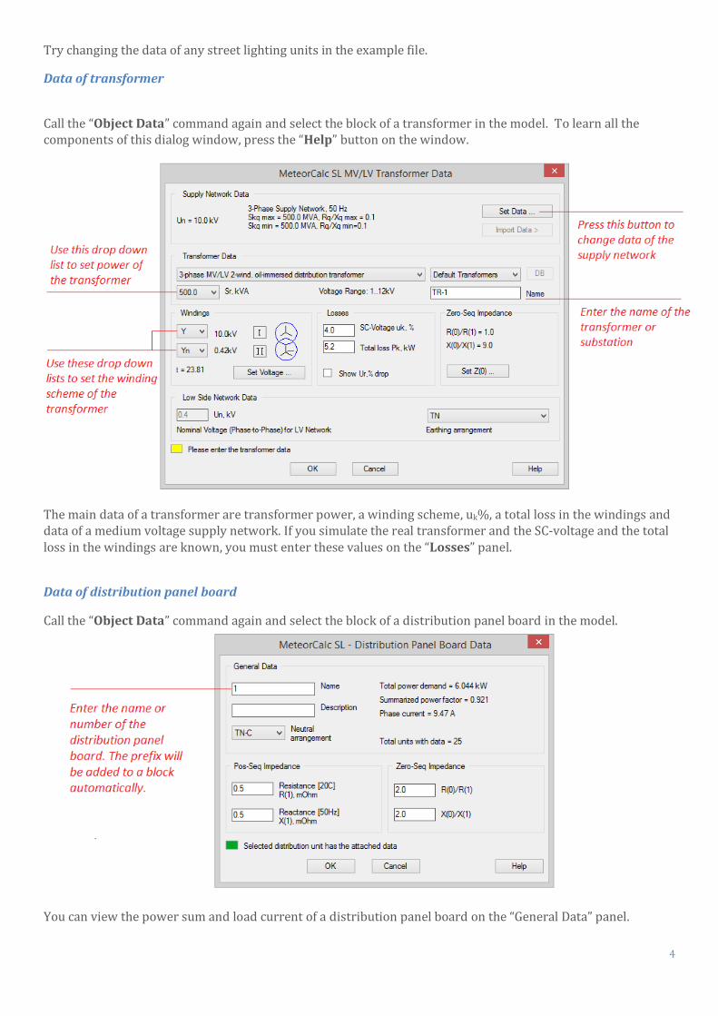
Data of transformer
Call the “Object Data” command again and select the block of a transformer in the model. To learn all the components of this dialog window, press the “Help” button on the window.
The main data of a transformer are transformer power, a winding scheme, uk%, a total loss in the windings and data of a medium voltage supply network. If you simulate the real transformer and the SC-voltage and the total loss in the windings are known, you must enter these values on the “Losses” panel.
Data of distribution panel board
Call the “Object Data” command again and select the block of a distribution panel board in the model.
You can view the power sum and load current of a distribution panel board on the “General Data” panel.
5
3. Continue creating the a street lighting model Let's try to extend the street lighting feeders in the drawing. Call the “Isolate Program Layers” command to see only the objects of the model.
Use the CAD’s “Copy” command and replicate any block of street lighting unit along the street on the plan (for example, with a step of 25m for a distance of 100-200 m in each direction). You can copy any object of a MeteorCalc SL model with data (or without data) using usual commands of a CAD platform (also you can use Copy-Paste).
Another way to extend the street lighting feeder is to insert blocks of street lighting units using the program commands “Insert Block” or “Multi Insert”. In this case, new blocks do not have any data, and you must to assign them. Use the “Object Data” command and/or the “Copy Data” command to do this.
Then you must to simulate cable spans between street lighting unit blocks. The easiest way to do it – use the “Draw Model Line” command. The polylines will be drawn on the required layer using this command. Select the start SL-block, then you may specify any number of intermediate points and finally specify a point near the end block. Joining with the end block will happen automatically.
Assign data to new cable spans. Use the “Object Data” command and/or the “Copy Data” command. Please, check that structure of extended feeders is always tree-shaped. If you use the Trial version of MeteorCalc SL, control that the number of street lighting unit blocks in the file not exceed 50 pcs.
4. Numbering of objects in a feeder and distribution them on phases Call the “Feeder Numbering” command and select the first cable of a street lighting feeder. You can number (or renumber) the street lighting units in the feeder and assign a number to the feeder only if all feeder objects have data.
You can use this command for changing the feeder number for all street lighting units in the selected feeder. Also you use this command to redistribute street lighting units in a feeder by phases.
A street light feeder usually consists of the main feeder line and several branches. After the numbering, the main line and branches have different colors. If you want to set the new main line in the feeder, select the
6
corresponding option in the “Main line detect mode” drop down list, press the “OK” button and select the end SL-unit block of the new main line.
Good! If all feeder objects have data, are numbered, distributed by phases and structure of feeders is correct, we can start electrotechnical calculations.
5. Electrotechnical calculations
MeteorCalc SL allows you to do all complicated and time-consuming calculations “by two clicks” - just select a point where you want to calculate, and then specify a point where to insert the result of calculations. “End Point Calculation” command
Use the “End Point Calculation” command to calculate the minimum SC current and voltage loss at feeder’s end points. Call this command and select the end street lighting unit block where you want to implement calculations.
Use results of this calculation to validate cross-sections of cables in the feeder line (voltage loss) and to choose a protection device of the feeder (minimum SC current). Refer to the program Help (Appendix 1) for more information about choosing protection devices of street lighting feeders.
“DPB Calculation” command
The “DPB Calculation” command is similar to the “End Point Calculation” command. The difference is that the calculations of the maximum SCC, the minimum SCC and the power sum need to be carried out separately. All results of calculations will be stored in the common result-block.
Call this command and select the distribution panel board block where you want to implement calculations. To learn all the components of this dialog window, press the “Help” button on the window.
7
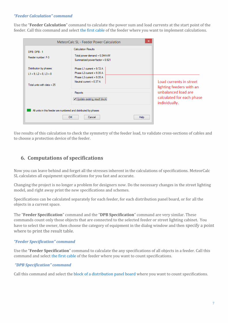
“Feeder Calculation” command
Use the “Feeder Calculation” command to calculate the power sum and load currents at the start point of the feeder. Call this command and select the first cable of the feeder where you want to implement calculations.
Use results of this calculation to check the symmetry of the feeder load, to validate cross-sections of cables and to choose a protection device of the feeder.
6. Computations of specifications
Now you can leave behind and forget all the stresses inherent in the calculations of specifications. MeteorCalc SL calculates all equipment specifications for you fast and accurate.
Changing the project is no longer a problem for designers now. Do the necessary changes in the street lighting model, and right away print the new specifications and schemes.
Specifications can be calculated separately for each feeder, for each distribution panel board, or for all the objects in a current space. The “Feeder Specification” command and the “DPB Specification” command are very similar. These commands count only those objects that are connected to the selected feeder or street lighting cabinet. You
have to select the owner, then choose the category of equipment in the dialog window and then specify a point where to print the result table. “Feeder Specification” command
Use the “Feeder Specification” command to calculate the any specifications of all objects in a feeder. Call this command and select the first cable of the feeder where you want to count specifications.
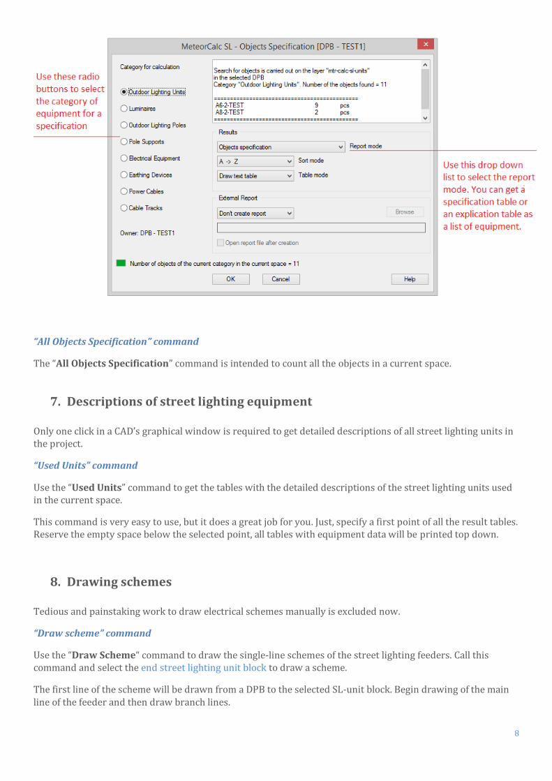
“DPB Specification” command
Call this command and select the block of a distribution panel board where you want to count specifications.
8
“All Objects Specification” command
The “All Objects Specification” command is intended to count all the objects in a current space.
7. Descriptions of street lighting equipment
Only one click in a CAD’s graphical window is required to get detailed descriptions of all street lighting units in the project.
“Used Units” command
Use the “Used Units” command to get the tables with the detailed descriptions of the street lighting units used in the current space.
This command is very easy to use, but it does a great job for you. Just, specify a first point of all the result tables. Reserve the empty space below the selected point, all tables with equipment data will be printed top down.
8. Drawing schemes Tedious and painstaking work to draw electrical schemes manually is excluded now.
“Draw scheme” command
Use the “Draw Scheme“ command to draw the single-line schemes of the street lighting feeders. Call this command and select the end street lighting unit block to draw a scheme.
The first line of the scheme will be drawn from a DPB to the selected SL-unit block. Begin drawing of the main line of the feeder and then draw branch lines.
9
The calculations of short circuit currents and voltage losses will be performed at the selected endpoint while drawing scheme, therefore the “Calculation Settings” panel is identical to the same panel on the “End Point Calculation” window.
Let’s draw the scheme of the feeder F3 main line.
Call the “Draw Scheme“ command;
Select the street lighting unit block on the end of the main line;
Check calculation conditions and scheme options in the dialog window;
Specify the first point of a scheme and then (when the scheme line is complete) specify the insertion point of the calculation result block near the scheme last block.
Continue to draw the scheme of branch lines. You must perform the above procedure for each branch. The difference is how the program determines the initial point of a branch line.
We advise you to begin to draw schemes only when the feeder configurations and all parameters of the model elements will be completely determined, but if any changes are introduced in the model of feeder, you may delete its scheme and quickly draw a new one.
10
9. Data Library of street lighting units
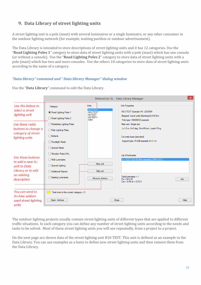
A street lighting unit is a pole (mast) with several luminaires or a single luminaire, or any other consumer in the outdoor lighting network (for example, waiting pavilion or outdoor advertisement). The Data Library is intended to store descriptions of street lighting units and it has 12 categories. Use the “Road Lighting Poles 1” category to store data of street lighting units with a pole (mast) which has one console (or without a console). Use the “Road Lighting Poles 2” category to store data of street lighting units with a pole (mast) which has two and more consoles. Use the others 10 categories to store data of street lighting units according to the name of a category.
“Data library” command and " Data library Manager” dialog window Use the “Data Library” command to edit the Data Library.
The outdoor lighting projects usually contain street lighting units of different types that are applied to different traffic situations. In each category you can define any number of street lighting units according to the needs and tasks to be solved. Most of these street lighting units you will use repeatedly, from a project to a project. On the next page are shown data of the street lighting unit B10-TEST. This unit is defined as an example in the Data Library. You can use examples as a basis to define new street lighting units and then remove them from the Data Library.
11
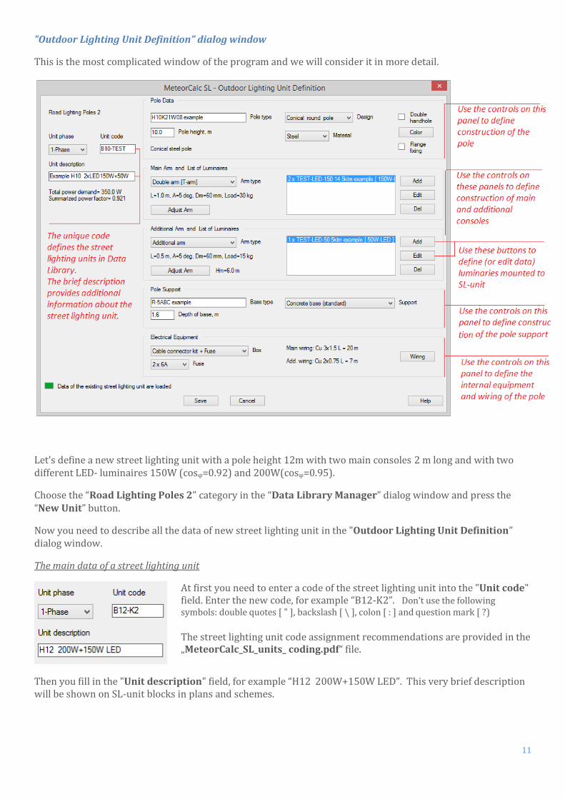
"Outdoor Lighting Unit Definition” dialog window
This is the most complicated window of the program and we will consider it in more detail.
Let’s define a new street lighting unit with a pole height 12m with two main consoles 2 m long and with two different LED- luminaires 150W (cosφ=0.92) and 200W(cosφ=0.95).
Choose the “Road Lighting Poles 2” category in the “Data Library Manager” dialog window and press the “New Unit” button.
Now you need to describe all the data of new street lighting unit in the "Outdoor Lighting Unit Definition” dialog window.
The main data of a street lighting unit
At first you need to enter a code of the street lighting unit into the "Unit code" field. Enter the new code, for example “B12-K2”. Don't use the following symbols: double quotes [ " ], backslash [ \ ], colon [ : ] and question mark [ ?)
The street lighting unit code assignment recommendations are provided in the „MeteorCalc_SL_units_ coding.pdf“ file.
Then you fill in the "Unit description" field, for example “H12 200W+150W LED”. This very brief description will be shown on SL-unit blocks in plans and schemes.
12
The “Pole Data” panel
"Pole type" field. Enter a type of the pole from a catalog or describe the pole as you want to see it in specifications. This property will be used as a basis for calculation of specifications.
"Pole height" field. Enter the height of a street lighting pole from a ground surface.
“Pole design” and “Pole material” drop down lists. Use these controls to define pole design and pole material.
Use additional controls on this panel to clarify pole construction. If the pole is painted, you can describe the color of pole surface.
The “Main Arm” and the “Additional Arm” panels
These panels are identical and are intended to describe constructions of consoles and luminaires mounted on them.
"Arm type" drop down list. Use this drop down list to select construction of console(s). The list of console constructions depends on the category.
"Adjust arm" button. Click on this button opens the "Arm Data” dialog window, where you can clarify construction of the console(s).
“List of Luminaires” list box. This field shows a list of luminaires mounted on the console(s). Select a luminaire from the list and then press the “Edit” button to view or change data of a luminaire.
Click on the “Add” or the “Edit” buttons opens the "Luminaire Data” dialog window that will be considered next.
Use the controls on the “Additional Arm” panels to define an auxiliary console and luminaires installed on it. Usually an auxiliary console is located below the main console(s). It may be a small console or a bracket for a decorative luminaire or a bracket for an additional floodlight and etc.
You can define the main and auxiliary console and install any luminaires on them. In total, you can describe 5 various types of luminaires on the SL-unit and determine 10 luminaires of each type. So, the maximum number of luminaires on a street lighting unit is 50. This is theoretical limit defined by data structure, but in practice there are usually 1-2-3, maximum 5 luminaires on a pole.
13
The “Pole Support Data” panel
"Base type" field. Enter a type of the street lighting pole support (base) from a catalog or describe the pole support as you want to see it in specifications. This property will be used as a basis for calculation of specifications.
"Depth of base" field. The height of a street lighting pole base.
"Support" drop down list. Use this drop down list to select construction of pole support (base). The “Electrical equipment” panel
"Box" drop down list. Use this drop down list to select protection devices and cable connectors mounted in the street lighting unit.
"MCB" or “Fuse” drop down list. Use this drop down list to select the rated current of the protection device.
"Wiring" button. Click on this button opens the "Internal Wiring” dialog window, where you can define the internal wiring installed in the street lighting unit.
"Luminaire Data” dialog window
14
"Luminaire type" field. Enter a type of the luminaire from a catalog or describe the luminaire as you want to see it in specifications. This property will be used as a basis for calculation of specifications.
"Light source" drop down list. Use this drop down list to select type of a lamp or type of a light source.
"Number of luminaires of this type" drop down list. If there are several identical luminaries on a SL-unit, you can describe the luminaire only one time and then set the number of them.
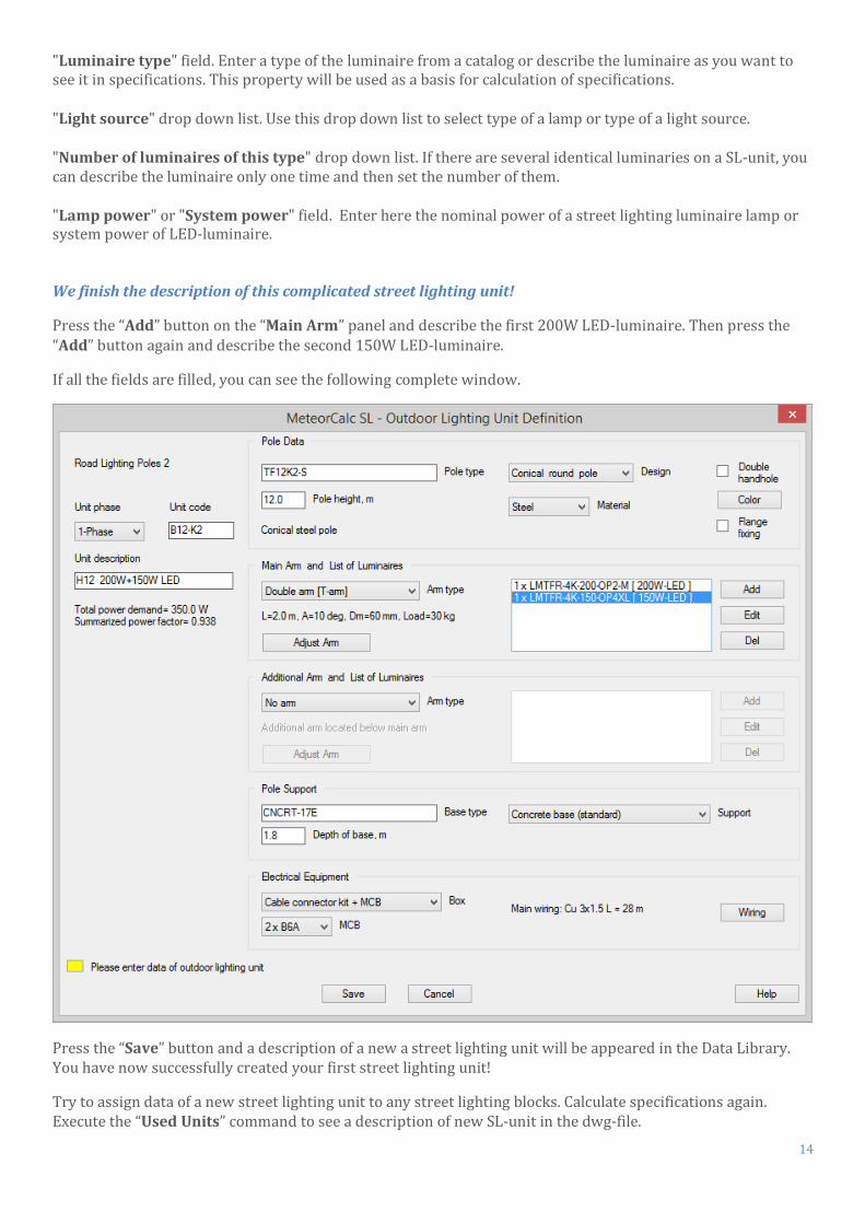
"Lamp power" or "System power" field. Enter here the nominal power of a street lighting luminaire lamp or system power of LED-luminaire. We finish the description of this complicated street lighting unit!
Press the “Add” button on the “Main Arm” panel and describe the first 200W LED-luminaire. Then press the “Add” button again and describe the second 150W LED-luminaire.
If all the fields are filled, you can see the following complete window.
Press the “Save” button and a description of a new a street lighting unit will be appeared in the Data Library. You have now successfully created your first street lighting unit!
Try to assign data of a new street lighting unit to any street lighting blocks. Calculate specifications again. Execute the “Used Units” command to see a description of new SL-unit in the dwg-file.
15
10. Summary The purpose of this guide was to show you how the MeteorCalc SL can enhance performance of a street lighting
designer. You have to perform only a small preparatory work for the creation of a street lighting model, and then you get all the benefits for automatic renumbering, data assignment and data changing, electrical calculations, obtaining specifications, drawing schemes, and so on.
We wish you productive work with the MeteorCalc SL!
11. Video tutorials and brochures
The easiest way to start with the MeteorCalc SL is to watch the video tutorials on our website https://meteorcalc.com/videos before you start to work. These videos are available on youtube too. (Please, watch in full screen mode with quality set to 1080p). All videos have English narrations. We especially recommend watching the following video: MeteorCalc SL features overview https://www.youtube.com/watch?v=1qN6aVMzKe8
Creation of a street lighting model https://www.youtube.com/watch?v=7jThjPSh53w
Audit a street lighting model https://www.youtube.com/watch?v=YIn6IzBFH2M
Data Library Manager. Add new item https://www.youtube.com/watch?v=26xxEryU594
You can find useful information papers on the https://meteorcalc.com/resources web-page.
The guidance explaining the basics of the use of the MeteorCalc SL is given in the “MeteorCalc_SL_quick_user_guide.pdf“.
The street lighting unit code assignment recommendations are provided in the „MeteorCalc_SL_units_ coding.pdf“.
We recommend use the MeteorCalc SL help system.
Please, learn the “Getting started with MeteorCalc SL” -> “Basic steps of using MeteorCalc SL” topic. For reference, use the "MeteorCalc SL Help" command or press the "Help" button in the active dialog window.
If you have any questions about the MeteorCalc SL, please, contact us . We are always ready to help you.
Note. All used in this publication trademarks belong to their respective owners.
Autodesk , the Autodesk logo, AutoCAD, DWG is a registered trademark or trademark of Autodesk, Inc., in the USA and other countries. This publication is independent of Autodesk, Inc., and is not authorized by, endorsed by, sponsored by, affiliated with, or otherwise approved by Autodesk, Inc.
BricsCAD® is commercialized by Bricsys NV. Bricsys NV is a fully owned subsidiary of Menhirs NV. All copyrights are the property of Menhirs NV. BricsCAD is a registered trademark of Bricsys NV.