CD-ROM 8280A - 1 Revision 1 December 1996 METHOD 8280A THE ANALYSIS OF POLYCHLORINATED DIBENZO-p-DIOXINS AND POLYCHLORINATED DIBENZOFURANS BY HIGH RESOLUTION GAS CHROMATOGRAPHY/LOW RESOLUTION MASS SPECTROMETRY (HRGC/LRMS) 1.0 SCOPE AND APPLICATION 1.1 This method is appropriate for the detection and quantitative measurement of 2,3,7,8- tetrachlorinated dibenzo-p-dioxin (2,3,7,8-TCDD), 2,3,7,8-tetrachlorinated dibenzofuran (2,3,7,8- TCDF), and the 2,3,7,8-substituted penta-, hexa-, hepta-, and octachlorinated dibenzo-p-dioxins (PCDDs) and dibenzofurans (PCDFs) (Figure 1) in water (at part-per-trillion concentrations), soil, fly ash, and chemical waste samples, including stillbottoms, fuel oil, and sludge matrices (at part-per- billion concentrations). The following compounds can be determined by this method (see Sec. 1.4 for a discussion of "total" concentrations). Compound CAS Registry No. 2,3,7,8-Tetrachlorodibenzo-p-dioxin (TCDD) 1746-01-6 1,2,3,7,8-Pentachlorodibenzo-p-dioxin (PeCDD) 40321-76-4 1,2,3,4,7,8-Hexachlorodibenzo-p-dioxin (HxCDD) 39227-28-6 1,2,3,6,7,8-Hexachlorodibenzo-p-dioxin (HxCDD) 57653-85-7 1,2,3,7,8,9-Hexachlorodibenzo-p-dioxin (HxCDD) 19408-74-3 1,2,3,4,6,7,8-Heptachlorodibenzo-p-dioxin (HpCDD) 35822-46-9 1,2,3,4,5,6,7,8-Octachlorodibenzo-p-dioxin (OCDD) 3268-87-9 2,3,7,8-Tetrachlorodibenzofuran (TCDF) 51207-31-9 1,2,3,7,8-Pentachlorodibenzofuran (PeCDF) 57117-41-6 2,3,4,7,8-Pentachlorodibenzofuran (PeCDF) 57117-31-4 1,2,3,4,7,8-Hexachlorodibenzofuran (HxCDF) 70648-26-9 1,2,3,6,7,8-Hexachlorodibenzofuran (HxCDF) 57117-44-9 1,2,3,7,8,9-Hexachlorodibenzofuran (HxCDF) 72918-21-9 2,3,4,6,7,8-Hexachlorodibenzofuran (HxCDF) 60851-34-5 1,2,3,4,6,7,8-Heptachlorodibenzofuran (HpCDF) 67562-39-4 1,2,3,4,7,8,9-Heptachlorodibenzofuran (HpCDF) 55673-89-7 1,2,3,4,5,6,7,8-Octachlorodibenzofuran (OCDF) 39001-02-0 Total Tetrachlorodibenzo-p-dioxin (TCDD) 41903-57-5 Total Pentachlorodibenzo-p-dioxin (PeCDD) 36088-22-9 Total Hexachlorodibenzo-p-dioxin (HxCDD) 34465-46-8 Total Heptachlorodibenzo-p-dioxin (HpCDD) 37871-00-4 Total Tetrachlorodibenzofuran (TCDF) 55722-27-5 Total Pentachlorodibenzofuran (PeCDF) 30402-15-4 Total Hexachlorodibenzofuran (HxCDF) 55684-94-1 Total Heptachlorodibenzofuran (HpCDF) 38998-75-3
Transcript
CD-ROM 8280A - 1 Revision 1December 1996
METHOD 8280A
THE ANALYSIS OF POLYCHLORINATED DIBENZO-p-DIOXINS AND POLYCHLORINATED DIBENZOFURANS BY HIGH RESOLUTION GAS
CHROMATOGRAPHY/LOW RESOLUTION MASS SPECTROMETRY (HRGC/LRMS)
1.0 SCOPE AND APPLICATION
1.1 This method is appropriate for the detection and quantitative measurement of 2,3,7,8-tetrachlorinated dibenzo-p-dioxin (2,3,7,8-TCDD), 2,3,7,8-tetrachlorinated dibenzofuran (2,3,7,8-TCDF), and the 2,3,7,8-substituted penta-, hexa-, hepta-, and octachlorinated dibenzo-p-dioxins(PCDDs) and dibenzofurans (PCDFs) (Figure 1) in water (at part-per-trillion concentrations), soil, flyash, and chemical waste samples, including stillbottoms, fuel oil, and sludge matrices (at part-per-billion concentrations). The following compounds can be determined by this method (see Sec. 1.4for a discussion of "total" concentrations).
1.2 The analytical method requires the use of high resolution gas chromatography and lowresolution mass spectrometry (HRGC/LRMS) on sample extracts that have been subjected tospecified cleanup procedures. The calibration range is dependent on the compound and the samplesize. The sample size varies by sample matrix. Table 2 lists the quantitation limits for the variousmatrices.
1.3 This method requires the calculation of the 2,3,7,8-TCDD toxicity equivalence accordingto the procedures given in the U.S. Environmental Protection Agency "Update of Toxicity EquivalencyFactors (TEFs) for Estimating Risks Associated with Exposures to Mixtures of Chlorinated Dibenzo-p-Dioxins and Dibenzofurans (CDDs/CDFs)" February 1989 (EPA 625/3-89/016). If the toxicityequivalence is greater than or equal to 0.7 ppb (soil or fly ash), 7 ppt (aqueous), or 7 ppb (chemicalwaste), analysis on a column capable of resolving all 2,3,7,8-substituted PCDDs/PCDFs isnecessary. If the expected concentrations of the PCDDs and PCDFs are below the quantitationlimits in Table 2, use of Method 8290 may be more appropriate.
1.4 This method contains procedures for reporting the total concentration of allPCDDs/PCDFs in a given level of chlorination (i.e., Total TCDD, Total PeCDF, etc.), althoughcomplete chromatographic separation of all 210 possible PCDDs/PCDFs is not possible under theinstrumental conditions described here.
1.5 This method is restricted for use only by analysts experienced with residue analysis andskilled in HRGC/LRMS. Each analyst must demonstrate the ability to generate acceptable resultswith this method.
1.6 Because of the extreme toxicity of these compounds, the analyst must take necessaryprecautions to prevent the exposure of laboratory personnel or others to materials known or believedto contain PCDDs or PCDFs. Typical infectious waste incinerators are not satisfactory devices fordisposal of materials highly contaminated with PCDDs or PCDFs. A laboratory planning to use thesecompounds should prepare a disposal plan. Additional safety instructions are outlined in Sec. 11.0.
2.0 SUMMARY OF THE METHOD
2.1 This procedure uses a matrix-specific extraction, analyte-specific cleanup, and high-resolution capillary column gas chromatography/low resolution mass spectrometry (HRGC/LRMS)techniques.
2.2 If interferants are encountered, the method provides selected cleanup procedures to aidthe analyst in their elimination. The analysis flow chart is shown at the end of this procedure.
2.3 A specified amount of water, soil, fly ash, or chemical waste samples is spiked withinternal standards and extracted according to a matrix-specific extraction procedure. Aqueoussamples are filtered, and solid samples that show an aqueous phase are centrifuged beforeextraction. The extraction procedures and solvents are:
2.3.1 Soil, fly ash, or chemical waste samples are extracted with the combination ofa Dean-Stark water trap and a Soxhlet extractor using toluene.
2.3.2 Water samples are extracted with a separatory funnel or liquid-liquid extractorusing methylene chloride.
CD-ROM 8280A - 3 Revision 1December 1996
2.4 The extracts are spiked with Cl -2,3,7,8-TCDD and submitted to an acid-base washing374
treatment, dried and concentrated. The extracts are cleaned up by column chromatography onalumina, silica gel, and activated carbon on Celite 545® and concentrated again.
2.5 An aliquot of the concentrated extract is injected into an HRGC/LRMS system capableof performing the selected ion monitoring.
2.6 The identification of the target compounds is based on their ordered elution andcomparison to standard solutions (Table 1) from an appropriate GC column and MS identification.Isomer specificity for all 2,3,7,8-substituted PCDDs/PCDFs cannot be achieved on a single column.The use of both DB-5 and SP2331 (or equivalent) columns is advised. No analyses can proceedunless all the criteria for retention times, peak identification, signal-to-noise and ion abundance ratiosare met by the GC/MS system after the initial calibration and calibration verification.
2.7 A calculation of the toxicity equivalent concentration (TEQ) of each sample is made usinginternational consensus toxicity equivalence factors (TEFs), and the TEQ is used to determine if theconcentrations of target compounds in the sample are high enough to warrant confirmation of theresults on a second GC column.
3.0 INTERFERENCES
3.1 Solvents, reagents, glassware, and other sample processing hardware may yield discreteartifacts and/or elevated baselines which may cause misinterpretation of chromatographic data. Allof these materials must be demonstrated to be free from interferents under the conditions of analysisby running laboratory method blanks.
3.2 The use of high purity reagents and pesticide grade solvents helps to minimizeinterference problems. Purification of solvents by distillation, in all glass systems, may be required.
3.3 Interferants co-extracted from the sample will vary considerably from source to source,depending upon the industrial process being sampled. PCDDs and PCDFs are often associated withother interfering chlorinated compounds such as PCBs and polychlorinated diphenyl ethers(PCDPEs) which may be found at concentrations several orders of magnitude higher than that of theanalytes of interest. Retention times of target analytes must be verified using reference standards.While certain cleanup techniques are provided as part of this method, unique samples may requireadditional cleanup techniques to achieve the sensitivity specified in this method.
3.4 High resolution capillary columns are used to resolve as many isomers as possible;however, no single column is known to resolve all of the 210 isomers. The columns employed bythe laboratory in these analyses must be capable of resolving all 17 of the 2,3,7,8-substitutedPCDDs/PCDFs sufficiently to meet the method specifications.
4.0 APPARATUS AND MATERIALS
4.1 Gas chromatograph/mass spectrometer system:
4.1.1 Gas chromatograph - An analytical system with a temperature-programmable gaschromatograph and all necessary accessories including syringes, analytical columns, andgases. The GC injection port shall be designed for capillary columns; a splitless or an on-column injection technique is recommended. A 2-µL injection volume is assumed throughout
CD-ROM 8280A - 4 Revision 1December 1996
this method; however, with some GC injection ports, other volumes may be more appropriate.A 1-µL injection volume may be used if adequate sensitivity and precision can bedemonstrated.
4.1.2 GC column - Fused silica capillary columns are needed. The columns shalldemonstrate the required separation of all 2,3,7,8-specific isomers whether a dual column ora single column analysis is chosen. Column operating conditions shall be evaluated at thebeginning and end of each 12 hour period during which samples or concentration calibrationsolutions are analyzed.
4.1.2.1 Isomer specificity for all 2,3,7,8-substituted PCDDs/PCDFs cannot beachieved on the 60 m DB-5 column. Problems have been associated with the separationof 2,3,7,8-TCDD from 1,2,3,7-TCDD and 1,2,6,8-TCDD, and separation of 2,3,7,8-TCDFfrom 1,2,4,9-, 1,2,7,9-, 2,3,4,6-, 2,3,4,7-, and 2,3,4,8-TCDF. Because of the toxicologicconcern associated with 2,3,7,8-TCDD and 2,3,7,8-TCDF, additional analyses may benecessary for some samples, as described in Sec. 7.15.8. In instances where thetoxicity equivalent concentration (TEQ) is greater than 0.7 ppb (solids), 7 ppt (aqueous),or 7 ppb (chemical waste), the reanalysis of the sample extract on a 60 m SP-2330 orSP-2331 GC, or DB-225 column (or equivalent column) may be required in order todetermine the concentrations of the individual 2,3,7,8-substituted isomers. For the DB-225 column, problems are associated with the separation of 2,3,7,8-TCDF from 2,3,4,7-TCDF and a combination of 1,2,3,9- and 2,3,4,8-TCDF.
4.1.2.2 For any sample analyzed on a DB-5 or equivalent column in which2,3,7,8-TCDF is reported as an Estimated Maximum Possible Concentration (Sec.7.15.7) that is above the quantitation limit for the matrix, analysis of the extract isrecommended on a second GC column which provides better specificity for 2,3,7,8-TCDF.
4.1.2.3 Analysis on a single column is acceptable if the required separation ofall the 2,3,7,8-specific isomers is demonstrated, and the minimum acceptance criteriaoutlined in Sec. 7.12 are met. See Sec. 7.14.5 for the specifications for the analysis ofthe 2,3,7,8-specific isomers using both dual columns and single columns.
4.2 Mass spectrometer - A low resolution instrument is employed, utilizing 70 volts (nominal)electron energy in the electron impact ionization mode. The system must be capable of selected ionmonitoring (SIM). The recommended configuration is for at least 18 ions per cycle, with a cycle timeof 1 sec or less, and a minimum integration time of 25 msec per m/z. Other cycle times andintegration times may be employed, provided that the analyst can demonstrate acceptableperformance for the calibration standards and window defining mixes. The integration time used toanalyze samples shall be identical to the time used to analyze the initial and continuing calibrationsolutions and quality control samples.
4.2.1 Interfaces - GC/MS interfaces constructed of all glass or glass-lined materials arenecessary. Glass can be deactivated by silanizing with dichlorodimethylsilane. Inserting afused silica column directly into the MS source is recommended. Care must be taken not toexpose the end of the column to the electron beam.
4.2.2 Data system - An interfaced data system is necessary to acquire, store, reduceand output mass spectral data.
CD-ROM 8280A - 5 Revision 1December 1996
4.3 Miscellaneous equipment
4.3.1 Nitrogen evaporation apparatus (N-Evap* Analytical Evaporator Model 111,Organomation Association Inc., Northborough, MA, or equivalent).
4.3.2 Balance capable of accurately weighing ±0.01 g.
4.3.3 Water bath - Equipped with concentric ring cover and temperature controlledwithin ±2EC.
4.3.4 Stainless steel (or glass) pan large enough to hold contents of 1 pint samplecontainers.
4.3.5 Glove box - For use in preparing standards from neat materials and in handlingsoil/sediment samples containing fine particulates that may pose a risk of exposure.
4.3.7 Centrifuge - Capable of operating at 400 x G with a 250-300 mL capacity.
4.3.8 Drying oven.
4.3.9 Vacuum oven - Capable of drying solvent-washed solid reagents at 110EC.
4.3.10 Mechanical shaker - A magnetic stirrer, wrist-action or platform-type shaker thatproduces vigorous agitation. Used for pre-treatment of fly ash samples.
4.4 Miscellaneous laboratory glassware
4.4.1 Extraction jars - Amber glass with polytetrafluoroethylene (PTFE)-lined screw cap;minimum capacity of approximately 200 mL; must be compatible with mechanical shaker to beused.
NOTE: The use of a solvent vapor recovery system (Kontes K-545000-1006 or K-547300-0000, Ace Glass 6614-30, or equivalent) is recommended for thepurpose of solvent recovery during the concentration procedures requiring theuse of Kuderna-Danish evaporative concentrators. Incorporation of thisapparatus may be required by State or local municipality regulations thatgovern air emissions of volatile organics. EPA recommends theincorporation of this type of reclamation system as a method to implement anemissions reduction program. Solvent recovery is a means to conform withwaste minimization and pollution prevention initiatives.
4.4.3 Disposable Pasteur pipets, 150 mm long x 5 mm ID.
4.4.4 Disposable serological pipets, 10-mL for preparation of the carbon columndescribed in Sec. 7.10.
CD-ROM 8280A - 6 Revision 1December 1996
4.4.5 Vials - 0.3-mL and 2-mL amber borosilicate glass with conical shaped reservoirand screw caps lined with PTFE-faced silicone disks.
4.4.6 Funnels - Glass; appropriate size to accommodate filter paper (12.5 cm).
4.4.7 Chromatography columns - 300 mm x 10.5 mm glass chromatographic columnfitted with PTFE stopcock.
4.4.8 Soxhlet apparatus, 500-mL flask, all glass - Complete with glass extractor body,condenser, glass extraction thimbles, heating mantle, and variable transformer for heat control.
NOTE: Extraction thimbles must be of sufficient size to hold 100 g of sand, 5 g ofsilica gel, and at least 10 g of solid sample, with room to mix the sand andsample in the thimble.
4.4.9 Dean-Stark water separator apparatus, with a PTFE stopcock. Must fit betweenSoxhlet extractor body and condenser.
4.4.11 Separatory funnels - 125-mL and 2-L separatory funnels with a PTFE stopcock.
4.4.12 Continuous liquid-liquid extractor - 1-L sample capacity, suitable for use withheavier than water solvents.
4.4.13 PTFE boiling chips - wash with hexane prior to use.
4.4.14 Buchner funnel - 15 cm.
4.4.15 Filtration flask - For use with Buchner funnel, 1-L capacity.
4.5 Filters
4.5.1 Filter paper - Whatman No. 1 or equivalent.
4.5.2 Glass fiber filter - 15 cm, for use with Buchner funnel.
4.5.3 0.7 µm, Whatman GFF, or equivalent material compatible with toluene. Rinsewith toluene.
4.6 Glass wool, silanized - Extract with methylene chloride and hexane before use.
4.7 Laboratory glassware cleaning procedures - Reuse of glassware should be minimizedto avoid the risk of using contaminated glassware. All glassware that is reused shall be scrupulouslycleaned as soon as possible after use, applying the following procedure.
4.7.1 Rinse glassware with the last solvent used in it.
4.7.2 Wash with hot water containing detergent.
4.7.3 Rinse with copious amounts of tap water and several portions of organic-freereagent water. Drain dry.
CD-ROM 8280A - 7 Revision 1December 1996
4.7.4 Rinse with pesticide grade acetone and hexane.
4.7.5 After glassware is dry, store inverted or capped with aluminum foil in a cleanenvironment.
4.7.6 Do not bake reusable glassware as a routine part of cleaning. Baking may bewarranted after particularly dirty samples are encountered, but should be minimized, asrepeated baking may cause active sites on the glass surface that will irreversibly adsorbPCDDs/PCDFs.
CAUTION: The analysis for PCDDs/PCDFs in water samples is for much lowerconcentrations than in soil/sediment, fly ash, or chemical wastesamples. Extreme care must be taken to prevent cross-contaminationbetween soil/sediment, fly ash, chemical waste and water samples.Therefore, it is strongly recommended that separate glassware bereserved for analyzing water samples.
4.8 Pre-extraction of glassware - All glassware should be rinsed or pre-extracted with solvent
immediately before use. Soxhlet-Dean-Stark (SDS) apparatus and continuous liquid-liquid extractorsshould be pre-extracted for approximately three hours immediately prior to use, using the samesolvent and extraction conditions that will be employed for sample extractions. The pooled wastesolvent for a set of extractions may be concentrated and analyzed as a method of demonstrating thatthe glassware was free of contamination.
It is recommended that each piece of reusable glassware be numbered in such a fashion thatthe laboratory can associate all reusable glassware with the processing of a particular sample. Thiswill assist the laboratory in:
1) Tracking down possible sources of contamination for individual samples,
2) Identifying glassware associated with highly contaminated samples that may requireextra cleaning, and
3) Determining when glassware should be discarded.
5.0 REAGENTS
5.1 Solvents - all solvents must be pesticide grade, distilled-in-glass.
5.1.1 Hexane, C H6 14
5.1.2 Methanol, CH OH3
5.1.3 Methylene chloride, CH Cl2 2
5.1.4 Toluene, C H CH6 5 3
5.1.5 Isooctane, (CH ) CCH CH(CH )3 3 2 3 2
5.1.6 Cyclohexane, C H6 12
CD-ROM 8280A - 8 Revision 1December 1996
5.1.7 Acetone, CH COCH3 3
5.1.8 Tridecane, CH (CH ) CH3 2 11 3
5.1.9 Nonane, C H9 20
5.2 White quartz sand - 60/70 mesh, for use in the Soxhlet-Dean-Stark (SDS) extractor.Bake at 450EC for 4 hours minimum.
5.3 Sodium sulfate (granular, anhydrous), Na SO - Purify by heating at 400EC for 4 hours2 4
in a shallow tray, or by extracting with methylene chloride. If, after heating, the sodium sulfatedevelops a noticeable grayish cast (due to the presence of carbon in the crystal matrix) that batchof sodium sulfate is not suitable for use and should be discarded. Extraction with methylene chloridemay produce sodium sulfate that is suitable for use in such instances, but following extraction, areagent blank must be analyzed that demonstrates that there is no interference from the sodiumsulfate.
5.4 Potassium hydroxide, KOH - ACS reagent grade, prepare a 20% (w/v) solution in organic-free reagent water.
5.5 Sulfuric acid, H SO , concentrated - ACS reagent grade, specific gravity 1.84.2 4
5.6 Sodium chloride, NaCl - ACS reagent grade, prepare a 5% (w/v) solution in organic-freereagent water.
5.7 Hydrochloric acid, HCl, concentrated - ACS reagent grade, specific gravity 1.17. Preparea 1N solution in organic-free reagent water for pretreatment of fly ash samples.
5.8 Column chromatography reagents
This section describes the column chromatography reagents employed in this method forcleanup of sample extracts. The quality of two of these reagents, the alumina and silica gel, iscritical to a successful analysis. Prior to employing the reagents in Secs. 5.8.1., 5.8.4., 5.8.5., and5.8.6., the analyst should demonstrate that they meet the performance requirements in Sec. 7.9.2.
5.8.1 Alumina, acidic - Supelco 19996-6C (or equivalent). Soxhlet extract withmethylene chloride for 18 hours and activate by heating to 130EC for a minimum of 12 hours.
5.8.2 Charcoal carbon - Activated carbon, Carbopak C (Supelco) or equivalent,prewashed with methanol and dried in vacuo at 110EC. (Note: AX-21 [Anderson DevelopmentCompany] carbon is no longer available, but existing stocks may be utilized).
5.8.3 Celite 545 (Supelco) or equivalent.
5.8.4 Silica gel - High-purity grade, type 60, 70-230 mesh. Soxhlet extract withmethylene chloride for 21 hours and activate by heating in a foil covered glass container for24 hours at 190EC.
5.8.5 Silica gel impregnated with 2% (w/w) sodium hydroxide - Add one part by weightof 1 M NaOH solution to two parts silica gel (extracted and activated) in a screw-cap bottle andmix with a glass rod until free of lumps.
CD-ROM 8280A - 9 Revision 1December 1996
5.8.6 Silica gel impregnated with 40% (w/w) sulfuric acid. Add two parts by weightconcentrated sulfuric acid to three parts silica gel (extracted and activated), mix with a glassrod until free of lumps, and store in a screw-cap glass bottle.
5.9 Calibration solutions (Table 1) - Prepare five tridecane (or nonane) solutions (CC1-CC5)containing 10 unlabeled and 7 carbon-labeled PCDDs/PCDFs at known concentrations for use ininstrument calibration. One of these five solutions (CC3) is used as the calibration verificationsolution and contains 7 additional unlabeled 2,3,7,8-isomers. The concentration ranges arehomologue-dependent, with the lowest concentrations associated with tetra- and pentachlorinateddioxins and furans (0.1 to 2.0 ng/µL), and the higher concentrations associated with the hexa-through octachlorinated homologues (0.5 to 10.0 ng/µL). Commercially-available standardscontaining all 17 unlabeled analytes in each solution may also be utilized.
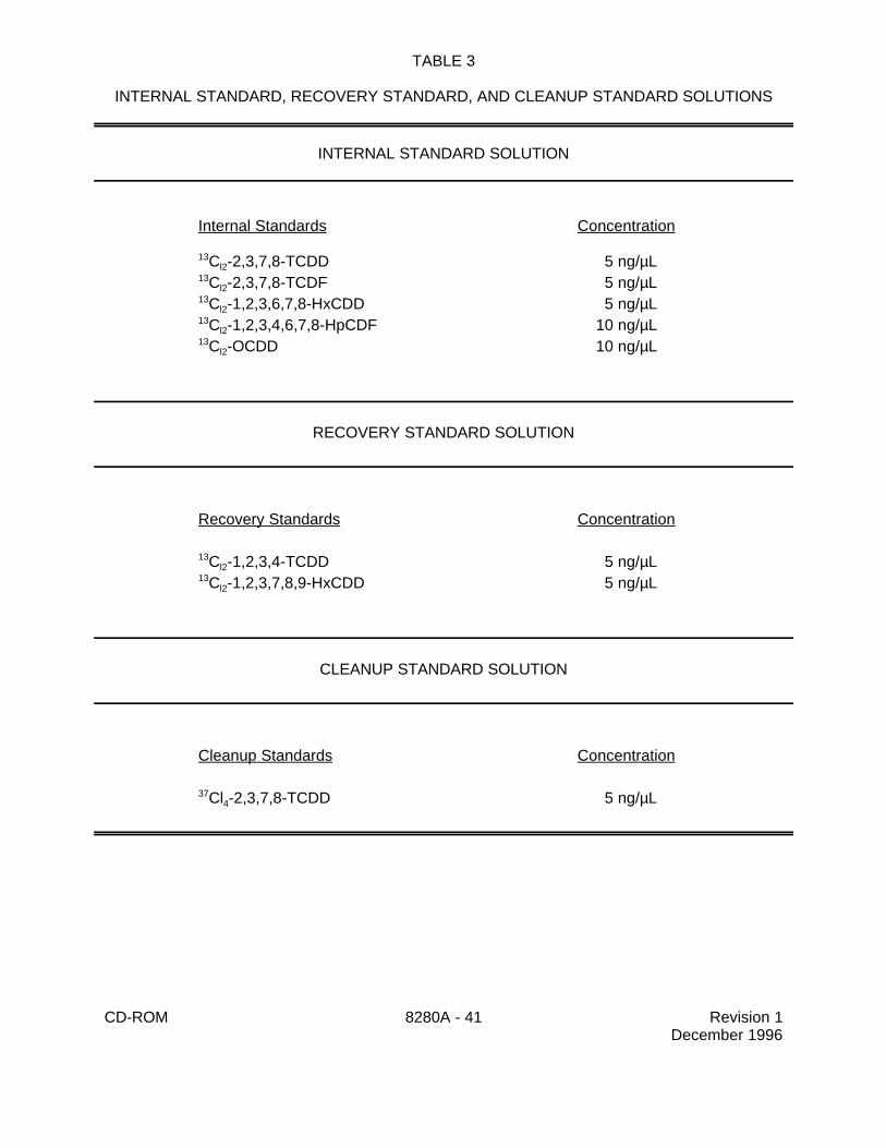
5.10 Internal standard solution (Table 3) - Prepare a solution containing the five internalstandards in tridecane (or nonane) at the nominal concentrations listed in Table 3. Mix 10 µL with1.0 mL of acetone before adding to each sample and blank.
5.11 Recovery standard solution (Table 3) - Prepare a solution in hexane containing therecovery standards, C -1,2,3,4-TCDD and C -1,2,3,7,8,9-HxCDD, at concentrations of 5.0 ng/µL,13 13
12 12
in a solvent other than tridecane or nonane.
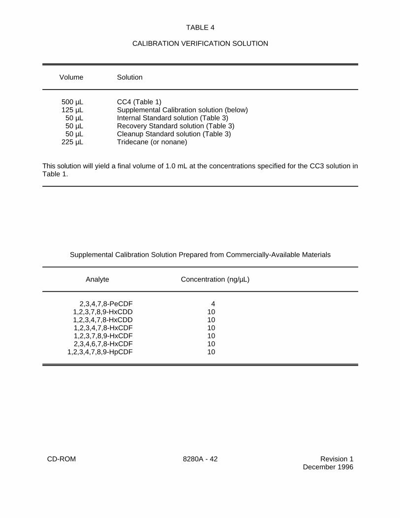
5.12 Calibration verification solution - Prepare a solution containing standards to be used foridentification and quantitation of target analytes (Table 4).
5.13 Cleanup standard - Prepare a solution containing Cl -2,3,7,8-TCDD at a concentration374
of 5 ng/µL (5 µg/mL) in tridecane (or nonane). Add this solution to all sample extracts prior tocleanup. The solution may be added at this concentration, or diluted into a larger volume of solvent.The recovery of this compound is used to judge the efficiency of the cleanup procedures.
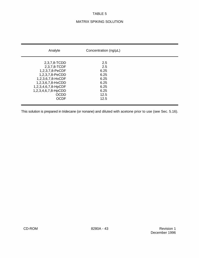
5.14 Matrix spiking standard - Prepare a solution containing ten of the 2,3,7,8-substitutedisomers, at the concentrations listed in Table 5 in tridecane (or nonane). Use this solution to preparethe spiked sample aliquot. Dilute 10 µL of this standard to 1.0 mL with acetone and add to thealiquot chosen for spiking.
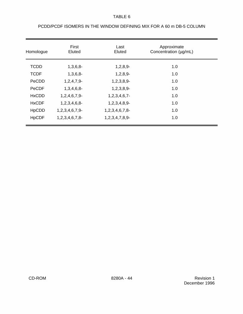
5.15 Window defining mix - Prepare a solution containing the first and last eluting isomer ofeach homologue (Table 6). Use this solution to verify that the switching times between thedescriptors have been appropriately set.
5.16 Column performance solutions
Chromatographic resolution is verified using a test mixture of PCDDs/PCDFs specific toeach column show below.
DB-5 test mix: 1,2,3,7-TCDD/1,2,3,8-TCDD2,3,7,8-TCDD1,2,3,9-TCDD
DB-225 test mix: 2,3,4,7-TCDF2,3,7,8-TCDF1,2,3,9-TCDF
CD-ROM 8280A - 10 Revision 1December 1996
SP-2331 test mix: 2,3,7,8-TCDD1,4,7,8-TCDD1,2,3,7-TCDD1,2,3,8-TCDD
The concentrations of these isomers should be approximately 0.5 ng/µL in tridecane (ornonane).
If the laboratory employs a column that has a different elution order than those specified here,the laboratory must ensure that the isomers eluting closest to 2,3,7,8-TCDD are represented in thecolumn performance solution.
6.0 SAMPLE COLLECTION, HANDLING, AND PRESERVATION
6.1 See the introductory material to this chapter, Organic Analytes.
6.2 Sample collection
6.2.1 Sample collection personnel should, to the extent possible, homogenize samplesin the field before filling the sample containers. This should minimize or eliminate the necessityfor sample homogenization in the laboratory. The analyst should make a judgment, based onthe appearance of the sample, regarding the necessity for additional mixing. If the sample isclearly not homogeneous, the entire contents should be transferred to a glass or stainless steelpan for mixing with a stainless steel spoon or spatula before removal of a sample portion foranalysis.
6.2.2 Grab and composite samples must be collected in glass containers.Conventional sampling practices must be followed. The bottle must not be prewashed withsample before collection. Sampling equipment must be free of potential sources ofcontamination.
6.2.3 If residual chlorine is present in aqueous samples, add 80 mg sodium thiosulfateper liter of sample. If sample pH is greater than 9, adjust to pH 7-9 with sulfuric acid.
6.3 Storage and holding times - All samples should be stored at 4EC in the dark, extractedwithin 30 days and completely analyzed within 45 days of extraction. Whenever samples areanalyzed after the holding time expiration date, the results should be considered to be minimumconcentrations and should be identified as such.
NOTE: The holding times listed in Sec. 6.3 are recommendations. PCDDs and PCDFsare very stable in a variety of matrices, and holding times under the conditionslisted in Sec. 6.3 may be as high as a year for certain matrices. Sample extracts,however, should always be analyzed within 45 days of extraction.
7.0 PROCEDURE
Four types of extraction procedures are employed in these analyses, depending on the samplematrix.
1) Chemical waste samples are extracted by refluxing with a Dean-Stark water separator.
CD-ROM 8280A - 11 Revision 1December 1996
2) Fly ash samples and soil/sediment samples are extracted in a combination of a Soxhletextractor and a Dean-Stark water separator.
3) Water samples are filtered and then the filtrate is extracted using either a separatoryfunnel procedure or a continuous liquid-liquid extraction procedure.
4) The filtered particulates are extracted in a combination of a Soxhlet extractor and aDean-Stark water separator.
Sec. 7.1 provides general information on the use of the Soxhlet-Dean-Stark apparatus. The fourmatrix-specific extraction procedures are described in Secs. 7.2 - 7.5.
7.1 General considerations for use of the Soxhlet-Dean-Stark (SDS) apparatus - Thefollowing procedures apply to use of the SDS apparatus for extracting matrices covered by thisprotocol.
The combination of a Soxhlet extractor and a Dean-Stark trap is used for the removal of waterand extraction of PCDDs/PCDFs from samples of fly ash, soil/sediment, and the particulate fractionof water samples.
For soil/sediment samples, the results of these analyses are reported based on the wet weightof the sample. However, use of the SDS allows the water content of a sample to be determinedfrom the same aliquot of sample that is also extracted for analysis. The amount of water evolvedfrom the sample during extraction is used to approximate the percent solids content of the sample.The percent solids data may be employed by the data user to approximate the dry weightconcentrations. The percent solids determination does not apply to the extraction of particulatesfrom the filtration of water samples or to the extraction of fly ash samples which are treated with anHCl solution prior to extraction.
7.1.1 The extraction of soil/sediment, fly ash, and particulates from water samples willrequire the use of a Soxhlet thimble. See Sec. 4.6 for a discussion of pre-extraction ofglassware such as the SDS. Prior to pre-extraction, prepare the thimble by adding 5 g of70/230 mesh silica gel to the thimble to produce a thin layer in the bottom of the thimble. Thislayer will trap fine particles in the thimble. Add 80-100 g of quartz sand on top of the silica gel,and place the thimble in the extractor.
7.1.2 Pre-extract the SDS for three hours with toluene, then allow the apparatus to cooland remove the thimble. Mix the appropriate weight of sample with the sand in the thimble,being careful not to disturb the silica gel layer.
7.1.3 If the sample aliquot to be extracted contains large lumps, or is otherwise noteasily mixed in the thimble, the sand and sample may be mixed in another container. Transferapproximately 2/3 of the sand from the thimble to a clean container, being careful not to disturbthe silica gel layer when transferring the sand. Thoroughly mix the sand with the sample witha clean spatula, and transfer the sand/sample mixture to the thimble.
7.1.4 If a sample with particularly high moisture content is to be extracted, it may behelpful to leave a small conical depression in the material in the thimble. This will allow thewater to drain through the thimble more quickly during the early hours of the extraction. As themoisture is removed during the first few hours of extraction, the depression will collapse, andthe sample will be uniformly extracted.
CD-ROM 8280A - 12 Revision 1December 1996
7.2 Chemical waste extraction (including oily sludge/wet fuel oil and stillbottom/oil).
7.2.1 Assemble a flask, a Dean-Stark trap, and a condenser, and pre-extract withtoluene for three hours (see Sec. 4.6). After pre-extraction, allow the apparatus to cool, anddiscard the used toluene, or pool it for later analysis to verify the cleanliness of the glassware.
7.2.2 Weigh about 1 g of the waste sample to two decimal places into a tared pre-extracted 125-mL flask. Add 1 mL of the acetone-diluted internal standard solution (Sec. 5.10)to the sample in the flask. Attach the pre-extracted Dean-Stark water separator and condenserto the flask, and extract the sample by refluxing it with 50 mL of toluene for at least three hours.
Continue refluxing the sample until all the water has been removed. Cool the sample,
filter the toluene extract through a rinsed glass fiber filter into a 100-mL round bottom flask.Rinse the filter with 10 mL of toluene; combine the extract and rinsate. Concentrate thecombined solution to approximately 10 mL using a K-D or rotary evaporator as described inSecs. 7.6.1 and 7.6.2. Transfer the concentrated extract to a 125-mL separatory funnel. Rinsethe flask with toluene and add the rinse to the separatory funnel. Proceed with acid-basewashing treatment per Sec. 7.7, the micro-concentration per Sec. 7.8, the chromatographicprocedures per Secs. 7.9 and 7.10, and a final concentration per Sec. 7.11.
7.2.3 Prepare an additional two 1-g aliquots of the sample chosen for spiking. Afterweighing the sample in a tared pre-extracted flask (Sec. 7.2.2), add 1.0 mL of the acetone-diluted matrix spiking standard solution (Sec. 5.14) to each of the two aliquots. After allowingthe matrix spiking solution to equilibrate to approximately 1 hour, add the internal standardsolution and extract the aliquots as described in Sec. 7.2.2.
7.3 Fly ash sample extraction
7.3.1 Weigh about 10 g of the fly ash to two decimal places, and transfer to anextraction jar. Add 1 mL of the acetone-diluted internal standard solution to the sample.
7.3.2 Add 150 mL of 1 N HCl to the fly ash sample in the jar. Seal the jar with thePTFE-lined screw cap, place on a mechanical shaker, and shake for 3 hours at roomtemperature.
7.3.3 Rinse a Whatman #1 (or equivalent) filter paper with toluene, and then filter thesample through the filter paper in a Buchner funnel into a 1 L receiving flask. Wash the fly ashwith approximately 500 mL of organic-free reagent water.
7.3.4 Mix the fly ash with the sand in the pre-extracted thimble (Sec. 7.1.2). Place thefilter paper from Sec. 7.3.3 on top of the sand. Place the thimble in a SDS extractor, add 200mL toluene, and extract for 16 hours. The solvent should cycle completely through the system5-10 times per hour. Cool and filter the toluene extract through a rinsed glass fiber filter intoa 500-mL round-bottom flask. Rinse the filter with 10 mL of toluene. Concentrate the extractas described in Secs. 7.6.1 or 7.6.2. Transfer the concentrated extract to a 125-mL separatoryfunnel. Rinse the flask with toluene and add the rinse to the separatory funnel. Proceed withacid-base washing treatment per Sec. 7.7, the micro-concentration per Sec. 7.8, thechromatographic procedures per Secs. 7.9 and 7.10 and a final concentration per Sec. 7.11.
NOTE: A blank should be analyzed using a piece of filter paper handled in the samemanner as the fly ash sample.
Percent solids 'Wet weight of sample & Weight of water
Wet weight of samplex 100
CD-ROM 8280A - 13 Revision 1December 1996
7.3.5 Prepare an additional two 10-g aliquots of the sample chosen for spiking for useas the matrix spike and matrix spike duplicate. Transfer each aliquot to a separate extractionjar and add 1.0 mL of the acetone-diluted matrix spiking standard solution (Sec. 5.14) to eachof the two aliquots. After allowing the matrix spiking solution to equilibrate to approximately1 hour, add the internal standard solution and extract the aliquots as described in Sec. 7.3.1.
7.4 Soil/sediment sample extraction
NOTE: Extremely wet samples may require centrifugation to remove standing waterbefore extraction.
7.4.1 Weigh about 10 grams of the soil to two decimal places and transfer to a pre-extracted thimble (Sec. 7.1.2). Mix the sample with the quartz sand, and add 1 mL of theacetone-diluted internal standard solution (Sec. 5.10) to the sample/sand mixture. Add smallportions of the solution at several sites on the surface of the sample/sand mixture.
7.4.2 Place the thimble in the SDS apparatus, add 200 to 250 mL toluene, and refluxfor 16 hours. The solvent should cycle completely through the system 5-10 times per hour.
7.4.3 Estimate the percent solids content of the soil/sediment sample by measuring thevolume of water evolved during the SDS extraction procedure. For extremely wet samples,the Dean-Stark trap may need to be drained one or more times during the 16-hour extraction.Collect the water from the trap, measure its volume to the nearest 0.1 mL. Assume a densityof 1.0 g/mL, and calculate the percent solids content according to the formula below:
7.4.4 Concentrate this extract as described in Secs. 7.6.1 or 7.6.2. Transfer theconcentrated extract to a 125 mL separatory funnel. Rinse the flask with toluene and add therinse to the separatory funnel. Proceed with acid-base washing treatment per Sec. 7.7, themicro concentration per Sec. 7.8, the chromatographic procedures per Secs. 7.9 and 7.10 anda final concentration per Sec. 7.11.
7.4.5 Prepare an additional two 10-g aliquots of the sample chosen for spiking for useas the matrix spike and matrix spike duplicate. After transferring each aliquot to a separatepre-extracted Soxhlet thimble, add 1.0 mL of the acetone-diluted matrix spiking standardsolution (Sec. 5.14) to each of the two aliquots. After allowing the matrix spiking solution toequilibrate to approximately 1 hour, add the internal standard solution (Sec. 5.10) and extractthe aliquots as described in Sec. 7.4.1.
7.5 Aqueous sample extraction
7.5.1 Allow the sample to come to ambient temperature, then mark the water meniscuson the side of the 1-L sample bottle for determination of the exact sample volume.
7.5.2 Add 1 mL of the acetone-diluted internal standard solution (Sec. 5.10) to thesample bottle. Cap the bottle, and mix the sample by gently shaking for 30 seconds.
7.5.3 Filter the sample through a 0.7-µm filter that has been rinsed with toluene.Collect the aqueous filtrate in a clean flask. If the total dissolved and suspended solids
CD-ROM 8280A - 14 Revision 1December 1996
contents are too much to filter through the 0.7-µm filter, centrifuge the sample, decant, andthen filter the aqueous phase. Alternatively, other filter configurations, including stacked filtersof decreasing pore sizes, may be employed. Procedures for extraction of the particulatefraction are given in Sec. 7.5.4. The aqueous portion may be extracted using either theseparatory funnel technique (Sec. 7.5.5.1) or a pre-extracted continuous liquid-liquid extractor(Sec. 7.5.5.2).
NOTE: Organic-free reagent water used as a blank must also be filtered in a similarfashion, and subjected to the same cleanup and analysis as the watersamples.
7.5.4 Particulate fraction
7.5.4.1 Combine the particulate on the filter and the filter itself, and ifcentrifugation was used, the solids from the centrifuge bottle(s), with the quartz sand inthe pre-extracted Soxhlet thimble. Place the filter on top of the particulate/sand mixture,and place the thimble into a pre-extracted SDS apparatus.
7.5.4.2 Add 200 to 250 mL of toluene to the SDS apparatus and reflux for16 hours. The solvent should cycle completely through the system 5-10 times per hour.
7.5.4.3 Allow the Soxhlet to cool, remove the toluene and concentrate thisextract as described in Secs. 7.6.1. or 7.6.2.
7.5.5 Aqueous filtrate
The aqueous filtrate may be extracted by either a separatory funnel procedure (Sec.7.5.5.1) or a continuous liquid-liquid extraction procedure (Sec. 7.5.5.2).
7.5.5.1 Separatory funnel extraction - Pour the filtered aqueous sample intoa 2-L separatory funnel. Add 60 mL methylene chloride to the sample bottle, seal, andshake 60 seconds to rinse the inner surface. Transfer the solvent to the separatoryfunnel and extract the sample by shaking the funnel for 2 minutes with periodic venting.Allow the organic layer to separate from the water phase for a minimum of 10 minutes.Drain the methylene chloride extract into a 500-mL K-D concentrator (mounted with a 10-mL concentrator tube) by passing the extract through a funnel packed with a glass woolplug and half-filled with anhydrous sodium sulfate. Extract the water sample two moretimes using 60 mL of fresh methylene chloride each time. Drain each extract through thefunnel into the K-D concentrator. After the third extraction, rinse the sodium sulfate withat least 30 mL of fresh methylene chloride. Concentrate this extract as described inSecs. 7.6.1 or 7.6.2.
7.5.5.2 Continuous liquid-liquid extraction - A continuous liquid-liquidextractor may be used in place of a separatory funnel when experience with a samplefrom a given source indicates that a serious emulsion problem will result or an emulsionis encountered using a separatory funnel. The following procedure is used for acontinuous liquid-liquid extractor.
7.5.5.2.1 Pre-extract the continuous liquid-liquid extractor forthree hours with methylene chloride and reagent water. Allow the extractor tocool, discard the methylene chloride and the reagent water, and add the filtered
CD-ROM 8280A - 15 Revision 1December 1996
aqueous sample to the continuous liquid-liquid extractor. Add 60 mL ofmethylene chloride to the sample bottle, seal and shake for 30 seconds.
7.5.5.2.2 Transfer the solvent to the extractor. Repeat thesample bottle rinse with an additional 50 to 100 mL portion of methylene chlorideand add the rinse to the extractor. Add 200 to 500 mL methylene chloride to thedistilling flask and sufficient reagent water to ensure proper operation. Extractfor 16 hours. Allow to cool, then detach the flask and dry the sample by runningit through a rinsed funnel packed with a glass wool plug and 5 g of anhydroussodium sulfate into a 500-mL K-D flask. Concentrate the extract according toSecs. 7.6.1 or 7.6.2.
7.5.6 Combination of extracts - The extracts from both the particulate fraction (Sec.7.5.4) and the aqueous filtrate (Sec. 7.5.5) must be concentrated using the procedures in Sec.7.6.1 and then combined together prior to the acid-base washing treatment in Sec. 7.7.
7.5.7 Determine the original aqueous sample volume by refilling the sample bottle tothe mark and transferring the liquid to a 1-L graduated cylinder. Record the sample volumeto the nearest 5 mL.
7.5.8 Prepare an additional two 1-L aliquots of the sample chosen for spiking for useas the matrix spike and matrix spike duplicate. Add 1.0 mL of the acetone-diluted matrixspiking standard solution (Sec. 5.14) to each of the two aliquots in the original sample bottles.After allowing the matrix spiking solution to equilibrate to approximately 1 hour, add the internalstandard solution and filter and extract the aliquots as described in Sec. 7.5.2.
7.6 Macro-concentration procedures (all matrices)
Prior to cleanup, extracts from all matrices must be concentrated to approximately 10 mL. Inaddition, as noted above, the concentrated extracts from the aqueous filtrate and the filteredparticulates must be combined prior to cleanup. Two procedures may be used for macro-concentration, rotary evaporator, or Kuderna-Danish (K-D). Concentration of toluene by K-D involvesthe use of a heating mantle, as toluene boils above the temperature of a water bath. The twoprocedures are described below.
7.6.1 Concentration by K-D
7.6.1.1 Add one or two clean boiling chips to the flask and attach a three-ball Snyder column. Pre-wet the column by adding approximately 1 mL of toluenethrough the top.
7.6.1.2 Attach the solvent recovery system condensor, place the roundbottom flask in a heating mantle and apply heat as required to complete theconcentration in 15-20 minutes. At the proper rate of distillation, the balls of the columnwill actively chatter but the chambers will not flood.
7.6.1.3 When the apparent volume of liquid reaches 10 mL, remove the K-Dapparatus from the water bath and allow it to drain and cool for at least 10 minutes.
CD-ROM 8280A - 16 Revision 1December 1996
7.6.2 Concentration by rotary evaporator
7.6.2.1 Assemble the rotary evaporator according to manufacturer'sinstructions, and warm the water bath to 45EC. On a daily basis, preclean the rotaryevaporator by concentrating 100 mL of clean extraction solvent through the system.Archive both the concentrated solvent and the solvent in the catch flask forcontamination check if necessary. Between samples, three 2-3 mL aliquots of tolueneshould be rinsed down the feed tube into a waste beaker.
7.6.2.2 Attach the round bottom flask containing the sample extract to therotary evaporator. Slowly apply vacuum to the system and begin rotating the sampleflask. Lower the sample flask into the water bath and adjust the speed of rotation tocomplete the concentration in 15-20 minutes. At the proper rate of concentration, theflow of condensed solvent into the receiving flask will be steady, but no bumping orvisible boiling will occur.
7.6.2.3 When the apparent volume of the liquid reaches 10 mL, shut off thevacuum and the rotation. Slowly admit air into the system, taking care not to splash theextract out of the sample flask.
7.7 Micro-concentration procedures (all matrices)
When further concentration is required, either a micro-Snyder column technique or anitrogen evaporation technique is used to adjust the extract to the final volume required.
7.7.1 Micro-Snyder column technique
7.7.1.1 Add another one or two clean boiling chips to the concentrator tubeand attach a two-ball micro-Snyder column. Prewet the column by adding about 0.5 mLof toluene to the top of the column.
7.7.1.2 Place the round bottom flask in a heating mantle and apply heat asrequired to complete the concentration in 5-10 minutes. At the proper rate of distillationthe balls of the column will actively chatter, but the chambers will not flood.
7.7.1.3 When the apparent volume of liquid reaches 0.5 mL, remove the K-D apparatus from the water bath and allow it to drain and cool for at least 10 minutes.Remove the Snyder column and rinse the flask and its lower joints with about 0.2 mL ofsolvent and add to the concentrator tube. Adjust the final volume to 1.0 mL with solvent.
7.7.2 Nitrogen blowdown technique
7.7.2.1 Place the concentrator tube in a warm water bath (approximately35EC) and evaporate the solvent volume to the required level using a gentle stream ofclean, dry nitrogen (filtered through a column of activated carbon).
CAUTION: Do not use plasticized tubing between the carbon trap and thesample.
7.7.2.2 The internal wall of the tube must be rinsed down several times withthe appropriate solvent during the operation. During evaporation, the solvent level in thetube must be positioned to prevent water from condensing into the sample (i.e., the
CD-ROM 8280A - 17 Revision 1December 1996
solvent level should be below the level of the water bath). Under normal operatingconditions, the extract should not be allowed to become dry.
7.7.2.3 When the apparent volume of liquid reaches 0.5 mL, remove theconcentrator tube from the water bath. Adjust the final volume to 1.0 mL with solvent.
7.8 Acid-base cleanup procedure (all matrices)
7.8.1 The concentrated extracts from all matrices are subjected to a series of cleanupprocedures generally beginning with an acid-base wash, and continuing on with silica gelchromatography, alumina chromatography, and carbon chromatography. The acid-base washmay not be necessary for uncolored extracts, but all the other cleanup procedures should beemployed, regardless of the color of the extract. Begin the cleanup procedures byquantitatively transferring each concentrated extract to a separate 125-mL separatory funnel.
7.8.2 Prior to cleanup, all extracts are spiked with the Cl -2,3,7,8-TCDD cleanup374
standard (Sec. 5.13). The recovery of this standard is used to monitor the efficiency of thecleanup procedures. Spike 5 µL of the cleanup standard (or a larger volume of diluted solutioncontaining 25 ng of Cl -2,3,7,8-TCDD) into each separatory funnel containing an extract,37
4
resulting in a concentration of 0.25 ng/µL in the final extract analyzed by GC/MS.
CAUTION: Concentrated acid and base produce heat when mixed with aqueoussolutions, and may cause solutions to boil or splatter. Perform thefollowing extractions carefully, allowing the heat and pressure in theseparatory funnel to dissipate before shaking the stoppered funnel.
7.8.3 Partition the concentrated extract against 40 mL of concentrated sulfuric acid.Shake for 2 minutes. Remove and discard the acid layer (bottom). Repeat the acid washinguntil no color is visible in the acid layer. (Perform acid washing a maximum of 4 times.)
7.8.4 Partition the concentrated extract against 40 mL of 5 percent (w/v) sodiumchloride. (Caution: Acid entrained in the extract may produce heat when mixed with thesodium chloride solution). Shake for two minutes. Remove and discard the aqueous layer(bottom).
7.8.5 Partition the concentrated extract against 40 mL of 20 percent (w/v) potassiumhydroxide (KOH). (Caution: Allow heat to dissipate before shaking). Shake for 2 minutes.Remove and discard the base layer (bottom). Repeat the base washing until color is notvisible in the bottom layer (perform base washing a maximum of four times). Strong base(KOH) is known to degrade certain PCDDs/PCDFs; therefore, contact time should beminimized.
7.8.6 Partition the concentrated extract against 40 mL of 5 percent (w/v) sodiumchloride. (Caution: Base entrained in the extract may produce heat when mixed with thesodium chloride solution). Shake for 2 minutes. Remove and discard the aqueous layer(bottom). Dry the organic layer by pouring it through a funnel containing a rinsed filter half-filledwith anhydrous sodium sulfate. Collect the extract in an appropriate size (100- to 250-mL)round bottom flask. Wash the separatory funnel with two 15-mL portions of hexane, pourthrough the funnel and combine the extracts.
7.8.7 Concentrate the extracts of all matrices to 1.0 mL of hexane using the proceduresdescribed in Sec. 7.7. Solvent exchange is accomplished by concentrating the extract to
CD-ROM 8280A - 18 Revision 1December 1996
approximately 100 µL, adding 2-3 mL of hexane to the concentrator tube and continuingconcentration to a final volume of 1.0 mL.
7.9 Silica gel and alumina column chromatographic procedures
7.9.1 Silica gel column - Insert a glass wool plug into the bottom of a gravity column (1cm x 30 cm glass column) fitted with a PTFE stopcock. Add 1 g silica gel and tap the columngently to settle the silica gel. Add 2 g sodium hydroxide-impregnated silica gel, 1 g silica gel,4 g sulfuric acid-impregnated silica gel, and 2 g silica gel (Sec. 5.8). Tap the column gentlyafter each addition. A small positive pressure (5 psi) of clean nitrogen may be used if needed.
7.9.2 Alumina column - Insert a glass wool plug onto the bottom of a gravity column (1cm x 30 cm glass column) fitted with a PTFE stopcock. Add 6 g of the activated acid alumina(Sec. 5.8.1). Tap the top of the column gently.
NOTE: Check each new batch of silica gel and alumina by combining 50 µL of thecontinuing calibration solution (CC3) with 950 µL of hexane. Process thissolution through both columns in the same manner as a sample extract(Secs. 7.9.5 through 7.9.9). Concentrate the continuing calibration solutionto a final volume of 50 µL. Proceed to Sec. 7.14. If the recovery of any ofthe analytes is less than 80%, the batch of alumina or silica gel may not beappropriate for use.
7.9.3 Add hexane to each column until the packing is free of air bubbles. A smallpositive pressure (5 psi) of clean dry nitrogen may be used if needed. Check the columns forchanneling. If channeling is present, discard the column. Do not tap a wetted column.
7.9.4 Assemble the two columns such that the eluate from the silica gel column drainsdirectly into the alumina column. Alternatively, the two columns may be eluted separately.
7.9.5 Apply the concentrated extract (in hexane) from Sec. 7.8.7 to the top of the silicagel column. Rinse the vial with enough hexane (1-2 mL) to complete the quantitative transferof the sample to the surface of the silica.
7.9.6 Using 90 mL of hexane, elute the extract from Column 1 directly onto Column 2which contains the alumina. Do not allow the alumina column to run dry.
7.9.7 Add 20 mL of hexane to Column 2, and elute until the hexane level is just belowthe top of the alumina. Do not discard the eluted hexane, but collect in a separate flask andstore it for later use, as it may be useful in determining where the labeled analytes are beinglost if recoveries are less than 50%.
7.9.8 Add 20 mL of 20% methylene chloride/80% hexane (v/v) to Column 2 and collectthe eluate.
7.9.9 Concentrate the extract to approximately 2 to 3 mL using the procedures in Sec.7.7.
CAUTION: Do not concentrate the eluate to dryness. The sample is now ready tobe transferred to the carbon column.
CD-ROM 8280A - 19 Revision 1December 1996
7.10 Carbon column chromatographic procedure
7.10.1 Thoroughly mix 9.0 g activated carbon (Carbopak C, Sec. 5.8.2) and 41.0 g Celite545 to produce a 18% w/w mixture. Activate the mixture at 130EC for 6 hours, and store in adesiccator.
NOTE: Check each new batch of the carbon/Celite mixture by adding 50 µL of thecalibration verification solution to 950 µL of hexane. Process the spikedsolution in the same manner as a sample extract (Secs. 7.10.3 through7.10.5). Concentrate the calibration verification solution to 50 µL andproceed with Sec. 7.14. If the recovery of any of the analytes is less than80%, this batch of carbon/Celite mixture may not be used.
7.10.2 Prepare a 4-inch long glass column by cutting off each end of a 10-mL disposableserological pipet. Fire polish both ends and flare if desired. Insert a glass wool plug at oneend of the column, and pack it with 1 g of the Carbon/Celite mixture. Insert an additional glasswool plug in the other end.
CAUTION: It is very important that the column be packed properly to ensure thatcarbon fines are not carried into the eluate. PCDDs/PCDFs will adhereto the carbon fines and greatly reduce recovery. If carbon fines arecarried into the eluate in Sec. 7.10.5, filter the eluate, using a 0.7 µmfilter (pre-rinsed with toluene), then proceed to Sec. 7.11.
7.10.3 Rinse the column with:
C 4 mL TolueneC 2 mL of Methylene Chloride/Methanol/Toluene (75:20:5 v/v)C 4 mL of Cyclohexane/Methylene Chloride (50:50 v/v)
Discard all the column rinsates.
7.10.4 While the column is still wet, transfer the concentrated eluate from Sec. 7.9.10to the prepared carbon column. Rinse the eluate container with two 0.5-mL portions of hexaneand transfer the rinses to the carbon column. Elute the column with the following sequenceof solvents.
10 mL of Cyclohexane/Methylene Chloride (50:50 v/v). 5 mL of Methylene Chloride/Methanol/Toluene (75:20:5 v/v).
NOTE: The above two eluates may be collected and combined, and used as a checkon column efficiency.
7.10.5 Once the solvents have eluted through the column, turn the column over, andelute the PCDD/PCDF fraction with 20 mL of toluene, and collect the eluate.
7.11 Final concentration
7.11.1 Evaporate the toluene fraction from Sec. 7.10.5 to approximately 1.0 mL, usingthe procedures in Secs. 7.6 and 7.7. Transfer the extract to a 2.0-mL conical vial using atoluene rinse.
Valley ' ( xy
) × 100
CD-ROM 8280A - 20 Revision 1December 1996
CAUTION: Do not evaporate the sample extract to dryness.
7.11.2 Add 100 µL tridecane (or nonane) to the extract and reduce the volume to 100µL using a gentle stream of clean dry nitrogen (Sec. 7.7). The final extract volume should be100 µL of tridecane (or nonane). Seal the vial and store the sample extract in the dark atambient temperature until just prior to GC/MS analysis.
7.12 Chromatographic conditions (recommended)
7.12.1 Establish the GC operating conditions necessary to achieve the resolution andsensitivity required for the analyses, using the following conditions as guidance for the DB-5(or equivalent) column:
Helium Linear Velocity: 35 - 40 cm/sec at 240ECInitial Temperature: 170ECInitial Time: 10 minutesTemperature Program: increase to 320EC at 8EC/minuteHold Time until OCDF elutesTotal Time 40-45 minutes
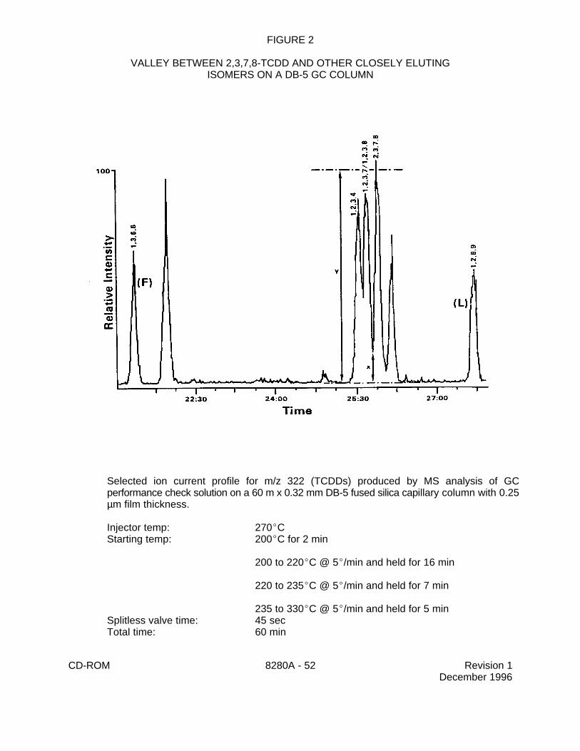
On the DB-5 column,the chromatographic resolution is evaluated using the CC3 calibrationstandard during both the initial calibration and the calibration verification. Thechromatographic peak separation between the C -2,3,7,8-TCDD peak and the C -1,2,3,4-13 13
12 12
TCDD peak must be resolved with a valley of # 25 percent, where:
y = the peak height of any TCDD isomerx = measured as shown in Figure 2
The resolution criteria must be evaluated using measurements made on the selected ioncurrent profile (SICP) for the appropriate ions for each isomer. Measurements are not madefrom total ion current profiles.
Optimize the operating conditions for sensitivity and resolution, and employ the sameconditions for both calibration and sample analyses.
7.12.2 When an SP-2331 (or equivalent) GC column is used to confirm the results for2,3,7,8-TCDF, the chromatographic resolution is evaluated before the analysis of anycalibration standards by the analysis of a commercially-available column performance mixture(Sec. 5.16) that contains the TCDD isomers that elute most closely with 2,3,7,8-TCDD on thisGC column (1,4,7,8-TCDD and the 1,2,3,7/1,2,3,8-TCDD pair). Analyze a 2-µL aliquot of thissolution, using the column operating conditions and descriptor switching times previouslyestablished. The GC operating conditions for this column should be modified from those forthe DB-5 (or equivalent) column, focusing on resolution of the closely-eluting TCDD and TCDFisomers.
NOTE: The column performance mixture may be combined with the window definingmix into a single analysis, provided that the combined solution contains theisomers needed to determine that criteria for both analyses can be met.
Valley ' ( xy
) × 100
CD-ROM 8280A - 21 Revision 1December 1996
The chromatographic peak separation between unlabeled 2,3,7,8-TCDD and the peaksrepresenting all other unlabeled TCDD isomers should be resolved with a valley of # 25percent, where:
y = the peak height of any TCDD isomerx = measured as shown in Figure 2
The resolution criteria must be evaluated using measurements made on the selected ioncurrent profile (SICP) for the appropriate ions for each isomer. Measurements are not madefrom total ion current profiles.
Further analyses may not proceed until the GC resolution criteria have been met.
7.13 GC/MS Calibration
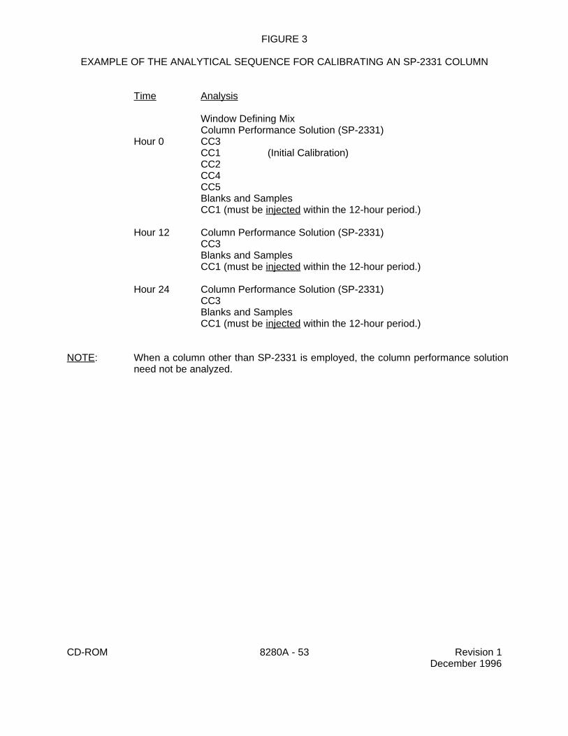
Calibration of the GC/MS system involves three separate procedures, mass calibration of theMS, establishment of GC retention time windows, and calibration of the target analytes. These threeprocedures are described in Secs. 7.13.1 to 7.13.3. Samples should not be analyzed untilacceptable descriptor switching times, chromatographic resolution, and calibrations are achievedand documented. The sequence of analyses is shown in Figure 3.
NOTE: The injection volume for all sample extracts, blanks, quality control samples andcalibration solutions must be the same.
7.13.1 Mass calibration - Mass calibration of the MS is recommended prior to analyzingthe calibration solutions, blanks, samples and QC samples. It is recommended that theinstrument be tuned to greater sensitivity in the high mass range in order to achieve betterresponse for the later eluting compounds. Optimum results using FC-43 for mass calibrationmay be achieved by scanning from 222-510 amu every 1 second or less, utilizing 70 volts(nominal) electron energy in the electron ionization mode. Under these conditions, m/z 414and m/z 502 should be 30-50% of m/z 264 (base peak).
7.13.2 Retention time windows - Prior to the calibration of the target analytes, it isnecessary to establish the appropriate switching times for the SIM descriptors (Table 7). Theswitching times are determined by the analysis of the Window Defining Mix, containing the firstand last eluting isomers in each homologue (Table 8). Mixes are available for variouscolumns.
The ions in each of the four recommended descriptors are arranged so that there isoverlap between the descriptors. The ions for the TCDD, TCDF, PeCDD, and PeCDF isomersare in the first descriptor, the ions for the PeCDD, PeCDF, HxCDD and HxCDF isomers are inthe second descriptor, the ions for the HxCDD, HxCDF, HpCDD and HpCDF isomers are in thethird, and the ions for the HpCDD, HpCDF, OCDD and OCDF isomers are in the fourthdescriptor. The descriptor switching times are set such that the isomers that elute from theGC during a given retention time window will also be those isomers for which the ions aremonitored. For the homologues that overlap between descriptors, the laboratory may usediscretion in setting the switching times. However, do not set descriptor switching times suchthat a change in descriptors occurs at or near the expected retention time of any of the 2,3,7,8-substituted isomers.
RFn '(An
1 % An2) × Q is
(Ais1 % A 2
is) × Qn
RF is '(Ais
1 % Ais2) × Q rs
(Ars1 % A 2
rs) × Q is
CD-ROM 8280A - 22 Revision 1December 1996
7.13.3 Calibration of target analytes - Two types of calibration procedures, initialcalibration and calibration verification, are necessary (Secs. 7.13.3.1 and 7.13.3.2). The initialcalibration is needed before any samples are analyzed for PCDDs/PCDFs, and intermittentlythroughout sample analysis, as dictated by the results of the calibration verification. Thecalibration verification is necessary at the beginning of each 12-hour time period during whichsample are analyzed.
7.13.3.1 Initial Calibration - Once the Window Defining Mix has been analyzedand the descriptor switching times have been verified (and after the analysis of thecolumn performance solution, if using a GC column other than DB-5), analyze the fiveconcentration calibration solutions (CC1-CC5), described in Table 1, prior to any sampleanalysis.
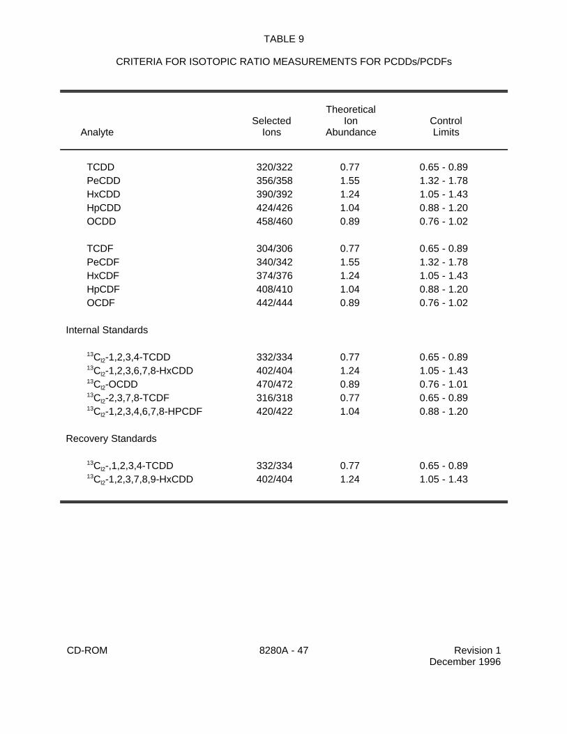
7.13.3.1.1 The relative ion abundance criteria for PCDDs/PCDFspresented in Table 9 should be met for all PCDD/PCDF peaks, including thelabeled internal and recovery standards, in all solutions. The lower and upperlimits of the ion abundance ratios represent a ±15% window around thetheoretical abundance ratio for each pair of selected ions. The Cl -2,3,7,8-37
4
TCDD cleanup standard contains no Cl, thus the ion abundance ratio criterion35
does not apply to this compound.
7.13.3.1.2 If the laboratory uses a GC column other than thosedescribed here, the laboratory must ensure that the isomers eluting closest to2,3,7,8-TCDD on that column are used to evaluate GC column resolution
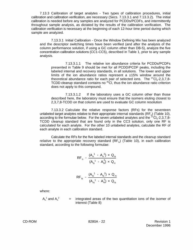
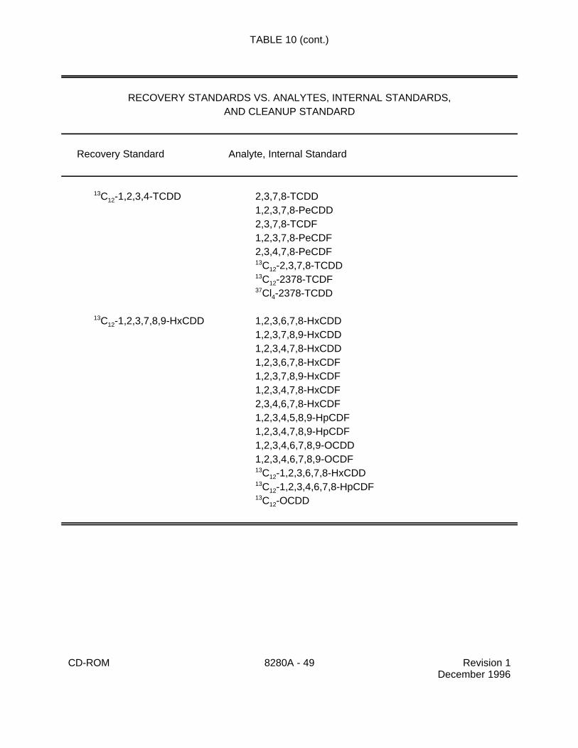
7.13.3.2 Calculate the relative response factors (RFs) for the seventeenunlabeled target analytes relative to their appropriate internal standards (RF ) (Table 10),n
according to the formulae below. For the seven unlabeled analytes and the Cl -2,3,7,8-374
TCDD cleanup standard that are found only in the CC3 solution, only one RF iscalculated for each analyte. For the other 10 unlabeled analytes, calculate the RF ofeach analyte in each calibration standard.
Calculate the RFs for the five labeled internal standards and the cleanup standardrelative to the appropriate recovery standard (RF ) (Table 10), in each calibrationis
standard, according to the following formulae:
where:
A and A = integrated areas of the two quantitation ions of the isomer ofn n1 2
interest (Table 8)
RFrs ' RFn × RFis
%RSD 'Standard deviation
Mean RF× 100
CD-ROM 8280A - 23 Revision 1December 1996
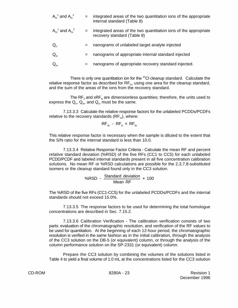
A and A = integrated areas of the two quantitation ions of the appropriateis is1 2
internal standard (Table 8)
A and A = integrated areas of the two quantitation ions of the appropriaters rs1 2
recovery standard (Table 8)
Q = nanograms of unlabeled target analyte injectedn
Q = nanograms of appropriate internal standard injectedis
Q = nanograms of appropriate recovery standard injected.rs
There is only one quantitation ion for the Cl cleanup standard. Calculate the37
relative response factor as described for RF , using one area for the cleanup standard,is
and the sum of the areas of the ions from the recovery standard.
The RF and xRF are dimensionless quantities; therefore, the units used ton is
express the Q , Q , and Q must be the same.n is rs
7.13.3.3 Calculate the relative response factors for the unlabeled PCDDs/PCDFsrelative to the recovery standards (RF ), where:rs
This relative response factor is necessary when the sample is diluted to the extent thatthe S/N ratio for the internal standard is less than 10.0.
7.13.3.4 Relative Response Factor Criteria - Calculate the mean RF and percentrelative standard deviation (%RSD) of the five RFs (CC1 to CC5) for each unlabeledPCDD/PCDF and labeled internal standards present in all five concentration calibrationsolutions. No mean RF or %RSD calculations are possible for the 2,3,7,8-substitutedisomers or the cleanup standard found only in the CC3 solution.
The %RSD of the five RFs (CC1-CC5) for the unlabeled PCDDs/PCDFs and the internalstandards should not exceed 15.0%.
7.13.3.5 The response factors to be used for determining the total homologueconcentrations are described in Sec. 7.15.2.
7.13.3.6 Calibration Verification - The calibration verification consists of twoparts: evaluation of the chromatographic resolution, and verification of the RF values tobe used for quantitation. At the beginning of each 12-hour period, the chromatographicresolution is verified in the same fashion as in the initial calibration, through the analysisof the CC3 solution on the DB-5 (or equivalent) column, or through the analysis of thecolumn performance solution on the SP-2331 (or equivalent) column.
Prepare the CC3 solution by combining the volumes of the solutions listed inTable 4 to yield a final volume of 1.0 mL at the concentrations listed for the CC3 solution
% Difference '(RFi & RFc)
RFi
× 100
CD-ROM 8280A - 24 Revision 1December 1996
in Table 1. Alternatively, use a commercially-prepared solution that contains the targetanalytes at the CC3 concentrations listed in Table 1.
For the DB-5 (or equivalent) column, begin the 12-hour period by analyzing theCC3 solution. Inject a 2-µL aliquot of the calibration verification solution (CC3) into theGC/MS. The identical GC/MS/DS conditions used for the analysis of the initial calibrationsolutions must be used for the calibration verification solution. Evaluate thechromatographic resolution using the QC criteria in Sec. 7.12.1.
For the SP-2331 (or equivalent) column, or other columns with different elutionorders, begin the 12-hour period with the analysis of a 2-µL aliquot of the appropriatecolumn performance solution. Evaluate the chromatographic resolution using the QCcriteria in Sec. 7.12.2. If this solution meets the QC criteria, proceed with the analysisof a 2-µL aliquot of the CC3 solution. The identical GC/MS/DS conditions used for theanalysis of the initial calibration solutions must be used for the calibration verificationsolution.
Calculate the RFs for the seventeen unlabeled target analytes relative to theirappropriate internal standards (RF ) and the response factors for the five labeled internaln
standards and the cleanup standard relative to the appropriate recovery standard (RF ),is
according to the formulae in Sec. 7.13.3.2.
Calculate the RFs for the unlabeled PCDDs/PCDFs relative to the recoverystandards (RF ), using the formula in Sec. 7.13.3.3.rs
Do not proceed with sample analyses until the calibration verification criteria havebeen met for:
1) GC Column Resolution Criteria - The chromatographic resolution on the DB-5(or equivalent) and /or the SP-2331 (or equivalent) column must meet the QC criteria inSec. 7.12. In addition, the chromatographic peak separation between the 1,2,3,4,7,8-HxCDD and the 1,2,3,6,7,8-HxCDD in the CC3 solution shall be resolved with a valleyof # 50 percent (Figure 2).
2) Ion Abundance Criteria - The relative ion abundances listed in Table 9 mustbe met for all PCDD/PCDF peaks, including the labeled internal and recovery standards.
3) Instrument Sensitivity Criteria - For the CC3 solution, the signal-to-noise (S/N)ratio shall be greater than 2.5 for the unlabeled PCDD/PCDF ions, and greater than 10.0for the labeled internal and recovery standards.
4) Response Factor Criteria - The measured RFs of each analyte and internalstandard in the CC3 solution must be within ±30.0% of the mean RFs established duringinitial calibration for the analytes in all five calibration standards, and within ±30.0% of thesingle-point RFs established during initial calibration for those analytes present in onlythe CC3 standard (see Sec. 7.13.3.2).
where:
CD-ROM 8280A - 25 Revision 1December 1996
RF = Relative response factor established during initial calibration.i
RF = Relative response factor established during calibration verification.c
7.13.3.7 In order to demonstrate that the GC/MS system has retained adequatesensitivity during the course of sample analyses, the lowest standard from the initialcalibration is analyzed at the end of each 12-hour time period during which samples areanalyzed. This analysis must utilize the same injection volume and instrument operatingconditions as were used for the preceding sample analyses.
The results of this analysis must meet the acceptance criteria for retention times,ion abundances, and S/N ratio that are listed in Sec 7.13.3.6 for the continuing calibrationstandard. Response factors do not need to be evaluated in this end-of-shift standard.If this analysis fails either the ion abundance or S/N ratio criteria, then any samplesanalyzed during that 12-hour period that indicated the presence of any PCDDs/PCDFsbelow the method quantitation limit or where estimated maximum possibleconcentrations were reported must be reanalyzed. Samples with positive results abovethe method quantitation limit need not be reanalyzed.
7.14 GC/MS analysis of samples
7.14.1 Remove the extract of the sample or blank from storage. Gently swirl the solventon the lower portion of the vial to ensure complete dissolution of the PCDDs/PCDFs.
7.14.2 Transfer a 50-µL aliquot of the extract to a 0.3-mL vial, and add sufficientrecovery standard solution to yield a concentration of 0.5 ng/µL. Reduce the volume of theextract back down to 50 µL using a gentle stream of dry nitrogen.
7.14.3 Inject a 2-µL aliquot of the extract into the GC/MS instrument. Reseal the vialcontaining the original concentrated extract. Analyze the extract by GC/MS, and monitor allof the ions listed in Table 7. The same MS parameters used to analyze the calibrationsolutions must be used for the sample extracts.
7.14.4 Dilution of the sample extract is necessary if the concentration of anyPCDD/PCDF in the sample has exceeded the calibration range, or the detector has beensaturated. An appropriate dilution will result in the largest peak in the diluted sample fallingbetween the mid-point and high-point of the calibration range.
7.14.4.1 Dilutions are performed using an aliquot of the original extract, of whichapproximately 50 µL remain from Sec. 7.14.2. Remove an appropriate size aliquot fromthe vial and add it to a sufficient volume of tridecane (or nonane) in a clean 0.3-mLconical vial. Add sufficient recovery standard solution to yield a concentration of 0.5ng/µL. Reduce the volume of the extract back down to 50 µL using a gentle stream ofdry nitrogen.
7.14.4.2 The dilution factor is defined as the total volume of the sample aliquotand clean solvent divided by the volume of the sample aliquot that was diluted.
7.14.4.3 Inject 2 µL of the diluted sample extract into the GC/MS, and analyzeaccording to Secs. 7.14.1 through 7.14.3.
RRT 'retention time of the analyte
retention time of the corresponding internal standard
CD-ROM 8280A - 26 Revision 1December 1996
7.14.4.4 Diluted samples in which the MS response of any internal standard isgreater than or equal to 10% of the MS response of that internal standard in the mostrecent calibration verification standard are quantitated using the internal standards.
Diluted samples in which the MS response of any internal standard is lessthan 10% of the MS response of that internal standard in the most recentcalibration verification standard are quantitated using the recovery standards (seeSec. 7.15.3).
7.14.5 Identification Criteria - For a gas chromatographic peak to be unambiguously
identified as a PCDD or PCDF, it must meet all of the following criteria.
7.14.5.1 Retention times - In order to make a positive identification of the 2,3,7,8-substituted isomers for which an isotopically labeled internal or recovery standard ispresent in the sample extract, the absolute retention time (RT) at the maximum peakheight of the analyte must be within -1 to +3 seconds of the retention time of thecorresponding labeled standard.
In order to make a positive identification of the 2,3,7,8-substituted isomers forwhich a labeled standard is not available, the relative retention time (RRT) of the analytemust be within 0.05 RRT units of the RRT established by the calibration verification. TheRRT is calculated as follows:
For non-2,3,7,8-substituted compounds (tetra through hepta), the retention timemust be within the retention time windows established by the window defining mix for thecorresponding homologue (Sec. 7.13.2).
In order to assure that retention time shifts do not adversely affect theidentification of PCDDs/PCDFs, the absolute retention times of the two recoverystandards added to every sample extract immediately prior to analysis may not shift bymore than ±10 seconds from their retention times in the calibration verification standard.
7.14.5.2 Peak identification - All of the ions listed in Table 8 for eachPCDD/PCDF homologue and labeled standards must be present in the SICP. The ioncurrent response for the two quantitation ions and the M-[COCL] ions for the analytes+
must maximize simultaneously (±2 seconds). This requirement also applies to theinternal standards and recovery standards. For the cleanup standard, only one ion ismonitored.
7.14.5.3 Signal-to-noise ratio - The integrated ion current for each analyte ionlisted in Table 8 must be at least 2.5 times background noise and must not havesaturated the detector (Figure 4). The internal standard ions must be at least 10.0 timesbackground noise and must not have saturated the detector. However, if the M-[COCL]+
ion does not meet the 2.5 times S/N requirement but meets all the other criteria listed inSec. 7.14.5 and, in the judgement of the GC/MS Interpretation Specialist the peak is aPCDD/PCDF, the peak may be reported as positive and the data flagged on the reportform.
Cn (µg/kg) 'Qis × (A 1
n % A 2n )
W × (A 1is % A 2
is) × RFn
Cn (ng/L) 'Qis × (A 1
n % A 2n )
V × (A 1is % A 2
is) × RFn
CD-ROM 8280A - 27 Revision 1December 1996
7.14.5.4 Ion abundance ratios - The relative ion abundance criteria listed in Table9 for unlabeled analytes and internal standards must be met using peak areas tocalculate ratios.
7.14.5.4.1 If interferences are present, and ion abundance ratios arenot met using peak areas, but all other qualitative identification criteria are met(RT, S/N, presence of all 3 ions), then use peak heights to evaluate the ion ratio.
7.14.5.4.2 If, in the judgement of the analyst, the peak is aPCDD/PCDF, then report the ion abundance ratios determined using peakheights, quantitate the peaks using peak heights rather than areas for both thetarget analyte and the internal standard, and flag the result on the report form.
The identification of a GC peak as a PCDF cannot be made if a signal having S/Ngreater than 2.5 is detected at the same retention time (±2 seconds) in the correspondingPCDPE channel (Table 8). If a PCDPE is detected, an Estimated Maximum PossibleConcentration (EMPC) should be calculated for this GC peak according to Sec. 7.15.7,regardless of the ion abundance ratio, and reported.
7.14.6 When peaks are present that do not meet all of the identification criteria in Sec.7.14.5 and the reporting of an estimated maximum possible concentration according to Sec.7.15.7 will not meet the specific project objectives, then the analyst may need to take additionalsteps to resolve the potential interference problems. However, this decision generally isproject-specific and should not be applied without knowledge of the intended application of theresults. These steps may be most appropriate when historical data indicate that 2,3,7,8-substituted PCDDs/PCDFs have been detected in samples from the site or facility, yet theresults from a specific analysis are inconclusive. The additional steps may include the use ofadditional or repeated sample cleanup procedures or the use of HRGC/MS/MS (e.g., tandemmass spectrometry).
7.15 Calculations
7.15.1 For GC peaks that have met all the identification criteria outlined in Sec. 7.14.5,calculate the concentration of the individual PCDD or PCDF isomers using the formulae:
ALL MATRICES OTHER THAN WATER:
WATER:
where:
CD-ROM 8280A - 28 Revision 1December 1996
A and A = integrated ion abundances (peak areas) of the quantitation ions of then n1 2
isomer of interest (Table 8).
A and A = integrated ion abundances (peak areas) of the quantitation ions of theis is1 2
appropriate internal standard (Table 8).
C = concentration of unlabeled PCDD/PCDF found in the sample.n
W = weight of sample extracted, in grams.
V = volume of sample extracted, in liters.
Q = nanograms of the appropriate internal standard added to the sampleis
prior to extraction.
RF = calculated relative response factor from calibration verification (seen
Sec. 7.13.3.6).
NOTE: In instances where peak heights are used to evaluate ion abundance ratiosdue to interferences (Sec. 7.14.5.4), substitute peak heights for areas in theformulae above.
For solid matrices, the units of ng/g that result from the formula above are equivalent toµg/kg. Using isotope dilution techniques for quantitation the concentration data are recoverycorrected, and therefore, the volume of the final extract and the injection volume are implicitin the value of Q .is
7.15.1.1 For homologues that contain only one 2,3,7,8-substituted isomer(TCDD, PeCDD, HpCDD, and TCDF), the RF of the 2,3,7,8-substituted isomer from thecalibration verification will be used to quantitate both the 2,3,7,8-substituted isomers andthe non-2,3,7,8-isomers.
7.15.1.2 For homologues that contain more than one 2,3,7,8-substituted isomer(HxCDD, PeCDF, HxCDF, and HpCDF), the RF used to calculate the concentration ofeach 2,3,7,8-substituted isomers will be the RF determined for that isomer during thecalibration verification.
7.15.1.3 For homologues that contain one or more non-2,3,7,8-substitutedisomer, the RF used to calculate the concentration of these isomers will be the lowestof the RFs determined during the calibration verification for the 2,3,7,8-substitutedisomers in that homologue. This RF will yield the highest possible concentration for thenon-2,3,7,8-substituted isomers.
NOTE: The relative response factors of given isomers within any homologuemay be different. However, for the purposes of these calculations, itwill be assumed that every non-2,3,7,8-substituted isomer for a givenhomologue has the same relative response factor. In order to minimizethe effect of this assumption on risk assessment, the 2,3,7,8-substituted isomer with the lowest RF was chosen as representative ofeach homologue. All relative response factor calculations for the non-2,3,7,8--substituted isomers in a given homologue are based on thatisomer.
Cn (µg/kg) 'Qrs × (A 1
n % A 2n ) × D
W × (A 1rs % A 2
rs) × RFrs
Cn (ng/L) 'Qrs × (A 1
n % A 2n ) × D
V × (A 1rs % A 2
rs) × RFrs
Ris(%) '(A 1
is % A 2is) × Qrs
(A 1rs % A 2
rs) × RFis × Qis
× 100
CD-ROM 8280A - 29 Revision 1December 1996
7.15.2 In addition to the concentrations of specific isomers, the total homologueconcentrations are also reported. Calculate the total concentration of each homologue ofPCDDs/PCDFs as follows:
Total concentration = sum of the concentrations of every positively identified isomerof each PCDD/PCDF homologue.
The total must include the non-2,3,7,8-substituted isomers as well as the 2,3,7,8-substituted isomers that are also reported separately. The total number of GC peaks includedin the total homologue concentration should be reported.
7.15.3 If the area of any internal standard in a diluted sample is less than 10% of thearea of that internal standard in the calibration verification standard, then the unlabeledPCDD/PCDF concentrations in the sample shall be estimated using the recovery standard,using the formulae that follow. The purpose is to ensure that there is an adequate MSresponse for quantitation in a diluted sample. While use of a smaller aliquot of the samplemight require smaller dilutions and therefore yield a larger area for the internal standard in thediluted extract, this practice leads to other concerns about the homogeneity of the sample andthe representativeness of the aliquot taken for extraction.
ALL MATRICES OTHER THAN WATER:
WATER:
where:
D = the dilution factor (Sec. 7.14.4.2).
A , A , A , A , Q , RF , W, and V are defined in Secs. 7.13.3.2 and 7.15.1.n n rs rs rs rs1 2 1 2
7.15.4 Report results for soil/sediment, fly ash, and chemical waste samples inmicrograms per kilogram (µg/kg) and water samples in nanograms per liter (ng/L).
7.15.5 Calculate the percent recovery, R , for each internal standard and the cleanupis
standard in the sample extract, using the formula:
where:
A , A , A , A , Q , Q , and RF are defined in Secs. 7.13.3.2 and 7.15.1. is is rs rs is rs is1 2 1 2
EDL (µg/kg) '2.5 × Qis × (H 1
n % H 2n ) × D
W × (H 1is % H 2
is) × RFn
EDL (ng/L) '2.5 × Qis × (H 1
n % H 2n ) × D
V × (H 1is % H 2
is) × RFn
CD-ROM 8280A - 30 Revision 1December 1996
NOTE: When calculating the recovery of the Cl -2,3,7,8-TCDD cleanup standard,374
only one m/z is monitored for this standard; therefore, only one peak area willbe used in the numerator of this formula. Use both peak areas of the C -13
12
1,2,3,4-TCDD recovery standard in the denominator.
7.15.5.1 The C -1,2,3,4-TCDD is used to quantitate the TCDD and TCDF1312
internal standards and the cleanup standard, and the C -1,2,3,7,8,9-HxCDD is used1312
to quantitate the HxCDD, HpCDF and OCDD internal standards (Table 10).
7.15.5.2 If the original sample, prior to any dilutions, has any internal standardwith a percent recovery of less than 25% or greater than 150%, re-extraction andreanalysis of that sample is necessary.
7.15.6 Sample specific estimated detection limit - The sample specific estimateddetection limit (EDL) is the estimate made by the laboratory of the concentration of a givenanalyte required to produce a signal with a peak height of at least 2.5 times the backgroundsignal level. The estimate is specific to a particular analysis of the sample, and will be affectedby sample size, dilution, etc.
7.15.6.1 An EDL is calculated for each 2,3,7,8-substituted isomer that is notidentified, regardless of whether or not non-2,3,7,8-substituted isomers in thathomologue are present. The EDL is also calculated for 2,3,7,8-substituted isomersgiving responses for both the quantitation ions that are less than 2.5 times thebackground level.
7.15.6.2 Use the formulae below to calculate an EDL for each absent 2,3,7,8-substituted PCDD/PCDF. The background level (H ) is determined by measuring then
height of the noise at the expected retention times of both the quantitation ions of theparticular 2,3,7,8-substituted isomer.
ALL MATRICES OTHER THAN WATER:
WATER:
where:
H and H = The peak heights of the noise for both of the quantitation ions ofn n1 2
the 2,3,7,8-substituted isomer of interest
H and H = The peak heights of both the quantitation ions of the appropriateis is1 2
internal standards
EMPCn (µg/kg) 'Qis × (A 1
n % A 2n ) × D
W × (A 1is % A 2
is) × RFn
EMPCn (ng/L) 'Qis × (A 1
n % A 2n ) × D
V × (A 1is % A 2
is) × RFn
CD-ROM 8280A - 31 Revision 1December 1996
D = dilution factor (Sec. 7.14.4.2).
Q , RF , W and V are defined in Secs. 7.13.3.2 and 7.15.1.is is
7.15.6.3 If none of the isomers within a homologue are detected, then theEDL for the "total" homologue concentration is the lowest EDL for any of the 2,3,7,8-substituted isomers that were not detected. Do not add together the EDLs for thevarious isomers. If a 2,3,7,8-substituted isomer is reported in the homologue, then noEDL for the "total" is calculated.
7.15.7 Estimated maximum possible concentration - An estimated maximumpossible concentration (EMPC) is calculated for 2,3,7,8-substituted isomers that arecharacterized by a response with an S/N of at least 2.5 for both the quantitation ions, andmeet all of the identification criteria in Sec. 7.4.5 except the ion abundance ratio criteria inSec. 7.14.5.4 or when a peak representing a PCDPE has been detected (7.15.5.5). AnEMPC is a worst-case estimate of the concentration. Calculate the EMPC according to thefollowing formulae:
ALL MATRICES OTHER THAN WATER:
WATER:
where:
A and A = Areas of both the quantitation ions.x x1 2
A , A , Q , RF, D, W, and V are defined in Secs. 7.13.3.2 and 7.15.1.is is is1 2
7.15.8 Toxic equivalent concentration (TEQ) calculation - The 2,3,7,8-TCDD toxicequivalent concentration of PCDDs/PCDFs present in the sample is calculated according tothe method recommended by the Chlorinated Dioxins Workgroup (CDWG) of the EPA and theCenters for Disease Control (CDC). This method assigns a 2,3,7,8-TCDD toxicity equivalencyfactor (TEF) to each of the seventeen 2,3,7,8-substituted PCDDs/PCDFs shown in Table 11("Update of Toxicity Equivalency Factors [TEFs] for Estimating Risks Associated withExposures to Mixtures of Chlorinated Dibenzo-p-Dioxins and -Dibenzofurans [CDDs/CDFs]"March 1989 [EPA 625/3-89/016]).
7.15.8.1 The 2,3,7,8-TCDD TEQ of the PCDDs/PCDFs present in the sample iscalculated by summing the product of the concentration for each of the compounds listedin Table 11 and the TEF for each compound. The principal purpose of making thiscalculation is to provide the data user with a single value, normalized to the toxicity of2,3,7,8-TCDD, that can more readily be used in decisions related to mixtures of thesehighly toxic compounds.
CD-ROM 8280A - 32 Revision 1December 1996
7.15.8.1.1 The exclusion of homologues such as mono-, di-, tri- andthe non-2,3,7,8-substituted isomers in the higher homologues does not mean thatthey are not toxic. Their toxicity, as estimated at this time, is much less than thetoxicity of the compounds listed in Table 11. Hence, only the 2,3,7,8-substitutedisomers are included in the TEF calculations. The procedure for calculating the2,3,7,8-TCDD toxic equivalence cited above is not claimed by the CDWG to bebased on a thoroughly established scientific foundation. Rather, the procedurerepresents a "consensus recommendation on science policy."
7.15.8.1.2 When calculating the TEQ of a sample, include only those2,3,7,8-substituted isomers that were detected in the sample and met all of thequalitative identification criteria in Sec. 7.14.5. Do not include EMPC or EDLvalues in the TEQ calculation.
7.15.8.2 The TEQ of a sample is also used in this analytical procedure todetermine when second column confirmation may be necessary. The need for secondcolumn confirmation is based on the known difficulties in separating 2,3,7,8-TCDF fromother isomers. Historical problems have been associated with the separation of 2,3,7,8-TCDF from 1,2,4,9-, 1,2,7,9-, 2,3,4,6-, 2,3,4,7- and 2,3,4,8-TCDF. Because of thetoxicological concern associated with 2,3,7,8-TCDF, additional analyses may be requiredfor some samples as described below. If project-specific requirements do not includesecond column confimation or specify a different approach to confirmation, then this stepmay be omitted and the project-specific requirements take precedence.
7.15.8.2.1 If the TEQ calculated in Sec. 7.15.8.1 is greater than 0.7ppb for soil/sediment or fly ash, 7 ppb for chemical waste, or 7 ppt for anaqueous sample, and 2,3,7,8-TCDF is either detected or reported as an EMPC,then better isomer specificity may be required than can be achieved on the DB-5column. The TEQ values listed here for the various matrices are equivalent to70% of the historical "Action Level" set by the CDC for soil concentrations of2,3,7,8-TCDD at Superfund sites. As such, it provides a conservativemechanism for determining when the additional specificity provided by a secondcolumn confirmation may be required.
7.15.8.2.2 The sample extract may be reanalyzed on a 60 m SP-2330or SP-2331 GC column (or equivalent) in order to achieve better GC resolution,and therefore, better identification and quantitation of 2,3,7,8-TCDF. Othercolumns that provide better specificity for 2,3,7,8-TCDF than the DB-5 columnmay also be used.
7.15.8.2.3 Regardless of the GC column used, for a gaschromatographic peak to be identified as a 2,3,7,8-substituted PCDD/PCDFisomer during the second column confirmation, it must meet the ion abundance,signal-to-noise, and retention time criteria listed in Sec. 7.14.5.
7.15.8.2.4 The second column confirmation analysis may beoptimized for the analysis of 2,3,7,8-TCDF, and need not be used to confirm theresults for any other 2,3,7,8-substituted PCDDs/PCDFs identified during theoriginal analysis.
CD-ROM 8280A - 33 Revision 1December 1996
8.0 QUALITY CONTROL
8.1 Refer to Chapter One and Method 8000 for specific quality control (QC) procedures.Each laboratory should maintain a formal quality assurance program. The labortory should alsomaintain records to document the quality of the data generated.
8.2 Quality control procedures necessary to evaluate the GC/MS system operation includeevaluation of chromatographic resolution, retention time windows, calibration verification andchromatographic analysis of samples. Performance criteria are given in the following sections ofMethod 8280A:
8.2.1 GC resolution criteria for the DB-5 or equivalent column are given in Sec. 7.12.1.
8.2.2 GC resolution criteria for SP-2331 or equivalent column are given in Sec. 7.12.2.
8.2.3 Initial calibration criteria are given in Sec. 7.13.3.1.
8.2.4 Relative response factor criteria for the initial calibration criteria are given in Sec.7.13.3.4.
8.2.5 Calibration verification criteria are given in Sec. 7.13.3.6.
8.2.6 Ion abundance criteria are given in Secs. 7.13.3.1, 7.13.3.6, and 7.14.5.4.
8.2.7 Instrument sensitivity criteria are given in Sec. 7.13.3.6.
8.2.8 Relative response factor criteria for the calibration verification are given in Sec.7.13.3.6.
8.2.9 Identification criteria are given in Sec. 7.14.5.
8.2.10 Criteria for Isotopic Ratio Measurements for PCDDs/PCDFs are given in 7.13.3.1,7.13.3.6, and Table 9.
8.3 Initial Demonstration of Proficiency - Each laboratory must demonstrate initial proficiencywith each sample preparation and determinative method combination it utilizes, by generating dataof acceptable accuracy and precision for target analytes in a clean matrix. The laboratory must alsorepeat the following operations whenever new staff are trained or significant changes ininstrumentation are made. See Method 8000, Sec. 8.0 for information on how to accomplish thisdemonstration.
8.4 Sample Quality Control for Preparation and Analysis - The laboratory must also haveprocedures for documenting the effect of the matrix on method performance (precision, accuracy,and detection limit). At a minimum, this includes the analysis of QC samples including a methodblank, a matrix spike, a duplicate, and a laboratory control sample (LCS) in each analytical batch.
8.4.1 Documenting the effect of the matrix should include the analysis of at least onematrix spike and one duplicate unspiked sample or one matrix spike/matrix spike duplicate pair.The decision on whether to prepare and analyze duplicate samples or a matrix spike/matrixspike duplicate must be based on a knowledge of the samples in the sample batch. If samplesare expected to contain target analytes, then laboratories may use one matrix spike and aduplicate analysis of an unspiked field sample. If samples are not expected to contain target
CD-ROM 8280A - 34 Revision 1December 1996
analytes, laboratories should use a matrix spike and matrix spike duplicate pair. Consult Sec.8 of Method 8000 for information on developing acceptance criteria for the MS/MSD.
8.4.2 A Laboratory Control Sample (LCS) should be included with each analytical batch.The LCS consists of an aliquot of a clean (control) matrix similar to the sample matrix and ofthe same weight or volume. The LCS is spiked with the same analytes at the sameconcentrations as the matrix spike. When the results of the matrix spike analysis indicate apotential problem due to the sample matrix itself, the LCS results are used to verify that thelaboratory can perform the analysis in a clean matrix. Consult Sec. 8 of Method 8000 forinformation on developing acceptance criteria for the LCS.
8.4.3 The analysis of method blanks is critical to the provision of meaningful sampleresults.
8.4.3.1 Method blanks should be prepared at a frequency of at least 5%, thatis, one method blank for each group of up to 20 samples prepared at the same time, bythe same procedures.
8.4.3.2 When sample extracts are subjected to cleanup procedures, theassociated method blank must also be subjected to the same cleanup procedures.
8.4.3.4 As described in Chapter One, the results of the method blank should be:
8.4.3.4.1 Less than the MDL for the analyte.
8.4.3.4.2 Less than 5% of the regulatory limit associated with ananalyte.
8.4.3.4.3 Or less than 5% of the sample result for the same analyte,whichever is greater.
8.4.3.4.4 If the method blank results do not meet the acceptancecriteria above, then the laboratory should take corrective action to locate andreduce the source of the contamination and to re-extract and reanalyze anysamples associated with the contaminated method blank.
8.4.4 The laboratory should not subtract the results of the method blank from those ofany associated samples. Such "blank subtraction" is inappropriate and often leads to negativesample results. If the method blank results do not meet the acceptance criteria in 8.4.3 andreanalysis is not practical, then the data user should be provided with the sample results, themethod blank results, and a discussion of the corrective actions undertaken by the laboratory.
8.5 It is recommended that the laboratory adopt additional quality assurance practices for usewith this method. The specific practices that are most productive depend upon the needs of thelaboratory and the nature of the samples. Whenever possible, the laboratory should analyzestandard reference materials and participate in relevant performance evaluation studies.
9.0 METHOD PERFORMANCE
Method performance data are currently not available.
CD-ROM 8280A - 35 Revision 1December 1996
10.0 REFERENCES
1. "Update of Toxicity Equivalency Factors (TEFs) for Estimating Risks Associated withExposures to Mixtures of Chlorinated Dibenzo-p-Dioxins and Dibenzofurans (CDDs/CDFs)",March 1989 (EPA 6251/3-89/016).
2. "Method 8290: Polychlorinated Dibenzodioxins (PCDDs) and Polychlorinated Dibenzofurans(PCDFs) by High Resolution Gas Chromatography/High Resolution Mass Spectrometry(HRGC/HRMS)", Test Methods for Evaluating Solid Waste, Physical/Chemical Methods (EPAOSW SW-846).
3. "Statement of Work for Analysis of Polychlorinated Dibenzo-p-dioxins (PCDD) andPolychlorinated Dibenzofurans, Multi-Media, Multi-Concentration, DFLM01.1", September 1991.
4. Method 613: 2,3,7,8-Tetrachlorodibenzo-p-Dioxin, 40 CFR Part 136, Guidelines EstablishingTest Procedures for the Analysis of Pollutants Under the Clean Water Act, October 26, 1984.
11.0 RECOMMENDED SAFETY AND HANDLING PROCEDURES FOR PCDDs/PCDFs
11.1 The following safety practices are excerpts from EPA Method 613, Sec. 4 (July 1982version) and amended for use in conjunction with this method. The 2,3,7,8-TCDD isomer has beenfound to be acnegenic, carcinogenic, and teratogenic in laboratory animal studies. Other PCDDsand PCDFs containing chlorine atoms in positions 2,3,7,8 are known to have toxicities comparableto that of 2,3,7,8-TCDD. The analyst should note that finely divided dry soils contaminated withPCDDs and PCDFs are particularly hazardous because of the potential for inhalation and ingestion.It is recommended that such samples be processed in a confined environment, such as a hood ora glove box. Laboratory personnel handling these types of samples should wear masks fitted withcharcoal filters to prevent inhalation of dust.
11.2 The toxicity or carcinogenicity of each reagent used in this method is not preciselydefined; however, each chemical compound should be treated as a potential health hazard. Fromthis viewpoint, exposure to these chemicals must be kept to a minimum. The laboratory isresponsible for maintaining a current awareness file of OSHA regulations regarding the safe handlingof the chemicals listed in this method. A reference file of material safety data sheets should bemade available to all personnel involved in the chemical analysis of samples suspected to containPCDDs and/or PCDFs.
11.3 Each laboratory must develop a strict safety program for the handling of PCDDs andPCDFs. The laboratory practices listed below are recommended.
11.3.1 Contamination of the laboratory will be minimized by conducting most of themanipulations in a hood.
11.3.2 The effluents of sample splitters for the gas chromatograph and roughing pumpson the HRGC/HRMS system should pass through either a column of activated charcoal or bebubbled through a trap containing oil or high boiling alcohols.
11.3.3 Liquid waste should be dissolved in methanol or ethanol and irradiated withultraviolet light at a wavelength less than 290 nm for several days (use F 40 BL lamps, orequivalent). Using this analytical method, analyze the irradiated liquid wastes and dispose ofthe solutions when 2,3,7,8-TCDD and -TCDF congeners can no longer be detected.
CD-ROM 8280A - 36 Revision 1December 1996
11.4 The following precautions were issued by Dow Chemical U.S.A. for safe handling of2,3,7,8-TCDD in the laboratory and amended for use in conjunction with this method. The followingstatements on safe handling are as complete as possible on the basis of available toxicologicalinformation. The precautions for safe handling and use are necessarily general in nature sincedetailed, specific recommendations can be made only for the particular exposure and circumstancesof each individual use. Assistance in evaluating the health hazards of particular plant conditions maybe obtained from certain consulting laboratories and from State Departments of Health or of Labor,many of which have an industrial health service. The 2,3,7,8-TCDD isomer is extremely toxic tocertain kinds of laboratory animals. However, it has been handled for years without injury inanalytical and biological laboratories. Many techniques used in handling radioactive and infectiousmaterials are applicable to 2,3,7,8-TCDD.
11.4.1 Protective Equipment - Disposable plastic gloves, apron or lab coat, safetyglasses and laboratory hood adequate for radioactive work. However, PVC gloves should notbe used.
11.4.2 Training - Workers must be trained in the proper method of removingcontaminated gloves and clothing without contacting the exterior surfaces.
11.4.3 Personal Hygiene - Thorough washing of hands and forearms after eachmanipulation and before breaks (coffee, lunch, and shift).
11.4.4 Confinement - Isolated work area, posted with signs, segregated glassware andtools, plastic backed absorbent paper on bench tops.
11.4.5 Waste - Good technique includes minimizing contaminated waste. Plastic bagliners should be used in waste cans.
11.4.6 Disposal of Hazardous Wastes - Refer to the November 7, 1986 issue of theFederal Register on Land Ban Rulings for details concerning the handling of dioxin containingwastes.
11.4.7 Decontamination of Personnel - apply a mild soap with plenty of scrubbing action.Glassware, tools and surfaces - Chlorothene NU Solvent (Trademark of the Dow ChemicalCompany) is the least toxic solvent shown to be effective. Satisfactory cleaning may beaccomplished by rinsing with Chlorothene, then washing with a detergent and water. Dishwater may be disposed to the sewer after percolation through a charcoal bed filter. It isprudent to minimize solvent wastes because they require special disposal through commercialservices that are expensive.
11.4.8 Laundry - Clothing known to be contaminated should be disposed with theprecautions described under "Disposal of Hazardous Wastes". Laboratory coats or otherclothing worn in 2,3,7,8-TCDD work area may be laundered. Clothing should be collected inplastic bags. Persons who convey the bags and launder the clothing should be advised of thehazard and trained in proper handling. The clothing may be put into a washer without contactif the launderer knows the problem. The washer should be run through one full cycle beforebeing used again for other clothing.
11.4.9 Wipe Tests - A useful method for determining cleanliness of work surfaces andtools is to wipe the surface with a piece of filter paper, extract the filter paper and analyze theextract.
CD-ROM 8280A - 37 Revision 1December 1996
11.4.10 Inhalation - Any procedure that may generate airborne contamination mustbe carried out with good ventilation. Gross losses to a ventilation system must not be allowed.Handling of the dilute solutions normally used in analytical and animal work presents nosignificant inhalation hazards except in case of an accident.
11.4.11 Accidents - Remove contaminated clothing immediately, taking precautionsnot to contaminate skin or other articles. Wash exposed skin vigorously and repeatedly untilmedical attention is obtained.
11.5 It is recommended that personnel working in laboratories where PCDD/PCDF are handledbe given periodic physical examinations (at least annually). Such examinations should includespecialized tests, such as those for urinary porphyrins and for certain blood parameters which, basedupon published clinical observations, are appropriate for persons who may be exposed toPCDDs/PCDFs. Periodic facial photographs to document the onset of dermatologic problems arealso advisable.
CD-ROM 8280A - 38 Revision 1December 1996
TABLES IN METHOD 8280
Table 1 Calibration Solutions
Table 2 Quantitation Limits for Target Compounds
Table 3 Internal Standard, Recovery Standard, and Cleanup Standard solutions
Table 4 Calibration Verification Solution
Table 5 Matrix Spiking Solution
Table 6 PCDD/PCDF Isomers in the Window Defining Mix for a 60 m DB-5 Column
Table 7 Recommended Selected Ion Monitoring Descriptors
Table 8 Ions Specified for Selected Ion Monitoring for PCDDs/PCDFs
Table 9 Criteria for Isotopic Ratio Measurements for PCDDs/PCDFs
Table 10 Relationship of Internal Standards to Analytes, and Recovery Standards to InternalStandards, Cleanup Standard, and Analytes
Table 11 2,3,7,8-TCDD Toxicity Equivalency Factors (TEFs) for the PCDDs/PCDFs
FIGURES IN METHOD 8280
Figure 1 General Structures of PCDDs (top) and PCDFs (bottom).
Figure 2 Valley Between 2,3,7,8-TCDD and Other Closely Eluting Isomers on a DB-5 GC Column.
Figure 3 Example of the Analytical Sequence for Calibrating an SP-2331 Column.
Figure 4 Measurement of the Signal-to-noise Ratio.
* “Chemical waste” includes the matrices of oils, still bottoms, oily sludge, wet fuel oil, oil-laced soil,and surface water heavily contaminated with these matrices.
CD-ROM 8280A - 41 Revision 1December 1996
TABLE 3
INTERNAL STANDARD, RECOVERY STANDARD, AND CLEANUP STANDARD SOLUTIONS
INTERNAL STANDARD SOLUTION
Internal Standards Concentration
C -2,3,7,8-TCDD 5 ng/µL13l2
C -2,3,7,8-TCDF 5 ng/µL13l2
C -1,2,3,6,7,8-HxCDD 5 ng/µL13l2
C -1,2,3,4,6,7,8-HpCDF 10 ng/µL13l2
C -OCDD 10 ng/µL13l2
RECOVERY STANDARD SOLUTION
Recovery Standards Concentration
C -1,2,3,4-TCDD 5 ng/µL13l2
C -1,2,3,7,8,9-HxCDD 5 ng/µL13l2
CLEANUP STANDARD SOLUTION
Cleanup Standards Concentration
Cl -2,3,7,8-TCDD 5 ng/µL374
CD-ROM 8280A - 42 Revision 1December 1996
TABLE 4
CALIBRATION VERIFICATION SOLUTION
Volume Solution
500 µL CC4 (Table 1)125 µL Supplemental Calibration solution (below)50 µL Internal Standard solution (Table 3)50 µL Recovery Standard solution (Table 3)50 µL Cleanup Standard solution (Table 3)
225 µL Tridecane (or nonane)
This solution will yield a final volume of 1.0 mL at the concentrations specified for the CC3 solution inTable 1.
Supplemental Calibration Solution Prepared from Commercially-Available Materials
The ions at m/z 376 (HxCDPE), 410 (HpCDPE), 446 (OCDPE), 480 (NCDPE) and 514 (DCDPE)represent the polychlorinated diphenyl ethers.
The ions in each of the four recommended descriptors are arranged so that there is overlap betweenthe descriptors. The ions for the TCDD, TCDF, PeCDD, and PeCDF isomers are in the first descriptor,the ions for the PeCDD, PeCDF, HxCDD and HxCDF isomers are in the second descriptor, the ions forthe HxCDD, HxCDF, HpCDD and HpCDF isomers are in the third, and the ions for the HpCDD, HpCDF,OCDD and OCDF isomers are in the fourth descriptor.
CD-ROM 8280A - 46 Revision 1December 1996
TABLE 8
IONS SPECIFIED FOR SELECTED ION MONITORING FOR PCDDs/PCDFs
2,3,7,8-TCDD TOXICITY EQUIVALENCY FACTORS (TEFs) FOR THE PCDDs/PCDFs
Compound Toxicity Equivalency Factor (TEF)
Mono-, di-, and trichloro dibenzo-p-dioxins 0.0
2,3,7,8-tetrachloro-dibenzo-p-dioxin 1.0
All other tetrachloro-dibenzo-p-dioxins 0.0
1,2,3,7,8-pentachloro-dibenzo-p-dioxin 0.5
All other pentachloro-dibenzo-p-dioxins 0.0
1,2,3,4,7,8-hexachloro-dibenzo-p-dioxin 0.1
1,2,3,6,7,8-hexachloro-dibenzo-p-dioxin 0.1
1,2,3,7,8,9-hexachloro-dibenzo-p-dioxin 0.1
All other hexachloro-dibenzo-p-dioxins 0.0
1,2,3,4,6,7,8-heptachloro-dibenzo-p-dioxin 0.01
All other heptachloro-dibenzo-p-dioxins 0.0
Octachloro-dibenzo-p-dioxin 0.001
All mono-, di-, and trichloro dibenzofurans 0.0
2,3,7,8-tetrachlorodibenzofuran 0.1
All other tetrachlorodibenzofurans 0.0
1,2,3,7,8-pentachlorodibenzofuran 0.05
2,3,4,7,8-pentachlorodibenzofuran 0.5
All other pentachlorodibenzofurans 0.0
1,2,3,4,7,8-hexachlorodibenzofuran 0.1
1,2,3,6,7,8-hexachlorodibenzofuran 0.1
1,2,3,7,8,9-hexachlorodibenzofuran 0.1
2,3,4,6,7,8-hexachlorodibenzofuran 0.1
All other hexachlorodibenzofurans 0.0
1,2,3,4,6,7,8-heptachlorodibenzofuran 0.01
1,2,3,4,7,8,9-heptachlorodibenzofuran 0.01
All other heptachlorodibenzofurans 0.0
Octachlorodibenzofuran 0.001
CD-ROM 8280A - 51 Revision 1December 1996
FIGURE 1
GENERAL STRUCTURES OF PCDDs (top) AND PCDFs (bottom)
CD-ROM 8280A - 52 Revision 1December 1996
FIGURE 2
VALLEY BETWEEN 2,3,7,8-TCDD AND OTHER CLOSELY ELUTINGISOMERS ON A DB-5 GC COLUMN
Selected ion current profile for m/z 322 (TCDDs) produced by MS analysis of GCperformance check solution on a 60 m x 0.32 mm DB-5 fused silica capillary column with 0.25µm film thickness.
Injector temp: 270ECStarting temp: 200EC for 2 min
200 to 220EC @ 5E/min and held for 16 min
220 to 235EC @ 5E/min and held for 7 min
235 to 330EC @ 5E/min and held for 5 minSplitless valve time: 45 secTotal time: 60 min
CD-ROM 8280A - 53 Revision 1December 1996
FIGURE 3
EXAMPLE OF THE ANALYTICAL SEQUENCE FOR CALIBRATING AN SP-2331 COLUMN
Hour 0 CC3CC1 (Initial Calibration)CC2CC4CC5Blanks and SamplesCC1 (must be injected within the 12-hour period.)
Hour 12 Column Performance Solution (SP-2331)CC3Blanks and SamplesCC1 (must be injected within the 12-hour period.)
Hour 24 Column Performance Solution (SP-2331)CC3Blanks and SamplesCC1 (must be injected within the 12-hour period.)
NOTE: When a column other than SP-2331 is employed, the column performance solutionneed not be analyzed.
CD-ROM 8280A - 54 Revision 1December 1996
FIGURE 4
MEASUREMENT OF THE SIGNAL-TO-NOISE RATIO
Manual Determination of S/N
The peak height (S) is measured between the mean noise (lines C and D). These mean signal valuesare obtained by tracing the line between the baseline average noise extremes, E1 and E2, andbetween the apex average noise extremes, E3 and E4, at the apex of the signal.
NOTE: It is imperative that the instrument interface amplifier electronic zero offset be set highenough so that negative going baseline noise is recorded.
CD-ROM 8280A - 55 Revision 1December 1996
METHOD 8280A
THE ANALYSIS OF POLYCHLORINATED DIBENZO-p-DIOXINS AND POLYCHLORINATED DIBENZOFURANS BY HIGH RESOLUTION GAS
CHROMATOGRAPHY/LOW RESOLUTION MASS SPECTROMETRY (HRGC/LRMS)