126
Methods for Business Modeling Prof. Ing. Ivo Vondrak, CSc. Dept. of Computer Science Technical University of Ostrava [email protected] http://vondrak.cs.vsb.cz
| Date post: | 16-Dec-2015 |
| Category: |
Documents |
| Upload: | gertrude-stewart |
| View: | 221 times |
| Download: | 0 times |
Methods for Business Modeling
Prof. Ing. Ivo Vondrak, CSc.Dept. of Computer Science
Technical University of [email protected]
http://vondrak.cs.vsb.cz
References1. Mayer, R.J., Painter, M.: IDEF Family of Methods, Technical Report, Knowledge
Based Systems, Inc., College Station, TX, 19912. Booch, G., Jacobson, I., Rumbaugh, J.: The Unified Modeling Language User
Guide, Addison Wesley Longman, Inc., 19993. Schmuller, J.: Teaching Yourself UML in 24 Hours, Sams, 19994. Vondrak, I., Szturc, R., Kruzel, M.: Company Driven by Process Models, European
Concurrent Engineering Conference ECEC ’99, SCS, Erlangen-Nuremberg, Germany, pp. 188-193, 1999
5. Wil van der Aalst. Formalization and Verification of Event-driven Process Chains. Information and Software Technology, 41(10):639-650, 1999.
6. Wil van der Aalst. Workflow Verification: Finding Control-Flow Errors using Petri-net-based Techniques. In Business Process Management: Models, Techniques, and Empirical Studies, volume 1806 of Lecture Notes in Computer Science, pages 161-183. Springer-Verlag, Berlin, 2000.
7. Wil van der Aalst, Kees van Hee: Worklflow Management, Models, Methods, and Systems. MIT Press, 2002
8. Češka, M.: Petriho sítě, Akademické nakladatelství CERM Brno, 1994

Contents
Introduction Approaches to business modeling Formal methods for specification and analysis Software Tools Conclusions

About Methods for Business Modeling
Method is well-considered (sophisticated) system of doing or arranging something.
Business Process is a set of one or more linked procedures or activities which collectively realize a business objective or policy goal, normally within the context of an organizational structure defining functional roles and relationships.
Business Process Model is the representation of a business process in a form which supports automated manipulation, such as modeling or enactment. The process definition consists of a network of activities and their relationships, criteria to indicate the start and termination of the process, and information about the individual activities, such as participants, associated data, etc.
Workflow is the automation of a business process, in whole or part, during which documents, information or tasks are passed from one participant to another for action, according to a set of procedural rules.
Methods for business modeling represent systematic way how to specify and analyze business processes.Methods for business modeling represent systematic way how to specify and analyze business processes.
Source: Workflow Management Coalition

Purpose of Business Modeling Business Process Re-engineering (BPR) - methods that
support activities by which an enterprise reexamines its goals and how it achieves them, followed by a disciplined approach of business process redesign.
Enterprise Resource Planning (ERP) - an information system that integrates all manufacturing and related applications for an entire enterprise. Business modeling is the first step in the software process of the ERP implemenation.
Workflow Management (WFM) – generic software systems used for definition, management, enactment and control of business processes.
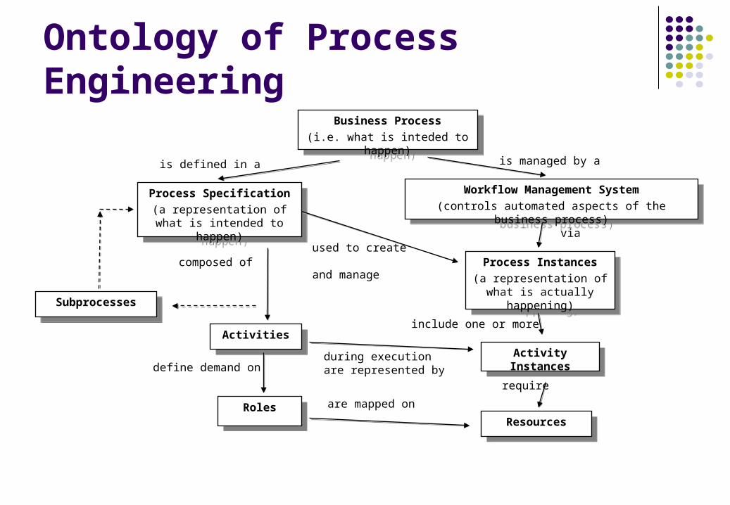
Ontology of Process Engineering
via
are mapped on
include one or more
is defined in a
during execution are represented bydefine demand on
require
used to create and manage
Business Process
(i.e. what is inteded to happen)
Business Process
(i.e. what is inteded to happen)
Process Specification
(a representation of what is intended to happen)
Process Specification
(a representation of what is intended to happen)
Workflow Management System
(controls automated aspects of the business process)
Workflow Management System
(controls automated aspects of the business process)
ActivitiesActivities
SubprocessesSubprocesses
Process Instances
(a representation of what is actually happening)
Process Instances
(a representation of what is actually happening)
RolesRoles
Activity InstancesActivity Instances
ResourcesResources
is managed by a
composed of

Approaches to Business Modeling
Abstract framework to business process specification Functional specification based on IDEF Process specification using EPC Object-oriented approach to structural modeling Using UML for business modeling Meta-model of business process
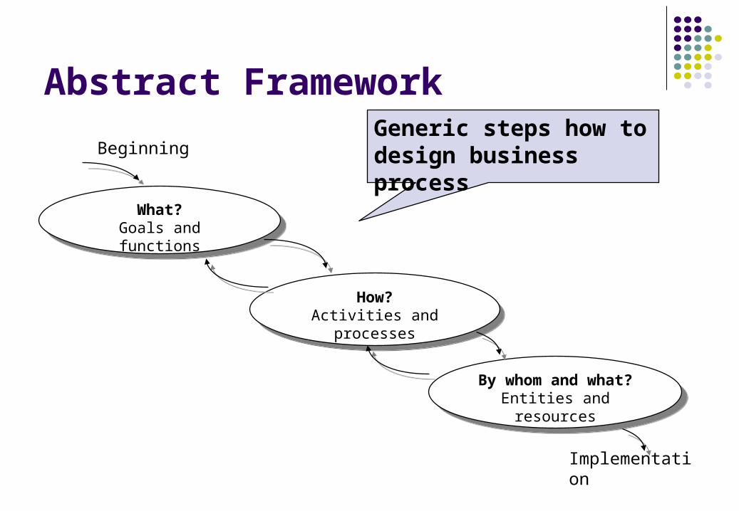
Abstract Framework
Implementation
Beginning
What?Goals and functions
What?Goals and functions
How?Activities and processes
How?Activities and processes
By whom and what?Entities and resources
By whom and what?Entities and resources
Generic steps how to design business process

Three Fundamental Abstractions Functional View. The functional view is focused on activities
as well as on entities that flow into and out of these activities. That means how the input is transformed to the required output.
Behavioral View. The behavioral view is focused on when and/or under what conditions activities are performed. The behavioral view captures the control aspect of the process model.
Structural View. The structural view is focused on the static aspect of the process. It captures objects that are manipulated and used by a process as well as the relationships that exist among them.

Consider order
Accept?
Checkavailability
Reject order
Available?
Make production plan
Purchase material
Produce articles
Ship articles
Send bill
Check payment
End
Paid?
End
Yes No
No
Yes
Yes
No
Start
Order Processing (Flow Chart)
Begining of the process
Decision block
Activity
End of the process

Integration DEFinition IDEF (Integration DEFinition language) is a software
methodology and diagramming system developed by the US Department of Defense.
IDEF is used to produce a "function model". A function model is a structured representation of the functions, activities or processes within the modeled system or subject area.
IDEF is based on SADT (Structured Analysis and Design Technique), developed by Douglas T. Ross and SofTech, Inc. In its original form, IDEF0 includes both a definition of a graphical modeling language (syntax and semantics) and a description of a comprehensive methodology for developing models.

IDEF Languages
IDEF0 is used to produce a "function model". A function model is a structured representation of the functions, activities or processes within the modeled system or subject area.
IDEF1 is used to produce information model that specifies structure and semantics of data.
IDEF2 is used to model dynamic aspects of the system, i.e. its behaviour.
IDEFx other extensions (http://www.idef.com).

Basic Concepts of IDEF0
As an analysis tool, IDEF0 assists the modeler in identifying the functions performed and what is needed to perform them.
The IDEF0 model diagram is based on a simple syntax. Each activity is described by a verb based label placed in a box. Inputs are shown as arrows entering the left side of the activity box while the outputs are shown as exiting arrows on the right side of the box. Controls are displayed as arrows entering the top of the box and mechanisms are displayed as arrows entering from the bottom of the box. Inputs, Controls, Outputs, and Mechanisms (ICOMs) are all referred to as concepts.
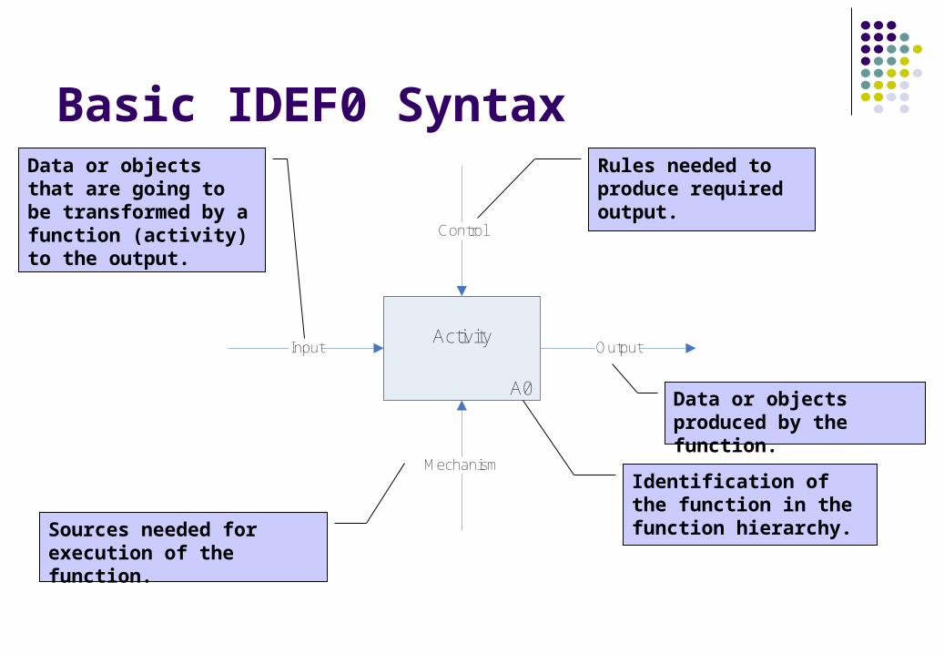
Basic IDEF0 Syntax
A0
ActivityInput Output
Control
Mechanism
Data or objects that are going to be transformed by a function (activity) to the output.
Sources needed for execution of the function.
Rules needed to produce required output.
Data or objects produced by the function.
Identification of the function in the function hierarchy.
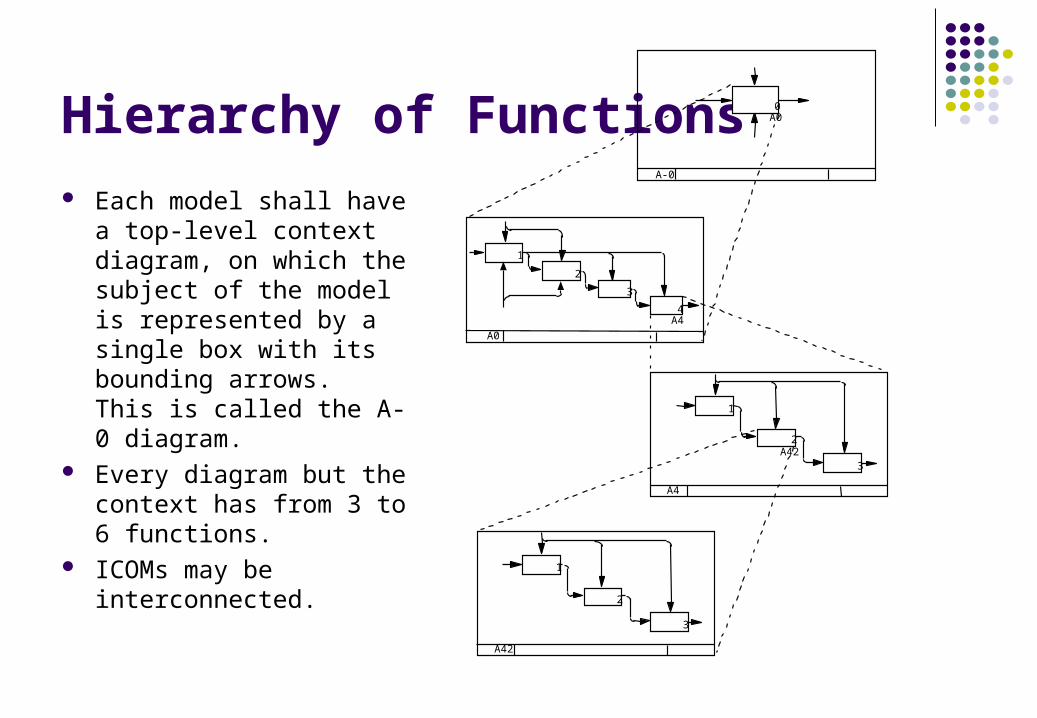
Hierarchy of Functions Each model shall have a
top-level context diagram, on which the subject of the model is represented by a single box with its bounding arrows. This is called the A-0 diagram.
Every diagram but the context has from 3 to 6 functions.
ICOMs may be interconnected.
4
3
2
1
3
3
2
1
2
1
A0
A4
A42
A-0
A4
A42
A00
A-0
A0
Order ProcessingOrder
Product assortment
Shipped articles
Sales
TITLE:NODE: NO.:A-0 Order Processing
Manufacture
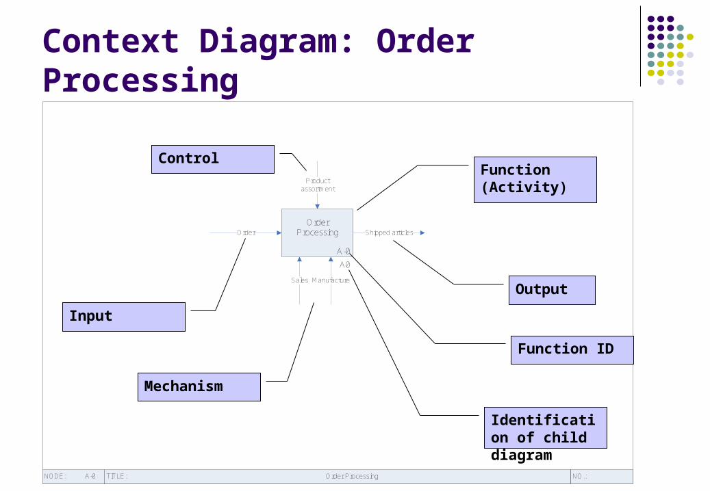
Context Diagram: Order Processing
Input
Control
Mechanism
Function (Activity)
Output
Function ID
Identification of child diagram
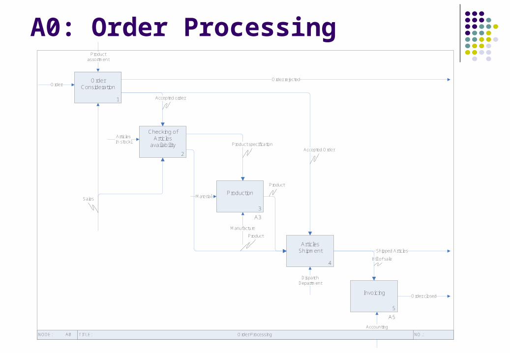
A0: Order Processing
1
Order Consideration
2
Checking of Articles
availability
3
A3
Production
4
Articles Shipment
5
A5
Invoicing
Order
Product assortment
Order rejected
Accepted order
Accepted OrderProduct specification
Material
Product
Product
ArticlesIn stockl
Shipped Articles
Bill of sale
Sales
Manufacture
Dispatch Department
Accounting Department
Order closed
TITLE:NODE: NO.:A0 Order Processing

A3: Production
TITLE:NODE: NO.:A3 Production
2
Making of Production Plan
1
Material Purchase
3
Manufacturing
Product specification
Funding
Material
Production plan
Sales
Manufacture
Product
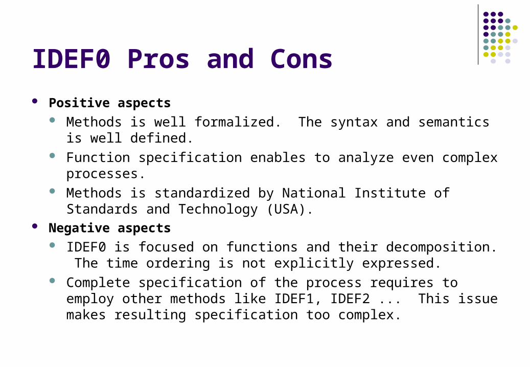
IDEF0 Pros and Cons Positive aspects
Methods is well formalized. The syntax and semantics is well defined.
Function specification enables to analyze even complex processes. Methods is standardized by National Institute of Standards and
Technology (USA). Negative aspects
IDEF0 is focused on functions and their decomposition. The time ordering is not explicitly expressed.
Complete specification of the process requires to employ other methods like IDEF1, IDEF2 ... This issue makes resulting specification too complex.

Exercise 1
Create IDEF0 diagram for function Invoicing. Assume that this function consists only from two other functions: Invoice sending and Payment checking.

Process Specification Using EPC
Event-driven Process Chains (EPC) are based on connecting events and action to the sequences which collectively realize a business objective.
Event is the precondition for the activity. New event (postcondition) is generated when the activity is finished. It means that events defines the beginning and end of each activity.
EPC diagrams are used in SAP R/3 (ERP/WFM) and ARIS (BPR).
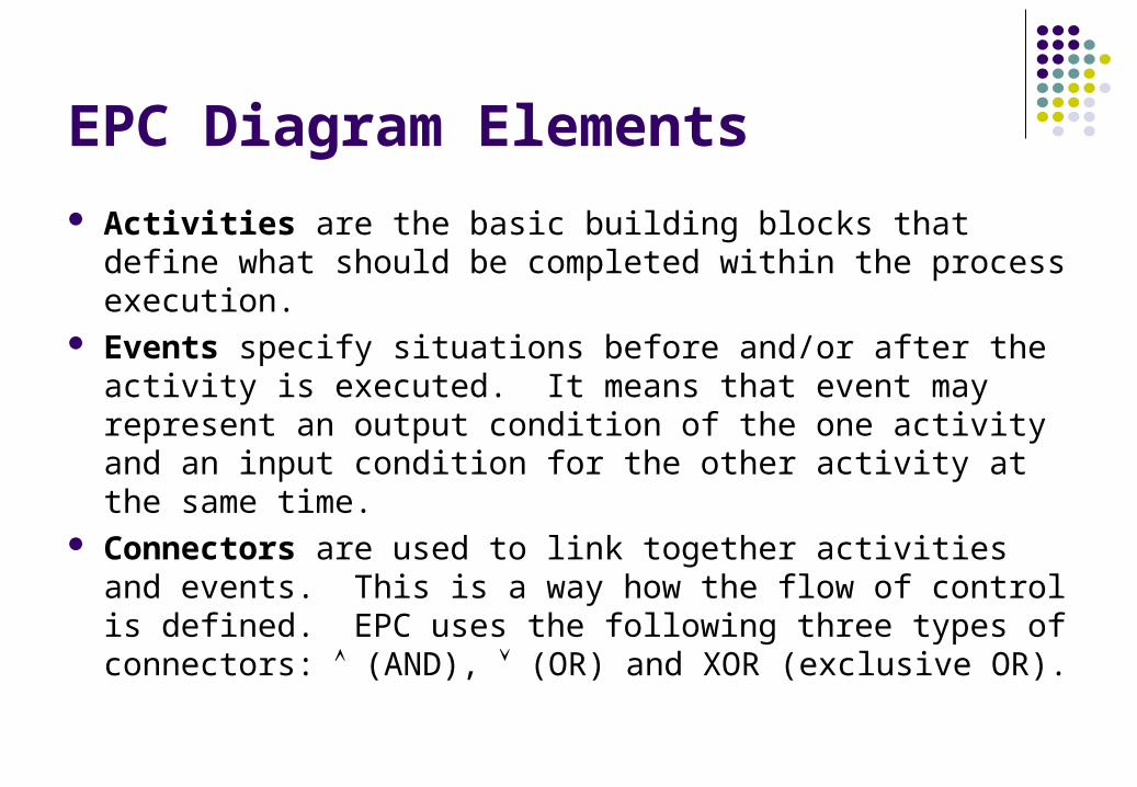
EPC Diagram Elements
Activities are the basic building blocks that define what should be completed within the process execution.
Events specify situations before and/or after the activity is executed. It means that event may represent an output condition of the one activity and an input condition for the other activity at the same time.
Connectors are used to link together activities and events. This is a way how the flow of control is defined. EPC uses the following three types of connectors: (AND), (OR) and XOR (exclusive OR).

Semantics of Connectors
AND is used either for splitting of the process to at least two concurrent process threads of execution or joining of concurrent threads to the one (synchronization point).
XOR splits the process to just one optional thread of many possible ones.
OR is used to split process to one, second or both possible threads of execution.
Orderreceived
Consider order
XOR
Orderrejected
Orderaccepted
Checkavailability
XOR
Articlesavailable
Articles mustbe produced
V
Purchase material
Make production
plan
Materialavailable
Planavailable
V
Producearticles
Articlesproduced
XOR
Ship order
Order shipped
Send bill
Outstanding accounts
XOR
Check payment
XOR
Order completed
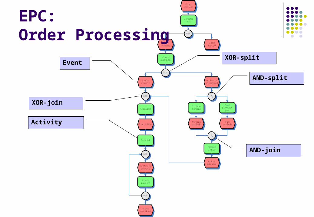
EPC: Order Processing
Event
Activity
XOR-split
XOR-join
AND-split
AND-join
Structured EPC
Complex processes have to include subrocesses – hierarchical decomposition.
Process paths represent the interface of the given process to another one (reference to another process).

Structured EPC: Order Processing
Subprocess
Process path
Orderreceived
Consider order
XOR
Orderrejected
Orderaccepted
Checkavailability
XOR
Articlesavailable
Aricles mustbe produced
Production
Articlesproduced
XOR
Ship order
Order shipped
Invoicing

Extended EPC (eEPC)
Additional information is expressed in a process model Organizational units responsible for activity execution Information sources and material ...

Orderreceived
Consider order
XOR
Orderrejected
Orderaccepted
Checkavailability
XOR
Articlesavailable
Aricles mustbe produced
Production
Articlesproduced
XOR
Ship order
Order shipped
Invoicing
Sales
Sales
Dispatch Department
Stock Database
Enterprise Resource Planning
Manufacture
eEPC: Order Processing
Organizational unit
Information
sources

EPC Pros and Cons
Positive aspects Method provides simple but powerful abstraction based on
chaining of event and activities that enables to model complex processes.
EPC is a part of widely accepted system like SAP and ARIS Negative aspects
Language for EPC diagrams is not formally defines. Syntax and semantics is not precise enough (e.g. OR has no obvious semantics assigned).
Missing formalism complicates portability of EPC between various software tools.
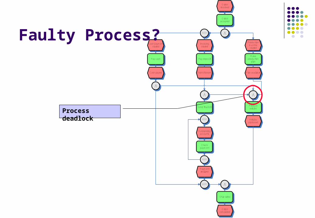
Production must be started
Make production
plan
Plan available
V
Producearticles
Articlesproduced
Orderreceived
Order accepted
V
XOR
Invoicing started
Pay deposit
Deposit payed
V
V
Send final bill
Payment realized
Ship order
Order completed
Cash payment started
Pay cash
Cash payed
XOR
XOR
Outstanding accounts
Check payment
XOR
V
Faulty Process?
Process deadlock
Exercise 2
Create Production subprocess with the respect to the following rules: All needed material has to be purchased or only some
material has to be purchased or in case that all material is in the stock no purchase is done.
Concurrently with potential material purchase the production plan is made.
Articles production can be started only in case that material and production plan are both available.
OO Approach to Structural Modeling
Object is an entity with a well-defined boundary and identity that encapsulates state and behavior.
Class is a description of a set of objects that share the same attributes, operations, methods, relationships, and semantics.
Object-oriented system architecture is the structure of connected objects that define resulting behavior of the system through their communication (interactions).

Object Model
Structural model of the business process is specified by class diagram that consists of the following elements: Classes representing active (Workers) and passive (Entities)
objects. Relationships among these classes that enable
communication among their instances (objects).
Types of Relationships Association describes a group of links with common
structure and common semantics (a Person works-for aCompany). An association a bi-directional connection between classes that describes a set of potential links in the same way that a class describes a set of potential objects.
Aggregation is the “part-whole” or “a-part-of” relationshipin which objects representing the components of somethingare associated with an object representing the entire assembly.
Generalization is the taxonomic relationship between a more general element (the parent) and a more specific element (the child) that is fully consistent with the first element and that adds additional information.

«worker»Accounting Department
-amount-due date-bank
«entity»Invoice
-article type-amount-price
«entity»Order
«entity»Article
«worker»Organizational unit
«worker»Manufacture
«worker»Dispatch Department
«worker»Sales
«worker»Company
1 *
1
*
processes
1 1
specifies
1
-product0..*
produces 1
-delivery
1..*
ships
1
*
draws1
*
checks payment
1
1
defines
Object Model: Order ProcessingClass specifying active object
Class specifying passive object
Aggregation Generalization
Association Role of object
Multiplicity

Exercise 3
Create class diagram defined by classes Sales, Manufacture, Product and Material. Describe the situation where Sales purchases Material that is required by Product to be produced. Manufacture produces the Product and uses the Material for this purpose.

Using UML for Business Modeling
The Unified Modeling Language (UML) is a standard language used to visualize, specify, construct and document the artifacts of a system.
UML uses the following three diagram for purpose of business modeling: Use case diagrams to specify functions of the system being
modeled. Activity diagrams to capture behavioral (control) aspect of
business processes. Class diagrams to specify structural properties of the system.

Functional View of the System
Use case is the specification of a sequence of actions, including variants, that a system (or other entity) can perform, interacting with actors of the system. Use case diagram shows the relationships among actors
and use cases within a system. Actor is coherent set of roles that users of use cases play
when interacting with these use cases. An actor has one role for each use case with which it communicates.
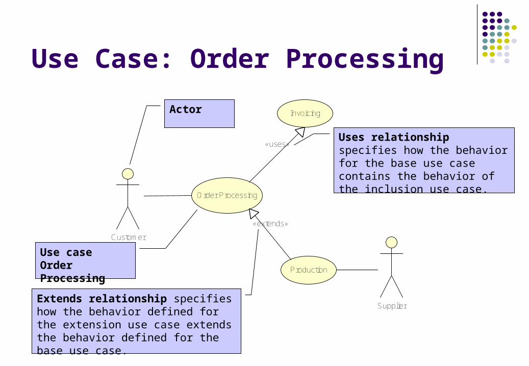
Order Processing
Customer
Production
«extends»
Invoicing
«uses»
Supplier
Use Case: Order Processing
Use case Order Processing
Actor
Uses relationship specifies how the behavior for the base use case contains the behavior of the inclusion use case.
Extends relationship specifies how the behavior defined for the extension use case extends the behavior defined for the base use case.
Control Flow
Activity Diagram is a variation of a state machine in which the states represent the performance of activities and the transitions are triggered by their completion.
The purpose of this diagram is to focus on flows driven by internal processing.
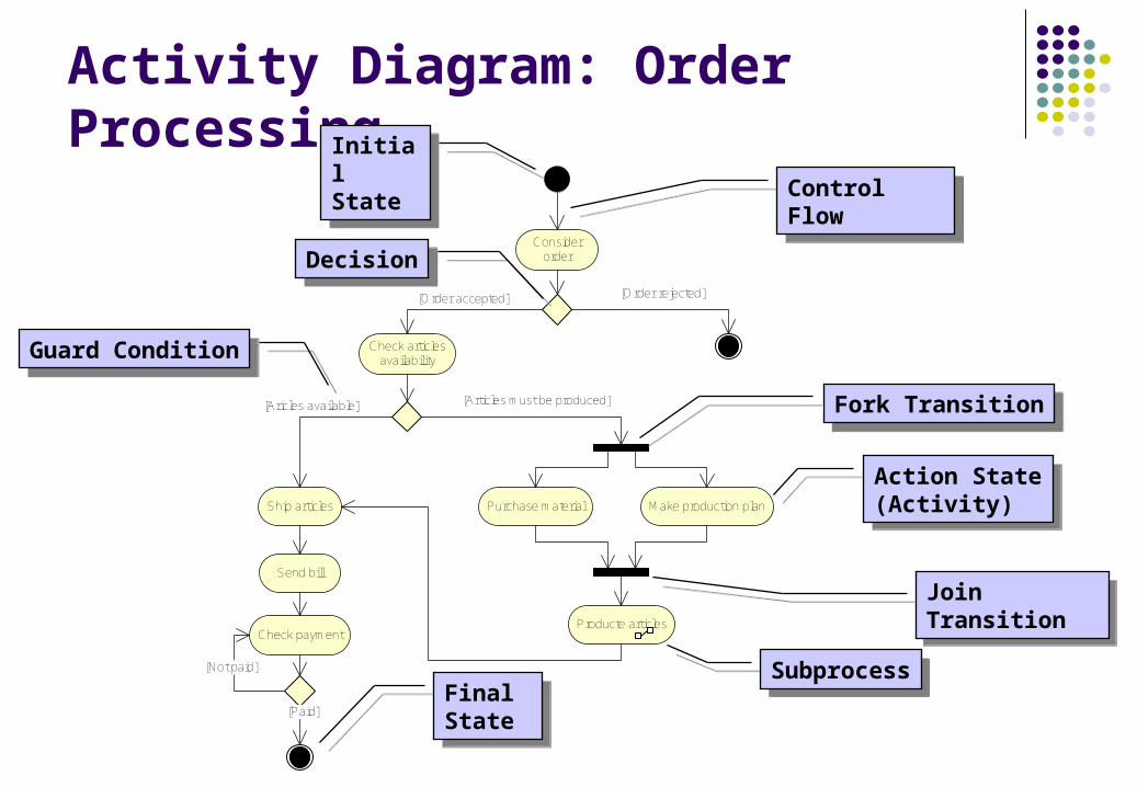
Consider order
[Order rejected]
Check articles availability
[Order accepted]
[Articles must be produced]
Purchase material Make production plan
Producte articles
Ship articles
[Aricles available]
Send bill
Check payment
[Not paid]
[Paid]
Activity Diagram: Order ProcessingInitialState
InitialState
FinalState
FinalState
Action State(Activity)
Action State(Activity)
DecisionDecision
ControlFlow
ControlFlow
Join TransitionJoin Transition
Fork TransitionFork Transition
Guard ConditionGuard Condition
SubprocessSubprocess
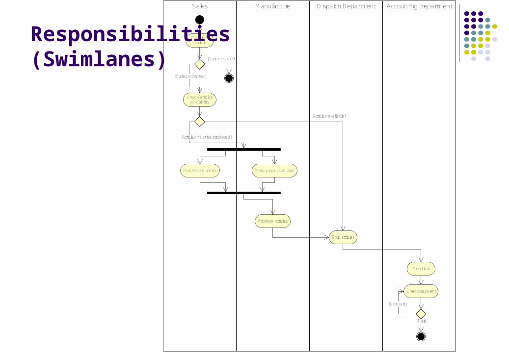
Accounting DepartmentDispatch DepartmentManufactureSales
Consider order
[Order rejected]
Check articles availability
[Order accepted]
[Articles must be produced]
Purchase material Make production plan
Produce articles
Ship articles
[Articles available]
Send bill
Check payment
[Not paid]
[Paid]
Responsibilities (Swimlanes)
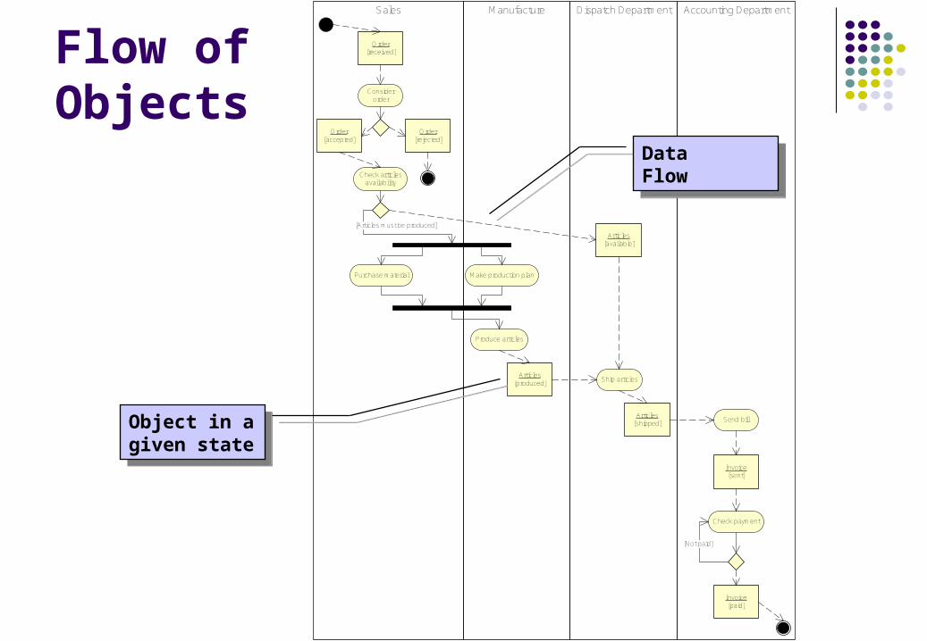
Dispatch DepartmentSales Accounting DepartmentManufacture
Consider order
Check articles availability
[Articles must be produced]
Purchase material Make production plan
Produce articles
Ship articles
Send bill
Check payment
[Not paid]
Order[received]
Order[rejected]
Order[accepted]
Articles[available]
Articles[produced]
Articles[shipped]
Invoice[sent]
Invoice[paid]
Flow of Objects
Object in a given state
Object in a given state
DataFlow
DataFlow

UML Pros and Cons Positive aspects
UML provides a large number of diagrams enabling to capture every aspects of the system being modeled.
The notation of UML is standardized and it is used by many software tools dedicated to software system design.
Since the primary focus of UML is to write software system blueprints it easy and straightforward to interconnect business modeling with the specification of information system.
Negative aspects UML is considered as a semi-formal method. The semantics
is not precisely defined. It might be a problem to verify complex processes.
Exercise 4
Define activity diagram for accounting department. Accountant issues the invoice and then he/she sends it to customer. In case that the total amount is higher than 5000 USD the invoice has to be authorized by a manager before it is sent.
Meta-Model Specification
Meta-model is a model that defines the language for expressing a model.
Business meta-model is a model for all above mentioned modeling approaches.

Business Process Meta-Model
«metaclass»Process
«metaclass»Process step
«metaclass»Activity
1
0..*
is coordinated with
«metaclass»Role
*
*
is executed by
«metaclass»Competency
*
*
specifies
«metaclass»Resource
* *
provides
«metaclass»Human
«metaclass»Machine
*
*
plays
1
*
«metaclass»Entity
«metaclass»Information
«entity»Material
«metaclass»Object
*
*
is processed within
*
*
uses
* *
is processed by
*
1
collaborates with
«metaclass»Properties
* 1
3 has
«metaclass»Goal
* 1
is realized by
1
*
is organized with
Standards in BPM Specification language BPMN (Business Process Modeling
Notation) BPMN creates a standardized bridge for the gap between the
business process design and process implementation. BPMN defines a Business Process Diagram (BPD), which is
based on a flowcharting technique tailored for creating graphical models of business process operations.
Executable Languages: BPML (Business Process Modeling Language) and BPEL (Business Process Execution Language) BPMN is supported with an internal model that enables the
generation of executable BPEL.
Formal Methods
Formal methods for specification and analysis Pi-calculus Overview Petri Nets and their properties Modeling processes by WF-Nets Analysis of business processes Fomalization and verification of informally specified processes

Formal Methods for Specification and Analysis
Formal methods include Formal specification Specification analysis and proof Transformational development Process verification
Language for formal specification has to have precise and unambiguous syntax and semantics.
Techniques for the precise and unambiguous specification of business processes.
Techniques for the precise and unambiguous specification of business processes.
Mathematical Representation of the Process
Formal specifications are expressed in a mathematical notation with precisely defined vocabulary, syntax and semantics.
Algebraic approach The system is specified in terms of its operations and their
relationships. Model-based approach
The system is specified in terms of a state model that is constructed using mathematical constructs such as sets and sequences.

Process Algebra: Pi-calculus The pi-calculus is a process algebra developed by Robin Milner. The pi-calculus is a successor of CCS (Calculus of Communicating
Systems) language. The aim of the pi-calculus is to be able to describe concurrent
computations whose configuration may change during the computation.
The pi-calculus is a mathematical formalisms for describing and analyzing properties of concurrent computation.
The pi-calculus is so minimal that it does not contain primitives such as numbers, booleans, data structures, variables, functions, or even the usual flow control statements (such as if... then...else, while...).

Names and Processes
The names are ubiquitous in the language. They roughly corresponds to identifier in programming languages, and are generally noted in lowercase (order, customer ...). Names are the only data values available in pure Pi-calcullus Some names are used to transport other names – channels
Processes represent the basic building blocks to describe behavior.
Process expressions can be arranged either sequentially (using a simple dot .) or concurrently (using verical bar |).
The Pi-calculus uses sum operator (+) to model nondeterministic choice.
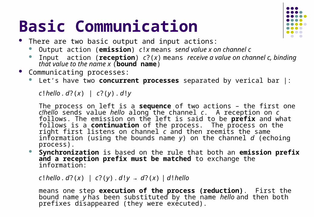
Basic Communication There are two basic output and input actions:
Output action (emission) c!x means send value x on channel c Input action (reception) c?(x) means receive a value on channel c, binding that
value to the name x (bound name) Communicating processes:
Let‘s have two concurrent processes separated by verical bar |:
c!hello . d?(x) | c?(y) . d!y
The process on left is a sequence of two actions – the first one c!hello sends value hello along the channel c. A reception on c follows. The emission on the left is said to be prefix and what follows is a continuation of the process. The process on the right first listens on channel c and then reemits the same information (using the bounds name y) on the channel d (echoing process).
Synchronization is based on the rule that both an emission prefix and a reception prefix must be matched to exchange the information:
c!hello . d?(x) | c?(y) . d!y → d?(x) | d!hello
means one step execution of the process (reduction). First the bound name y has been substituted by the name hello and then both prefixes disappeared (they were executed).
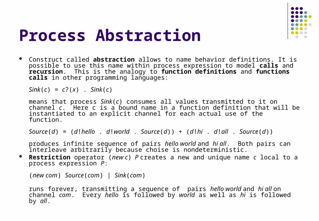
Process Abstraction Construct called abstraction allows to name behavior definitions. It is possible to use
this name within process expression to model calls and recursion. This is the analogy to function definitions and functions calls in other programming languages:
Sink(c) = c?(x) . Sink(c)
means that process Sink(c) consumes all values transmitted to it on channel c. Here c is a bound name in a function definition that will be instantiated to an explicit channel for each actual use of the function.
Source(d) = (d!hello . d!world . Source(d)) + (d!hi . d!all . Source(d))
produces infinite sequence of pairs hello world and hi all. Both pairs can interleave arbitrarily because choise is nondeterministic.
Restriction operator (new c) P creates a new and unique name c local to a process expression P:
(new com) Source(com) | Sink(com)
runs forever, transmitting a sequence of pairs hello world and hi all on channel com. Every hello is followed by world as well as hi is followed by all.
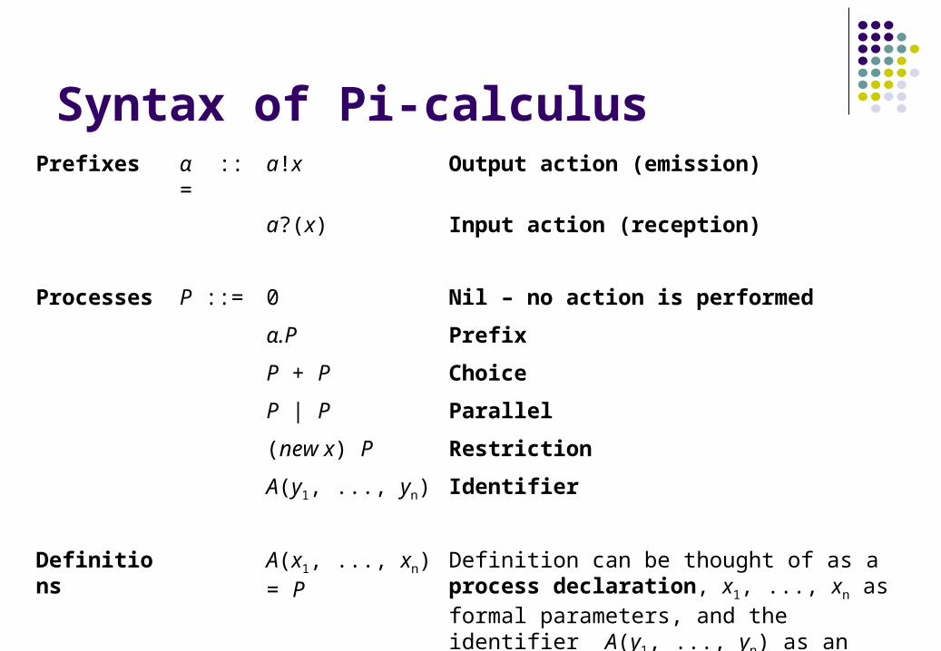
Syntax of Pi-calculusPrefixes α ::= a!x Output action (emission)
a?(x) Input action (reception)
Processes P ::= 0 Nil – no action is performed
α.P Prefix
P + P Choice
P | P Parallel
(new x) P Restriction
A(y1, ..., yn) Identifier
Definitions A(x1, ..., xn) = P Definition can be thought of as a process declaration, x1, ..., xn as formal parameters, and the identifier A(y1, ..., yn) as an invocation with actual parameters y1, ..., yn.

Example: Order Processing Definitions:
Purchase(customer,order) = customer!order . customer?(bank, bill) . bank!bill// Send order along a customer channel, wait for bank where to pay bill and pay a bill
Sale(client) = client?(specification) . client!<swissbank,invoice>// Wait for specification from client and send him/her invoice and bank connection
Execution (new steve, bmw)
Purchase(steve, bmw) | Sale(steve)
steve!bmw . steve?(bank,bill) . bank!bill | steve?(specification) . steve!<swissbank,invoice>→steve!bmw . steve?(bank,bill) . bank!bill | steve?(bmw) . steve!<swissbank,invoice>→ steve?(bank,bill) . bank!bill | steve!<swissbank,invoice>→steve?(swissbank,invoice).swissbank!invoice | steve!<swissbank,invoice>→swissbank!invoice | 0
Reconfiguration of the process (new steve, mary, bmw, honda)
Purchase(steve, bmw) | Purchase(john, honda) | Sale(steve) | Sale(mary)

Order Processing Revised Definitions:
Purchase(customer,order) = customer!order . customer?(bank,bill) . bank!bill . customer?(product)// Send order along a customer channel, wait for bank where to pay bill, pay a bill and wait for a product
Sale(client) = client?(spec) . (spec! | (bmw? . BMW(client, spec) + honda? . Honda(client,spec))// if spec = bmw then BMW(client, bmw) or if spec = honda then Honda(client, honda)
BMW(client,spec) = (production!<client,spec> . client?(car) | client!<swiss,invoice> ) . swiss?(payment) . client!car
// Produce specified car , send an invoice to the client, wait for payment and then ship a car
Honda(client,spec) = (warehouse!<client, spec> . client?(car) | client!<nomura,invoice> ) . nomura?(payment) . client!car
// Find specified car , send an invoice to the client, wait for payment and then ship a car
Production() = production?(client, specification) . (client!car | Production())// Wait for specification, start production for a client and continue waiting for a new specification
Warehouse() = warehouse?(client, specification) . (client!car | Warehouse())// Wait for a specification, start searching the car for a client and continue waiting for a new specification
Execution (new steve, bmw, mary, honda)
Purchase(steve, bmw) | Purchase(mary, honda) | Sale(steve) | Sale(mary) | Production() | Warehouse()

Finite Automata
Finite automata are defined by Q - finite set of states I - finite set of inputs : Q I Q - state transition function q0 - initial state F Q - set of final states
Visualization is based on statechart diagrams

Formal Specification of Invoice States
Q = {Articles shipped, Issued, Authorized, Not paid, Order completed}. I = {drawing, authorization, sending, payment not done, payment completed}. (Articles shipped, drawing) = Issued,
(Issued, authorization) = Authorized,(Issued, sending) = Not paid,(Authorized, sending) = Not paid,(Not paid, payment not done) = Not paid,(Not paid, payment completed) = Order completed.
q0 = Articles shipped. F = {Order completed}.

State Diagram: InvoicingInitial state q0
Initial state q0
Final stateFinal state
StateState InputInput
TransitionTransition
Articles shipped
Issued
drawing
Authorized
authorization
Not paid
sending
sending
payment completed
payment not done
Order completed

Introduction to Petri Nets
S1 S2
e
S1 S2e
Change of state modeled by Finite Automata
Change of state modeled by Petri Nets
StateState
TransitionTransition
PlacePlace TransitionTransition
Partial states modeled by Petri Nets
S11
S12
S13
e
S21
S22
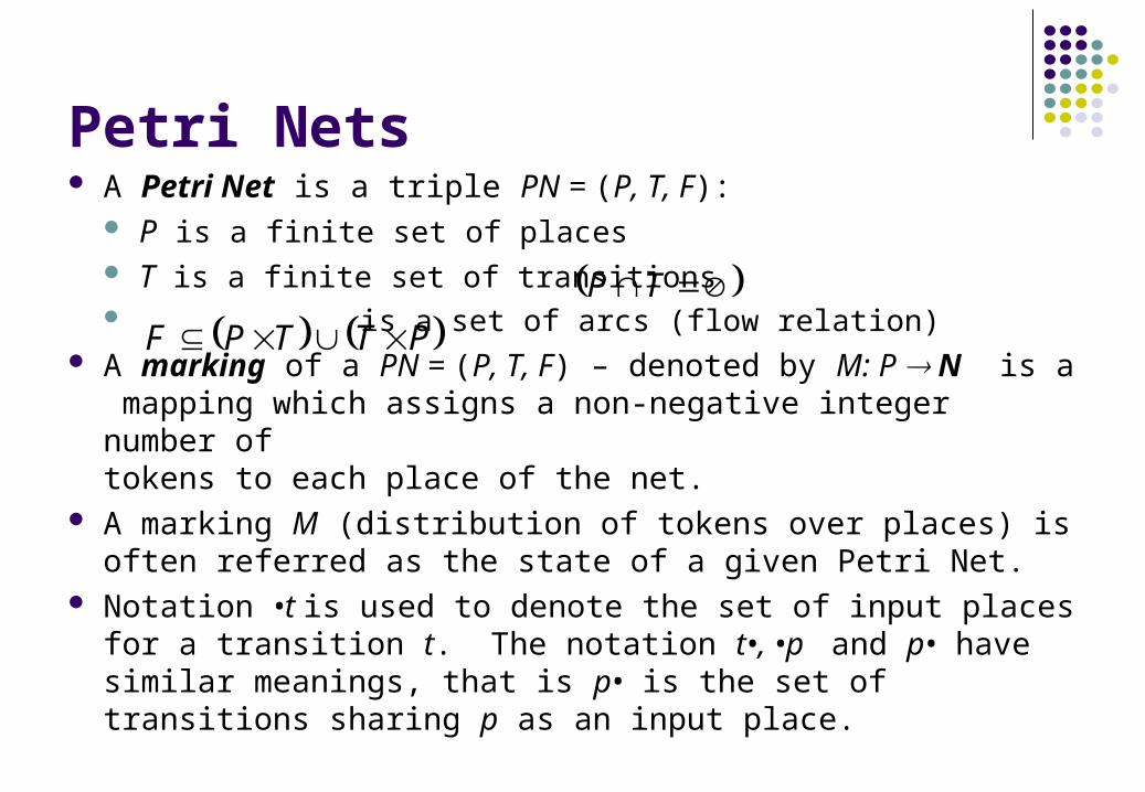
Petri Nets A Petri Net is a triple PN = (P, T, F):
P is a finite set of places T is a finite set of transitions is a set of arcs (flow relation)
A marking of a PN = (P, T, F) – denoted by M: P N is a mapping which assigns a non-negative integer number oftokens to each place of the net.
A marking M (distribution of tokens over places) is often referred as the state of a given Petri Net.
Notation •t is used to denote the set of input places for a transition t. The notation t•, •p and p• have similar meanings, that is p• is the set of transitions sharing p as an input place.
TP
PTTPF
t1 t2
p1 p2
p3
p4
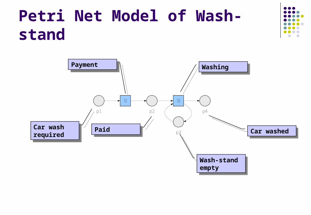
Petri Net Model of Wash-stand
Car wash required
Car wash required PaidPaid
Wash-stand empty
Wash-stand empty
Car washedCar washed
PaymentPaymentWashingWashing

Process Simulation using Petri NetCar wash required
Payment Paid
Wash-stand empty
Washing Car washed
Car wash required
Payment Paid
Wash-stand empty
Washing Car washed
Car wash required
Payment Paid
Wash-stand empty
Washing Car washed
Car wash required
Payment Paid
Wash-stand empty
Washing Car washed
Car wash required
Payment Paid
Wash-stand empty
Washing Car washed
Initial state: tokens are in places Car wash required and Wash-stand empty.
Transition Payment fired. Token is removed from the input place Car wash required.
Payment is finished. Token is put in place Paid. Transition Washing is enabled.
Transition Washing is fired. Tokens are removed from its input places.
Final state. Tokens are moved to Car washed and Wash-stand empty places.
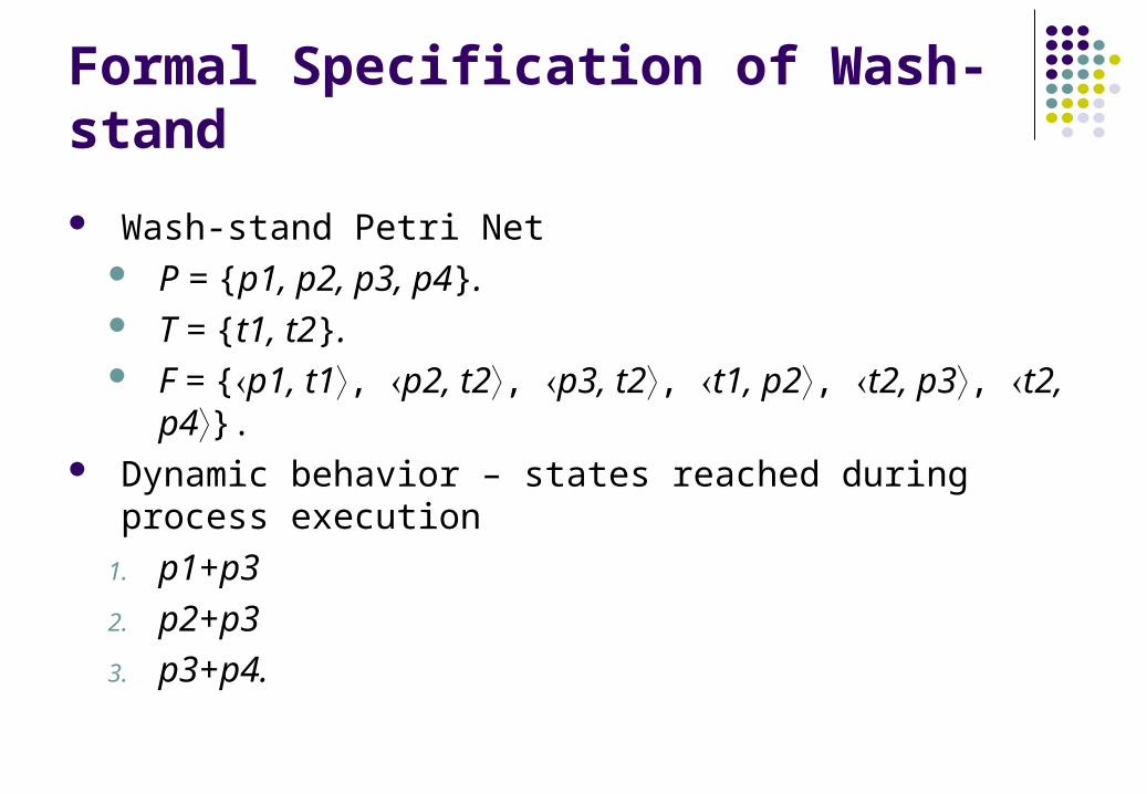
Formal Specification of Wash-stand
Wash-stand Petri Net P = {p1, p2, p3, p4}. T = {t1, t2}. F = {p1, t1, p2, t2, p3, t2, t1, p2, t2, p3, t2, p4}.
Dynamic behavior – states reached during process execution
1. p1+p3
2. p2+p3
3. p3+p4.
Significant Properties of Petri Nets
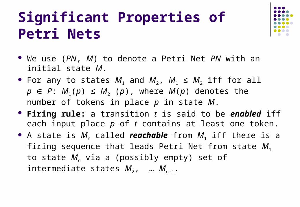
We use (PN, M) to denote a Petri Net PN with an initial state M.
For any to states M1 and M2, M1 ≤ M2 iff for all p P: M1(p) ≤ M2 (p), where M(p) denotes the number of tokens in place p in state M.
Firing rule: a transition t is said to be enabled iff each input place p of t contains at least one token.
A state is Mn called reachable from M1 iff there is a firing sequence that leads Petri Net from state M1 to state Mn via a (possibly empty) set of intermediate states M2, … Mn-1.
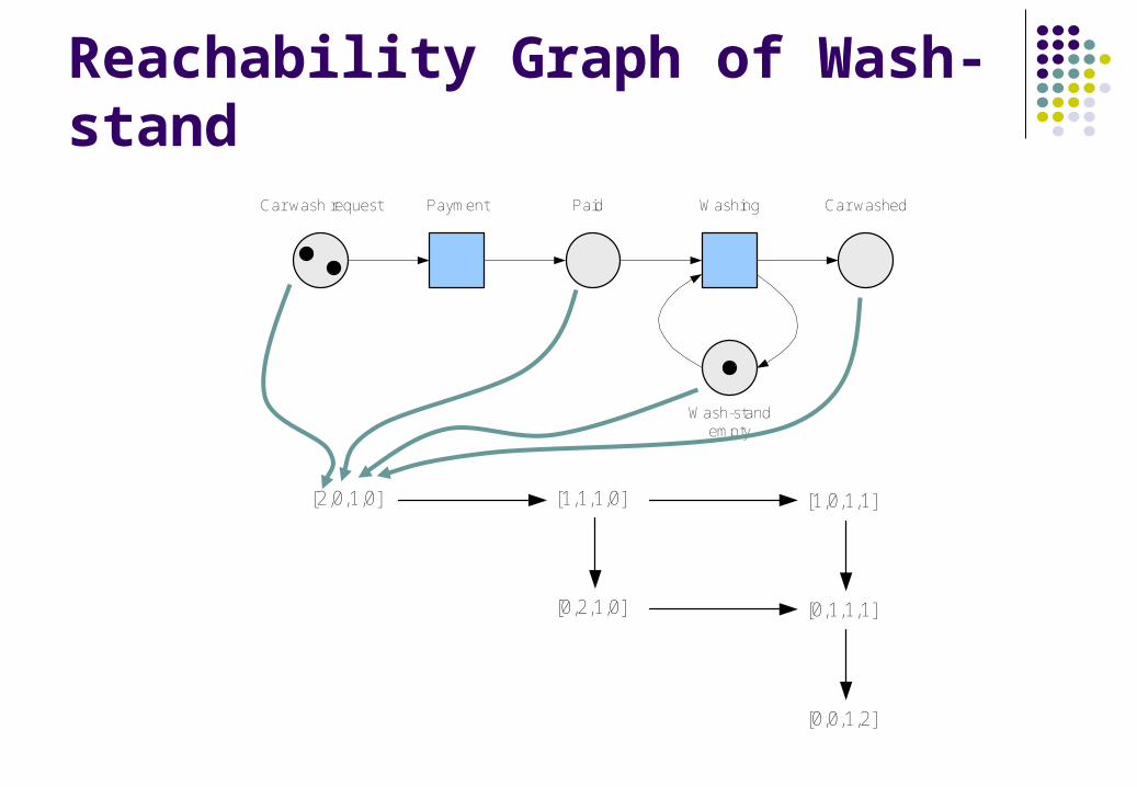
Reachability Graph of Wash-standCar wash request Payment Paid
Wash-stand empty
Washing Car washed
[2,0,1,0] [1,1,1,0] [1,0,1,1]
[0,2,1,0] [0,1,1,1]
[0,0,1,2]

Traffic Lights Petri Net
p1: Red
p2: Yellow
p3: Green
yr
rg
gy
[1,0,0] [0,0,1]
[0,1,0]
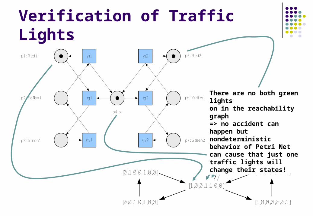
Verification of Traffic Lightsp1: Red1
p2: Yellow1
p3: Green1
yr1
rg1
gy1
yr2
rg2
gy2
p5: Red2
p6: Yellow2
p7: Green2
p4: x
[1,0,0,1,1,0,0]
[0,1,0,0,1,0,0] [1,0,0,0,0,1,0]
[0,0,1,0,1,0,0] [1,0,0,0,0,0,1]
Initial marking M0Initial marking M0
There are no both green lights on in the reachability graph => no accident can happen but nondeterministic behavior of Petri Net can cause that just one traffic lights will change their states!

Correct Model of Traffic Lightsp1: Red1
p2: Yellow1
p3: Green1
yr1
rg1
gy1
yr2
rg2
gy2
p6: Red2
p7: Yellow2
p8: green2
p4: x1 p5: x2
[1,0,0,1,0,1,0,0]
[1,0,0,0,0,0,0,1]
[1,0,0,0,0,0,1,0]
[1,0,0,0,1,1,0,0]
[0,0,1,0,0,1,0,0]
[0,1,0,0,0,1,0,0]
Liveness and Boundness
A Petri Net (PN, M) is live iff for every reachable state M’ and every transition t there is a state M’’ reachable from state M’ that enables t (=> every transition can fire arbitrarily many times).
A Petri Net (PN, M) is bounded iff for each place there is a natural number n such that for every reachable state the number of tokens in place p is less than n. The net is safe iff for each place the maximum number of tokens does not exceed 1.

Live Petri Net
Car was required Payment Paid
Wash-stand empty
Washing Car washed
Car usage
Every transition can fire arbitrarily many times.

Colored Petri Net: Order Processing
Orderreceived
Considerorder
Orderrejected
Checkarticlesavailability
Articlesavailable?
Ship order
Ordershipped
Send bill
Payment not paid
Checkpayment
Order completed
Purchase material
Material available
Produce articles
Orderaccepted?
t1
t1
t2
Purchase ready
t3
t4
Payment completed?
Empty transition required by Petri Net formalism.
Empty transition required by Petri Net formalism.
Token carries information needed for deterministic execution of Petri Net.
Token carries information needed for deterministic execution of Petri Net.
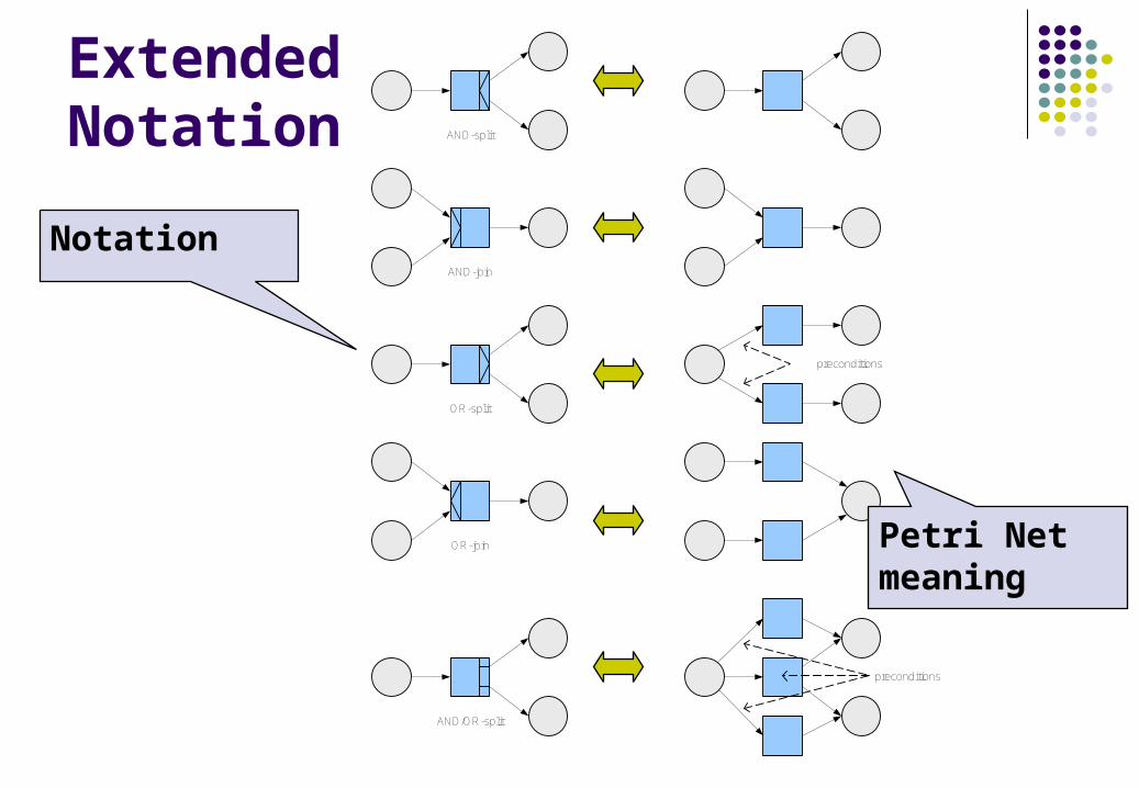
Extended Notation AND-split
AND-join
OR-split
preconditions
OR-join
AND/OR-split
preconditions
Notation
Petri Net meaning

Modified Petri Net:Order Processing
Orderreceived
Considerorder
Order rejected
Checkarticlesavailability
Articlesavailable
Ship order
Ordershipped
Sendbill
Payment not done
Checkpayment
Order completed
Purchase material
Make production plan
Material available
Plan available
Produce articles
Orderaccepted
Begin production
Purchase ready
Articlesto produce
Articles must be produced
Extended notation makes process model closer to reality while all properties of Petri Net theory is preserved.
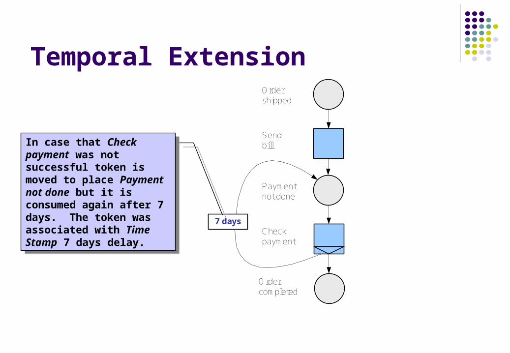
Temporal ExtensionOrder shipped
Sendbill
Payment not done
Check payment
Order completed
7 days
In case that Check payment was not successful token is moved to place Payment not done but it is consumed again after 7 days. The token was associated with Time Stamp 7 days delay.
In case that Check payment was not successful token is moved to place Payment not done but it is consumed again after 7 days. The token was associated with Time Stamp 7 days delay.
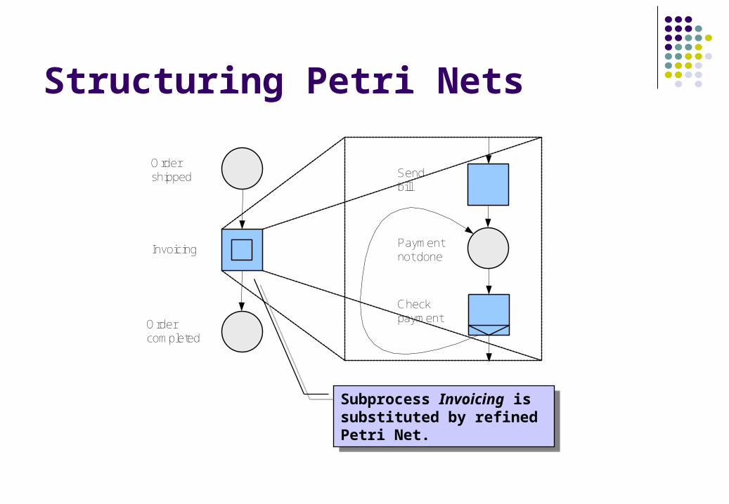
Structuring Petri Nets
Sendbill
Payment not done
Checkpayment
Ordershipped
Invoicing
Ordercompleted
Subprocess Invoicing is substituted by refined Petri Net.
Subprocess Invoicing is substituted by refined Petri Net.

Exercise 5
Create Petri Net model of Traffic Lights where the yellow light is on when lights are switching from red to green and back from green to red.
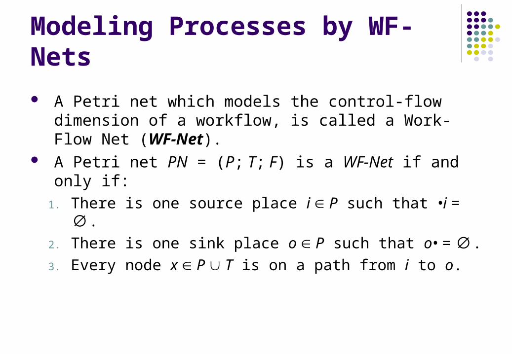
Modeling Processes by WF-Nets
A Petri net which models the control-flow dimension of a workflow, is called a Work-Flow Net (WF-Net).
A Petri net PN = (P; T; F) is a WF-Net if and only if:
1. There is one source place i P such that •i = ∅.
2. There is one sink place o P such that o• = ∅.
3. Every node x P T is on a path from i to o.

Workflow Structuresx y
Sequence
x
y
Implicit selection
x
Explicit selection
Concurrency
x
x
y
While-Do Loop
y
Repeat-Until Loop
x

WF-Net:Order Processing
Start
Considerorder
Orderrejected
Checkarticlesavailability
Articles available
Shiporder
Ordershipped
Sendbill
Payment not done
Checkpayment
Ordercompleted
Purchase material
Material available
Produce articles
Orderaccepted
Begin production
Purchase ready
Articles must be produced
End
Make production plan
Plan available
Articlesto produce
Closeorder
Beginning of the processBeginning of the process
End of the processEnd of the process
Resource initiative triggerResource initiative trigger
Time signal triggerTime signal trigger
External event triggerExternal event trigger
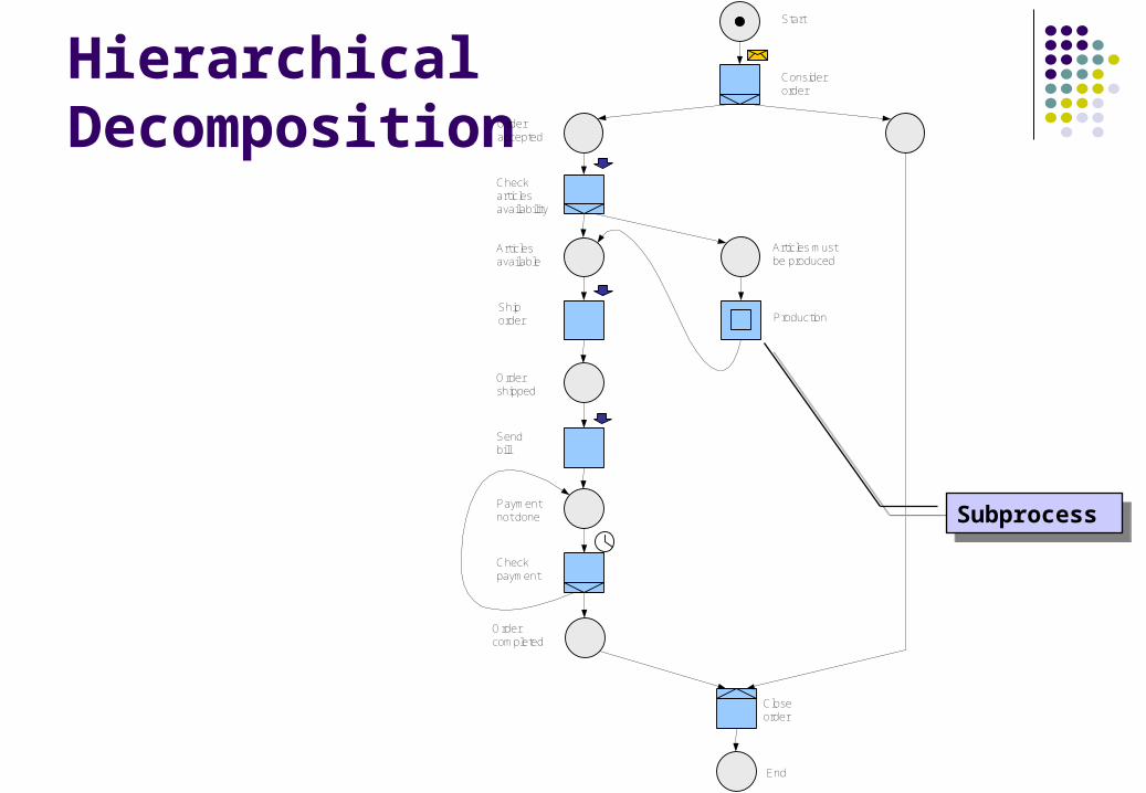
Hierarchical Decomposition
Start
Considerorder
Checkarticlesavailability
Articles available
Shiporder
Ordershipped
Sendbill
Payment not done
Checkpayment
Ordercompleted
Production
Orderaccepted
Articles must be produced
End
Closeorder
SubprocessSubprocess

Exercise 6
Create WF-Net for the process of delivery service. Let’s have activities Accept Order, Send Bill, Accept Payment, Ship Order and Cancel Order. When the order is accepted the bill is sent to customer. In case that the payment is not received in a given time interval order is canceled. If payment is received in time then the order is shipped to customer.

Analysis of Business Processes
Analysis of business processes is based on analysis of properties inherent to Petri Nets: reachability liveness boudness and others …
For the purpose of correct design of workflow property soudness was introduced.
Soudness A procedure modeled by WF-Net PN = (P, T, F) is sound if
and only if: For every state M reachable from state i, there exists a firing
sequence leading from state M to state o. State o is the only state reachable from state i with at least
one token in place o. There are no dead transition in (PN, i).
The first requirement states that starting from the initial state (state i), it is always possible to reach the state with one token in place o (state o). The second requirement states that the moment a token is put in place o, all the other places should be empty. Sometimes the term proper termination is used to describe the first two requirements. The last requirement states that there are no dead transitions in the initial state i.

Reachability Graph for Order ProcessingStart
Orderrejected
Articlesavailable
Ordershipped
Paymentnot done
Ordercompleted
Materialavailable
Orderaccepted
Purchaseready
Articles mustbe produced
End
Planavailable
Articlesto produce
+
Articlesto produce
+Purchaseready
+Planavailable
Materialavailable
+
Start state – token is in place Start.
Start state – token is in place Start.
Intermediate state – tokens are in places Purchase ready and Articles in produce at the same time.
Intermediate state – tokens are in places Purchase ready and Articles in produce at the same time.
Final state – token is in place End.
Final state – token is in place End.
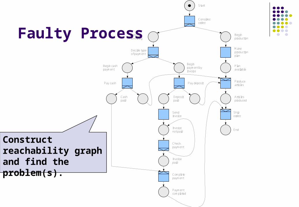
Faulty Process
Start
Considerorder
Beginproduction
Begininvoicing
Makeproductionplan
Decide typeof payment
Planavailable
Begin payment byinvoice
Begin cashpayment
Pay cash
Cashpaid
Pay depositProduce articles
Articlesproduced
Depositpaid
Send invoice
Invoice not paid
Checkpayment
Invoicepaid
Completepayment
Paymentcompleted
Shiporder
End
Construct reachability graph and find the problem(s).
Verification of Soundness The first method how to determine soudness requires to add an additional
transition t* that connects start place i with end place o (short-circuited net). Based on that the soudness of of the WF-Net corresponds with two properties: liveness and boundness of short-circuited net. The issue is that verification of liveness and boudness requires computer tools for complex process models.
The second method is based on the construction process of correct workflow nets. If we have two sound and safe WF-Nets WF1 and WF2 and we have transition t in WF1 which has just one input and one output place, then we may replace task t in WF1 by WF2 and the resulting WF-Net is sound and safe again. The safety is required because in case that input place of substituted
transition t contains more than one token the inserted WF-Net does not need to be sound.

Sound and Safe Components
x
Basic block
x y
Sequence
x
y
Implicit selection
x
y
Explicit selection
x
y
Concurrency
x
y
Loop

Well-structured WF-Nets
Well-structured WF-Net contains balanced AND/OR-splits and AND/OR-joins. It means that two concurrent flows initiated by AND-split should not be joined by OR-join. Two alternative flows created via OR-split cannot be synchronized by AND-join.
The main advantage of using well-structured nets is that sound and well-structured WF-Nets are also safe. It means that based on using of sound and well-structured components these components are also safe and we can build new sound and well-structured WF-Nets (and components).

Building Sound WF-Nets from ComponentsStart
End
Orderprocessing
Considerorder
Processorder
End
Orderaccepted
Ordercompleted
Orderrejected
Closeorder
Considerorder
Invoicing
End
Orderaccepted
Ordercompleted
Closeorder
Check articles availability
Articles mustbe produced
Production
Articlesproduced
Articlesavailable
Shiporder
Ordershipped
Considerorder
Providearticles
End
Orderaccepted
Ordercompleted
Orderrejected
Closeorder
Ordershipped
Invoicing
Start Start Start

Building Sound WF-Net cont.
Considerorder
Cashing
End
Orderaccepted
Ordercompleted
Orderrejected
Closeorder
Check articles availability
Articles must be produced
Articlesproduced
Articlesavailable
Shiporder
Ordershipped
Purchasematerial
Materialavailable
Produce articles
Purchase ready
Makeproductionplan
Planavailable
Articles to produce
Sendbill
Paymentnot done
Start
Beginproduction
Considerorder
Checkpayment
End
Orderaccepted
Ordercompleted
Orderrejected
Closeorder
Check articles availability
Articles must be produced
Articlesproduced
Articlesavailable
Shiporder
Ordershipped
Purchasematerial
Materialavailable
Produce articles
Purchase ready
Makeproductionplan
Planavailable
Articles to produce
Sendbill
Paymentnot done
Outstanding
Beginproduction
Formalization and Verification of Processes
Key issues of formal methods: Formal methods reduce number of errors in process
specification but the mathematical representation requires more time to obtain results.
Formal methods are hard to scale up to large systems. The main area of their applicability is critical systems. In this
area the use of formal methods seems to be cost-effective. Formalization of informally defined processes:
The idea is to combine formal methods with diagrammatic languages like EPC or UML.

EPC Formalization An event-driven process chain is a five-tuple EPC = (E, F, C, T, A) :
E is a finite set of events, F is a finite set of functions, C is a finite set ogf logical connectors, is a function which maps each connector onto a
connector type,
is a set of arcs. Next step is to define rules of how the EPC model can be transformed to WF-
Net. Resulting WF-Net can be verified using standard methods and tools applicable to
Petri Nets. Building of EPC diagrams can employ well-structured components as well as
constructing WF-Nets.
,,: XORCT
CCFCCFECCEEFFEA
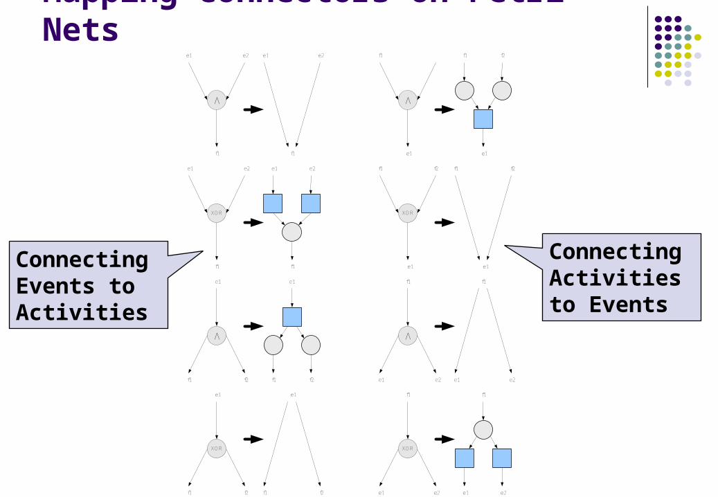
Mapping Connectors on Petri Nets
V
XOR
V
XOR
e1 e1
e1 e1
e1 e1
e1 e1
e2 e2
e2 e2
f1 f1
f1 f1
f1 f1
f1 f1
f2 f2
f2 f2
V
XOR
V
XOR
e1 e1
e1 e1
e1 e1
e1 e1
e2 e2
e2 e2
f1 f1
f1 f1
f1 f1
f1 f1
f2
f2 f2
Connecting Events to Activities
Connecting Activities to Events

Transformation of EPC Model to Petri Net
Event 1 Event 2 Event 3
XOR
Event 1 Event 2 Event 3
XOR
Activity X
Event X
V
Activity 1
Event 4
V
Activity 1
Event 4
Event 1 Event 2
Event 4
Activity 1
Activity X
Event X
Arcs between two connectors must be replaced by events and functions before the EPC is mapped onto a Petri Nedt.
Arcs between two connectors must be replaced by events and functions before the EPC is mapped onto a Petri Nedt.
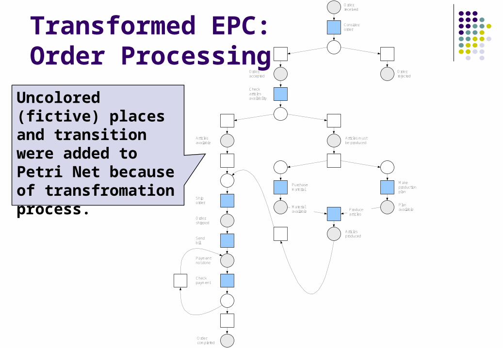
Transformed EPC:Order Processing
Orderreceived
Considerorder
Orderrejected
Orderaccepted
Check articles availability
Articlesavailable
Shiporder
Ordershipped
Sendbill
Paymentnot done
Checkpayment
Ordercompleted
Articles must be produced
Purchasematerial
Makeproductionplan
Materialavailable
PlanavailableProduce
articles
Articlesproduced
Uncolored (fictive) places and transition were added to Petri Net because of transfromation process.

Exercise 7
Transform the give process model specified in EPC diagram to Petri Net. Is this process sound?
Articles must be produced
V
Purchase material
Make production
plan
Material available
Plan available
V
Produce articles
Articlesproduced

Software Tools
ARchitecture of Integrated Systems (ARIS) Business Process Studio (BP Studio)

Architecture of Integrated Systems
Conceptual Framework that helps to describe organizations: their organizational structure, their processes and their resources in terms of people and information systems.
Software tool that helps to apply the conceptual framework. The software tool helps to electronically describe organizations in a consistent manner and analyze them in some respects.
More at … http://www.ids-scheer.com

ARIS Framework
Management
SalesManufacture
Sale
Process request
Process offer
Check production
Determine delivery date
Request accepted
Process request
Request processed
Process offer
Offer Request
Customer
SalesRequest
Organizational view
Data view Control view Functional view
Business Process Studio
BPStudio is user friendly, so domain experts without a special knowledge of information technology can use it.
BPStudio is based on a formal approach (Petri Nets) that enables analysis, simulation, and later execution of a built model (workflow engine).
BPStudio is focused on concurrency as a primary and inherent property of any business process
Download … http://vondrak.cs.vsb.cz/download.html
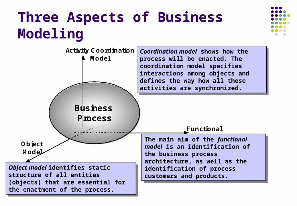
Three Aspects of Business Modeling
FunctionalModel
Activity CoordinationModel
ObjectModel
BusinessProcess
The main aim of the functional model is an identification of the business process architecture, as well as the identification of process customers and products.
The main aim of the functional model is an identification of the business process architecture, as well as the identification of process customers and products.
Object model identifies static structure of all entities (objects) that are essential for the enactment of the process.
Object model identifies static structure of all entities (objects) that are essential for the enactment of the process.
Coordination model shows how the process will be enacted. The coordination model specifies interactions among objects and defines the way how all these activities are synchronized.
Coordination model shows how the process will be enacted. The coordination model specifies interactions among objects and defines the way how all these activities are synchronized.

Functional Model: Car Sale
Process Customer
Process Customer
Process Owner
Process Owner
Process Product
Process Product
Process Process
Collaboration relationship exhibits a possibility of concurrent existence of processes
Collaboration relationship exhibits a possibility of concurrent existence of processes
Contains relationship means that a process launches contained process and finishes it when required products are obtained
Contains relationship means that a process launches contained process and finishes it when required products are obtained

Functional Model: Financing
External Process is not elaborated in a given “Car Sale” process model
External Process is not elaborated in a given “Car Sale” process model

Functional Model: Car Hand Over
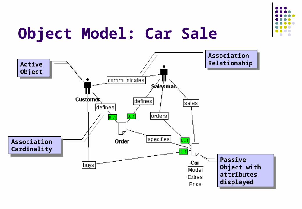
Object Model: Car Sale
ActiveObject
ActiveObject
Passive Object with attributes displayed
Passive Object with attributes displayed
AssociationRelationship
AssociationRelationship
AssociationCardinality
AssociationCardinality

Object Model: Financing
Generalization/SpecializationRelationship
Generalization/SpecializationRelationship

Object Model: Car Hand Over
Active Object with attributes and services displayed
Active Object with attributes and services displayed

Coordination Model: Car Sale
Activity with specified scenarios, their costs and durations
Activity with specified scenarios, their costs and durations
Contained processContained process
ForkFork

Coordination Model: Financing
BranchingBranching
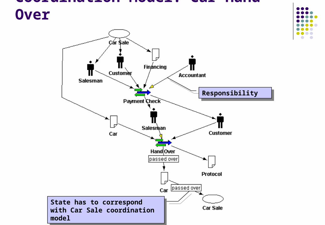
Coordination Model: Car Hand Over
ResponsibilityResponsibility
State has to correspond with Car Sale coordination model
State has to correspond with Car Sale coordination model
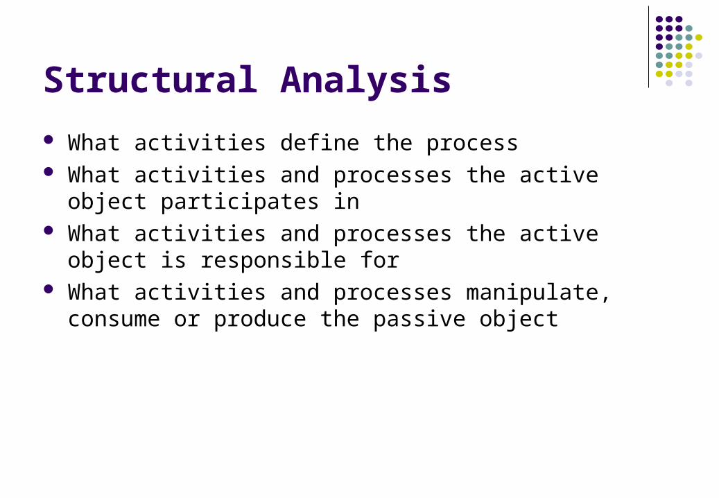
Structural Analysis
What activities define the process What activities and processes the active object participates in What activities and processes the active object is responsible
for What activities and processes manipulate, consume or
produce the passive object
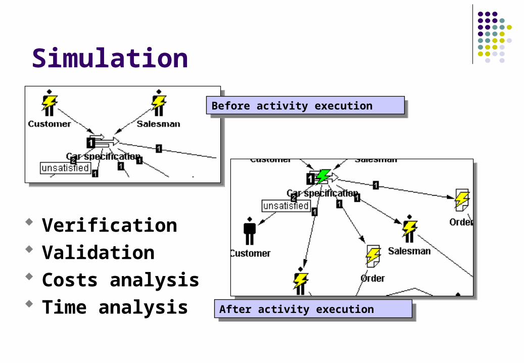
Before activity executionBefore activity execution
After activity executionAfter activity execution
Simulation
Verification Validation Costs analysis Time analysis
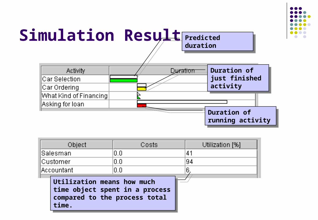
Simulation ResultPredicted durationPredicted duration
Duration of just finished activity
Duration of just finished activity
Duration of running activity
Duration of running activity
Utilization means how much time object spent in a process compared to the process total time.
Utilization means how much time object spent in a process compared to the process total time.

Cloning
Process model describes how the process should look. Process is simulated by a computer.
Process model describes how the process should look. Process is simulated by a computer.
Process instance represents real process that exists and humans execute it using tools like machines, computers etc.
Process instance represents real process that exists and humans execute it using tools like machines, computers etc.
Process Enactment

BPStudio Architecture
ORB
BP Actor
Web BrowserBP Actor
BP Model
Model Repository
Web BrowserBP Viewer
BP Control
Instance Repository

Conclusions
Common methods for business modeling were introduced: IDEF, EPC and UML.
Importance of formal methods and their contribution to business process modeling were demonstrated.
Software tools ARIS and BPStudio were introduced to show how eEPC and Petri Nets can be used in practice.

Solution to Exercise 1
TITLE:NODE: NO.:A5 Fakurace a inkaso
1
Invoice sending
2
Payment Checking
Bill of sale
Bill sent
Bill sent
Order closed
Bank statement
Accounting department

Solution to Exercise 2
Articles mustbe produced
V
Purchase material
Make production
plan
Materialavailable
Planavailable
V
Producearticles
Articlesproduced
Check material
availability
V
Material in stock
Material shipped
V
Material must be purchased
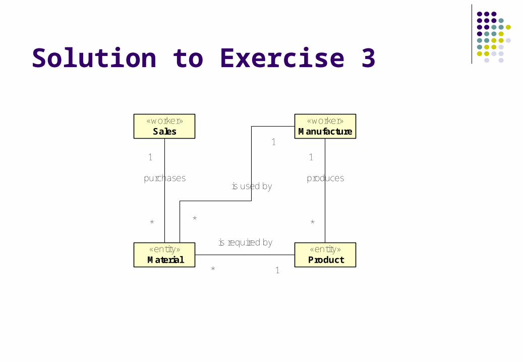
Solution to Exercise 3
«worker»Sales
«entity»Material
«entity»Product
«worker»Manufacture
1
*
purchases
* 1
is required by
1
*
produces
*
1
is used by

Solution to Exercise 4ManagerAccountant
Invoice drawing
Authorization
Invoice sending
[amount > 5000 USD]
[amount <= 5000 USD]
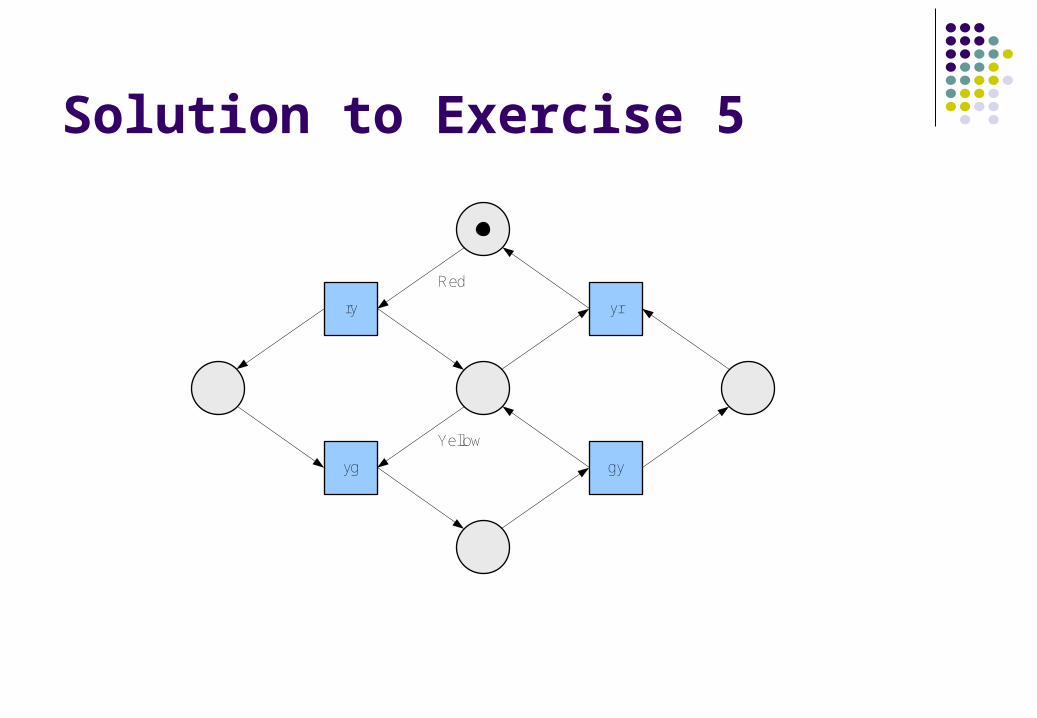
Solution to Exercise 5
yrry
gyyg
Red
Yellow

Solution to Exercise 6Start
Acceptorder
Orderaccepted
Sendbill
Billsent
Acceptpayment
Paymentaccepted
Shiporder
End
Cancelorder
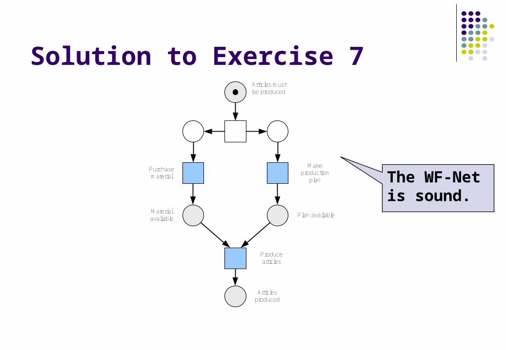
Solution to Exercise 7Articles must be produced
Articlesproduced
Purchase material
Material available
Make production
plan
Plan available
Produce articles
The WF-Net is sound.


