GkAfjJfWiTTO* BT CENTRAL RESEARCH LIBRARY DOCUMF TION ORNL 1463 Metallurgy and^Ceraaics 3 44Sb D3S316S ^ •7^ £/ METHODS OF FABRICATION OF CONTROL AND SAFETY ELEMENT COMPONENTS FOR THE AIRCRAFT AND HOMOGENEOUS REACTOR EXPERIMENTS CENTRAL RESEARCH LIBRARY DOCUMENT COLLECTION LIBRARY LOAN COPY DO NOT TRANSFER TO ANOTHER PERSON If you wish someone else to see this document, send in name with document and the library will arrange a loan. <&) Oak Ridge National Laboratory OPERATED BY Carbide and Carbon chemicals company A DIVISION OF UNION CARBIDE AND CARBON CORPORATION POST OFFICE BOX P OAK RIDGE. TENNESSEE
Transcript
GkAfjJfWiTTO*
BT
CENTRAL RESEARCH LIBRARY
DOCUMF TION
ORNL 1463
Metallurgy and^Ceraaics
3 44Sb D3S316S ^
•7^£/
METHODS OF FABRICATION OF CONTROL AND
SAFETY ELEMENT COMPONENTS FOR THE
AIRCRAFT AND HOMOGENEOUS
REACTOR EXPERIMENTS
CENTRAL RESEARCH LIBRARY
DOCUMENT COLLECTION
LIBRARY LOAN COPY
DO NOT TRANSFER TO ANOTHER PERSON
If you wish someone else to see this document,send in name with document and the library willarrange a loan.
<&)
Oak Ridge National LaboratoryOPERATED BY
Carbide and Carbon chemicals companyA DIVISION OF UNION CARBIDE AND CARBON CORPORATION
POST OFFICE BOX P
OAK RIDGE. TENNESSEE
ORNL-1463
Thi» document conaiata of 1| pagaa.
Copy 6 of 159 copiea. Seriaa A.
Contract No. W-7405, eng-26
METALLURGY DIVISION
METHODS OF FABRICATION OF CONTROL AND SAFETY ELEMENT COMPONENTS
FOR THE AIRCRAFT AND HOMOGENEOUS REACTOR EXPERIMENTS
J. H. Coobs and E. S. Bomar
Powder Metallurgy by J. H. Coobs and E. S. Bomar
Welding and Brazing by G. M. Slaughter and P. Patriarca
DECLASSIFIEDCUssrF.rr,flAT-M?§fi|?f?To.
FEB 2 6 1953
OAK RIDOE NATIONAL LABORATORY
Operated by
CARBIDE AND CARBON CHEMICALS COMPANY
A Division of Union Carbide and Carbon Corporation
Post Office Box P
Oak Ridge, Tennessee
3 MMSb D3S316S ^
li
INTEM DISTRIBUTION
ORNL-1463
Metallurgy and Ceramics
1. C. E. Center 27. A. Ho llaender j^M2. Biology LibraryT 28. M. T. Kelley W3. Health Physics Libi 29. K. Z. Morgan ^m4. Metallurgy LibrajH 30. J. S. Felton^^
5-6. Centr al Researcj^H Lbrary 31. A. S. Housej^Vder7. Re actor ExperiiVt al 32. C. s. Harri^v
Engineering^fl prary 33. C. E. Win^K8-13. Central Fil^^P 34. D. S. Bi^Hngton
14. C. E. Lars^^F 35. D. w. G^Vwel 115. W. B. Hun^T(K- 25) 36. E. M. ^fg16. L. B. Ej^Tt (Y- 12) 37. A. jj •filer17. A. M. JvLnberg 38. D. ICowen18. E. HjVay lor 39. PJ Reyling19. E. Bhipley 40. K. Williams
20. ¥j VonderLage 41. 'h. Coobs
21. W-" Briant 42 J ^7. s. Bomar
22. \J. Fretague AjM JG. M. Slaughter23J ^^m% A. Swartout P. Pa triarca
2M FS. C. Lind ^^V. A. Levy (on loan fromF. L. Steahly P ratt and WhitneyA. H. Snell A ircraft)
EXTERNAL DISTRIBl,
46-53. Argonne National Lai54-58. Atomic Energy Comm^^^^PT, Washington
65-66. Cali fornd^prTesearch and Development Company67-68. Carbidj^Vd Carbon Chemicals Company (K-25 Plant)69-72. Carbj^^p&nd Carbon Chemicals Company (Y-12 Plant)
73. Chj^Hfo Patent Group74. Dow Chemical Company (Rocky Flats)
75-77. duPont Company
c84.
9C1-93194
95 -98.
99-•101.
102
103
104-•106
107
108
109
110
111
112
113 -117
118 -120
121
122
123
124
125
126
127 -130
131
132 -135
136 -144
145 -159
General Electric Company (ANPP) (1 copy eaH. C. Brassfield, J. A. McGurty, and W. J
General Electric Company, RichlandkHanford Operations Office
laho Operations OfficeState College.s Atomic Power Laboratory
Lo^^^Lamos Scientific LaboratoryMa^L^^^rodt Chemical WorksMassl^^^etts Institute of Technology (Kaufmann)
to W. Baxter,Koshuba)
Mound
Nation
National
National Bi
National L
Naval Resear
New Brunswick L
New York OperatNorth American Av
Patent Branch, Wash1Rand CorporationSan Francisco OperatiSavannah River Operatio:Savannah River Operati
itory
ory Committee for Aeronautics, Clevelandory Committee for Aeronautics, Washington
f Standards
any of Ohiooratory
tory
Office
n, Inc.on
jea(
Sylvania Electric Products,University of California Ra<Walter Kidde Nuclear Laborato:Westinghouse Electric CorporatiWright Air Development Center (1Pratt and Whitney Aircraft)
Technical Information Service, Oak
AugustaWilmington
LaboratoryInc.
to R. Strough,
in
I *>
t*'*>• •?
* 'W* *# ^
METHODS OF FABRICATION OF CONTROL AND SAFETY ELEMENT COMPONENTSFOR THE AIRCRAFT AND HOMOGENEOUS REACTOR EXPERIMENTS
J. H. Coobs and E. S. Bomar
SUMMARY
This report contains, in two parts,the experimental work leading to thefabrication of control and safetycomponents for the Aircraft andHomogeneous Reactor Experiments.
The method evolved for preparationof cylindrical inserts for the AREcontrol and safety rods required thehot-pressing of mixtures of boroncarbide with alumina and with iron.
A technique for fabrication ofcontrol plates for the HRE was devisedto minimize defects found in earlier
sets of plates. The method involvedclosely packing pressed-powder compacts in a frame and then hot-rollingto bond protective cladding sheets tothe core.
INTRODUCTION
The neutron-absorbing materialselected for control and safetyelements in both the ARE and HRE was
boron in the carbide form.
Cylinders with acceptable physicalproperties and the requisite amountof boron were made for the ARE safetyrods by consolidating mixed iron andboron carbide powders. Consolidationwas effected by pressing at an elevatedtemperature. Inserts for the controlelements were prepared in a similarmanner by using a dilute suspension ofboron carbide in alumina as a carrier.
The operating conditions to whichthe HRE control and safety plates areexposed require that the high cross-section material be completely enclosedin a protective envelope. Initially,efforts were directed toward the
cladding of Boral with stainless steelas a protective covering. Later,pressed and sintered compacts of boroncarbide suspended in copper were substituted for the Boral to permit
rolling at a higher temperature forbonding of cladding to core.
ARE CONTROL AND SAFETY ROD COMPONENTS
The design selected for the controland safety rods for the ARE called forthe use of boron carbide as the highcross - section material. Inserts for
the control rod were to be made in the
form of cylinders and composed of adilute suspension of boron carbide inalumina. These were later preparedwith a minimum of difficulty.
The boron carbide bearing componentsfor the safety rods were to have essentially the same shape, but were tobe made of pure boron carbide. Thereply to an inquiry to a supplier ofthe special grade of boron carbiderequired for the pure boron carbidepressed cylinders indicated that thecost for these items would be quitehigh. Therefore experimental work wasdone which revealed that pressedcylinders containing an acceptableamount of boron carbide bonded with
iron could be produced.Experimental Work on Safety Rod
Inserts. Mixtures containing 80 vol %boron carbide (Norton, metallurgicalgrade, which analyzed 71 + 1% boron)and 20 vol % copper, nickel, and ironwere hot-pressed to check the usefulness of these materials as cementingagents. The powders used were all-325 mesh, and were milled together,using steel balls, for several hours.
The results of these runs are
tabulated in Table 1. The results of
the first runs indicated that nickel
did not promote especially desirableproperties in the pressed compact. Aliquid phase formed, but it did notwet the boron carbide particles andgave little cementing action.
TABLE 1. PROPERTIES OF HOT-PRESSED NICKEL, COPPER, AND
Copper gave somewhat better cementingeffect than the nickel even though itdid not dissolve appreciable amountsof boron or carbon. In every instance,however, a portion of the copper waslost by extrusion past the rams, andthe resulting compacts were still tooporous and weak to be useful.
The initial runs in which iron was
used as the bonding agent were alsounsatisfactory, being too soft andporous. There was, however, noevidence of loss of iron during thepressing cycle; the iron may havebeen converted to solid FeB or Fe3C.This is confirmed by the work ofNelson, Willmore, and Womeldorph,(1>who pressed and sintered mixtures of20 wt % iron (7.5 vol %) and 80 wt %boron carbide at1930°C for 30 minutes.
These sintered bodies were fairlystrong and underwent some shrinkage,with no loss of material. Examinationby x-ray-diffraction techniques failedto detect iron, but revealed thepresence of FeB, B4C, and graphite.It thus seems that the bonding phaseis FeB formed by reaction of iron and
(l)'J. A. Nelson, T. A. Willmore, and H. C.Woneldorph, J. Electrochem. Soc. 98, No. 12, 465(1951).
and ft. C.
boron carbide during the sinteringcycle.
On the basis of these conclusions,several runs were made at highertemperatures; the results are shown inTable 2. After several runs a hot-
pressing cycle of 5 min at 1525 to1535°C was selected. This schedule
gave well-bonded slugs having adensityclose to 80% of theoretical with only3 to 4% loss of material during press-in g.
Production of Safety Rod Inserts.
Having selected boron carbide and ironas the combination to be used, quantities of the powders were prepared togive 80 vol % (56 wt %) boron carbideand 20 vol % iron. Coarse boron
carbide powder was reduced to a finepowder by grinding for 16 hr in asteel ball mill with steel balls. The
sieve analysis of this material isgiven in Table 3. The requisite amountof -325 mesh iron powder was thenblended with the boron carbide bygrinding for an additional 8 hr in thesame mill.
The mixture was consolidated byhot-pressing at 1520 to 1530°C and2500-psi pressure in graphite dies.
TABLE 2. ADDITIONAL PROPERTIES OF HOT-PRESSED IRON PLUS BORON CARBIDE COMPACTS
COMPOSITION
(vol %)
PRESSING
TEMPERATURE
(°C)
DENSITY AS PERCENTAGE
OF THEORETICAL
DENSITY
LOSS
(*)REMARKS
20 Fe-80 B4C 1520 77.6 Strong
20 Fe-80 B4C 1725 70.5 29 Weak
7.5 Fe-92.5 B4C 1740 68.2 6.0 Fairly strong
20 Fe-80 B4C 1520 80.0 3.0 Strong
20 Fe-80 B4C 1520 77.8 4.2 Strong
20 Fe-80 B4C 1525 80.3 5.5 Strong
20 Fe-80 B4C 1530 77.8 6.5 Strong
20 Fe-80 B4C 1525 79.0 6.5 Strong
20 Fe-80 B4C 1520 78.3 8.0 Strong
Densities approximately 80% of theoretical for the mixture were obtainedunder these conditions. One of the
assemblies used for the pressingoperation is shown in Fig. 1.
For assembly, the long punch andmandrel were placed in the die with
TABLE 3. SIEVE ANALYSIS OF
BORON CARBIDE POWDER
+100 mesh
-100 +200 mesh
-200 +325 mesh
-325 mesh
1.2%
17.2%
18.8%
62.8%
UNCLASSIFIED
Y-7089
Fig. 1. Graphite Die Assembly.
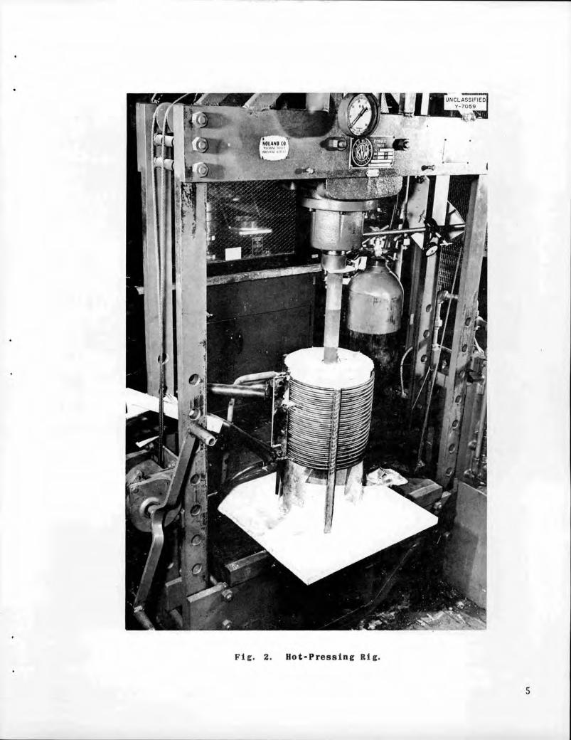
the mandrel centrally located along The hot-pressed slugs were groundthe axis of the die. The punch extended to within the limits of tolerance forout of the bottom of the die. A length with a diamond wheel and brazedcharge of 132 to 133 g of blended into a finished assembly, as shown inpowder was then loaded into the annular Fig. 3. The brazing operation wasspace between the die and mandrel, the carried out in a hydrogen atmosphere,top punch put in place, and a load of and Nicrobraz alloy was used.2000 psi applied to seat the punches Experimental Work on Control Rodprior to placing in the hot-pressing Inserts. The first step in the workrig. The set-up for hot-pressing is on control rod inserts was toestablishshown in Fig. 2. the compatibility of aluminum oxide
The lower punch rested on a graphite and boron carbide at the elevatedblock, which, in turn, was insulated temperature used for fabrication. Afrom a Transite base by two refractory preliminary slug, less than full size,bricks (Norton, RA 1190). A quartz was hot-pressed at 1750°C for 5 minliner served as a retainer for the from a mixture of 90 vol % aluminumbubble-alumina insulation poured in oxide (Norton, grade 38-500) and 10around the graphite die prior to v°l % boron carbide (Norton, metal-heating. The quartz cylinder was, in lurgical grade). The powder was con-turn, externally supported by a tained in a graphite die and con-Transite sleeve that extended up to solidated at a pressure of 2500 psi.the induction coil. Power was supplied Meta11ographic examination revealedby an Ajax, 40-kw converter set at that the two materials were compatible.30 kw for heat-up and at about 15 kw A second slug containing the prescri bedto hold at temperature. An argon amount of -325 mesh boron carbide hadatmosphere was introduced at the a density 86% of theoretical andbottom of the assembly to decrease the possessed satisfactory physicalrate of oxidation of the graphite dies. properties.
T^ - , A full-size alumina-boron carbideIt was found necessary to use ,. , . . . ..... cylinder was pressed by using the
additional graphite spacers, as shown , .... ,„. o i above conditions oi temperature and
in rig. I, to prevent excessive heating _ . , , . ,:._. ,. . . - ,. pressure. Considerable difficulty was
of the press ram because ol coupling , . . , ,. , , r . .. , , , . , r . encountered in ejecting the slug from
with the magnetic field oi the induction , ,. ^u , ..... . . the die. lhere was also a marked
coil. A prism was mounted over the , - . . ... , .• i,. ,. i r ,i j • ,. .. , tendency lor the bubbl e - alumina in
sight tube ol the die so that optical , . . , ... i , , , • sulation to sinter at this temperature,
temperature readings could be made in 0 , , , . , ., . _ , . . A1 , Subsequently, another full-size slug
a horizontal position. Also, a low- , . c... , was pressed, and a maximum temperature
pressure gage was added to the press „ 1/rcrio,~ , r^,r _. • , r-, • , • , . ol IodvJ L was used. The compact waslor this work. This gage, which is . . , ,. ... ,
. . „. n . , removed without difficulty, andnot shown in rig. I. is connected to • ,. r ..u i .. • i8 ' sintering of the insulating materialthe hydraulic line above the gage , ™, , .. £ ,_,
, ' co was minimized, The density oi tne
second compact dropped to 80% ofIt was found necessary to push the theoretical but the physical properties
mandrel out of the slug at high temper- were still acceptable. The boronature to avoid cracking during cooling carbide investment was increasedbecause of a marked difference in proportionately to compensate for theexpansion coefficients for the boron decreased density.carbide compacts and graphite. The Production of Control Rod Inserts.mandrel was pushed out of the compact The hot-pressing equipment used forinto the lower punch by using an making the boron carbide-iron partsundersize mandrel. was also employed forproducing inserts
Fig. 2. Hot-Pressing Rig.
Fig. Assembly for Boron Carbide-Iron Slug.
for the control rods. New dies were
used, however, to avoid additionalboron pickup. Inserts for two rodswere to be made; one set with a boroncarbide con tent of 0.022 to 0.024 g/cm3,the other with a boron carbide content
of 0.005 to 0.006 g/cm3.A special grade of alumina was used
(Norton, grade 38-500). Batches ofabout 1 lb were prepared by mixingappropriate quantities of the aluminaand -325 mesh boron carbide (Norton,metallurgical grade). Fine boroncarbide powder was obtained by ball-milling relatively coarse stock andscreening out the desired fraction.Blending was carried out by tumblingin a glass jar for approximately 8hours. The boron carbide additions
were such as to give the correct boroninvestment for a hot-pressed compacthaving a density 80% of theoretical.
The technique for hot-pressing thealumina-boron carbide powder essentially duplicated that used on the
boron carbide—iron powder, except foran increase in maximum temperature to1650 C. Components for an assemblyand a completed unit are shown inFig. 4. The brazing operation wasagain done by using Nicrobraz alloy ina hydrogen atmosphere.
HRE CONTROL ELEMENTS
The design of the control elementsfor the HRE calls for plates bent intosemicircular shapes. The plates willbe exposed during operation of the HREto high-pressure water and gas. Theplates are to be made of a high cross-section material contained in a stain
less steel jacket. For the first setof elements built, sheet stock ofboron carbide dispersed in aluminumwas canned in type 347 stainless steelby covering the boron carbide stockwith the steel and edge- we 1ding.Several of these plates were found todistend following return to atmospheric
Fig. 4. Assembly for Boron Carbide-Alumlnun Oxide Slugs.
pressure after exposure to operatingpressures. Failure was accredited toan accumulation, as a result of leakagethrough porous welds, of high-pressuregas in the space between the claddingand insert. The porosity may have beencaused by melting and alloying of thealuminum with the weld metal.
The purpose of this investigationwas to determine a procedure of fabrication that would minimize the defects
found in the first set of plates.Hot-rolling was employed to eliminatethe void by bonding the cladding tothe core. In an effort to use ma
terials readily available, bonding ofthe boron carbide-aluminum sheet with
stainless steel was attempted first.Work was later shifted to the claddingof pressed-powder mixtures of boroncarbide suspended in copper, sincethis method appeared to offer a betterchance for success in the limited time
available for the work.
Reproducibility of the quality ofthe edge weld was assured by using astraight-line arc-welding train.Conditions were determined for operationof the arc welder to obtain sound
welds without melting of the aluminumcore .
Experimental Work on Stainless
Steel—Boral. A preliminary check onthe feasibility of bonding stainlesssteel to boron carbide-aluminum sheet
stock was carried out on material com
posed of 37 vol % boron carbide and63 vol % aluminum (35 wt % boroncarbide and 65 wt % aluminum). This
material is called Boral and is of the
same composition as the stock used inthe preparation of the original set ofcontrol plates.
Cores measuring 3/4 in. in diameterwere prepared for small samples bypressing -100 +200 mesh boron carbideand -100 mesh atonized- a 1 urninurn
powders, in the volume ratio givenabove, at a pressure of 50 tons persquare inch. These compacts wereplaced in frames blanked from type 347stainless steel.
Cladding plates for the cores wereprepared as indicated in the followinggroups:
Group 1. Thin layer of type 302 stainless steel powder sinteredat 1150°C to the inside surface of cladding.
Group 2. Thin layer of copper powdersintered at 1020°C to inside
surface of cladding.
Group 3. Plain cladding, brightannealed in a dry hydrogenatmosphere.
The cladding and frames were spotwelded to hold them together, heliarcwelded around the edges, and given thetreatments listed in Table 4.
TABLE 4. TEMPERATURES AND PERCENTAGE
REDUCTIONS FOR EXPERIMENTAL
ROLL-CLADDING OF BORAL
WITH STAINLESS STEEL
CLADDING
GROUP
ROLLING
TEMPERATURE
TOTAL
REDUCTION
(%)
1 600°C, 3 passes 32.5
1 600°C, 1 pass;500°C, 2 passes
31
2 600°C, 3 passes 35
2 600°C, 1 pass;500°C, 2 passes
34
3 600°C, 3 passes 33
3 600°C, 1 pass;500°C, 2 passes
37
Group 3 claddings were prepared tocheck straight metallurgical bondingof stainless steel to aluminum. The
copper layer of Group 2 was introducedas an aid to bonding, for possible usein case a bond was not obtained between
stainless steel and aluminum. The
sintered layer of stainless steelpowder in Group 1 was introduced tooffer a rough surface for mechanicalkeying in the event metallurgicalbonding could not be obtained at the
rolling temperatures employed.After the specimens were rolled,
samples were taken from each of thethree groups for metallographic examination, thermal cycling, and autoclavetests. Metal1ographic examinationindicated that bonding had occurred atthe Boral- to-cladding interface ineach group. No c 1 adding-to-corereaction zone was evident in those
samples rolled partially at 500°C.Samples reduced entirely at 600°C did
show a region of interaction betweenthe Boral and the cladding stock.Bonding of cladding to the pictureframe occurred in the Group 2 samplesthat had the sintered-copper layer.Figure 5 shows the interface regionfor a sample from each group rolled at600°C.
Neither cycling 25 times betweenroom temperature and 500°F nor exposureto helium for 18 hr at 1500 psifollowing sudden pressure release wasfound to affect the samples.
Several samples, measuring 2 by8 in., with Boral cores and copper-coated stainless steel cladding werenext prepared. Rolling was carried outat 600°C to ensure bonding. At thistemperature, the Boral was reducedpreferentially and presumably built upsufficient pressure ahead of therolls to burst an end from each of the
laminates after four or five passes.Altering the per cent reduction perpass seemed ineffective as long as thetotal reduction exceeded 30%. Subse
quently, two laminates similar to theabove were processed by using threepasses at 600°C to obtain 20% reductionand two additional passes at 500°C toobtain a total reduction of 30%. Theseplates rolled very satisfactorily, andthere was no evidence of the endrupture experienced with earliers a mp1e s .
The edge-welding problem was investigated by using a 6-in. lengthfrom one of the 2- by 8-in. platesprepared as outlined above. Theexcess stock along the length of thesample was sheared off at an angle tothe core so that the core-to-edgedistance varied from 3/8 to 1/16 inch.The plate was sealed along this shearededge by using the straight- 1ine arc-welding train. The arc was observedfor any irregularity in appearance, andirregularity was detected for edge-stock thicknesses of the order of 1/8inch. Examination of the edge of theplate under the microscope after thewelding operation showed defects at
UNCLASSIFIED
Y-5573
UNCLASSIFIED
Y-5574
«fe
UNCLASSIFIED
Y-5572
TYPE 347 STAINLESS STEEL
CLADDING
-SINTERED LAYER OF TYPE
302 STAINLESS STEEL
-BORAL
• TYPE 347 STAINLESS STEEL
CLADDING
-SINTERED LAYER OF COPPER
-BORAL
TYPE 347 STAINLESS STEEL
CLADDING
-STAINLESS STEEL-ALUMINUM
REACTION ZONE
BORAL
Fig. 5. (a) Interface of Stainless Steel Cladding with Sintered Stainless
Steel Powder Against Boral Core. 500X (6) Interface of Stainless SteelCladding with Sintered-Copper Powder Against Boral Core. 500X (c) Interface
of Stainless Steel Cladding Against Boral Core. 750X
thicknesses up to 3/16 inch. At best,the l/8-in.-wide frame requested forthe stainless steel clad Boral is aborder-line requirement for sound edgewelds.
The results of the experimentaljvork on Boral-stainl ess steel laminatesindicate that full-size plates canprobably be prepared by using theprocedure outlined above.
Experimental Work on stainless
Steel-Borcu. Stainless steel laminates
rolled at 600°C work-hardened quiterapidly, and the resulting plate wasvery rigid. Since the plates were tobe formed into semicircular shapesafter rolling, with a radius of about7 3/4 in. for the smallest-diameterpair, it would be helpful if therolling process could be carried outat somewhat above 600°C. Obviously,this would necessitate replacing thealuminum with some other carrier for
the boron carbide.
Screening of Potential Core Me tallies.Iron, nickel, types 302 and 410 stainless steel, and chromium powders wereconsidered as substitutes for aluminum.
Coarse evaluation tests were made bypressing compacts containing 37 vol %
boron carbide with each of these metals.The compacts were sintered at 1150°Cfor 30 min with the results listed inTable 5. These tests indicated that
in all cases the boron carbide reacted
with the matrix metal to form a brittle
intermetal1ic or low-melting eutecticphase, with accompanying detrimentaleffects to the physical properties ofthe compacts.
Laminates containing cores of theabove compositions gave uniformly poorresults after hot-rolling. Severallaminates containing iron or type 302stainless steel in the cores were rolled
at 1225°C; at this temperature thecladding was attacked by the corematerial and most of the center portionmelted away. Several other laminatescontaining iron, type 410 stainlesssteel, and chromium matrices wererolled at 1050 to 1125°C; all theselaminates blistered badly because ofruptures within the cores.
Copper was considered next for themetallic of the core. Information from
the literature indicated that copper
does not react with or dissolve
appreciable amounts of boron or carbonat temperatures far above its meltingpoint.
TABLE 5. PROPERTIES OF SINTERED COMPACTS OF NICKEL, IRON,
TYPE 302 STAINLESS STEEL, TYPE 410 STAINLESS STEEL,
AND CHROMIUM PLUS BORON CARBIDE
COMPOSITION
DENSITY AS PERCENTAGE
OF THEORETICAL DENSITY PROPERTIES
Green Sintered
Ni-BAC4
Ni-B eutectoid formed and
flowed out of compact
Fe-B4C 76.5 70.0 Brittle, fairly strong,liquid phase formed
Type 302 stainlesssteel-B4C
74.0 59.5 Very brittle, liquidphase formed
Type 410 stainlesssteel-B4C Very brittle, weak
Cr-B4C Brittle, poorly sintered
10
A compact of copper and coarse boroncarbide was prepared by sintering amixture of the powders and then cold-pressing, resintering, and cold-rolling the mixture. The compact wassuccessfully clad by hot-rolling at1000 C, with a 50% reduction in sevenpasses. Figure 6 shows the interfacebetween type 347 stainless steelcladding and the boron carbide—coppercore. The finished laminate could be
bent to a 1-in. radius withoutfailure.When bent further, failure occurredthrough the core and not at the bondsurface.
A revision in the scheduled time for
completion of the full-size plates forthe HRE forced an early decision as towhich fabrication method would be used.
The copper-bearing core was chosen as
BORON
STAINLESS
. . .*
the material most likely to fabricatesatisfactorily.
Preparation of Boron Carbide-Copper
Cores. The boron carbide bearingsection for each plate was assembledby using multiple inserts. A presswith 150-tons capacity was availablewith which to consolidate the powders.Since a considerable amount of wear
caused by the hard boron carbideparticles was anticipated, it wasdecided to form the compacts in a dieat 25 tsi, sinter, and coin the sinteredcompacts between hardened-steel platesat 50 tsi, in an effort to minimize diewear. A hardened-steel die was there
fore made to form 1- by 3-in. compactsof the required thickness.
Stock for cores was prepared as amixture of 41 vol % (16.3 wt %) boroncarbide (Norton, metallurgical grade,
* ^unclassified]*te*1 Y-5692^J(V „."""" HIT
Fig. 6. Interface of Stainless Steel Cladding Against Boron Carbide-CopperCore. 250X
11
which analyzed 71 ± 1% boron) incopper powder (U. S. Metals RefiningCompany, type C). Two per cent ofstearic acid dissolved in acetone was
added to minimize classification of
the boron carbide during handling ofthe mixture. The acetone was driven
off by gentle heating prior to compacting. The compacts were pressed at25 tsi, heated in air at 400°C toremove the binder, and sintered at
950°C for 2 hours. The compacts werethen repressed at 50 tsi betweenhardened-steel plates and resinteredfor 15 min at 950°C to promote densi-fication. Preparation prior tocladding was then completed by cold-rolling to the desired thickness,loading the laminates into the frames,edge welding, and evacuating. Finally,the composite plates were hot-rolledat 1000°C, as described above. It wasdiscovered during the preheating periodfor rolling the large plates that anoutward distortion of the cladding
occurred. The cause could not bedetermined with certainty. The edgewelds on all plates were checked forsoundness prior to rolling by a test ofability of the laminate to hold avacuum. The possibility of a volatileresidue from the binder after firingat 950°C does not seem likely. Bydelaying sealing of the exhaust tubefor the laminates and applying vacuumto the core during the preheatingcycle, the difficulty with swellingwas eliminated. Subsequently, camphorwas substituted for stearic acid as a
binder to help minimize residual contamination following sintering.Components for preparation of alaminate are shown in Fig. 7.
The rolled laminates were x rayedto locate the cores and the excess
stainless steel stock was sheared from
the edges to leave aminimum of 1/8-in.border, which was sealed by using theautomatic argon-arc welder. In this
Fig. 7. Components for HRE Control Plate.
12
operation, the boron carbide-copper edges of plate 8 were trimmed by usingmixture possesses an additional the outline of the core that wasadvantage over Boral in that its higher visible on the cladding surface as amelting point reduces the chances of guide.melting of the core and the associated The level of the boron carbidecontamination of the weld. content of these plates was slightly
The actual core area for each plate, below the 100-mg minimum requested,except plate 8, was determined from except for plate 16. The deficiencythe x-ray pictures; plate 8 was may be accredited to a lack of famili-delivered for a bending experiment arity with the properties of thebefore an x-ray picture was taken. The powder mixture.
Material: Nine stainless steel clad boron carbide and copper sheets,1/8 in. thick, in varying widths of 1 to 9 1/4 in.;accumulated edge welding required was approximately27 ft for the nine plates and varied in length from 13to 19 inches.