[email protected]MGF 600 SERIES STRUT MGF TECHNICAL FILE 4.4.1 Issue 4 Description Simple to assemble, heavy duty, modular bracing strut systems designed primarily to be used as cross struts with the MGF 305/406 UC hydraulic bracing system on major excavations. The system can also be used to prop reinforced concrete piles and capping beams forming the walls of major basements structures. Each strut comprises hydraulic ram assemblies together with various length strut extension bars. The system can support loads of up to 2500kN and span up to 30.0m unsupported. Components are very heavy and are normally assembled on site prior to being lifted into place and installed within the excavation using large cranes. A variety of end bearings are available allowing the struts to be used at a range of angles. Fabricated from API grade X70 610x12.5 hollow circular steel section, and S355 grade 660x20/25 CHS, the extensions are quickly assembled into the required strut lengths using circular flanged plates c/w bolt, nut and washer assemblies. Final length adjustment is provided by a double acting hydraulic ram providing up to 800mm of stroke. Once located at the correct line and level the struts are pre-loaded (or tightened) against the faces to be supported using a hydraulic pump on the ram. Pre-loading of the legs ensures the strut cannot slip, takes up any slack or hogging in the system and minimises the extent of potential ground movements. Handling points are provided at regular intervals on each leg to assist assembly / removal. MGF can supply the systems with a full range of suitable handling chains, hydraulic pump installation kits (including bio-degradable shoring fluid and hydraulic hoses) and confined spaces regime equipment. Manufactured and designed in accordance with BS EN 14653:2005 PARTS 1 and 2 Manually operated Shoring Systems for Groundwork Support and BS 5975 (2008) Code of Practice for Temporary Works Procedures and the Permissible Stress Design of Falsework. Product Notes 1. Strut systems are very heavy and should only be assembled, installed and removed by competent persons in accordance with a site specific detailed design & installation sequence and MGF installation guidelines. 2. Installation is normally carried out by assembling the complete strut and then lowering into place (subject to crane / excavator capacity). Struts are normally long and unbalanced (due to the weight of ram/jack unit) and great care must be taken in preparing the lift / maintaining lift angle (tag lines strongly recommended). On the ram assembly max pre-load pressure of 100Bar (1500psi) must not be exceeded unless design states otherwise. 3. Additional restraining chains or support brackets are normally provided to the brace at intermediate strut locations to carry the additional strut weight. 4. Ensure struts are fully pre-loaded or tightened, end fixings fully packed, all hydraulic ram isolation valves are closed prior to releasing strut from lifting chains and commencing works. When assembling on site ensure that all pins and retaining clips are in place and secured and all flange plate bolts are installed and fully tightened / torqued with a minimum two threads visible beyond the nut. Any gaps in bearing plates must be securely packed using grout prior to final pre-loading of the hydraulic rams. 5. Individual components should be visually inspected for damage, excessive deflection, loss of ram pressure or loose locking collars prior to entering the excavation. 6. Safe access/egress, edge protection (for personnel) and barrier protection (for plant) should always be considered. 7. Prior to removal of systems the complete weight of the strut must be independently supported. Once this is accomplished the hydraulic rams (or struts) must be released and retracted to avoid the need for excessive extraction forces. 8. When installing struts at angles great care must be taken to ensure that the angles match the design, all shear stops are in place and all elements are supported/packed and capable of transmitting loads effectively. On large unsupported spans the pre-load must be applied prior to removing vertical support to minimise sagging.
DescriptionSimple to assemble, heavy duty, modular bracing strut systems designed primarily to be used as cross struts with the MGF 305/406 UC hydraulic bracing system on major excavations. The system can also be used to prop reinforced concrete piles and capping beams forming the walls of major basements structures. Each strut comprises hydraulic ram assemblies together with various length strut extension bars. The system can support loads of up to 2500kN and span up to 30.0m unsupported. Components are very heavy and are normally assembled on site prior to being lifted into place and installed within the excavation using large cranes. A variety of end bearings are available allowing the struts to be used at a range of angles.
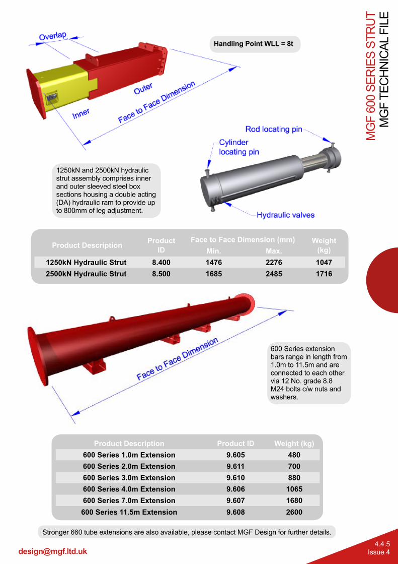
Fabricated from API grade X70 610x12.5 hollow circular steel section, and S355 grade 660x20/25 CHS, the extensions are quickly assembled into the required strut lengths using circular flanged plates c/w bolt, nut and washer assemblies. Final length adjustment is provided by a double acting hydraulic ram providing up to 800mm of stroke. Once located at the correct line and level the struts are pre-loaded (or tightened) against the faces to be supported using a hydraulic pump on the ram. Pre-loading of the legs ensures the strut cannot slip, takes up any slack or hogging in the system and minimises the extent of potential ground movements. Handling points are provided at regular intervals on each leg to assist assembly / removal.
MGF can supply the systems with a full range of suitable handling chains, hydraulic pump installation kits (including bio-degradable shoring fluid and hydraulic hoses) and confined spaces regime equipment.
Manufactured and designed in accordance with BS EN 14653:2005 PARTS 1 and 2 Manually operated Shoring Systems for Groundwork Support and BS 5975 (2008) Code of Practice for Temporary Works Procedures and the Permissible Stress Design of Falsework.
Product Notes1. Strut systems are very heavy and should only be assembled, installed and removed by competent persons
in accordance with a site specific detailed design & installation sequence and MGF installation guidelines.2. Installation is normally carried out by assembling the complete strut and then lowering into place (subject
to crane / excavator capacity). Struts are normally long and unbalanced (due to the weight of ram/jack unit) and great care must be taken in preparing the lift / maintaining lift angle (tag lines strongly recommended). On the ram assembly max pre-load pressure of 100Bar (1500psi) must not be exceeded unless design states otherwise.
3. Additional restraining chains or support brackets are normally provided to the brace at intermediate strut locations to carry the additional strut weight.
4. Ensure struts are fully pre-loaded or tightened, end fixings fully packed, all hydraulic ram isolation valves are closed prior to releasing strut from lifting chains and commencing works. When assembling on site ensure that all pins and retaining clips are in place and secured and all flange plate bolts are installed and fully tightened / torqued with a minimum two threads visible beyond the nut. Any gaps in bearing plates must be securely packed using grout prior to final pre-loading of the hydraulic rams.
5. Individual components should be visually inspected for damage, excessive deflection, loss of ram pressure or loose locking collars prior to entering the excavation.
6. Safe access/egress, edge protection (for personnel) and barrier protection (for plant) should always be considered.
7. Prior to removal of systems the complete weight of the strut must be independently supported. Once this is accomplished the hydraulic rams (or struts) must be released and retracted to avoid the need for excessive extraction forces.
8. When installing struts at angles great care must be taken to ensure that the angles match the design, all shear stops are in place and all elements are supported/packed and capable of transmitting loads effectively. On large unsupported spans the pre-load must be applied prior to removing vertical support to minimise sagging.
Tel. 0808 1153 122
MG
F TE
CH
NIC
AL F
ILE
MG
F 60
0 SE
RIE
S ST
RU
T
4.4.2Issue 4
MGF 600 Series
Handling PointsWLL = 12.0t
Strut assemblies are lifted and handled by attaching MGF lifting chains to the handling/restraining
points as shown.Assemblies can also be handled
using a fork lift on the pockets on the underside of the extensions.
Strut Flange Connection Detail600 Series Struts and Extensions are connected to each other via a flange plate (Φ850x30mm) using
12 No. grade 8.8 M24 bolts c/w nuts and washers (recommended min.
torque 400Nm).
Transition Flange Connection Detail
The transition adaptor is connected to the hydraulic strut or 400 series extension via a square flange plate
(520x520x30mm) and connects to 600 Series via a circular
end plate(Φ850x30mm) both connections using 12 No. grade 8.8
M24 bolts c/w nuts and washers (recommended min. torque 400Nm).
1250kN and 2500kN hydraulic strut assembly comprises inner and outer sleeved steel box sections housing a double acting (DA) hydraulic ram to provide up to 800mm of leg adjustment.
Handling Point WLL = 8t
Stronger 660 tube extensions are also available, please contact MGF Design for further details.
Tel. 0808 1153 122
MG
F TE
CH
NIC
AL F
ILE
MG
F 60
0 SE
RIE
S ST
RU
T
4.4.6Issue 4
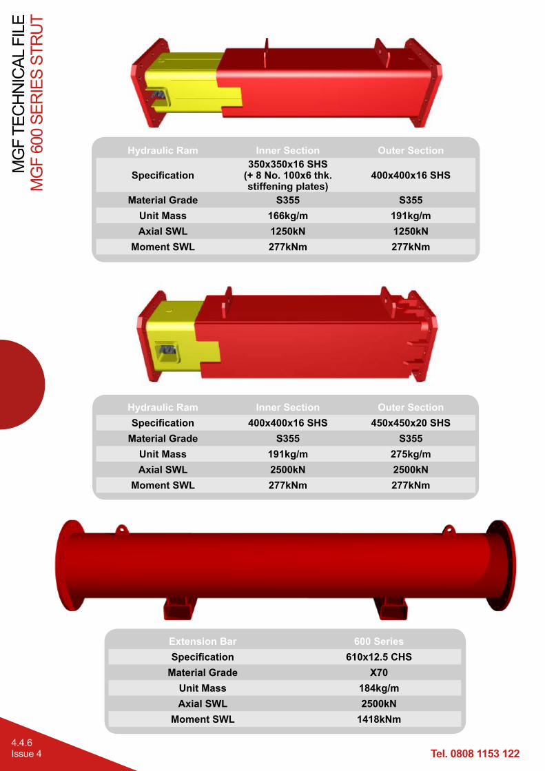
Hydraulic Ram Inner Section Outer Section
Specification350x350x16 SHS
(+ 8 No. 100x6 thk. stiffening plates)
400x400x16 SHS
Material Grade S355 S355Unit Mass 166kg/m 191kg/mAxial SWL 1250kN 1250kN
The motorised pumps are used to extend and retract the 600 Series double acting hydraulic rams. The pumps contain neat bio-degradable Houghto Safe SF25 shoring fluid. Maximum recommended installation pressure 1500 psi (100 Bar).MGF supply 2 different types of motorised pump for 600 Series, electric and diesel.
Shoring fluid is pumped into the full bore side of the piston through the male quick release valve (QRV) to extend the ram.At the same time fluid from the return side of the piston is returned to the pump via the female QRV. Retraction is a reverse of extension.Ensure isolation valve is closed to maintain pre-load pressure and before release/connection of QRV’s.
Tel. 0808 1153 122
MG
F TE
CH
NIC
AL F
ILE
MG
F 60
0 SE
RIE
S ST
RU
T
4.4.8Issue 4
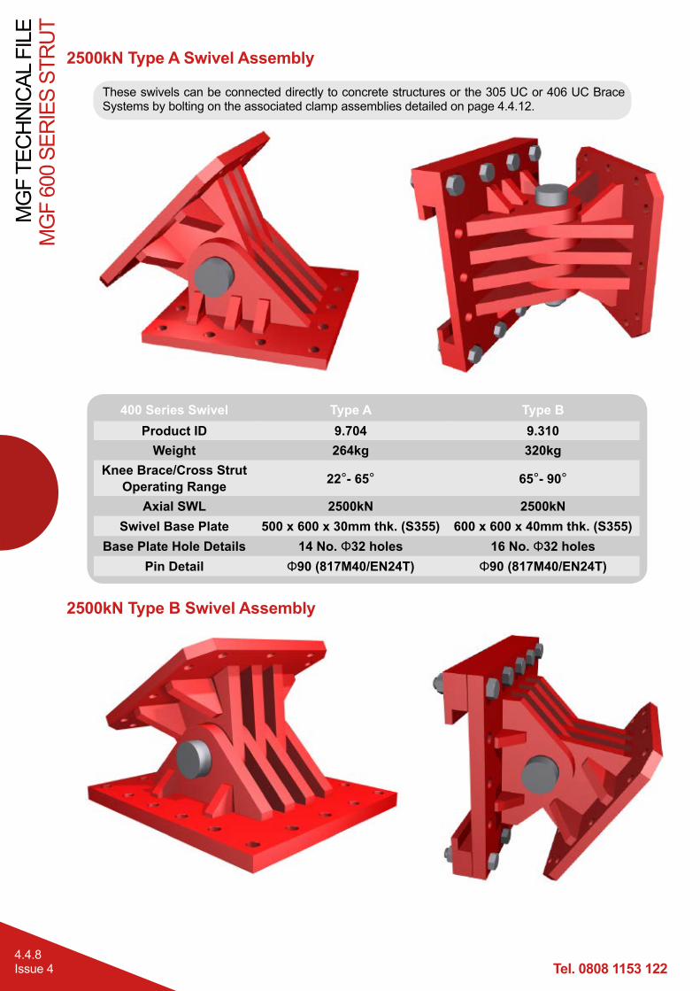
2500kN Type A Swivel Assembly
400 Series Swivel Type A Type BProduct ID 9.704 9.310
Weight 264kg 320kgKnee Brace/Cross Strut
Operating Range 22°- 65° 65°- 90°
Axial SWL 2500kN 2500kNSwivel Base Plate 500 x 600 x 30mm thk. (S355) 600 x 600 x 40mm thk. (S355)
These swivels can be connected directly to concrete structures or the 305 UC or 406 UC Brace Systems by bolting on the associated clamp assemblies detailed on page 4.4.12.
Moment SWL 1125kNm 396kNmJoint Moment SWL 396/1125 kNm 277/396 kNm
Tel. 0808 1153 122
MG
F TE
CH
NIC
AL F
ILE
MG
F 60
0 SE
RIE
S ST
RU
T
4.4.10Issue 4
600 Series Recommended Extension Combinations
N.B Single 0.25 or 0.5m 400 Series extensions should be added to these combinations for intermediate dimensions. The strut assemblies are shown at mid-stroke, so each length can vary by up to 400mm in either direction. Individual 7m pieces can be exchanged for a 3m and 4m. Additional compatible extensions are available (660 diameter / 1000 Series). Contact MGF Design department for details.
The above strut combinations use the 600 Series Extensions (610 tube).
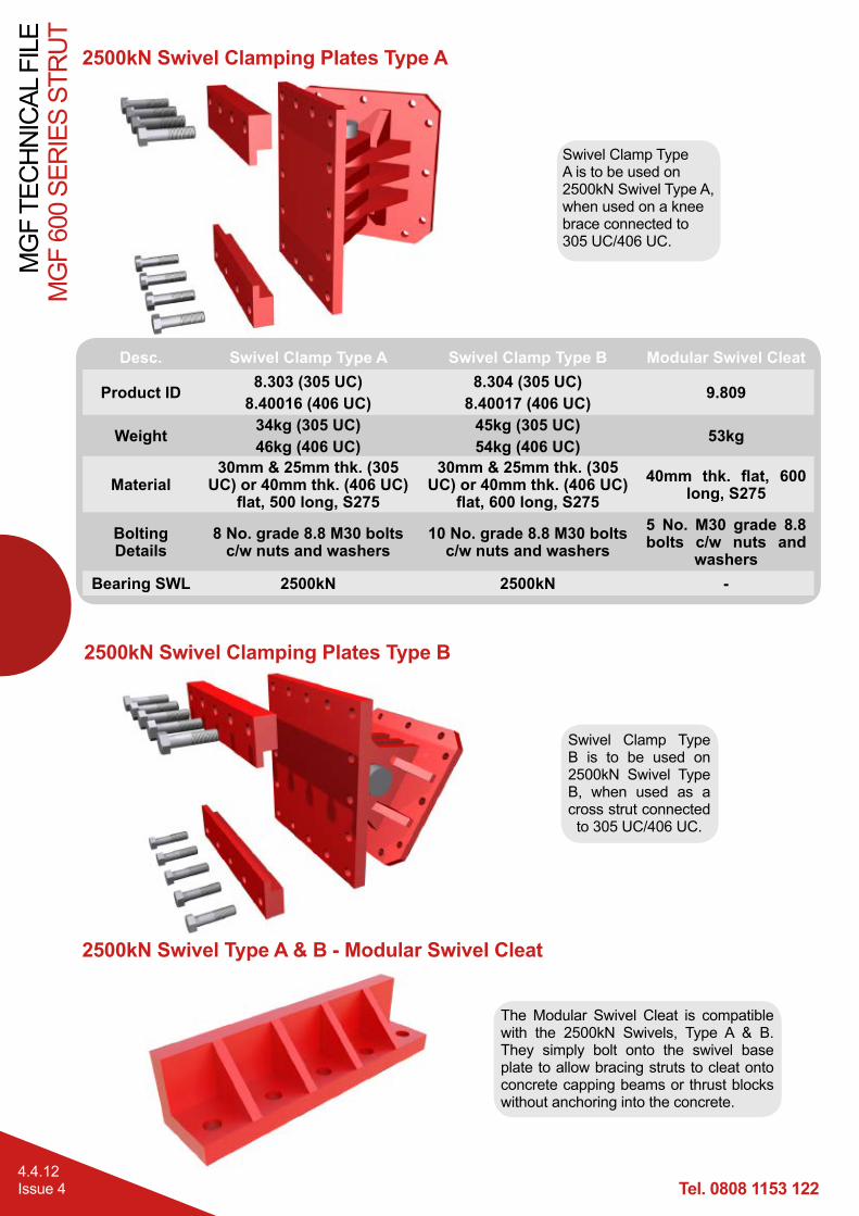
Swivel Clamp Type A is to be used on 2500kN Swivel Type A, when used on a knee brace connected to 305 UC/406 UC.
Swivel Clamp Type B is to be used on 2500kN Swivel Type B, when used as a cross strut connected to 305 UC/406 UC.
Desc. Swivel Clamp Type A Swivel Clamp Type B Modular Swivel Cleat
Product ID 8.303 (305 UC)8.40016 (406 UC)
8.304 (305 UC)8.40017 (406 UC) 9.809
Weight 34kg (305 UC)46kg (406 UC)
45kg (305 UC)54kg (406 UC) 53kg
Material30mm & 25mm thk. (305
UC) or 40mm thk. (406 UC) flat, 500 long, S275
30mm & 25mm thk. (305 UC) or 40mm thk. (406 UC)
flat, 600 long, S27540mm thk. flat, 600
long, S275
Bolting Details
8 No. grade 8.8 M30 bolts c/w nuts and washers
10 No. grade 8.8 M30 bolts c/w nuts and washers
5 No. M30 grade 8.8 bolts c/w nuts and
washersBearing SWL 2500kN 2500kN -
2500kN Swivel Clamping Plates Type B
2500kN Swivel Type A & B - Modular Swivel Cleat
The Modular Swivel Cleat is compatible with the 2500kN Swivels, Type A & B. They simply bolt onto the swivel base plate to allow bracing struts to cleat onto concrete capping beams or thrust blocks without anchoring into the concrete.