26
MICRO GUARD RCI 510 Telescopic Boom Cranes Upgrade Installation and Setup Manual

MICRO GUARD RCI 510 Telescopic Boom Cranes
Upgrade Installation and Setup Manual


SkyAzúl, Equipment Solutions www.skyazul.com 301-371-6126
NOTICE SkyAzúl makes no warranty of any kind with regard to this material, including, but not limited to, the implied warranties of merchantability and/or its fitness for a particular purpose.
SkyAzúl will not be liable for errors contained in this manual or for incidental or consequential damages in connection with the furnishing, performance, or use of this manual. This document contains proprietary information, which is protected by copyright, and all rights are reserved.
No part of this document may be photocopied, reproduced, or translated to another language without the prior written consent of SkyAzúl.
SkyAzúl reserves proprietary rights to all drawings, photos and the data contained therein. The drawings, photos and data are confidential and cannot be used or reproduced without the written consent of SkyAzúl. The drawings and/or photos are subject to technical modification without prior notice.
All information in this document is subject to change without notice.
SkyAzúl, Inc. 16 Walnut Street Middletown, MD 21769 Fax 301-371-0029 [email protected]

SkyAzúl, Equipment Solutions www.skyazul.com 301-371-6126
Table of Contents
1 Installation ............................................................................................................................................ 1
Introduction .............................................................................................................................................. 1
1.1 System Information ....................................................................................................................... 1
1.2 Upgrade Parts: .............................................................................................................................. 2
1.2.1 A450769 Computer Assembly ............................................................................................... 2
1.2.2 A450251 RCI 510 Display ...................................................................................................... 2
1.2.3 A240690 Reeling Drum ......................................................................................................... 3
1.3 Computer Wiring ........................................................................................................................... 4
1.4 Units with Swing Switches ............................................................................................................ 6
1.5 Removal and Installation .............................................................................................................. 7
2 Operation .............................................................................................................................................. 9
Outline of Operation ................................................................................................................................. 9
2.1 System Setup ............................................................................................................................... 11
2.1.1 Required Tools .................................................................................................................... 11
2.1.2 Crane Configuration ............................................................................................................ 11
2.1.3 Entering Setup Mode .......................................................................................................... 12
2.1.4 Checking for Error Codes .................................................................................................... 13
2.1.5 Zero for Extension ............................................................................................................... 13
2.1.6 Setting Zero for Boom Angle ............................................................................................... 14
2.1.7 Adjusting the displayed “0” to match the actual “0” on the leveling tool. ......................... 15
2.1.8 Entering a Span ................................................................................................................... 16
2.1.9 The Entry Screen ................................................................................................................. 17
2.1.10 Setting the Rope Limit Option ............................................................................................. 18


MICRO GUARD® RCI 510 – Upgrade Installation and Setup Manual 1
SkyAzúl, Equipment Solutions www.skyazul.com 301-371-6126
1 Installation
Introduction
The MicroGuard MG510 replaces the previous Terex MG404, 414, and RCI 500 system currently using the obsolete MG400 computer. This section will cover the necessary installation instructions for the MicroGuard 510 using the new 500 series computer. Please read the Operator’s Manual carefully before operating the system. The system installer must be knowledgeable in safety guidelines, crane capacity information, and the crane manufacturer’s specifications. For questions about Installation, please contact Technical Support: SkyAzúl, Equipment Solutions 200 W. Main Street, Suite, 2A Middletown, MD 21769 Fax 301-371-0029 [email protected]
1.1 SystemInformation
When installing the new computer and display, Greer Company recommends the existing rectangular shaped reeling drum be replaced with our current production reeling drum, A240690. The rectangular shaped reeling drum is obsolete. There is no longer field support for this product. Installing the new reeling drum will ensure field support and parts support in the future. The A240690 reeling drum is equipped with mounting brackets and electrical fittings to be a direct replacement. The new computer uses Flash RAM technology for loading the Duty Files. If known at the time of purchase, the proper Duty File will be loaded on your computer before being shipped. Kit K758743 is available for preparing the new flash-style computer for use. The kit contains a programming cable, a CD with the necessary software, and a PDF copy of the instruction manual to allow the installer to load the correct Duty File on the computer.
MICRO GUARD® RCI 510 – Upgrade Installation and Setup Manual 2
SkyAzúl, Equipment Solutions www.skyazul.com 301-371-6126
1.2 UpgradeParts:
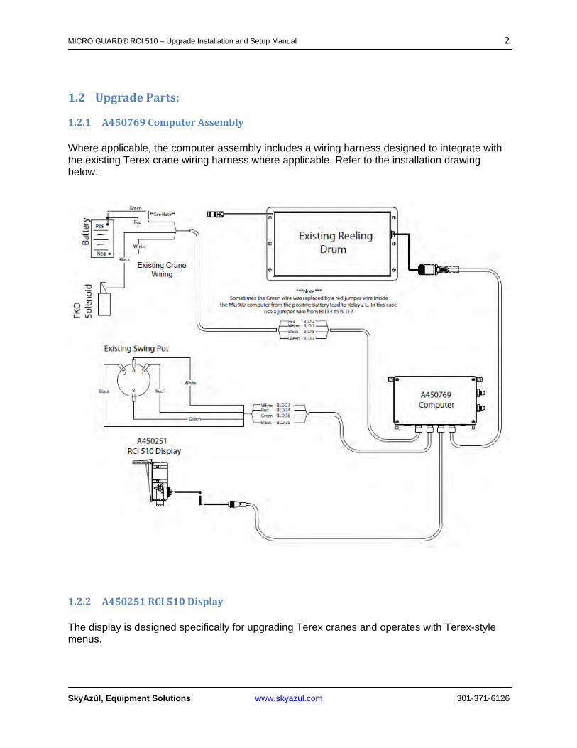
1.2.1 A450769ComputerAssembly Where applicable, the computer assembly includes a wiring harness designed to integrate with the existing Terex crane wiring harness where applicable. Refer to the installation drawing below.
1.2.2 A450251RCI510Display The display is designed specifically for upgrading Terex cranes and operates with Terex-style menus.
MICRO GUARD® RCI 510 – Upgrade Installation and Setup Manual 3
SkyAzúl, Equipment Solutions www.skyazul.com 301-371-6126
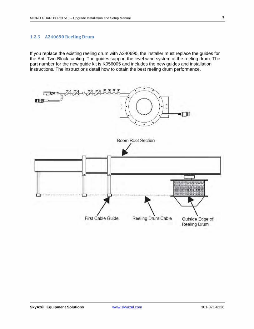
1.2.3 A240690ReelingDrum
If you replace the existing reeling drum with A240690, the installer must replace the guides for the Anti-Two-Block cabling. The guides support the level wind system of the reeling drum. The part number for the new guide kit is K056005 and includes the new guides and installation instructions. The instructions detail how to obtain the best reeling drum performance.
MICRO GUARD® RCI 510 – Upgrade Installation and Setup Manual 4
SkyAzúl, Equipment Solutions www.skyazul.com 301-371-6126
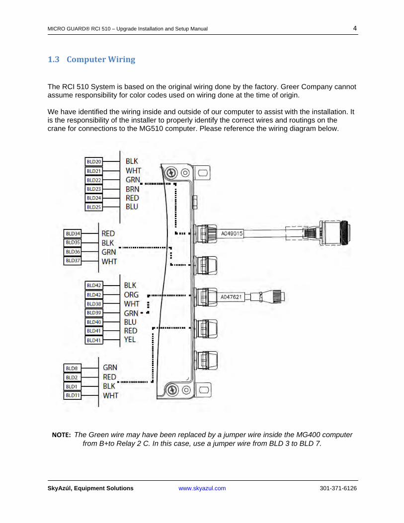
1.3 ComputerWiring
The RCI 510 System is based on the original wiring done by the factory. Greer Company cannot assume responsibility for color codes used on wiring done at the time of origin. We have identified the wiring inside and outside of our computer to assist with the installation. It is the responsibility of the installer to properly identify the correct wires and routings on the crane for connections to the MG510 computer. Please reference the wiring diagram below.
NOTE: The Green wire may have been replaced by a jumper wire inside the MG400 computer
from B+to Relay 2 C. In this case, use a jumper wire from BLD 3 to BLD 7.

MICRO GUARD® RCI 510 – Upgrade Installation and Setup Manual 5
SkyAzúl, Equipment Solutions www.skyazul.com 301-371-6126
Computer Wiring Connections Connection Connection Work Instruction A450663 A450763
JP3-1Battery 0V BLD 1 Battery -VE Connect to Frame Ground System Power JP3-2 BLD 2 Battery +VE Connect to Crane Power 12V - 36V
(Fused at 10 Amp power source)JP 5-1 Relay Power Feed BLD 7 Relay Power
Feed Power for Function Kickout
JP 5-2 Solenoid Output BLD 8 Solenoid Output Power to Function Kick Out Solenoids on Crane
Connection Connection Work Instruction A450663 A450763
JP 12-1 (Data "A") BLD 38 (Data "A") Display Communication connection JP 12-2 (Data "B") BLD 39 (Data "B") Display Communication connection JP 12-3 Reset BLD 40 Reset Reset line…..Usually Blue JP 12-4 Display Power BLD 41 Power 12V Power for Display JP 12-5 BLD 42 Ground Display Ground Wire
Connection Connection Work Instruction A450663 A450763
JP9-1 BLD 26 Digital Input (12V) JP9-2 BLD 27 Digital Input (12V) JP9-3 BLD 28 Digital Input (12V) JP9-4 BLD 29 Digital Input (12V) BLD 30 12V Power Supply
Connection Connection Work Instruction A450663 A450763
JP11-1 BLD 34 Drive Voltage for Swing Pot JP11-2 BLD 35 Ground Signal for Swing Pot JP11-3 BLD 36 Communication Connection JP11-4 BLD 37 Communication Connection
Connection Connection Work Instruction A450663 A450763
JP8-1 BLD 20 Monitored Voltage Signal Anti 2 BlockJP8-2 BLD 21 Analog Signal from Ext. to ComputerJP8-3 BLD 22 Analog Signal from Angle to ComputerJP8-4 BLD 23 Monitored Voltage Signal Anti 2 BlockJP8-5 BLD 24 Drive Voltage for Swing Pot JP8-6 BLD 25 Internal Ground (Drive Voltage)
MICRO GUARD® RCI 510 – Upgrade Installation and Setup Manual 6
SkyAzúl, Equipment Solutions www.skyazul.com 301-371-6126
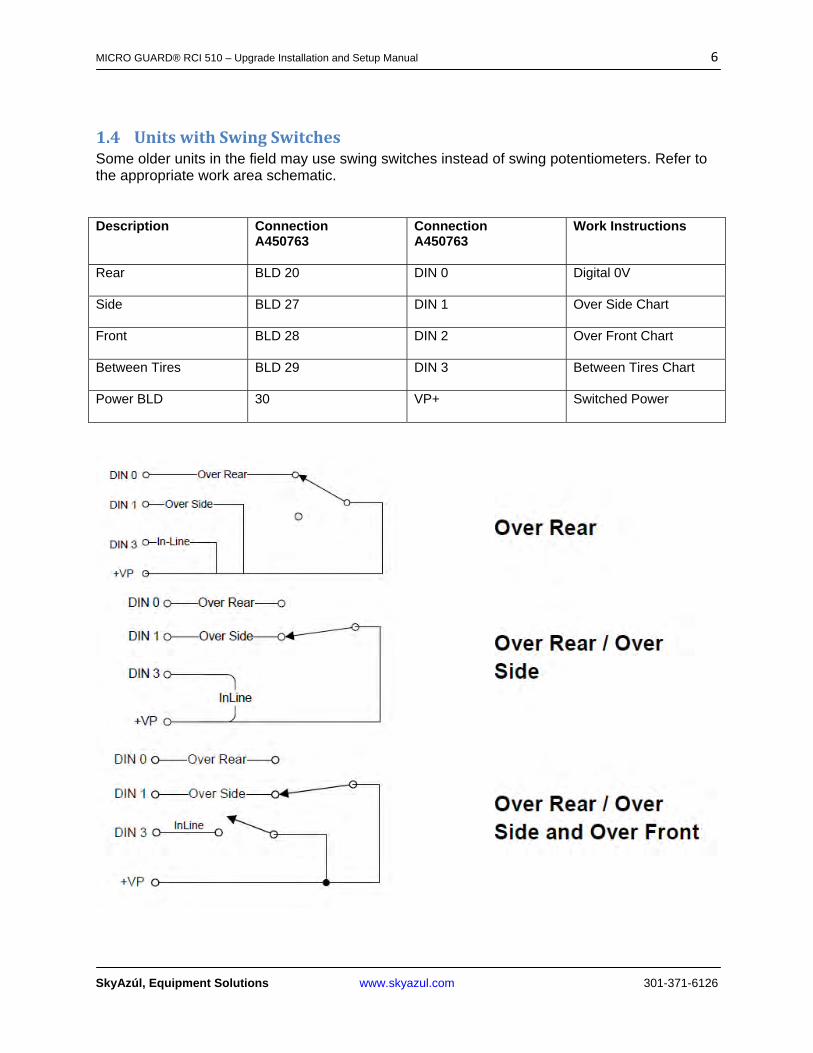
1.4 UnitswithSwingSwitchesSome older units in the field may use swing switches instead of swing potentiometers. Refer to the appropriate work area schematic.
Description Connection A450763
Connection A450763
Work Instructions
Rear BLD 20 DIN 0 Digital 0V
Side BLD 27 DIN 1 Over Side Chart
Front BLD 28 DIN 2 Over Front Chart
Between Tires BLD 29 DIN 3 Between Tires Chart
Power BLD 30 VP+ Switched Power
MICRO GUARD® RCI 510 – Upgrade Installation and Setup Manual 7
SkyAzúl, Equipment Solutions www.skyazul.com 301-371-6126
1.5 RemovalandInstallation1. Place the crane in rigging mode and raise the boom. This will allow access to the hose
fittings and wiring harness connections.
NOTE: Leave the power and FKO cables connected to allow movement of the boom during the removal and installation process.
2. Disconnect the reeling drum cable. 3. Disconnect the swing sensor. 4. Remove the display. 5. Remove the display cable. 6. Unscrew the four bolts and remove the old computer from its mounting place. Place the
computer on the deck. NOTE: Do not disconnect the power and FKO cables. 7. The new computer is smaller than the existing one. Mount the new computer using one
of the existing bolt holes. Use the new computer as a template to drill three new mounting holes.
8. Screw in the remaining bolts. Ensure the computer is securely attached. 9. Lower the boom completely. Remove the exisiting pressure hoses from the old
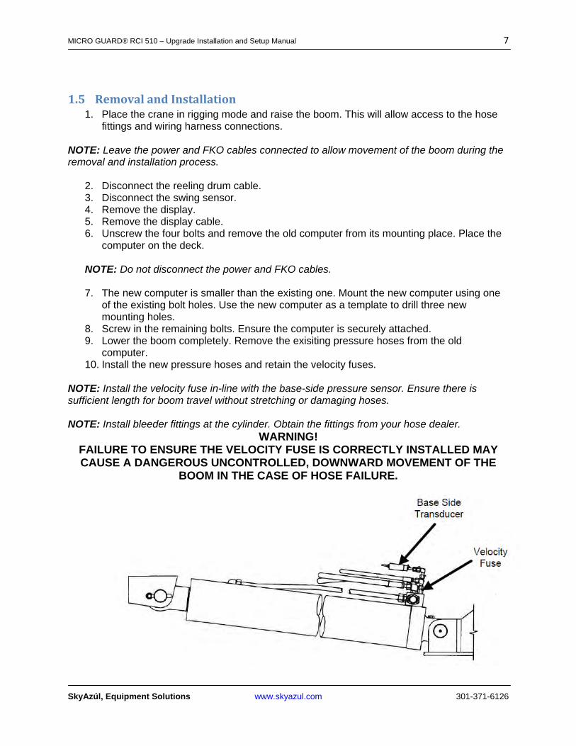
computer. 10. Install the new pressure hoses and retain the velocity fuses.
NOTE: Install the velocity fuse in-line with the base-side pressure sensor. Ensure there is sufficient length for boom travel without stretching or damaging hoses. NOTE: Install bleeder fittings at the cylinder. Obtain the fittings from your hose dealer.
WARNING! FAILURE TO ENSURE THE VELOCITY FUSE IS CORRECTLY INSTALLED MAY CAUSE A DANGEROUS UNCONTROLLED, DOWNWARD MOVEMENT OF THE
BOOM IN THE CASE OF HOSE FAILURE.

MICRO GUARD® RCI 510 – Upgrade Installation and Setup Manual 8
SkyAzúl, Equipment Solutions www.skyazul.com 301-371-6126
11. Connect the new pressure hoses to the new computer. 12. Raise the boom. 13. If using the rectangular reeling drum, disconnect the reeling drum cable and remove.
The new computer is wired with a new cable and only needs to be attached to the reeling drum.
14. Install the display. 15. Install the display cable. 16. Install the power and FKO cables to the new computer. 17. Slowly elevate the boom to its maximum angle to ensure the pressure hoses and
electrical cables are properly routed.
WARNING! ENSURE THE PRESSURE HOSES AND ELECTRICAL CABLES ARE ROUTED PROPERLY. IF MISROUTED, WHEN THE BOOM IS RAISED THE 1ST TIME THE
HOSES/CABLES CAN BE DAMAGED OR DESTROYED.
MICRO GUARD® RCI 510 – Upgrade Installation and Setup Manual 9
SkyAzúl, Equipment Solutions www.skyazul.com 301-371-6126
2 Operation
OutlineofOperation
SYSTEM COMPONENTS
Microguard® RCI 510 Display Unit Microguard® RCI 510 Computer Unit Pressure Transducers Extension Reel with length and angle sensors Anti 2-Block (ATB) switches Cables Installation/Operator Manuals
The MICROGUARD® RCI 510 System continuously monitors the load and warns of an approach to an overload or Two-Block condition. Crane functions are monitored by means of high accuracy sensors. The system continuously compares the load suspended below the boom head with the crane capacity chart stored in the computer memory. At approach to overload, the system warns by means of audible and visual alarms. The system can be configured to cause function kick-out by sending a signal to function disconnect solenoids. DISPLAY The Microguard® RCI 510 System continuously displays:
Rated Load Actual Load Bar Graph showing Percentage of Rated Load Radius of the Load Boom Angle Main Boom Length Working Area Crane Configuration
On-screen messages provide visual warnings of conditions that occur during operation of the system. BOOM ANGLE SENSOR The Boom Angle Sensor is a magnetically dampened potentiometer that measures the angle of the boom.
EXTENSION SENSOR The Extension Sensor measures the length of the boom. It is located inside the Extension Reel cover.
PRESSURE TRANSDUCERS The pressure transducers measure pressure in the boom hoist cylinder. the signal is then processed to provide a continuous display of the total load suspended below the point of lift.

MICRO GUARD® RCI 510 – Upgrade Installation and Setup Manual 10
SkyAzúl, Equipment Solutions www.skyazul.com 301-371-6126
ANTI TWO BLOCK (A2B) The ®Anti Two Block system provides protection by preventing pulling the load block into the head of the boom and causing structural damage to, or breaking the lifting cable. The system, when activated, will prevent movement of any function that could further cause the condition to become unsafe. (Boom Down, Winch Up, Boom Out.)
OPERATOR SETTABLE ALARMS Operator Settable Alarms provide work area protection zones, warnings for various job site conditions, and alarms for overhead obstructions.
These alarms include: Max and Min. Boom Angle Max and Min. Boom Extension and Boom Tip Height. Work Area and Exclusion Zone Alarms.
Note: Operator Alarms do not cause function lock out to occur.

MICRO GUARD® RCI 510 – Upgrade Installation and Setup Manual 11
SkyAzúl, Equipment Solutions www.skyazul.com 301-371-6126
2.1 SystemSetup The Microguard® RCI 510 system contains a setup calibration mode that operates through the system display console. The setup mode provides a means of ensuring that the system sensors are correctly positioned and adjusted following system installation or parts replacement. This procedure assumes that installation of system components, cabling, and hydraulic connections have been successfully completed and checked. The setup procedure involves only the sensors mounted within the extension reel on the side of the boom. It is important that each step of this procedure is properly followed for the system to accurately provide load, rated capacity, warnings, and kick out functions.
2.1.1 RequiredToolsFor Setup: Phillips Screwdrivers, Bubble Level – Accurate to 0.1° at level
For Testing: Inclinometer – accurate to 0.2°, Mearuring tape (100 ft) – fiber‐type with tenths of feet
2.1.2 CraneConfigurationBefore starting the system setup, position the crane on firm and level ground with the outriggers properly extended and set. It is recommended that the crane be configured with no stowed or erected jib (bare boom) and reeved with a single part-of-line.
WARNING! At all times, observe safe practices. Make sure that crane capacity limitations are
understood, and that the crane capacity plate is followed. Do not exceed manufacturer's specified
lifting limitations.
MICRO GUARD® RCI 510 – Upgrade Installation and Setup Manual 12
SkyAzúl, Equipment Solutions www.skyazul.com 301-371-6126
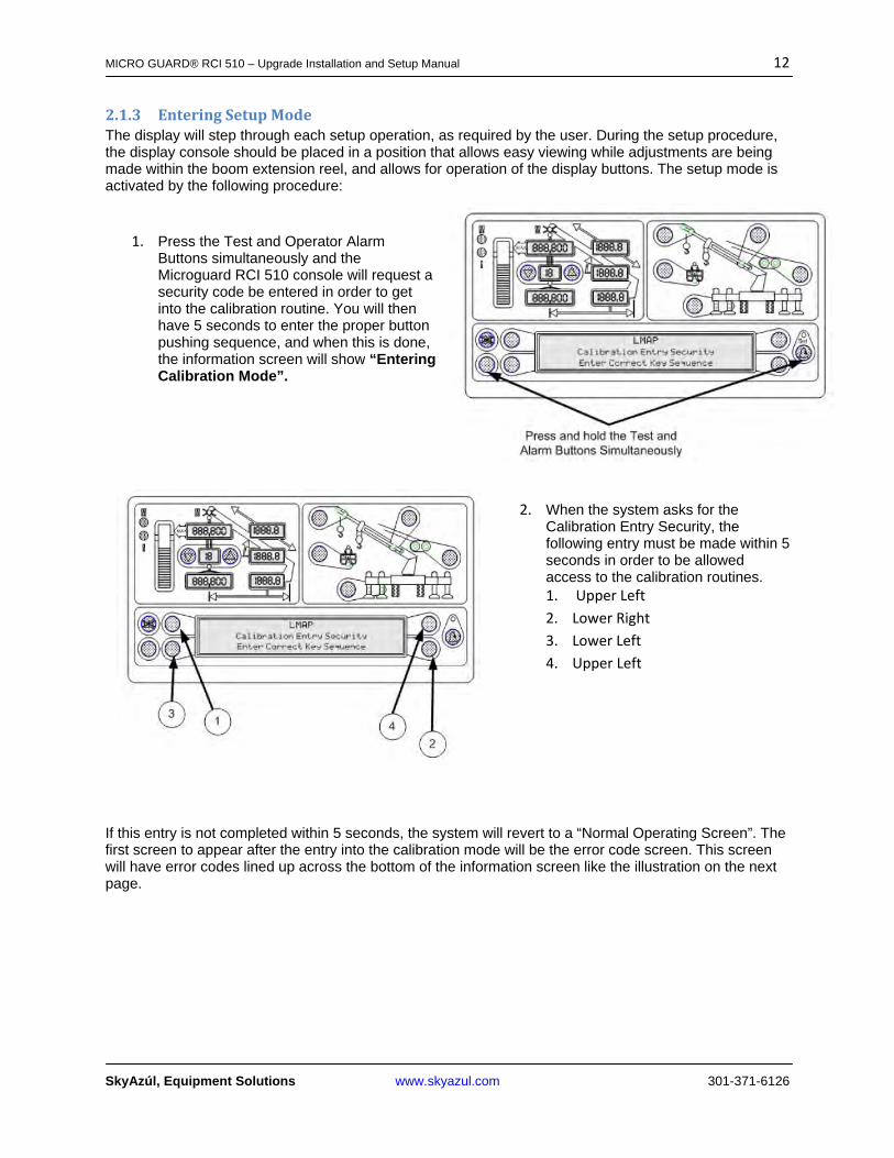
2.1.3 EnteringSetupModeThe display will step through each setup operation, as required by the user. During the setup procedure, the display console should be placed in a position that allows easy viewing while adjustments are being made within the boom extension reel, and allows for operation of the display buttons. The setup mode is activated by the following procedure:
1. Press the Test and Operator Alarm Buttons simultaneously and the Microguard RCI 510 console will request a security code be entered in order to get into the calibration routine. You will then have 5 seconds to enter the proper button pushing sequence, and when this is done, the information screen will show “Entering Calibration Mode”.
2. When the system asks for the Calibration Entry Security, the following entry must be made within 5 seconds in order to be allowed access to the calibration routines. 1. Upper Left
2. Lower Right
3. Lower Left
4. Upper Left
If this entry is not completed within 5 seconds, the system will revert to a “Normal Operating Screen”. The first screen to appear after the entry into the calibration mode will be the error code screen. This screen will have error codes lined up across the bottom of the information screen like the illustration on the next page.
MICRO GUARD® RCI 510 – Upgrade Installation and Setup Manual 13
SkyAzúl, Equipment Solutions www.skyazul.com 301-371-6126
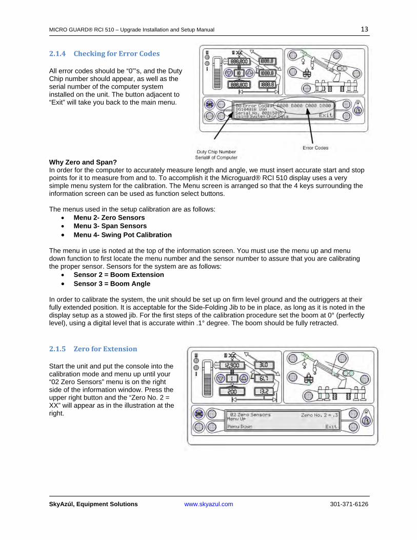
2.1.4 CheckingforErrorCodes All error codes should be “0”’s, and the Duty Chip number should appear, as well as the serial number of the computer system installed on the unit. The button adjacent to “Exit” will take you back to the main menu.
Why Zero and Span? In order for the computer to accurately measure length and angle, we must insert accurate start and stop points for it to measure from and to. To accomplish it the Microguard® RCI 510 display uses a very simple menu system for the calibration. The Menu screen is arranged so that the 4 keys surrounding the information screen can be used as function select buttons. The menus used in the setup calibration are as follows:
Menu 2- Zero Sensors Menu 3- Span Sensors Menu 4- Swing Pot Calibration
The menu in use is noted at the top of the information screen. You must use the menu up and menu down function to first locate the menu number and the sensor number to assure that you are calibrating the proper sensor. Sensors for the system are as follows:
Sensor 2 = Boom Extension Sensor 3 = Boom Angle
In order to calibrate the system, the unit should be set up on firm level ground and the outriggers at their fully extended position. It is acceptable for the Side-Folding Jib to be in place, as long as it is noted in the display setup as a stowed jib. For the first steps of the calibration procedure set the boom at 0° (perfectly level), using a digital level that is accurate within .1° degree. The boom should be fully retracted.
2.1.5 ZeroforExtension Start the unit and put the console into the calibration mode and menu up until your “02 Zero Sensors” menu is on the right side of the information window. Press the upper right button and the “Zero No. 2 = XX” will appear as in the illustration at the right.
MICRO GUARD® RCI 510 – Upgrade Installation and Setup Manual 14
SkyAzúl, Equipment Solutions www.skyazul.com 301-371-6126
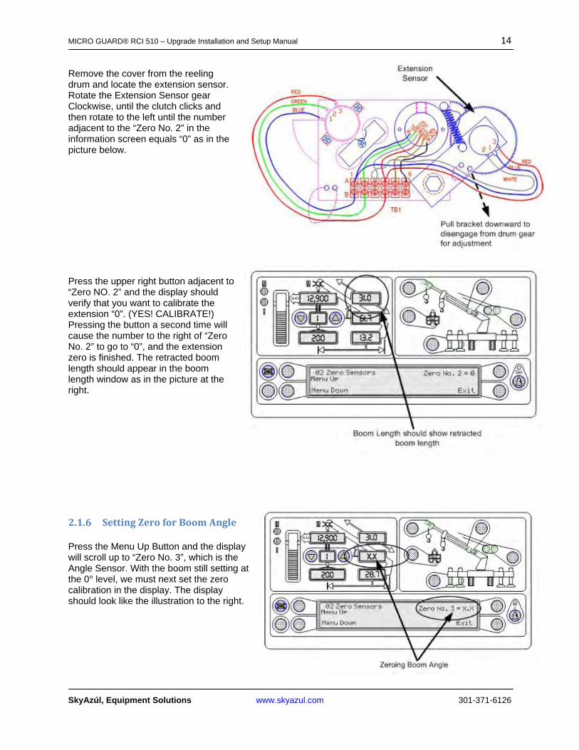
Remove the cover from the reeling drum and locate the extension sensor. Rotate the Extension Sensor gear Clockwise, until the clutch clicks and then rotate to the left until the number adjacent to the “Zero No. 2” in the information screen equals “0” as in the picture below.
Press the upper right button adjacent to “Zero NO. 2” and the display should verify that you want to calibrate the extension “0”. (YES! CALIBRATE!) Pressing the button a second time will cause the number to the right of “Zero No. 2” to go to “0”, and the extension zero is finished. The retracted boom length should appear in the boom length window as in the picture at the right.
2.1.6 SettingZeroforBoomAngle Press the Menu Up Button and the display will scroll up to “Zero No. 3”, which is the Angle Sensor. With the boom still setting at the 0° level, we must next set the zero calibration in the display. The display should look like the illustration to the right.
MICRO GUARD® RCI 510 – Upgrade Installation and Setup Manual 15
SkyAzúl, Equipment Solutions www.skyazul.com 301-371-6126
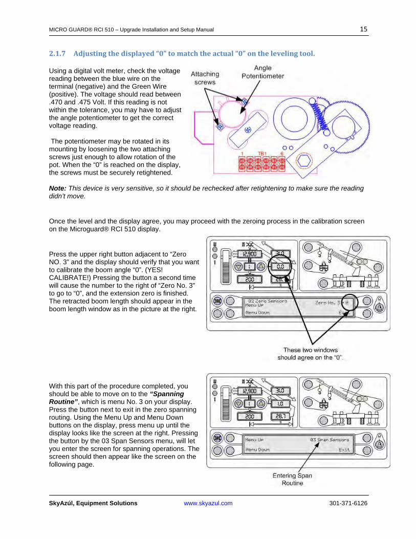
2.1.7 Adjustingthedisplayed“0”tomatchtheactual“0”onthelevelingtool. Using a digital volt meter, check the voltage reading between the blue wire on the terminal (negative) and the Green Wire (positive). The voltage should read between .470 and .475 Volt. If this reading is not within the tolerance, you may have to adjust the angle potentiometer to get the correct voltage reading. The potentiometer may be rotated in its mounting by loosening the two attaching screws just enough to allow rotation of the pot. When the “0” is reached on the display, the screws must be securely retightened. Note: This device is very sensitive, so it should be rechecked after retightening to make sure the reading didn’t move.
Once the level and the display agree, you may proceed with the zeroing process in the calibration screen on the Microguard® RCI 510 display.
Press the upper right button adjacent to “Zero NO. 3” and the display should verify that you want to calibrate the boom angle “0”. (YES! CALIBRATE!) Pressing the button a second time will cause the number to the right of “Zero No. 3” to go to “0”, and the extension zero is finished. The retracted boom length should appear in the boom length window as in the picture at the right.
With this part of the procedure completed, you should be able to move on to the “Spanning Routine”, which is menu No. 3 on your display. Press the button next to exit in the zero spanning routing. Using the Menu Up and Menu Down buttons on the display, press menu up until the display looks like the screen at the right. Pressing the button by the 03 Span Sensors menu, will let you enter the screen for spanning operations. The screen should then appear like the screen on the following page.
MICRO GUARD® RCI 510 – Upgrade Installation and Setup Manual 16
SkyAzúl, Equipment Solutions www.skyazul.com 301-371-6126
The functions of spanning the boom, includes actions that necessitate full boom extension, so you must maneuver the boom into a boom angle that will allows you to safely extend the boom to the fullest length. (Usually above 65°) You must take precautions to avoid overhead power lines and any other obstructions that may exist.
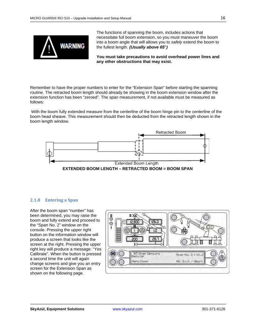
Remember to have the proper numbers to enter for the “Extension Span” before starting the spanning routine. The retracted boom length should already be showing in the boom extension window after the extension function has been “zeroed”. The span measurement, if not available must be measured as follows: With the boom fully extended measure from the centerline of the boom hinge pin to the centerline of the boom head sheave. This measurement should then be deducted from the retracted length shown in the boom length window.
EXTENDED BOOM LENGTH – RETRACTED BOOM = BOOM SPAN
2.1.8 EnteringaSpan After the boom span “number” has been determined, you may raise the boom and fully extend and proceed to the “Span No. 2” window on the console. Pressing the upper right button on the information window will produce a screen that looks like the screen at the right. Pressing the upper right key will produce a message: “Yes Calibrate”. When the button is pressed a second time the unit will again change screens and give you an entry screen for the Extension Span as shown on the following page.
MICRO GUARD® RCI 510 – Upgrade Installation and Setup Manual 17
SkyAzúl, Equipment Solutions www.skyazul.com 301-371-6126
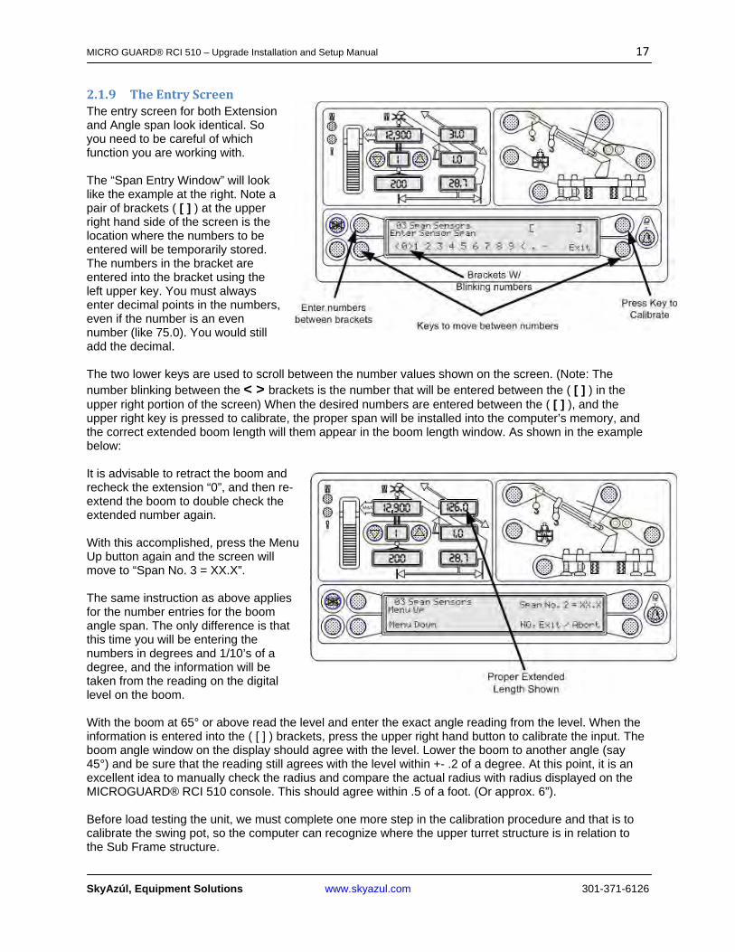
2.1.9 TheEntryScreenThe entry screen for both Extension and Angle span look identical. So you need to be careful of which function you are working with. The “Span Entry Window” will look like the example at the right. Note a pair of brackets ( [ ] ) at the upper right hand side of the screen is the location where the numbers to be entered will be temporarily stored. The numbers in the bracket are entered into the bracket using the left upper key. You must always enter decimal points in the numbers, even if the number is an even number (like 75.0). You would still add the decimal. The two lower keys are used to scroll between the number values shown on the screen. (Note: The number blinking between the < > brackets is the number that will be entered between the ( [ ] ) in the upper right portion of the screen) When the desired numbers are entered between the ( [ ] ), and the upper right key is pressed to calibrate, the proper span will be installed into the computer’s memory, and the correct extended boom length will them appear in the boom length window. As shown in the example below: It is advisable to retract the boom and recheck the extension “0”, and then re-extend the boom to double check the extended number again. With this accomplished, press the Menu Up button again and the screen will move to “Span No. 3 = XX.X”. The same instruction as above applies for the number entries for the boom angle span. The only difference is that this time you will be entering the numbers in degrees and 1/10’s of a degree, and the information will be taken from the reading on the digital level on the boom. With the boom at 65° or above read the level and enter the exact angle reading from the level. When the information is entered into the ( [ ] ) brackets, press the upper right hand button to calibrate the input. The boom angle window on the display should agree with the level. Lower the boom to another angle (say 45°) and be sure that the reading still agrees with the level within +- .2 of a degree. At this point, it is an excellent idea to manually check the radius and compare the actual radius with radius displayed on the MICROGUARD® RCI 510 console. This should agree within .5 of a foot. (Or approx. 6”). Before load testing the unit, we must complete one more step in the calibration procedure and that is to calibrate the swing pot, so the computer can recognize where the upper turret structure is in relation to the Sub Frame structure.
MICRO GUARD® RCI 510 – Upgrade Installation and Setup Manual 18
SkyAzúl, Equipment Solutions www.skyazul.com 301-371-6126
The boom on the unit should be fully retracted and the boom centered and stowed in the boom rest. This will become the “0°”, or stowed position in the boom swing arc.
In order to calibrate zero you will need to put the MICROGUARD® RCI 510 console back into the calibration mode, and menu up until you reach “Menu 04 Swing Potentiometer”.
Press the upper right key around the information screen and the display will look as show in the example.
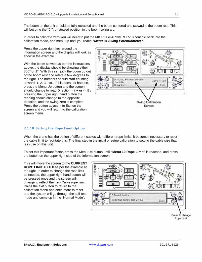
With the boom stowed as per the instructions above, the display should be showing either 360° or 1°. With this set, pick the boom up out of the boom rest and rotate a few degrees to the right. The numbers should start counting upward, 1, 2, 3, etc.. If this does not happen, press the Menu Up button and the screen should change to read Direction = ( + or -). By pressing the upper right hand button the reading should change to the opposite direction, and the swing zero is complete. Press the button adjacent to Exit on the screen and you will return to the calibration screen menu.
2.1.10 SettingtheRopeLimitOption
When the crane has the option of different cables with different rope limits, it becomes necessary to reset the cable limit to facilitate this. The final step in the initial or setup calibration to setting the cable size that is in use on this unit.
To set this important factor, press the Menu Up button until “Menu 10 Rope Limit” is reached, and press the button on the upper right side of the information screen.
This will move the screen to the CURRENT ROPE LIMIT = XX.X as per the example at the right. In order to change the rope limit as needed, the upper right hand button will be pressed once and the screen will change to reflect the new Cable rope limit. Press the exit button to return to the calibration menu and once more to reset and the system will go through the self-test mode and come up in the “Normal Mode”.


SkyAzúl, Equipment Solutions www.skyazul.com 301-371-6126
SkyAzúl, Inc. 16 Walnut Street Middletown, MD 21769 Phone 301-371-6126 Fax 301-371-0029 [email protected] www.skyazul.com


