+ All Categories
Home > Documents > MICRO THERMO TECHNOLOGIESicemeister.net/files/controllers/Micro_Thermo/SUPERM… ·  ·...

MICRO THERMO TECHNOLOGIESicemeister.net/files/controllers/Micro_Thermo/SUPERM… ·  ·...

Date post: 27-Mar-2018
Category:
Upload: vokhanh
View: 218 times
Download: 1 times
Share this document with a friend
51
MICRO THERMO TECHNOLOGIES !!"# $ % & $# ! ’ ! # !#%# #& (& !’ #$ )* ** + ,,-"% !’ !! ’$ !!% !’ ./0*" #0$ !#1*#*#23 4/ !5 6.7 88/---9( 5 6.7 88/8,. !!* 5 ///888!! )35 ///,8/
Transcript

M I C R O T H E R M O T E C H N O L O G I E S

������������ ��������� �

����������� ��������������������

� ���� �� ���� ������� ���!! "� ����� ��� #��$� �� ���������� �� ��% ������ &������$��#���!� ��'�!��������#���������!#��������%#�� ����� #&����������(�����&�����������������������������������!�'���#� �$�������)�**��� �*�����������+ ,,�����- "% ����� ������ ������!�'�����!!��'��������$� ������������!!%�

�����������������!�'���./�0�*��"�����#0�$�!#1*#*��� �#2�3�4/��!������56�.�788/�-�--9�(56�.�788/��8,.

��!!�����*��� �5 �///�88�� ��8��!!�����)3�5 �///�,���8�/�

������ ������ ��������� �

����������������������� ������ ��������� ���������������������������������������������������������������������

�� !��"#��"�������� !��"#��"�������� !��"#��"�������� !��"#��"����������

� �������� �������� ��� ��������� �����������������������������������������������

� ���00:�*�3);�3<3���3������������������������������������������������������������������������������������������������

� ������������ ��� ��� ��������������������������� �����������������������������������������������������������������������������������������������������������������������

�� =��3>�0*>�=)��� ���������������������������������������������������������������������������������������������������������, ��� 0>?>�43*>��):*��:>3��?>�4 ������������������������������������������������������������������� � ��- ��3*�:=�:>���>0�>9*>��>00��3:�2��:99�������00:�*�3<3���3);�3<3���3��������������������������������������������������������������������������������������������������������������������� ��-� ���!!��������������'3�"�3%��������������������������������������������������������������������������������������������������������������� ��-�� �����'�������3�"�3%����������������������������������������������������������������������������������������������������������������������������������� � ��-�- 2�����'@����*�� �������'62��*73�"�3%������������������������������������������������������������������������������������������� - ��-�� 0�'����'3�"�3%�������������������������������������������������������������������������������������������������������������������������������������������� �

� ������ ��������������������������������������������������������������������������������������������������������

-� ��.��9��:0<:=)��>)�=)�*>9:�)���:> ������������������������������������������������������ . -�� -��A��;0�>9���00:�*�*>��>00��)3:��2�.��9��:0< ���������������������� .

� ����������� ���� ������������������������������ ��

�� ��9�:�����:>3<3���*>��>00��3 ������������������������������������������������������������������������ / �� � *�� �����*�����!!��6��.��#��.�/����. �7 ������������������������������������������������������������������������������ / �� �� 3������=�������*�����!!��6��.��7��������������������������������������������������������������������������������������������������������� , �� �- *���������*�����!!�� ������������������������������������������������������������������������������������������������������������������������������������� �� �� �����'�������*������*�����!!�� ��������������������������������������������������������������������������������������������������������������������� �� �. 3�"�*��!��'3%����*�����!!������������������������������������������������������������������������������������������������������������������������� ��� 2��**>��>00�� ����������������������������������������������������������������������������������������������������������- ���� ��������)���*�����!!��6��.��#��.�/����. �7 �����������������������������������������������������������������������- ����� �����������)���*�����!!��6��.��#��.�/����. �7�������������������������������������������������������������� ����- ���!=���6��.�/7*�����!!������������������������������������������������������������������������������������������������������������������������. ��- 0:�2�:�*>��>00��3���������������������������������������������������������������������������������������������������8 ��-� ��!�%0�'����'*�����!!�� ��������������������������������������������������������������������������������������������������������������������������������8 ��-�� ���0�'��*�����!!��6��.��7 �����������������������������������������������������������������������������������������������������������������������

������������������������������������������������������������������������������������������������������������������������

� ������������������� � ������!�� ���������� ������

� =)�=>3�>9�3)=�����4����9�:�����:>3<3��� ����������������������������������������������, �� >=����:>���<=�>9��9�:�������*�3�3���������������������������������������������������������, �- �2���>�<��:*=�:*:=0�3>9��9�:�����:>�����������������������������������������������������-� �� ��9�:�����:>3<3���*>�=>��3��9)*�:>3 ������������������������������������������- �. ��9�:�����:>*<*0������������������������������������������������������������������������������������������������������-- �8 ��9�>3�:�*<*0������������������������������������������������������������������������������������������������������������-� �� 2�����*0�:��B*2������������������������������������������������������������������������������������������������-�

� ���������������������� � ���� ������� ���������������������

������ ������ ��������� �

����������������������� ������ ��������� �������������������������������������������������������������������$�

�� =)�=>3�>9�2�2��*3<3��� �������������������������������������������������������������������������������������-. ��� ��*2�:*�0*>�=>��3>9�>>9��>=):�3 ������������������������������������������������������-8 ���� �����"!�"�!�& �����"��������������!���������������������������� ��������������5 ����-8 ��- �0�*��>:**>�=>��363�3>�37>9�>>9��>=):�3 ������������������������������������-� ��-� �����"!�"�!�& �����"������!������������������������������������ ��������������5�������-� ��� 2���:�*<*0� �����������������������������������������������������������������������������������������������������������������-� ��. ��2)�:�:9:*��:>*<*0� ����������������������������������������������������������������������������������������������-/ ��8 �:��*>�:�:>:�*<*0� ����������������������������������������������������������������������������������������������-,

� ������������������!���!������ ������������������������������������������

-� ��3*�:=�:>>9�0:�2�:�*>��>03<3��� ����������������������������������������������������������� ����"���!���!�#���� ����������������������������������������������������������������������������������������������������������������� ����"������������������!���!������ ������������������������������������������������������������������� ������"��$%&'(������������������������������������������������������������������������������������������������������������������������������������������������������������������� -�� *>9:�)�:�0:�2�:�*>��>03 ������������������������������������������������������������������������������� -�- 0:�2�:�*>��>03������<:�2�3)=�����4�� ������������������������������������������������

������ ������ ��������� �

����������������������� ������ ��������� ���������������������������������������������������������������������

���� "%��%&�' ��(�)��*�����&� ��������"%��%&�' ��(�)��*�����&� ��������"%��%&�' ��(�)��*�����&� ��������"%��%&�' ��(�)��*�����&� �������� ����

1.1 MT Alliance Sub-Systems ������!!������%�����������&����!������ �������������&�������!!�'��� �����"��� �� �!�� C��&� �� ������ � �� ��!� ������� �� ������! � ��������C��D� ��"��%�����69�'��� � 75

• ���������'��"��%����

• �����'���������"��%����

• 2��*��"��%����

• !�'����'��"��%����

• ����'%����'�������"��%������������������� ����������������������'����� ������������� �%�����$������ ��������C�������������'�%������� ����!���&�����������"!���� ������� ��'����"���'!����� ���������������������C�"�����!����'������ ����3�����������!!� ����������'����� ������������������������������������'����� ������ ��� ����#��&�!!�� ���������� �� ��������'��������������������5

• 0�&��!�������������'�����"!��!���

• )����!�������������'�����"!��!���

• =��'�����"!��!����������

• =��'�����"!��!�������!!����������������'��"��%�������������������!!�&��'���������5

• ��� ����������������������������'���������������!��'�����$�!

• 3�$�������� ������������ �������6-7%����

• ����!�%� ��� $������ �%��� �� ��� ���� ����� �� ��� �����'����� ����� �� �������������� ��'������������

• ��������!!% ���!�%� �������������������������������!!��������$� ���'������$��&6��'���� ���� �-7#&���� ���!�%�������������� ��� �����'����� �����# ��� �%������� ����� ���� ������ ������ ��� ������������?�����������'����� ����������������(��� �������'����� !�����6!�&��!����#�����!������ �!����������7#������!!������%����5

• :� ������ ��� !������� �� ��� ���� ���� ���''��� ��� ��� �!��� "% ����'��' ��������'����� ������!������'��������

• ������������$���������!���&�� �&5�!������'��#������ �����

• '�����������!�����'��!������!���*�����

������ ������ ��������� �

����������������������� ������ ��������� �������������������������������������������������������������������+�

��������!������"�������$��� #������������C��&!� '� ����!����� ��C����������!$�������"!���������!!������%�������$� ������������� �������� ������������#&������C��������������������������&����C��&!� '� ����!��������������� �������������!�2��*�E�������5������������#������!������'�� ������� �������'#F���������!!���#����?�����#��������� G������������������� ���� ��%�������������� ������������������������C��69�'��� ��7����� �������� �� ������ �� ��� �� ���'��� !�'����' ���� �!�� 69�'��� �.7 "��� �� �����������C��D�������'�� �!����'�����#��&�!!����������! �%�������!�'�!��!� �%��������"��%�����!��������!������������%����������C��!�'���"��� ������������ ��'!�'����������% ������ "%����������!!�������

������ ������ ��������� �

����������������������� ������ ��������� �������������������������������������������������������������������,�

9:�)�� �

Sub-Systems Description Monitoring The main functions of the monitoring sub-system are:

• monitoring the different types of sensors: case temperature, end-of-defrosting cycle sensor

• saving sensor information in the MT Alliance and drawing graphs based on this information

• generating local alarms when the temperature exceeds the limits and acknowledges them

• sending alarms to the Alarm Center Refrigeration

The main functions of the refrigeration sub-system are: • maintaining case temperatures so as to protect products • defrosting cases according to a preprogrammed schedule

HVAC

The main functions of the HVAC sub-system are: • maintaining a comfortable temperature in the occupied zones during occupancy

mode • lowering the temperature while in inocuppancy mode • maintaining adequate humidity in the main area of the supermarket in order to

reduce the frequency of defrosting in the refrigerated cases Lighting

The main functions of the lighting sub-system are: • maintaining adequate light intensity (clients & employees) in the various zones • lowering or turning off lights according to a programmed schedule

Energy Management

The main functions of the energy management sub-system are: • reducing energy consumption of the sub-systems by means of effective control

strategies • controlling electrical loads (load shedding) during periods of high energy

consumption

M T A llian c e S u b -S y s te m s

R efr ig e ra tio n S y stem

L ig h tin g S ys te m

M o nit o r ing S y stem

H V A C S y s tem

In te r fac eH u m ai ns- M ac h i ne s

O t he r S y stem s

E n e r g y M a na g e m e n t

S ys t e m

������ ������ ��������� �

����������������������� ������ ��������� ���������������������������������������������������������������������

>$��$��&�����!!�����3%����5

9:�)�� ��H���� $��&�����!!�����3%����59:�)�� �-

��"��������$��!����

*!��C����C��&!� '�

3�����&����!������''���

����$��!����

�!������C��&!� '� ���&�

���!"��

3�����"��

����"��

������ ���������

*����������

������ ������ ��������� �

����������������������� ������ ��������� �������������������������������������������������������������������-�

���&���&�� �&���� G�����'�����������5

9:�)�� �����&���!�'����'���� �!�5

9:�)�� �.

�����!�����������'�#�!��C�� ��$���������

��3�!����!�'�������"%�!��C��'I2�'�I#J�� ���K#K0�&K��J>��K

��%�����%����!&��C

3�!�����%����!&��C�� ��������&��C!%���� �!�

��������������� &�!!������������������� �!������ ��'!%

���"!��!�����������������������������'����

:��������� ��������������������L

L 3!� �����������

������ ������ ��������� �

����������������������� ������ ��������� �������������������������������������������������������������������.�

���� ���)&�������(���)&�������(���)&�������(���)&�������(���*�����&� ���/&��&0������ ��������� ����*�����&� ���/&��&0������ ��������� ����*�����&� ���/&��&0������ ��������� ����*�����&� ���/&��&0������ ��������� �����

9:�)���� ��� �����"��� ������!�%����������������C������ ����������!!�&��'����������5

• ��������!��������• �0��?��C������������������&��C• �!���������� �!����!!� �� ����������!!���������������������������������!!�������"��%�����

2.1 Personal Computer �������������!!�&�������������� ���������$�'��������'���� �����������!!�������"��%������ ���������# ��� �������! �������� �� ��� �� ����% ��� ��� ��!!�&��'����������5

• *����'����'���������!!�������� ����������"��%�����• 3�� ��'��������'������������������!!���$�����0��?��C������������������&��C

• ���������'�� ������!!��'��� ����������"��%�����• ����"!��������'���������!���"!�������"��%��������'���!%������!�

Distributed Control System for a Supermarket

RTC

Monitoring Sub-System for Refrigerated Cases

SN26

SN27

SN28

SN63

ALRTRM Refrigeration Sub-System (Rack A)

HVAC Sub-System

Lighting Sub-System

SN 25

1 8

CND SPC CM P1

CM P 2

CKT1

CM P3

CKT2

CKT3

SN29

DPUH

SCHRTU VA V

VA V1

VA V2

ESCH PTC LCU

1LCU

2LCU

3 DIM

5 Circuits

Inte rface

User

LegendTRM : Network Terminat ion

ALR: A larm Controller

RTC : Real T ime C loc k

SN : Sensor N ode

CND: Conde nser Controller

SP C: Suction P ressure Controller

CMP: C ompressor Controller

CKT: C ircuit C ontroller

ATS : Anti-Sweat Controller

SCH : Scheduler

DP U: Dua l P ath Control

RTU : R oof- top Unit C ontroller

VAV: VAV Box Control

PTC: Photoce ll Sensor

LCU: L ight Control Unit

DIM : D immer Control

Total 64 nodes

500 metres

Sensors

SN30

SNxx

Central alarm system

FTT Network

Re mote communication

PC Anywhe re , Page r, e tc.

VA V3

ATS

������ ������ ��������� �

����������������������� ������ ��������� ����������������������������������������������������������������������

:�� �����"��� �%����#������!!��'��"��%������������� ���"%��� ����������"��%����������!!����� ���"% ����������! ��������� ���������#�� ��� =* �������#��"��%��������������������� ���"%��� ��������������!!����� ����!����������� ������!���*������>�!% �����������������#&������������!!%��$� #&�!!"�!�������������������������

2.2 LonWorks Communications Network

���0��?��C�9��6��������!�'%7���&��C���� �������������&���� &��������!��C���������!!��������������&����������������������������!!����������������!�'%������!����% �� ��� &��� ����� ��� "� ��$���� �� ��� ��������� �� ���� ������!!�� &������������' ��������'���"!���&��� ������!!����� 3%����� �����$��� ��� ���!������ ����'��!���������&��C#������&��C������$������������������6�� ����!�����������7�

���0��?��C����&��C�!!������� ����� ��'���69�'����� 7��!����� ��8��� ���� ������!!��'����.���������:�����������!��������#���&��C�������%���"��������� �� ���� ���� �������!!��'���� #.��������#�����'����� ��������&����&��C���!������6��������7�

��������������������&��C���������������������5

• 3�� ��'�������������������6�����'�������������'�#���������7�����������!!���• 3�� ��' ������!!�� ����������� 6������ �� ������� ��'��!�# �������% �$��� �� ����������������7�������������

• 3�� ��'�����������"��&���������!!���

*������������� ����&��� �� ��� ���� �� ���� ������!!�� �� ��� �� ��� ��� "��&���������!!���#�� "��&��� ���������!!����� =*� ��� ��!��"�!��%�� ������������� �����"��%�������������� "%�����"������������������������������&������������&��������� ������������"��&���������!!����� "��&������������!!����� =*��!!�&��'5

• ���!!������� ����������������$��������&��C�• )����������! ����(����'�"��&����&�������!!�����������&��C�

������ ������ ��������� �

����������������������� ������ ��������� ����������������������������������������������������������������������

2.3 Description and Role of Controllers in the Different MT Alliance System Sub-Systems

2.3.1 MT Alliance Monitoring Sub-System

��� ��"!� "�!�& !���� $������ �%��� �� ������!!��� �� �� �!��# �� &�!! �� ��� �������������������������!!����������������'3�"�3%��������������� ��'����!!��������'���������"��� *�����!3%��������3�������C��69�'����� 7�

Controllers/Node Legend Modules Functions

Sensor Node

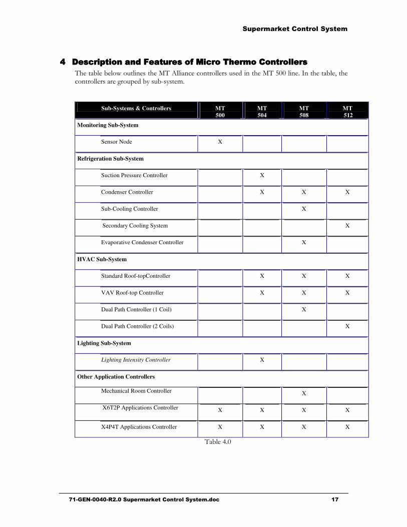
SN MT 500 The sensor node is used to monitor eight (8) sensors and generate an alarm if the signal from a sensor exceeds the low or high limit programmed in the node. Different types of sensors can be connected to each input: Temperature sensor for refrigerated cases, temperature sensors for the end of defrosting, refrigerant leak detector, etc.

Real Time Clock

RTC Real Time Clock Normally, the computer’s clock synchronizes with the clock in each controller on the network by regularly sending the time over the network. When the computer crashes, the real-time clock takes over the computer and takes over this function.

Alarm Controller

ALR Alarm Controller When a sensor node generates an alarm, the information is sent to the computer and alarm controllers: • The computer displays the alarm in the alarm banner • The alarm controller sends the alarm to the Alarm Center

������ ������ ��������� �

����������������������� ������ ��������� ����������������������������������������������������������������������

2.3.2 Refrigeration Sub-System

�����"!�"�!�&!�������$�������%�����������!!��������������'���������"��%����#����� �!��%���� ����������������������������!!������������� ��'����!!��������'���������"��� *�����!3%��������3�������C��69�'����� 75

Controllers////Node Legend Modules Functions Condenser Controller

CND MT 504 MT 508 MT 512

The condenser controller is used to maintain the condenser temperature at a temperature higher than the outside temperature; this allows accumulated heat to be evacuated from the refrigeration circuit. The controller carries out this function by comparing the pressure/temperature measured in the condenser at a programmed set point and starts one or more fans based on the difference of these two values. When the condenser temperature is higher than the outside temperature, the heat accumulated in the gaseous refrigerant from the refrigerated cases is released into in the ambient air. This also causes the gaseous refrigerant to liquefy. The condenser controller can control up to twelve (12) fans with a MT 512 module.

Suction Pressure Controller

SPC MT 504 The purpose of the suction pressure controller is to control the pressure of the refrigerant in the suction manifold. The controller carries out this function by comparing the pressure/temperature measured in the suction manifold to a programmed set point, and the controller starts one or more compressors based on the difference of these two values. The suction pressure controller can control up to ten (10) compressors.

Compressor Controller

CMP Compressor Ctrl In the refrigeration control system, there is one compressor controller for each mechanical compressor. Each compressor controller receives its start or stop command from the suction pressure controller to maintain the refrigerant temperature in the suction manifold. After receiving a start command, the compressor controller checks the compressor securities (oil pressure, compressor temperature, etc.). If conditions are normal, the compressor controller starts the compressor. If one of the security devices sends an abnormal condition signal, the compressor controller generates an alarm and stops the compressor from starting.

Circuit Controller

CKT Circuit Ctrl The refrigeration circuit controller controls the refrigeration and defrosting cycle of the refrigerated cases connected to a circuit. A refrigeration system can have up to forty (40) circuits. All refrigerated cases on a circuit are defrosted simultaneously according to a preprogrammed schedule. The circuit controller carries out this operation by controlling the opening and closing of the refrigeration and defrosting valves of a circuit based on a programmed defrosting schedule.

Anti-Sweat Controller

ATS

AntiSweat Ctrl In a glass refrigerated case, the anti-sweat controller prevents: • The formation of sweat on the case glass • The door to stick in the door frame. The anti-sweat controller carries out this function by measuring the humidity in the store by comparing it to a set point and, based on difference between these two values, the glass and door frame of the case are heated up accordingly.

������ ������ ��������� �

����������������������� ������ ��������� ��������������������������������������������������������������������$�

2.3.3 Heating/Air-Conditioning (HVAC) Sub-System

�����"!�"�!�&!�������$�������%�����������!!���������2��*��"��%����#����%������ �!���� ����������������������������!!��� ����� �� ��� ��'����!!��������' ���������"��� *�����!3%��������3�������C��69�'����� 75

Controllers////Node Legend Modules Functions Roof-Top Controller

Scheduler RTU MT 504

MT 508 MT 512

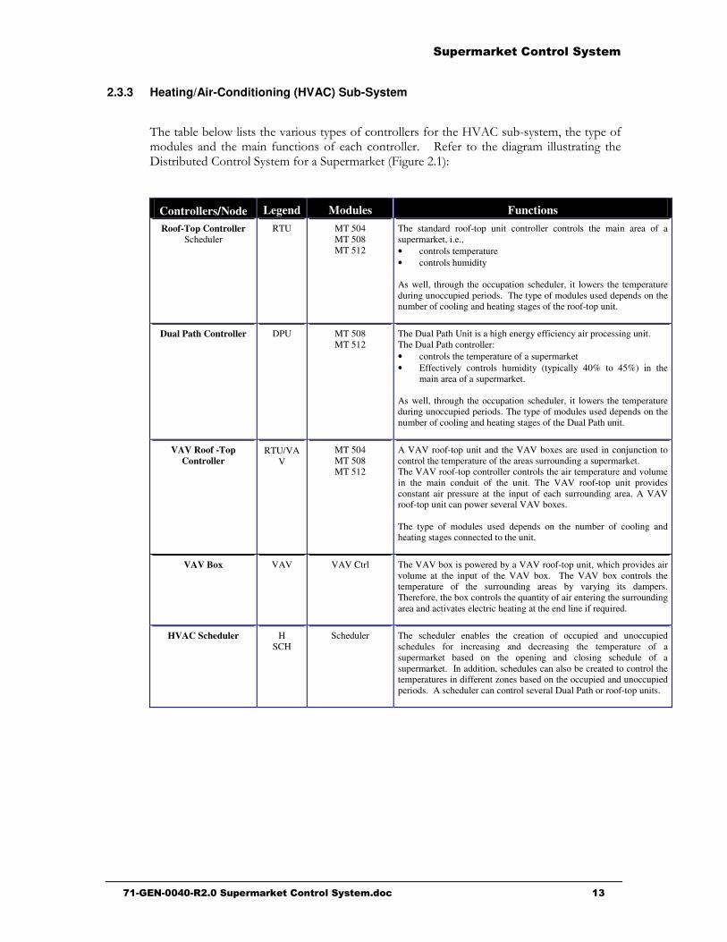
The standard roof-top unit controller controls the main area of a supermarket, i.e., • controls temperature • controls humidity As well, through the occupation scheduler, it lowers the temperature during unoccupied periods. The type of modules used depends on the number of cooling and heating stages of the roof-top unit.

Dual Path Controller

DPU MT 508 MT 512

The Dual Path Unit is a high energy efficiency air processing unit. The Dual Path controller: • controls the temperature of a supermarket • Effectively controls humidity (typically 40% to 45%) in the

main area of a supermarket. As well, through the occupation scheduler, it lowers the temperature during unoccupied periods. The type of modules used depends on the number of cooling and heating stages of the Dual Path unit.

VAV Roof -Top Controller

RTU/VAV

MT 504 MT 508 MT 512

A VAV roof-top unit and the VAV boxes are used in conjunction to control the temperature of the areas surrounding a supermarket. The VAV roof-top controller controls the air temperature and volume in the main conduit of the unit. The VAV roof-top unit provides constant air pressure at the input of each surrounding area. A VAV roof-top unit can power several VAV boxes. The type of modules used depends on the number of cooling and heating stages connected to the unit.

VAV Box

VAV VAV Ctrl The VAV box is powered by a VAV roof-top unit, which provides air volume at the input of the VAV box. The VAV box controls the temperature of the surrounding areas by varying its dampers. Therefore, the box controls the quantity of air entering the surrounding area and activates electric heating at the end line if required.

HVAC Scheduler

H SCH

Scheduler The scheduler enables the creation of occupied and unoccupied schedules for increasing and decreasing the temperature of a supermarket based on the opening and closing schedule of a supermarket. In addition, schedules can also be created to control the temperatures in different zones based on the occupied and unoccupied periods. A scheduler can control several Dual Path or roof-top units.

������ ������ ��������� �

����������������������� ������ ��������� ����������������������������������������������������������������������

2.3.4 Lighting Sub-System

��� ��"!� "�!�& !���� ��� �������� �%��� �� !�'����' ��"��%���� ������!!���# ��� �%�� ���� �!���� ������� ����������� ���� ������!!��� ����� �� ��� ��'����!!��������' ���������"��� *�����!3%��������3�������C��69�'����� 75

Controllers////Node Legend Modules Functions Lighting Controller

LCU Gentec: - Input Board

- Output Board - Panel Relay

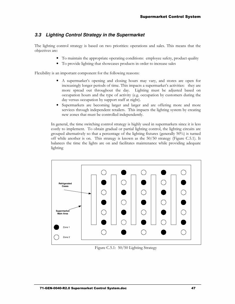
The indoor and outdoor lighting system of a supermarket is: • subdivided in the lighting zones • each zone includes one or more illuminating lights • each lighting zone is controlled by a lighting schedule

originating from the lighting scheduler.

The lighting controller of a supermarket includes the following: • an eight-switch input module. Each switch can be used to

override the lighting schedule of a zone in order to manually control it

• a 16-output power module that powers the 16 relays of the lighting panel

• 16-relay panel. Each relay is connected to one or more illuminating lights. Lighting configuration software groups together 16 relays of the lighting panel per zone.

The lighting controller controls the indoor and outdoor lighting zones of a supermarket based on: • a schedule programmed in a lighting scheduler or even • the combination of a schedule and outdoor photocell.

If the light intensity measured by the photocell sensor is higher than the programmed set point, the controller overrides the lighting schedule and cancels the lighting in one or more zones of the supermarket.

Lighting Intensity Controller

DIM DimLight The lighting intensity controller is used with the Lighting controller and photocell sensor. It controls the lighting intensity of the lights of a zone based on the light intensity measured by the photocell sensor located in the zone.

Photocell Sensor PTC Douglas - Photocell Sensor

The photocell sensor is used to measure the light intensity outside a supermarket or within a zone of the supermarket. The photocell sensor signal is sent to the lighting controllers throughout the communications network.

Light Scheduler

L SCH

Scheduler The scheduler creates the lighting schedules in order to control the lighting based on the opening and closing hours of the supermarket. As well, the schedules can also be created to individually control the lighting in different zones based on occupied and unoccupied periods. Several schedules can be created on a single scheduler. A schedule can control one or more zones.

������ ������ ��������� �

����������������������� ������ ��������� ��������������������������������������������������������������������+�

$$$$ *��+���#�� &��*��+���#�� &��*��+���#�� &��*��+���#�� &������

3.1 MT 500 Family Input-Output Configuration

��� �� .�� ����!% �� � !��� �� �!�������� �� �!�� �$�!��� "% ����� ������������!�'���� ��� �� �!�� �� ��� �� .�� ����!% ��$� � $�����% �� �����������������'����������� ����������������C�����!��������������"!�"�!�&���&���� ���������� �!��������.������!%�� ����������'���������

M T 5 0 0 F a m i l y I n p u t - O u t p u t C o n f i g u r a t i o n

M T 5 0 0 M T 5 0 4 M T 5 0 8 M T 5 1 2

A n a l o gI n p u t s

8 8 8 8

D i g i t a lI n p u t s

4 8

D i g i t a lO u t p u t s

4 8 1 2

A n a l o gO u t p u t s

4 4 4

��;0�-�

3.2 3.2 – Table of MT Alliance Controller using the 500 Family

MT 500 Family Specifications

MT-504 MT-508 MT-512

Applications See Section 4.0 for the different MT 504 applications

See Section 4.0 for the different MT 508 applications.

See Section 4.0 for the different MT 512 applications.

Universal Inputs Eight (8) universal inputs (analog or digital): 0-5 V, 0-10 V, 4-20 mA, 10 K Thermistor. Low-pass filter on each input.

Eight (8) universal inputs (analog or digital): 0-5 V, 0-10 V, 4-20 mA, 10 K Thermistor. Low-pass filter on each input.

Eight (8) universal inputs (analog or digital): 0-5 V, 0-10 V, 4-20 mA, 10 K Thermistor. Low-pass filter on each input.

Digital Inputs None Four (4) digital inputs: Each input is optically isolated (0-15V)

Eight (8) digital inputs: Each input is optically isolated (0-15V)

Digital Outputs Four (4) type-C relays: SPDT, 2A, 250 VAC. Protected by fuses on the module

Eight (8) type-C relays: SPDT, 2A, 250 VAC. Protected by fuses on the module

Twelve (12) type-C relays: SPDT, 2A, 250 VAC. Protected by fuses on the module

������ ������ ��������� �

����������������������� ������ ��������� ��������������������������������������������������������������������,�

MT 500 Family Specifications

MT-504 MT-508 MT-512

Analog Outputs Four (4) configurable analog outputs: 0-20 mA, 0-5V, 0-10V, 2-10V. Protected by a current limiter (max 20 mA )

Four (4) configurable analog outputs: 0-20 mA, 0-5V, 0-10V, 2-10V. Protected by a limiting current limiter (max 20 mA )

Four (4) configurable analog outputs: 0-20 mA, 0-5V, 0-10V, 2-10V. Protected by a limiting current limiter (max 20 mA )

Dimensions 8.0” x 4.0” x 1.5” 204 mm x 102 mm x 38 mm

12.25” x 4.0” x 1.5” 312 mm x 102 mm x 38 mm

16.375” x 4.0” x 1.5” 416 mm x 102 mm x 38 mm

Set-up Mounted on wall or on snaptrack

Mounted on wall or on snaptrack

Mounted on wall or on snaptrack

Power 24 VAC transformer 12 VA with center tap

24 VAC transformer 12 VA with center tap

24 VAC transformer 12 VA with center tap

Environment -40 to 75°C (-40 to 168°F) 5% to 95% R.H.

-40 to 75°C (-40 to 168°F) 5% to 95% R.H.

-40 to 75°C (-40 to 168°F) 5% to 95% R.H.

Certification UL, CSA approved

UL, CSA approved

UL, CSA approved

��;0�-��

������ ������ ��������� �

����������������������� ������ ��������� ����������������������������������������������������������������������

���� /����&�&� �� ��#��������(�*&�����)��� ���� �������/����&�&� �� ��#��������(�*&�����)��� ���� �������/����&�&� �� ��#��������(�*&�����)��� ���� �������/����&�&� �� ��#��������(�*&�����)��� ���� �����������

�����"!�"�!�&���!����������!!�����������!!������ �������.��!����:������"!�#���������!!������'����� "%��"��%�����

Sub-Systems & Controllers MT 500

MT 504

MT 508

MT 512

Monitoring Sub-System

Sensor Node X

Refrigeration Sub-System

Suction Pressure Controller X

Condenser Controller X

X X

Sub-Cooling Controller X

Secondary Cooling System X

Evaporative Condenser Controller X

HVAC Sub-System

Standard Roof-topController X

X X

VAV Roof-top Controller X

X X

Dual Path Controller (1 Coil) X

Dual Path Controller (2 Coils) X

Lighting Sub-System

Lighting Intensity Controller X

Other Application Controllers

Mechanical Room Controller X

X6T2P Applications Controller X X X

X

X4P4T Applications Controller X X

X X

��"!����

������ ������ ��������� �

����������������������� ������ ��������� ��������������������������������������������������������������������-�

4.1 Refrigeration System Controllers

4.1.1 Condenser Controller (MT 504, MT 508 or MT 512)

Inputs Alarm Outputs Control Configuration and Strategy Analog: UI1 *Discharge Pressure (DP) 1 UI2 *Condenser Inlet Press (CIP) UI3 *Condenser Outlet Press (COP) UI4 *Drop Leg Temp (DLT) UI5 *Outdoor Air Temp (OAT) UI6 * Liq Header Press (LHP) IU7 * Liq Header Temp (LHP) UI8 Inverter Fault IIVF) Digital: None

Yes

Yes

Yes

Yes

Yes

Yes

Yes

Yes

Analog: AO1 Variable Speed Drive (VFD) Digital: - MT504: DO1 Fan 1 … … DO4 Fan 4 - MT 508: DO1 Fan 1 … DO8 Fan 8 - MT 512: DO1 Fan 1 … DO12 Fan 12

Control Configuration and Strategies Condenser Type: Air , Evaporative (See Note) Condenser Config.: One or two rows No. of Fans: Max. 12 fans Control Point: Selection from sensors

on physical and logical inputs. Operating Set Point: Pressure/Temperature depending on the sensors chosen Conversion Table: Pressure/Temperature conversion (depending on the type of refrigerant) Control Strategy: Single: DP, COP, DLT, etc. Differential (floating Head): OAT & COP OAT & DLT etc. Control Type PID, Sequential Primary Fan: Fixed speed, variable speed, cycling Split Mode Control Strategy and Configuration Configuration: Split on outdoor temperature Split on Heat Reclaim 1 Split on Heat Reclaim 2 Split on Heat Reclaim 1 & 2 Split on Out Temp and Heat Reclaim Set Point: - Split Temperature Set Point - Unsplit Discharge Press Set Point - Unsplit Discharge Press Auto Reset - Split Minimum On Time Note: Evaporative condenser controller (MT 508) A specific plug-in is used for configuring and adjusting the set points and monitoring the evaporative condenser.

�!!��������''� &�����MNO��������"!�#�� ����"��E������"!��6����'������� � �����'����-��7#��������������������'��!����!�����'������������0��?��C���&��C6!�'���!����������7�

������ ������ ��������� �

����������������������� ������ ��������� ��������������������������������������������������������������������.�

Suction Pressure Controller (MT 504)

Inputs Alarm Outputs Control Configuration and Strategy

Analog: UI1 *Discharge Pressure (DP) UI2 Suction Pressure (SP) UI3 Liquid Header Press (LHP) UI4 *Heat Reclaim1 (HR1) UI5 *Heat Reclaim 2 (HR2) UI6 *Phase Lost (PLM) UI7 Refrig Leak Sensor (RLS) UI8 *Suction Pressure Shift (ECE) Logical Network Variables (SNVT) * Main Defrost Valve Logical connection to Circuit controller * Split Valve Logical connection to Condenser controller

Yes

Yes

Yes

Yes

Yes

Analog: OA1 Compressor Variable Frequency Drive (VFD) Digital:

DO1 Heat Reclaim 1 DO2 Split Valve DO3 Main Defrost DO4 Heat Reclaim 2

Control Configuration and Strategies

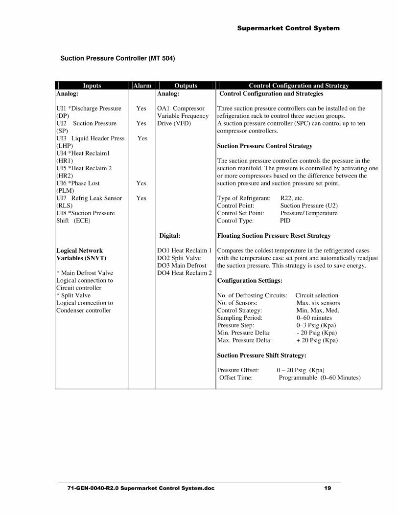
Three suction pressure controllers can be installed on the refrigeration rack to control three suction groups. A suction pressure controller (SPC) can control up to ten compressor controllers. Suction Pressure Control Strategy The suction pressure controller controls the pressure in the suction manifold. The pressure is controlled by activating one or more compressors based on the difference between the suction pressure and suction pressure set point. Type of Refrigerant: R22, etc. Control Point: Suction Pressure (U2) Control Set Point: Pressure/Temperature Control Type: PID Floating Suction Pressure Reset Strategy Compares the coldest temperature in the refrigerated cases with the temperature case set point and automatically readjust the suction pressure. This strategy is used to save energy. Configuration Settings: No. of Defrosting Circuits: Circuit selection No. of Sensors: Max. six sensors Control Strategy: Min, Max, Med. Sampling Period: 0–60 minutes Pressure Step: 0–3 Psig (Kpa) Min. Pressure Delta: - 20 Psig (Kpa) Max. Pressure Delta: + 20 Psig (Kpa) Suction Pressure Shift Strategy: Pressure Offset: 0 – 20 Psig (Kpa) Offset Time: Programmable (0–60 Minutes)

��������

������ ������ ��������� �

����������������������� ������ ��������� ����������������������������������������������������������������������

4.1.2 Compressor Controller ��

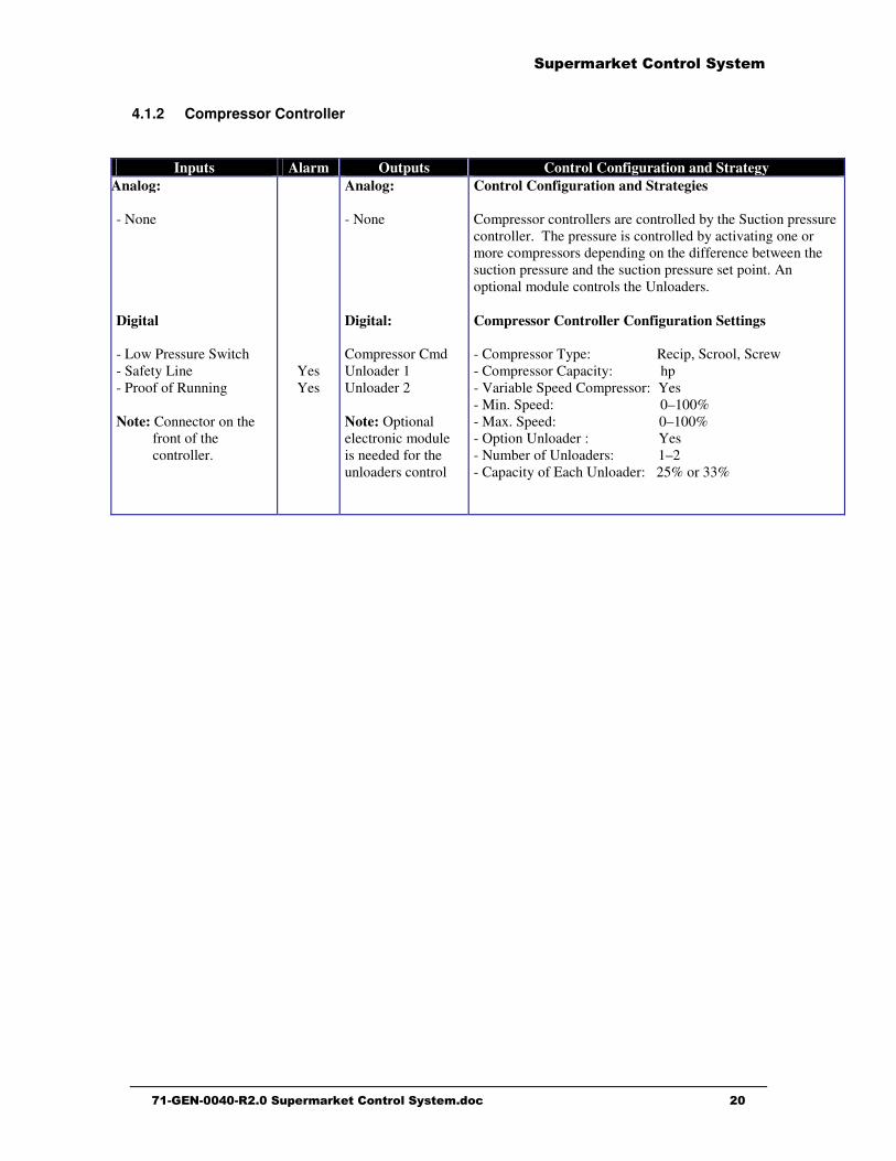
Inputs Alarm Outputs Control Configuration and Strategy Analog: - None Digital - Low Pressure Switch - Safety Line - Proof of Running Note: Connector on the

front of the controller.

Yes Yes

Analog: - None Digital: Compressor Cmd Unloader 1 Unloader 2 Note: Optional electronic module is needed for the unloaders control�

Control Configuration and Strategies Compressor controllers are controlled by the Suction pressure controller. The pressure is controlled by activating one or more compressors depending on the difference between the suction pressure and the suction pressure set point. An optional module controls the Unloaders. Compressor Controller Configuration Settings - Compressor Type: Recip, Scrool, Screw - Compressor Capacity: hp - Variable Speed Compressor: Yes - Min. Speed: 0–100% - Max. Speed: 0–100% - Option Unloader : Yes - Number of Unloaders: 1–2 - Capacity of Each Unloader: 25% or 33%

������ ������ ��������� �

����������������������� ������ ��������� ����������������������������������������������������������������������

4.1.3 Refrigeration Circuit Controller

Inputs Alarm Outputs Control Configuration and Strategy Analog: - None Logical Network Variables (SNVT) * Case Temperature * Defrost Termination * Defrost Termination

Switch * Door Ajar

Analog - None Digital . Defr Valve 1 . Refr Valve 1 . Defr Valve 2 . Refr Valve 2 . Defr Valve 3 . Refr Valve 3 . Defr Valve 4 . Refr Valve 4 . Defr Valve 5 . Refr Valve 5

Control Configuration and Strategies The Circuit controller controls five refrigeration circuits. Up to eight (8) circuit controllers can be used on one rack. Thus, 40 refrigeration circuits can be controlled in the rack. Refrigeration Cycle Control: Mode: - Refrig. Valve on/off control - Mechanical EEPR - Electronic EEPR Control Point: Refrigerated case temperature Control Set Point: Desired case temperature Dead Band Set Point: Prevents cycling Defrosting Cycle Control: Defrosting Type: Hot Gas, Off Cycle, Electric Defrost Strategy: On Time, On Temp, Pulse No. Defrostings/Day: 1–8 Max Defrost Time: Programmable Min. Defrost Time: Programmable Circuit Load: Kilo Btu End of Defrosting Sensor: Analog or Digital No. of Sensors: Max. six sensors Defrosting Strategy: Analog: Min, Max, Med. Digital: On state Pump Down Cycle: Pump Down Time Programmable Drain Cycle: Drain Time: Programmable

������ ������ ��������� �

����������������������� ������ ��������� ����������������������������������������������������������������������

4.1.4 Sub-Cooling System Controller

Inputs Alarm Outputs Control Configuration and Strategy Analog UI1 * Mech Subcooler Temp In (LQT in) UI2 * Mech Subcooler 1 Temp Out (LQTOut 1) UI3 * Mech Subcooler 2 Temp Out(LQTOut2) Digital - None Logical Network Variables (SNVT) - Logical connections to the condenser controller:

* Condenser Saturated Temp * Drop Leg Temp * Outdoor Temp - Logical connection to

the suction pressure controller:

* Suction Pressure

Yes

Yes

Yes

Analog AO1 SPR/CTRL Valve AO2 Receiver Out Valve AO3 Mech Subcooler 1 Valve AO4 Mech Subcooler 2 Valve Digital DO1 Drain Valve DO2 SPR/CTRL Valve DO3 Subcooler 1 Stage 1 DO4 Subcooler 1 Stage 2 DO5 Subcooler 2 Stage 1 DO6 Subcooler 2 Stage 2 DO7 Receiver Out Valve

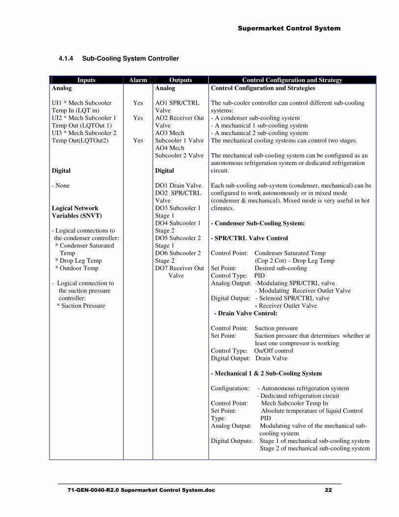
Control Configuration and Strategies The sub-cooler controller can control different sub-cooling systems: - A condenser sub-cooling system - A mechanical 1 sub-cooling system - A mechanical 2 sub-cooling system The mechanical cooling systems can control two stages. The mechanical sub-cooling system can be configured as an autonomous refrigeration system or dedicated refrigeration circuit. Each sub-cooling sub-system (condenser, mechanical) can be configured to work autonomously or in mixed mode (condenser & mechanical). Mixed mode is very useful in hot climates. - Condenser Sub-Cooling System: - SPR/CTRL Valve Control Control Point: Condenser Saturated Temp (Cop 2 Cot) – Drop Leg Temp Set Point: Desired sub-cooling Control Type: PID Analog Output: -Modulating SPR/CTRL valve - Modulating Receiver Outlet Valve Digital Output: - Selenoid SPR/CTRL valve - Receiver Outlet Valve - Drain Valve Control: Control Point: Suction pressure Set Point: Suction pressure that determines whether at

least one compressor is working Control Type: On/Off control Digital Output: Drain Valve - Mechanical 1 & 2 Sub-Cooling System Configuration: - Autonomous refrigeration system - Dedicated refrigeration circuit Control Point: Mech Subcooler Temp In Set Point: Absolute temperature of liquid Control Type: PID Analog Output: Modulating valve of the mechanical sub-

cooling system Digital Outputs: Stage 1 of mechanical sub-cooling system Stage 2 of mechanical sub-cooling system

������ ������ ��������� �

����������������������� ������ ��������� ��������������������������������������������������������������������$�

4.2 HVAC Controller

4.2.1 Roof-Top Unit Controller (MT 504, MT 508 or MT 512) �

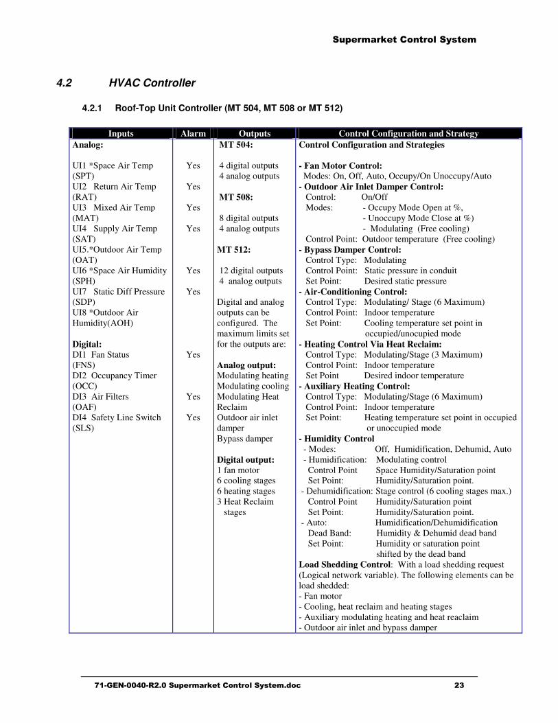
Inputs Alarm Outputs Control Configuration and Strategy Analog: UI1 *Space Air Temp (SPT) UI2 Return Air Temp (RAT) UI3 Mixed Air Temp (MAT) UI4 Supply Air Temp (SAT) UI5.*Outdoor Air Temp (OAT) UI6 *Space Air Humidity (SPH) UI7 Static Diff Pressure (SDP) UI8 *Outdoor Air Humidity(AOH) Digital: DI1 Fan Status (FNS) DI2 Occupancy Timer (OCC) DI3 Air Filters (OAF) DI4 Safety Line Switch (SLS)

Yes

Yes

Yes

Yes

Yes

Yes

Yes

Yes

Yes

MT 504: 4 digital outputs 4 analog outputs MT 508: 8 digital outputs 4 analog outputs MT 512: 12 digital outputs 4 analog outputs Digital and analog outputs can be configured. The maximum limits set for the outputs are: Analog output: Modulating heating Modulating cooling Modulating Heat Reclaim Outdoor air inlet damper Bypass damper Digital output: 1 fan motor 6 cooling stages 6 heating stages 3 Heat Reclaim stages

Control Configuration and Strategies - Fan Motor Control: Modes: On, Off, Auto, Occupy/On Unoccupy/Auto - Outdoor Air Inlet Damper Control: Control: On/Off Modes: - Occupy Mode Open at %, - Unoccupy Mode Close at %) - Modulating (Free cooling) Control Point: Outdoor temperature (Free cooling) - Bypass Damper Control: Control Type: Modulating Control Point: Static pressure in conduit Set Point: Desired static pressure - Air-Conditioning Control: Control Type: Modulating/ Stage (6 Maximum) Control Point: Indoor temperature Set Point: Cooling temperature set point in occupied/unocupied mode - Heating Control Via Heat Reclaim: Control Type: Modulating/Stage (3 Maximum) Control Point: Indoor temperature Set Point Desired indoor temperature - Auxiliary Heating Control: Control Type: Modulating/Stage (6 Maximum) Control Point: Indoor temperature Set Point: Heating temperature set point in occupied

or unoccupied mode - Humidity Control - Modes: Off, Humidification, Dehumid, Auto - Humidification: Modulating control Control Point Space Humidity/Saturation point Set Point: Humidity/Saturation point. - Dehumidification: Stage control (6 cooling stages max.) Control Point Humidity/Saturation point Set Point: Humidity/Saturation point. - Auto: Humidification/Dehumidification Dead Band: Humidity & Dehumid dead band Set Point: Humidity or saturation point shifted by the dead band Load Shedding Control: With a load shedding request (Logical network variable). The following elements can be load shedded: - Fan motor - Cooling, heat reclaim and heating stages - Auxiliary modulating heating and heat reaclaim - Outdoor air inlet and bypass damper

������ ������ ��������� �

����������������������� ������ ��������� ����������������������������������������������������������������������

4.2.2 VAV Roof-Top Unit Controller (MT 504, MT 508 or MT 512) �

Inputs Alarm Outputs Control Configuration and Strategy Analog: UI1 Return Air Temp (RAT) UI2 Mixed Air Temp (MAT) UI3 Supply Air Temp (SAT) UI4 Return Air Pressure (RAP) UI5 Return Air Humidity (RAH) UI6 Mixed Air Filter (MAF) UI7 *Outdoor Air Temp (OAT) UI8 Supply Air Pressure (SAP) Digital: DI1 Fan Status (FNS) DI2 Occupancy Timer (OCC)

Yes

Yes

Yes

Yes

Yes

Yes

Yes

Yes

MT 504: 4 digital outputs 4 analog outputs MT 508: 8 digital outputs 4 analog outputs MT 512: 12 digital outputs 4 analog outputs Digital and analog outputs can be configured. The maximum limits set on the outputs are: Analog: Bypass damper Outdoor air damper Modulating heating Modulating cooling Modulating humidifier Modulating fan Digital: 1 fan motor 6 cooling stages 6 heating stages

Control Configuration and Strategy - Fan Motor Control: Modes: On, Off, Auto, Occupy/On Unoccupy/Auto - Outdoor air inlet damper control: Control: On/Off Modes: - Occupy Mode Open at %, - Unoccupy Mode Closed at % - Modulating (free cooling) Control Point: Outdoor temperature (free cooling) - Humidity Control: Modes: Off, Humid., Dehumid, Auto - Humidification : Modulating control Control Point: Humidity/Saturation point in the return

air Set Point: Humidity/Saturation point. - Dehumidification: Stage control (6 cooling Stages max.) Control Point Humidity/Saturation point in the return

air Set Point: Humidity/Saturation point. - Auto: Humidification/Dehumidification Dead Band: Humidity & Dehumid dead band Set Point: Humidity or saturation point shifted by

the dead band - Supply Air Pressure Control: - Modes: Bypass damper or Fan speed control - Control Point: Supply air pressure - Set Point: Desired supply air pressure - Modulating Out : Bypass damper or Fan speed control - Supply Air Temperature Control: - Mode: - Outside Temp. - Return Temp - VAV box request - Control Type: Modulating or stages - Control Point: Supply air temperature - Set Point Depends on mode: - Supply temp. readjust by outside temperature - Supply temp. readjust by return temperature - Supply temp. readjust by VAV box request Load Shedding Control: With a load shedding request (Network variable), the following items can be load shedded: - Fan motor - Cooling, heat reclaim and heating stages - Auxiliary modulating heat reclaim and heating - Outdoor air intake damper - Bypass damper

������ ������ ��������� �

����������������������� ������ ��������� ��������������������������������������������������������������������+�

4.2.3 Dual Path (MT 508) Controller �

Inputs Alarm Outputs Control Configuration and Strategy

Analog:

UI1*Space Air Temp (SPT)

UI2 Return Air Temp (RAT)

UI3 DX Coil Temp (DXT)

UI4 Supply Air Temp (SAT)

UI5 *Outdoor Air Temp (OAT)

UI6 *Space Air Humidity (SPH)

UI7 Liquid Saturated Temp(LST)

UI8 *DX Coil Diff Press (DXDP)

Digital:

DI1 Fan Status (FNS)

DI2 Occupancy Timer (OCC)

DI3 Return Air Filter (RAF)

DI4 Outside Air Filter (OAF)

Yes

Yes

Yes

Yes

Yes

Yes

Yes

Yes

Yes

MT 504:

� �'���!�����������!�'�������

MT 508:

/ �'���!�����������!�'�������

MT 512:

� �'���!�����������!�'�������

��'���!�� ���!�'����������"������'��� ������(����!�����������������������5

Analog

>���� � �����;%���� ����������� ������� �!����'������'

Digital

9�������8���!��'���'��8������'���'��-���!������'��

�)*'+),��)*-$%.+/'$)*�/*0��'+/'1%2�3�/*��)')+��)*'+),4��� ��5>�#>��#����#>����%@>�#)������%@����3��� 50�&#2�'�#2�'�@>��P����@)����#*���������Q>������������3���/561+��)*'+),4�� G���������� �"%"�!�����'�������������� �5>��;������)�������� RRR�>������ RRR�����'���%*��!��'RRR�?�����>����������� �RRR3��)),$*%��)*'+),4��*�����!53��'�68��(����7�*�����!=����5:� ���������������3��=����5*��!��'�������������������#������� @��������� �� �3��1/'��17,/$5��)*'+),4��*�����!53��'�6-��(����7�*�����!=����5:� ���������������3��=����5������ �� ��������������3��1/'$*%��)*'+),4��*�����!5�� �!����'�*�����!=����5:� ���������������3��=����52�����'���������������������������� @��������� �� �3���18���)$*'��)*'+),4��*�����!53��'�68��(����7�*�����!=����5:� ��������P���� ��%�3��=����5������ �&�������)/0��&100$*%��)*'+),4?�����!�� ��� ����E����6���&��C$����"!�7#�����!!�&��'��������"�!�� ��� � 5�9��������*��!��'�� ���!������'����� �!����'������'�>�� ��������!�� ������;%���� ������������ �����

������ ������ ��������� �

����������������������� ������ ��������� ��������������������������������������������������������������������,�

4.3 Lighting Controllers

4.3.1 Relay Lighting Controller �

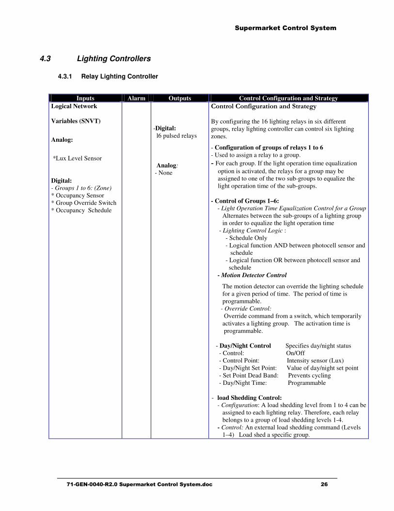
Inputs Alarm Outputs Control Configuration and Strategy Logical Network

Variables (SNVT)

Analog:

*Lux Level Sensor Digital: - Groups 1 to 6: (Zone) * Occupancy Sensor * Group Override Switch * Occupancy Schedule

-Digital: l6 pulsed relays Analog: - None

�)*'+),��)*-$%.+/'$)*�/*0��'+/'1%2� By configuring the 16 lighting relays in six different groups, relay lighting controller can control six lighting zones.

- Configuration of groups of relays 1 to 6 - Used to assign a relay to a group. 3�For each group. If the light operation time equalization

option is activated, the relays for a group may be assigned to one of the two sub-groups to equalize the light operation time of the sub-groups.

- Control of Groups 1–6: - Light Operation Time Equalization Control for a Group Alternates between the sub-groups of a lighting group

in order to equalize the light operation time - Lighting Control Logic : - Schedule Only - Logical function AND between photocell sensor and schedule - Logical function OR between photocell sensor and schedule - Motion Detector Control

The motion detector can override the lighting schedule for a given period of time. The period of time is programmable.

- Override Control: Override command from a switch, which temporarily

activates a lighting group. The activation time is programmable. - Day/Night Control Specifies day/night status - Control: On/Off - Control Point: Intensity sensor (Lux) - Day/Night Set Point: Value of day/night set point - Set Point Dead Band: Prevents cycling - Day/Night Time: Programmable - load Shedding Control:

- Configuration: A load shedding level from 1 to 4 can be assigned to each lighting relay. Therefore, each relay belongs to a group of load shedding levels 1-4.

- Control: An external load shedding command (Levels 1–4) Load shed a specific group.

������ ������ ��������� �

����������������������� ������ ��������� ����������������������������������������������������������������������

4.3.2 DimLight Controller (MT 504) �

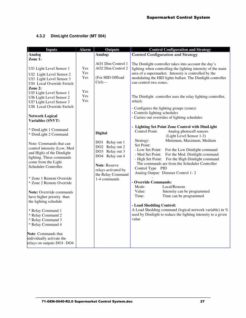
Inputs Alarm Outputs Control Configuration and Strategy Analog Zone 1:

UI1 Light Level Sensor 1 UI2 Light Level Sensor 2 UI3 Light Level Sensor 3 UI4 Local Override Switch Zone 2: UI5 Light Level Sensor 1 UI6 Light Level Sensor 2 UI7 Light Level Sensor 3 UI8 Local Override Switch Network Logical Variables (SNVT) * DimLight 1 Command * DimLight 2 Command Note: Commands that can control intensity (Low, Med and High) of the Dimlight lighting. These commands come from the Light Scheduler Controller.

* Zone 1 Remote Override * Zone 2 Remote Override Note: Overrride commands have higher priority than the lighting schedule * Relay Command 1 * Relay Command 2 * Relay Command 3 * Relay Command 4

Note: Commands that individually activate the relays on outputs DO1- DO4

Yes Yes Yes

Yes Yes Yes

Analog: AO1 Dim Control 1 AO2 Dim Control 2 (For HID Offload Ctrl)–– Digital DO1 Relay out 1 DO2 Relay out 2 DO3 Relay out 3 DO4 Relay out 4 Note: Reserve relays activated by the Relay Command 1-4 commands

�)*'+),��)*-$%.+/'$)*�/*0��'+/'1%2� The Dimlight controller takes into account the day’s lighting when controlling the lighting intensity of the main area of a supermarket. Intensity is controlled by the modulating the HID lights ballast. The Dimlight controller can control two zones.

The Dimlight controller uses the relay lighting controller, which:

- Configures the lighting groups (zones) - Controls lighting schedules - Carries out overrides of lighting schedules - Lighting Set Point Zone Control with DimLight Control Point: Analog photocell sensors (Light Level Sensor 1-3) Strategy: Minimum, Maximum, Medium Set Point: - Low Set Point: For the Low Dimlight command - Med Set Point: For the Med. Dimlight command - High Set Point: For the High Dimlight command The commands are from the Scheduler Controller Control Type PID Analog Output: Dimmer Control 1- 2

- - Override Commands: Mode: Local/Remote Value: Intensity can be programmed Time: Time can be programmed - Load Shedding Control: A Load Shedding command (logical network variable) in % used by Dimlight to reduce the lighting intensity to a given value

������

������ ������ ��������� �

����������������������� ������ ��������� ��������������������������������������������������������������������-�

661*0$71(�

������ ������ ��������� �

����������������������� ������ ��������� ��������������������������������������������������������������������.�

���� 1 �����&� ��������� ������(�&2���&� ������ �1 �����&� ��������� ������(�&2���&� ������ �1 �����&� ��������� ������(�&2���&� ������ �1 �����&� ��������� ������(�&2���&� ������ �����

1.1 Purpose of a Supermarket Refrigeration System ����������C�������'��������%��������&��������������5

• �������'�������! �����'��������� ���������� ����"��������%������������� ����������'����� �����S

• �� �������� �� ������! ����������� �� ��! �����'� ����� �� �����'����� ����� ���� ����������$���� �����

��� �����'� ����������� �� ��� ���� �� ��� ��! �����'� ����� �� �����'����� �����$���������� ��' �� ��� �%������� ������� ��"!�"�!�& !������$���!��� ������ �����������$�������������������'��

Types of Products Temperature (°°°°C) Temperature (°°°°F) �/(1�261(�

Vegetables, fruits, flowers Meat, seafood

Dairy products, beer, soft drinks Food preparation room

2°C and higher -1.1°C to 0.0°C 1.1°C to 2.2°C 4.4°C to 7.2°C

35°F and higher 30°F to 32°F 34°F to 36°F 40°F to 45°F

Medium temperature

Deep-frozen products Ice cream, frozen food

-31.7°C to -26.1°C -37.2°C to -31.7°C

-25°F to -15°F -35°F to -25°F

Low temperature

1.2 Operation and Type of Refrigerated Cases

������� �������� �� �����'����� ������� �� ���!�%��� ������ ���� �!����� ��� ����!%�������������%����!��������C���������,������'����� �����������'����� ����������!���� "��� �������!!�&��'��������5

• �"�!��%��������$���� ���� ����'�����!���• �"�!��%�����&������� ���E��!��%������������!��:�'�����!#����������$���!�%����������'����� �����5

• �����'����� ������E����� &���'!��� ����• &�!!��%�������'����� �����• ��!�� ��C�����'����� �����• �����'����� ���!�%�����5������ / �!��������������/��� %��� ����!�

������ ������ ��������� �

����������������������� ������ ��������� �������������������������������������������������������������������$��

���!�&�������������� $��%�!�&�����������������'����� ���������"� ������� �����'�!��"���� �� ����$� ����� �������������!��� �� ��� �$����������� ����!� �� ������� ��%�������������C������������'���"������� ����� ��������&�%�5

• *�! !�E�� �����'����������!������������� ������$���������� ����!�������!�������������������$����������������

• *�! !�E�� �����'����������!������������� ������$���������� ���'���������!��� ������$��������

• ��������������#��! !�E�� �����'����������!�����������!%������ �� �����"������� �����������$��������

�����������

1.3 Thermodynamic Principles of Refrigeration ��� ��������' �%�!� ��� � �����'������� �%���� �� "��� �� ��� �&� ��!!�&��' ��%�����������!��5

� ������� ��!&�%������������������������! ��������� :����!��������������'��������������#�����!����&�!!�!�����������6�������� ���'�7

CMP 1

CMP 2

CMP 3

CMP 4

Refrigeration System

V

V

V

V

V

V

V

V

Condenser

Suction Manifold

Hot Gas Supply Manifold

Discharge Manifold

EvaporatorCase #1

Other Cases

Circuit#1

Other Cases

Circuit# 2

Circuit# X

Heat Reclaim

Liquid Supply Manifold

Gaseous Coolant

GaseousCoolant

LiquidCoolant

Gaseous Coolant

EPR-RefrigValve

EPR-RefrigValve

EPR-RefrigValve

DefrostValve

DefrostValve

Defrost Valve

MainDefrostValve

Heat Exchange Valve

RACK

A

CD

Expander

HVAC System

B

������ ������ ��������� �

����������������������� ������ ��������� �������������������������������������������������������������������$��

1.4 Refrigeration System Components and Functions �:������'����"�$�#����������������� ���� ���� "�(������������������������������'����������C������'����������C���������!!%!����� ��������������!����"���� ��� ��������C��� ��� ��! !�E�� �����'����� �� ��� �����'������� ���C �� �� �� ��������'����� ������� ����������� �� �����������C��"% ��� ��� ���� ��!!� "�"���� :�'�����!# � ��������C�� ��� �&� �����'������� ���C�� ���� ���C ��� ��� �� �� ���+1-+$%1+/'$)*�7$+7.$'(4��������)*1�')�'1*�+1-+$%1+/'10�7/(1(�61+�7$+7.$'�

�����������'����������������������'����������C ���� �������%������� �������������"������ ����������'����� �����������������'�����������������C ���� ��������������@���������������������'�����������������������! �:�'�����!#������C�����!������� ����!!�&�5

�/51�)-��

�/79�

1561+/'.+1�:°°°°�;�

�.7'$)*��/*$-),0�

1561+/'.+1�:°°°°;�

�.7'$)*��/*$-),0�

0�&����������� �-���°*���-�,°*°°°° �-.°9���.°9°°°°

�$���'������������

�-���°*���,��°* �-�°9�� .°9°°°°

�����"!�"�!�& �����"������������������� ���������"#��� ��������������5

Components Numbers Functions Compressors (CMP) 2 to

10/Rack The compressors (CMP) are at the heart of a refrigeration system: They help circulate the refrigerant throughout the system. They increase the pressure/temperature of the gaseous refrigerant at the condenser inlet. The number and power rating of compressors in a refrigeration system depend on the refrigeration system load, i.e., the number of refrigerated cases connected to the system.

Condenser 1/Rack The condenser is located on the supermarket roof. It transfers to the ambient air the heat absorbed by the refrigerant during its passage in the evaporators of the refrigerated cases. This heat transfer process is based on the fact that the temperature of the gaseous refrigerant at the condenser input is at a higher temperature than the ambient temperature. (Principe 1). In addition, during this process, the gaseous refrigerant at the condenser input is transformed into liquid refrigerant at the condenser output.

Circuits 10 to 40 / Rack

Conduits between the mechanical room and the main area of a supermarket, which are used to transport:

• Cold liquid refrigerant during the refrigeration cycle. • Hot gas during the defrosting cycle.

������ ������ ��������� �

����������������������� ������ ��������� �������������������������������������������������������������������$��

Components Numbers Functions Defrost Valve 1/Circuit During the defrosting cycle:

• The defrost valve is open and allows hot gas from the hot gas supply manifold flow into the circuit to defrost the refrigerated cases.

• The refrigeration valve is closed. The frequency for defrosting a circuit is based on a programmed schedule. The defrosting schedule is programmed so that one or two circuits are defrosted simultaneously depending on the load of each circuit (number of refrigerated cases on the circuit and their temperature).

Refrigeration Valve 1/Circuit During the refrigeration cycle: • The refrigeration valve is open and lets cold liquid circulate

in cases connected to the circuit. • The defrost valve is closed.

EPR Valve 1/Circuit The EPR valve is used to adjust the refrigerated cases temperature (evaporators) connected to a circuit.

Main Defrost Valve 1/Rack The main defrost valve is opened during hot gas defrosting in one of the circuits. Opening the valve creates differential pressure, which lets hot gas circulate in the defrost circuit(s).

Hear Reclaim Valve 1/Rack When this valve has been activated, the warm gas from the discharge flows through the heat reclaim system located in the main conduit of the HVAC system. This heats the air circulating in the main conduit of the HVAC system. This valve is activated following a heating or dehumidifier request from the HVAC control system.

Suction Manifold 1/Rack During the refrigeration cycle, the suction manifold receives, via each circuit, the gaseous refrigerant from the refrigerated cases. The suction manifold is used to supply the compressors with refrigerant.

Discharge Manifold 1/Rack The discharge manifold is connected to the compressor discharge. The compressors compress the gas refrigerant in the discharge manifold at a very high pressure/temperature.

Liquid Supply Manifold

1/Rack The liquid supply manifold receives the liquid refrigerant from the condenser. The liquid supply manifold is used to supply the refrigerated cases by cooling the liquid in order to lower the temperatures of the refrigerated cases.

Hot Gas Manifold 1/Rack The hot gas manifold is fed by the compressor discharge manifold. During a defrosting cycle, the defrost valve is open and supplies the defrost circuit with hot gas to defrost the refrigerated cases.

������ ������ ��������� �

����������������������� ������ ��������� �������������������������������������������������������������������$$�

Components Numbers Functions Evaporator 1 to

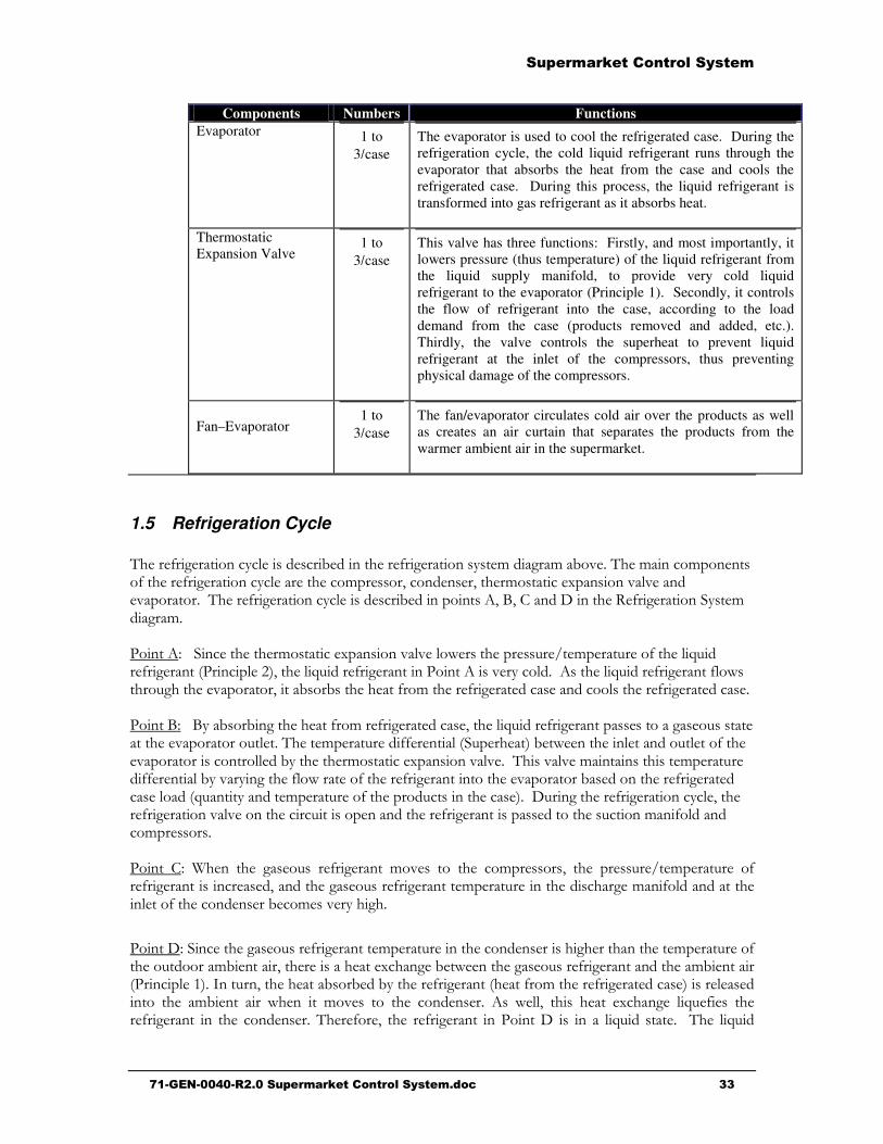
3/case The evaporator is used to cool the refrigerated case. During the refrigeration cycle, the cold liquid refrigerant runs through the evaporator that absorbs the heat from the case and cools the refrigerated case. During this process, the liquid refrigerant is transformed into gas refrigerant as it absorbs heat.

Thermostatic Expansion Valve

1 to 3/case

This valve has three functions: Firstly, and most importantly, it lowers pressure (thus temperature) of the liquid refrigerant from the liquid supply manifold, to provide very cold liquid refrigerant to the evaporator (Principle 1). Secondly, it controls the flow of refrigerant into the case, according to the load demand from the case (products removed and added, etc.). Thirdly, the valve controls the superheat to prevent liquid refrigerant at the inlet of the compressors, thus preventing physical damage of the compressors.

Fan–Evaporator

1 to 3/case

The fan/evaporator circulates cold air over the products as well as creates an air curtain that separates the products from the warmer ambient air in the supermarket.

1.5 Refrigeration Cycle

��������'��������%�!��� �����"� ����������'��������%���� ��'����"�$�����������������������������'��������%�!�����������������#��� �����#�������������(�������$�!$��� �$�����������������'��������%�!��� �����"� ���������#;#*�� �����������'�������3%���� ��'����=�����53��������������������(�������$�!$�!�&��������������@����������������!�E�� �����'�����6=������!��7#���!�E�� �����'�������=�������$��%��! ������!�E�� �����'������!�&������'�����$��������#���"���"��������������������'����� ������ ���!���������'����� �����=����;5;%�"���"��'����������������'����� ����#���!�E�� �����'��������������'�����������������$�����������!����������������� ����������!63��������7"��&��������!���� ���!��������$����������������!!� "%����������������(�������$�!$������$�!$������������������������� ����������!"%$��%��'����!�&��������������'�������������$��������"��� ����������'����� ����!�� 6E������%�� ������������������� �������������7������'��������'��������%�!�#��������'�������$�!$��������������������� ��������'������������ ������������������! �� �������������=���� *5 ?��� ��� '������ �����'����� ��$�� �� ��� �����������# ��� ��������@����������� �������'��������������� #�� ���'�����������'��������������������� ������'�������! �� �������!���������� �����"������$��%��'���

=�����53�������'�����������'������������������������ ���������'����������������������������� �����"�������#�������������(����'�"��&������'�����������'������� �����"�������6=������!� 7�:�����#��������"���"� "%��������'�����6����������������'����� ����7����!���� ���� ��� ��"���� ��� &��� �� ��$�� �� ��� ��� ������ �� &�!!# ���� ���� �(����'� !�E������ ��������'������� ��� ��� ���������������# ��� �����'�������=���������� !�E�� ������ ��� !�E��

������ ������ ��������� �

����������������������� ������ ��������� �������������������������������������������������������������������$��

�����'����� �� ��� ���!�� �� ��� ��� ����� �� ����� �� ��� !�E�� ����!% ������! �� �� ����������������(�������$�!$��� ��������'��������%�!��������!!�$���'�����

1.6 Defrosting Cycle �

�����'��� ��������'�%�!�#�������� ������$�!$��������� ����������D��=�������'�������$�!$��� �!��� � ��� ��� '�� �����'����� �� ��� ������ ����!% ������! ���� ��� ���������� ������������! �� �����!��� ���� ��� �����'����� ���� �$��������� �� ��� ������ �������S ���� ��������� �����������$����������3��������$������������$��%��! #���'�����������'�����"������!�E�� �� ���������!�E�� ����!%������! �

1.7 Heat Reclaim Exchanger

��� ���� ���!��� ���� �� !����� �� ��� ���� ��� ��� �� ��� 2��*�%����� 9�!!�&��' � ���� �� ����� ��������� ��E����# � ��'��! �� ���� ���� ��� 2��* ������!!�� �� ��� 3������ ��������������!!��� ��� 3������ �������� ������!!�� ����� ��� ���� ���!��� $�!$�# ���"!��' ��� ��� '�������'���������� ������'�������! �����������'�����������!���$�!$������#������#����������������!����'������������ ��������2��*�%������

������ ������ ��������� �

����������������������� ������ ��������� �������������������������������������������������������������������$+�

���� 1 �����&� ���)�������� ����34��������1 �����&� ���)�������� ����34��������1 �����&� ���)�������� ����34��������1 �����&� ���)�������� ����34�������� ����

2.1 Purpose of the HVAC System

���������C��2��*�%��������&��������������5

• ��������!������������������������� ���������!F��������������������� ����������������"!�

• ��������!������� ��%��������������������������C��������������� ���� ��%��������������� �����!���#����������!!� "% ��������������� ����������������C���5

• �"�'���2�� !��)���6�2)7

• >������������ �� �������������6��)7

• ����!=�������6�=)7������������� ���� ��%�� ���!��!�����$����� � ��� ��!���#���������!!� �� ��������&�%�5

• >������������ �� �������������&�������!%��� ���������� ��������F����S��

• ������������������ ���"�(�����������������!F�������������������&�!!"���� �� �����"���&���2��*�%����&��C�5

9:�)���� ����� �(

Roof-Top Unit

RAT

OAF MAT

OAD

FAN DX

HR HT

Roof

Air outlet of a

supermarket

Outdoor air inlet

LegendSPT : Space Temperature O AT: O utdoor Air Temperature O AF: O utdoor Air Filter H T : Heating Tiers(?)

RAT: Return Air Te mperature SPH : Space Humidity FAN: Fan O AD : O utdoor Air Damper

M AT: Te mpérature mélange O AH : Humidité extérieure DX: Cooling stages(?)

SA T: Supply Air Tem perature FNS: Fan Status H R: H eat Reclaim

SAT

SPT

SPH

Indoor sensors

FNS

Superm arket air return

OAH

OAT

Outdoor sensors

������ ������ ��������� �

����������������������� ������ ��������� �������������������������������������������������������������������$,�

2.2 Mechanical Components of Roof-Top Units

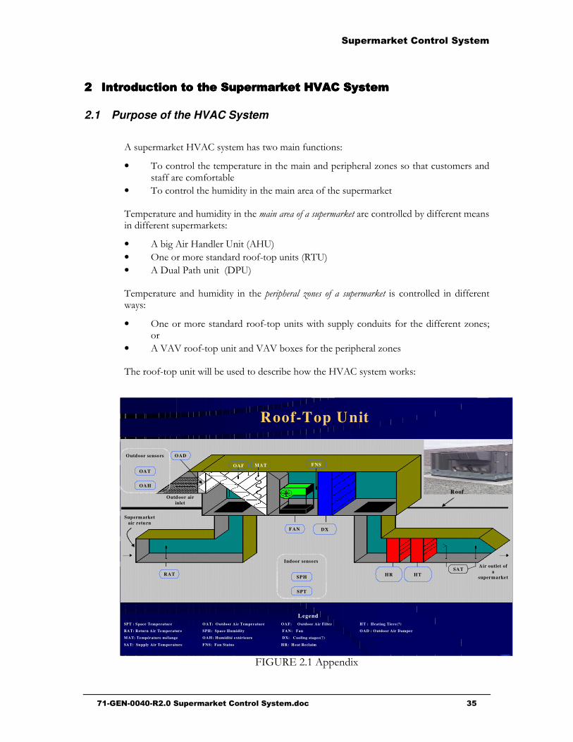
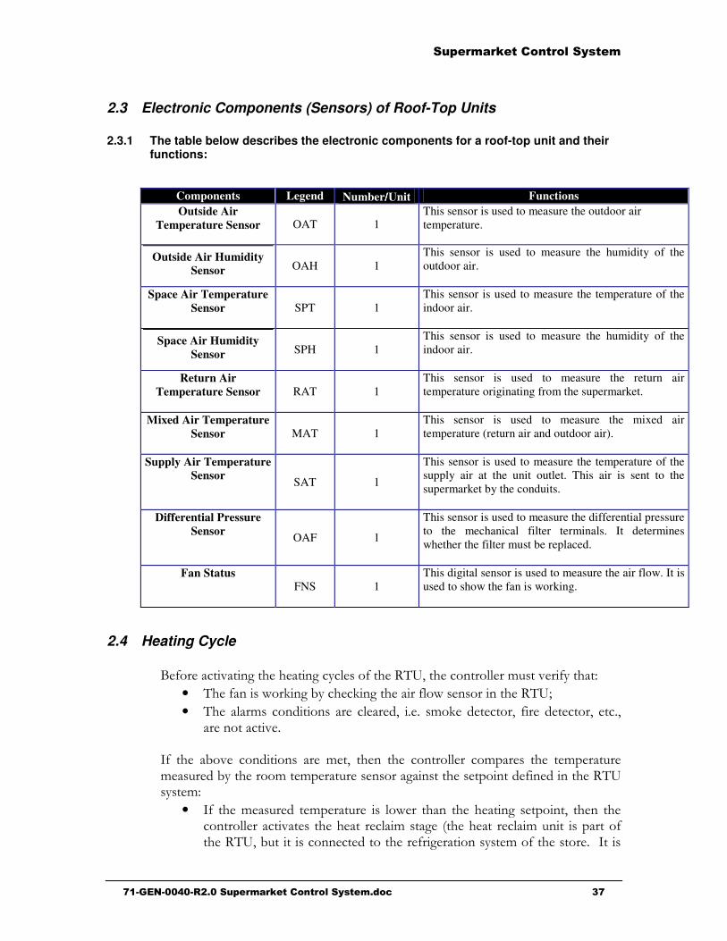
2.2.1 The table below describes the mechanical components for a roof-top unit and their functions:

Components Legend Number////Unit Functions Outdoor Air Damper

OAD

1

This damper lets fresh air enter the unit in order to improve the air quality in the supermarket. This damper is open during the day and closed at night.

Mechanical Air Filter

OAF

1

This filter traps dust from the outdoor air and return air of the supermarket. A pressure differential detector installed the filter terminals detects whether the filter must be replaced.

Fan

FAN

1

The fan circulates air through the air treatment units: cooling unit, heat reclaim unit and the heating coil.

Cooling Unit

DX

1 to 6

The cooling unit (refrigeration system evaporator) has one or more stages depending on the cooling load.

Heat Reclaim Unit

HR

1 to 3

The heat reclaim unit recovers the heat from the refrigeration system. Instead of the condenser releasing heat to the outside, this heat is recovered in the heat reclaim unit to heat the supermarket.

Heating Unit

HT

1 to 6

The heating unit has one or more stages depending on the heating load. The heating unit can be gas or electric.

������ ������ ��������� �

����������������������� ������ ��������� �������������������������������������������������������������������$��

2.3 Electronic Components (Sensors) of Roof-Top Units

2.3.1 The table below describes the electronic components for a roof-top unit and their functions:

Components Legend Number////Unit Functions Outside Air

Temperature Sensor OAT 1 This sensor is used to measure the outdoor air temperature.

Outside Air Humidity Sensor OAH 1

This sensor is used to measure the humidity of the outdoor air.

Space Air Temperature Sensor SPT 1

This sensor is used to measure the temperature of the indoor air.

Space Air Humidity Sensor SPH 1

This sensor is used to measure the humidity of the indoor air.

Return Air Temperature Sensor RAT 1

This sensor is used to measure the return air temperature originating from the supermarket.

Mixed Air Temperature Sensor MAT 1

This sensor is used to measure the mixed air temperature (return air and outdoor air).

Supply Air Temperature Sensor SAT 1

This sensor is used to measure the temperature of the supply air at the unit outlet. This air is sent to the supermarket by the conduits.

Differential Pressure Sensor OAF 1

This sensor is used to measure the differential pressure to the mechanical filter terminals. It determines whether the filter must be replaced.

Fan Status FNS 1

This digital sensor is used to measure the air flow. It is used to show the fan is working.

2.4 Heating Cycle

;���������$����'���������'�%�!���������)#���������!!������$����%����5

• ��������&��C��'"%����C��'�������!�&�������������)S

• ����!������� ��������� �!���� #�������C� �������# ���� �������#����#����������$��

:� ��� �"�$� ��� ������ ��� ���# ���� ��� ������!!�� �������� ��� ������������������ "%�������������������������'���������������� ����� �������)�%����5

• :� ���������� ������������� !�&�� ���� ���������'��������# ���� ���������!!������$��������������!������'�6����������!��������������������)#"�������������� ����������'��������%���������������:���

������ ������ ��������� �

����������������������� ������ ��������� �������������������������������������������������������������������$-�

����� ��� ���J����������'���'�K7� :� ��� ���������"��&��� ���F���������������� ����������������!!��'�#�� �������������"!������������������� $�!�� &��� ��� ���� ���!��� ���'� ��!%# ���� ��� ������!!�� &�!!'�� ��!!%����$��� ��� ������������'���'��6�!�������! �� '��7 ����! ������������������� S

• :� ���������� �������������'�������������������'��������#�������������!!��&�!!'�� ��!!%���� �&�����!�������!6��'��7������'���'������!��� �������� �� ������ � :� ��� ���� ����������� �� ���!! ��� ��'�# ���������!!��&�!!���� �&�����������!��������

2.5 Dehumidification Cycle ������� ��%������������������������C�������G����������:�������� ��%�����"��! ��'�����������!!� ���������!%#�����&�!!"��! ������������'����� ��� ���!�%�����D�$���������#��������!���'��������������������E����%����� �������%�!�������!�� ��� ����������������5

• :�������������'%�����������S

• ������������������ E��!��%����������'����� ������

;�������� ����� ������%�!�������$��� #���������!!������$����%����5

• ����������"%����C��'�������!�&�������������)S

• �!! �!���� ��� ��������� �!���� #���� �(�����$�!% !�& ������������� ������!��'���!#���� �������#����#����������$��

:� ��� �"�$� ��� ������ ��� ���# ���� ��� ������!!�� �������� ��� ���� ��%������� "%�������������������������'���������������� ����� �������)�%����5

• :� ���������� ���� ��%����'��� ���� ������� ��%��������# ���� ���������!!������$���������������'������!��'�:���� ���������"��&������������� ���� ��%�� ����������������!!��'�#�� �������������"!�������� ��� �������� $�!�� &��� ��� ����� ���'� �� ���!��' ��!%# ���� ���������!!�� &�!! '�� ��!!% ����$��� ��� �� ���� ���!��' ���'�� ����! ������������������� � �����' �����%�!�# ���&������������ �� ������&�!!��� ������ ��� ��������� ��� ���!��' ���!��� &�!!"� ���������� ��� ��������S

• :� ��� ������� ���� ��% �� !�&�� ���� ��� ���� ��% ��������# ���� ���������!!��&�!! '�� ��!!%���� �&� ��� ���!��'���'������! ������������������� �

���� ����� ����������%�!����!���������������������������������C���� ���! ����� ������������������������������#������������������ �����������'���"�!�&����������������������#���������!!������$��������������!������'��������������>����������'���'�����"�����$��� ��&�!!#�� �����"� ����������++)+<��1-1+1*71�().+71�*)'�-).*0��++)+<��1-1+1*71�().+71�*)'�-).*0�#����'��++)+<��))95/+9�*)'�01-$*10����� ����� ����������%�!��� ���������'�%�!������ ���� ���������������������

������ ������ ��������� �

����������������������� ������ ��������� �������������������������������������������������������������������$.�

2.6 Air-Conditioning Cycle ������������!F���������������C��6�������#���������#"��������#����7���! "�#��������������#������ ������ ���������!�%�����������;�����������!��'�%�!�������$��� #���������!!������$����%����5

• ����������"%����C��'�������!�&�������������)S

• �!! �!���� ��� ��������� �!���� #���� �(�����$�!% !�& ������������� ������!��'���!#���� �������#����#����������$��

:� ��� �"�$� ��� ������ ��� ���# ���� ��� ������!!�� �������� ��� ������������������ "%�������������������������'���������������� ����� �������)�%����5

• :����������� �������������'����������������!��'��������#�������������!!������$���������������'������!��'�:���� ���������"��&������������� ������������� ����������������!!��'�#�� �������������"!��� ����� �����������$�!��&��� ��� ��������'� �� ���!��' ��!%# ���� ���������!!�� &�!! '�� ��!!% ����$��� ��� �� ���� ���!��' ���'�� ����! ������������������� S

• :� ���������� ������������� !�&�� ���� ��� ���!��'��������# ���� ���������!!��&�!! '�� ��!!%���� �&� ��� ���!��'���'������! ������������������� �

������ ������ ��������� �

����������������������� ������ ��������� ����������������������������������������������������������������������

$$$$ 1 �����&� ���)��!&2)& 2������1 �����&� ���)��!&2)& 2������1 �����&� ���)��!&2)& 2������1 �����&� ���)��!&2)& 2������ ����

3.1 Description of a Lighting Control System 9�'���*� �!!������������������������������������C��!�'����'�%�����

Zone 1

Circuit#1

Circuit#2

Circuit#3

Lighting Controller

Power DistributionSystem

Circuit#4

Circuit#5

Circuit#6

Zone 2

Zone 3

ElectricConnection

Light Fixture

$%.+1�����"��$%&'$*%��2('15�)-�/��.61+5/+91':����������C��# ��� !�'����'�%�������� ����� !�'�� ��(�������'���F� ���� !�'����'F������!! !�'����'������������������� ���!�'����'������!!��������!!�&��'�����������$� � ���� ����! �"��� ��� !�'����' F���� �� !�'����' �%���� ���������� �� ���������C���

����"��$%&'$*%�#)*1(������ ����� �� �������������������C����� �$� � ���� !�'����'F����� �F������"� �!����� "%����$������������%����!�������$��"%�!�'���!'����6 �������$�!�'����'7��!�'����'F������"������!!%������������!!%������!!� �

������ ������ ��������� �

����������������������� ������ ��������� ����������������������������������������������������������������������

��� ��"!�"�!�& �����"�� ��� ��������F���� ������� ���� �����������C��� *������F���� ���"���" �$� � ������"�F����6!��� ��!���7# �������$� ��'����'������� �%����������'�!�(�"�!��%�

0������� 0�'����'H��� 3�"�H���

�.'0))+� =��C��'!�� <��

3�'��

�������!����

)�!�� ��'F���

�*0))+� 3�!������ <��5���!��#��������&�%#�����������

�����'����� ����� <��5;��� �� ����������� ����

��������$�!�'����' <��5;��� ����� ���'�����

3��$������� <��5;��� �����������!���$����

����'���%!�'����'

>��������� <��

���������!����

3����'�����

/=,1�����"��$%&'$*%�#)*1(�)-�/��.61+5/+91'����������������"��� �"��&��������F����!�'����'F����� ����������!�'����'�%����� 3��!! !�'����'F����������� �(�����$�6�E��������� �����!!����� �����7#"������������!�(�"�!��%�� '��������������!����� ����'�%������������'������

����"��)56)*1*'(�)-�'&1��$%&'$*%��2('15��������������������!�'����'�%�������������� �%�����!�'����(�������!�'����'������ ������ !�'���������� ����� ��� �����"����' !�'��#��%����!!%���������' ��� !�'�������� �� �!�������!!% ���������' ��� !�'�� ������� � !�'�� ��(���� �� �� � �� �� �����!!�&��'�����5

• �$%&'�().+715=�� �������!�'��• �)791'�'.=152�! ����!�'�������������������'�� �!�������!!%�����������!�'��������

• �/,,/('5��$��������������!���������!�'������'���������% ������'�62:�7!�'���:����$� ���������'$�!��'�&��!����"�!�F��'���������� ����'�������������������&��%��������!�� �5��'�����"�!!������ �!��������"�!!����

• �1-,17')+5���!�������!�'��• �1*(5�� ����������������������!�� ��� �����$��'����!�'��• �).($*%4����������!�������������! ���'������!!����������!�'����(����

������ ������ ��������� �

����������������������� ������ ��������� ����������������������������������������������������������������������

������"��$%&'(���������� �%����� !�'�������$��!�"!�#������$��' ������&������������������������������!!�&��'��������������������� ��� �����"��'�!�'��5&����'� �(� ��������������� �������������$���'�!������!�'��

�������:����(������ ��������� �"���"�( ��������������� ��������������!���������"��&���

���!�'���!�(����� �� ����'%������� �:����(������ ��!��������&����

���������%( ����!������������������!����� ��� �����"G���"%�

��������� !�'�� ������� ���� ���!� �� ������� ����������'���!�&��!���� �(����������!�����"G���������������!�

���������� ��)� � ����( �����! ������� ���"�"�!��% ��������� ��� ��������'� ��

����!� &����� ��������"!� &��� ��� !�'����'��� '�$�������� � ������� ���"�"�!��% �� �� !���� ��R ���������� � ������� ����������!��$����������

3�������C������������%����� !�'���������5 ����� ������#�!����������� 2:����"!�*�-� �����"��������������������������������������%�����!�'����������

261(� �.=3261(� �&/+/7'1+$('$7(�

3��� �� • 0�&���������%58����!�����• 3����!���5�.�A�.�������• ���!��������5������!

�*7/*01(71*'�

���'�����2�!�'�� • ��������������������� �� !�'���������• 0��'��!����������� �� !�'���������• 0�'��"�������������������� ��������

0��� �'�� ����������������%����������������������� ������!�'���������

• 0�'������������!�������� �� !�'���������• ���!��������5����!�%#�����'!�'����'

,.)+1(71*'� • 2�'����������%• ��� !�'����' �����"������� ��������• 0��'!���• ���!��������5*�����!%��� ���������!!%

������ ������ ��������� �

����������������������� ������ ��������� ��������������������������������������������������������������������$�

261(� �.=3261(� �&/+/7'1+$('$7(�

������%$���� • ���!�����������$����!!2:�!�'���• 1���C �'�� ����������������%• ���%&��C��!���� �(• 0��'!���5��#���Q�����• ;!���'����!�'��• ���!��������50�� ������'!�'����'

2�!� �!�'��� • ?� ����'���&����'������'�5-�A����&����• ���������%5.��� .!��������&���• ��� ��!���� �(• 0���5

• 0�&��&��5�#.�������• 2�'���&��5 .#���A��#��������

• ���!��������5• :� ���5�����#��� ���#�� �������#����• >�� ���5=��C��'

2�'������������ ���

• �������������������!� �!�'���• 0�&��!���� �(• ��! ��!��� !�'��• ���!��������5:� ������!�� ��� ����

�$%&�$*'1*($'2�0$(7&/+%1�:���;�,$%&'�

0�&����������� ���

• ;������������%���!!2:�!�'���������• 0�&��!���� �(• ������������!��• ���!��������5

• >�� ���53������%�� ������!�'����'• :� ���5?�����!����������������

:�'�����!#�����������%�����!�'��������������� ����������C���5

• :���� ������!�'��������� ����������F����#�������������������� "��� #��������&�����!����

• 2�!�'��!�'������!����� �� �������$�!�'����'�• 9!��������� !�'��� ��� �������!!% ��� ��� '�����! !�'����'5 ��!�� �����# �������#�����'�&�%�� ���%����!����� ��������������!��������5����F�������#�������� $�'���"!���������

• 2:� !�'��������� ��� !��'���������5 ��!�������#���C��'�����#��!�� ��'�����#�����

����%���� ���"����!�'����(����������������C�������!���� ��������������!�$�!�� �����!�����������������"��� ��������������!������������ ���C����'�����&������� �������� ��������������!���:���������#��$��'����'%�������������%�

������ ������ ��������� �

����������������������� ������ ��������� ����������������������������������������������������������������������

3.2 Configuring Lighting Controls ��%����!!�'����'������!���!� ���!�'����'������!!��#&����������!�!�'����'"��� ����%����! ������'%� ��� ������ �����$� ��'��!� ���� ��� ���������� ������� �� ����� ���������!!��������� ����� �%!�'������������!!������$����!�&�$�!��'���!�%�#&���������� ������$�������!������!�� ���!�%����"� �����!%�������� �����!�'����(��������$���������� �����!�'����'��������&������������������&������������ ������$�����G��!�'����'!�� ���������!"���C�����!�������������!�������������!�'����'������������ ������������'������$��!�� ��� �!���������'���

���������&��%�����!�'����'�%���������'��������#&�������������"��� �����!�'����'F����5

• 0�'����'������!�%����&�����!�%��� ����������• 0�'����'������!�%����&���!�&�$�!��'���!�%�

9�'���� *��� �� *���� �!!������� ���� �����'�������"��� �� ������!! !�'����'�%�������������'��(!�'����'�������� �$� � "��&��������F�����

Zone 1

Circuit#1

Circuit#2

Circuit#3

Zone 2

Zone 3

Circuit#4

Circuit#5

Circuit#6

BreakerPanel

Wiring

ContactorsRelay Panel

1

2

3

4

5

6

7

8

Lighting Controller

Sensors

Photocell

Occupancy

Switch

9�'���*��� A0�'����'*�����!�%����?�����!�%��� *���������

������ ������ ��������� �

����������������������� ������ ��������� ��������������������������������������������������������������������+�

:� ��� !�'����' ������!�%����&����� ��!�%��� ����������# ����F����� ����� "%���������'�!!�����������F��� �������������&��������������������������!!� "%���!�%����� $����'������������'�������������� ��������������"�������!��������!�'����'������!!���� ������"������!�%��2�&�$��#�����%����������!�%����������!�(�"!������ ����F����� �������� "��� �� ��� ������������ ��� �!�������! !�'����'��������������$��#�����%���������'���������E�����������"!��'�

:� ��� !�'����' ������! �%���� &��� !�&�$�!��'� ��!�%� 69�'��� *����7# ���� ������� ���������� ���!�&�$�!��'���!�%#&�������������� ��������!�������!�'����'������!!���0�'����' F���� ��� ����� !�'���!!% �� ��� !�'����' ������!!�� "% ����$����' ��� ��!�%���������� &����'�$��F�������������'���������������������!�(�"�!��%���������F������"�����!%�� ����� �� ��E�����!�����"!��'�������!�'����'������!�%����&�����!�%��� �����������2�&�$��#���!��'����"������!�%���E���� ��������������!!�����������

Circuit#1

Circuit#2

Circuit#3

Circuit#4

Circuit#5

Circuit#6

BreakerPanel WiringRelay Panel

1

2

3

4

5

6

7

8

Lighting Controller

Sensors

Photocell

Occupancy

Switch

Zone 1

Zone 2

Zone 3

9�'���*����A0�'����'*�����!3%����?���0�&���!��'���!�%����������!�%������%"�����"���������"��������'��������#&����������������������$��' � ��(� ���������� �� ��� ���������� �� ��� ����� �������� "���' �� �$� ��!!%�������� �� ��� !�&�$�!��'� ��!�%�������!!�&����� �!�(�"�!��% ���� ��� ��������&����&�����!�%�����'��������� �� ����������"������!�%���E���� �

������ ������ ��������� �

����������������������� ������ ��������� ��������������������������������������������������������������������,�

��� !�'����' ������! �%����� �� � "��! ��' ��% "� ������!�F� �� �����"��� �� ����"�������������&��9�'���*���-�!!������������&���������������

Centralized ControlSystem

Zone1

Zone3

Zone2

Power Distribution

Supermarket Main Area

Controller 1

Zone1

Zone3

Zone2

Controller 2 Controller 3

LonWorks Network

9�'���*���-A*�����!�F� *�����!3%����������������"��� *�����!3%����

:� � ������!�F� ������! �%����# ��� ������! ������!!�� ������!���$���! !�'����'F����� :� �����$����'��!���������������#���!%F�� ����� ����$���������!�%���������!�!!���F���������"��! ��'����������!������!!���������!!%!����� ������!�������! �����"����������������������������!��!!F����#"����E������!��'�������!!��������$��#�!!�!������!�'����'������������������� �����������!������!!��������!�������! �����"����������

:� � �����"��� ������! �%����# ��� ������! �%���� �� ��" �$� � ���� ��$���! !���!������!!��������!!� ���� ���� !�'����'F����� �����������C���������������� �����!%�������� �� ��� !���! ������!!�������� ��� ������! ������!!��� ���� !���! ������!!������ ���� ����� �������� ��������&��C���������������$�!$�����!!��������!!����� ��E����� !��� ��"!��'� ��� ��!��"�!��% �� ���� �������� ���� � �� ��� ��!� ���� �� ������&��C�

������������������������!!�&��'� $����'��5

• :��������!!���� ������$�#��!%���F���&�!!"�������� �• :������'������"��� �#��!%��������������!!���&�!!"�����'� �

2�&�$��#����'������������#���!�'����'���� �!���������F�������"��� �����"��� ������������!!���

������ ������ ��������� �

����������������������� ������ ��������� ����������������������������������������������������������������������

3.3 Lighting Control Strategy in the Supermarket

��� !�'����' ������!������'%��"��� �� �&�����������5 ������������ ��!������������ ���� ����"G����$�����5

• ��������������������������������'��� ������5���!�%�������%#��� ���E��!��%• �����$� �!�'����'�������&�������� �������� ��������������!��

9!�(�"�!��%������������������������������!!�&��'�������5

• � ��������C��D� ������' �� �!����' ����� ��% $��%# �� ������ ��� ���� ������������'!%!��'������� ����������������������������C��D�����$�����5���%������� ����� ��� �����'���� ��� �%� 0�'����' ���� "� � G���� "��� ������������������� ����%��������$��%6��'�����������"%��������� ����'��� �%$���������������"%����������������'��7�

• 3�������C��� ��� "������' !��'�� �� !��'�� �� ��� �������' ���� �� �������$���������'��� ���� ��������!������������������!�'����'�%����"%�������'��&F������������"�������!!� �� ���� ���!%�

:�'�����!#��������&������'������!������'%����'�!%��� ����������C������������!�������!%�����!���������"����'�� ��!��������!!�'����'������!#���!�'����'�����������'����� �!�������$�!%���������������'������!�'����'��(�����6'�����!!%.�R7������� ���&��!������������� ����������'%��C��&��� ���.�@.�������'%69�'���*�.� 7� :�"�!����� ��� ���� ��� !�'������ ���� ����!�����������������&��!����$� ��'� �E����!�'����'

Zone 1

Zone 2

SupermarketMain Area

RefrigeratedCases

9�'���*�.� 5.�@.�0�'����'3�����'%

������ ������ ��������� �

����������������������� ������ ��������� ��������������������������������������������������������������������-�

��"!�*�.� ���&���� ��������!�'����'������!������E���5����������������!������!�

�)*'+),�261�� �)*'+),�17&*$>.1�� �1(7+$6'$)*�/*0��)*($01+/'$)*(�

�����&������' 0�'����(���������&����� ��>�@>�������"��� ��������'����� ���� �!��:�����������!������E��# ���������%����������������� 5

• ���������!�����

• �!�������������

• =��'�����"!�����&�������������%����������!�������!� �������!������!&��������������$���� �������� �!���!�'����'��������������������������� #���!�'����'�%������������������!!%'�"��C�������&������'�� ��

*�!���#���!!��"�����5�!�������������������!������������ �����F����&���������� �!���=��'�����"!�����&��������������� ������������F����&���$����"!����� �!���

.')5/'$7�

����3&������'@�� �!�����"��� ����"����!�'����'

0�'����(���������&����� ���� �!��� ����������%"��� �������"����!�'����'!�$�!�&���������� �%!�'���

��������!!����������� �����$���$���"!���%�5

• :���� �'���!�!����������'��!���&�������������������!!��!�'����'��!�%�6�������7�

• :��� �� ���!�' �!�������� ��'��! �� �� �!��� ��� !�'����'������!!��D����!�' ���!��������� �!���� ��� !�'����'��������%"��� �����!�$�!����"����!�'���

����!�������������!!���������� ������ ������!�������������!!%�������������������������������������������������!!��������������������������!����������%������"����������������

:�'�����!#��� ����������!!��������������"���� ����� ������!��������"�����������!�&�������$��%�� �����!����� � G�������!�$�!�

*�!���#���!!��"�����5����&������'�� ������ ������ ������!����������� �!������� ������ ����� ������!��������&������������C%!�'����

������ ������ ��������� �

����������������������� ������ ��������� ��������������������������������������������������������������������.�

�)*'+),�261�� �)*'+),�17&*$>.1�� �1(7+$6'$)*�/*0��)*($01+/'$)*(�

� >���������@������������

>����������� ���������������� �'���! �$���������&�������!�'����(����� ���� ��'��&����������!�������'�$����%����!�����������

���!�'����(������������$��� &������������������ ������������������!�'����(������������� ������������'�����"!�����&���������������!�����������>�����������%"� ������ "%���� ����'��!#�!������� #������� ��������!������

*�!���#���!!��"�����(:�'�����!#!����� ��������&����!����� ��������������6������#���������!����#�!�������! �����"���������#�����'�����7���$������� �"�������������

�/*./,� 9���� *�����!&�����������

�������� ������!&���������������$����!�'����'�����!���!�&��������!�'����'�����������������'�����"!������������� �

*�!���#���!!��"�����(�9������������������������������!����� ��������� ����� ���"�������������

��"!�*�.� A0�'����'*�����!������E���� !�'����' ������! ������'% �� ��� ���!������� �� ��� �� ���� ������! ������E���� 9���(���!�#���������������������������C��#�����&�����������"���� ����'������'������� ������ ������!&���������������� ���������'��������"!�*�.������������� !�'����'������!������'����� ����� ��������������! �$������� ��� �������� !�'����'F���������������C���

������ ������ ��������� �

����������������������� ������ ��������� �������������������������������������������������������������������+��

�$%&'$*%�#)*1�

�)*'+),��'+/'1%2� �)*'+),��1?$71(�

�/+9$*%�/*0��$%*(�� • �����&������'������� �!������G�������&����&������'"��� ����"����!�'����'�

• 0�'����(���������$��� ����� ��C#���!!��'���� ����� �%!�'���

������#���'�����"!�!�'����'���� �!���� �������!!�������

+/--$7��/*1(�/*0��*,)/0$*%� +1/�

• �����&������'�!��'&����&������'"��� ����"����!�'����'�

• 0�'����(���������$��� ����� ��C�� ���!!��'������������%

������#���'�����"!�!�'����'���� �!���� �������!!�������

�1+$6&1+/,� +1/��1+?$71(�/*0��/,1(� +1/4�� $(,1(@��*'+/*718/2�/*0��/(&$1+� +1/�

• �����&������'

• 0�'����(���������� ����'���"�������������� ����� ���.�@.������������ �� ��

=��'�����"!�!�'����'���� �!��

�/,1(� +1/��$'&��*1+%2��6'$5$A/'$)*�

• �����&������'�!��'&����� �!�����"��� ����"����!�'����'�

• 0�'����(���������� �������� ���������'������� ��������%�� �!��� "��� ����"����!�'����'"��� ��������'������

=��'�����"!�!�'����'���� �!���� �������!!�������

�1-+$%1+/'10�/*0�+11A1+��/(1(�

• �����&������'

• ����$��� ����'"�������������� ��$���!���������� ���"��������������������������"���!!� ������ ��������������������

=��'�����"!�!�'����'���� �!��

�17)+/'$?1��$%&'$*%� • �����&������'

• ����$��� ����'"������������#����� ��� ����'��������� ����� �

=��'�����"!�!�'����'���� �!��

�--$71@��17&/*$7/,��))5@��')+/%1��))5�

• �����&������'�!��'&������������� ���������� ����� ������!&�����������

• ����$��� ����'"�������������� ����$��� "%��������������������������!!%����� ������

=��'�����"!�!�'����'���� �!�#���������� �������#�&����&�����������

�51+%1*72�,$%&'$*%� • *�����!!� "%���������������!�%������������ ��������'���%'���������

��"!�*�.��A*�����!3�����'%���0�'����'H�������3�������C��

������ ������ ��������� �

����������������������� ������ ��������� �������������������������������������������������������������������+��

Revision History

REV Description Revised by Date 1.0 Creation and formatting of the document, based on 71-GEN-0010

(French version) Rossion 12-sep-03

1.1 Document Revision and corrections JMT, JG, CBC

18-sep-03

2.0 Document Release JG 29-sep-03


Recommended