icroelectronic Circuits SJTU Yang Hua generators and waveform-shaping circuits Introduction 12.1 Basic principles of sinusoidal osc illators 12.2 RC oscillator circuits 12.3 LC and crystal oscillators 12.4 Bistable Multivibrators 12.5 Generation of a standardized puls e-The monostable multivibrator
Transcript
Microelectronic Circuits SJTU Yang Hua
Chapter 12 Signal generators and waveform-shaping circuits
Introduction12.1 Basic principles of sinusoidal oscillators12.2 RC oscillator circuits12.3 LC and crystal oscillators12.4 Bistable Multivibrators12.5 Generation of a standardized pulse-The monostable multivibrator
SJTU Yang HuaMicroelectronic Circuits
Introduction
The twoThe two different different approachesapproaches
(1)(1)linear oscillators:linear oscillators:
employs a positive-feedback loop consisting of an employs a positive-feedback loop consisting of an amplifier and an RC or LC frequency-selective netamplifier and an RC or LC frequency-selective network.work. (Section 13.1-3)(Section 13.1-3)
((2)nonlinear oscillators or function gener2)nonlinear oscillators or function generators:ators:
• The bistable multivibrator(Section 13.4)The bistable multivibrator(Section 13.4)
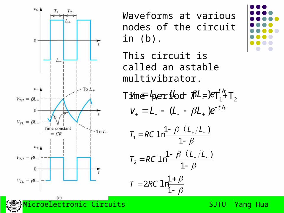
• the astable multivibratorthe astable multivibrator (Section 13.5)(Section 13.5)
• the monostablethe monostable multivibrator(Section 13.6)multivibrator(Section 13.6)
SJTU Yang HuaMicroelectronic Circuits
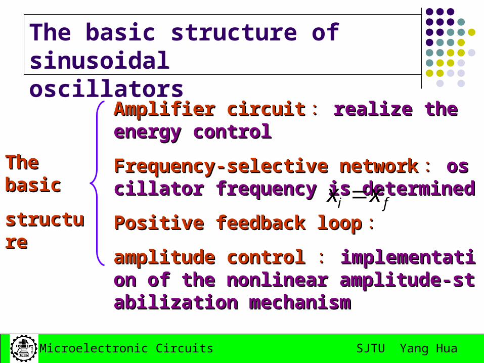
The basic structure of sinusoidaloscillators
The basic The basic
structurestructure
Amplifier circuitAmplifier circuit :: realize the energy controrealize the energy controll
Frequency-selective networkFrequency-selective network :: oscillator freoscillator frequency is determinedquency is determined
Positive feedback loopPositive feedback loop ::
amplitude controlamplitude control :: implementation of the implementation of the nonlinear amplitude-stabilization mechanismnonlinear amplitude-stabilization mechanism
fi xx
SJTU Yang HuaMicroelectronic Circuits
Basic Principles of Sinusoidal Oscillator
The oscillator feedback loop
The basic structure of a sinusoidal oscillator.
A positive-feedback loop is formed by an amplifier and a frequency-selective network.
SJTU Yang HuaMicroelectronic Circuits
Basic Principles of Sinusoidal Oscillator
Feedback signal xf is summed with a positive sign
The gain-with-feedback is
The oscillation criterion: Barkhausen criterion.
)()(1
()(
ssA
sAsAf
)
n
jjAjL
A 2
1)()()( 000
F:\Ä£µç¿Î¼þ\¶¯»\Õñµ´µÄ²úÉú.exe
SJTU Yang HuaMicroelectronic Circuits
Basic Principles of Sinusoidal Oscillator
Nonlinear amplitude control To ensure that oscillations will start, the Aβ is
slightly greater than unity. As the power supply is turned on, oscillation
will grown in amplitude. When the amplitude reaches the desired level,
the nonlinear network comes into action and cause the Aβ to exactly unity.
SJTU Yang HuaMicroelectronic Circuits
The implementation of the nonlinear
amplitude-stabilization mechanism
The first approach makes use of a limiter circuit
The other mechanism for amplitude control utilizes an element whose resistance can be controlled by the amplitude of the output sinusoid.
SJTU Yang HuaMicroelectronic Circuits
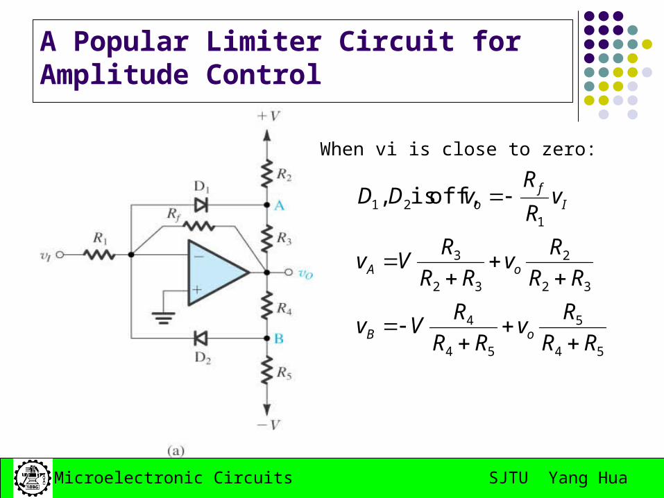
A Popular Limiter Circuit for Amplitude Control
54
5
54
4
32
2
32
3
121 off, is,
RR
Rv
RR
RVv
RR
Rv
RR
RVv
vR
RvDD
oB
oA
If
o
When vi is close to zero:
SJTU Yang HuaMicroelectronic Circuits
A Popular Limiter Circuit for Amplitude Control
3 3
2 2
4 4
5 5
1
on the contrary:
1
D
D
R RL V V
R R
R RL V V
R R
When vi goes positive,D1 is on, D2 is off
SJTU Yang HuaMicroelectronic Circuits
A Popular Limiter Circuit for Amplitude Control
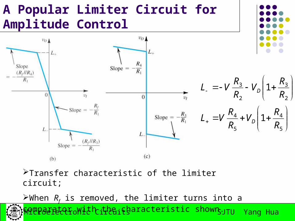
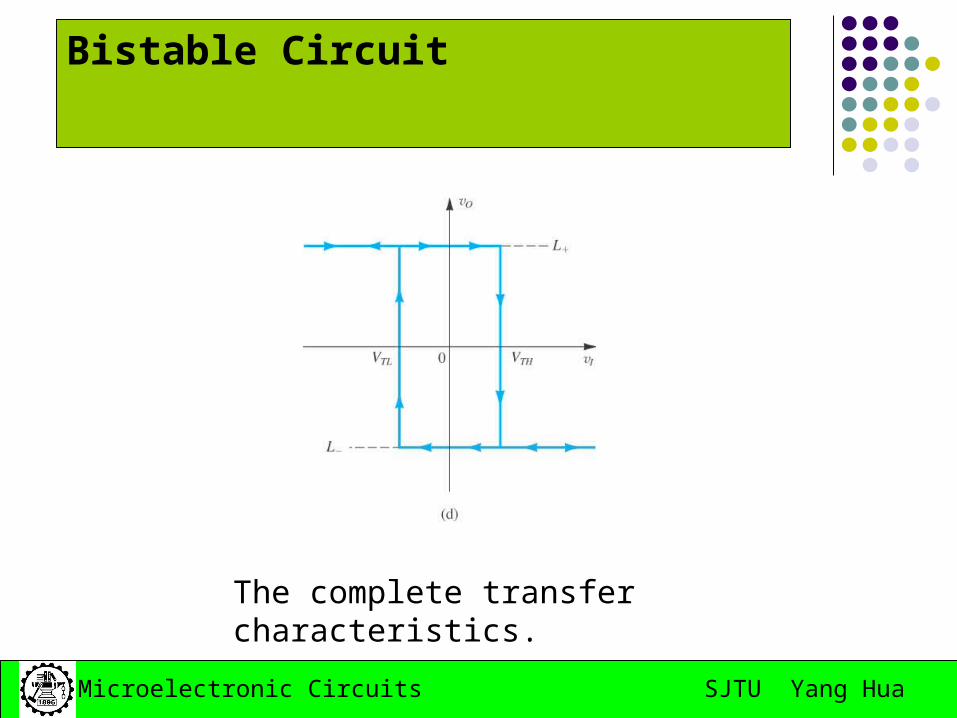
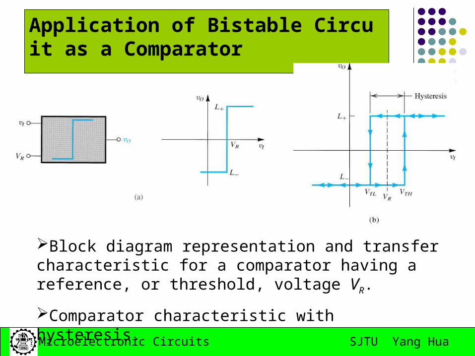
Transfer characteristic of the limiter circuit;
When Rf is removed, the limiter turns into a comparator with the characteristic shown.
5
4
5
4
2
3
2
3
1
1
R
RV
R
RVL
R
RV
R
RVL
D
D
SJTU Yang HuaMicroelectronic Circuits
Oscillator Circuits
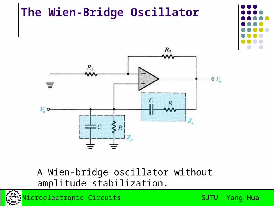
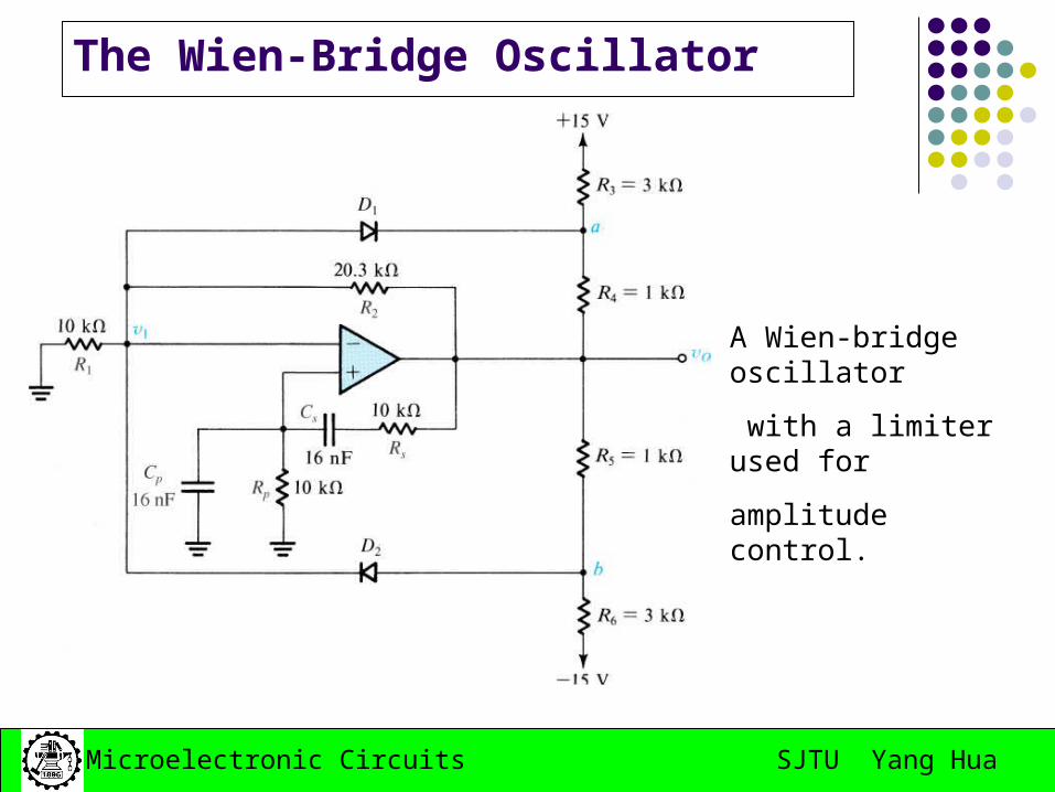
Op Amp-RC Oscillator Circuits The Wien-Bridge Oscillator The phase-Shift Oscillator


![[ Sedra] Microelectronic Circuits(b Ok.org)](https://static.documents.pub/doc/80x56/617b73ef7012c349660bd625/-sedra-microelectronic-circuitsb-okorg.jpg)


