icroelectronic Circuits SJTU Yang Hua Chapter 8 Feedback Introduction 8.1 The general feedback structure 8.2 Some properties of negative feedback 8.3 The four basic feedback topologies 8.4 The series-shunt feedback amplifier 8.5 The series-series feedback amplifier 8.6 The shunt-shunt and shunt- series feedback amplifier
Transcript
Microelectronic Circuits SJTU Yang Hua
Chapter 8 Feedback
Introduction8.1 The general feedback structure8.2 Some properties of negative feedback8.3 The four basic feedback topologies8.4 The series-shunt feedback amplifier8.5 The series-series feedback amplifier8.6 The shunt-shunt and shunt-series feedback amplifier8.10 Stability study using bode plot8.11 Frequency compensation
SJTU Yang HuaMicroelectronic Circuits
Introduction
It’s impossible to think of electronic circuits without some forms of feedback.
Negative feedback Desensitize the gain Reduce nonlinear distortion Reduce the effect of noise Control the input and output impedance Extend the bandwidth of the amplifier
The basic idea of negative feedback is to trade off between gain and other desirable properties.
Positive feedback will cause the amplifier oscillation.
SJTU Yang HuaMicroelectronic Circuits
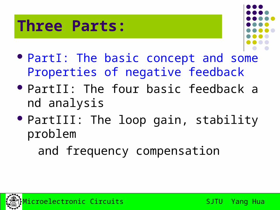
Three Parts:
PartI: The basic concept and some Properties of negative feedback
PartII: The four basic feedback and analysis PartIII: The loop gain, stability problem
and frequency compensation
SJTU Yang HuaMicroelectronic Circuits
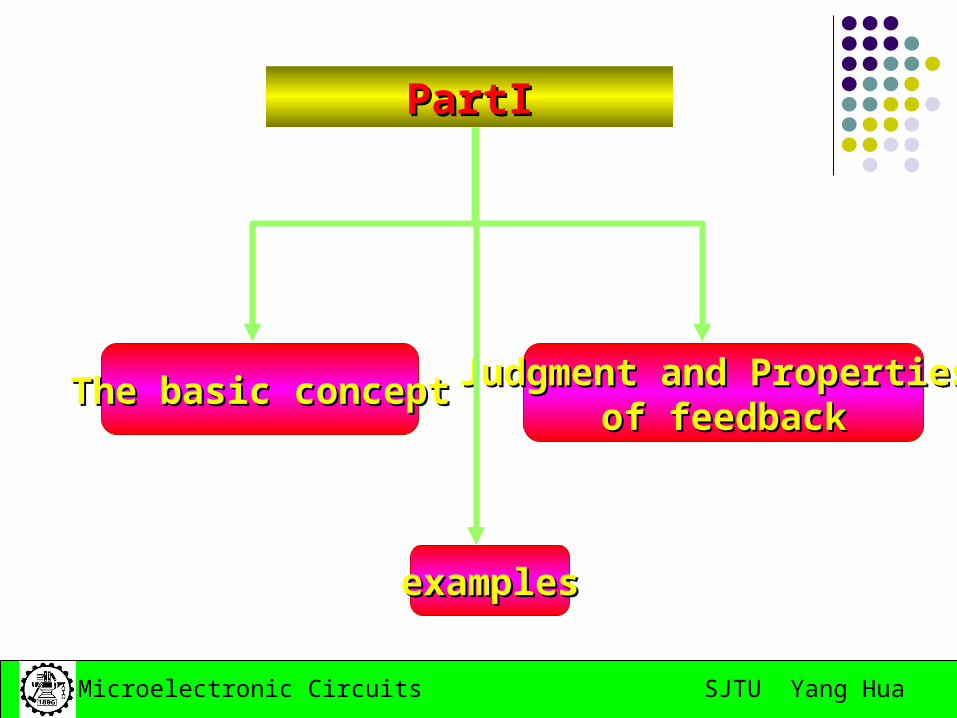
PartIPartI
The basic conceptThe basic concept Judgment and PropertiesJudgment and Properties
of feedbackof feedback
examplesexamples
SJTU Yang HuaMicroelectronic Circuits
PartI: The basic concept and some Properties of negative feedback
This is a signal-flow diagram, and the quantities x represent either voltage or current signals.
In electronic circuits, part of or all output signal is fed back to input, and affects the input signal value, which is called feedback.
8.1 The General Feedback Structure
SJTU Yang HuaMicroelectronic Circuits
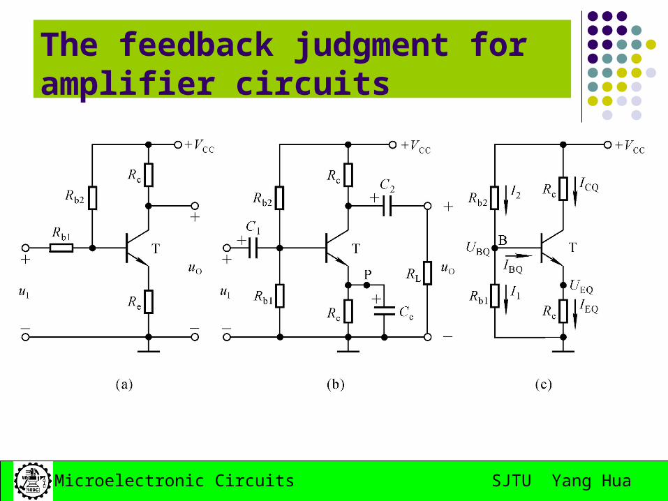
The feedback judgment for amplifier circuits
SJTU Yang HuaMicroelectronic Circuits
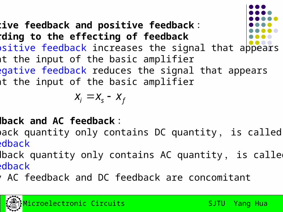
Negative feedback and positive feedback :According to the effecting of feedback1) positive feedback increases the signal that appears at the input of the basic amplifier2) negative feedback reduces the signal that appears at the input of the basic amplifier
DC feedback and AC feedback :1) Feedback quantity only contains DC quantity, is called DC feedback2) Feedback quantity only contains AC quantity, is called AC feedbackUsually AC feedback and DC feedback are concomitant
fsi xxx
SJTU Yang HuaMicroelectronic Circuits
The feedback judgment :
(a) No feedback(b) Feedback exists(c) No feedback
SJTU Yang HuaMicroelectronic Circuits
Instantaneous polarity method :
The judgment of feedback parity
1) Regulate the polarity of input signal relative to ground at sometime.
2) Decide all points’ parity step by step, at last get the parity of output signal.3) According to the parity of output signal decides the parity of amount of feedback.
4) If amount of feedback increases the signal that appears at the input of the basic amplifier, the circuit inducts the positive feedback. Otherwise, it inducts the negative feedback.
SJTU Yang HuaMicroelectronic Circuits
To integrated operational amplifiers , the input quantity can be UD or iN ( iP )
SJTU Yang HuaMicroelectronic Circuits
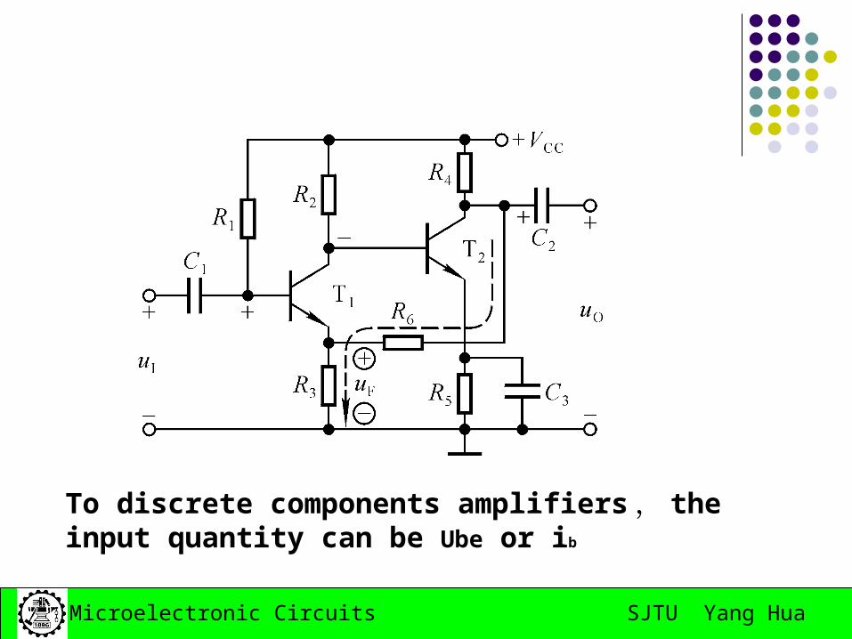
To discrete components amplifiers , the input quantity can be Ube or ib
SJTU Yang HuaMicroelectronic Circuits
AC feedback , no DC feedback
DC feedback , no AC feedback
The judgment of DC feedback and AC feedback
SJTU Yang HuaMicroelectronic Circuits
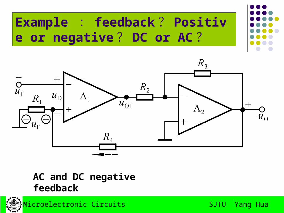
Example : feedback ? Positive or negative ? DC or AC ?
AC and DC negative feedback
SJTU Yang HuaMicroelectronic Circuits
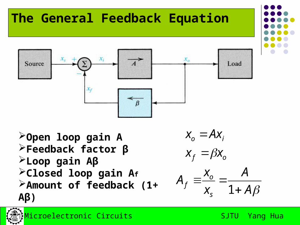
The General Feedback Equation
of
io
xx
Axx
AA
x
xA
s
of
1
Open loop gain A Feedback factor βLoop gain AβClosed loop gain Af
Amount of feedback (1+ Aβ)
SJTU Yang HuaMicroelectronic Circuits
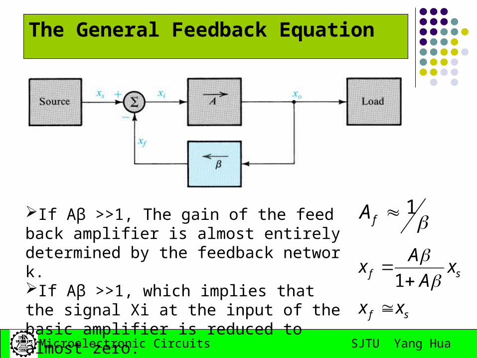
The General Feedback Equation
1fA
sf
sf
xx
xA
Ax
1
If Aβ >>1, The gain of the feedback amplifier is almost entirely determined by the feedback network. If Aβ >>1, which implies that the signal Xi at the input of the basic amplifier is reduced to almost zero.
SJTU Yang HuaMicroelectronic Circuits
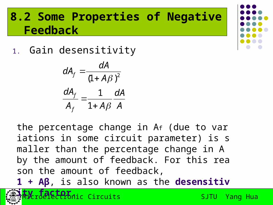
8.2 Some Properties of Negative Feedback
1. Gain desensitivity
A
dA
AA
dA
A
dAdA
f
f
f
1
1
)1( 2
the percentage change in Af (due to variations in some circuit parameter) is smaller than the percentage change in A by the amount of feedback. For this reason the amount of feedback, 1 + Aβ, is also known as the desensitivity factor.
SJTU Yang HuaMicroelectronic Circuits
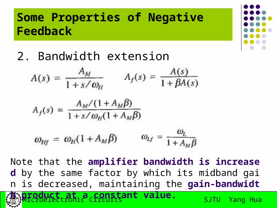
2. Bandwidth extension
Some Properties of Negative Feedback
Note that the amplifier bandwidth is increased by the same factor by which its midband gain is decreased, maintaining the gain-bandwidth product at a constant value.
SJTU Yang HuaMicroelectronic Circuits
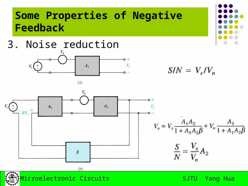
Some Properties of Negative Feedback
3. Noise reduction
SJTU Yang HuaMicroelectronic Circuits
Some Properties of Negative Feedback
4. Reduction in nonlinear distortion
D:\Ä£µç¿Î¼þ\¸º·´À¡.exe
SJTU Yang HuaMicroelectronic Circuits
Some Properties of Negative Feedback
4. Reduction in nonlinear distortion
SJTU Yang HuaMicroelectronic Circuits
Homework:
May 11th, 2008
8.1; 8.7;
SJTU Yang HuaMicroelectronic Circuits
PartII:The four basic feedback and analysis
SJTU Yang HuaMicroelectronic Circuits
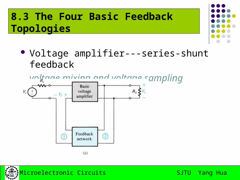
8.3 The Four Basic Feedback Topologies
Voltage amplifier---series-shunt feedback
voltage mixing and voltage sampling
SJTU Yang HuaMicroelectronic Circuits
The Four Basic Feedback Topologies
Current amplifier---shunt-series feedback
Current mixing and current sampling
SJTU Yang HuaMicroelectronic Circuits
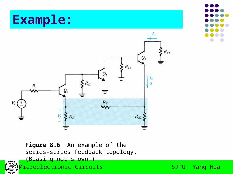
Example:
Figure 8.5 A transistor amplifier with shunt–series feedback. (Biasing not shown.)
Figure 8.6 An example of the series–series feedback topology. (Biasing not shown.)
SJTU Yang HuaMicroelectronic Circuits
Transresistance amplifier---shunt-shunt feedback
Current mixing and voltage sampling
The Four Basic Feedback Topologies
SJTU Yang HuaMicroelectronic Circuits
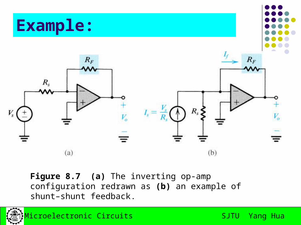
Example:
Figure 8.7 (a) The inverting op-amp configuration redrawn as (b) an example of shunt–shunt feedback.
SJTU Yang HuaMicroelectronic Circuits
Homework:
May 11nd, 2008
8.14; 8.15; 8.17; 8.19
SJTU Yang HuaMicroelectronic Circuits
8.4 The Series-Shunt Feedback Amplifier
The ideal situation The practical situation Summary
SJTU Yang HuaMicroelectronic Circuits
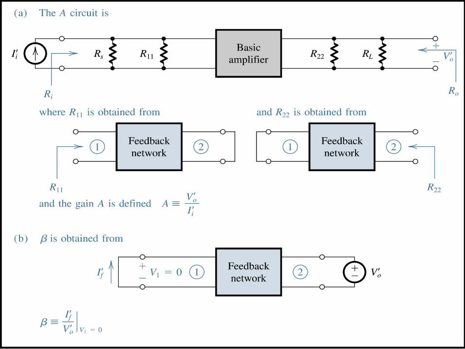
The Ideal Situation
A unilateral open-loop amplifier (A circuit).
An ideal voltage mixing voltage sampling feedback network (β circuit).
Assumption that the source and load resistance have been included inside the A circuit.
SJTU Yang HuaMicroelectronic Circuits
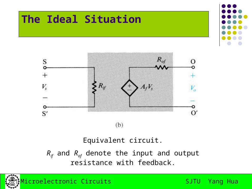
The Ideal Situation
Equivalent circuit.
Rif and Rof denote the input and output resistance with feedback.
SJTU Yang HuaMicroelectronic Circuits
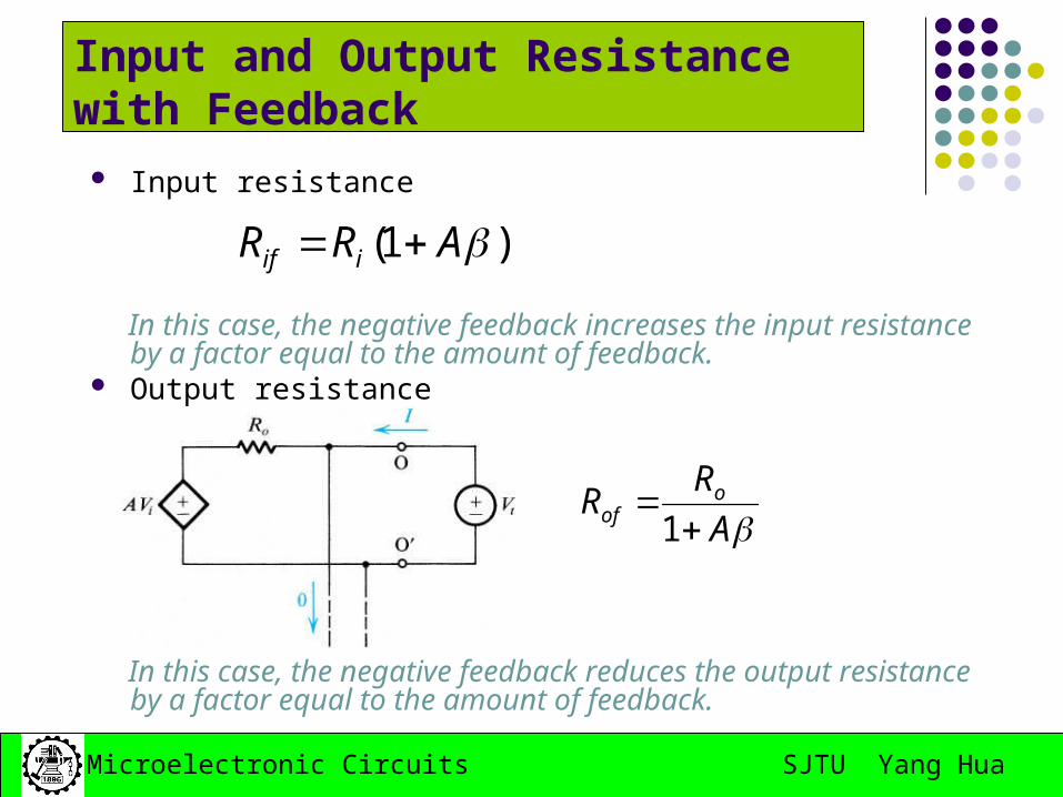
Input and Output Resistance with Feedback
Input resistance
In this case, the negative feedback increases the input
resistance by a factor equal to the amount of feedback. Output resistance
In this case, the negative feedback reduces the output
resistance by a factor equal to the amount of feedback.
)1( ARR iif
AR
R oof
1
SJTU Yang HuaMicroelectronic Circuits
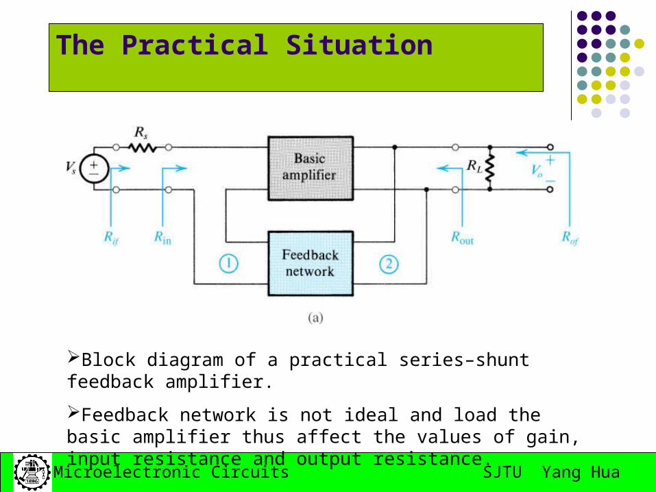
The Practical Situation
Block diagram of a practical series–shunt feedback amplifier.
Feedback network is not ideal and load the basic amplifier thus affect the values of gain, input resistance and output resistance.
SJTU Yang HuaMicroelectronic Circuits
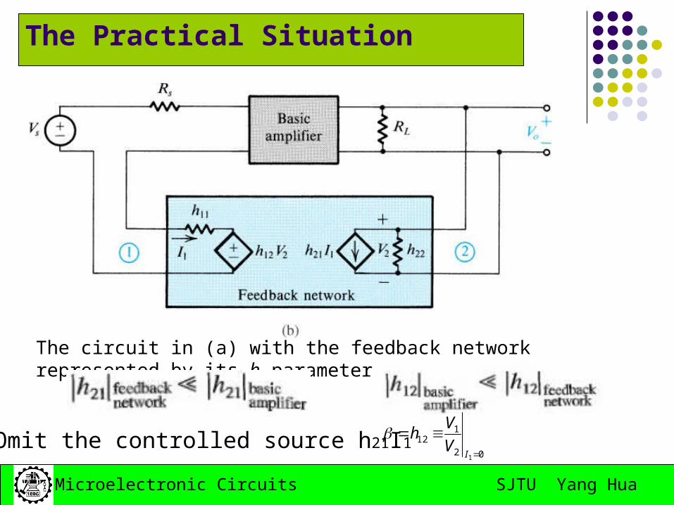
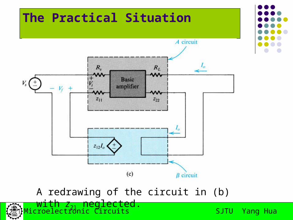
The Practical Situation
The circuit in (a) with the feedback network represented by its h parameters.
Omit the controlled source h21I102
112
1
I
V
Vh
SJTU Yang HuaMicroelectronic Circuits
The Practical Situation
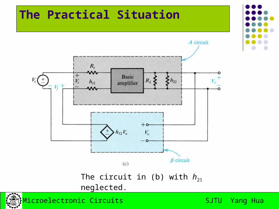
The circuit in (b) with h21 neglected.
SJTU Yang HuaMicroelectronic Circuits
The Practical Situation
The load effect of the feedback network on the basic amplifier is represented by the components h11 and h22.
The loading effect is found by looking into the appropriate port of the feedback network while the port is open-circuit or short-circuit so as to destroy the feedback.
If the connection is a shunt one, short-circuit the port. If the connection is a series one, open-circuit the port. Determine the β.
02
112
1
I
V
Vh
SJTU Yang HuaMicroelectronic Circuits
SJTU Yang HuaMicroelectronic Circuits
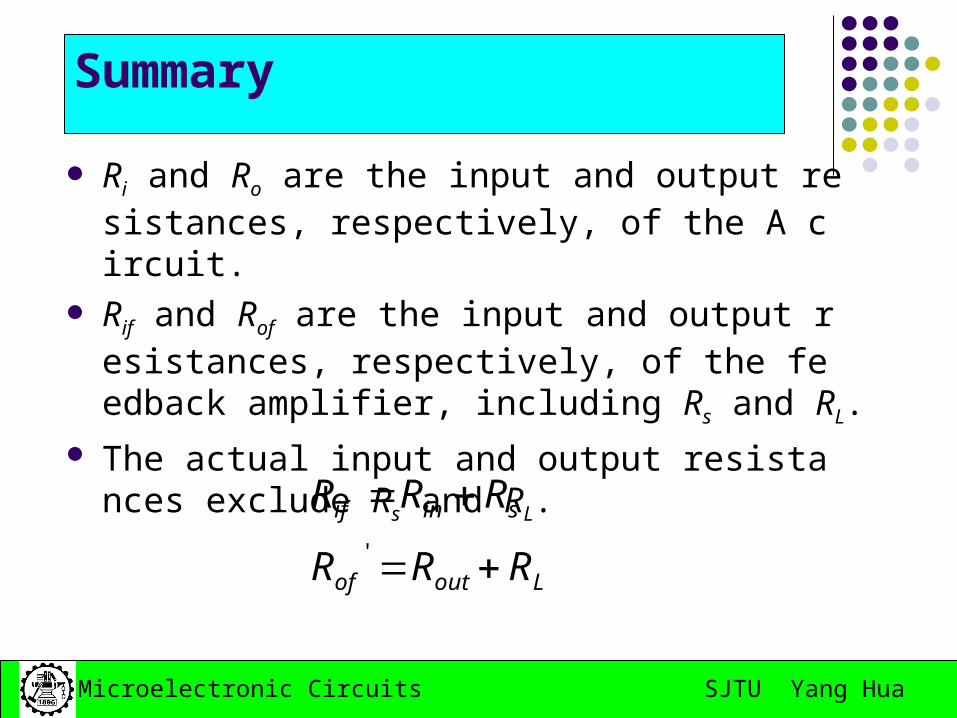
Summary
Ri and Ro are the input and output resistances, respectively, of the A circuit.
Rif and Rof are the input and output resistances, respectively, of the feedback amplifier, including Rs and RL.
The actual input and output resistances exclude Rs and RL.
Loutof
sinif
RRR
RRR
//
SJTU Yang HuaMicroelectronic Circuits
Example of Series-Shunt Feedback Amplifier
SJTU Yang HuaMicroelectronic Circuits
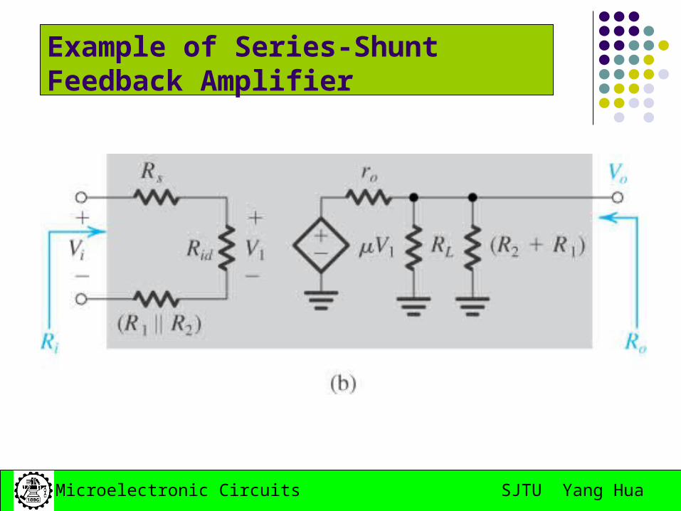
Example of Series-Shunt Feedback Amplifier
Op amplifier connected in noninverting configuration with the open-loop gain μ, Rid and ro
Find expression for A, β, the closed-loop gain Vo/Vi , the input resistance Rin and the output resistance Rout
Find numerical values
SJTU Yang HuaMicroelectronic Circuits
Example of Series-Shunt Feedback Amplifier
SJTU Yang HuaMicroelectronic Circuits
Example of Series-Shunt Feedback Amplifier
21
1
RR
R
V
V
s
f
SJTU Yang HuaMicroelectronic Circuits
8.5 The Series-Series Feedback Amplifier
The ideal situation The practical situation Summary
SJTU Yang HuaMicroelectronic Circuits
The Ideal Situation
Transconductance gain i
o
V
IA
SJTU Yang HuaMicroelectronic Circuits
The Ideal Situation
o
f
I
VTranresistance feedback factor
SJTU Yang HuaMicroelectronic Circuits
Input and Output Resistance with Feedback
Input resistance
In this case, the negative feedback increases the input resistance by a factor equal to the amount of feedback.
Output resistance
In this case, the negative feedback increases the output resistance
by a factor equal to the amount of feedback.
)1( ARR iif
)1( ARR oof
SJTU Yang HuaMicroelectronic Circuits
The Practical Situation
Block diagram of a practical series–series feedback amplifier.
Feedback network is not ideal and load the basic amplifier thus affect the values of gain, input resistance and output resistance.
SJTU Yang HuaMicroelectronic Circuits
The Practical Situation
The circuit of (a) with the feedback network represented by its z parameters.
SJTU Yang HuaMicroelectronic Circuits
The Practical Situation
A redrawing of the circuit in (b) with z21 neglected.
SJTU Yang HuaMicroelectronic Circuits
The Practical Situation
The load effect of the feedback network on the basic amplifier is represented by the components Z11 and Z22.
Z11 is the impedance looking into port 1 of the feedback network with port 2 open-circuited.
Z22 is the impedance looking into port 2 of the feedback network with port 1 open-circuited.
Determine the β.
02
112
1
I
I
Vz
SJTU Yang HuaMicroelectronic Circuits
SJTU Yang HuaMicroelectronic Circuits
Summary
Ri and Ro are the input and output resistances, respectively, of the A circuit.
Rif and Rof are the input and output resistances, respectively, of the feedback amplifier, including Rs and RL.
The actual input and output resistances exclude Rs and RL.
Loutof
sinif
RRR
RRR
'
SJTU Yang HuaMicroelectronic Circuits
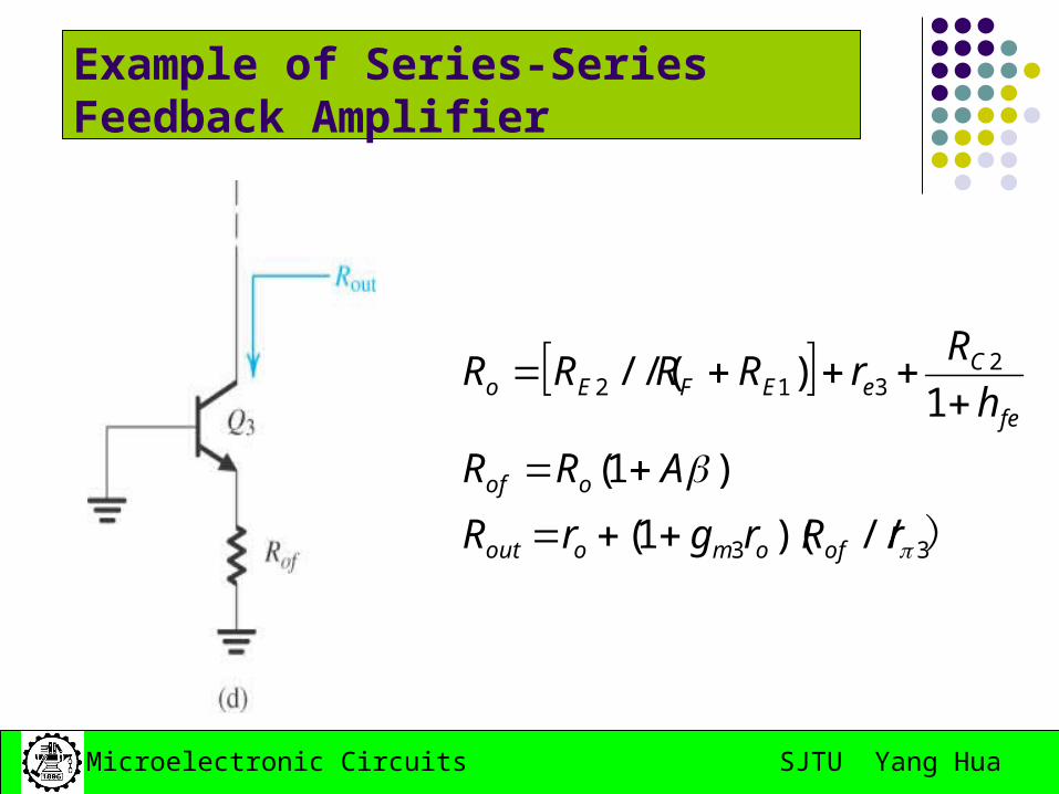
Example of Series-Series Feedback Amplifier
SJTU Yang HuaMicroelectronic Circuits
Example of Series-Series Feedback Amplifier
SJTU Yang HuaMicroelectronic Circuits
Example of Series-Series Feedback Amplifier
112
2E
EFE
E
o
f RRRR
R
I
V
SJTU Yang HuaMicroelectronic Circuits
Example of Series-Series Feedback Amplifier
)33
2312
//)(1(
)1(
1)//(
rRrgrR
ARR
h
RrRRRR
ofomoout
oof
fe
CeEFEo
SJTU Yang HuaMicroelectronic Circuits
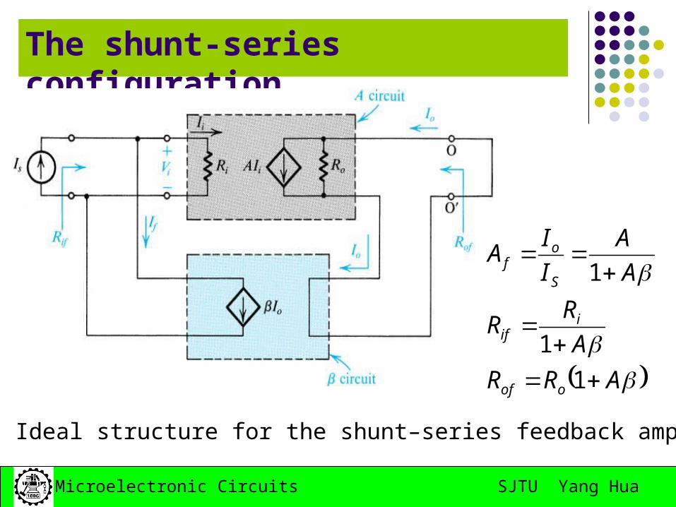
8.6 The Shunt-Shunt and Shunt-Series Feedback Amplifiers
Fig8.19. Ideal structure for the shunt-shunt feedback amplifier.
A
RR
A
RR
A
A
I
VA
oof
iif
S
of
1
1
1
SJTU Yang HuaMicroelectronic Circuits
The practical Shunt-Shunt feedback amplifier
SJTU Yang HuaMicroelectronic Circuits
SJTU Yang HuaMicroelectronic Circuits
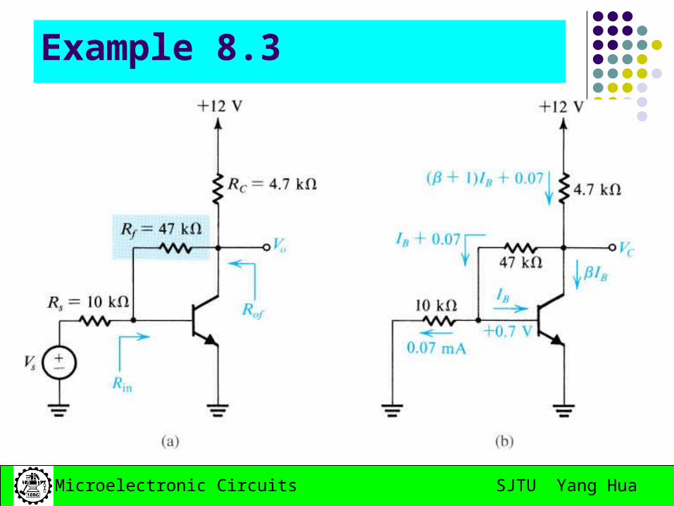
Example 8.3
SJTU Yang HuaMicroelectronic Circuits
SJTU Yang HuaMicroelectronic Circuits
The shunt-series configuration
Fig 8.22 Ideal structure for the shunt–series feedback amplifier.
ARR
A
RR
A
A
I
IA
oof
iif
S
of
1
1
1
SJTU Yang HuaMicroelectronic Circuits
A practical shunt-series feedback amplifier
SJTU Yang HuaMicroelectronic Circuits
SJTU Yang HuaMicroelectronic Circuits
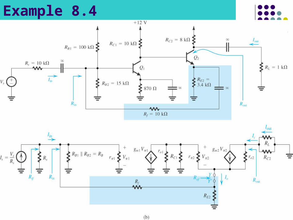
Example 8.4
SJTU Yang HuaMicroelectronic Circuits
SJTU Yang HuaMicroelectronic Circuits
summary
SJTU Yang HuaMicroelectronic Circuits
The method of finding A circuit
① h,z,r,g parameter method for two-port feedback network.
② Equivalent circuit method: Find the feedback network; Find the feedback network equivalent load Resistance to amplif
ier input, for output voltage sampling feedback, output short-circuit (Vo=0); for current sampling feedback, output Io open-circuit (Io=0).
Find the feedback network equivalent load Resistance to amplifier output, for input voltage mixing feedback, it should be disconnected from input to feedback network (Ii=0); for input current mixing feedback, let input connect to ground to disconnect from input signal to feedback network.
Any right-half-plane poles results in instability. Amplifier with a single-pole is unconditionally stable. Amplifier with two-pole is also unconditionally stable. Amplifier with more than two poles has the possibility
1) If ω180 is not exist, then the Amplifier is stable;2) If ω180 is exist and ω180< ω1, then the amplifier is not stable;3) If ω180 is exist and ω180> ω1, then the amplifier is stable;
SJTU Yang HuaMicroelectronic Circuits
The Definitions of the Gain and Phase margins
180lg20
AGm
Gain margin represents the amount by which the loop gain can be increased while stability is maintained.
Unstable and oscillatory
Stable and non-oscillatory
Only when the phase margin exceed 45º or gain margin exceed 6dB, can the amplifier be stable.
1
180
Am
SJTU Yang HuaMicroelectronic Circuits
Example:
SJTU Yang HuaMicroelectronic Circuits
Effect of phase margin on closed-loop response To see the relationship between phase margin and
Close-Loop gain, consider a feedback amplifier with a large low-frequency loop gain.
45 ,1
3.1
1
/1
1
180,1
1 ,1
1
1
11
1
mf
j
j
f
mj
fo
jA
e
e
jA
jAjA
ejA
AA
SJTU Yang HuaMicroelectronic Circuits
Stability analysis using Bode plot of |A|.
1log20log20log20 jAA
Hz6102.3
Hz5106.5
SJTU Yang HuaMicroelectronic Circuits
Stability Analysis Using Bode Plot of |A|
Gain margin and phase margin The horizontal line of inverse of feedback factor in dB. A rule of thumb:
The closed-loop amplifier will be stable if the 20log(1/β) line intersects the 20log|A| curve at a point on the –20dB/decade segment.
The general rule states:
At the intersection of 20log[1/ | β (jω)| ] and 20log |A(jω)| the difference of slopes should not exceed 20dB/decade.
SJTU Yang HuaMicroelectronic Circuits
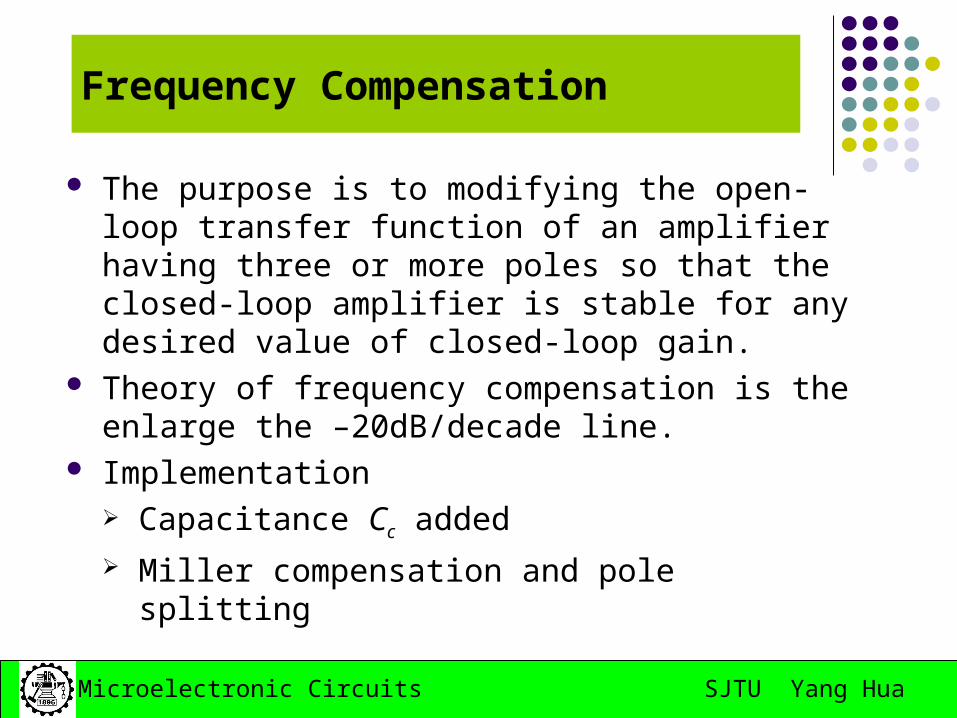
Frequency Compensation
The purpose is to modifying the open-loop transfer function of an amplifier having three or more poles so that the closed-loop amplifier is stable for any desired value of closed-loop gain.
Theory of frequency compensation is the enlarge the –20dB/decade line.
Implementation Capacitance Cc added Miller compensation and pole splitting
SJTU Yang HuaMicroelectronic Circuits
Frequency Compensation
xcxH
xxH
RCCf
RCf
)(2
1
2
1
'1
1
SJTU Yang HuaMicroelectronic Circuits
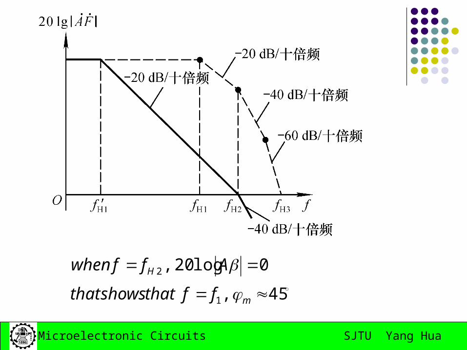
45 ,
0log20 ,
1
2
m
H
ffthatshowsthat
Affwhen
SJTU Yang HuaMicroelectronic Circuits
Frequency Compensation-Miller compensation
A gain stage in a multistage amplifier with a compensating capacitor connected in the feedback path