Microfluidic emulsification through a monolithic integrated glass micronozzle suspended inside a flow-focusing geometry Yifan Liu and Levent Yobas Citation: Applied Physics Letters 106, 174101 (2015); doi: 10.1063/1.4919444 View online: http://dx.doi.org/10.1063/1.4919444 View Table of Contents: http://scitation.aip.org/content/aip/journal/apl/106/17?ver=pdfcov Published by the AIP Publishing Articles you may be interested in Dynamics of step-emulsification: From a single to a collection of emulsion droplet generators Phys. Fluids 26, 082109 (2014); 10.1063/1.4892949 Corrugated interfaces in multiphase core-annular flow Phys. Fluids 22, 082002 (2010); 10.1063/1.3480561 Wetting gradient induced separation of emulsions: A combined experimental and lattice Boltzmann computer simulation study Phys. Fluids 20, 072104 (2008); 10.1063/1.2963958 Controlled production of emulsion drops using an electric field in a flow-focusing microfluidic device Appl. Phys. Lett. 91, 133106 (2007); 10.1063/1.2790785 Generation of monodisperse gel emulsions in a microfluidic device Appl. Phys. Lett. 88, 024106 (2006); 10.1063/1.2164393 This article is copyrighted as indicated in the article. Reuse of AIP content is subject to the terms at: http://scitation.aip.org/termsconditions. Downloaded to IP: 202.40.139.130 On: Mon, 29 Jun 2015 04:40:00
Transcript
Microfluidic emulsification through a monolithic integrated glass micronozzlesuspended inside a flow-focusing geometryYifan Liu and Levent Yobas Citation: Applied Physics Letters 106, 174101 (2015); doi: 10.1063/1.4919444 View online: http://dx.doi.org/10.1063/1.4919444 View Table of Contents: http://scitation.aip.org/content/aip/journal/apl/106/17?ver=pdfcov Published by the AIP Publishing Articles you may be interested in Dynamics of step-emulsification: From a single to a collection of emulsion droplet generators Phys. Fluids 26, 082109 (2014); 10.1063/1.4892949 Corrugated interfaces in multiphase core-annular flow Phys. Fluids 22, 082002 (2010); 10.1063/1.3480561 Wetting gradient induced separation of emulsions: A combined experimental and lattice Boltzmann computersimulation study Phys. Fluids 20, 072104 (2008); 10.1063/1.2963958 Controlled production of emulsion drops using an electric field in a flow-focusing microfluidic device Appl. Phys. Lett. 91, 133106 (2007); 10.1063/1.2790785 Generation of monodisperse gel emulsions in a microfluidic device Appl. Phys. Lett. 88, 024106 (2006); 10.1063/1.2164393
This article is copyrighted as indicated in the article. Reuse of AIP content is subject to the terms at: http://scitation.aip.org/termsconditions. Downloaded to IP:
This article is copyrighted as indicated in the article. Reuse of AIP content is subject to the terms at: http://scitation.aip.org/termsconditions. Downloaded to IP:
configuration, the droplets travel downstream following the
center stream without touching channel walls as a result of
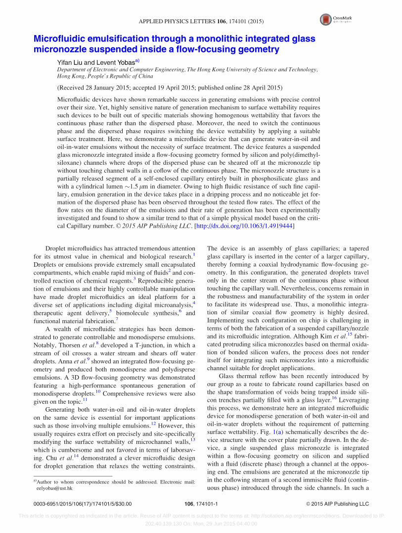
hydrodynamic focusing of the coaxial flow, Fig. 1(b), which
enables the generation of both water-in-oil and oil-in-water
emulsions being free of surface wettability. Thus, the device
employs a similar mechanism to that of the manually
assembled glass capillaries14 and yet introduces an integrated
approach that is more robust and mass producible.
The device fabrication involved the formation of a self-
enclosed round capillary and its subsequent release to define
the suspended micronozzle and flow-focusing channels, Fig.
1(c). Briefly, a layer of phosphosilicate glass (PSG), 5 lm
thick, was deposited through low-pressure chemical vapor
deposition (LPCVD) on silicon featuring a trench, 3 lm wide
and deep, created by deep reactive ion etch (DRIE). The
nonconformal step coverage profile of this layer left an elon-
gated void trapped within the trench, which was subse-
quently transformed into a cylindrical tube through glass
reflow under surface tension during a thermal anneal step
performed in N2 ambient (1000 �C for 1 h). The microfluidic
integration of the capillary into the flow-focusing geometry
as a suspended micronozzle was realized through standard
photolithography and subsequent dry etching steps; the PSG
layer was removed first by advanced oxide etch (AOE)
through the resist mask and then the exposed silicon was
etched by DRIE to a depth of 40 lm. Not only did these steps
form the channels but also they cut open both ends of the
capillary and outlined the capillary segment that would be
released into a suspended micronozzle. The subsequent
release step took place in SF6 plasma and left the channels
with an overall depth of 50 lm.
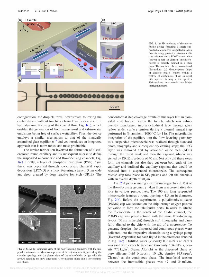
Fig. 2 depicts scanning electron micrographs (SEMs) of
the flow-focusing geometry taken from a representative de-
vice in various perspectives. The 100-lm long suspended
micronozzle features a round opening �1.5 lm in diameter,
Fig. 2(b). Before the experiments, a polydimethylsiloxane
(PDMS) cap was secured on the chip through oxygen plasma
activation to form the inlet/outlet ports. In order to situate
the micronozzle in the center of the fluidic channel, the
PDMS cap was pre-structured with the same flow-focusing
layout (50 lm in height) through soft lithography and care-
fully aligned to the chip with the aid of a microscope. To
generate droplets, the dispersed and continuous phases were
delivered into the respective channels using a syringe pump
(Harvard Apparatus) for each liquid in the directions denoted
in Fig. 2(c). Distilled water (viscosity 0.9 mPa s at 24 �C)
was used with either hexadecane (viscosity 3.34 mPa s, den-
sity 773 kg/m3, Sigma Aldrich) as the dispersed phase or
pure silicone fluid (viscosity 10 cSt, density 935 kg/m3,
Clearco) as the continuous phase. The interfacial tension
between the immiscible phases was 47 and 24 mN/m,
FIG. 1. (a) 3D rendering of the micro-
fluidic device featuring a single sus-
pended micronozzle integrated inside a
flow-focusing geometry between a sili-
con substrate and a PDMS cover plate
(shown in part for clarity). The micro-
nozzle is entirely defined in a PSG
layer. The insets are the cross-sectional
illustrations. (b) Monodisperse drops
of discrete phase (water) within a
coflow of continuous phase (mineral
oil) depicted forming at the tip of a
100-lm-long micronozzle. (c) Major
fabrication steps.
FIG. 2. SEM: (a) isometric view of the flow-focusing geometry with the sus-
pended micronozzle, (b) close-up view of the micronozzle tip revealing the
circular opening, and (c) planar view of the microfluidic design with the
arrows denoting the flow directions A for discrete phase and B for continu-
ous phase.
174101-2 Y. Liu and L. Yobas Appl. Phys. Lett. 106, 174101 (2015)
This article is copyrighted as indicated in the article. Reuse of AIP content is subject to the terms at: http://scitation.aip.org/termsconditions. Downloaded to IP:
202.40.139.130 On: Mon, 29 Jun 2015 04:40:00
respectively.17 No surfactant or plasma treatment was used.
We measured the rate of droplet formation f by counting the
generated droplets within a specified time interval, whereas
diameter of the droplets D was acquired by direct measure-
ments on the still images recorded. The images were cap-
tured under a microscope (Nikon) using a high-speed camera
(Phantom, Vision Research).
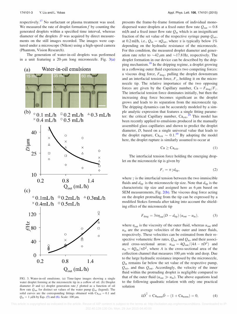
The generation of water-in-oil droplets was performed
in a unit featuring a 20-lm long micronozzle. Fig. 3(a)
presents the frame-by-frame formation of individual mono-
dispersed water droplets at a fixed outer flow rate Qout ¼ 0:8ml/h and a fixed inner flow rate Qin which is an insignificant
fraction of the set value of the respective syringe pump Qset,
at 0.2 ml/h, i.e., Qin ¼ aQset, where a is typically below 1%
depending on the hydraulic resistance of the micronozzle.
For this condition, the measured droplet diameter and gener-
ation rate refer to �42 lm and �17.8 Hz, respectively. The
droplet formation in our device can be described by the drip-
ping mechanism.18 In the dripping regime, a droplet growing
in a coflowing outer fluid experiences two competing forces:
a viscous drag force, Fdrag, pulling the droplet downstream
and an interfacial tension force, Fc, holding it on the micro-
nozzle tip. The relative importance of the two opposing
forces are given by the Capillary number, Ca ¼ Fdrag=Fc.
The interfacial tension force dominates initially, but then the
increasing drag force becomes significant as the droplet
grows and leads to its separation from the micronozzle tip.
The dripping dynamics can be accurately modeled by a sim-
ple analytic expression that features a single fitting parame-
ter: the critical Capillary number, Cacrit.19 This model has
been recently applied to emulsions produced in the manually
assembled glass capillaries and shown to predict the droplet
diameter, D, based on a single universal value that leads to
the droplet rupture, Cacrit � 0:1.19 By adopting the model
here, the droplet rupture is similarly assumed to occur at
Ca � Cacrit: (1)
The interfacial tension force holding the emerging drop-
let on the micronozzle tip is given by
Fc ¼ p cdtip; (2)
where c is the interfacial tension between the two immiscible
fluids and dtip is the micronozzle tip size. Note that dtip is the
characteristic tip size and assigned here as 6 lm based on
SEM measurements, Fig. 2(b). The viscous drag force acting
on the droplet protruding from the tip can be expressed by a
modified Stokes formula after taking into account the shield-
ing effect of the micronozzle tip
Fdrag ¼ 3pgoutðD� dtipÞ ðuout � uinÞ; (3)
where gout is the viscosity of the outer fluid, whereas uout and
uin are the average velocities of the outer and inner fluids,
respectively. These velocities can be estimated from their re-
spective volumetric flow rates, Qout and Qin, and their associ-
ated cross-sectional areas: uout ¼ 4Qout=ð4A� pD2Þ and
uin ¼ 4Qin=pD2, where A is the cross-sectional area of the
collection channel that measures 100 lm wide and deep. Due
to the large hydraulic resistance imposed by the micronozzle,
Qin remains far below the set value of the respective pump,
Qset, and thus Qout. Accordingly, the velocity of the inner
fluid within the protruding droplet is negligible compared to
that of the outer fluid (uout � uin). The above equations lead
to the following quadratic relation with only one practical
solution
kD̂2 þ CanormD̂ � ð1þ CanormÞ ¼ 0; (4)
FIG. 3. Water-in-oil emulsions. (a) Time-lapse images showing a single
water droplet forming at the micronozzle tip in a coflow of oil. (b) Droplet
diameter D and (c) droplet generation rate f plotted as a function of oil
flow rate Qout for distinct set values of the water pump Qset (legend). The
solid curves are the corresponding fittings obtained with Cacrit ¼ 0:1 and
Qin ¼ 1 ll/h by Eqs. (5) and (6). Scale: 100 lm.
174101-3 Y. Liu and L. Yobas Appl. Phys. Lett. 106, 174101 (2015)
This article is copyrighted as indicated in the article. Reuse of AIP content is subject to the terms at: http://scitation.aip.org/termsconditions. Downloaded to IP:
202.40.139.130 On: Mon, 29 Jun 2015 04:40:00
where k denotes the ratio of the cross-sectional area of the
micronozzle tip to that of the channel, d2tip=A, D̂ refers to the
diameter of the protruding droplet with respect to the size of
the micronozzle tip, D=dtip, and Canorm is defined here as the
ratio of Catip=Cacrit, with Catip representing the relative im-
portance of the viscous drag force at the micronozzle tip
against the interfacial tension force for a newly forming
droplet, i.e., Ftipdrag=Fc, where Ftip
drag � 3pgoutdtipQout=A.
Thus, Eq. (4) can be solved to obtain the scaled droplet
diameter
D̂ ¼ Canorm
2k�1þ
ffiffiffiffiffiffiffiffiffiffiffiffi1þ Dp� �
; (5)
where D ¼ 4kð1þ CanormÞ=Ca2norm.
Equation (5) predicts that, for a given inner/outer fluid
and micronozzle/channel dimensions, the diameter of the
detaching droplet decreases as Qout increases. Considering
the conservation of mass, the generation rate of droplets can
be stated as f � 6Qin=pD3 or alternatively in uin and D̂ as
f � 3
2
uin
dtip
D̂�1: (6)
In Figs. 3(b) and 3(c), the formation of water droplets
are compared at increasing oil flow rates for distinct set val-
ues of the water pump Qset (legend). The trends observed
here are in agreement with the predictions of the model
given by Eqs. (5) and (6). However, the model predictions
also suggest that the volumetric flow rate through the micro-
nozzle, Qin, remains limited to a small fraction of the pump
set value Qset (a below �1%). This is reasonable because
even for such a low flow rate, Qin� 1 ll/h, pressure drop
across the micronozzle amounts to nearly 3.25 bar which is
estimated based on the parabolic flow profile through the
tube diameter 0.75 lm and length 140 lm (inclusive of the
suspended 20-lm-long segment). Meanwhile, the majority
of the flow is compensated by the hydraulic capacitance of
the compliant tubing interface and PDMS cover. Although
the droplet diameter according to Eq. (5) is expected to
remain unchanged irrespective of Qin (thus Qset), one can
notice size variations across droplets obtained with distinct
levels of Qset, at a fixed Qout, Fig. 3(b). Such discrepancy is
not observed in the case of oil-in-water droplets generated in
a device featuring a 100-lm-long micronozzle, Fig. 4(b),
suggesting that the discrepancy might stem from the position
of the micronozzle tip within the flow-focusing geometry
where droplets break free. The oil droplets were sheared off
from the protruding micronozzle tip inside the collection
channel, Fig. 4(a), whereas the water droplets were pinched
off right at the junction without a fully developed coflowing
stream of the oil phase. This might have entailed forces and
flow types other than simple shear and hence introduced the
observed size dependence of droplets on the dispersed phase
flow.
Unlike the water-in-oil droplets, the oil-in-water drop-
lets were generated at higher continuous flow rates; at rela-
tively low water flow rates, the oil droplet interestingly
sticks on the glass micronozzle tip that ought to be hydro-
philic. This is probably due to the high surface roughness of
the sidewall glass left by dry etching, Fig. 2(b), or the
polymer film coatings deposited on the micronozzle surface
during etching. Fig. 4(a) presents time-lapse micrographs
showing the formation of an oil-in-water droplet at a fixed
responding to Qset ¼ 0:2 ml/h. The device used here features
a relatively long micronozzle extending 100-lm long. The
generation rate and droplet diameter were measured as
�7.0 Hz and �38 lm, respectively. Fig. 4(b) shows the
diameters of generated oil droplets plotted as a function of
water (outer) flow rates for distinct set values of the oil
pump, Qset (legend). As seen, the droplet diameter is fairly
FIG. 4. Oil-in-water emulsions. (a) Time-lapse images showing a single oil
droplet forming at the micronozzle tip in a coflow of water. (b) Droplet di-
ameter D and (c) droplet generation rate f plotted as a function of water flow
rate Qout for distinct set values of the oil pump Qset (legend). The solid
curves are the respective fittings obtained with Cacrit ¼ 0:1 and for distinct
values of Qin (legend) by Eqs. (5) and (6). Scale: 50 lm.
174101-4 Y. Liu and L. Yobas Appl. Phys. Lett. 106, 174101 (2015)
This article is copyrighted as indicated in the article. Reuse of AIP content is subject to the terms at: http://scitation.aip.org/termsconditions. Downloaded to IP:
202.40.139.130 On: Mon, 29 Jun 2015 04:40:00
independent of the oil flow rate, which is in accordance with
the model and unlike the case of the water-in-oil droplets
formed in the device with the relatively short micronozzle
(20 lm). The droplet diameter decreases inversely with the
continuous (water) flow rate, in strong agreement with Eq.
(5). Meanwhile, the generation rate increases drastically with
the increase of water flow rate, in agreement with Eq. (6)
based on the assumption of a� 0.1%, as presented in
Fig. 4(c).
It is worth noting that liquid jetting was not observed in
our device for both water-in-oil and oil-in-water emulsions.
In a previous work by Utada et al.,18 the dripping to jetting
transition was studied in coflowing liquid streams based on a
coaxial capillary assembly and found to occur in two distinct
classes. The first class of transition is driven by the flow rate
of the outer continuous phase and occurs spontaneously
when the capillary number of the outer continuous phase
becomes increasingly large, i.e., Caout � Oð1Þ. This capillary
number, Caout ¼ goutuout=c, corresponds to Catip in our
model and hardly exceeded 0.05 here. The second class of
transition to jetting is driven by an excessive increase of the
inner flow rate which occurs when the Weber number of the
inner dispersed phase, Win ¼ qindtipu2in=c with qin is the dis-
persed phase density, gets equally large, i.e., Win � Oð1Þ.Yet, in our experiments, the inertia of the dispersed phase
was extremely small and hence Win � 1. While it is reason-
able to expect the transition to jetting in our device with an
increased outer flow rate to the extent that Caout � Oð1Þ, it
would be rather difficult to reach jetting through an increased
inner flow rate, Win � Oð1Þ, due to the difficulty with setting
an extremely large pressure drop across the micronozzle.
In conclusion, we have demonstrated a facile method
of generating emulsions independent of the surface wettabil-
ity using a monolithic device featuring a suspended glass
micronozzle integrated into a microfluidic flow-focusing
geometry. This device offers interesting possibilities for a set
of applications such as multiple emulsions.
This research was supported by a grant from the
Research Grant Council of Hong Kong (No. GRF621513).
1S. Y. Teh, R. Lin, L. H. Hung, and A. P. Lee, Lab Chip 8, 198 (2008).2J. D. Tice, H. Song, A. D. Lyon, and R. F. Ismagilov, Langmuir 19, 9127
(2003).3H. Song, D. L. Chen, and R. F. Ismagilov, Angew. Chem. Int. Ed. 45,
7336 (2006).4V. Srinivasan, V. K. Pamula, and R. B. Fair, Lab Chip 4, 310 (2004).5M. J. Lawrence and G. D. Rees, Adv. Drug Delivery Rev. 45, 89 (2000).6L. Mazutis, A. F. Araghi, O. J. Miller, J. C. Baret, L. Frenz, A. Janoshazi,
V. Taly, B. J. Miller, J. B. Hutchison, D. Link, A. D. Griffiths, and M.
Ryckelynck, Anal. Chem. 81, 4813 (2009).7I. Shestopalov, J. D. Tice, and R. F. Ismagilov, Lab Chip 4, 316 (2004).8T. Thorsen, R. W. Roberts, F. H. Arnold, and S. R. Quake, Phys. Rev.
Lett. 86, 4163 (2001).9S. L. Anna, N. Bontoux, and H. A. Stone, Appl. Phys. Lett. 82, 364
(2003).10L. Yobas, S. Martens, W. L. Ong, and N. Ranganathan, Lab Chip 6, 1073
(2006).11R. Seemann, M. Brinkmann, T. Pfohl, and S. Herminghaus, Rep. Prog.
Phys. 75, 016601 (2012); C. N. Baroud, F. Gallaire, and R. Dangla, Lab
Chip 10, 2032 (2010); P. S. Dittrich and A. Manz, Nat. Rev. Drug
Discovery 5, 210 (2006).12S. Okushima, T. Nisisako, T. Torii, and T. Higuchi, Langmuir 20, 9905
(2004).13A. R. Abate, J. Thiele, M. Weinhart, and D. A. Weitz, Lab Chip 10, 1774
(2010).14L. Y. Chu, A. S. Utada, R. K. Shah, J. W. Kim, and D. A. Weitz, Angew.
Chem. Int. Ed. 46, 8970 (2007).15W. Kim, M. Q. Guo, P. D. Yang, and D. J. Wang, Anal. Chem. 79, 3703
(2007).16Y. F. Liu and L. Yobas, Biomicrofluidics 6, 046502 (2012).17S. van der Graaf, C. G. P. H. Schroen, R. G. M. van der Sman, and R. M.
Boom, J. Colloid Interface Sci. 277, 456 (2004).18A. S. Utada, A. Fernandez-Nieves, H. A. Stone, and D. A. Weitz, Phys.
Rev. Lett. 99, 094502 (2007).19R. M. Erb, D. Obrist, P. W. Chen, J. Studer, and A. R. Studart, Soft Matter
7, 8757 (2011).
174101-5 Y. Liu and L. Yobas Appl. Phys. Lett. 106, 174101 (2015)
This article is copyrighted as indicated in the article. Reuse of AIP content is subject to the terms at: http://scitation.aip.org/termsconditions. Downloaded to IP: