46
Microscopy Lectures on Medical Biophysics Dept. Biophysics, Medical faculty, Masaryk University in Brno
| Date post: | 26-Dec-2014 |
| Category: |
Technology |
| Upload: | mubosscz |
| View: | 926 times |
| Download: | 0 times |

Microscopy
Lectures on Medical Biophysics
Dept. Biophysics, Medical faculty, Masaryk University in Brno

Lecture outline
• Compound microscope and its variants– Physical principles of microscopy– Phase contrast– Fluorescence microscope
• Optical scanning microscopes– Confocal scanning microscope– Near field optical scanning microscope
• Electron microscopy– Transmission electron microscopy– Scanning electron microscopy– Scanning tunnelling microscope
• Microscopes based on other physical principles– Atomic force microscopy– Acoustic microscopy

Prerequisites
• What should you know?Fundamentals
of geometric and wave optics.

Compound microscope and its variants
Physical principles of microscopy• The spatial resolution (SR) of the unaided eye at a distance of 25 cm
is about 14 lines per mm. • The magnifying glass can increase this substantially (for high SR we
require large diameter of lens and smaller focal length) However, it does not have a high enough SR to allow us to study the microstructure of living matter.
• The first microscope was manufactured in The Netherlands in the end of 16th century. Anthony van Leuwenhoek (1632-1723) improved its construction after 1650 (could see say 2000 lines per mm).
• The construction of the electron microscope (in 30th of 20th century) was the next milestone of microscopy. The SR of microscopes improved about 1000-times more than the optical microscope, so it was possible to see big molecules. Today we can resolve even individual atoms.
• In principle, we can use any wave motion to depict microscopic objects. The only condition is that the wavelength must be shorter than the dimensions of the observed object.

The first usable microscope(17th century)
www.arsmachina.com/images/ loeuwenhoek_thmb.jpg.

Scheme of the microscope and properties of its optical system
• Basic parts: two systems of lenses - objective and eyepiece. (Both approx. converging lenses).
• Considering the quality of the image, the most important part is the objective which forms a real, magnified and inverted image. The observed object must be placed between F (position of the focus) and 2F. The objective can be considered as a convex lens of very short focal length for high SR.
• The mechanical piece connecting the objective with the eyepiece is called the drawtube. The image formed by the objective (positioned just behind the front focus of the eyepiece) is observed by the eyepiece in the manner of a simple magnifying glass. A magnified, inverted and virtual image results.
• The condenser optical system focuses light onto the observed object, and ensures its perfect illumination.

Optical scheme and magnification of the microscope
F – focal points, f – focal distances, y - object, y' – real image of the object formed by the objective, y'' – virtual image seen in the eyepiece, – optical interval of the microscope.
eyepiece
objective
d - distance of the most distinct vision (0,25 m), - optical interval of the microscope, fob a fep are the respective focal distances.

Microscope Objectives
http://www.microscopyu.com/articles/optics/objectivespecs.html

Objective Specifications• Numerical Aperture (NA, max. value approx. 1.5) - This is the most important
specification: it determines the light acceptance angle (which determines the brightness of the image, the higher the NA the higher the acceptance angle), the limiting SR (prop. to NA), and the depth of field (inversely prop. to NA2).
• Linear Magnification • Optical Corrections - Achro and Achromat (achromatic), Fl, Fluar, Fluor,
Neofluar, Fluotar (fluorite, better spherical and chromatic corrections), Apo (apochromatic, highest correction for spherical and chromatic aberrations)
• Cover Glass Thickness (standard thickness 0.17 mm). Some objectives have a correction collar to compensate for any variation from this standard.
• Working Distance - Distance between objective front lens and top of cover glass when the specimen is in focus. Decreases as magnification increases. Newer objectives have the working distance in mm inscribed on the barrel.
• Immersion Medium - Most objectives are designed to image specimens with air as the medium between the objective and the cover glass. To attain higher NA, many objectives are designed to image the specimen through another medium that reduces refractive index differences between glass and the imaging medium. High-resolution planapochromatic objectives can achieve numerical apertures up to 1.40 when the immersion medium is special oil with a refractive index of 1.51. Other media are water and glycerin.
• Color Codes - Microscope manufacturers label their objectives with color codes to help in rapid identification of the magnification and immersion media requirements.
http://www.microscopyu.com/articles/optics/objectivespecs.html

Use of Immersion Media
Immersion media are used to increase the NA.
The left ray leaving the slide is refracted on the interface between the cover glass and air away from the normal and cannot take part in the image formation. The right ray passing from glass into the immersion medium (which has a refractive index close to that of glass) does not change its direction and contributes to the image.

SR limit of the microscope• The SR limit is proportional to the NA and inversely proportional to the
wavelength of light used (German physicist Abbe,1840-1905).• In some textbooks of microscopy, the SR is calculated by the formula:
= /NA where is distance of two still distinguishable points (NA = n.sin, n is
refraction index of medium between the objective and the cover glass and is the above mentioned acceptance angle).
• SR increases with magnification. By combining strong converging lenses, we could construct a microscope with almost arbitrary magnification, however we find that beyond a certain limit (limit of ‘useful magnification’) there is no further increase in the limiting SR (just ‘empty’ magnification’).
• SR decreases if the condenser aperture is reduced however the contrast resolution (CR) increases! Hence for a given specimen one must choose a condenser aperture to provide a balance between SR and CR. If one just needs to reduce brightness it is best to turn down the voltage to the lamp then decrease the condenser aperture so that one does not reduce the SR.

Depth of Field Z
• This is the thickness of objects along the z-axis which is simultaneously in focus. Important for thicker specimens.
2NA
nZ
n is refractive index of the specimen (liquid surrounding the microscopic object)
Special optical microscopes
• Observation in bright or dark field • Stereomicroscope (two microscopes with individual objectives
and eyepieces with optical axes at an angle of about 15°) - stereoscopic vision. In medicine: microsurgery. The image must not be inverted. The surgery field is illuminated by optical fibres. The possibility of changes in the focal length of the objective produces zooming – a variable spatial resolution.
• Modern research microscopes ere equipped with digital cameras for microphotography or microcinematography (video recording).
• Image processing software: performs changes of contrast, brightness, sharpness etc. Advanced software enables quantitative analysis of images, searching for typical patterns etc.
• Most kinds of microscopes can be set up by changing the objectives, eyepieces, condensers, or by addition of some special optical elements. Many accessories are available, e.g. micromanipulators used to place microelectrodes into cells, separate organelles etc.

Stereomicroscope
•The OPMI® Vario/NC 33 surgical microscope

Phase Contrast Microscopes
A technique that produces contrast images of biological specimens, which structures have similar light attenuation (all equally transparent and therefore produce little contrast in normal transmission microscopy) but have slight differences in refractive index (and hence produce differential phase). The phase contrast technique changes the phase differences into amplitude differences. Living cells can be examined without being fixed, and stained. Principle: The annular diaphragm is added in condenser frontal focus plane - light passes through a narrow, ring-shaped slot. As the light passes through the object, the rays are deflected from the original direction. In the objective back focal plane is a phase plate, shaped like the annulus again, which shifts the phase by +/2 or -/2), i.e. by 1/4 of the wavelength. This plate transmits rays which did not change their direction on phase objects. Other rays miss the plate, their phase is not shifted. The picture is formed by interference of the phase-shifted and non-shifted rays. The phase objects seem dark or bright in comparison with their surrounding (positive or negative contrast).
According to http://www.nobel.se/physics/educational/microscopes/phase/

Phase contrast microscope
Amoeba seen in phase contrast – M = 250x (www.durr.demon.co.uk/ colour.html.)
Many colourless biological objects (difficult to observe in a common microscope) are phase objects. Dyes and stains can make them visible, but they often poison the cells. Phase contrast microscopes allow to observe such objects without staining.

Fluorescence microscope•Fluorescence microscopy is based on the ability of some substances to emit visible light after irradiation by light of shorter wavelength (UV radiation or violet light). •The optics of the condenser must be adapted to UV light, which can be also supplied through the objective (upper illumination). The remaining part of the microscope is identical with the same part of a common microscope. Eye protecting UV filters are needed. •The fluorescence is exhibited e.g. by tryptophan or other compounds with an aromatic ring or heterocycle. In most cases, fluorescent dyes specifically interacting with various cell structures are added to the observed biological objects. Sometimes the dye (fluorochrome, fluorescence probe) is bound to an antibody specific for some protein. This immunofluorescence method can selectively visualise e.g. the cytoskeleton, chromatin, membrane proteins.

Fluorescence microscope
Actin fibres of yeasts visualised by fluorescence microscopy – stained by rhodamin-phalloidin
•www.paulgyoung.com/.../ fission_yeast_actin_cytoskeleton.htm.
Virions in an infected cell - http://usa.hamamatsu.com/sys-biomedical/slcn2400/slcn-smpl.htm
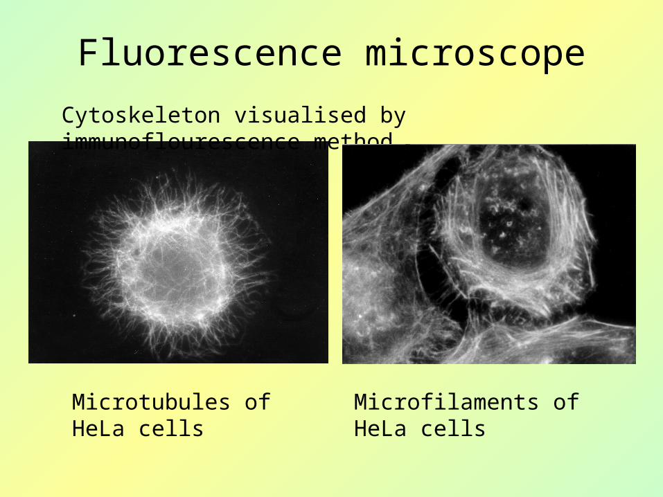
Cytoskeleton visualised by immunoflourescence method
Microtubules of HeLa cells
Microfilaments of HeLa cells
Fluorescence microscope

Confocal laser scanning microscope
•L - laser, C – diaphragms with small circular opening, PPZ – semitransparent mirror, DET – light detector (photomultiplier), SM – scanning mechanism, Č - objective (projective), O – point object, PREP – microscopic section. •Only rays reflected from point structures in the focus can pass through the diaphragm C in front of the detector. Other rays (scattered) are stopped by the diaphragm. These rays would lower the image quality in a common microscope since they lower the contrast. Using this microscope, we can study relatively thick native sections. The scanning mechanism is a system of rotating mirrors which can move the focus along dense parallel lines.

Confocal scanning microscope
3D image of a neuron, fluorescence - http://www.cs.ubc.ca/nest/magic/neuron.html
Immunofluorescence method is often used for specification of observed structures – to mark chromosomes, membrane receptors etc.

Confocal microscope
• Live Cell Imaging- we can follow the growth of cell cultures in a flow-through cell in real time
• We can follow direct effects of chemical of physical factors on cell cultures.
• Development: + simultaneous use of a built-in spectrophotometer,
common laser replaced by a „white laser“, i.e. laser tunable continuously in wavelength range of 470-670 nm (Leica).
+ Raman spectrometer- contactless, non-destructive chemical analysis of materials; (see the lecture on devices used in molecular biophysics)

Optical scanning microscopes
Near field optical scanning microscope
NFOSM = NSOM = SNOMScheme of the near field optical scanning microscope. A narrow beam of argon laser light passes through a very narrow opening (5 – 10 nm in diameter) in a metal-coated glass tip. A thin section moves above the opening at a constant distance. According Rontó and Tarján (1994).

Light transmitting tip of NFOSM seen in common optical microscopehttp://physics.nist.gov/Divisions/Div844/facilities/nsom/nsom.html
Plasmid DNA – 10 000 nucleotides
•http://www.snom.omicron.de/examples/twinsnom/x-tsnom_12.html
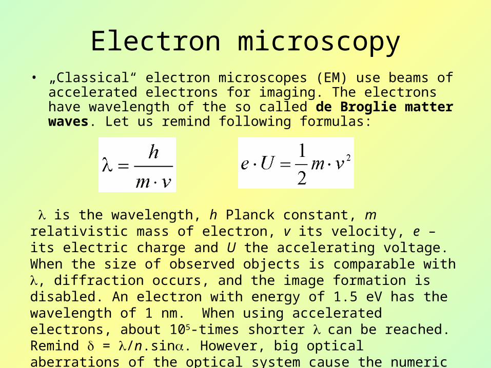
Electron microscopy• „Classical“ electron microscopes (EM) use beams of accelerated
electrons for imaging. The electrons have wavelength of the so called de Broglie matter waves. Let us remind following formulas:
is the wavelength, h Planck constant, m relativistic mass of electron, v its velocity, e – its electric charge and U the accelerating voltage. When the size of observed objects is comparable with , diffraction occurs, and the image formation is disabled. An electron with energy of 1.5 eV has the wavelength of 1 nm. When using accelerated electrons, about 105-times shorter can be reached. Remind = /n.sin. However, big optical aberrations of the optical system cause the numeric aperture is very small - in the order of 10-2. EM resolving power is several tenth of nm in practice.

Electron microscopy
Magnetic lens
Transversal section of a coil which is magnetically shielded by cladding. The electron beam is focused in the place where is a gap in the cladding. The magnetic lens acts as a converging lens for electrons.
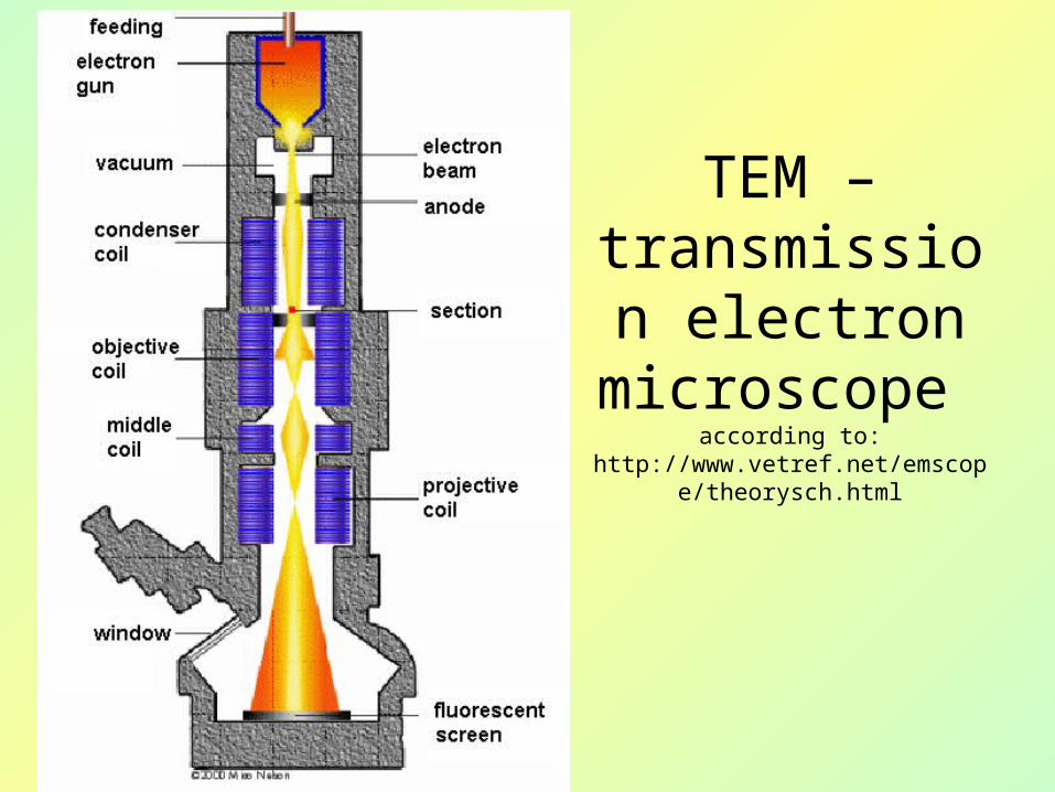
TEM – transmission
electron microscope
according to:http://www.vetref.net/emscope/theorys
ch.html
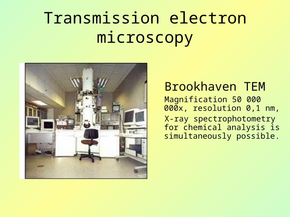
Transmission electron microscopy
Brookhaven TEM Magnification 50 000 000x, resolution 0,1 nm, X-ray spectrophotometry for chemical analysis is simultaneously possible.
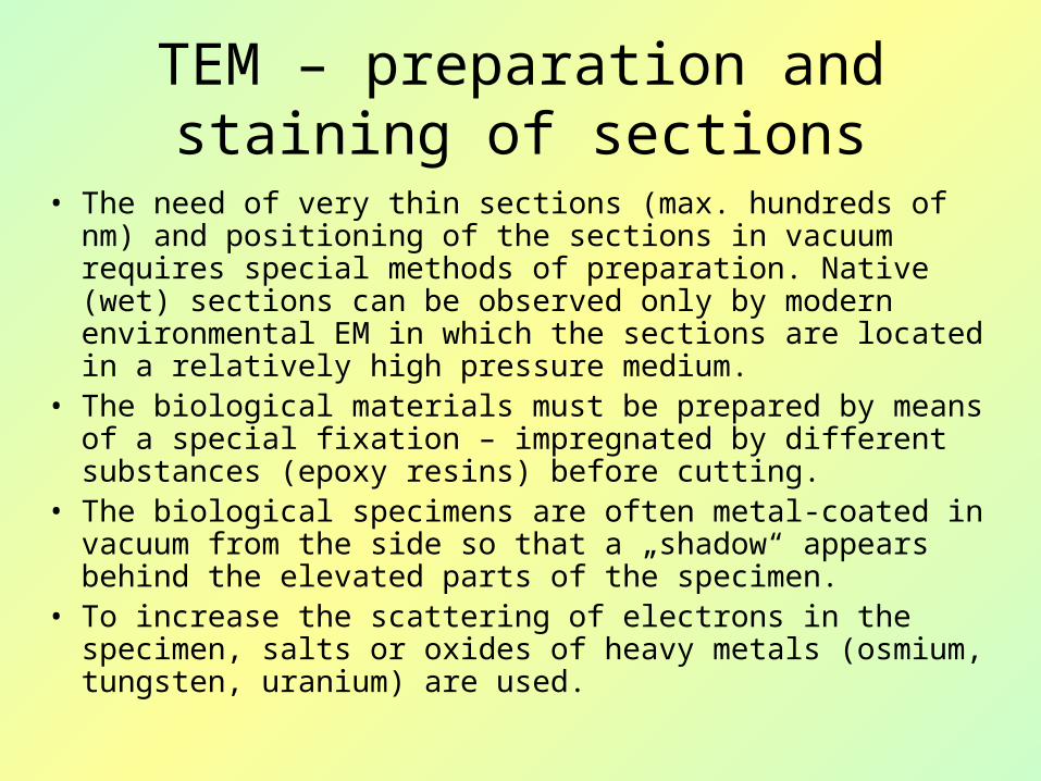
TEM – preparation and staining of sections
• The need of very thin sections (max. hundreds of nm) and positioning of the sections in vacuum requires special methods of preparation. Native (wet) sections can be observed only by modern environmental EM in which the sections are located in a relatively high pressure medium.
• The biological materials must be prepared by means of a special fixation – impregnated by different substances (epoxy resins) before cutting.
• The biological specimens are often metal-coated in vacuum from the side so that a „shadow“ appears behind the elevated parts of the specimen.
• To increase the scattering of electrons in the specimen, salts or oxides of heavy metals (osmium, tungsten, uranium) are used.

TEM – preparation and staining of sections
• Kryofixation = an attempt to replace slow chemical fixation by faster fixation by freezing
• Rapid freezing of a native sample under high pressure (MPa) and temperature of liquid nitrogen (-190 °C)
• Disadvantage: the samples have to be manipulated using cooled instruments (from –190°C to – 4°C), TEM is cooled by liquid nitrogen.
• Freeze-etching method: metallic replicas of surfaces of cellular membrane structures are prepared
• The sample is fractured in high vacuum (10-5 Pa) at temperature of –100°C. The exposed structures are coated by a thin layer of a heavy metal (Pt, Ta) under the angle of (45°), so that a „shadow“ appears behind the elevated parts of the specimen. Then a layer of carbon is added under an angle of 90°, which is necessary for fixation of the metallic structures
• Total layer thickness is about 25 nm• Biological material is then removed chemically

TEM- section vs. replica
HL-60 cells, fragment of nucleus, morphological changes during apoptosis. Left picture – ultrathin section, OsO4 contrast. Right picture - replica, coating by a layer of Pt and C.Obtained using TEM MORGAGNI 268 D (Philips), recorded by a CCD camera.

TEM working at low accelarating voltage LV-STEM vs. LV-TEM
• Relatively thick ultrathin sections: 30-40 nm for biological material
• No need to use heavy metal contrast• Spatial resolution in LV-STEM 1-2 nm
LV-STEM micrograph, crystals of polypropylene, frame width 9,7m, accelerating voltage of 25 kV.
LV-TEM micrograph, crystals of polypropylene, frame width 6,3 m, accelerating voltage 5 kV.
Lednický at all., Polymer 41, 2000.
LV-EM developed by Delong Instruments, Brno

TEM -http://www.ualberta.ca/~mingc
hen/tem.htm
Cells of abdominal muscle
Corona virus, negative staining

Electron microscopy
Scanning electron microscopy

SEM
According: http://www.rpi.edu/dept/materials/COURSES/NANO/shaw/BigSEM.gif

SEM – preparation of specimens
• Biological specimens have to be dried at low temperature in CO2 atmosphere
• Non-conducting materials have to be coated by thin metal layer (Au, C, Ag – vaporised metals are applied)
• The microscopes with low accelerating voltage - advantages: less artefacts, smaller damage of specimens, smaller or no metal layer (MIRA produced by TESCAN)
• Possibility to study chemical composition of the specimen by X-ray spectrometry (structures bigger than 200 nm)
• Development of microscopes enabling simultaneous observation of the surface and cutting

SEM – MIRA, crystals prepared for X-ray analysis

• Ant leg detail in SEM - http://www.wtn.org/ss/story.phtml?storyId=33&type=EdOutreach
•Sea urchin egg surrounded by
spermatozoa, SEM 3000x magnified -
http://www.stanford.edu/dept/news/report/news/august9/sperm-89.html

Electron microscopy
Scanning tunnelling microscope (STM)
Scheme of the Scanning tunnelling electron microscope (STM). Detail of the metallic detecting needle can be seen below. The positively charged needle copies the sample surface. According to Rontó and Tarján (1994).
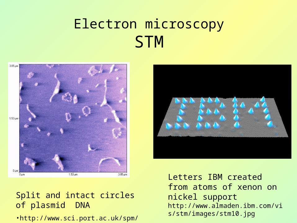
Letters IBM created from atoms of xenon on nickel support http://www.almaden.ibm.com/vis/stm/images/stm10.jpg
Split and intact circles of plasmid DNA
•http://www.sci.port.ac.uk/spm/overfig5.htm
Electron microscopy
STM

Microscopes based on other physical principles
Atomic force microscopy
•AFM – Atomic force microscopy – a fine metallic tip follows the surface profile
•http://physchem.ox.ac.uk/~rgc/research/afm/afm1.htm

AFM
AFM – Atomic force microscopy
Plasmid DNA – 10 000 nucleotides,•http://www.snom.omicron.de/examples/twinsnom/x-tsnom_12.html
Crystalline structure of silicon – atomic resolution •http://www.omicron-instruments.com/ products/afm_stm/r_afmst6.html

DNA image from AFM - http://spm.phy.bris.ac.uk/research/DNA/image
s/dna2.jpg

Microscopes based on other physical principles
Acoustic microscopy
• Neurons growing on a plastic plate http://transducers.stanford.edu/stl/Projects/ControlledPatt.htm
•According to: http://www.sv.vt.edu/comp_sim/sam/full.gif
Authors: Vojtěch Mornstein, Naděžda Vaškovicová
Content collaboration and language revision: Carmel J. Caruana
Presentation design: -
Last revision: September 2009


