MicroVision Plus (mMOTOR) Technical Manual P&B Engineering (UK) Ltd Belle Vue Works Boundary Street Manchester M12 5NG +44 (0)161 230 6363 +44 (0)161 230 6464 www.pbeng.co.uk [email protected]t f w e
Transcript
MicroVision Plus (µMOTOR)
Technical Manual
P&B Engineering (UK) Ltd Belle Vue Works Boundary Street
Manchester M12 5NG
+44 (0)161 230 6363 +44 (0)161 230 6464 www.pbeng.co.uk [email protected] t f w e
µMOTOR TECHNICAL MANUAL
Issue 6 25/04/2005
Contents
1. P&B MICROVISIONPLUS, Motor Variant (µMOTOR)........................................................................ 1
4.1. POWER SUPPLY LIVE. ........................................................................................................................................... 6 4.2. VOLTAGE REFERENCE. .......................................................................................................................................... 6 4.3. CURRENT SENSOR INPUTS. ................................................................................................................................... 6
4.3.1. Hall Effect Sensors................................................................................................................................... 6 4.3.2. Conventional Current Transformers. ..................................................................................................... 7
4.4. TEMPERATURE INPUT. .......................................................................................................................................... 7 5. Microvision+ Control Outputs. ............................................................................................................. 7
9.3.1. Motor Control. ........................................................................................................................................ 17 9.3.2. Motor Settings. .................................................................................................................................................... 17 9.3.3. Serial Settings. ..................................................................................................................................................... 17
9.3.5. Current Options...................................................................................................................................... 20 9.3.6. Voltage Options. .................................................................................................................................................. 20
9.3.7. Motor Options. ....................................................................................................................................... 21 9.3.8. External Fault Options........................................................................................................................... 21 9.3.9. Temperature Options. ........................................................................................................................... 22 9.3.10. System Settings. .................................................................................................................................. 22 9.3.11. I / O Settings. ...................................................................................................................................... 22
10. Menu Tree Structure. ......................................................................................................................... 24 11. MicroVision Plus Settings Summary. .............................................................................................. 25 11.1. MicroVision Plus Control Setting Summary. .............................................................................. 26 11.2. MicroVision Plus Protection Setting Summary.......................................................................... 27 12. Serial Settings..................................................................................................................................... 28 12.1. PROFIBUS DP (Optional)............................................................................................................... 29 13. Motor Settings. ................................................................................................................................... 32 14. Starting Methods. ............................................................................................................................... 34
14.1. DIRECT ON LINE (DOL)................................................................................................................................... 34 14.2. STAR / DELTA 2 (S/D2)................................................................................................................................... 34 14.3. STAR/DELTA 3 (S/D3)..................................................................................................................................... 35 14.4. DIRECT ON LINE REVERSING (DOLR) .............................................................................................................. 35 14.5. 2-SPEED / DOW 2-SPEED ............................................................................................................................... 35 14.6. AIR CIRCUIT BREAKER (ACB) .......................................................................................................................... 36 14.7. DIRECT ON LINE WITH HEATER (DOLH).......................................................................................................... 36 14.8. DIRECT ON LINE REVERSING HEATER (DOLRH) .............................................................................................. 36 14.9. VARIABLE SPEED DRIVE (VSD) ........................................................................................................................ 36
17. System Settings.................................................................................................................................. 51 18. Smart Card Settings........................................................................................................................... 53
18.1 SETTINGS CARD ................................................................................................................................................ 53 18.2 DATA CARD ....................................................................................................................................................... 54
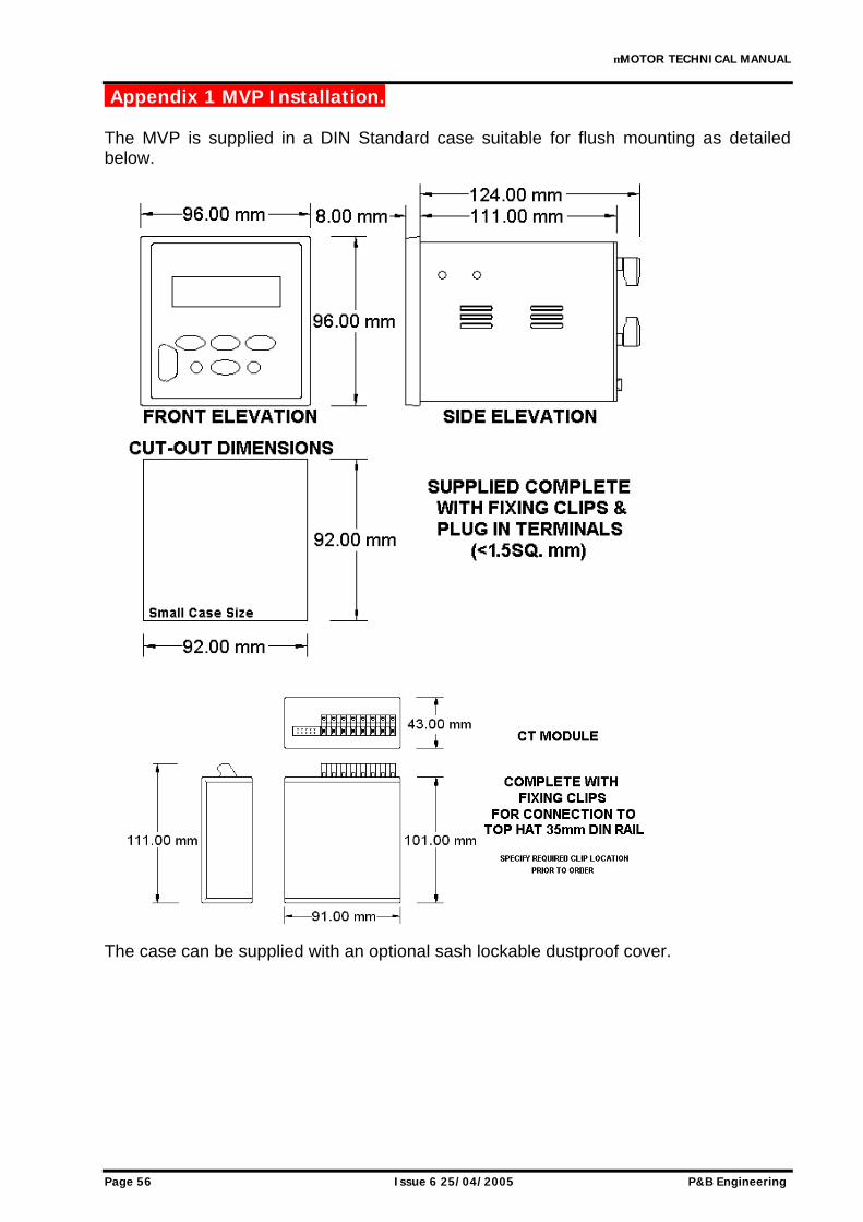
Appendix 1 MVP Installation. ................................................................................................................. 56 Appendix 2 Termination Numbers. ........................................................................................................ 57 Appendix 3 MVP Schematic Diagrams. ................................................................................................. 58 Appendix 4 Hall Effect Current Sensor Installation............................................................................ 59 Appendix 5 Thermal Overload Trip Times. ........................................................................................... 60 Appendix 6 Fast Scan Values. ................................................................................................................. 61 Appendix 7 Order Form / Code Structure............................................................................................. 62
µMOTOR TECHNICAL MANUAL
P&B Engineering Issue 6 25/04/2005 Page 1
1. P&B MICROVISIONPLUS, Motor Variant (µMOTOR). P&B Engineering's Microvision+ Motor Protection Controller is a highly sophisticated microprocessor based motor protection and control unit, specifically designed to be used as with 3-phase motors of full load currents below 15 Amps as an integral part of any type or manufacture of Motor Control Centres. Microvision+, due to its small size and innovative design, is able to fit in to the smallest of starter compartments. The CT (current transformer) module supplied is din rail mounted and rated at 1A, 2A, 5A or 15A covering a vast range of motor starters. All of the require features are included to allow flexible control, protection and monitoring of motor starters either by direct hard wired inputs and / or via the rear serial port, (RS485 or Profibus connection) with 1ms time stamping of events. The Microvision+ can be used to control Direct On Line, Star-Delta 2 & 3, Direct On Line Reversing, Air Circuit Breaker, DOL with Heater, Two Speed and Variable Speed Drive motor starters. Microvision+ monitors the current, voltage and optional temperature input to provide a comprehensive motor protection package. This is combined with all the necessary control and monitoring functions and a high-speed communication facility. The unit is a small, easily installed package supplied at a very competitive cost which makes this device the most attractive Motor Protection and Control device available today. All hard-wired control inputs are connected to the device via optically isolated inputs to enable all starting, stopping and tripping commands to be carried out by the unit. The status of all individual hard-wired contacts is also provided both locally via the two line liquid crystal display and remotely via any of the communication ports. All Setting parameters are programmed independently for each unit via the integral keypad and liquid crystal display on the front plate or via any of the communication ports and PC based software package available for the Vision II series of products. Microvision+ can be configured to support any motor starter application, protective functions can be individually configured to enable or disable the tripping and alarm functions. Tri-Colour Light Emitting Diodes mounted on the front plate give visual indication of the motor status i.e. ON / INHIBIT / OFF and ALARM / FAULTY / HEALTHY conditions. Flexible high speed control via PLC or DCS systems is obtained through the MV2’s communication ports, allowing computer access to full control and monitoring of motor data, including: running data, motor statistical data and control input status.
µMOTOR TECHNICAL MANUAL
Page 2 Issue 6 25/04/2005 P&B Engineering
1.1. Protective Functions. Max Start Time Protection Thermal Overload Protection with adjustable t6x and hot/cold ratio and fixed pre alarm Undercurrent Protection Load Increase Protection Low Set Overcurrent Protection Single Phase Protection Phase Unbalance Protection Undervoltage Protection Undervoltage Start Lockout Earth Fault Protection Optional PTC or NTC Thermistor or RTD Protection Excess Number of Starts Protection Short Circuit Protection Contactor Fault Protection Emergency Stop Protection Serial Timeout Protection Internal Error Protection Serial Inhibit Protection 5 External Semi-Customised Protection Settings
1.2. Displayed Drive Data. Average Amps Earth Fault Current Frequency Percentage Motor Load Voltage Percentage Thermal Capacity Motor Status Alarm Status Trip Status Inhibit Status Power kW Power Factor Temperature / Resistance (single channel) Test Mode
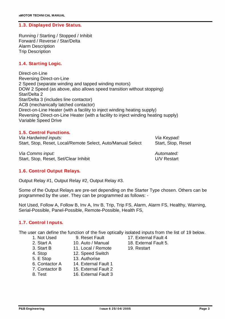
1.4. Starting Logic. Direct-on-Line Reversing Direct-on-Line 2 Speed (separate winding and tapped winding motors) DOW 2 Speed (as above, also allows speed transition without stopping) Star/Delta 2 Star/Delta 3 (includes line contactor) ACB (mechanically latched contactor) Direct-on-Line Heater (with a facility to inject winding heating supply) Reversing Direct-on-Line Heater (with a facility to inject winding heating supply) Variable Speed Drive
1.5. Control Functions. Via Hardwired inputs: Via Keypad: Start, Stop, Reset, Local/Remote Select, Auto/Manual Select Start, Stop, Reset Via Comms input: Automated: Start, Stop, Reset, Set/Clear Inhibit U/V Restart
1.6. Control Output Relays. Output Relay #1, Output Relay #2, Output Relay #3. Some of the Output Relays are pre-set depending on the Starter Type chosen. Others can be programmed by the user. They can be programmed as follows: - Not Used, Follow A, Follow B, Inv A, Inv B, Trip, Trip FS, Alarm, Alarm FS, Healthy, Warning, Serial-Possible, Panel-Possible, Remote-Possible, Health FS,
1.7. Control Inputs. The user can define the function of the five optically isolated inputs from the list of 19 below. 1. Not Used 9. Reset Fault 17. External Fault 4 2. Start A 10. Auto / Manual 18. External Fault 5. 3. Start B 11. Local / Remote 19. Restart 4. Stop 12. Speed Switch 5. E Stop 13. Authorise 6. Contactor A 14. External Fault 1 7. Contactor B 15. External Fault 2 8. Test 16. External Fault 3
µMOTOR TECHNICAL MANUAL
Page 4 Issue 6 25/04/2005 P&B Engineering
2. Technical Specification.
Power Supply.
AUXILIARY POWER SUPPLY & LOW VOLTAGE POWER SUPPLY AC Nominal Range 80 – 265V AC / DC
Range 24V AC / 24-48V DC (Low Voltage Power Supply Optional Extra) Frequency 45 - 65 Hz Maximum Power Consumption 10VA, 15VA Nominal
Measurement.
PHASE CURRENT MEASUREMENT Method True RMS, Sample time <1ms Range 0.1 to 16x Phase CT Primary Amps Full Scale 16 x Phase CT Primary Amps Setting Accuracy ± 3% at Phase CT Primary amps EARTH PHASE CURRENT MEASUREMENT Method True RMS, Sample time <1ms Range 0.05 to 2.0x E/F CT Primary Amps
Full Scale 2.0 x E/F CT Primary Amps Setting Display Accuracy ± 3% of Reading Over Range Pick Up accuracy ± 3% of setting VOLTAGE REFERENCE MEASUREMENT Suitable for connection preferably via isolating transformers (VT) or direct connection to max phase to phase system voltage not exceeding the rated voltage. Method True RMS, Sample time <1ms Rated Insulation Voltage 500V Range 100 – 500V AC Display Accuracy ± 3%
Power Accuracy ± 5% of Nominal VT Burden 0.01 VA THERMISTOR/RTD INPUT. Response Time < 0.5 seconds Thermistor Range 1 - 30 Kilo-Ohms Thermistor Accuracy ± 5% of reading or 100 ohms whichever is the greater RTD Range 0-250°C RTD Accuracy not greater than ± 7.7% of reading
Protection Functions.
OVERLOAD ALARM AND TRIP CURVES Fault Time Accuracy ± 200mS up to 10 seconds
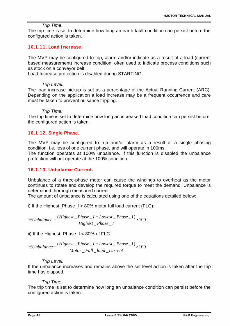
± 2% of trip time over 10 seconds Threshold Current Level Overload Setting ± 2% CURRENT UNBALANCE ALARM AND TRIP Method Unbalance = 100 x (Imax - Imin) / Ir %
Where Imax = max. of 3 phase currents Imin = min. of 3 phase currents Ir = Larger of Imax or Motor FLC
Alarm Threshold Unbalance Level 50% of Unbalance current ± 2% Alarm Fixed Time Delay Accuracy 1.0 ± 0.5 seconds Trip Threshold Unbalance Level Unbalance Current Setting ± 2% Trip Time Accuracy ± 1 second up to 10 seconds
± 1 second +/- 2% above 10 sec. TIME DELAYS Accuracy ± 0.5 seconds or ± 2% of time Exceptions Earth Fault Trip +150mS,-0.0@ 1.1 x setting
+60mS,-0.0@ 2 x setting +40mS,-0.0@ 5 x setting
Total Run Time Accuracy ± 2% Auto Restart delay on Restart Time ± 0.2 seconds
Relay Contacts Ratings.
OUTPUT RELAYS Rated Load 12A @ 277 AC
12A @ 28V DC Maximum Operating Voltage 330V AC Max Making Current 1.2A Max Breaking Current 100-200mA
µMOTOR TECHNICAL MANUAL
P&B Engineering Issue 6 25/04/2005 Page 5
3. Environmental Tests.
CLIMATIC TEST STANDARD SEVERITY LEVEL Temperature Dry Cold Operational
IEC 60068-2-1 -20 deg C ,96 hrs
Temperature Dry Cold Transportation & Storage
IEC 60068-2-1 -40 deg C , 96hrs
Temperature Dry Heat Operational
IEC 60068-2-2 +60 deg C , 96 hrs
Temperature Dry Heat Transportation & Storage
IEC 60068-2-2 +85 deg C , 96 hrs
Damp Heat Steady State
IEC 60068-2-30 95% Non-condensing, Cyclic Test Db
Enclosure IEC 60529 front IP52 , rear IP00 MECHANICAL Vibration IEC 60255-21-1 Class I Shock & Bump IEC 60255-21-2 Class I Seismic IEC 60255-21-3 Class I ELECTRICAL Insulation resistance IEC 60255-5 500 Vdc , 5 secs Dielectric Test IEC 60255-5 Series C of table 1
2.5 kV 50Hz , 1 min 1.0 kV open contacts , 1 min
High Voltage Impulse IEC 60255-5 5 kV peak 1.2/50uS,0.5J 3 pos , 3 neg
Voltage Dips , Short Interruptions & Voltage variations immunity
IEC 60255-11 IEC 61000-4-11
3 dips & 3 interruptions at 10 sec intervals of duration between 10mS and 500mS at zero crossings. Variations 40% &70%
Ripple in dc supply IEC 60255-11 12% ac ripple VT input Thermal Withstand 120% Vn , continuous CT input Thermal Withstand 250xIn half wave,100xIn for 1 second 30 xIn for 10 second ,
4 xIn cont. ELECTROMAGNETIC COMPATIBILITY Electrical fast Transient/Burst IEC 60255-22-4
IEC 61000-4-4 Class IV-4.0kv Power supply Class III -2.0 kV Other inputs 1 min each polarity
Oscillatory Waves 1 Mhz Burst
IEC 60255-22-1 Class III Longitudinal 2.5 kV , 2sec Transverse 1.0 kV , 2 sec
Electrostatic Discharge IEC 60255-22-2 Class III 8 kV contact 15kV air discharge , 10 discharges at 1 sec intervals
IEC 61000-4-8 1000A/m for 1 sec 100A/m for 1 minute
Pulse Magnetic Field IEC 61000-4-9 6.4/16uS , 1000A/m Damped Oscillatory Magnetic Field Immunity
IEC 61000-4-10 0.1 & 1.0 Mhz , 100A/m
Conducted & Radiated RF Interference Emission
EN55022 or EN55011or EN50081-2
Class A interference limits
Power frequency conducted immunity, common mode
IEC 61000-4-16 IEC 60255-22-7
DC to 150kHz sweep test level 4 300V at 16 2/3 & 50/60Hz
µMOTOR TECHNICAL MANUAL
Page 6 Issue 6 25/04/2005 P&B Engineering
4. Analogue Inputs.
4.1. Power Supply Live. The Microvision+ requires an AC or DC Voltage to supply the unit. A separate AC/DC voltage is required to supply the digital inputs (Control Supply), this can be taken from the Auxiliary Supply, or a completely isolated supply can be employed. The Microvision+ can also be fitted with a Low Voltage Power Supply (PSU) and / or Low Voltage digital inputs. The Microvision+ monitors the power supply assumed to be derived from the primary side of the contactor within the starter cubicle or from the MCC busbars to provide an Undervoltage Restart facility. When enabled in the Starter Settings page the Microvision+ monitors the supply and in the event of a failure will maintain the start signal to the motor for up to 200m seconds. Beyond 200m sec the unit will trip the motor and should the power supply be restored to 95% within the programmable Restart Time (2.0 to 200s) the unit will restart the motor after a programmable time delay (1-120s). Should the voltage not be restored within the programmable Restart Time the motor will not be automatically restarted. There is also a digital input that can be used to enable or block the Undervoltage Restart. If the input is closed then a restart can occur, if open, then the restart is blocked. If no digital input is set to Restart then a restart will always occur.
4.2. Voltage Reference. The Microvision+ monitors single phase voltage, which can be directly connected for voltages up to 500V. In order that the Microvision+ can measure and display the actual voltage, the phase to phase or phase to neutral input must be selected in the settings. A reverse feature has been included to allow incorrect phase connections to be rectified without the need to rewire. With the use of Voltage Transformer the Microvision+ can monitor voltages up to 22kV.
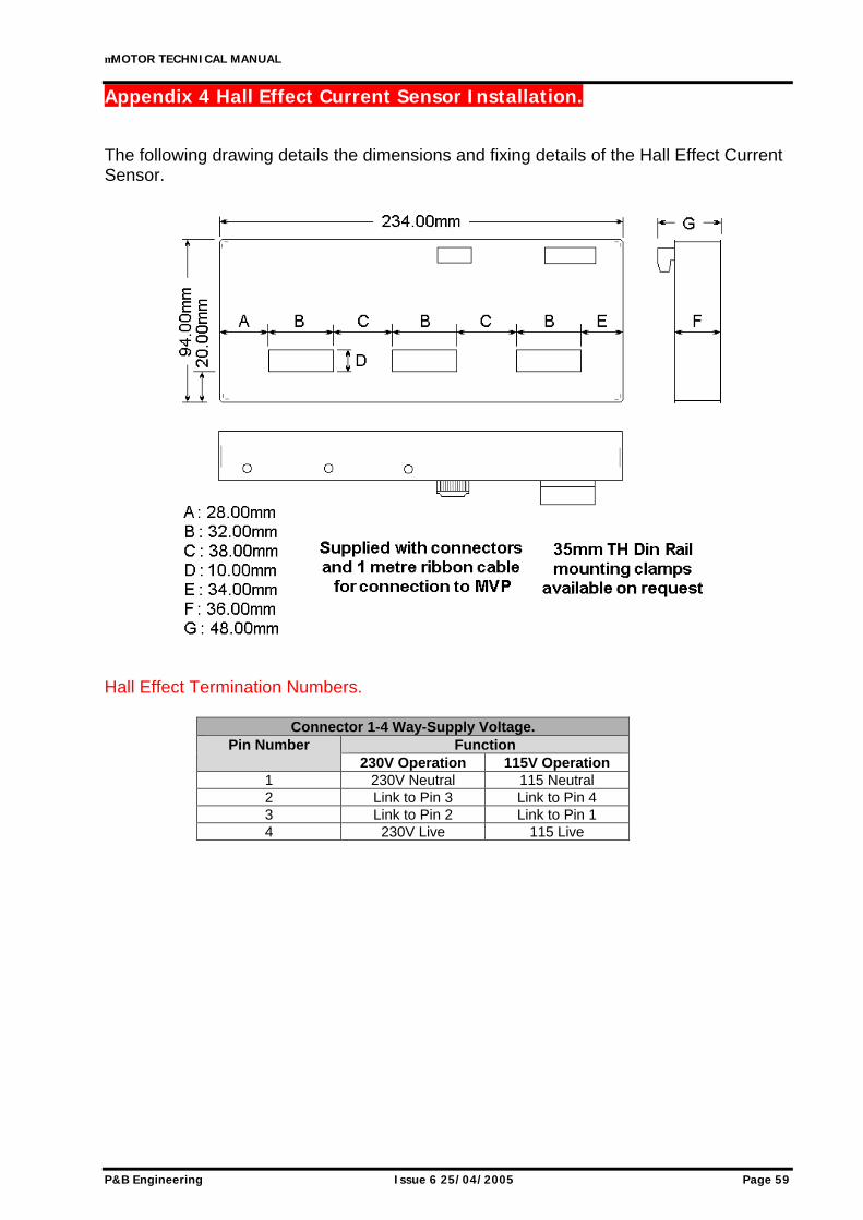
4.3. Current Sensor Inputs. The current inputs to the Microvision+ are housed in a separate module designed to help achieve the small size and form part of the integral starter cubicle. Available as either Conventional Current Transformers or Hall Effect Sensors. 4.3.1. Hall Effect Sensors. To allow MCC manufacturers to use the smallest size compartments P&B have developed an accurate Hall Effect Current Sensor. The unit is a compact 3 phase enclosed device. The Current Sensor comes complete with a ribbon cable and connectors to plug directly into the associated dedicated terminal block. See Appendix 4. The current sensor is available in 3 versions depending upon the calibrated rating for motor full load ratings of 10-25, 25-50 & 50-150 Amperes. To give maximum accuracy the sensors are normally calibrated to the actual drive current or cubicle rating prior to despatch. Earth fault protection can be achieved via a special internal residual earth fault or as standard, a separate 1A CT input is provided for Core Balance CT connection.
µMOTOR TECHNICAL MANUAL
P&B Engineering Issue 6 25/04/2005 Page 7
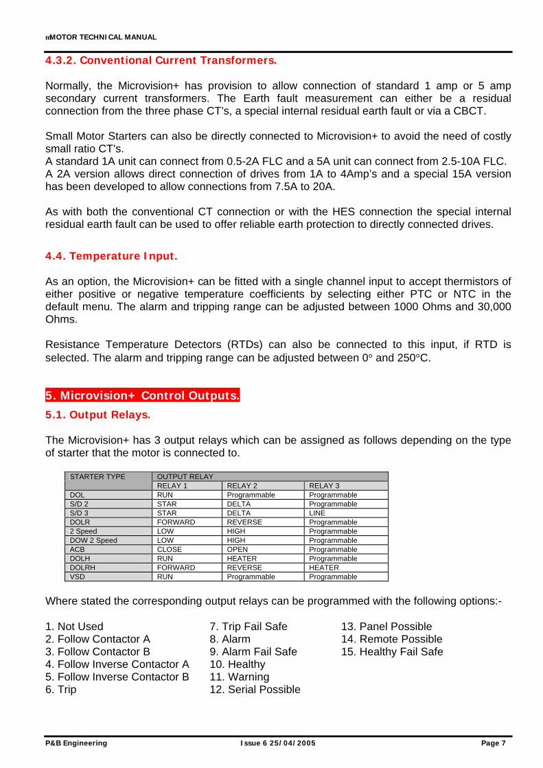
4.3.2. Conventional Current Transformers. Normally, the Microvision+ has provision to allow connection of standard 1 amp or 5 amp secondary current transformers. The Earth fault measurement can either be a residual connection from the three phase CT’s, a special internal residual earth fault or via a CBCT. Small Motor Starters can also be directly connected to Microvision+ to avoid the need of costly small ratio CT’s. A standard 1A unit can connect from 0.5-2A FLC and a 5A unit can connect from 2.5-10A FLC. A 2A version allows direct connection of drives from 1A to 4Amp’s and a special 15A version has been developed to allow connections from 7.5A to 20A. As with both the conventional CT connection or with the HES connection the special internal residual earth fault can be used to offer reliable earth protection to directly connected drives.
4.4. Temperature Input. As an option, the Microvision+ can be fitted with a single channel input to accept thermistors of either positive or negative temperature coefficients by selecting either PTC or NTC in the default menu. The alarm and tripping range can be adjusted between 1000 Ohms and 30,000 Ohms. Resistance Temperature Detectors (RTDs) can also be connected to this input, if RTD is selected. The alarm and tripping range can be adjusted between 0° and 250°C.
5. Microvision+ Control Outputs.
5.1. Output Relays. The Microvision+ has 3 output relays which can be assigned as follows depending on the type of starter that the motor is connected to.
OUTPUT RELAY STARTER TYPE RELAY 1 RELAY 2 RELAY 3
DOL RUN Programmable Programmable S/D 2 STAR DELTA Programmable S/D 3 STAR DELTA LINE DOLR FORWARD REVERSE Programmable 2 Speed LOW HIGH Programmable DOW 2 Speed LOW HIGH Programmable ACB CLOSE OPEN Programmable DOLH RUN HEATER Programmable DOLRH FORWARD REVERSE HEATER VSD RUN Programmable Programmable
Where stated the corresponding output relays can be programmed with the following options:- 1. Not Used 7. Trip Fail Safe 13. Panel Possible 2. Follow Contactor A 8. Alarm 14. Remote Possible 3. Follow Contactor B 9. Alarm Fail Safe 15. Healthy Fail Safe 4. Follow Inverse Contactor A 10. Healthy 5. Follow Inverse Contactor B 11. Warning 6. Trip 12. Serial Possible
µMOTOR TECHNICAL MANUAL
Page 8 Issue 6 25/04/2005 P&B Engineering
5.2. Relay Settings. Follow A. If an output relay is programmed as ‘Follow A’ its state will mirror the state of output relay 1. When a relay is programmed as ‘Follow A’ a delay may be assigned. Follow B. If an output relay is programmed as ‘Follow B’ its state will mirror the state of output relay 2. When a relay is programmed as ‘Follow B’ a delay may be assigned. Inverse A. If an output relay is assigned as ‘Inv. A’ its state will always be the inverse of the state of output relay 1. Inverse B. If an output relay is assigned as ‘Inv. B’ its state will always be the inverse of the state of output relay 2. Trip. If an output relay is assigned as ‘Trip’ then this relay will change state from the de-energised to the energised relay contact when triggered by any protection function or external device connected to the relay that is configured to trip the motor. Trip Fail Safe. If an output relay is assigned as ‘Trip FS’ (Trip Failsafe) then this relay will change state from energised to the de-energised relay contact when triggered by any protection function or external device connected to the relay that is configured to trip the motor.
µMOTOR TECHNICAL MANUAL
P&B Engineering Issue 6 25/04/2005 Page 9
Alarm. If an output relay is assigned as ‘Alarm’ then this relay will change state from de-energised to the energised relay contact when triggered by any protection function or external device connected to the relay that is configured to alarm. Alarm Fail Safe. If an output relay is assigned as ‘Alarm FS’ then this relay will change state from energised to the de-energised relay contact when triggered by any protection function or external device connected to the relay that is configured to alarm. Healthy. If an output relay is assigned as “Healthy” this relay will be in its de-energised state at all times while the unit reports the motor as being healthy. This relay will be energised when the unit registers either an Alarm or Fault condition or the motor has been inhibited from starting. Warning. If an output relay is assigned as ‘Warning’ then it will change state when any enabled protection function has exceeded its pickup value. The relay is not latching. When the pickup setting is no longer violated the output relay assigned as ‘Warning’ will be de-energised. The ‘Warning’ relay does not wait until the expiry of a trip or alarm timer before being energised. It will energise immediately after an enabled protection feature has its pickup point violated or a digital input registers a fault status. Serial Possible. If an output relay is assigned as ‘Serial Possible’ this relay will be energised only when the motor is available to be started through the serial port, via a serial command. For details on configuring possible start sources see sections 9.3.4.1. and 15. Panel Possible If an output relay is assigned as “Panel Possible” this relay will be energised only when the motor is available to be started from the front panel of the relay. For details on configuring possible start sources see sections 9.3.4.1. and 15. Remote Possible. If an output relay is assigned as ‘Remote Possible’ this relay will be energised only when the motor is available to be started from a remote station via a digital input. For details on configuring possible start sources see sections 9.3.4.1. and 15. Healthy Fail Safe. If an output relay is assigned as ‘Healthy FS’ (Healthy Failsafe) this relay will be in its energised state at all times while the unit reports the motor as being healthy. This relay will be de-energised when the unit registers either an Alarm or Fault condition or the motor has been inhibited from starting.
µMOTOR TECHNICAL MANUAL
Page 10 Issue 6 25/04/2005 P&B Engineering
6. Microvision+ Control Inputs. The Microvision+ offers 5 digital inputs to provide full control and indication for the motor starter. The supply to these terminals is derived from a separate Control Supply to the relay. As the digital inputs are completely isolated from the relays internal supply it is possible to have field input signals at a different voltage or phase from the relays’ auxiliary power supply. The 5 inputs are chosen by the user from the list described in the following sections.
6.1. Start A and Start B Inputs. When one of these inputs are closed the corresponding output relay is energised as long as the Start Setup Sources has been set accordingly (see sections 9.3.4.1. and 15), and provided all other External Faults are in the healthy state. Start A only is used for DOL, DOL Forward, Star or Low Speed contactors whilst Start B is used for DOL Reverse or High Speed. The starter settings menu allows these Start inputs to be either momentary, i.e. from push buttons or maintained, i.e. from PLC outputs not both.
6.2. Stop Input. If this input is open circuited the motor will be switched off and inhibited from starting as long as the Stop Setup Sources have been set to allow the stop to be active from the remote source. (see sections 9.3.4.1. and 15).
6.3. Emergency Stop. This input allows the Microvision+ to monitor the status and provide indication of the state of any of the external Emergency Stop buttons which are normally directly wired to the contactor closing circuit. Opening of the input causes a trip with an option to alarm depending on the Protection Settings. Emergency Stop is only disabled when used for contactor applications, (short circuit protection is also disabled) when the phase fault current exceeds 8 x In.
6.4. Contactor A and B Status. These status inputs from the contactors allow the Microvision to determine the status of both the A and B contactors, also known as Relays 1 and 2. Cont A is the feedback signal for a Start A command and Cont B is the feedback signal for a Start B command. Monitoring of these contacts also provides protection against 'Control Open' (when a Microvision+ START command is not confirmed by these inputs, Cont A and/or Cont B) and 'Welded Contact' (when Microvision+ STOP command is not confirmed by these inputs). Only when the Contactor Fault protection is enabled do these ‘active faults’ appear under warranted situations.
µMOTOR TECHNICAL MANUAL
P&B Engineering Issue 6 25/04/2005 Page 11
6.5. Test Mode. When in the Test mode the Microvision+ will disable Undercurrent Protection, Undervoltage, Single Phase and Phase Sequence protection functions, as well as the External Faults if set to Disable in Test. This allows full functional testing to be performed without the need for voltage or current injection and will allow secondary injection testing to be carried out on all protective functions except for those disabled by the feature.
6.6. Reset Fault. This input enables the operator to reset a Microvision Plus Fault or Alarm condition. The Input can only perform a reset if the following conditions are met: 1. The Protection Settings for the specific fault or alarm are set to allow remote resets. 2. The condition that caused the Fault or Alarm to occur no longer exists. Providing conditions 1 and 2 are met an operator can override the settings in the Protection Settings by closing the Authorise digital input and pressing the Reset digital input.
6.7. Auto/Manual and Local/Remote Inputs. These inputs are used to determine the source of both the Start Signal and Stop Signal to the motor. They are configured in the Start Setup Source and the Stop Setup Source. (See sections 9.3.4.1. and 15)
6.8. Speed Switch. Closing of this input reduces the trip time on the cold and hot curves by 50%. A tachometer is generally used on the rotor to determine if the shaft is turning the transducer is fed to this input. This provides a faster trip for stalled motors.
6.9. Authorise. This function can be programmed as a digital input to allow a physical key switch to override the password and reset all faults. This input can be used to restrict fault and alarm reset, if the Auto and Panel reset options of protective functions are disabled a fault can only be reset from the panel if the authorised input is closed. The use of the "Authorise" function will override the password. All data menus, display scroll and drive control are accessible without requiring the use of the "Authorise" or "Password" functions if these are enabled. Should a digital input be set to Authorise then the user will be unable to Disable the Password Setting on the relay. To Disable the password the Authorise input must be assigned as another digital input or set to ‘Not Used’.
µMOTOR TECHNICAL MANUAL
Page 12 Issue 6 25/04/2005 P&B Engineering
6.10. External Faults 1-5. The flexibility of the External Fault inputs gives Microvision+ an intelligent PLC aspect to protective relaying. External Faults are voltage based and are assigned to digital inputs to perform a wide variety of roles. Multiple plant interlocking, process shutdown or for use as a gateway onto the serial network for digital signals via the Microvision+. External Faults can be configured as independent protective functions and can be configured to any combination of; Trip, Alarm, Inhibit or just to Stop the drive. The normal reset types are available; Auto, Panel, Serial and Remote. The fault status of the input is programmable such that OFF = Fault or ON = Fault where the input is fed from either a normally closed (NC) or normally open (NO) source. The trip time (or time to take the configured action) is settable in the range 1 to 60 seconds. Each External Fault text string (EXTERNAL 1 etc) can be reconfigured to any character and numerical string desired via any of the serial ports.
6.11. Restart. This input will inhibit or permit an Undervoltage Restart to take place. This is to allow the differentiation between power losses that would and would not allow an automated restart of the drive. If the input is closed a restart can occur and if the input is open then the restart will be blocked. If no digital input is set to Restart then an Undervoltage Restart would always occur, if enabled.
µMOTOR TECHNICAL MANUAL
P&B Engineering Issue 6 25/04/2005 Page 13
7. MV2 Serial Ports.
7.1. RS485 The Serial Port supplied with Microvision+ as standard utilises a half duplex RS485 protocol allowing up to 32 units to be daisy-chained together, or to be multi-drop connected with a single shielded twisted pair cable. The Microvision+ in addition to its very comprehensive protection and control features has been equipped with a very powerful data communications system. This extends its boundaries far beyond a motor protection controller into the realms of a complete motor management system. It provides high-speed data acquisition to supervisory computers to form a complete motor management system. Each Microvision+ can be connected to an isolated data highway using RS485 communications. Up to 32 units can be connected to each data highway. The host system can interrogate the unit to monitor motor status, running conditions, historical data and fault data as well as control functions such as a start and stop to the motor and reset fault / alarm conditions. The Microvision+ is available with P&B network gold (P&B protocol) installed for use with the Xcell Data Concentrator for fully Integrated Protection, Control & Monitoring Systems with full dual redundancy or with a Slave implementation of Modbus RTU protocol for small systems and direct Modbus access to devices where data concentration is not required.
7.2. Profibus The Microvision+ can also be fitted with a standard 9-way d-type connector in place of the RS485 connection to provide a Profibus DP interface. See section 12.1.
7.3. RS232 The unit is additionally fitted with a front mounted RS232 port to allow relay interface using the P&B Protocol regardless of the rear port configuration. Full details of the protocols, device mapping, gds files and other support documents are available on request. Information on the Xcell Data Concentrator is contained in the P&B Integrated Protection & Control System Integrators Manual, available on request.
µMOTOR TECHNICAL MANUAL
Page 14 Issue 6 25/04/2005 P&B Engineering
8. Microvision+ Faceplate Functions. The MV2 Faceplate has been designed to allow Motor Control and to provide display and access to a data parameters, viewing and changing of setting parameters, trip and alarm messages. This is achieved by using 2 tri-colour LED’s, a two line LCD display and 4 software driven function keys that change function depending upon which page of the menu structure is being viewed. This eliminates the need for additional indication devices on the front of the motor starter panel such as Lamps, Ammeter, Voltmeter, Hours Run Indicator, Operations Counter, etc. which helps reduce the cost of the motor starter panel and gives improved reliability by the reduction of separate components.
The up and down buttons allow the display to scroll through the measured values and devices status. When updating firmware the unit can be forced in the program mode by holding down both the up and down arrow buttons as the unit is powered on. The unit can be updated using the rear RS485 port if fitted, or the front RS232 port.
8.1. LED Status. The LED's operate as follows:
LED Colour
Left LED [Drive Status]
Right LED [Fault Status]
Green Off Healthy Yellow Inhibited Alarm
Red On Fault
µMOTOR TECHNICAL MANUAL
P&B Engineering Issue 6 25/04/2005 Page 15
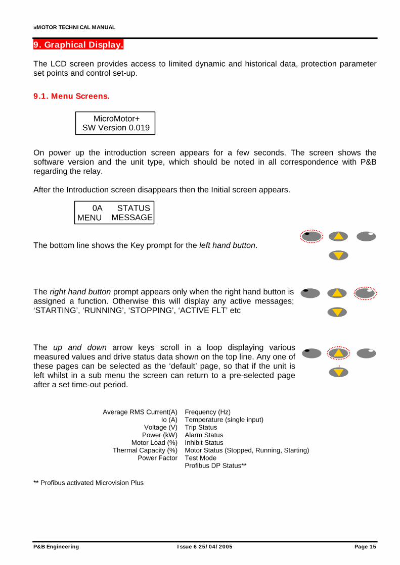
9. Graphical Display. The LCD screen provides access to limited dynamic and historical data, protection parameter set points and control set-up.
9.1. Menu Screens. On power up the introduction screen appears for a few seconds. The screen shows the software version and the unit type, which should be noted in all correspondence with P&B regarding the relay. After the Introduction screen disappears then the Initial screen appears. The bottom line shows the Key prompt for the left hand button. The right hand button prompt appears only when the right hand button is assigned a function. Otherwise this will display any active messages; ‘STARTING’, ‘RUNNING’, ‘STOPPING’, ‘ACTIVE FLT’ etc The up and down arrow keys scroll in a loop displaying various measured values and drive status data shown on the top line. Any one of these pages can be selected as the ‘default’ page, so that if the unit is left whilst in a sub menu the screen can return to a pre-selected page after a set time-out period.
Average RMS Current(A) Frequency (Hz)
Io (A) Temperature (single input) Voltage (V) Trip Status
Power (kW) Alarm Status Motor Load (%) Inhibit Status
Thermal Capacity (%) Motor Status (Stopped, Running, Starting) Power Factor Test Mode
Profibus DP Status** ** Profibus activated Microvision Plus
MicroMotor+SW Version 0.019
0AMENU
STATUSMESSAGE
µMOTOR TECHNICAL MANUAL
Page 16 Issue 6 25/04/2005 P&B Engineering
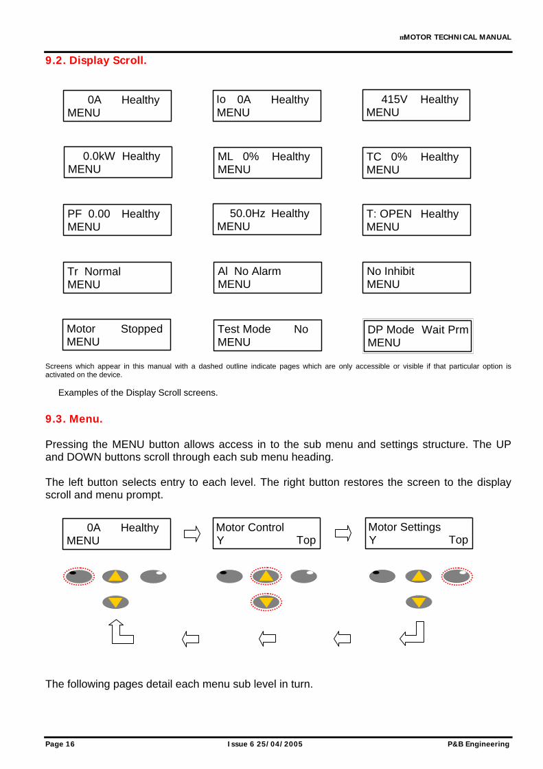
9.2. Display Scroll. Screens which appear in this manual with a dashed outline indicate pages which are only accessible or visible if that particular option is activated on the device.
Examples of the Display Scroll screens.
9.3. Menu. Pressing the MENU button allows access in to the sub menu and settings structure. The UP and DOWN buttons scroll through each sub menu heading. The left button selects entry to each level. The right button restores the screen to the display scroll and menu prompt. The following pages detail each menu sub level in turn.
0AMENU
Healthy 0AMENU
HealthyIo 415VMENU
Healthy
ML 0%MENU
Healthy TC 0%MENU
Healthy
PF 0.00MENU
Healthy 50.0HzMENU
Healthy T: OPENMENU
Healthy
Tr NormalMENU
Al No AlarmMENU
No InhibitMENU
MotorMENU
Stopped Test ModeMENU
No DP ModeMENU
Wait Prm
0AMENU
Healthy Motor ControlY Top
Motor SettingsY Top
0.0kWMENU
Healthy
µMOTOR TECHNICAL MANUAL
P&B Engineering Issue 6 25/04/2005 Page 17
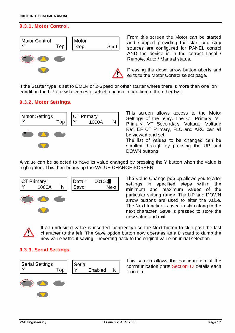
9.3.1. Motor Control.
From this screen the Motor can be started and stopped providing the start and stop sources are configured for PANEL control AND the device is in the correct Local / Remote, Auto / Manual status. Pressing the down arrow button aborts and exits to the Motor Control select page.
If the Starter type is set to DOLR or 2-Speed or other starter where there is more than one ‘on’ condition the UP arrow becomes a select function in addition to the other two. 9.3.2. Motor Settings.
This screen allows access to the Motor Settings of the relay. The CT Primary, VT Primary, VT Secondary, Voltage, Voltage Ref, EF CT Primary, FLC and ARC can all be viewed and set. The list of values to be changed can be scrolled through by pressing the UP and DOWN buttons.
A value can be selected to have its value changed by pressing the Y button when the value is highlighted. This then brings up the VALUE CHANGE SCREEN
The Value Change pop-up allows you to alter settings in specified steps within the minimum and maximum values of the particular setting range. The UP and DOWN arrow buttons are used to alter the value. The Next function is used to skip along to the next character. Save is pressed to store the new value and exit.
If an undesired value is inserted incorrectly use the Next button to skip past the last character to the left. The Save option button now operates as a Discard to dump the new value without saving – reverting back to the original value on initial selection.
9.3.3. Serial Settings.
This screen allows the configuration of the communication ports Section 12 details each function.
Motor ControlY Top
MotorStop Start
CT PrimaryY N1000A
Motor SettingsY Top
CT PrimaryY N1000A
Data =Save Next
001000
Serial SettingsY Top
SerialY NEnabled
µMOTOR TECHNICAL MANUAL
Page 18 Issue 6 25/04/2005 P&B Engineering
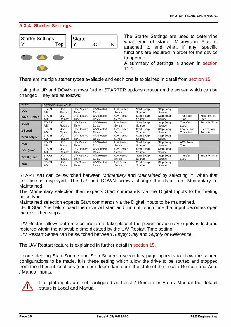
9.3.4. Starter Settings.
The Starter Settings are used to determine what type of starter Microvision Plus is attached to and what, if any, specific functions are required in order for the device to operate. A summary of settings is shown in section 11.1.
There are multiple starter types available and each one is explained in detail from section 15 Using the UP and DOWN arrows further STARTER options appear on the screen which can be changed. They are as follows;
TYPE OPTIONS AVAILABLE
DOL START A/B
U/V Restart
U/V Restart Time
U/V Restart Delay
U/V Restart Sense
Start Setup Source
Stop Setup Source
S/D 2 or S/D 3 START A/B
U/V Restart
U/V Restart Time
U/V Restart Delay
U/V Restart Sense
Start Setup Source
Stop Setup Source
Transition Time
Max Time In Star
DOLR START A/B
U/V Restart
U/V Restart Time
U/V Restart Delay
U/V Restart Sense
Start Setup Source
Stop Setup Source
Transfer Lock
Transfer Time
2-Speed START A/B
U/V Restart
U/V Restart Time
U/V Restart Delay
U/V Restart Sense
Start Setup Source
Stop Setup Source
Low to High Transition
High to Low Transition
DOW 2-Speed START A/B
U/V Restart
U/V Restart Time
U/V Restart Delay
U/V Restart Sense
Start Setup Source
Stop Setup Source
ACB START A/B
U/V Restart
U/V Restart Time
U/V Restart Delay
U/V Restart Sense
Start Setup Source
Stop Setup Source
ACB Pulse Time
DOL (Heat) START A/B
U/V Restart
U/V Restart Time
U/V Restart Delay
U/V Restart Sense
Start Setup Source
Stop Setup Source
DOLR (Heat) START A/B
U/V Restart
U/V Restart Time
U/V Restart Delay
U/V Restart Sense
Start Setup Source
Stop Setup Source
Transfer Lock
Transfer Time
VSD START A/B
U/V Restart
U/V Restart Time
U/V Restart Delay
U/V Restart Sense
Start Setup Source
Stop Setup Source
START A/B can be switched between Momentary and Maintained by selecting ‘Y’ when that text line is displayed. The UP and DOWN arrows change the data from Momentary to Maintained. The Momentary selection then expects Start commands via the Digital Inputs to be fleeting pulse type. Maintained selection expects Start commands via the Digital Inputs to be maintained. I.E. If Start A is held closed the drive will start and run until such time that input becomes open the drive then stops. U/V Restart allows auto reacceleration to take place if the power or auxiliary supply is lost and restored within the allowable time dictated by the U/V Restart Time setting. U/V Restart Sense can be switched between Supply Only and Supply or Reference. The U/V Restart feature is explained in further detail in section 15. Upon selecting Start Source and Stop Source a secondary page appears to allow the source configurations to be made. It is these setting which allow the drive to be started and stopped from the different locations (sources) dependant upon the state of the Local / Remote and Auto / Manual inputs.
If digital inputs are not configured as Local / Remote or Auto / Manual the default status is Local and Manual.
Starter SettingsY Top
StarterY NDOL
µMOTOR TECHNICAL MANUAL
P&B Engineering Issue 6 25/04/2005 Page 19
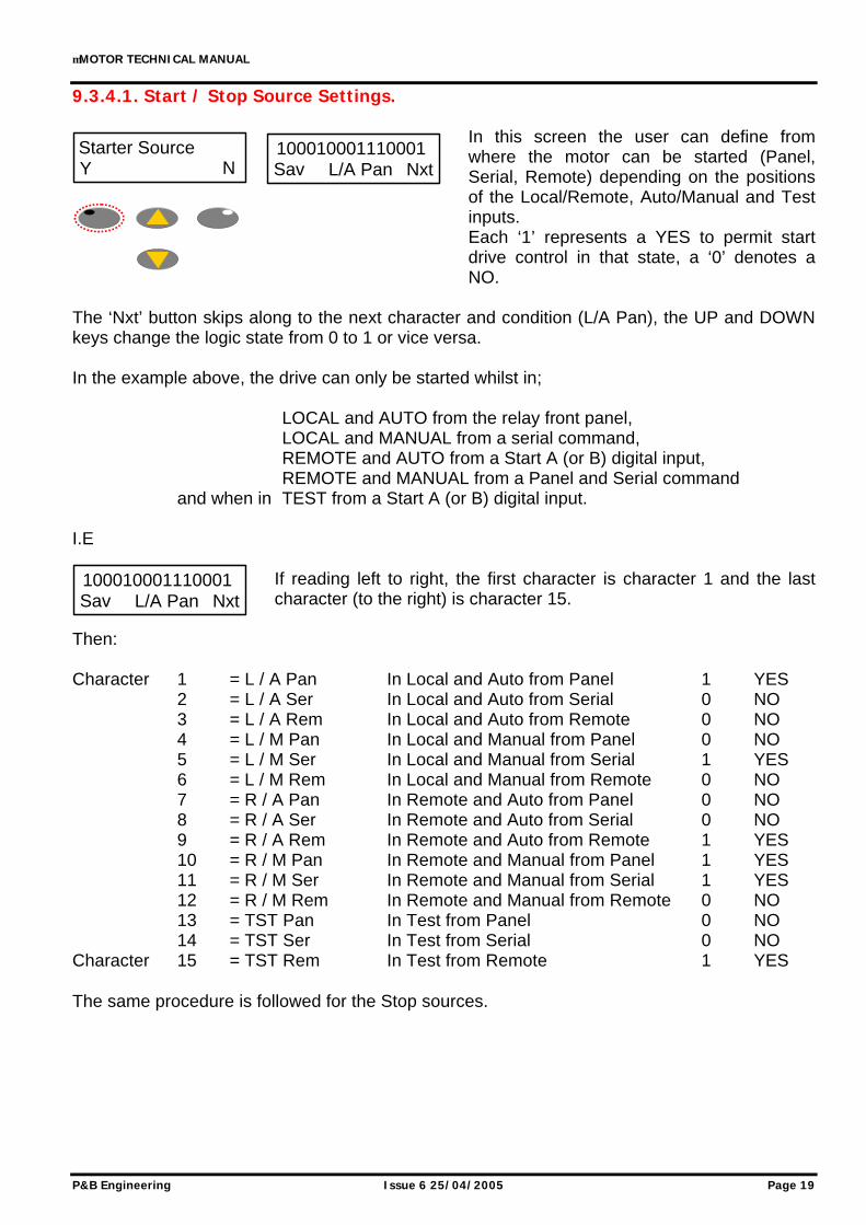
9.3.4.1. Start / Stop Source Settings.
In this screen the user can define from where the motor can be started (Panel, Serial, Remote) depending on the positions of the Local/Remote, Auto/Manual and Test inputs. Each ‘1’ represents a YES to permit start drive control in that state, a ‘0’ denotes a NO.
The ‘Nxt’ button skips along to the next character and condition (L/A Pan), the UP and DOWN keys change the logic state from 0 to 1 or vice versa. In the example above, the drive can only be started whilst in; LOCAL and AUTO from the relay front panel, LOCAL and MANUAL from a serial command, REMOTE and AUTO from a Start A (or B) digital input, REMOTE and MANUAL from a Panel and Serial command and when in TEST from a Start A (or B) digital input. I.E
If reading left to right, the first character is character 1 and the last character (to the right) is character 15.
Then: Character 1 = L / A Pan In Local and Auto from Panel 1 YES 2 = L / A Ser In Local and Auto from Serial 0 NO 3 = L / A Rem In Local and Auto from Remote 0 NO 4 = L / M Pan In Local and Manual from Panel 0 NO 5 = L / M Ser In Local and Manual from Serial 1 YES 6 = L / M Rem In Local and Manual from Remote 0 NO 7 = R / A Pan In Remote and Auto from Panel 0 NO 8 = R / A Ser In Remote and Auto from Serial 0 NO 9 = R / A Rem In Remote and Auto from Remote 1 YES 10 = R / M Pan In Remote and Manual from Panel 1 YES 11 = R / M Ser In Remote and Manual from Serial 1 YES 12 = R / M Rem In Remote and Manual from Remote 0 NO 13 = TST Pan In Test from Panel 0 NO 14 = TST Ser In Test from Serial 0 NO Character 15 = TST Rem In Test from Remote 1 YES The same procedure is followed for the Stop sources.
Starter SourceY N
100010001110001Sav NxtL/A Pan
100010001110001Sav NxtL/A Pan
µMOTOR TECHNICAL MANUAL
Page 20 Issue 6 25/04/2005 P&B Engineering
9.3.5. Current Options.
This sub menu allows the user to configure all of the current based protective functions:
< Current Under Current > Current Over Current Earth Flt Earth Fault Load Inc Load Increase Sgl Phase Single Phase Unbal. Unbalance Short Circ. Short circuit
Each function can be set to Alarm and / or Trip or left as an unused function, disabled. The resets for each are independently configurable as are the trip levels and trip times. The reset options are as follows;
Using the UP and DOWN keys the data can be changed to one of the following;
Panel Panel reset only Serial Serial reset only S P Serial or Panel reset Remote Remote reset only R P Remote or Panel reset R S Remote or Serial reset R S P Remote or Serial or Panel reset AUTO Auto reset
Each protective function and the settable options are explained in summary form and in detail in sections 11.2 and 16 respectively. 9.3.6. Voltage Options.
This sub menu allows all of the voltage based protective functions to be configured. < Voltage Under Voltage U/V Lockout Under voltage lockout > Voltage Over Voltage
As with the current based functions each voltage based protective function can be independently set to Alarm and / or Trip with adjustable threshold levels, timers and resets. With the exclusion of the U/V lockout protection where the available action is either left DISABLED or it is ENABLED which automatically causes an instantaneous inhibit when the voltage drops below its threshold level. Each protective function and the settable options are explained in summary form and in detail in sections 11.2 and 16 respectively.
Current OptionsY Top
< Current ActionY NDISABLED
< Current ResetY NDISABLED
DATA=DISABLEDSave Discard
Voltage OptionsY Top
< Voltage ActionY NDISABLED
µMOTOR TECHNICAL MANUAL
P&B Engineering Issue 6 25/04/2005 Page 21
9.3.7. Motor Options.
The Motor Options menu allows the configuration of other protective functions which are not specifically current or voltage based; StartTime Maximum Start Time Thermal Thermal model protection Too Many Starts Too Many Starts Contactor Fault Contactor feedback fault Em Stop Emergency Stop input
Each protective function and the settable options are explained in summary form and in detail in sections 11.2 and 16 respectively. 9.3.8. External Fault Options.
The Microvision Plus has 5 configurable external fault digital inputs which are configured under this heading. In order to operate correctly a digital input must also be assigned in the I/O Settings (see section 6). The External Faults can be configured to
behave as required and are generally activated from either a normally open (NO) or normally closed (NC) input. Each External Fault can be configured in the following way;
By using the UP and DOWN buttons the configurable action options are: DISABLED function is unused ALARM causes the unit to alarm TRIP causes the unit to trip ALARM&TRIP causes both an alarm &
a trip to occur
The Reset Action is configured in the normal, see section 9.3.5 for as an example. The External Fault can also be set to function as a drive inhibit or simply as a ‘healthy’ stop. It can also be configured to ignore the state of the External fault input when in the test mode. E.G.
Using the UP and DOWN buttons the follow options can be set: None no further config other than alarm/trip Test ignore status when in test mode Inhibit inhibit drive when active Inh Test as above and ignore status in test Stop stop the drive only S T as above and ignore status in test S I stop and inhibit S I T as above and ignore status in test
The trip time and polarity can also be set, see sections 11.2 and 16.1.18 for a full explanation.
Motor OptionsY Top
StartTime ActionY NALARM&TRIP
Ext Fault OptionY Top
Ext Flt 1 ActionY NTRIP
Ext Flt 1 ActionY NTRIP
DATA=TRIPSave Discard
Stop / InhibitY NInh Test
DATA=Inh TestSave Discard
µMOTOR TECHNICAL MANUAL
Page 22 Issue 6 25/04/2005 P&B Engineering
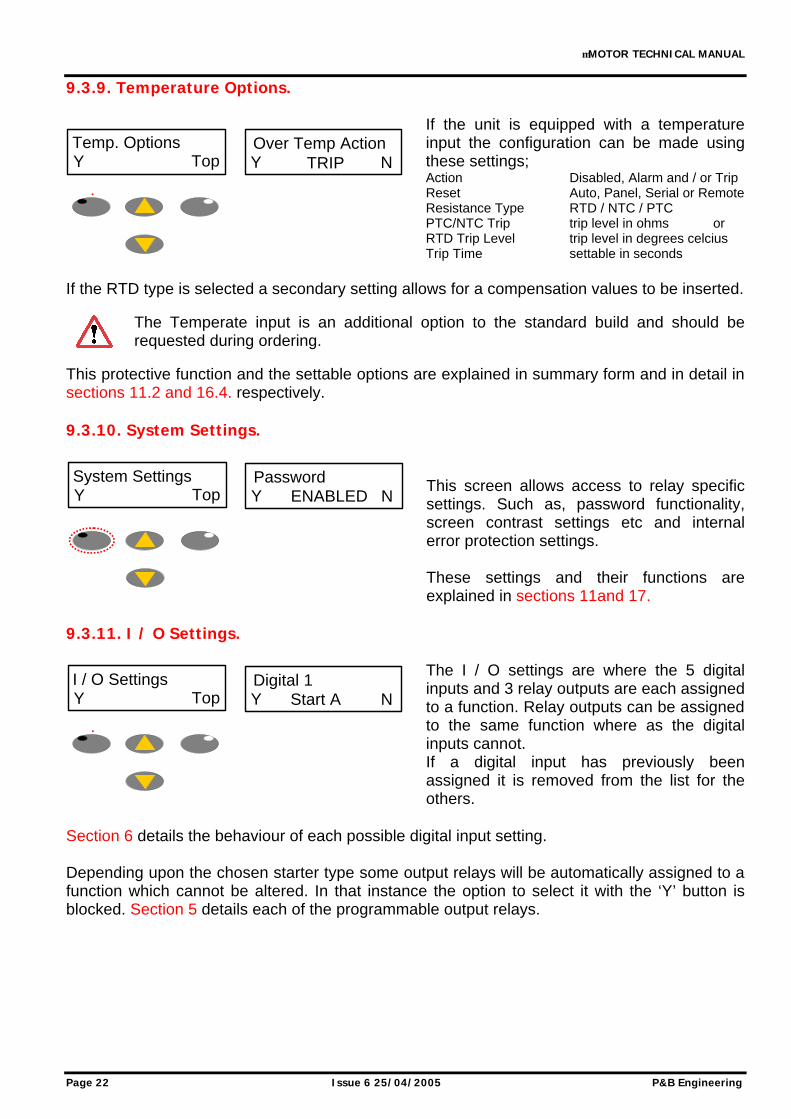
9.3.9. Temperature Options.
If the unit is equipped with a temperature input the configuration can be made using these settings; Action Disabled, Alarm and / or Trip Reset Auto, Panel, Serial or Remote Resistance Type RTD / NTC / PTC PTC/NTC Trip trip level in ohms or RTD Trip Level trip level in degrees celcius Trip Time settable in seconds
If the RTD type is selected a secondary setting allows for a compensation values to be inserted.
The Temperate input is an additional option to the standard build and should be requested during ordering.
This protective function and the settable options are explained in summary form and in detail in sections 11.2 and 16.4. respectively. 9.3.10. System Settings.
This screen allows access to relay specific settings. Such as, password functionality, screen contrast settings etc and internal error protection settings. These settings and their functions are explained in sections 11and 17.
9.3.11. I / O Settings.
The I / O settings are where the 5 digital inputs and 3 relay outputs are each assigned to a function. Relay outputs can be assigned to the same function where as the digital inputs cannot. If a digital input has previously been assigned it is removed from the list for the others.
Section 6 details the behaviour of each possible digital input setting. Depending upon the chosen starter type some output relays will be automatically assigned to a function which cannot be altered. In that instance the option to select it with the ‘Y’ button is blocked. Section 5 details each of the programmable output relays.
Temp. OptionsY Top
Over Temp ActionY NTRIP
System SettingsY Top
PasswordY NENABLED
I / O SettingsY Top
Digital 1Y NStart A
µMOTOR TECHNICAL MANUAL
P&B Engineering Issue 6 25/04/2005 Page 23
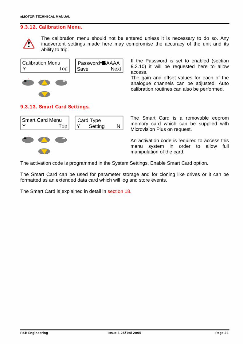
9.3.12. Calibration Menu.
The calibration menu should not be entered unless it is necessary to do so. Any inadvertent settings made here may compromise the accuracy of the unit and its ability to trip.
If the Password is set to enabled (section 9.3.10) it will be requested here to allow access. The gain and offset values for each of the analogue channels can be adjusted. Auto calibration routines can also be performed.
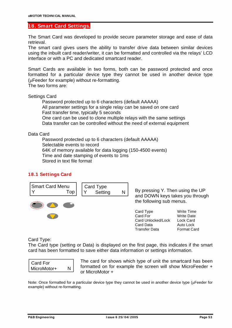
9.3.13. Smart Card Settings.
The Smart Card is a removable eeprom memory card which can be supplied with Microvision Plus on request. An activation code is required to access this menu system in order to allow full manipulation of the card.
The activation code is programmed in the System Settings, Enable Smart Card option. The Smart Card can be used for parameter storage and for cloning like drives or it can be formatted as an extended data card which will log and store events. The Smart Card is explained in detail in section 18.
Calibration MenuY Top
Password=AAAAASave Next
Smart Card MenuY Top
Card TypeY NSetting
µMOTOR TECHNICAL MANUAL
Page 24 Issue 6 25/04/2005 P&B Engineering
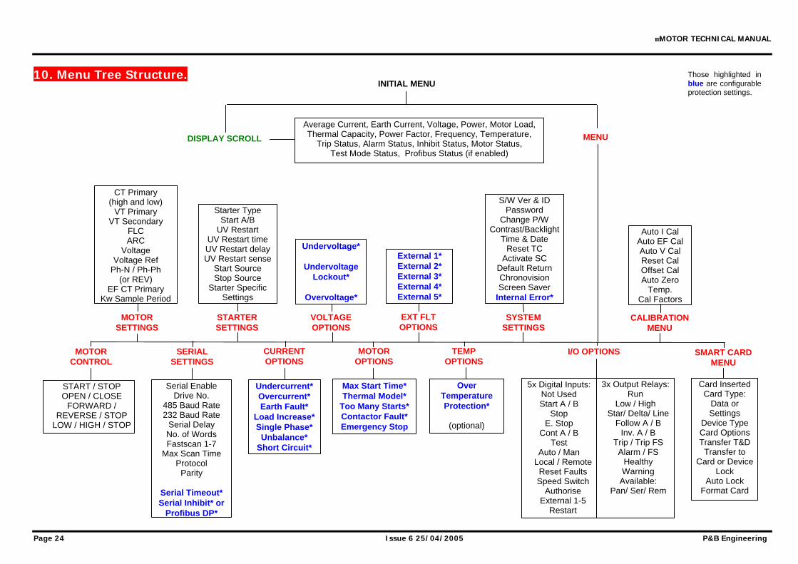
10. Menu Tree Structure.
Average Current, Earth Current, Voltage, Power, Motor Load, Thermal Capacity, Power Factor, Frequency, Temperature,
Trip Status, Alarm Status, Inhibit Status, Motor Status, Test Mode Status, Profibus Status (if enabled)
Undercurrent* Overcurrent* Earth Fault*
Load Increase* Single Phase*
Unbalance* Short Circuit*
START / STOP OPEN / CLOSE
FORWARD / REVERSE / STOP
LOW / HIGH / STOP
5x Digital Inputs: Not Used Start A / B
Stop E. Stop
Cont A / B Test
Auto / Man Local / Remote
Reset Faults Speed Switch
Authorise External 1-5
Restart
3x Output Relays: Run
Low / High Star/ Delta/ Line
Follow A / B Inv. A / B
Trip / Trip FS Alarm / FS
Healthy Warning
Available: Pan/ Ser/ Rem
MOTOR CONTROL
SERIAL SETTINGS
MOTOR SETTINGS
CT Primary (high and low)
VT Primary VT Secondary
FLC ARC
Voltage Voltage Ref
Ph-N / Ph-Ph (or REV)
EF CT Primary Kw Sample Period
Serial Enable Drive No.
485 Baud Rate 232 Baud Rate
Serial Delay No. of Words Fastscan 1-7
Max Scan Time Protocol
Parity
Serial Timeout* Serial Inhibit* or
Profibus DP*
Card Inserted Card Type:
Data or Settings
Device Type Card Options Transfer T&D
Transfer to Card or Device
Lock Auto Lock
Format Card
CURRENT OPTIONS
STARTER SETTINGS
MOTOR OPTIONS
VOLTAGE OPTIONS
DISPLAY SCROLL
INITIAL MENU
MENU
CALIBRATION MENU
TEMP OPTIONS
I/O OPTIONS
SYSTEM SETTINGS
EXT FLT OPTIONS
SMART CARD MENU
Max Start Time* Thermal Model*
Too Many Starts* Contactor Fault* Emergency Stop
Over Temperature Protection*
(optional)
Starter Type Start A/B
UV Restart UV Restart time UV Restart delay UV Restart sense
Auto I Cal Auto EF Cal Auto V Cal Reset Cal Offset Cal Auto Zero
Temp. Cal Factors
Those highlighted in blue are configurable protection settings.
µMOTOR TECHNICAL MANUAL
P&B Engineering Issue 6 25/04/2005 Page 25
11. Microvision Plus Settings Summary. The following pages show a summary all of the Microvision Plus Setting Pages and give the setting range and default setting. Each setting is then explained in detail.
Range Steps Default
Serial Enabled / Disabled 1s EnabledDrive Number 1-32 (125 Profibus) 1 1RS485 Baud Rate 9600/19200/38400 9600RS232 Baud Rate 4800/9600 4msSerial Delay 1ms-250ms 1ms 1msFast Scan Words 4 Words / 6 Words / 8 Words 4 WordsFastscan Analogue 1 0-254 2 0Fastscan Analogue 2 0-254 2 0Fastscan Analogue 3 0-254 2 0Fastscan Analogue 4 0-254 2 0Fastscan Analogue 5 0-254 2 0Fastscan Analogue 6 0-254 2 0Fastscan Analogue 7 0-254 2 0Max Fast Scan 1-30s 1s 2sSerial Protocol Modbus / P&B Standard P&B StandardParity Even / Odd / None Even
#L -> H Transfer 1 - 250s 1s 0s#H -> L Transfer 1 - 250s 1s 0s#Low to High Enabled / Disabled Disabled#High to Low Enabled / Disabled Disabled!Transition Time 0.04 - 2.00 0.01s 0.20s!Max. Time in Star 1 - 250s 1s 1s
!Stay in Star NO / YES NO%Transfer Lock Enabled / Disabled Disabled%Transfer Time 1 - 300s 1s 1s"ACB Pulse Time 0 - 200s 1s 0s
#2-Speed starter only!Star / Delta starter only%DOL with Reverse"ACB only
Digital InputsInput 1 - 5 Not Used / Start A / Start B / Stop / E.
Stop / Cont. A / Cont. B / Test / Reset Fault / Auto/Man / Loc/Rem / Spd Switch / Authorise / External 1 - 5 / Restart
Not Used
Relay Outputs
Output 1RUN / STAR / FORWARD / LOW / CLOSE RUN
Output 2
DELTA / REVERSE / HIGH / OPEN / HEATER / Not Used / Programmable
Not Used
Output 3LINE / HEATER / Not Used / Programmable Not Used
Starter Settings:
I/O Options:
µMOTOR TECHNICAL MANUAL
P&B Engineering Issue 6 25/04/2005 Page 27
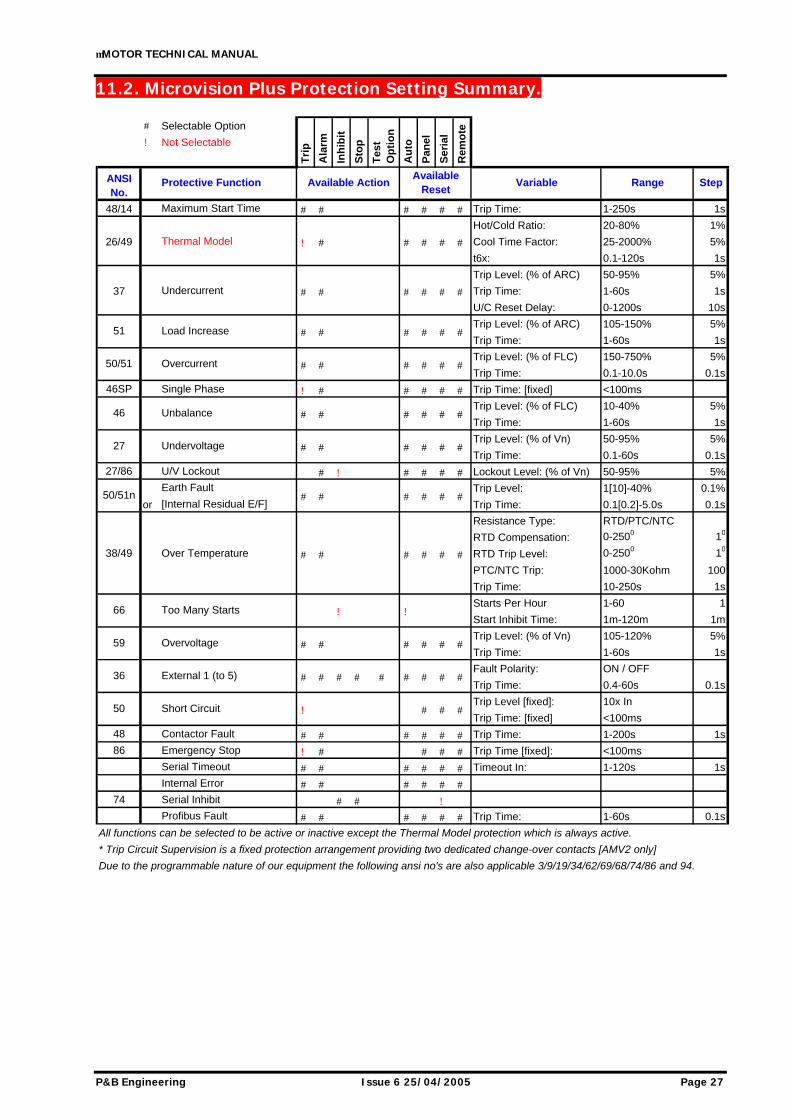
11.2. Microvision Plus Protection Setting Summary.
# Selectable Option
! Not Selectable
48/14 Maximum Start Time # # # # # # Trip Time: 1-250s 1s
Hot/Cold Ratio: 20-80% 1%
26/49 Thermal Model ! # # # # # Cool Time Factor: 25-2000% 5%
All functions can be selected to be active or inactive except the Thermal Model protection which is always active.
* Trip Circuit Supervision is a fixed protection arrangement providing two dedicated change-over contacts [AMV2 only]
Due to the programmable nature of our equipment the following ansi no's are also applicable 3/9/19/34/62/69/68/74/86 and 94.
66
Available Action
Tes
t O
pti
on
Protective Function
Inh
ibit
Sto
p
Tri
p
Ala
rm
50/51
Au
to
Available Reset
Pan
el
Ser
ial
Rem
ote
Variable Range Step
51 # # # #
ANSI No.
46
27
50/51n
Undervoltage
Unbalance
Overcurrent
Load Increase # #
##
# #
####
# #
# # # # # #
# #
# # # # # #
59 Overvoltage # # # # # #
Short Circuit50
36 # #
! # # #
# # # ##
Too Many Starts ! !
#External 1 (to 5) #
µMOTOR TECHNICAL MANUAL
Page 28 Issue 6 25/04/2005 P&B Engineering
12. Serial Settings. Serial Enabled / Disabled. This setting allows the user to enable the Microvision Plus serial communications port. This setting must be set to ‘Enable’ if communication with the relay through any serial link is required. Drive Number. This setting range 1 to 32 (125 Profibus), with a default setting of 1, identifies the Microvision Plus unit to the Xcell unit (or any Master device connected to the Data highway) to which the RS485 or Profibus port is connected. When updating firmware the auto program mode requires the drive number to be 1. RS485 Baud Rate. This setting allows the user to configure the appropriate communications baud rate such that the Microvision Plus can communicate effectively on the Data Highway to which it is connected. RS232 Baud Rate. This setting allows the user to configure the baud rate for the front mounted RS232 port. Serial Delay. The Microvision Plus may be configured to respond to a request for information from the serial port instantly or after a designated delay. A communications delay may be beneficial to ensure the Master device on the Data Highway receives all information sent back by the Microvision Plus without enduring data collisions on the network. Fast Scan Words. A Fast Scan is a system used when operating in conjunction with the XCell Data Concentrator. As the XCell polls relays attached on its network, the fastscan settings allows the user to select important data to be read back faster. The data on the communications link is broken into Fast Scan Data (or Process Critical Data) and Slow Scan or Full Read Data (Electrical Engineering Data). The amount of Fast Scan Data to be sent back to the XCell in response to a request is configurable. This setting has the range 4, 6 or 8 Words. A setting of 4 Words will give 3 Fast Scans. The remaining Word is taken up by the Thermal Capacity. A setting of 6 Words will give 5 configurable Fast Scans and a setting of 8 Words will allow 7 configurable Fast Scans. The configuration of Fast Scan is not necessary unless the Microvision Plus in used in conjunction with the XCell unit. Fast Scan 1 to 7. Each FastScan number can be programmed to export important data when requested. This number references an internal address in Microvision Plus and allows configurable data mapping between units. Typical data could be Average Phase Current, Motor Load and so on. A table of the FastScan reference numbers can be found in Appendix 6.
µMOTOR TECHNICAL MANUAL
P&B Engineering Issue 6 25/04/2005 Page 29
Max Scan Time. This setting need only be used in order to limit the amount of data traffic on a RS485 network. Dynamic data can change rapidly, this setting allows the Microvision Plus to limit the number of updates it makes to its Fast Scan values. Protocol. The RS485 serial communications port may be configured to operate using a slave implementation of Modbus RTU® or P&B Engineering’s own protocol “P&B Standard” designed to remove some of the speed issues associated with a function based protocol like Modbus. Parity. This setting allows the user to set the parity to match that of the host system on the serial link. The options are “Odd”, “Even” and “None”. Not required if Profibus. Serial Timeout Protection. This setting is a protective function and is described in detail in section 16.1.1. Serial Inhibit. This setting is a protective function and is described in detail in section 16.1.2. Profibus DP Fault. This setting is a protective function and is described in detail in sections 12.1 and 16.1.21.
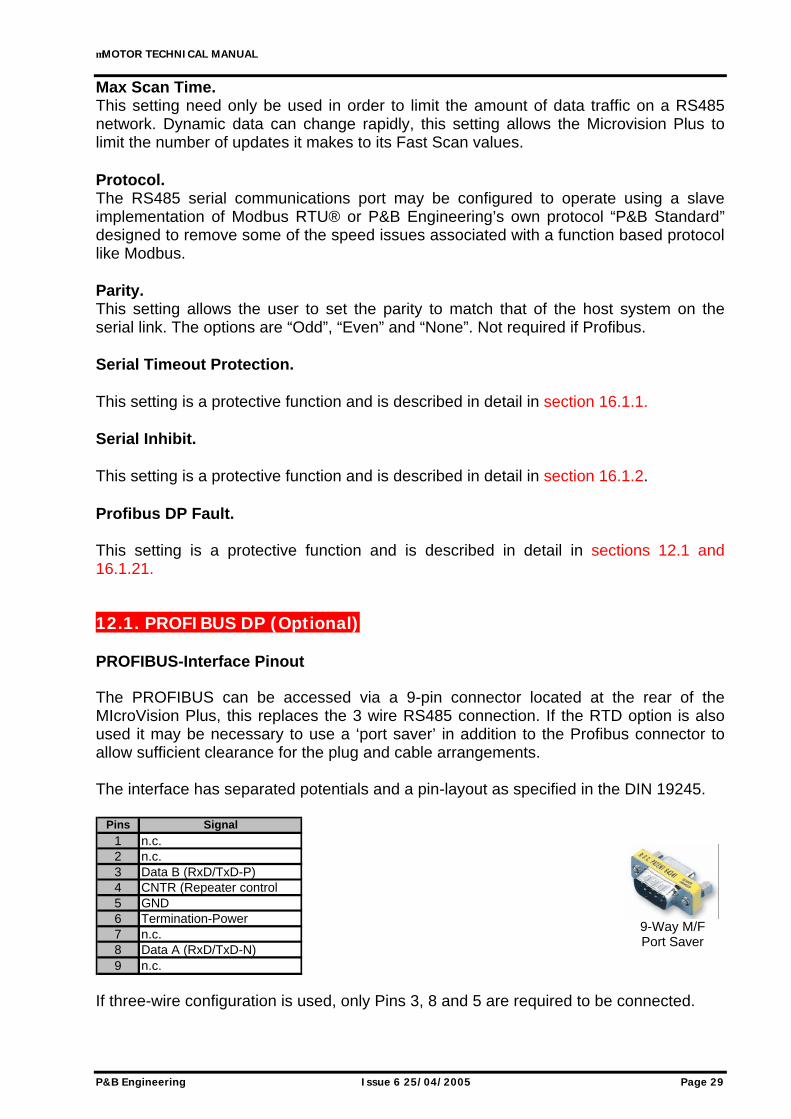
12.1. PROFIBUS DP (Optional) PROFIBUS-Interface Pinout The PROFIBUS can be accessed via a 9-pin connector located at the rear of the MIcroVision Plus, this replaces the 3 wire RS485 connection. If the RTD option is also used it may be necessary to use a ‘port saver’ in addition to the Profibus connector to allow sufficient clearance for the plug and cable arrangements. The interface has separated potentials and a pin-layout as specified in the DIN 19245.
Pins Signal1 n.c.2 n.c.3 Data B (RxD/TxD-P)4 CNTR (Repeater control 5 GND6 Termination-Power7 n.c.8 Data A (RxD/TxD-N)9 n.c.
If three-wire configuration is used, only Pins 3, 8 and 5 are required to be connected.
9-Way M/F Port Saver
µMOTOR TECHNICAL MANUAL
Page 30 Issue 6 25/04/2005 P&B Engineering
PROFIBUS Cable The PROFIBUS standard DIN 19245 Part1 and Part3 permits two types of bus cable (Cable A and Cable B). PROFIBUS Cable Parameter
Cable A Cable B
PROFIBUS-DP DIN19245 Part 1 / DIN 19245 Part 3 Chap. 6.2 4.91 Chap. 3.1.2.3
The maximum bus length depends on the type of cable and the baud rate (see table). Maximum Bus Length
Baud rate KBit/s 9,6 19,2 93,75 187.5 500 1500
Cable A, max. distance in m
(without repeater)
Cable B, max. distance in m
(without repeater)200 -
1200 1200
1200 1200 1200 600
1200 1000 400 200
The maximum bus length can be extended until approx. 10 km with repeaters. The max. number of repeaters that can be used in a network depends on the type of the repeater and is between 3 and 10. Main features of the MVP Profibus link
• Supports the following baud rates: -
9.6Kbps 19.2Kbps
93.75Kbps 187.5Kbps
500Kbps 1.5Mbps
NOTE: Recognition of data transfer rate is automatic.
• When VPC3+ carries out a DP communication, internally within the relay it automatically sets up all standard DP-SAPs. The following SAPs are supported: SAP53, SAP55, SAP56, SAP57, SAP58, SAP59, SAP60, SAP61, SAP62 and Default SAP (Data exchange).
• One master can communicate with up to 125 Profibus-DP slaves with repeaters.
µMOTOR TECHNICAL MANUAL
P&B Engineering Issue 6 25/04/2005 Page 31
When using the Microvision Plus with the dedicated PROFIBUS option, the following protocols can be used, P&B Std., MODBUS RTU, P&B Inv. and P&B DP. When using all but the P&B DP option, the protocol should be implemented in accordance with the protocol specifications. However, if the P&B DP option is chosen then the communication is handled in the following way. Data is automatically configured and transmitted by the Microvision Plus to the PROFIBUS master without the need for the PROFIBUS master to send requests to the Microvision Plus, as is the case when using any of the other protocol options. The amount of data returned by the Microvision Plus is determined by the number of fastscan words chosen. Only one byte is used for the command outputs to the Microvision Plus. When using the P&B DP protocol option then one of the following should be chosen from the GSD file module list: - 8 Bytes In + 1 Byte Out (choose this option if fastscan words is set to 4) 12 Bytes In + 1 Byte Out (choose this option if fastscan words is set to 6) 16 Bytes In + 1 Byte Out (choose this option if fastscan words is set to 8) P&B DP Input Structure First Byte = MVP Logic Status Second Byte = MVP Thermal Capacity Third & Fourth Bytes = MVP FS1 Fifth & Sixth Bytes = MVP FS2 Seventh & Eighth Bytes = MVP FS3 If 6 fast scan words chosen then the additional bytes are included. Ninth & Tenth Bytes = MVP FS4 Eleventh & Twelfth Bytes = MVP FS5 If 8 fast scan words chosen then the additional bytes are included. Thirteenth & Fourteenth Bytes = MVP FS6 Fifteenth & Sixteenth Bytes = MVP FS7 P&B DP Output Command Structure START A = 80 Hex STARTB = 81 Hex STOP = 82 Hex RESET = 84 Hex SERIAL INHIBIT = C0 Hex CLEAR INHIBIT = 80 Hex + any of the other command options START B, STOP or RESET Care should be taken when using the CLEAR INHIBIT command as it is possible to both clear the inhibit and either START, STOP, or RESET the drive at the same time.
µMOTOR TECHNICAL MANUAL
Page 32 Issue 6 25/04/2005 P&B Engineering
13. Motor Settings. CT Primary. This setting allows the user to program the primary current rating of the protection class current transformers on the supply phases. It is assumed that all phase current transformers are of the same rating. There is no need to enter the current transformer secondary rating as the MVP is pre-programmed depending on whether the relay has been purchased with a 1A, 2A or 5A CT input. If the Hall Effect Sensor (HES) is used then the CT Primary should be set to the calibrated setting of the Sensor. If motors are connected using the direct connect technique then the CT Primary should be set as per the rating of the CT Secondary. On selection of the two-speed starter types the ‘CT Primary’ setting will offer two settings, ‘CT Primary (LOW)’ and ‘CT Primary (HIGH)’. This allows connection of two independent sets of current transformers to the MVP to monitor current in the fast and slow supply arms to the motor. If only one set of current transformers is used then these two values are set to the same ‘CT Primary’ value. It must be noted that although the Primary values can differ the Secondary values must be the same i.e. 1A, 2A or 5A.
The HES cannot be used in this type of dual-set CT application.
VT Primary. This setting allows the user to program the primary voltage rating of the voltage transformer (if used). VT Secondary. This setting allows the user to program the secondary voltage rating of the voltage transformer (if used). The VT Primary and Secondary should be set to the same value if directly connecting the voltage input without a step-down transformer. Full Load Current (FLC). The FLC is the motors continuous maximum Full Load Current rating as provided in the motor manufacturers data. The settable range is dependant on the ‘CT Primary’ setting. The ‘FLC’ setting enables all protective functions except Undercurrent and Load Increase to be set in terms of a percentage of FLC and enables the MVP to display the “Motor Load” in terms of a percentage a FLC. Running Current (RC). This setting allows the user to program the motors Running Current when supplying a typical load at normal speed. This value is typically less than the motor FLC rating and enables the protective functions (Under Current and Load Increased) to be set in terms of a percentage of this value.
µMOTOR TECHNICAL MANUAL
P&B Engineering Issue 6 25/04/2005 Page 33
Voltage. This should be set to the line voltage of the supply. It is necessary for power calculations and is used for the Under / Overvoltage, Undervoltage Restart and Undervoltage Lockout protection features. As an example if the voltage input was connected between two phases on a 415V system this setting would be 415V. If however the voltage input was connected between a phase and neutral then this setting should be 240V. Voltage Ref. This parameter can be set to Ph-N (Phase to Neutral) or Ph-Ph (Phase to Phase) with a reverse feature to avoid re-wiring for phase correction to match the connection type above. E/F Primary. This setting allows the user to program the primary current rating of the protection class current transformer used to measure the earth fault current. If a residual current transformer connection is used to detect earth fault then the same setting as for CT Primary should be used. If the Internal Residual Connection is used for earth fault protection then this setting is hidden. KW Sample Period. This setting range 5 to 60 min in steps of 1min determines the period over which a measurement is taken to integrate the Kilowatt Hours value.
µMOTOR TECHNICAL MANUAL
Page 34 Issue 6 25/04/2005 P&B Engineering
14. Starting Methods. The MVP relay is designed to be used as an intelligent motor starter for LV systems offering comprehensive protection and control features. A number of starting methods are catered for;
14.1. Direct On Line (DOL) Direct On Line starting is used for electrically held contactors and allows the motor to be run in one direction only. It applies the full line voltage to the windings immediately upon starting. DOL Starter expects Start A to be used a hardwired digital input control (momentary or maintained). Output Relay 1 (RUN) will close to pull in the contactor, Cont A digital input should be used if contactor feedback is required through the digital inputs or contactor fault protection is needed. Output 1 will release when stopped or tripped. Typically the inrush current of a 415V motor would be 6x FLC, hence the thermal model protection, t6x. Higher voltage systems generally have lower inrush demands.
14.2. Star / Delta 2 (S/D2) This starting technique is typically used to reduce the starting currents normally seen when starting a motor by Direct On Line. By reducing the voltage applied to the motor windings the current is also reduced, as is the starting torque. Care must be taken to ensure the motor can generate enough torque to accelerate on start-up when connected in STAR. Start A is used as the hardwired or remote start signal and closes Output Relay 1. This output is used to pull in a contactor which connects the motor in a star type connection. Cont A is used for feedback and / or contactor fault protection. The Star connection provides root 3 of the system voltage to the motor. This has the effect of limiting the inrush current to 2x (as opposed to 6x for normal 415V drives). Once this current increases and falls below 100% of FLC. Output relay 1 opens. If the current fails to fall below 100% FLC then Output relay 1 opens after the Max time in star setting. After the transition time Output Relay 2 closes to pull in a contactor connecting the motor in a delta formation. Cont B is used for feedback and / or contactor fault protection of the delta contactor. Once the delta inrush current falls below FLC the MVP will consider the motor as running. Maximum Start Time protection functions from the time at which the unit transfers to the delta starter. Output Relay 1 can be held closed for the duration of the Max Time in Star by setting Stay in Star to YES irrespective of the normal current based change-over.
µMOTOR TECHNICAL MANUAL
P&B Engineering Issue 6 25/04/2005 Page 35
14.3. Star/Delta 3 (S/D3) For Star / Delta 3 the operation is the same as for the S/D2 type with the exception that Output Relay 3 controls the LINE contactor. Once a Start A command is received both the Star and Line contacts closes, upon transition the Star opens as normal. The line contact remains closed throughout and only released when the drive is stopped or tripped. For both S/D2 and S/D3 the Start Time (statistical data) is determined solely by the time taken from the motor starting in Star formation to the transition to the DELTA connection.
14.4. Direct On Line Reversing (DOLR) With Direct On Line Reversing Output Relay 1(FORWARD) is used to control the motor in the forward direction and Output Relay 2 (REVERSE) is used to control the motor in the reverse direction. The full line voltage is applied to the motor windings immediately upon starting in either direction. Start A and Cont A are the start command and feedback for the forward direction. Start B and Cont B are associated with the reverse direction.
14.5. 2-Speed / DOW 2-Speed In 2-Speed mode Start A controls Output Relay 1(LOW) and is used to control the motor in the Low speed with Cont A used as feedback confirmation and / or protection. Start B controls Output Relay 2(HIGH) and is used to control the motor in the high speed with Cont B used as feedback confirmation and / or protection. This type of starter is used on 2-Speed motors which typically have 2 sets of windings. Different sets of CT’s can be used if the windings are considerably different for one another. Example. The high speed winding is rated at 90 Amps, therefore 100/1A 5p10 2.5VA CT’s are used. If the low speed winding is rated at anything less than 50% of the CT Primary (100A) then a second set of CT’s would be required. In DOW (Direct on Windings) mode the drive can be started in either speed, once in the running mode the motor can be switched to the other speed without stopping. In normal 2-Speed mode the motor must be stopped before transferring to the other speed. This transfer between speeds can be partly automated in order to avoid the need to press stop before changing motor speeds. Example. Low to High = Enabled, Low to High Transfer = 5seconds. If running in High speed in order switch to low speed the drive must be stopped using a Stop serial command, a Stop digital input or a Stop panel key press. The drive must then receive a Start A command to run in low speed. In this example the drive can be started in low speed with Start A, if Start B is pressed the drive stops waits 5 seconds then automatically starts in high speed. If configured to restart the last running speed before power loss would be used to restart the motor.
µMOTOR TECHNICAL MANUAL
Page 36 Issue 6 25/04/2005 P&B Engineering
14.6. Air Circuit Breaker (ACB) This starter type must be selected when the motor is controlled by a circuit breaker or mechanically held contactor rather than an electrical held contactor regardless if the motor is in actual fact a DOL starter. Start A drives Output Relay 1(CLOSE) to close the circuit breaker and start the motor and Output Relay 2(OPEN) is used to open the circuit breaker and stop the motor. The operation of the CLOSE and OPEN relays is momentary (pulse type) and has a programmable duration. A Digital Input can be programmed to provide Circuit Breaker status feedback, Cont A is renamed as ACB Feedback in ACB mode.
14.7. Direct On Line with Heater (DOLH) This method of starting a motor is for applications where humidity / condensation causes problems in motor windings. Direct on Line with Heater “DOLH” avoids starting a motor when the windings may be damp by energising Output Relay 2 (HEATER) whilst the motor is stopped. In typically situations this output relay would control a contactor feeding a heater embedded in the windings whilst the motor is stopped to evaporate any condensation which may otherwise have developed in the motor. This starter type is similar to Direct on Line “DOL” where Start A is used to drive Output Relay 1(RUN) to control the motor in one direction only. Output Relay 2(Heater) is used to control the Heater embedded in the windings or inject a current in the windings whilst the motor is stopped. Output Relay 2 will automatically energise after 1 hour when the motor is stopped and de-energise when the drive is started.
14.8. Direct On Line Reversing Heater (DOLRH) This method of starting is the same as that above, but it is used with bi-directional motors. Start A drives Output Relay 1(Forward) to control the motor in the forward direction and Start B drives Output Relay 2(Reverse) to control the motor in the reverse direction. Output Relay 3(Heater) follows the same function as with DOLH.
14.9. Variable Speed Drive (VSD) Variable Speed Drives allow precise control of the motor speed by varying the frequency or applied voltage to a motor. By the very nature of variable speed drives the initial large “inrush” current typically seen on Direct On Line started motors can be avoided. For all other starter types (except VSD) the MVP requires the completion of a successful starting sequence (i.e. the current must exceed 105%FLC and return to or below 100% FLC before the motor is considered as running). This starter type allows the MVP to consider the motor as running immediately after a start signal has been issued. Start A drives Output Relay 1(RUN) to control the motor (which is assumed to be fed from an electrically held contactor). The VSD starter type should also be selected for other starters which do not exhibit inrush characteristics, such as soft starters. For all Starter Types except VSD the successful completion of a starting sequence is required before the motor will be considered running and protection features are enabled. It is recommended the CT’s fed into MVP are primary to the VSD inverter.
µMOTOR TECHNICAL MANUAL
P&B Engineering Issue 6 25/04/2005 Page 37
15. Starter Settings. Starting Method. The Starting method or starter type determines how the connected drive is to be controlled. Whether via a single contactor, a two coil operated breaker etc. Each Starter type is explained in full in section 14. On selection of some starter types other parameter are also required to achieve correct operation. See section 15.1. For example when Star/Delta 2 is selected, values for the transition time behaviour between star and delta closing is required. Start A/B. This setting, (“Momentary” or “Maintained”) determines the type of digital input signal used to start and run a motor. A momentary input (such as a push button switch) starts the motor when the button is pushed. The motor will remain running after the push button is released. If the motor is started by a momentary switch select “Momentary” in the Start A/B “pop up option screen”. A maintained input starts the motor when the switch changes state from open to closed. The change of state from closed to open stops the motor. If the motor is started by a maintained signal select “Maintained” in the Start A/B option. The motor can be stopped by using the Stop digital input in either Maintained or Momentary modes. In some applications there may be two inputs for running motor control, i.e. one for forward direction and another for reverse (or one for slow and another for high speed). In such applications two switches may be wired to the digital inputs for control of relay A and relay B respectively. The Start A/B setting applies to both switches. They cannot be configured independently. Undervoltage Restart. This setting activates the undervoltage restart (sometimes referred to as auto re-acceleration) function. A motor must be considered as running prior to voltage or auxiliary supply loss in order for a restart to take effect. This function restarts the motor after a voltage or auxiliary supply loss. If the voltage or supply loss is less than 200mS the motor will carry on running. If the power to the motor is lost for less than the Restart Time, on voltage restoration, the relay will restart the motor after the Restart Delay has elapsed providing no inhibit exists (e.g. UV lockout protection). If the power loss is greater than the Restart Time the relay will not restart the motor. Once this is enabled it allows the user to set the Undervoltage Restart Time and the Undervoltage Restart Delay. If the thermal capacity of the running motor is 50% or more, in some cases the motor will be prevented from restarting after a power loss by an active thermal inhibit as there would be insufficient remaining Thermal Capacity to allow the motor to run up. In some applications it may be desirable to inhibit a restart of a motor for process reasons even though the conditions exist which would ordinarily result in an automated restart taking place. In this case a digital input can be used to either block or allow this restart. See section 6.11.
µMOTOR TECHNICAL MANUAL
Page 38 Issue 6 25/04/2005 P&B Engineering
Undervoltage Restart Time. This setting determines the allowable off time (the time a relay can be powered off or without nominal voltage) such that if the power is restored or the voltage returns to normal within this time a restart can occur. Voltage loss could be result of upstream supplies changing over, an HV motor starting or some other condition which causes downstream connected drives to either trip on undervoltage protection or cause contactors to drop out. Undervoltage Restart Delay. Once power has returned the restart delay can be used to help control the sequence of a process restart after an outage. This is a settable time to hold off automated start control after voltage restoration. This can be used to prevent an entire bus system of motor starters from trying to reaccelerate at the same time. Restart Sense. This setting, which can be set to ‘Supply’ or ‘Supply or Reference’, determines the signal that is examined after a power loss to determine whether an Undervoltage Restart will occur. If it is set to ‘Supply’ then after a power loss and when the supply to the relay is active again a restart will occur. If it is set to ‘Supply or Reference’ the relay will examine if there is voltage on the Bus-bars that supply the motor. Specifically, if the voltage dips below 65% of the line voltage then a Stop is called, if the voltage is restored to above 65% of the line voltage (within the set Restart Time) then the MVP will orchestrate the restart. This setting is for the case where the relay is powered off an Auxiliary supply and not from the supplying Bus-bars. Start and Stop Setup Source. This setting is used to determine the allowable source control for the Start and Stop signals to the motor. The Start and Stop signals can come from three different type of input:- Panel - the buttons on the front of the relay. Remote - from the digital inputs to the relay. Serial - through the serial link on the relay. The user can configure which source an allowable start or stop command signal can come from using the logic line
See section 9.3.4.1 for a full explanation.
100010001110001Sav NxtL/A Pan
µMOTOR TECHNICAL MANUAL
P&B Engineering Issue 6 25/04/2005 Page 39
15.1. Additional Starter Settings. The following settings are only configurable when specific starter types are selected. # 2-Speed Starter (not DOW) ! Star / Delta Starters % DOL with Reverse Starters " ACB Starter #Low to High Transfer In order to achieve dual speed control it is necessary to use both Start A and Start B when using hardwired digital inputs. This setting is the motor stopped time when switching between Low speed to High speed using only the Start A and Start B inputs i.e no issued Stop command. An explanation is given in section 14.5. #High to Low Transfer As above, for the application of High to Low speed transfer. #Low to High This setting allows the Low to High Transfer time to be used. If this is set to disabled then speed transfer can only be carried out if the motor is stopped after a Start A command prior to issuing a Start B command #High to Low As above, for the application of High to Low speed transfer. !Transition Time. This setting determines the time period between a change-over from de-energising the Star output to energising the Delta output. !Max Time in Star. This setting, determines the maximum time that the relay can hold the Star output closed. !Stay in Star If the inrush current falls below 100% of FLC the transition to delta would normally take place. If enabled this setting holds the star output closed for the duration of the Max Time in Star setting %Transfer Lock. Operates an inhibit period between switching from the forward to reverse direction or vice-versa. An attached load may continue to rotate after the supply power is removed, energising in the reverse direction against this momentum could cause serious mechanical damage to a motor. %Transfer Time. This is the settable inhibit time when the transfer lock is used. "ACB Pulse Time. The Close and Open output relays are closed only for the set ACB Pulse time.
µMOTOR TECHNICAL MANUAL
Page 40 Issue 6 25/04/2005 P&B Engineering
16. Protection Settings. Each protection function is configurable independently of the others. The available action, the type of reset, the various threshold levels and trip timers for each and every protection function can be found in section 11.2. This section describes in detail what each function does and how it operates. Function. If a particular protective function is required for use it should be selected and set to Function: Enabled. That function now operates as per its configuration. On exit the protective list will show to the left hand side of the name a tick if the function is enabled, and A or T, or both if set, which operate an Alarm or a Trip. If a particular function is not required it can be left disabled and it will display DISABLED underneath the function name.
Alarm. An Alarm is considered as a high level function. If enabled, an A will appear alongside the protection setting description. If the function activates it will be recorded as part of the alarm history and cause MVP to enter an alarm state; the fault will be displayed in the active faults page and the right hand LED will turn orange. If an output relay is set as Alarm it will change state with the fault.
Trip. A Trip is considered as a high level function. If enabled, a T will appear alongside the protection setting description. If the function activates it will be recorded as part of the trip history and cause MVP to enter a trip state; the fault will be displayed in the active faults page and the unit will automatically display that page, the right hand LED will turn RED. If an output relay is set as Trip it will change state with the fault. Even if no output relay is set as Trip the MVP will stop the drive by releasing the RUN output (or pulsing the OPEN output).
Inhibit. An Inhibit is considered as a high level function. If enabled and the function activates it will display in the active faults page with a letter I to indicate the function is causing an inhibit. The drive may continue to run but cannot be restarted whilst the inhibit remains. The left hand LED will turn orange. The Stop open condition will also cause an inhibit preventing the drive from starting unless; the input is closed or the drive is entered into a state whereby the remote stop source can be ignored. It is generally good practice to wire the stop signal through the contactor preventing it from closing whilst the stop is open unless the isolator or main power connector is out of service.
Note: this function is only available for external fault protection settings.
µMOTOR TECHNICAL MANUAL
P&B Engineering Issue 6 25/04/2005 Page 41
Reset. The configuration of the reset allows that particular function to be cleared or reset to a healthy condition providing the condition that caused the fault, alarm or inhibit has been removed. If a fault remains active an asterix (∗) appears with the T,A or I and fault description in the active faults page.
Auto Reset. This option, when enabled, automatically resets the Fault when the situation that caused the trip has been removed. If Auto Reset is selected the other reset options are unavailable.
Panel-Reset. This option, when Enabled, allows a reset of a fault to be carried out from the front panel of the relay. A reset button will be displayed in the active fault page if any fault has been removed and is enabled for a panel reset.
Serial-Reset. This option, when Enabled, allows a reset of a fault to be carried out through the serial link of the relay.
Remote-Reset. This option, when Enabled, allows a reset of a fault to be carried out through the digital inputs to the relay. A digital input must be set to Reset Faults and must be closed after the fault condition has been removed in order for the reset to operate.
µMOTOR TECHNICAL MANUAL
Page 42 Issue 6 25/04/2005 P&B Engineering
16.1. Protection Functions. 16.1.1. Serial Timeout. For a set period of inactivity on the rear communication port the unit can be configured to take some action in the event. It is worth noting that the MVP device is slave to any host system, the unit will not send information via the serial port unless it has been requested by a master device. 16.1.2. Serial Inhibit. The serial inhibit protection function inhibits a motor from starting, stop a motor running or can be configured to stop a motor and inhibit further starting as a result of a serial command. This inhibit will be registered by the MVP as an active fault condition. This protection feature allows remote stations (control rooms) to inhibit motor starts via the communications port to lockout and prevent local control of the motor. The Serial Inhibit protection feature may only be disabled by writing to the correct register using the serial port. i.e. The inhibit function may not be disabled via remote switches or from the front panel. The Serial Inhibit register address may be found in both the Modbus and P&B Network Gold Communications Memory Map Document. 16.1.3. Maximum Start Time. When starting a motor a starting sequence must be completed before the MVP will register the motor as “Running”. For this sequence to be complete the starting current must exceed 105% of the programmed motor full load current (FLC) then fall to or below 100% FLC. The Maximum Start Time protection feature may be configured to allow a maximum time for the motor to complete the starting sequence. If the motor has not been registered as “Running” before the expiry of the programmed timer then the unit may be configured to trip, alarm or indicate as a result. If the VSD starter type is used this function is not required.
Trip Time. This setting determines the maximum time that the motor is allowed to take to complete it's starting sequence. The starting sequence ends when the current falls to under 100% of FLC at which point the message "Running" appears on the screen. 16.1.4. Thermal Model. The Thermal Model protection is arguably the most fundamental feature any motor protective relay. This is implemented as a software model of the electromechanical overload operation of the heating element and bimetallic coil which became the method of protecting electrical plant.
The Thermal Model protection cannot be switched off, that means even with incorrect settings the relay would try and offer some protection in an overloaded condition.
µMOTOR TECHNICAL MANUAL
P&B Engineering Issue 6 25/04/2005 Page 43
In order for this protection to operate successfully a motor is assumed to have a “thermal capacity” or TC. In its simplest terms, a motor start from standstill using a DOL method will absorb 6x its full load current (FLC) in order to magnetise and establish a magnetic field. Once the Motor overcomes its initial inertia and begins to rotate, the inrush current decreases until the motor reaches its nominal rotating speed and draws a continuous current, FLC. Once the TC reaches 100% a trip occurs. From standstill, with a thermal capacity of zero (referred to as the Cold Condition) a motor has 100% of its TC available to start. If the inrush of 6X FLC remained steady (stalled rotor) the time taken to absorb 100% TC and a trip would be equal to the t6x setting. This is called the basic thermal characteristic. The graph, right, shows multiples of FLC against the operating time. The Thermal model curve remains DT above 6x to allow for fuse discrimination. Assuming t6x = 1: If a 2x inrush, from cold (0%) occurred the resultant trip time would be 10s. If the Pre-Alarm setting is Enabled an Alarm is called when the Thermal Capacity reaches 95%. When it reaches 100% a Trip is called. The Pre-Alarm can be disabled, where as the Trip cannot. When a motor successfully starts and maintains normal a FLC its TC increases to a steady state condition which is determined by the Hot / Cold ratio (H/C). If an overload occurred from this steady state condition the trip time is faster as the motor has already absorbed some thermal capacity up to its steady state (referred to as the Hot Condition). How much it has absorbed is dependant upon the withstand times of the motor or, its H/C ratio.
Hot/Cold Ratio. The H/C ratio is calculated from the motor manufacturers’ data, overload times are quoted both from a stand still (cold) overload and for a running (hot) overload. The Hot withstand time divided by the Cold withstand time gives us a ratio. This ratio, expressed as a percentage, then equates to a steady state running condition. i.e.
% Hot / Cold Ratio Setting 80 70 60 50 40 30 20 Steady State % Thermal capacity Running At 100% FLC
17 26 35 44 52 61 69
Available % Thermal Capacity For Overloads
83 74 65 56 48 39 31
µMOTOR TECHNICAL MANUAL
Page 44 Issue 6 25/04/2005 P&B Engineering
If we take a ratio of 60%. After a start and after running at FLC we reach the steady state thermal capacity of 35%, we have 65% available before a trip occurs, if an overload did occur the trip time is determined by the multiple of the overload condition (2x, 3x FLC etc) and the t6x setting. The overload level for MVP has a fixed pick-up of 1.05% of FLC, therefore the current must be in excess of this value for the thermal capacity to increase towards 100%. During the start and run-up of a motor the absorbed TC is generally more than the steady state TC, so it does not follow that with a H/C ratio of 50% and 44% running TC that a second start would be permitted. A second start could only take place once sufficient TC is available. The unit may enter an inhibit mode to prevent a start. The stats page under the Data menu indicates the TC absorbed during the last start. Thermal memory is retained in non volatile memory to avoid resetting on a power down.
Cool Time Factor. The time taken for TC to decrease is usually longer than the heating constant as motors generally dissipate absorbed TC by radiation. The Cool Time Factor should be set according to the ratio of the motor cooling time constant at standstill divided by the heating time constant when running at normal speed. The higher the value of this setting the longer it will take for the thermal capacity to reduce to the level required to enable a restart.
t6x.
This setting defines the basic thermal characteristic, the trip time for a 6x FLC overload condition from 0% absorbed TC. In real terms, the trip time for a continuous 6x overload from 0% to 100% will equate directly to the t6x setting. (i.e. if t6x is set at 10, the trip time will be 10 seconds) The formulas below describe how the thermal model operates from cold and hot. Cold Condition
where; ‘p’ is the multiple of FLC ‘a’ is the t6x setting ‘tc’ is the operating time (in seconds)
Running (Hot) Condition
‘IL’ is the steady state prior to overload (If motor is running at FLC IL = 1) ‘H/C’ is the hot cold ratio expressed as a decimal i.e. 40% = 0.40
A trip time table for overload level with respect to the H/C condition is given in Appendix 5. An application example showing how the Thermal Model settings are calculated is available on our website: www.pbeng.co.uk In 2-speed motor applications two t6x times are to be set, one for low speed and the other for high speed.
−= 20512
2log32
.pp
e.a.ct
( )
−
−−
= 22
22
05.1
1log..32
p
ICH
pa
L
ect
µMOTOR TECHNICAL MANUAL
P&B Engineering Issue 6 25/04/2005 Page 45
16.1.5. Too Many Starts. The MVP will inhibit and can be configured to indicate as a result of too many starts occurring. It is often desirable to prevent multiple starts of a drive particularly if it is the cause of stability problems on the power system. No reset type is available. The inhibit will auto-reset after the selected time delay has elapsed. A start can then be made.
Starts per Period. The number of allowable starts before actively inhibiting further starts from being made.
Start Inhibit Time. The start inhibit time can be set as a fixed time for the inhibit to be active.
Start Period. The Start period can be set from 1 minute to 60 minutes.
Start Inhibit Type. This setting selects the time length for the inhibit, there are three options.
1) Inhibit Time (start inhibit time setting) 2) Remaining SP (the remaining start period) 3) SP + IT (the remaining start period + the fixed Inhibit Time)
Example 1. A Motor can be started a maximum of 4 times in one hour. We can further say those starts must be evenly spaced throughout the hour. The Start Period should be set to 15mins with a Starts per Period of 1. The Start Inhibit Type should be set to Remaining SP. If the drive starts and runs for 10 minutes and is then stopped, the inhibit will last for 5 minutes. (Start Period = 15mins) – (run time = 10mins) = (Remaining SP = 5mins) If the drives starts once and runs for 15mins a second start can be made immediately. Example 2. A Motor can be started three successive times within 20mins, if three starts are made the drive should be inhibited for a period of 30 minutes. The Start Period should be set to 20mins with a Start per Period of 3. The Start inhibit Type should be set to Inhibit Time with a Start Inhibit Time setting of 30mins. If the drive starts and stops three times within 20mins the fourth start can only take place after the 30mins from the last stop. If the drive starts twice and continues to run as long as the total time for the two starts is in excess of 20mins, the drive can be restarted again immediately.
µMOTOR TECHNICAL MANUAL
Page 46 Issue 6 25/04/2005 P&B Engineering
16.1.6. Contactor Fault. Contactor Fault protection is determined from the digital input status of Cont A and Cont B inputs to confirm run/close, stop/open and trip commands (ACB Feedback when in ACB starter type). If the feedback fails to confirm a sent signal via the output relays the configured action for this function will take place. Regardless whether Start A/B is set to momentary or maintained, feedback signals are always maintained signals.
Trip Time. Determines the allowable propagation time of a feedback signal before any action is taken. 16.1.7. Emergency Stop. In many applications an Emergency Stop pushbutton is wired directly in line with the contactor energising coil to stop the motor immediately when pressed. Auxiliary contacts on the Emergency Stop pushbutton may be wired to a digital input to notify the relay that an emergency stop has been triggered. The unit will always issue an instantaneous trip if it receives an E. Stop signal. A digital input must be assigned as ‘E. Stop’ in order for this function operate correctly. The Emergency Stop feature is always fail-safe, meaning it should be continuously closed to denote a healthy signal. An Emergency Stop trip is only disabled by the Short Circuit protection function when the fault current is in excess of 10xIn. 16.1.8. Undercurrent. The MVP may be configured to trip, alarm and/or indicate as a result of an undercurrent condition, usually the result of loss of load. Undercurrent protection is disabled during STARTING and in TEST MODE.
Trip Level. The undercurrent pickup is set as a percentage of the Actual Running Current (ARC) which is the typical loaded current of the motor. The undercurrent pickup should be set higher than the unloaded current the motor may be subject to. If the measured current falls below this threshold level the unit will action after the time delay.
Trip Time. The trip time is set to determine how long an undercurrent condition can persist before the configured action is taken.
U/C Reset Delay. When an undercurrent condition occurs the unit can be prevented from resetting until the U/C Reset Delay timer has expired. In some applications, typically well pumps the motor is cooled by the pumped fluid so the motor may be “hot” on tripping. This delay allows for a cooling period before an attempt at restart.
µMOTOR TECHNICAL MANUAL
P&B Engineering Issue 6 25/04/2005 Page 47
16.1.9. Overcurrent. The MVP may be configured to trip, alarm and/or indicate as a result of an overcurrent condition, typically caused by a phase or earth fault, mechanical jam or other heavily loaded motor condition. Overcurrent protection is usually used to ensure faults are cleared more quickly than that provided by the Thermal overload protection. Overcurrent protection is disabled during STARTING and when in TEST MODE.
Trip Level. The overcurrent pickup is set as a percentage of the Full Load Current (FLC). If the current rises and remains above the threshold level action is taken after the trip time has elapsed.
Trip Time. The trip time is set to determine how long an overcurrent condition can persist before the configured action is taken. 16.1.10. Earth Fault. The MVP may be configured to trip, alarm and/or indicate as a result of an overcurrent condition. Earth Fault measurement can be achieved in one of three ways.
a) using a core balance transformer (CBCT) b) using a residual connection from the three phase CT’s,
or, at request. c) using an internal residual connection calculated from the measured phases.
Generally it is desired that earth fault protection be instantaneous although in some applications transient earth fault currents may be seen, and requires a small delay to be imposed to prevent nuisance tripping. In most cases the earth fault protection feature should be set to ensure appropriate coordination with other devices. Depending on the type of system grounding (resistive or solidly earthed) an earth fault current has the potential to be very large. The user must be aware of the maximum earth fault current the system can experience when using the Earth Fault protection feature with a fused contactor. If solidly earthed, the earth fault current may be much higher than the rated current breaking capability of the contactor. An attempt to break a fault current in excess of its rating may cause damage to the equipment. In such applications the user should ensure appropriate coordination between the device and HRC fuses and/or disable the Short Circuit protection feature. Circuit breakers are typically rated to break the full fault current.
Trip Level. The earth fault pickup is set as a percentage of the EF CT Primary. If the current rises and remains above the threshold level action is taken after the trip time has elapsed.
With a residual connection as in ‘a’ the EF CT Primary should be set to the same value as the CT Primary. With a CBCT connection the EF CT Primary should be set to the primary rating of the CT. In an internal earth fault connection the EF CT Primary settable option is removed and the CT rating is used.
µMOTOR TECHNICAL MANUAL
Page 48 Issue 6 25/04/2005 P&B Engineering
Trip Time. The trip time is set to determine how long an earth fault condition can persist before the configured action is taken. 16.1.11. Load Increase. The MVP may be configured to trip, alarm and/or indicate as a result of a load (current based measurement) increase condition, often used to indicate process conditions such as stock on a conveyor belt. Load Increase protection is disabled during STARTING.
Trip Level. The load increase pickup is set as a percentage of the Actual Running Current (ARC). Depending on the application a load increase may be a frequent occurrence and care must be taken to prevent nuisance tripping.
Trip Time. The trip time is set to determine how long an increased load condition can persist before the configured action is taken. 16.1.12. Single Phase. The MVP may be configured to trip and/or alarm as a result of a single phasing condition, i.e. loss of one current phase, and will operate in 100ms. The function operates at 100% unbalance. If this function is disabled the unbalance protection will not operate at the 100% condition. 16.1.13. Unbalance Current. Unbalance of a three-phase motor can cause the windings to overheat as the motor continues to rotate and develop the required torque to meet the demand. Unbalance is determined thorough measured current. The amount of unbalance is calculated using one of the equations detailed below: i) If the Highest_Phase_I > 80% motor full load current (FLC):
100__
)____(% ×
−=
IPhaseHighestIPhaseLowestIPhaseHighest
Unbalance
ii) If the Highest_Phase_I < 80% of FLC:
100___
)____(% ×
−=
currentloadFullMotorIPhaseLowestIPhaseHighest
Unbalance
Trip Level.
If the unbalance increases and remains above the set level action is taken after the trip time has elapsed.
Trip Time. The trip time is set to determine how long an unbalance condition can persist before the configured action is taken.
µMOTOR TECHNICAL MANUAL
P&B Engineering Issue 6 25/04/2005 Page 49
16.1.14. Short Circuit. The Short Circuit protection feature provides the user with added protection against attempting to break fault currents in excess of the switchgears rating. This feature is typically enabled when the motor is being controlled by a circuit breaker rather than a fused contactor arrangement. It provides a fixed instantaneous trip (<100ms) at a fixed phase current setting of 10x In (where In is the phase current transformer primary setting). When this setting is disabled a trip inhibit is active for currents over 10xIn. Above 10xIn only the Thermal Model is active and the relay will trip according to the Overload Curve irrespective of other settings. This prevents a contactor from being damaged by attempting to break a fault current in excess of its rating. The intension is to allow the HRC fuse or other fault current rated device to clear the fault. 16.1.15. Undervoltage. The MVP may be configured to trip, alarm and/or indicate as a result of an undervoltage condition. Undervoltage may be due to upstream supplies changing over or HV motor starts creating downstream voltage dips. As such, undervoltage protection should be set with the ability to ride-out some undervoltage conditions to avoid unnecessary tripping. Undervoltage protection is disabled during STARTING and when in TEST MODE.
Trip Level. The undervoltage pickup is set as a percentage of the Voltage setting. If this decreases and remains below the threshold level action is taken after the trip time has elapsed.
Trip Time. The trip time is set to determine how long an undervoltage condition can persist before the configured action is taken. 16.1.16. U/V Lockout. The undervoltage lockout protection can be used as to prevent restarting of a motor after a severe voltage collapse. It can be configured as a second-stage undervoltage feature, the protection will always result in an inhibit with a selectable alarm. It operates instantaneously once the voltage falls below the set level. U/V Lockout is disabled during STARTING and when in TEST MODE.
This function should be set disabled if U/V restart is enabled as it will inhibit any auto-re-acceleration (auto-restart) from taking place after a voltage dip. Even with auto reset enabled the U/V restart will be inhibited
Trip Level.
The Undervoltage Lockout pickup level is set as a percentage of the Voltage setting and determines the level of voltage below which the motor will be inhibited from starting. 16.1.17. Overvoltage. The MVP may be configured to trip, alarm and/or indicate as a result of an overvoltage condition. Overvoltage protection is disabled during STARTING and when in TEST MODE.
µMOTOR TECHNICAL MANUAL
Page 50 Issue 6 25/04/2005 P&B Engineering
Trip Level. The overvoltage pickup is set as a percentage of the Voltage setting. If this increases and remains above the threshold level action is taken after the trip time has elapsed.
Trip Time. The trip time is set to determine how long an overvoltage condition can persist before the configured action is taken. 16.1.18. External 1 to 5. The external faults are digital input based, configurable action inputs. Up to 5 are available and bring a flexible PLC approach to the normal protective functionality. Each is independently configurable and can be used to provide permissive interlocking or process commands in addition to the normal Start and Stop functions. Each External fault can be renamed to an eleven character user defined text string, Unit Settings > Edit Custom Strings.
Function. The function can be set to any combination of Alarm, Trip, Inhibit or Stop. The function can also be set to Test option which allows the function to be active when in the test mode. Reset. Normal reset options apply, Auto or a combination of Panel, Serial and Remote.
Polarity. This option determines the polarity of the digital input that activates this function. 'OFF=Fault' (typically fed from a NC contact), means that when the digital input is Open the External Fault will action. 'ON=Fault' (typically fed from a NO contact), means that when the digital input is Closed the External Fault will action.
Trip Time. Determines the time an external input can remain in its fault state before any action is taken. 16.1.19. Over Temperature. (optional) The MVP may be configured to trip, alarm and/or indicate as a result of an over temperature condition, as seen by an external temperature probe. It can provide protection or indication of excessive heating as a result of a lack of ventilation/cooling, negative sequence currents, overvoltage and other conditions which may not be detected by the Thermal Model. The single temperature input provides allow the connection of several different types of temperature probes including: • RTD (Resistance Temperature Device – type PT100) displayed in degrees C. • PTC (Positive Temperature Coefficient Thermistor) displayed as resistance. • NTC (Negative temperature Coefficient Thermistor) displayed as resistance. When the Over Temperature function is enabled the device will also indicate as a result of a Short or Open circuited temperature probe
Resistance Type This setting determines the type connected probe, RTD, PTC or NTC.
µMOTOR TECHNICAL MANUAL
P&B Engineering Issue 6 25/04/2005 Page 51
RTD Compensation The setting allows the measured level to be manually offset.
Thermistor Trip Level. With a PTC the relay will action when the resistance exceeds the set level and with a NTC the unit will action if the resistance value changes below the set level.
RTD Trip Level. This setting determines the temperature level at which the configured action should be taken.
Trip Time. This setting determines the delay between the unit registering and maintaining a threshold pick-up and the resulting configured action. 16.1.20. Internal Error. The MVP incorporates an internal software and hardware watchdog feature to monitor the integrity of both on board hardware and software systems. This feature may be configured to indicate as a result of any registered problems. If a problem with the hardware or software is located during the error check routines the MVP will generate an error code (or diagnostic status) which will be reported at the very bottom of the Analogue Values, Measured Values screen. In the unlikely event a constant diagnostic status other than ‘0’ is reported please contact P&B Engineering (or your local distributor) providing both the serial number and software version of the relay. 16.1.21. Profibus. (optional) For a set period of inactivity or fault with the rear Profibus communication port the unit can be configured to take some action in the event.
17. System Settings. Password. If the password is set to enabled the default password (6363) may be used to change setting and reset statistical data. If the password has been changed to something else the new password must be used. If a digital input is set to Authorise, by energising this digital input you can change settings without being prompted for a password. Change Password. The MVP default password is '6363'. It is recommended for security purposes this password be changed. The password may be up to 6 characters long and alphanumeric if desired. If the User Password is lost and the Engineers Password has been disabled the only options are to either Read the information via the serial Link or execute a Configuration Reset on the relay to restore all of the factory defaults. LCD Backlight and LCD Contrast. These functions allow the user to change the display contrast and backlight.
µMOTOR TECHNICAL MANUAL
Page 52 Issue 6 25/04/2005 P&B Engineering
Reset Thermal Capacity. The absorbed TC can be forced to zero in order to complete thermal tests or for emergency starting. Set Default Page / Default Return Time. Any of the display scroll data pages can be nominated as the default page and returned to after a set period of key press inactivity. To set the page; select the required one using the display scroll button, then enter the unit setting and select ‘set default page’. Time Sync Delay. (Only for use with Chronovision) Chronovision is a GPS based device which sits on the RS485 network and synchronises the time and date of each connected unit. This delay prevents immediate updating of the RTC. Software Version. Displays the operating firmware loaded on to the unit. This should be noted along with the serial number when corresponding about this equipment Serial number. Displays the Serial number and device type. Smart card Activation Keys In order for some functions to operate a unique activation code is required to access hidden menu screens. Time and Date. These functions allow the user to set the date and the time on the relay. Chronovision When enabled allows the real time clock to be updated via the broadcast GPS sync signal from Chronovision. Test Polarity This allows the toggling of the internal inputs so that they can either be active when the polarity is on, or active when the polarity is off. Screen Saver To help extend the life of the LCD we can power the display down if the application suits. The screen will power down after the set time from the last key press. The MVP will still operate and can be remotely controlled via digital inputs or the serial interface. On any key press or active fault the display will relight.
µMOTOR TECHNICAL MANUAL
P&B Engineering Issue 6 25/04/2005 Page 53
18. Smart Card Settings. The Smart Card was developed to provide secure parameter storage and ease of data retrieval. The smart card gives users the ability to transfer drive data between similar devices using the inbuilt card reader/writer, it can be formatted and controlled via the relays’ LCD interface or with a PC and dedicated smartcard reader. Smart Cards are available in two forms, both can be password protected and once formatted for a particular device type they cannot be used in another device type (µFeeder for example) without re-formatting. The two forms are: Settings Card Password protected up to 6 characters (default AAAAA) All parameter settings for a single relay can be saved on one card Fast transfer time, typically 5 seconds One card can be used to clone multiple relays with the same settings Data transfer can be controlled without the need of external equipment Data Card Password protected up to 6 characters (default AAAAA) Selectable events to record 64K of memory available for data logging (150-4500 events) Time and date stamping of events to 1ms Stored in text file format
18.1 Settings Card By pressing Y. Then using the UP and DOWN keys takes you through the following sub menus. Card Type Write Time Card For Write Date Card Unlocked/Lock Lock Card
Card Data Auto Lock Transfer Data Format Card Card Type: The Card type (setting or Data) is displayed on the first page, this indicates if the smart card has been formatted to save either data information or settings information.
The card for shows which type of unit the smartcard has been formatted on for example the screen will show MicroFeeder + or MicroMotor +
Note: Once formatted for a particular device type they cannot be used in another device type (µFeeder for example) without re-formatting.
Smart Card MenuY Top
Card TypeY NSetting
Card ForNMicroMotor+
µMOTOR TECHNICAL MANUAL
Page 54 Issue 6 25/04/2005 P&B Engineering
Card Unlocked/Lock:: Show the status of the smartcard thereby allowing the user to see whether the card is locked or unlocked. Locked being that the information on the smartcard can not be overwritten. Card Data: Indicates whether the parameter settings both on the card and those programmed into the relay concur with each other. Any single setting change causes Compare Fail to be displayed across the screen. Transfer Data: Transfer data can be selected by pressing “Y”, although it should be noted that that the Y option is only available if the smartcard is unlocked. Once Y has been selected data can be transferred either from the unit to the smartcard or visa versa by using the UP and DOWN keys. Time and Date: The time and date of the last setting transfer are recorded for that particular card. Lock Card: The Lock Card sub menu allows the card to be locked against overwriting or unlocked so it can be overwritten by means of the password protection of up to 6 characters (default AAAAA) Auto lock: The card will be automatically password protected on removal. The password required to unlock and transfer the parameter settings is the password which was set on initial formatting. Format Card: Used to format the smart card, there are 2 types of format’s in this menu the first is for data which allows the card to store data information. The second is for settings which will allow the smartcard to store unit settings. Parameters are transferred by selecting Transfer Data.
18.2 Data Card When the smartcard has be formatted for data then the following menu applies Card Type Card For Card Options Format Card All these menus are the same as described in the setting card above with one exception: Card Options.
µMOTOR TECHNICAL MANUAL
P&B Engineering Issue 6 25/04/2005 Page 55
Card Options: This allows the card to be configured as to which data can be stored onto the card, this is done with the use of using 1’s and 0’s
In this screen the user can define which data is to be stored, depending on the positions of 1’s and 0’s. Each ‘1’ represents a YES to permit that data to be a ‘0’ denotes a NO If reading left to right, the first character is character 1 and the last character (to the right) is character 6.
Then: 1 = Trip Trip Data Stored 1 YES 2 = Dig Inp Digital input Data stored 0 NO 3 = Dig Out Digital output Data stored 1 YES 4 = Control Control Data Stored 0 NO 5 = Curve Reserve data stored 0 NO 6 = Pwr Dwn Power Down data stored 0 NO Note: Reserve is not used on this product. As with the Settings card the card detail is displayed on the first two lines in the menu. The card options allow the user to set which of the conditions the data card is required to store, single or multiple events can be set. The format of data storage is as follows; Trip Data: Trip Event, Time & Date, All currents and Voltages, all other relevant measured data Digital Input or Output: Digital I/O Event, Time & Date, Digital I/O number, Digital I/O name, Final State (Open or Closed) Control Data: Control Event (Open / Close), Time & Date, Origin (serial / panel / remote / auto / trip) Power Down: Time& Date The Smart Card reader is supplied as standard on MVP but in order to use the facility the purchase of a unique Software Activation Key is required for the inbuilt card reader to operate. Once keyed in the unit must be powered off and on, previously hidden menu screens will now be available.
We recommend that the device is isolated from the process during any smart card use.
Data=100000Sav Nxttrip
Data=101000Sav Nxttrip
µMOTOR TECHNICAL MANUAL
Page 56 Issue 6 25/04/2005 P&B Engineering
Appendix 1 MVP Installation. The MVP is supplied in a DIN Standard case suitable for flush mounting as detailed below.
The case can be supplied with an optional sash lockable dustproof cover.
µMOTOR TECHNICAL MANUAL
P&B Engineering Issue 6 25/04/2005 Page 57
Appendix 2 Termination Numbers. MVP
MVP backplate layout with Profibus and RTD input MVP backplate layout with Profibus A: Analogue Card with Profibus and RTD A: Analogue Card with Profibus B: Power Supply Card B: Power Supply Card C: Digital Input and Relay Output Card C: Digital Input and Relay Output Card D: Smart Card D: Smart Card See table 1 for specific use of terminals
PIN NUMBER. SIGNAL. PIN NUMBER SIGNAL.1 LIVE 11 CONTROL LIVE2 NEUTRAL 12 NEUTRAL
13 PROGRAMMABLE INPUT 1PIN NUMBER. SIGNAL 14 PROGRAMMABLE INPUT 2
1 n.c.2 n.c.3 Data B (RxD/TxD-P)4 CNTR (Repeater control signal
TTL)5 GND6 Termination-Power7 n.c.8 Data A (RxD/TxD-N)9 n.c.
Profibus
Digital Input AND Relay Output Card 16-WAY CONNECTOR2-WAY VOLTAGE REFERENCE
Analogue Card
2-WAY RTD
Power Supply Card
Smart CardCONNECTOR 1
SMART Card Socket
3-WAY RS 485 COMMUNICATION
3-WAY AUX. SUPPLY INPUT
10-WAY CURRENT SENSOR I/P
Table 1
µMOTOR TECHNICAL MANUAL
Page 58 Issue 6 25/04/2005 P&B Engineering
Appendix 3 MVP Schematic Diagrams.
The following diagram’s shows the connection diagram of the MVP unit in conjunction with the following:
• MVP with Core Balance and CT’s. • MVP with Direct Connection • MVP with Current Sensor (HES) and 1A CBCT. • MVP with 3 Phase CT’s and CBCT • MVP with 2 CT’s Connected 3rd Phase Residually Connection
µMOTOR TECHNICAL MANUAL
P&B Engineering Issue 6 25/04/2005 Page 59
Appendix 4 Hall Effect Current Sensor Installation.
The following drawing details the dimensions and fixing details of the Hall Effect Current Sensor.
Hall Effect Termination Numbers.
Connector 1-4 Way-Supply Voltage. Function Pin Number
230V Operation 115V Operation 1 230V Neutral 115 Neutral 2 Link to Pin 3 Link to Pin 4 3 Link to Pin 2 Link to Pin 1 4 230V Live 115 Live
µMOTOR TECHNICAL MANUAL
Page 60 Issue 6 25/04/2005 P&B Engineering
Appendix 5 Thermal Overload Trip Times. The table below shows the trip times for Thermal Overload when t6x is set to 1 second.
22 Faults 40.d11 Emergency Stop Trip 60 Total Operations A
24 Alarms 40.d12 Contactor Fault Trip 62 Total Operations B
26 Time To Trip 40.d13 External Fault 2 Trip 64 Thermal Capacity
28 Time To Start 40.d14 External Fault 1 Trip 66 Trip Fault Number
30 Average RMS Current 40.d15 Serial timeout 68 Logic Status
32 Reserved 42 Resistance 1/Temperature 70 Pre Trip I1
34 Motor Load 44 Reserved 72 Pre Trip I2
36 Alarm Fault Number 46 Reserved 74 Pre Trip I3
38.d0 Max Start Time Trip 48.d7 Prog Digital Input 8 76 Pre Trip I0
38.d1 Too Many Starts Trip 48.d6 Prog Digital Input 7 78 Pre Trip V
38.d2 Control supply off 48.d5 Prog Digital Input 6 80 Pre Trip TC
38.d3 U/C Trip 48.d4 Prog Digital Input 5 82 Pre Trip Temp/Res
38.d4 Load Increased Trip 48.d3 Prog Digital Input 4 84 Last Start Period
38.d5 Overcurrent/Stall Trip 48.d2 Prog Digital Input 3 86 Last Start Peak I
38.d6 Short Circuit Trip 48.d1 Prog Digital Input 2 88 - 120 Reserved
38.d7 Serial Inhibit 48.d0 Prog Digital Input 1 122 Relay Family
38.d8 Thermal Trip 50.d7 Reserved 124 Relay Type
38.d9 U/V Lockout Inhibit 50.d6 Reserved 126 Software Version
38.d10 Unbalance Trip 50.d5 Reserved
38.d11 Undervoltage Trip 50.d4 Reserved
38.d12 Stop Open 50.d3 Prog Digital Input 12
38.d13 Overvoltage Trip 50.d2 Prog Digital Input 11
38.d14 Single Phasing Trip 50.d1 Prog Digital Input 10
38.d15 External Fault 3 50.d0 Prog Digital Input 9
µMOTOR TECHNICAL MANUAL
Page 62 Issue 6 25/04/2005 P&B Engineering
Appendix 7 Order Form / Code Structure
QUANTITY
Device Type: Motor Variant Feeder Variant
CT's: 4x 1A 1A 4x 2A 2A 4x 5A 5A Connection to Hall Effect Sensor** HES 3x 1A and 1x 5A 1/5A 3x 5A and 1x 1A 5/1A 3x 2A and 1x 5A 2/5A 3x 2A and 1x 1A 2/1A 3x 15A and 1x 1A 15/1A 3x 15A and 1x 5A 15/5A
Options: Single Channel RTD (µMOTOR only) RTD Internal Residual Earth Fault 51N Profibus PB Low voltage PSU and Digital Inputs LV Smart Card Software Activation Code* SC
Note:A front mounted RS232 port is standard on this product.The CT inputs are housed in a separate box for remote mounting in the starter cubicle.
Hybrid CT's and options beyond the single RTD are deemed to be special build and are subject tolonger delivery times and additional cost.
** Hall Effect Sensor (HES) should be ordered separately.HES is for three phase measurement only, a single 1A input is provided for CBCT connection or 51N option should be used.
* Smart Cards should be ordered separately.
MicroVisionPlus DIN Case 96x96x110mmCT Module 110x91x44mm
Please feel free to contact us if you wish to discuss a specific application.
before we can process an order we must be in reciept of an official purchase order along with your company details
STANDARD UNIT
MICROVISIONPLUS FAX BACK ORDER FORM
µFEEDERµMOTOR
PART NUMBER
OPTIONS
PBSI Ltd trading asP&B ENGINEERING
Due to our continuing efforts to bring you the very best in motor protection and control all
information contained within this publication is subject to change without prior notice
Publication number MICROVISIONPLUS (µMOTOR) Issue 5