18
ENGR 292 – Fluids and Thermodynamics Midterm 2017 Midterm Information Scope Review and Examples

ENGR 292 – Fluids and Thermodynamics Midterm 2017
Midterm Information
Scope Review and Examples

ENGR 292 Midterm Review
Feb.24, 2017 Page 2 ENGR 292 Midterm Review and Examples
Midterm Exam Information: • Midterm is a closed book exam. • You may bring one double-sided 8½"×11" sheet of paper with anything
you like written on both sides (Two single-sided sheets are okay). However, Cheat sheets must be hand-written, not photocopied or printed.
• Relevant Tables, and Properties will be provided. • You are permitted to use your own calculator, but you are not permitted
to store any course-related information in your calculator and to use it. • Cell phone is not allowed in the Midterm.
Scope of Midterm:
• Fluid Dynamics • Fluid Statics
Scope of Fluid Dynamics: • Flow of Fluids
o Continuity Equation o Bernoulli’s Equation
Understand the physical significance of each items in the Bernoulli’s Equation
o Torricelli’s Equation o General Energy Equation
Understand the physical significance of each items in the General Energy Equation
o Reynolds Number (𝑁𝑅) Definition of Reynolds Number Use Reynolds Number to Predict the Flow Behavior Friction Factor of Laminar Flow or Turbulent Flow
𝑓 = 64/𝑁𝑅 Use of Moody Diagram
Darcy’s Equation - Friction Loss o Minor Loss
K Factors

ENGR 292 Midterm Review
Feb.24, 2017 Page 3 ENGR 292 Midterm Review and Examples
Scope of Fluid Statics: • Definitions of Fluid Properties, Such as:
o Specific Gravity o Density o Specific Weight o Pressure o Bulk Modulus o Viscosity o …
• Pressure Measurement o Absolute and Gage Pressure o Relationship between Pressure and Elevation o Pascal Law o Manometers o …
• Forces due to Static Fluids o Forces on Submerge Plane Areas o
• Buoyancy and Stability o Buoyancy o Stability of Floating bodies
Key Equations:
Key Equations of Fluid Statics:

ENGR 292 Midterm Review
Feb.24, 2017 Page 4 ENGR 292 Midterm Review and Examples
𝐹𝑅 = 𝛾(ℎ/2)𝐴
𝐹𝑅 = 𝛾ℎ𝑐𝐴
ℎ𝑎 = 𝑝𝑎/𝛾
ENGR 292 Midterm Review
Feb.24, 2017 Page 5 ENGR 292 Midterm Review and Examples
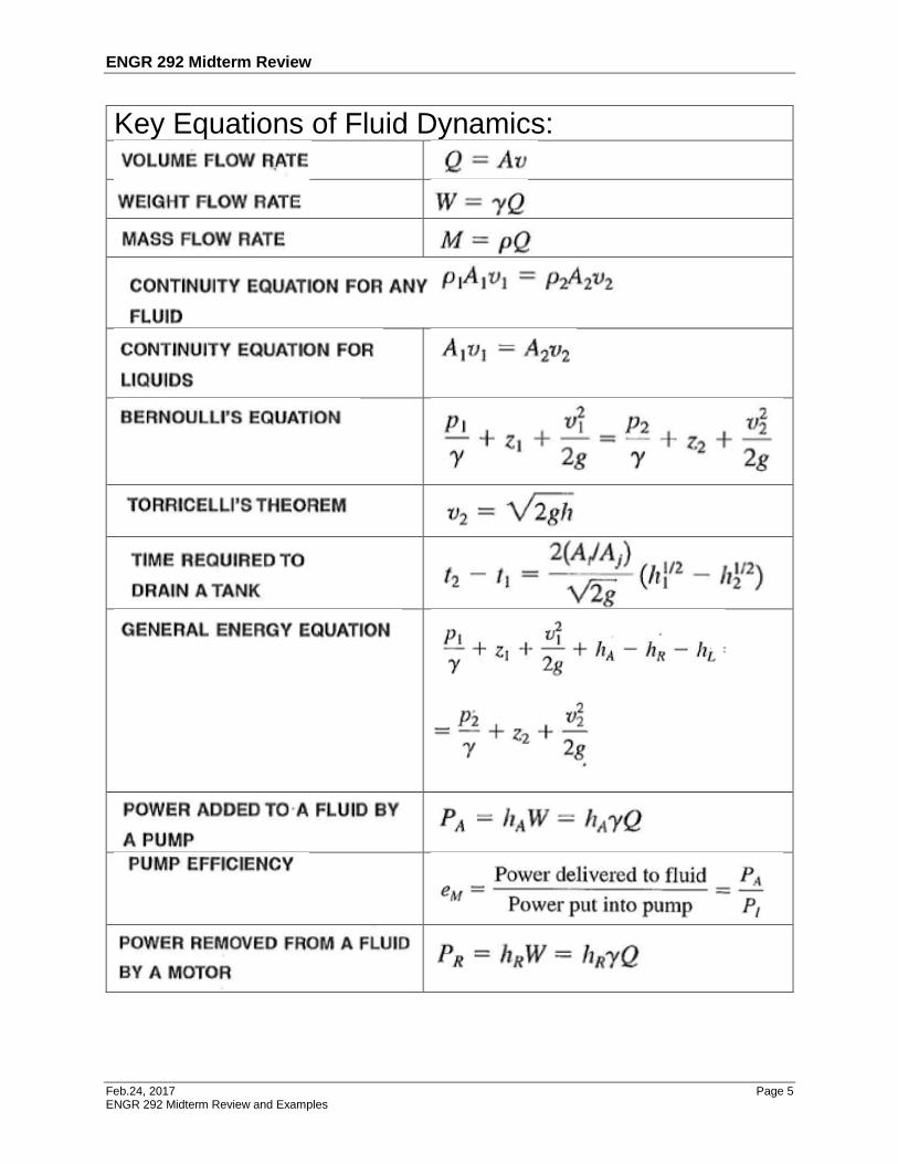
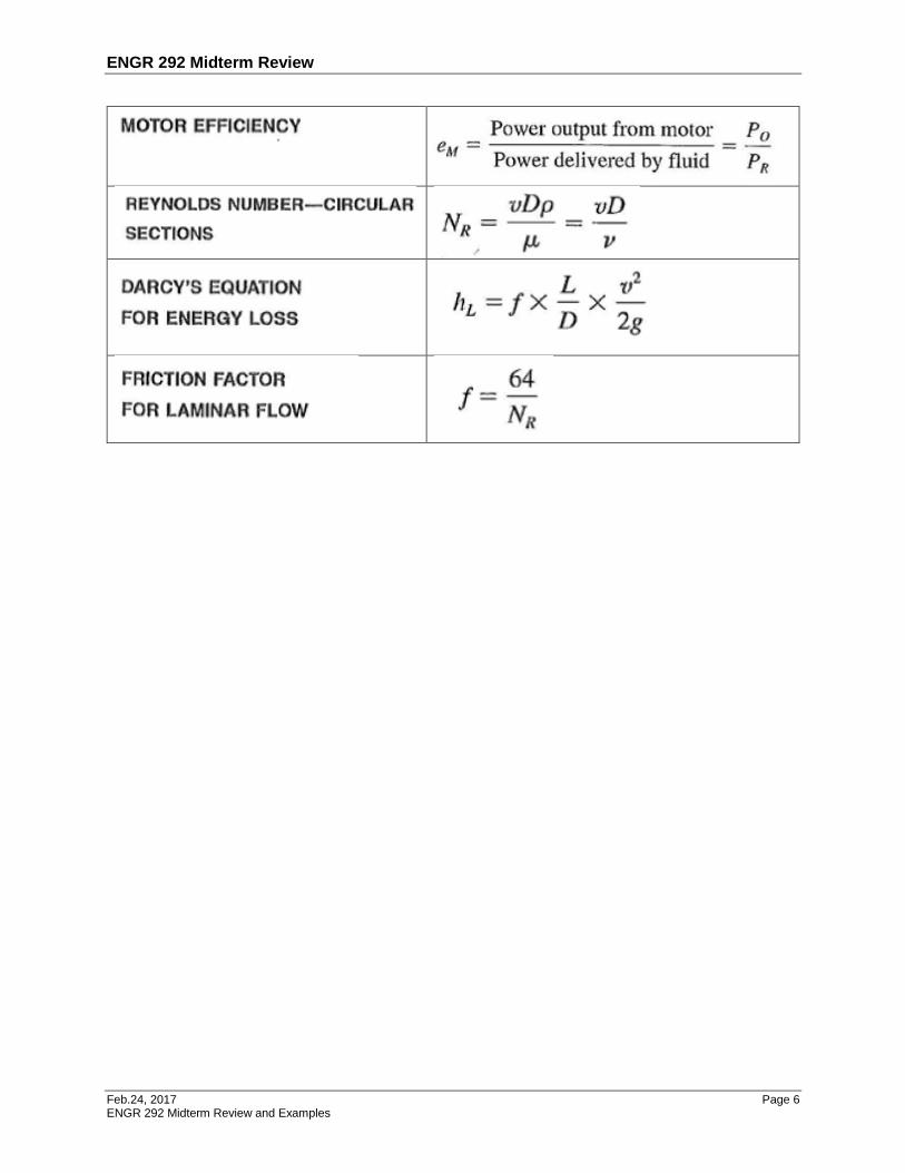
Key Equations of Fluid Dynamics:
ENGR 292 Midterm Review
Feb.24, 2017 Page 6 ENGR 292 Midterm Review and Examples
ENGR 292 Midterm Review
Feb.24, 2017 Page 7 ENGR 292 Midterm Review and Examples
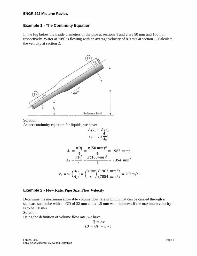
Example 1 - The Continuity Equation In the Fig below the inside diameters of the pipe at sections 1 and 2 are 50 mm and 100 mm
respectively. Water at 70℃ is flowing with an average velocity of 8.0 m/s at section 1. Calculate
the velocity at section 2.
Solution:
As per continuity equation for liquids, we have:
𝐴1v1 = 𝐴2v2
v2 = v1(𝐴1
𝐴2)
𝐴1 =𝜋𝐷1
2
4=
𝜋(50 𝑚𝑚)2
4= 1963 𝑚𝑚2
𝐴2 =𝜋𝐷2
2
4=
𝜋(100𝑚𝑚)2
4= 7854 𝑚𝑚2
v2 = v1 (𝐴1
𝐴2) = (
8.0𝑚
𝑠) (
1963 𝑚𝑚2
7854 𝑚𝑚2) = 2.0 𝑚/𝑠
Example 2 - Flow Rate, Pipe Size, Flow Velocity
Determine the maximum allowable volume flow rate in L/min that can be carried through a
standard steel tube with an OD of 32 mm and a 1.5 mm wall thickness if the maximum velocity
is to be 3.0 m/s.
Solution:
Using the definition of volume flow rate, we have:
𝑄 = 𝐴v
𝐼𝐷 = 𝑂𝐷 − 2 ∗ 𝑇

ENGR 292 Midterm Review
Feb.24, 2017 Page 8 ENGR 292 Midterm Review and Examples
𝐴 =𝜋𝐼𝐷
4
2
= 6.605 × 10⁻⁴ 𝑚2
𝑄 = 𝐴v = [6.605 × 10⁻⁴ 𝑚2] ∗ [3.0 m/s] = 1.982 × 10⁻³ 𝑚3/𝑠
Converting to L/min, we have:
𝑄 = 1.982 × 10⁻³ 𝑚3/𝑠(60000𝐿/𝑚𝑖𝑛
1.0 𝑚3
𝑠
) = 119 𝐿/𝑚𝑖𝑛
Example 3 - Conservation of Energy – Bernoulli’s Equation
In Fig below, water at 10℃ is flowing from section 1 to section 2. At section 1, which is 25 mm
in diameter, the gage pressure is 345 kPa and the velocity of flow is 3.0 m/s. Section 2, which is
50 mm in diameter, is 2.0 m above section 1. Assuming there are no energy losses in the system,
calculate the pressure 𝑝2.
List the items that are known from the problem statement:
𝐷1 = 25 𝑚𝑚; v1 = 3𝑚/𝑠; 𝑧2 − 𝑧1 = 2.0𝑚
𝐷2 = 50 𝑚𝑚; 𝑝1 = 345 𝑘𝑃𝑎𝑔
The pressure 𝑝2 is to be found.
We are going to use Bernoulli’s equation to solve the problem.
ENGR 292 Midterm Review
Feb.24, 2017 Page 9 ENGR 292 Midterm Review and Examples
Here is the Bernoulli’s equation:
𝑝1
𝛾+ 𝑧1 +
v12
2𝑔=
𝑝2
𝛾+ 𝑧2 +
v22
2𝑔
Then
𝑝2
𝛾=
𝑝1
𝛾+ 𝑧1 +
v12
2𝑔− 𝑧2 −
v22
2𝑔
𝑝2 = 𝛾 (𝑝1
𝛾+ 𝑧1 +
v12
2𝑔− 𝑧2 −
v22
2𝑔)
= 𝑝1 + 𝛾 (𝑧1 − 𝑧2 +v1
2 − v22
2𝑔)
Everything was given except 𝑔 , 𝛾 and v2. Of course𝑔 = 9.81 𝑚/𝑠2; Because water at 10℃,
𝛾 = 9.81𝑘𝑁/𝑚3. How can v2 be determined? By the continuity equation:
𝐴1v1 = 𝐴2v2
v2 = 0.75 𝑚/𝑠
𝑝2 = 𝛾 (𝑝1
𝛾+ 𝑧1 +
v12
2𝑔− 𝑧2 −
v22
2𝑔) = 329.6 𝑘𝑃𝑎
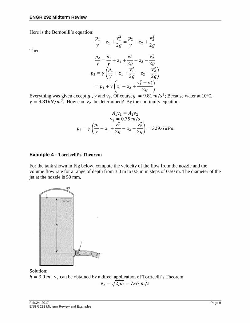
Example 4 - Torricelli’s Theorem
For the tank shown in Fig below, compute the velocity of the flow from the nozzle and the
volume flow rate for a range of depth from 3.0 m to 0.5 m in steps of 0.50 m. The diameter of the
jet at the nozzle is 50 mm.
Solution:
ℎ = 3.0 𝑚, v2 can be obtained by a direct application of Torricelli’s Theorem:
v2 = √2𝑔ℎ = 7.67 𝑚/𝑠
ENGR 292 Midterm Review
Feb.24, 2017 Page 10 ENGR 292 Midterm Review and Examples
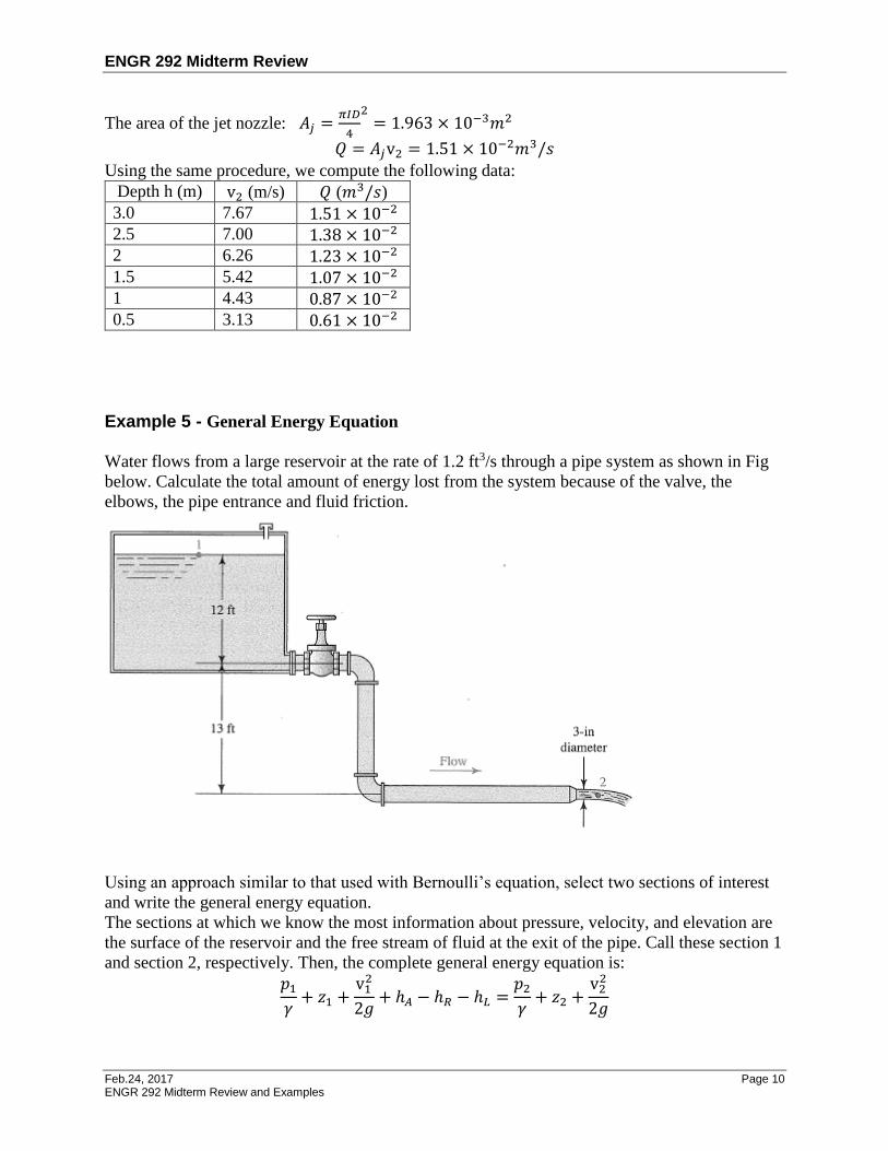
The area of the jet nozzle: 𝐴𝑗 =𝜋𝐼𝐷
4
2= 1.963 × 10⁻³𝑚2
𝑄 = 𝐴𝑗v2 = 1.51 × 10⁻²𝑚3/𝑠
Using the same procedure, we compute the following data:
Depth h (m) v2 (m/s) 𝑄 (𝑚3/𝑠)
3.0 7.67 1.51 × 10⁻²
2.5 7.00 1.38 × 10⁻²
2 6.26 1.23 × 10⁻²
1.5 5.42 1.07 × 10⁻²
1 4.43 0.87 × 10⁻²
0.5 3.13 0.61 × 10⁻²
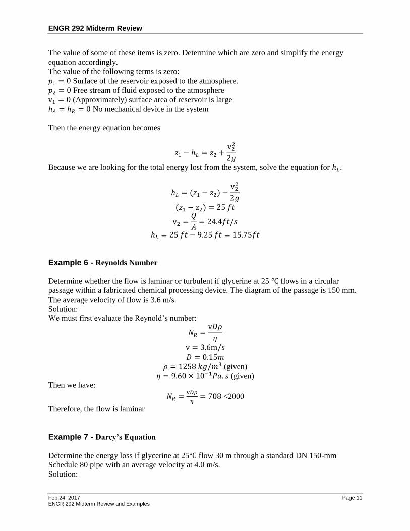
Example 5 - General Energy Equation
Water flows from a large reservoir at the rate of 1.2 ft3/s through a pipe system as shown in Fig
below. Calculate the total amount of energy lost from the system because of the valve, the
elbows, the pipe entrance and fluid friction.
Using an approach similar to that used with Bernoulli’s equation, select two sections of interest
and write the general energy equation.
The sections at which we know the most information about pressure, velocity, and elevation are
the surface of the reservoir and the free stream of fluid at the exit of the pipe. Call these section 1
and section 2, respectively. Then, the complete general energy equation is:
𝑝1
𝛾+ 𝑧1 +
v12
2𝑔+ ℎ𝐴 − ℎ𝑅 − ℎ𝐿 =
𝑝2
𝛾+ 𝑧2 +
v22
2𝑔
ENGR 292 Midterm Review
Feb.24, 2017 Page 11 ENGR 292 Midterm Review and Examples
The value of some of these items is zero. Determine which are zero and simplify the energy
equation accordingly.
The value of the following terms is zero:
𝑝1 = 0 Surface of the reservoir exposed to the atmosphere.
𝑝2 = 0 Free stream of fluid exposed to the atmosphere
v1 = 0 (Approximately) surface area of reservoir is large
ℎ𝐴 = ℎ𝑅 = 0 No mechanical device in the system
Then the energy equation becomes
𝑧1 − ℎ𝐿 = 𝑧2 +v2
2
2𝑔
Because we are looking for the total energy lost from the system, solve the equation for ℎ𝐿.
ℎ𝐿 = (𝑧1 − 𝑧2) −v2
2
2𝑔
(𝑧1 − 𝑧2) = 25 𝑓𝑡
v2 =𝑄
𝐴= 24.4𝑓𝑡/𝑠
ℎ𝐿 = 25 𝑓𝑡 − 9.25 𝑓𝑡 = 15.75𝑓𝑡
Example 6 - Reynolds Number
Determine whether the flow is laminar or turbulent if glycerine at 25 ℃ flows in a circular
passage within a fabricated chemical processing device. The diagram of the passage is 150 mm.
The average velocity of flow is 3.6 m/s.
Solution:
We must first evaluate the Reynold’s number:
𝑁𝑅 =v𝐷𝜌
𝜂
v = 3.6m/s
𝐷 = 0.15𝑚
𝜌 = 1258 𝑘𝑔/𝑚3 (given)
𝜂 = 9.60 × 10⁻¹𝑃𝑎. 𝑠 (given)
Then we have:
𝑁𝑅 =v𝐷𝜌
𝜂= 708 <2000
Therefore, the flow is laminar
Example 7 - Darcy’s Equation
Determine the energy loss if glycerine at 25℃ flow 30 m through a standard DN 150-mm
Schedule 80 pipe with an average velocity at 4.0 m/s.
Solution:
ENGR 292 Midterm Review
Feb.24, 2017 Page 12 ENGR 292 Midterm Review and Examples
First we must determine whether the flow is laminar or turbulent by evaluating the Reynolds
number:
𝑁𝑅 =v𝐷𝜌
𝜂
𝜌 = 1258 𝑘𝑔/𝑚3 (given)
𝜂 = 9.60 × 10⁻¹𝑃𝑎. 𝑠 (given)
𝐷 = 0.1463 𝑚 (given)
𝑁𝑅 =v𝐷𝜌
𝜂= 767 < 2000
The flow is laminar
𝑓 =64
𝑁𝑅=
64
767= 0.0835
Using Darcy’s equation, we get:
ℎ𝐿 = 𝑓 ×L
𝐷×
𝑣2
2𝑔= 13.98 𝑚
Example 8 - Use of the Moody Diagram
Determine the friction factor 𝑓 if water at 160℉ is flowing at 30.0 ft/s in a 1-in schedule 40 steel
pipe.
Solution:
The Reynolds number must first be evaluated to determine whether the flow is laminar or
turbulent:
𝑁𝑅 =v𝐷𝜌
𝜂=
v𝐷
𝑣
𝐷 = 0.0874 𝑓𝑡 (given)
𝑣 = 4.38 × 10⁻⁶𝑓𝑡2/𝑠(given)
𝑁𝑅 =v𝐷𝜌
𝜂=
v𝐷
𝑣= 5.98 × 10⁵
Thus, the flow is turbulent.
Now the relative roughness must be evaluated.
𝜀 = 1.5 × 10⁻⁴ (given)
Then the relative roughness is 𝐷
𝜀= 583
Use of the Moody diagram to find the friction factor 𝑓
Locate the Reynolds number on the abscissa of the Moody diagram
Project vertically until the curve for 𝐷
𝜀 is reached. You must interpolate between the curve for 500
and the one for 750 on the vertical line for 𝑁𝑅 = 5.98 × 10⁵
Project horizontally to the left, and read 𝑓 = 0.023

ENGR 292 Midterm Review
Feb.24, 2017 Page 13 ENGR 292 Midterm Review and Examples
Example 9 - Minor Loss
Determine the energy loss that will occur as 100 L/min of water flows through a sudden
enlargement made from two sizes of copper hydraulic tubing. The small tube is 25 mm OD × 1.5
mm wall; the large tube is 80 m OD × 2.8 mm wall. See Appendix G.2 for tube dimension and
areas.
Resistance Coefficient – sudden enlargement
Solution:
Using the subscript 1 for the section just ahead of the enlargement and subscript 2 for the section
downstream from the enlargement, we get
𝐷1 = 22𝑚𝑚 = 0.022𝑚
𝐴1 = 3.801 × 10⁻⁴𝑚2

ENGR 292 Midterm Review
Feb.24, 2017 Page 14 ENGR 292 Midterm Review and Examples
𝐷2 = 74.4𝑚𝑚 = 0.0744𝑚
𝐴2 = 4.347 × 10⁻³𝑚2
v1 =𝑄1
𝐴1=
100𝐿/𝑚𝑖𝑛
3.801 × 10⁻⁴𝑚2= 4.385𝑚/𝑠
v12
2𝑔=
(4.385)2
2 × 9.81= 0.98 𝑚
To find a value for 𝐾, the diameter ratio is needed. We find that: 𝐷2
𝐷1=
74.4
22= 3.382
From the Figure of Resistance Coefficient – sudden enlargement above, we read 𝐾 = 0.74
Then we have:
ℎ𝐿 = 𝐾 (v1
2
2𝑔) = 0.74 × 0.98 = 0.725𝑚
This result indicates that 0.725 Nm of energy is dissipated from each Newton of water that flow
through the sudden enlargement.
Example 10 – Buoyancy A Cube with volume 1 𝑚3 weighing 200N is attached to a solid concrete block weighing 4.1 kN.
If the concrete has a specific weight of 23.6 𝑘𝑁/𝑚3, will the two objects together float or sink in
water?
Solution:
If both the cube and concrete block are submerged:
Upward forces 𝐹𝑈 = 𝐹𝑏_𝐶𝑢𝑏𝑒 + 𝐹𝑏_𝐶𝑜𝑛𝑐𝑟𝑒𝑡𝐵𝑙𝑜𝑐𝑘 = 𝛾𝑤𝑎𝑡𝑒𝑟𝑉𝑏_𝐶𝑢𝑏𝑒 + 𝛾𝑤𝑎𝑡𝑒𝑟𝑉𝑏_𝐶𝑜𝑛𝑐𝑟𝑒𝑡𝐵𝑙𝑜𝑐𝑘
= 𝛾𝑤𝑎𝑡𝑒𝑟(𝑉𝑏𝐶𝑢𝑏𝑒+ 𝑉𝑏𝐶𝑜𝑛𝑐𝑟𝑒𝑡𝐵𝑙𝑜𝑐𝑘
)
𝑉𝑏𝐶𝑢𝑏𝑒= 1𝑚3
𝑉𝑏𝐶𝑜𝑛𝑐𝑟𝑒𝑡𝐵𝑙𝑜𝑐𝑘=
𝑊𝑏𝐶𝑜𝑛𝑐𝑟𝑒𝑡𝐵𝑙𝑜𝑐𝑘
𝛾𝑏𝐶𝑜𝑛𝑐𝑟𝑒𝑡𝐵𝑙𝑜𝑐𝑘
=4.1𝑘𝑁
23.6𝑘𝑁/𝑚3
= 0.1737𝑚3
𝑉𝑏𝐶𝑢𝑏𝑒+ 𝑉𝑏𝐶𝑜𝑛𝑐𝑟𝑒𝑡𝐵𝑙𝑜𝑐𝑘
= 1.1737𝑚3
𝐹𝑈 = 𝛾𝑤𝑎𝑡𝑒𝑟(𝑉𝑏𝐶𝑢𝑏𝑒+ 𝑉𝑏𝐶𝑜𝑛𝑐𝑟𝑒𝑡𝐵𝑙𝑜𝑐𝑘
)
= 9.81𝑘𝑁/𝑚3 × 1.1737𝑚3
= 11.51𝑘𝑁 Downward forces
𝐹𝐷 = 𝑊𝑏_𝐶𝑢𝑏𝑒 + 𝑊𝑏_𝐶𝑜𝑛𝑐𝑟𝑒𝑡𝐵𝑙𝑜𝑐𝑘 = 0.2𝑘𝑁 +4.1𝑘𝑁 = 4.3𝑘𝑁
𝐹𝑈 > 𝐹𝐷 Therefore, it will float.

ENGR 292 Midterm Review
Feb.24, 2017 Page 15 ENGR 292 Midterm Review and Examples
Example 11 - Forces on Submerge Plane Areas
Forces on submerged plane areas: compute the magnitude of the resultant force on the indicated
area and the location of the center of pressure. Show the resultant force on the area and clearly
dimension its location.
Given:
𝑠𝑔𝑜𝑖𝑙 = 0.85; 𝐷𝐷𝑖𝑠𝑘 = 450mm = 0.45m; , 𝛾𝑤𝑎𝑡𝑒𝑟 𝑎𝑡 4℃ = 9.81 𝑘𝑁/𝑚3
Geometrical sizes of the container in the Figure 4.31
Find:
𝐹𝑅; 𝐿𝑃
Solution:
ℎ𝑐 = 0.45 +1.5 − 0.3
2= 0.825𝑚

ENGR 292 Midterm Review
Feb.24, 2017 Page 16 ENGR 292 Midterm Review and Examples
𝐿𝑐 =ℎ𝑐
𝑐𝑜𝑠30°= 0.953𝑚
𝐴𝐷𝑖𝑠𝑘 =𝜋𝐷𝐷𝑖𝑠𝑘
2
4= 0.159𝑚2
𝛾𝑜𝑖𝑙 = 𝑠𝑔𝑜𝑖𝑙 × 𝛾𝑤𝑎𝑡𝑒𝑟 𝑎𝑡 4℃ = 0.85 × 9.81 𝑘𝑁/𝑚3 = 8.34𝑘𝑁/𝑚3
𝐹𝑅 = 𝛾𝑜𝑖𝑙ℎ𝑐𝐴𝐷𝑖𝑠𝑘 = 8.34𝑘𝑁/𝑚3 × 0.825𝑚 × 0.159𝑚2 = 1.09 𝑘𝑁
𝐼𝑐 =𝜋𝐷𝐷𝑖𝑠𝑘
4
64= 0.002013𝑚4
𝐿𝑃 = 𝐿𝑐 +𝐼𝑐
𝐿𝑐𝐴= 0.953𝑚 +
0.002013𝑚4
0.953𝑚 × 0.159𝑚2= 0.966𝑚
Example 12 – Stability of Floating Bodies
A boat is shown in Fig below. Its geometry at the water line is the same as the top surface. The
hull is solid. It the boat stable?
Given: 𝛾𝑤𝑎𝑡𝑒𝑟 = 9.81 𝑘𝑁/𝑚3
Geometrical sizes of the cylinder in the Figure 5.33
Find:
Stability

ENGR 292 Midterm Review
Feb.24, 2017 Page 17 ENGR 292 Midterm Review and Examples
Solution:
Entire hull:
𝐴1 = 0.6𝑚 × 2.4𝑚/2 = 0.72𝑚2
𝑌1 = 0.60 ×2
3= 0.4𝑚
𝐴2 = 1.2𝑚 × 2.4𝑚 = 2.88𝑚2
𝑌2 = 1.2 ×1
2+ 0.6 = 1.2𝑚
𝐴𝑇 = 𝐴1 + 𝐴2 = 3.60𝑚2
𝑌𝑐𝑔 =𝐴1𝑌1 + 𝐴2𝑌2
𝐴𝑇= 1.04 𝑚
The Submerged portion:
𝐴1 = 0.6𝑚 × 2.4𝑚/2 = 0.72𝑚2
𝑌1 = 0.60 ×2
3= 0.4𝑚
𝐴2′ = 0.9𝑚 × 2.4𝑚 = 2.16𝑚2
𝑌2′ = 0.9 ×
1
2+ 0.6 = 1.05𝑚
𝐴𝑇′ = 𝐴1 + 𝐴2
′ = 2.88 𝑚2
𝑌𝑐𝑔 =𝐴1𝑌1 + 𝐴2
′ 𝑌2′
𝐴𝑇′ = 0.89 𝑚
𝑉𝑑 = 𝐴𝑇′ × 5.5𝑚 = 15.84 𝑚3
𝐼 = 5.5𝑚 × (2.4𝑚)3/12 = 6.336𝑚4
𝑀𝐵 =𝐼
𝑉𝑑= 0.40𝑚
𝑌𝑚𝑐 = 𝑌𝑐𝑏 + 𝑀𝐵 = 0.89𝑚 + 0.40𝑚 =1.29𝑚 > 𝑌𝑐𝑔
Therefore,
The hull is stable
ENGR 292 Midterm Review
Feb.24, 2017 Page 18 ENGR 292 Midterm Review and Examples
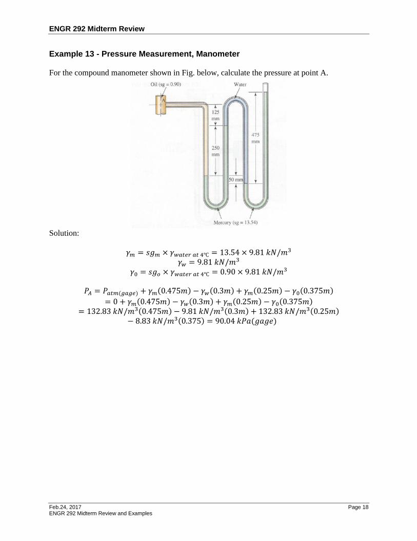
Example 13 - Pressure Measurement, Manometer
For the compound manometer shown in Fig. below, calculate the pressure at point A.
Solution:
𝛾𝑚 = 𝑠𝑔𝑚 × 𝛾𝑤𝑎𝑡𝑒𝑟 𝑎𝑡 4℃ = 13.54 × 9.81 𝑘𝑁/𝑚3
𝛾𝑤 = 9.81 𝑘𝑁/𝑚3
𝛾0 = 𝑠𝑔𝑜 × 𝛾𝑤𝑎𝑡𝑒𝑟 𝑎𝑡 4℃ = 0.90 × 9.81 𝑘𝑁/𝑚3
𝑃𝐴 = 𝑃𝑎𝑡𝑚(𝑔𝑎𝑔𝑒) + 𝛾𝑚(0.475𝑚) − 𝛾𝑤(0.3𝑚) + 𝛾𝑚(0.25𝑚) − 𝛾0(0.375𝑚)
= 0 + 𝛾𝑚(0.475𝑚) − 𝛾𝑤(0.3𝑚) + 𝛾𝑚(0.25𝑚) − 𝛾0(0.375𝑚)
= 132.83 𝑘𝑁/𝑚3(0.475𝑚) − 9.81 𝑘𝑁/𝑚3(0.3𝑚) + 132.83 𝑘𝑁/𝑚3(0.25𝑚)− 8.83 𝑘𝑁/𝑚3(0.375) = 90.04 𝑘𝑃𝑎(𝑔𝑎𝑔𝑒)


