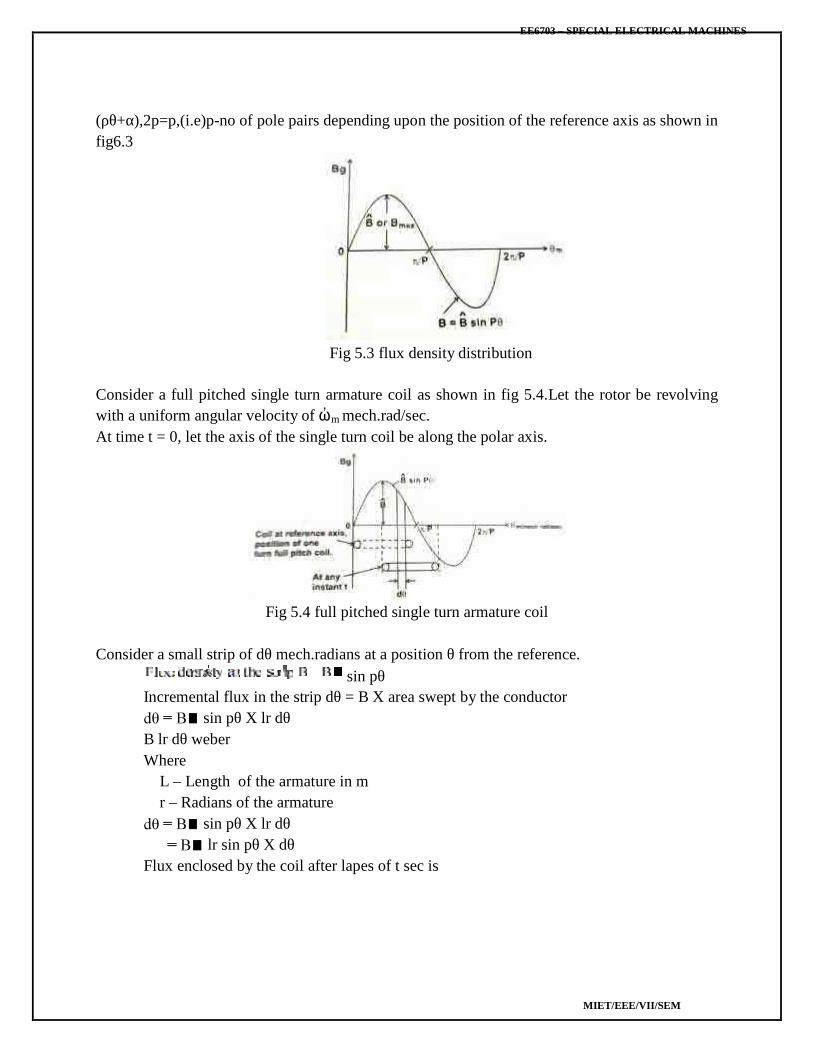
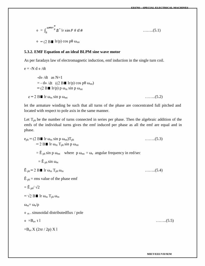
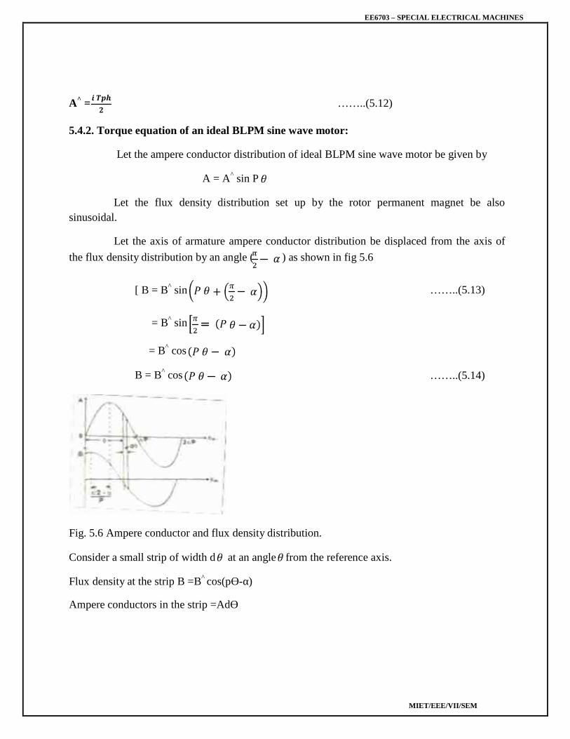
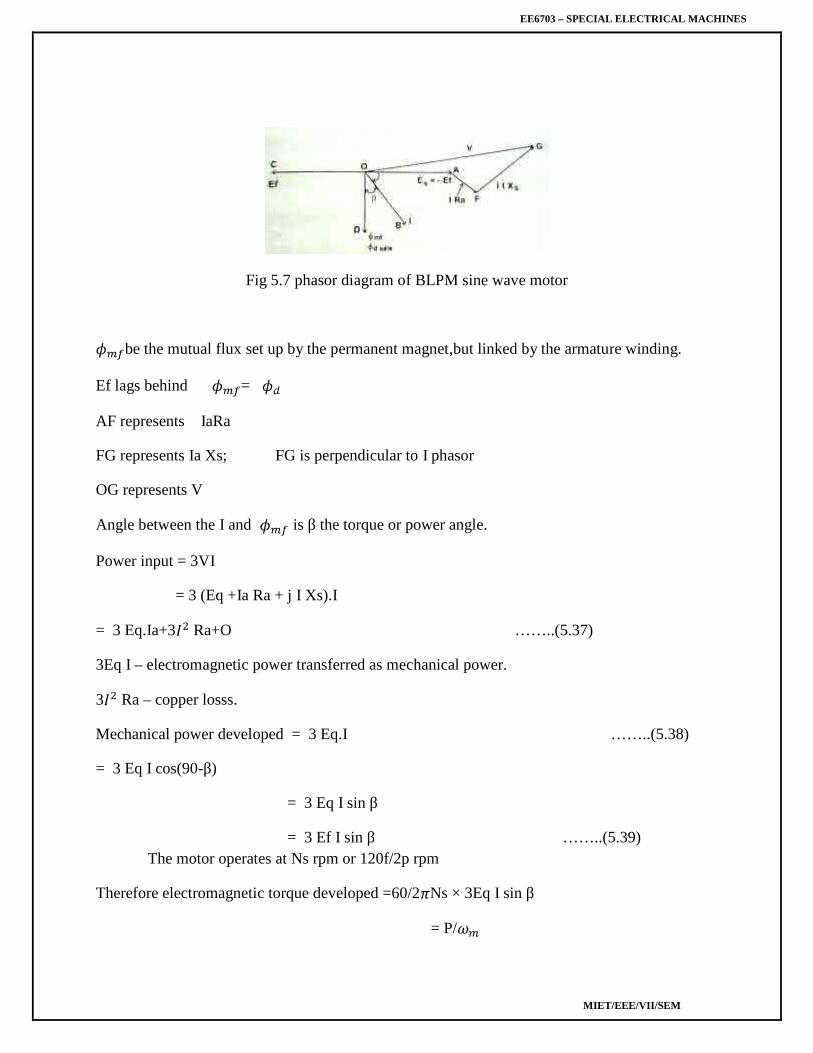
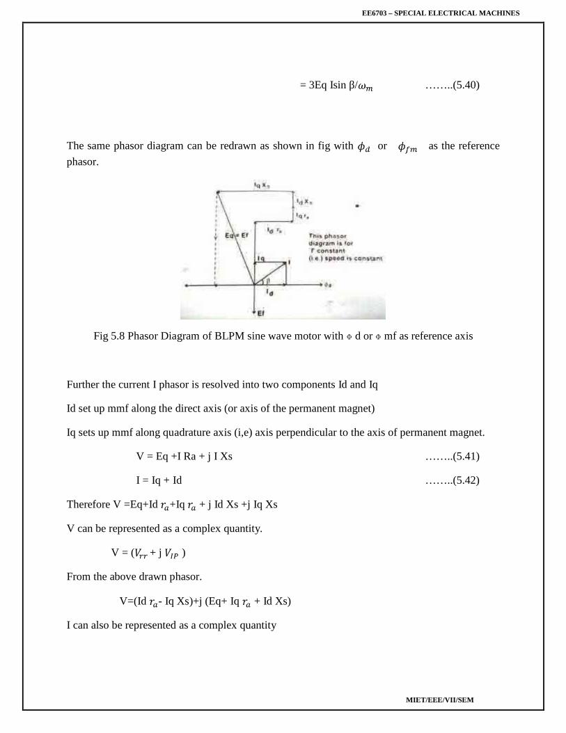
EE6703 – SPECIAL ELECTRICAL MACHINES MIET/EEE/VII/SEM M.I.E.T. ENGINEERING COLLEGE (Approved by AICTE and Affiliated to Anna University Chennai) TRICHY – PUDUKKOTTAI ROAD, TIRUCHIRAPPALLI – 620 007 DEPARTMENT OF ELECTRICAL AND ELECTRONICS ENGINEERING COURSE MATERIAL EE6703- SPECIAL ELECTRICAL MACHINES IV YEAR/VII SEMESTER
Transcript
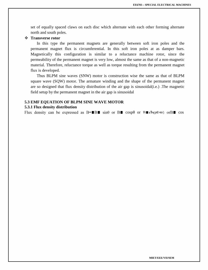
EE6703 – SPECIAL ELECTRICAL MACHINES
MIET/EEE/VII/SEM
M.I.E.T. ENGINEERING COLLEGE(Approved by AICTE and Affiliated to Anna University Chennai)
DEPARTMENT OF ELECTRICAL ANDELECTRONICS ENGINEERING
COURSE MATERIAL
EE6703- SPECIAL ELECTRICAL MACHINES
IV YEAR/VII SEMESTER
EE6703 – SPECIAL ELECTRICAL MACHINES
MIET/EEE/VII/SEM
DEPARTMENT OF ELECTRICAL AND ELECTRONICS ENGINEERING(SYLLABUS)
Sub Code : EE6703 Branch/Year/Sem: EEE/IV/VIISub Name : Special Electrical Machines Batch : 2016 - 2020Staff Name : Mr.D.Tamilselvan Academic Year : 2019 – 2020
UNIT I SYNCHRONOUS RELUCTANCE MOTORS 9Constructional features – Types – Axial and Radial flux motors – Operating principles – Variable ReluctanceMotors – Voltage and Torque Equations - Phasor diagram - performance characteristics – Applications.
UNIT II STEPPER MOTORS 9Constructional features – Principle of operation – Variable reluctance motor – Hybrid motor – Single andmulti stack configurations – Torque equations – Modes of excitation – Characteristics – Drive circuits– Microprocessor control of stepper motors – Closed loop control-Concept of lead angle– Applications.
UNIT III SWITCHED RELUCTANCE MOTORS (SRM) 9Constructional features – Rotary and Linear SRM - Principle of operation – Torque production –Steady state performance prediction- Analytical method -Power Converters and their controllers – Methodsof Rotor position sensing – Sensor less operation – Characteristics and Closed loop control – Applications.
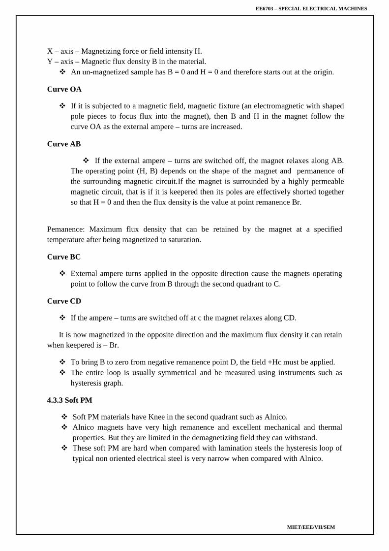
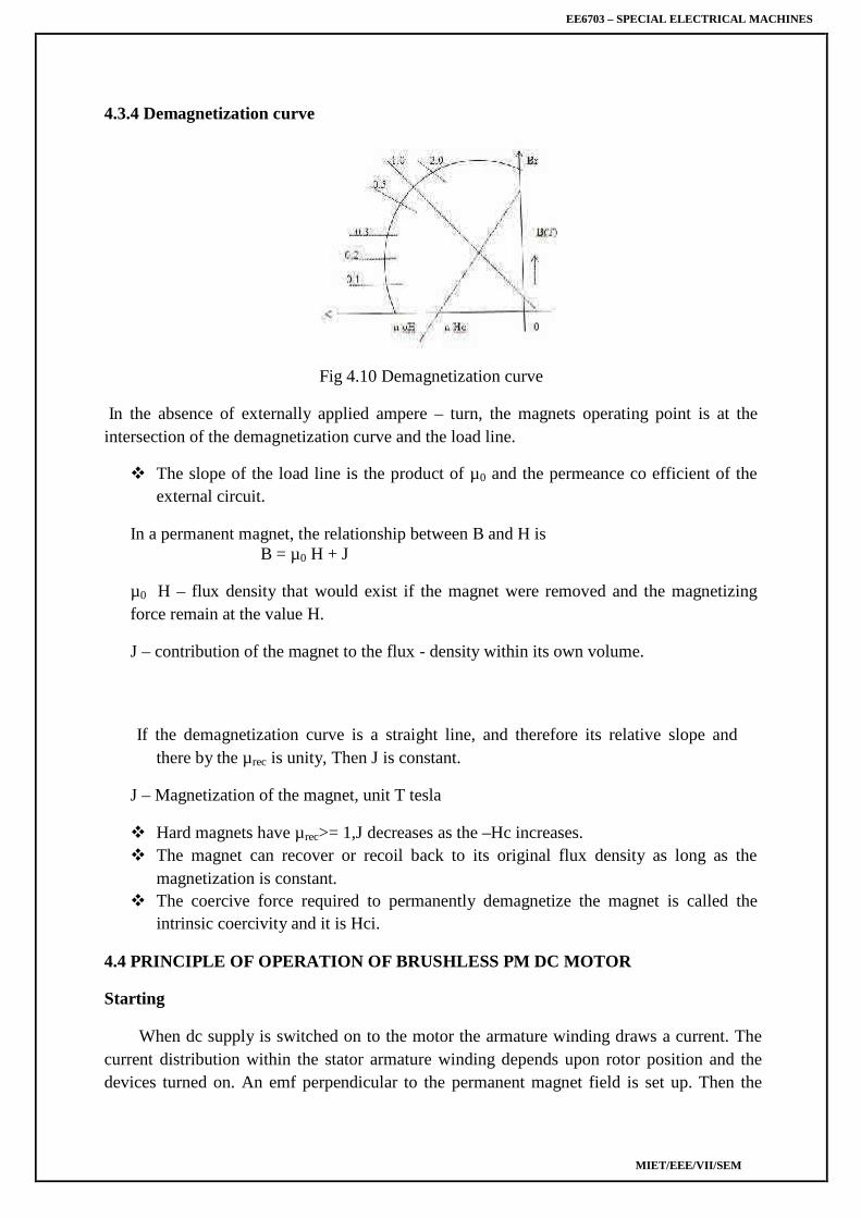
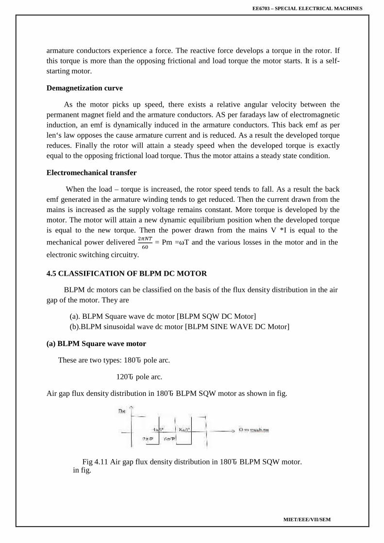
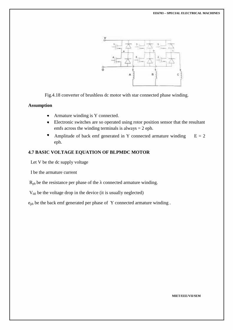
UNIT IV PERMANENT MAGNET BRUSHLESS D.C. MOTORS 9Permanent Magnet materials – Minor hysteresis loop and recoil line-Magnetic Characteristics –Permeance coefficient -Principle of operation – Types – Magnetic circuit analysis – EMF and torqueequations –Commutation - Power Converter Circuits and their controllers – Motor characteristicsand control– Applications.
UNIT V PERMANENT MAGNET SYNCHRONOUS MOTORS (PMSM) 9Principle of operation – Ideal PMSM – EMF and Torque equations – Armature MMF – SynchronousReactance – Sine wave motor with practical windings - Phasor diagram – Torque/speed characteristics- Power controllers - Converter Volt-ampere requirements– Applications.
TEXT BOOKS:1. K.Venkataratnam, ‘Special Electrical Machines’, Universities Press (India) Private Limited, 2008.2. T.J.E. Miller, ‘Brushless Permanent Magnet and Reluctance Motor Drives’, Clarendon Press,Oxford, 1989.3. T. Kenjo, ‘Stepping Motors and Their Microprocessor Controls’, Clarendon Press London, 1984.
REFERENCES:1. R.Krishnan, ‘Switched Reluctance Motor Drives – Modeling, Simulation, Analysis, Design andApplication’, CRC Press, New York, 2001.2. P.P. Aearnley, ‘Stepping Motors – A Guide to Motor Theory and Practice’, Peter PerengrinusLondon, 1982.3. T. Kenjo and S. Nagamori, ‘Permanent Magnet and Brushless DC Motors’, Clarendon Press,London, 1988.
SUBJECT IN – CHARGE HOD
L T P C3 0 0 3
EE6703 – SPECIAL ELECTRICAL MACHINES
MIET/EEE/VII/SEM
M.I.E.T. ENGINEERING COLLEGE(Approved by AICTE and Affiliated to Anna University Chennai)
1. To impart knowledge on Construction, principle of operation and performance of ynchronousreluctance motors.
2. To impart knowledge on the Construction, principle of operation, control and performance ofstepping motors.
3. To impart knowledge on the Construction, principle of operation, control and performance ofswitched reluctance motors.
4. To impart knowledge on the Construction, principle of operation, control and performance ofpermanent magnet brushless D.C. motors.
5. To impart knowledge on the Construction, principle of operation and performance of permanentmagnet synchronous motors.
COURSE OUTCOMES
1. Explain the necessity to improve the saliency of synchronous reluctance motorand its characteristics
2. Compare the various methods of excitation of different types of stepper motorand its driver circuits
3. Describe the operation of switched reluctance motor with and without sensors
4. Explain the electronic commutation of permanent magnet brushless D.C. motorsand develop the torque equation.
5. Develop the expression for emf and torque of permanent magnet synchronousmotors and discuss power controller for permanent magnet synchronous motors.
Prepared by Verified by
D.Tamilselvan HOD/EEE
Approved byPRINCIPAL
Sub Code : EE6703 Branch/Year/Sem: EEE/IV/VIISub Name : Special Electrical Machines Batch : 2016 - 2020Staff Name : Mr.D.Tamilselvan Academic Year : 2019 - 2020
EE6703 – SPECIAL ELECTRICAL MACHINES
MIET/EEE/VII/SEM
M.I.E.T. ENGINEERING COLLEGE(Approved by AICTE and Affiliated to Anna University Chennai)
TRICHY – PUDUKKOTTAI ROAD, TIRUCHIRAPPALLI – 620 007UNIT I
SYNCHRONOUS RELUCTANCE MOTORSConstructional features – Types – Axial and Radial flux motors – Operating principles – VariableReluctance Motors – Voltage and Torque Equations - Phasor diagram - performance characteristics– Applications.
1.1 CONSTRUCTION OF SYNCHRONOUS RELUCTANCE MOTOR
The structure of reluctance motor is same as that of salient pole synchronous machineas shown in fig. The rotor does not have any field winding .The stator has three phasesymmetrical winding, which creates sinusoidal rotating magnetic field in the air gap, and thereluctance torque is developed because the induced magnetic field in the rotor has a tendencyto cause the rotor to align with the stator field at a minimum reluctance position
Fig 1.1 Idealized Three Phase Four Pole Synchronous Machine (Salient Pole)
EE6703 – SPECIAL ELECTRICAL MACHINES
MIET/EEE/VII/SEM
Fig 1.2 Cross Section of Synchronous Reluctance Motor.
The rotor of the modern reluctance machine is designed with iron laminations in theaxial direction separated by non-magnetic material. The performance of the reluctance motormay approach that of induction machine. With high saliency ratio a power factor oh 0.8 canbe reached. The efficiency of a reluctance machine may be higher than an induction motor
because there is no rotor copper loss. Because of inherent simplicity, robustness ofconstruction and low cost.
The synchronous reluctance motor has no synchronous starting torque and runs upfrom stand still by induction action. There is an auxiliary starting winding. This has increasedthe pull out torque, the power factor and the efficiency.
Synchronous reluctance motor is designed for high power applications. It can broadly beclassified into
Axially laminated and
Radially laminated.
Fig.1.3 cross section of axially laminated
Reluctance motors can deliver very high power density at low cost, making them ideal formany applications. Disadvantages are high torque ripple (the difference between maximumand minimum torque during one revolution) when operated at low speed, and noise caused bytorque ripple. Until the early twenty-first century their use was limited by the complexity of
EE6703 – SPECIAL ELECTRICAL MACHINES
MIET/EEE/VII/SEM
designing and controlling them. These challenges are being overcome by advances in thetheory, by the use of sophisticated computer design tools, and by the use of low-cost embedded systems for control, typically based on microcontrollers using controlalgorithms and real-time computing to tailor drive waveforms according to rotor position and
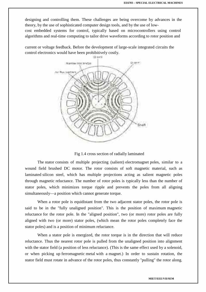
current or voltage feedback. Before the development of large-scale integrated circuits thecontrol electronics would have been prohibitively costly.
Fig 1.4 cross section of radially laminated
The stator consists of multiple projecting (salient) electromagnet poles, similar to a
wound field brushed DC motor. The rotor consists of soft magnetic material, such as
laminated silicon steel, which has multiple projections acting as salient magnetic poles
through magnetic reluctance. The number of rotor poles is typically less than the number of
stator poles, which minimizes torque ripple and prevents the poles from all aligning
simultaneously—a position which cannot generate torque.
When a rotor pole is equidistant from the two adjacent stator poles, the rotor pole is
said to be in the "fully unaligned position". This is the position of maximum magnetic
reluctance for the rotor pole. In the "aligned position", two (or more) rotor poles are fully
aligned with two (or more) stator poles, (which mean the rotor poles completely face the
stator poles) and is a position of minimum reluctance.
When a stator pole is energized, the rotor torque is in the direction that will reduce
reluctance. Thus the nearest rotor pole is pulled from the unaligned position into alignment
with the stator field (a position of less reluctance). (This is the same effect used by a solenoid,
or when picking up ferromagnetic metal with a magnet.) In order to sustain rotation, the
stator field must rotate in advance of the rotor poles, thus constantly "pulling" the rotor along.
EE6703 – SPECIAL ELECTRICAL MACHINES
MIET/EEE/VII/SEM
Some motor variants will run on 3-phase AC power (see the synchronous reluctance variant
below). Most modern designs are of the switched reluctance type, because
electronic commutation gives significant control advantages for motor starting, speed control,
and smooth operation (low torque ripple).
Dual-rotor layouts provide more torque at lower price per volume or per mass.[The inductance of each phase winding in the motor will vary with position, because the
reluctance also varies with position. This presents a control systems challenge.
Applications Some washing machine designs. Control rod drive mechanisms of nuclear reactors. The Dyson Digital Motor used in some products produced by the Dyson company.
1.2 ROTOR DESIGN
1.2.1 Salient rotor (Segmental)
Salient rotor shape such that the quadrature air gap is much larger than the direct air gap. Thisyields reactively small Ld/Lqrations in the range of 2.3.
Fig.1.5 Salient rotor
Salient rotor design is as shown. The low Ld. /Lqratios are largely the result ofcirculating flux in the pole faces of the rotor. However the ruggedness and simplicity of therotor structure has encouraged for high speed applications.
1.2.2 Radially Laminated Rotor (Flux Barrier)
Another approach is to use laminations with flux barriers punched into thesteel for a 4 pole machine. The flux barriers and the central hole of the lamination requiredfor the shaft weaken the rotor structurally and thus make this approach a poor choice for highspeed design.
Fig.1.6 Radially Laminated Rotor
EE6703 – SPECIAL ELECTRICAL MACHINES
MIET/EEE/VII/SEM
1.2.3 Axially Laminated Rotor
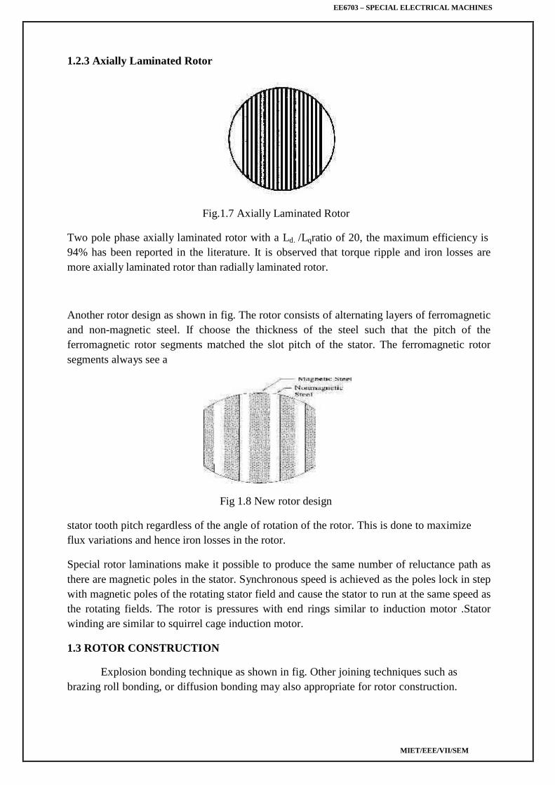
Fig.1.7 Axially Laminated Rotor
Two pole phase axially laminated rotor with a Ld. /Lqratio of 20, the maximum efficiency is94% has been reported in the literature. It is observed that torque ripple and iron losses aremore axially laminated rotor than radially laminated rotor.
Another rotor design as shown in fig. The rotor consists of alternating layers of ferromagneticand non-magnetic steel. If choose the thickness of the steel such that the pitch of theferromagnetic rotor segments matched the slot pitch of the stator. The ferromagnetic rotorsegments always see a
Fig 1.8 New rotor design
stator tooth pitch regardless of the angle of rotation of the rotor. This is done to maximizeflux variations and hence iron losses in the rotor.
Special rotor laminations make it possible to produce the same number of reluctance path asthere are magnetic poles in the stator. Synchronous speed is achieved as the poles lock in stepwith magnetic poles of the rotating stator field and cause the stator to run at the same speed asthe rotating fields. The rotor is pressures with end rings similar to induction motor .Statorwinding are similar to squirrel cage induction motor.
1.3 ROTOR CONSTRUCTION
Explosion bonding technique as shown in fig. Other joining techniques such asbrazing roll bonding, or diffusion bonding may also appropriate for rotor construction.
EE6703 – SPECIAL ELECTRICAL MACHINES
MIET/EEE/VII/SEM
First sheets of ferromagnetic and non-ferromagnetic steel are bonded. The bondedsheets are then cut into rectangular blocks h\which are machined into the desired rotor. Therotor shaft can also be machined out of the same block as the rotor.
Fig 1.9 Explosion bonding
The rotor joining technique known as explosion bonding. Explosion bonding usesexplosive energy to force two or more metal sheets together at high pressures. Conventionallythe high pressure causes several atomic layers on the surface of each sheet to behave as afluid. The angle of collision between the two metals forces this fluid to jet outward.Effectively cleaning the metal surface, these ultra clean surfaces along with the high pressureforcing the metal plates together provide the necessary condition for solid phase welding.
Experimental tests on a stainless steel/mild steel bond indicate that the tensile andfatigue strengths of the bond are greater than those of either of the component materials dueto the shock hardening which occurs during the process. The bond was also subjected to 10cycles of temperature variation from 20° C - 70°C, with no significant reduction in tensilestrength.
1.4 WORKING OF SYNCHRONOUS RELUCTANCE MOTOR
In order to understand the working of synchronous reluctance motor, when a piece ofmagnetic material is located in a magnetic field, a force acts on the material tending to bringit into the desert portion of the field. The force tends to align the specimen of the material insuch a way that the reluctance of the magnetic path that passes through the material will beminimum.
When supply is given to the stator winding, the revolving magnetic field will exert reluctancetorque on the unsymmetrical rotor tending to align the salient pole axis of the rotor with theaxis of the revolving magnetic field, because in this position, the reluctance of the magneticpath would be minimum. If the reluctance torque is sufficient to start the motor and its load,the rotor will pull into step with the revolving field and continue to run at the speed of therevolving field. Actually the motor starts as an induction motor and after it has reached itsmaximum speed as an induction motor, the reluctance torque pulls its rotor into step with therevolving field, motor now runs as synchronous motor by virtue of its saliency.
EE6703 – SPECIAL ELECTRICAL MACHINES
MIET/EEE/VII/SEM
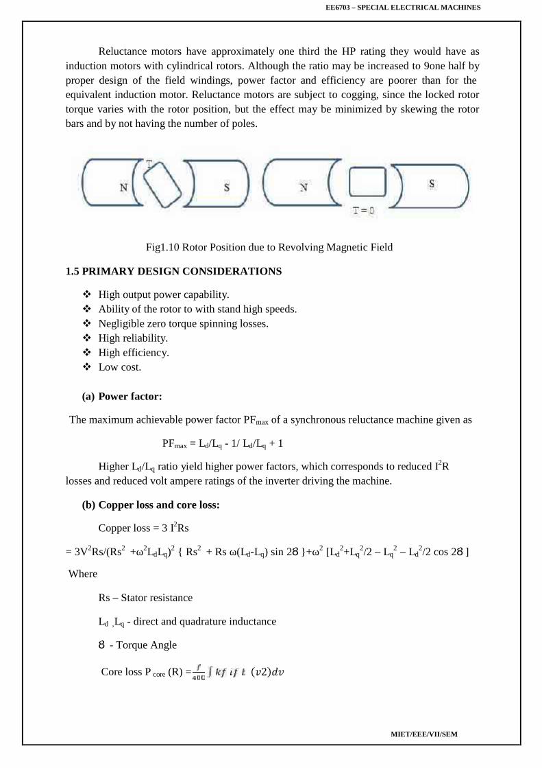
Reluctance motors have approximately one third the HP rating they would have asinduction motors with cylindrical rotors. Although the ratio may be increased to 9one half byproper design of the field windings, power factor and efficiency are poorer than for theequivalent induction motor. Reluctance motors are subject to cogging, since the locked rotortorque varies with the rotor position, but the effect may be minimized by skewing the rotorbars and by not having the number of poles.
Fig1.10 Rotor Position due to Revolving Magnetic Field
1.5 PRIMARY DESIGN CONSIDERATIONS
High output power capability. Ability of the rotor to with stand high speeds. Negligible zero torque spinning losses. High reliability. High efficiency. Low cost.
(a) Power factor:
The maximum achievable power factor PFmax of a synchronous reluctance machine given as
PFmax = Ld/Lq - 1/ Ld/Lq + 1
Higher Ld/Lq ratio yield higher power factors, which corresponds to reduced I2Rlosses and reduced volt ampere ratings of the inverter driving the machine.
The core losses are calculated corresponding to the fundamental component of fluxdensity in the stator iron core. There will also be significant core losses in the stator and rotordue to the winding and slot harmonics. The losses are difficult to estimate reliably.
1.6 TORQUE – SPEED CHARACTERISTICS
The torque speed characteristic of synchronous reluctance motor is shown in fig. Themotor starts at anywhere from 300 to 400 percent of its full load torque (depending on therotor position of the unsymmetrical rotor with respect to the field winding) as a two phasemotor. As a result of the magnetic rotating field created by a starting and running windingdisplaced 90° in both space and time.
At about ¾th of the synchronous speed a centrifugal switch opens the starting windingand the motor continues to develop a single phase torque produced by its running windingonly. As it approaches synchronous speed, the reluctance torque is sufficient to pull the rotorinto synchronism with the pulsating single phase field. The motor operates at constant speedup to a little over 20% of its full load torque. If it is loaded beyond the value of pull outtorque, it will continue to operate as a single phase induction motor up to 500% of its ratedspeed.
Application Characteristics:
Comparable power density but better efficiency than induction motor. Slightly lower power factor than induction motor. Slightly small field weakening range than induction motor. High cost than induction motor but lower than any type of PM motors. Need speed synchronization to inverter out frequency by rotor position sensor sensor
less control. Sensor less control is much easier due to motor saliency. By adding squirrel cage induction motor to synchronous reluctance motor one obtains
line starting reluctance moors. Line started reluctance motors can be parallel with open loop control if the load does
not change suddenly. Other combinations are possible such as adding PM for improved
EE6703 – SPECIAL ELECTRICAL MACHINES
MIET/EEE/VII/SEM
performance Rotor design for best manufacturability is still being optimized especially for high
speed applications.
1.7 PHASER DIAGRAM OF SYNCHRONOUS RELUCTANCE MOTOR
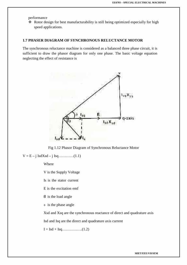
The synchronous reluctance machine is considered as a balanced three phase circuit, it issufficient to draw the phasor diagram for only one phase. The basic voltage equationneglecting the effect of resistance is
Fig 1.12 Phasor Diagram of Synchronous Reluctance Motor
V = E – j IsdXsd – j Isq…………(1.1)
Where
V is the Supply Voltage
Is is the stator current
E is the excitation emf
Ȣ is the load angle
ɸ is the phase angle
Xsd and Xsq are the synchronous reactance of direct and quadrature axis
Isd and Isq are the direct and quadrature axis current
I = Isd + Isq…………….(1.2)
EE6703 – SPECIAL ELECTRICAL MACHINES
MIET/EEE/VII/SEM
Isd is in phase quadrtur with E and Isq is in phasew.
V = E – j IsdXsd – j IsqXsq
From phasor diagram
V cosȢ = E + Isd + Xsd ………………(1.3)
Isd =
IsqXsq = V sinȢ
Isq = ………………..(1.4)
Is cos = Isq cosȢ - Isd sin……………(1.5)
Where
Xsd and Xsq are synchronous reactance of d and q axis.
Sub (3) and (4) in Equ (5)
Is cos ɸ = + …………………(1.6)
P = 3 Vis cos ɸ ………………….(1.7)
Sub equ (6) in equ (7)
Pm = 3 [ sin +V 2 sin2 Ȣ ]
Pm = T ωs
T = Pm/ωs
sinȢ + sin 2Ȣ ]……………(1.8)
Sub E = 0
T = V2 [ ] sin 2Ȣ …………….(1.9)
Equation (9) is the torque equation of synchronous reluctancemotor.
EE6703 – SPECIAL ELECTRICAL MACHINES
MIET/EEE/VII/SEM
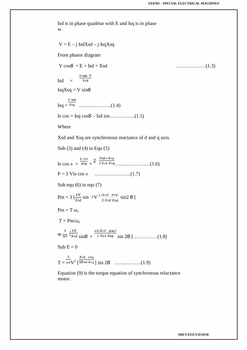
Fig 1.13 Torque Angle Characteristics of Salient Pole Machine
Plotting the equation (9) as shown in fig indicates that the stability limit is reached at Ȣ=± /4
And by increasing g load angle torque also increases.
V2 [ ] sin 2 ȣ = reluctance Power
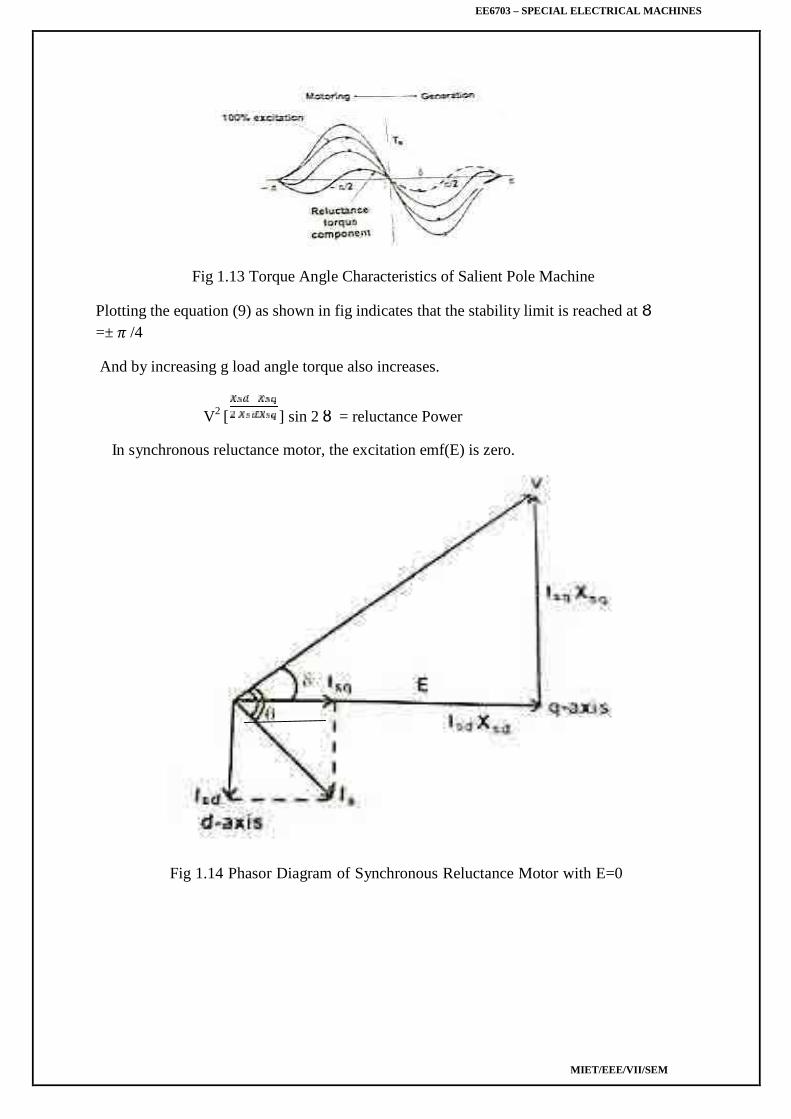
In synchronous reluctance motor, the excitation emf(E) is zero.
Fig 1.14 Phasor Diagram of Synchronous Reluctance Motor with E=0
EE6703 – SPECIAL ELECTRICAL MACHINES
MIET/EEE/VII/SEM
1.8 ADVANTAGES AND DISADVANTAGES OF SYNCHRONOUS RELUCTANCEMOTOR
Advantages There is no concern with demagnetization; hence synchronous reluctance machines
are inherently more reliable than PM machines. There need not be any exciting field as torque is zero, thus eliminating electromagnetic
spinning losses. Synchronous reluctance machine rotors can be constructed entirely from high
strength, low cost materials.
Disadvantages
High cost than induction Motor. Need Speed synchronization to invertor output frequency by using rotor position
sensor and sensor less control. Compared to induction motor it is slightly heavier and has low power factor. By increasing the saliency ratio Lds/Lqs, the power factor can be improved.
1.9 APPLICATIONS OF SYNCHRONIZATION
Metering Pumps. Auxiliary time Mechanism. Wrapping and folding Machines. Proportioning Devices on Pumps or conveyors. Synthetic fibre manufacturing equipment. Processing continuous sheet or film material.
EE6703 – SPECIAL ELECTRICAL MACHINES
MIET/EEE/VII/SEM
UNIT IISTEPPER MOTORS
Constructional features – Principle of operation – Variable reluctance motor – Hybrid motor – Singleand multi-stack configurations – Torque equations – Modes of excitation – Characteristics – Drivecircuits – Microprocessor control of stepper motors – Closed loop control-Concept of lead angle–Applications.
2.1 INTRODUCTION
It is an electrodynamics and electromagnetic equipment.
These motors are also referred to as step motors or stepping motors.
On account of its unusual construction, operation and characteristics it is difficult todefine a stepper motor. Definition given in British Standard specification (BSS) is
A stepper motor is brushless dc motor whose rotor rotates in discrete angulardisplacements when its stator windings are energized in a programmed manner. Rotationoccurs because of magnetic interaction between rotor poles and poles of the sequentiallyenergized winding. The rotor has no electrical windings, but has salient and magnetic/ormagnetized poles.
The stepper motor is a digital actuator whose input is in the form of digital signals andwhose output is in the form of discrete angular rotation. The angular rotation is dependent onthe number of input pulses the motor is suitable for controlling the position by controlling thenumber of input pulses. Thus they are identically suited for open position and speed control.
Applications:
Printers Graph plotters Tape driver Disk Drives Machine Tools X-Y Recorders Robotics space Vehicle IC Fabrication and Electric Watches
2.2 CLASSIFICATION OF STEPPER MOTORS
As construction is concerned stepper motors may be divided into two major groups.
1. Without Permanent Magnet (PM)(a) Single Stack(b) Multi Stack
2. With Permanent Magnet(a) Claw Pole Motor(b) Hybrid Motors
EE6703 – SPECIAL ELECTRICAL MACHINES
MIET/EEE/VII/SEM
2.3 SINGLE STACK VARIABLE RELUCTANCE STEPPER MOTOR
2.3.1 Construction:
The VR stepper motor characterized by the fact there is no permanent magnet either on therotor or the stator. The construction of a 3-phase VR stepper motor with 6 poles on the statorand 4-pole on the rotor as shown.
Fig 2.1 Single Stack Variable Reluctance Stepper Motor
The Stator is made up of silicon steel stampings with inward projected even or oddnumber of poles or teeth. Each and every stator poles carries a field coil an exciting coil. Incase of even number of poles the exciting coils of opposite poles are connected in series. Thetwo coils are connected such that their MMF gets added .the combination of two coils isknown as phase winding.
The rotor is also made up of silicon steel stampings with outward projected poles andit does not have any electrical windings. The number of rotor poles should be different fromthat of stators in order to have self-starting capability and bi direction. The width of rotorteeth should be same as stator teeth. Solid silicon steel rotors are extensively employed. Boththe stator and rotor materials must have lowering a high magnetic flux to pass through themeven if a low magneto motive force is applied.
2.3.2 Electrical Connection
Electrical connection of VR stepper as shown fig. Coil A and A‘ are connected inseries to form a phase winding. This phase winding is connected to a DC source with the helpof semiconductor switch S1.Similary B and B‘ and C and C‘ are connected to the samesource through semiconductor switches S2 and S3 respectively. The motor has 3 –phases a, band c. a phase consist of A and A‘ Coils b phase consist of B and B‘ Coils
EE6703 – SPECIAL ELECTRICAL MACHINES
MIET/EEE/VII/SEM
c phase consist of C and C‘ Coils
2.3.3 Principle of Operation
It works on the principle of variable reluctance. The principle of operation of VRstepper motor explained by referring fig.
(a).Mode 1 : One phase ON or full step operation
In this mode of operation of stepper motor only one phase is energized at any time. Ifcurrent is applied to the coils of phase ‗a‘ (or) phase ‗a‘ is excited, the reluctance torquecauses the rotor to run until aligns with the axis of phase a. The axis of rotor poles 1 and 3 arein alignment with the axis of stator poles ‗A‘ and ‗A‘‘. Then angle θ = 0° the magneticreluctance is minimized and this state provides a rest or equilibrium position to the rotor androtor cannot move until phase ‗a‘ is energized.
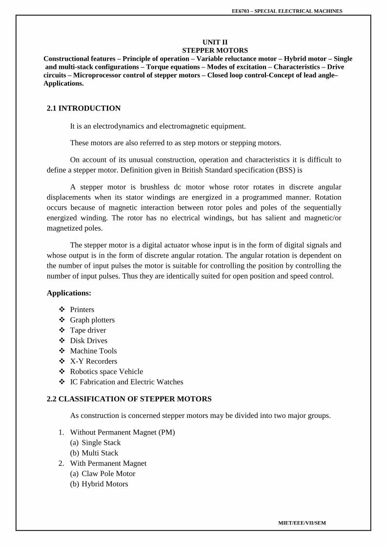
Next phase b is energized by turning on the semiconductor switch S2 and phase ‗a‘ isde –energized by turning off S1.Then the rotor poles 1 and 3 and 2 and 4 experience torquesin opposite direction. When the rotor and stator teeth are out of alignment in the excitedphase the magnetic reluctance is large. The torque experienced by 1 and 3 are in clockwisedirection and that of 2 and 4 is in counter clockwise direction. The latter is more than theformer. As a result the rotor makes an angular displacement of 30° in counterclockwisedirection so that B and B‘ and 2 and 4 in alignment. The phases are excited in sequence a, band c the rotor turns with a step of 30° in counter clockwise direction. The direction ofrotation can be reversed by reversing the switching sequence in which are energized and isindependent of the direction of currents through the phase winding.
In this mode two stator phases are excited simultaneously. When phases a and b areenergized together, the rotor experiences torque from both phases and comes to rest in a pointmid-way between the two adjacent full step position. If the phases b and c are excited, therotor occupies a position such that angle between AA‘ axis of stator and 1-3 axis of rotor isequal to 45°.To reverse the direction of rotation switching sequence is changed a and b,a andc etc. The main advantage of this type of operation is that torque developed by the steppermotor is more than that due to single phase ON mode of operation.
The truth table for mode II operation in counter clockwise and clockwise directions is givenin a tableTable
In this type of mode of operation on phase is ON for some duration and two phasesare ON during some other duration. The step angle can be reduced from 30° to 15° byexciting phase sequence a, a+b, b,b+c, c etc. The technique of shifting excitation from onephase to another from a to b with an intermediate step of a+b is known as half step and isused to realize smaller steps continuous half stepping produces smoother shaft rotation.
The truth table for mode III operation in counter and clockwise directions are given in thetableTable 2.5: Counter ClockwiseRotation (CCW) Table 2.6: Clockwise Rotation (CW)
A°AB°B°BC°C°CA°A°AB°B°BC°C°CA°
A°AB°B°
BC°C°
CA°A°
AB°B°
BC°C°
CA°
2.4 MICRO STEPPING CONTROL OF STEPPING MOTOR
Stepping motor is a digital actuator which moves in steps of θs in response to input pulses.such incremental motion results in the following limitations of the stepper motor
Limited resolution
As θs is the smallest angle through which the stepper motor can move, this has an effect onposition accuracy of incremental servo system employing stepper motors because the steppermotor cannot position the load to an accuracy finer than θs.
Mid frequency Resonance
A phenomenon in which the motor torque suddenly drops to a low value at certain pulsefrequencies as in fig
Fig 2.4 Mid frequency Resonance
EE6703 – SPECIAL ELECTRICAL MACHINES
MIET/EEE/VII/SEM
A new principal known as micro stepping control has been developed with a view ofovercoming the above limitation .It enables the stepping motor to move through a tiny microstep of size ∆ θs << θs full step angle is response to input pulses.
2.4.1 Principle of micro stepping
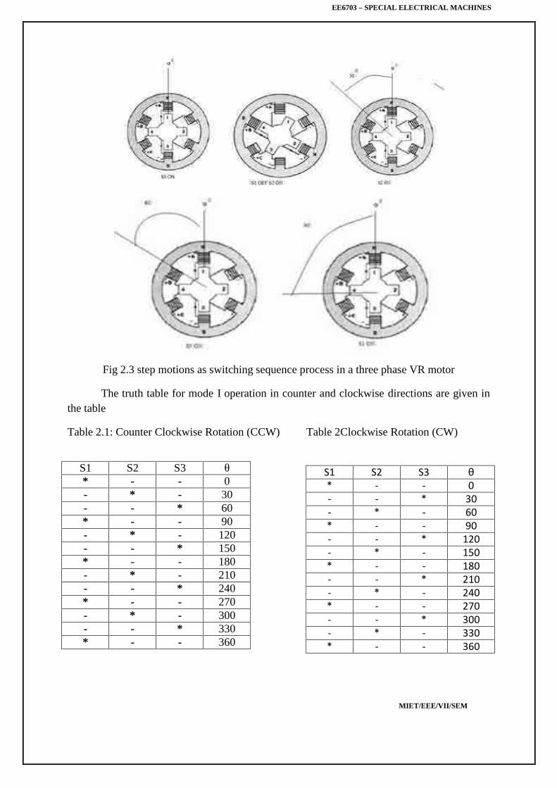
Assume a two phase stepper motor operating in ‗one phase ON‘ sequence. Assumealso that only B2 winding is On and carrying current IB2 = IR, the rated phase current. Allthe other winding are OFF. In this state the stator magnetic field is along the positive real axisas show in fig (a). Naturally the rotor will also as be in θ = 0° position.
When the next input pulse comes, B2 is switched OFF while A1 is switched ON.Inthis condition IA1= IR while all the phase current are zero. As a result the stator magneticfield rotates through 90® in counter clockwise direction as show in fig (a).
The rotor follows suit by rotating through 90° in the process of aligning itself withstator magnetic field. Thus with a conventional controller the stator magnetic field rotatesthrough 90° when a new input pulse is received causing the rotor to rotate full step.
However in micro stepping we want the stator magnetic field to rote through a smallangle θs << 90° in respect to input pulse. This is achieved by modulating the current throughB2 and A1 winding as show in fig (b) such that
IA1= IR sin θ
IB1= IR cos θ
Then the resulting stator magnetic field will be at an angle θ ° with respect to thepositive real axis. consequently the rotor will rotate through an angle θs << 90° .
This method of modulating current through stator winding so as to obtain rotation ofstator magnetic field through a small angle θ °
Fig 2.5 Principle of micro stepping
EE6703 – SPECIAL ELECTRICAL MACHINES
MIET/EEE/VII/SEM
2.5. MULTISTACK VARIABLE RELUCTANCE STEPPER MOTOR
These are used to obtain smaller step sizes, typically in the range of 2° to 15°. Although threestacks are common a multistack motor may employ as many as seven stacks. This type is alsoknown as the cascade type. A cutaway view of a three stack motor is shown in fig. 2.6.
Fig. 2.6: Construction of multi-stack VR motor.
A multistack (or m-stack) variable reluctance stepper motor can be considered to be made upof ‘m‘ identical single stack variable reluctance motors with their rotors mounted on a singleshaft. The stators and rotors have the same number of poles (or teeth) and therefore same pole(tooth) pitch. For a m0stack motor, the stator poles (or teeth) in all m stacks are aligned, butthe rotor poles (teeth) are displaced by 1/m of the pole pitch angle from one another. All thestator pole windings in a given stack are exited simultaneously and, therefore the statorwinding of each stack forms one phase. Thus the motor has the same number of phases asnumber of stacks.
Fig. 2.7: Cross-section of a 3-stack, VR stepper motor parallel to the shaft.
Figure 2.7 shows the cross section of a three stack (3-phase) motor parallel to the shaft. Ineach stack, stator and rotors have 12 poles (teeth). For a 12 pole rotor, pole pitch is 30° andtherefore, the rotor poles (teeth) are displaced from each other by 1/3rd of the pole pitch or
EE6703 – SPECIAL ELECTRICAL MACHINES
MIET/EEE/VII/SEM
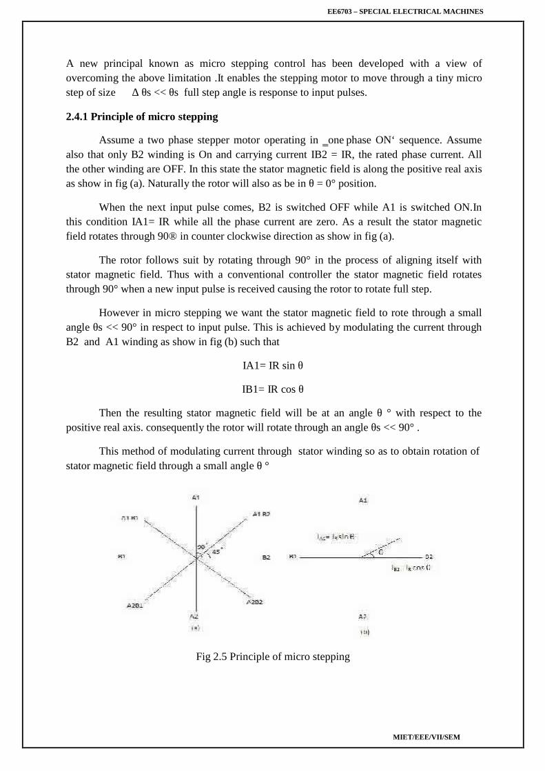
10°. The stator teeth in each stack are aligned. When the phase winding A is excited rotorteeth of stack A are aligned with the stator teeth as shown in fig. 2.8.When phase A is de-energized and phase B is excited the rotor teeth of stack B are alignedwith stator teeth. The new alignment is made by the rotor movement of 10° in theanticlockwise direction. Thus the motor moves one step (equal to ½ pole pitch) due to changeof excitation from stack A to stack B
Next phase B is de-energized and phase C is excited. The rotor moves by another step 1/3rdof pole pitch in the anticlockwise direction. Another change of excitation from stack C tostack A will once more align the stator and rotor teeth in stack A. however during this process(A → B → C → A) the rotor has moved one rotor tooth pitch.
Fig. 2.8: Position of stator & rotor teeth of 3 stack VR motor
Let Nr be the number of rotor teeth and ‗m‘ the number of stacks or phases, then
Tooth pitch Tp= 360/Nr ……………… (2.1)
Step Angle α= 360°/mNr ………………. (2.2)
2.6. Hybrid stepper motor
Principle of operation
Most widely used hybrid motor is the two phase type as shown in fig2.11. Thismodel has four poles and operates on one phase on excitation.
EE6703 – SPECIAL ELECTRICAL MACHINES
MIET/EEE/VII/SEM
Fig2.9cross-section of a two phase hybrid motor
The coil in pole 1 and that in pole 3 are connected in series consisting of phase A, andpole 2 and 4 are for phase B. Fig 2.12 shows the proce3ss of rotor journey as the windingcurrents are switched in one phase ON excitation.
Fig2.10 one-phase on operation of a two-phase hybrid motor.
The poles of phase A are excited the teeth of pole 1 attract some of the rotors northpoles, while the teeth of pole 3 align with rotor‘s south poles. Current is then switched tophase B, The rotor will travel a quarter tooth pitch so that tooth alignment takes place in 2and 4.
Next current is switched back to phase A but in opposite polarity to before, the rotorwill make another quarter tooth journey. The tooth alignment occurs in opposite magneticpolarity to state 1. When current is switched to phase B in opposite polarity (4) Occurs as aresult of quarter tooth pitch journey.
The structures of two phase motor considered in fig.2.11 will not produce force in asymmetrical manner with respect to the axis. The motor having 8 poles in the stator shown infig2.13 considered as the structure in which torque is generated at a symmetrical position onthe surface.
Fig2.11 Two-phase hybrid motor with 8 stator poles.
.7 CLAW TOOTH PM MOTOR
EE6703 – SPECIAL ELECTRICAL MACHINES
MIET/EEE/VII/SEM
This is another type of stepping motor. This is also known as can-stack Steppingmotor, as the stator of this motor consists of a sort of metal can. Teeth are punched out of acircular metal sheet and the circle is then drawn into a bell shape. The teeth are then drawninside to form claw teeth. A Stack of the stator is formed by joining two bell shaped casingsso that the teeth of both of them are intermeshed and the toroid coil is contained within them
This type of motor shown in fig 2.14 is usually of two stacks. Since the rotor hasmagnetic poles that are axially aligned and is common for both stator stacks, the stator toothpitches are misaligned by a quarter pitches between the two stacks.
Fig. 2.12 Cutaway diagram of a claw-tooth PM motor
The sequence of excitation is shown in fig. when phase A is excited, the rotor moves bythe tension of magnetic lines (state 1).state 2 is the equilibrium position with phase A excited.Next if current is switched to phase B , the rotor will be driven further in the same direction,because the stator teeth in stack B are misaligned by a quarter tooth pitch to the left
Fig. 2.13 Current waveform supplied to a claw-tooth PM motor
with respect to the teeth in stack A. State 3 shows the result due to this excitation. To advancethe rotor further to the left and place in the next state (4), phase B is de-energized and phaseA is excited. Next, current will be switched to phase B.
EE6703 – SPECIAL ELECTRICAL MACHINES
MIET/EEE/VII/SEM
The claw tooth motor has low manufacturing cost through it cannot realize a very smallstep angle.
2.8. SINGLE PHASE STEPPING MOTOR
These are motors which are designed to be operated from single phase supply. Theyare widely use in watches and clocks, timers and counters. Present single phase steppingmotors use one or more (two) permanent magnets, because permanent magnets are quitenecessary to raise the ratio of torque to input power in a miniature motor.
The two requirements of single phase stepping motor are
To detent the motor at a particular position when the coil is not excited.
To rotate the motor at desired direction by switching the magnetic polarity of only one coil.
2.8.1 CONSTRUCTION
It is a permanent magnet type stepper motor with two poles. Rotor is a circular type ofpermanent magnet as shown in figure 2.27.ststor is made of silicon steel stampings with twosalient poles. Stator carries a coil which is connected to a pulsed supply. The air gap isspecially designed so that specific reluctance at different radial axes are different. Minimumvalues occur at one tip of the poles. Under normal conditions the rotor occupies any one ofthe decent position shown in fig 2.28(a0 or as in (b) to minimum reluctance position. twopositions shown in figures 2.28(a) & (b) are the detent positions of the rotor of the steppermotor.
Fig. 2.14 A single-phase stepping motor
EE6703 – SPECIAL ELECTRICAL MACHINES
MIET/EEE/VII/SEM
Fig. 2.15 Detent positions and coil polarity to rotate motor.
2.8.2. PRINCIPLE OF OPERATION
When the coil is given an electric positive pulse, pole A in position 1 as shown infigure. 2.28(a) it experiences a torque in clockwise direction and finally attains a steady stateas in fig 2.28(b).then pulse given to the coil is zero. After a lapse of a second, from the startof the pulse, a negative pulse is given to the coil which makes the pole A as south and pole Bas north. Rotor experiences another torque in figure 2.28(a).by repeating the cycle the rotorrotates continuously in step .it is not possible to develop torque in counter clockwise directionby altering pulses.
2.9. THEORY OF TORQUE PREDICTION
According to Faradays laws of electromagnetic induction
Flux linkages λ=Nυ ……….. (2.3)
λ=Li ……..… (2.4)
Flux linkages can be varied by
Varying flux υ
Varying the current ‗i‘ of an electromagnet (i.e) equivalent of varying the mmf
Varying the reluctance L =
By varying reluctance
mmf = Nυ …………….. (2.5)
Reluctance = ………….(2.6)
Flux = ……….… (2.7)
Flux linkages λ = = ………. (2.8)
Inductance L = ………. (2.9)
L = ………….. (2.10)
L = ………….(2.11)
If the reluctance of magnetic circuit can be varied, inductance L and the flux linkages λ canalso be varied.
EE6703 – SPECIAL ELECTRICAL MACHINES
MIET/EEE/VII/SEM
Consider a magnetic circuit as shown in fig. 2.29.
Fig. 2.16 Magnetic circuit
The stator consists magnetic core with two pole arrangement. Stator core carries acoil. Rotor is also made up of ferrous material. The motor core is similar to a salient polemachine. Let the angle between the axis of stator pole and rotor pole be θ. let the angulardisplacement be illustrated using fig. 2.29 (a, b and c).
Case 1: θ = 0
As shown in fig. 2.29 (a) the air gap between the stator and rotor is very very small.Thereby the reluctance of the magnetic path is least. Due to minimum reluctance, theinductance of the circuit is minimum. Let it be
Case 2 : θ =
As shown in fig. 2.29(b) in this only a portion of rotor poles cover the stator poles.Therefore reluctance of the magnetic path is more than that of case 1.due to which theinductance becomes less than .
Case 3: θ =
As shown in fig. 2.29(c) the air gap between the stator poles has maximum value.Thereby reluctance has a value yielding minimum inductance. Let it be .
Variation in inductance with respect to the angle between the stator and rotor poles isshown in fig. 2.30.
Fig. 2.17 Variation in induction w.r to θ.
EE6703 – SPECIAL ELECTRICAL MACHINES
MIET/EEE/VII/SEM
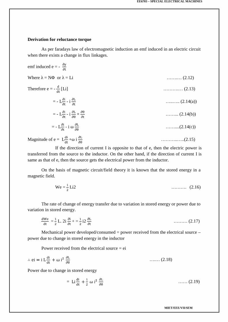
Derivation for reluctance torque
As per faradays law of electromagnetic induction an emf induced in an electric circuitwhen there exists a change in flux linkages.
emf induced e = -
Where λ = NΦ or λ = Li …….… (2.12)
Therefore e = - [Li] ……….… (2.13)
= - L - i …..….. (2.14(a))
= - L - i × ……... (2.14(b))
= - L - i ω ……....(2.14(c))
Magnitude of e = L +ω i ………..…..(2.15)
If the direction of current I is opposite to that of e, then the electric power istransferred from the source to the inductor. On the other hand, if the direction of current I issame as that of e, then the source gets the electrical power from the inductor.
On the basis of magnetic circuit/field theory it is known that the stored energy in amagnetic field.
We = Li2 ………. (2.16)
The rate of change of energy transfer due to variation in stored energy or power due tovariation in stored energy.
= L. 2i + = i2 ……… (2.17)
Mechanical power developed/consumed = power received from the electrical source –power due to change in stored energy in the inductor
Power received from the electrical source = ei
….… (2.18)
Power due to change in stored energy
= …… (2.19)
EE6703 – SPECIAL ELECTRICAL MACHINES
MIET/EEE/VII/SEM
Mechanical power developed
= + …… (2.20)
Mechanical power developed
Pm = ωi2 …… (2.21)
Pm = …… (2.22)
Pm = ωT …… (2.23)
Where ω =
Therefore reluctance torque T = …… (2.24)
Reluctance torque T = …… (2.25)
Note:
* Torque corresponds to monitoring when is +ve.
* Torque corresponds to generating when is -ve.
* Torque is proportional to i2 : Therefore it does not depend upon the direction of thecurrent.
2.10 TERMINOLOGIES USED IN STEPPER MOTOR
1. Step motor
2. Resolution
3. Stepping rate
4. Hold position
5. Detent position
6. Stepping error
7. Position Error
1. Step angle (θs or β)
EE6703 – SPECIAL ELECTRICAL MACHINES
MIET/EEE/VII/SEM
It is the angular displacement of rotor of a stepper motor for every pulse of excitationgiven to the stator winding of the motor. it is determined by the number of teeth on the rotorand stator, as well as the number of steps in the energisation sequence. It is given by
Θs = β =
Where
m = Number of phases (m and q)
Nr- number of teeth on rotor.
Also, Θs=((Ns~Nr)/(Ns.Nr))*360
2. Resolution
It is the number of steps per revolution. It is denoted as S or Z. it is given by
Z=360/(Θs)
For variable reluctance motor Z=(q Nr) or (m Nr)
For PM motor and hybrid motor Z=2q Nr
Also , Z=(Ns.Nr)/(Ns~Nr)
Where Ns-number of teeth/poles on stator.
3. Stepping Rate
The number of steps per second is known as stepping rate or stepping frequency.
4. Hold Position
It corresponds to the rest position when the stepper motor is excited or energized(thiscorresponds to align position of VR motor)
5. Detent Position
It corresponds to rest position of the motor when it is not excited.
6. Stepping Error
Actual step angle is slightly different from the theoretical step angle. This is mainlydue to tolerances in the manufacture of stepper motor and the properties of the magnetic andother materials used.
The error in the step angle is expressed as a percentage of the theoretical step angle.
Percentage error is restricted to ± 5%.In some cases it is restricted to ±2%. Thecumulative error between the actual angular displacement and theoretical angulardisplacement is expressed as a percentage of theoretical angular displacement. It is usuallyconsidered for one complete cycle.
7. Positional Error
The maximum range of cumulative percentage of error taken over a complete rotationof stepper motor is referred to as positional accuracy as shown in fig below.
Fig. 2.18 Positional Accuracy
2.11. CHARACTERISTICS OF STEPPER MOTOR
Stepper motor characteristics are divided into two groups
Static characteristics Dynamic characteristics
2.11.1. Static characteristics
It is divided into two charteristics.
(i)Torque Angle curve
(ii)Torque current curve
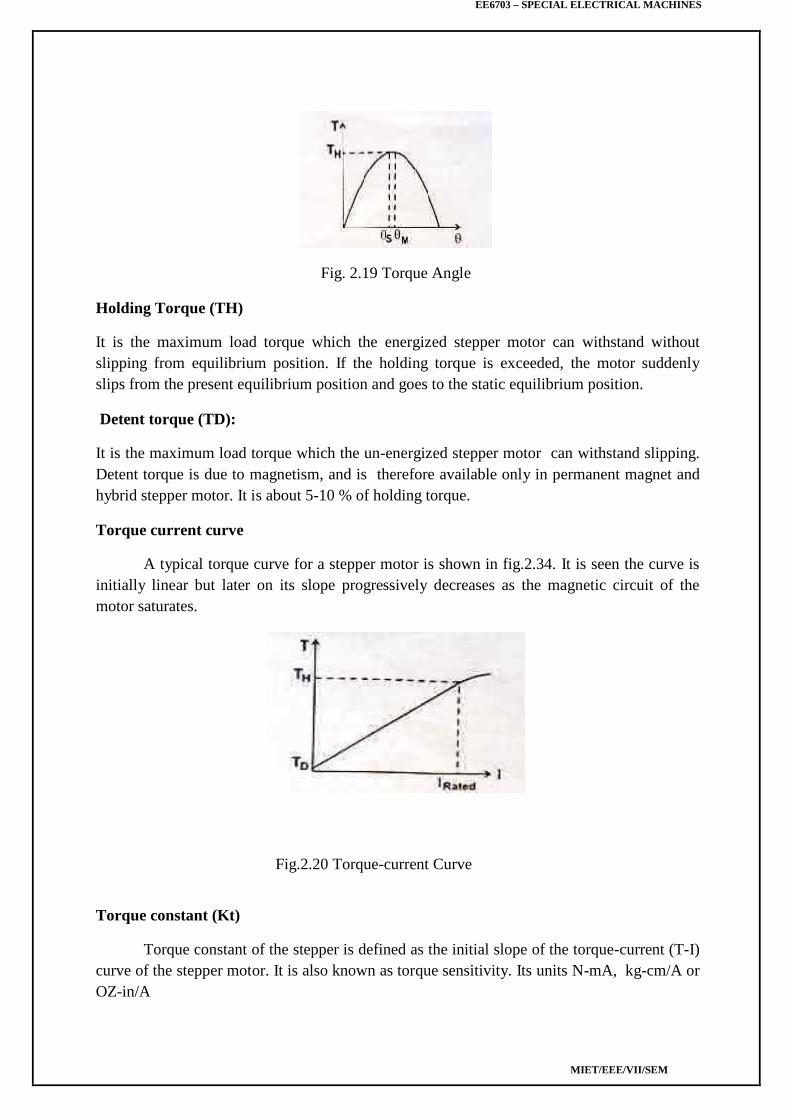
(i)Torque-Angle curve
Torque angle curve of a step motor is shown in fig.2.32. it is seen that the Torqueincreases almost sinusoid ally, with angle Θ from equilibrium.
EE6703 – SPECIAL ELECTRICAL MACHINES
MIET/EEE/VII/SEM
Fig. 2.19 Torque Angle
Holding Torque (TH)
It is the maximum load torque which the energized stepper motor can withstand withoutslipping from equilibrium position. If the holding torque is exceeded, the motor suddenlyslips from the present equilibrium position and goes to the static equilibrium position.
Detent torque (TD):
It is the maximum load torque which the un-energized stepper motor can withstand slipping.Detent torque is due to magnetism, and is therefore available only in permanent magnet andhybrid stepper motor. It is about 5-10 % of holding torque.
Torque current curve
A typical torque curve for a stepper motor is shown in fig.2.34. It is seen the curve isinitially linear but later on its slope progressively decreases as the magnetic circuit of themotor saturates.
Fig.2.20 Torque-current Curve
Torque constant (Kt)
Torque constant of the stepper is defined as the initial slope of the torque-current (T-I)curve of the stepper motor. It is also known as torque sensitivity. Its units N-mA, kg-cm/A orOZ-in/A
EE6703 – SPECIAL ELECTRICAL MACHINES
MIET/EEE/VII/SEM
2.11.2. Dynamic characteristics
A stepper motor is said to be operated in synchronism when there exist strictly one toone correspondence between number of pulses applied and the number of steps throughwhich the motor has actually moved. There are two modes of operation.
Start-Stop mode
Also called as pull in curve or single stepping mode.
Slewing mode
In start –stop mode the stepper motor always operate in synchronism and themotor can be started and stopped without using synchronism. In slewing mode the motor willbe in synchronism, but it cannot be started or stopped without losing synchronism. To operatethe motor in slewing mode first the motor is to be started in start stop mode and then toslewing mode. Similarly to stop the motor operating in slewing mode, first the motor is to bebrought to the start stop mode and then stop.
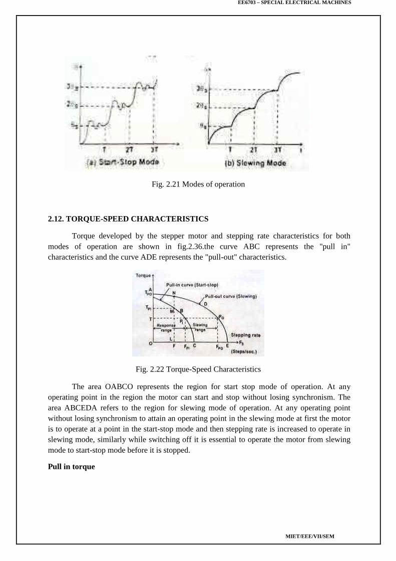
Start Stop mode
Start stop mode of operation of stepper motor is shown in fig.2.35 (a).In this secondpulse is given to the stepper motor only after the rotor attained a steady or rest position due tofirst pulse. The region of start-stop mode of operation depends on the operation depends onthe torque developed and the stepping rate or stepping frequency of stepper motor.
pulse is given to the stepper motor only after the rotor attained a steady or rest position due tofirst pulse. The region of start-stop mode of operation depends on the operation depends onthe torque developed and the stepping rate or stepping frequency of stepper motor.
EE6703 – SPECIAL ELECTRICAL MACHINES
MIET/EEE/VII/SEM
Fig. 2.21 Modes of operation
2.12. TORQUE-SPEED CHARACTERISTICS
Torque developed by the stepper motor and stepping rate characteristics for bothmodes of operation are shown in fig.2.36.the curve ABC represents the "pull in"characteristics and the curve ADE represents the "pull-out" characteristics.
Fig. 2.22 Torque-Speed Characteristics
The area OABCO represents the region for start stop mode of operation. At anyoperating point in the region the motor can start and stop without losing synchronism. Thearea ABCEDA refers to the region for slewing mode of operation. At any operating pointwithout losing synchronism to attain an operating point in the slewing mode at first the motoris to operate at a point in the start-stop mode and then stepping rate is increased to operate inslewing mode, similarly while switching off it is essential to operate the motor from slewingmode to start-stop mode before it is stopped.
Pull in torque
EE6703 – SPECIAL ELECTRICAL MACHINES
MIET/EEE/VII/SEM
It is the maximum torque developed by the stepper motor for a given stepping rate in thestart-stop mode of operation without losing synchronism. In the fig.2.36 LM represents thepull in torque (i.e)TPI corresponding to the stepping rate F (i.e.) OL.
Pull out torque
It is the maximum torque developed by the stepper motor for a given stepping rate inthe slewing mode without losing synchronism. In fig.2.36 LN represents the pull in torque(i.e.) TPO corresponding to F (i.e.) OL.
Pull in range
It is the maximum stepping rate at which the stepper motor can operate in start-stopmode developing a specific torque (without losing synchronism).In fig. 2.36 PIT representspull in range for a torque of T (i.e.) OP. This range is also known as response range ofstepping rate for the given torque T.
Pull out range
It is the maximum stepping rate at which the stepper motor can operate in slewingmode developing a specified torque without losing synchronism. In fig.2.36 PIPO representsthe pull out range for a torque of T. The range PIPO is known slewing range.
Pull in rate (FPI)
It is the maximum stepping rate at which the stepper motor will start or stop withoutlosing synchronism against a given load torque T.
Pull out rate (FPO)
It is the maximum stepping rate at which the stepper motor will slew, without missingsteps, against load torque T.
Synchronism
This term means one to one correspondence between the number of pulses applied tothe stepper motor and the number of steps through which the motor has actually moved.
Mid frequency resonance
The phenomenon at which the motor torque drops to a low value at certain input pulsefrequencies.
2.13 FIGURES OF MERIT (FM'S)
Figures of merit (FM'S) are performance indices which give quantitative informationon certain aspects of performance and design of actuators such as stepper motors. DC or ACservomotorsetc.
EE6703 – SPECIAL ELECTRICAL MACHINES
MIET/EEE/VII/SEM
1. Electrical Time constant (Te)
Te=Lm/Rm ……….. (2.26)
where Lm-Inductance of motor winding
Rm-resistance of motor.
Te governs the rate at which current rises when the motor winding is turned on.It alsodetermines how quickly the current decays when the winding is turned off.
In motion control, the speed of response is of importance. Hence electrical timeconstant Te must be minimized.
Te dependent upon inductance and resistance of the motor winding. Inductance isdetermined by magnetic circuit. (i.e.) magnet iron volume as well as volume of copper usedin the motor design. Once these have been designed, neither reducing conductor size norincreasing the number of turns will reduce Te. Otherwise magnetic circuit itself has to beredesigned.
2. Motor time constant (Tm)
Tm=J/(Ke.KtRm)=JRm/Ke ………… (2.27)
J-moment of inertia of motor (kg-m2)
Rm-resistance of the motor winding (Ω)
Ke-back emf constant(volt s/ rad)
Kt- torque constant (Nm/A)
Motor back emf and torque constants are determined by magnetic circuit and phasewinding design. Winding resistance also from winding design. Moment of inertia isdetermined by mechanical design.
In this way motor time constant Tm combines all the three aspects of motor designviz, magnetic circuit, electrical circuit and mechanical design. Achieving a low Tm requiresexcellence in motor design. As a thumb rule the ratio of Te/Tm 0.1
Initial Acceleration (a0):
A0=T/J(rad/S2)
Where T-rated torque (N-M)
J-moment of inertia(kg-m2)
EE6703 – SPECIAL ELECTRICAL MACHINES
MIET/EEE/VII/SEM
a0 gives a quantitative idea of how fast the motor accelerates to its final velocity orposition. Maximization of a0 calls for good magnetic circuit design to produce high torque inconjunction with good mechanical design to minimize rotor inertia. The moment of inertia ofthe load coupled to motor also determines a0.Motor Constant (km)
km=T/√ ω
where T- rated motor torque
ω -rated power(w) of the motor
km=√Kt Ke/Rm
This shows that maximizing km causes minimizing R, maximizing Ke and Kt. MaximizingKe and Kt. Call for optimization of magnetic circuit design, decreasing electrical timeconstant Te which is undesirable. A trade off between electrical and magnetic circuit designis necessary to achieve a good km.
Power rate (dP/dt):
Power rate is (dP/dt)=(d/dt)(T.(dϴ /dt))= T.(d2ϴ /dt2)=T.(T/J)=(T2/J) …..(2.28)
Now T=Kt I so
2.14 DRIVE SYSTEM AND CONTROL CIRCUITRY FOR STEPPER MOTOR
2.14.1 DRIVE SYSTEM
The stepper motor is a digital device that needs binary (digital) signals for itsoperation .Depending on the stator construction two or more phases have to be sequentiallyswitched using a master clock pulse input. The clock frequency determines the stepping rate,and hence the speed of the motor. The control circuit generating the sequence is called atranslator or logic sequencer.
Fig. 2.23 Block Diagram of the drive system of a stepping motor.
The fig 2.38 shows the block diagram of a typical control circuit for a steppermotor. It consists of a logic sequencer, power driver and essential protective circuits forcurrent and voltage limiting. This control circuit enables the stepper motor to be run at adesired speed in either direction. The power driver is essentially a current amplifier, since the
EE6703 – SPECIAL ELECTRICAL MACHINES
MIET/EEE/VII/SEM
sequence generator can supply only logic but not any power. The controller structure for VRor hybrid types of stepper motor
Fig. 2.24 Block diagram of a typical step motor control
2.14.2 LOGIC SEQUENCER
The logic sequencer is a logic circuit which control the excitation of thewinding sequentially, responding to step command pulses. A logic sequencer is usuallycomposed of a shifter register and logic gates such as NANDs, NORs etc. But one canassemble a logic sequencer for a particular purpose by a proper combination of JK flip flop,IC chips and logic gate chips.
Two simple types of sequencer build with only two JK-FFs are shown in fig2.39 for unidirectional case. Truth tables for logic sequencer also given for both thedirections.
EE6703 – SPECIAL ELECTRICAL MACHINES
MIET/EEE/VII/SEM
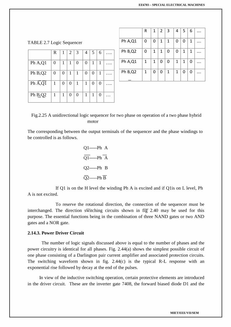
R 1 2 3 4 5 6 ….
Ph A,Q1 0 0 1 1 0 0 1 ….
Ph B,Q2 0 1 1 0 0 1 1 ….
Ph A,Q1 1 1 0 0 1 1 0 ….
Ph B,Q2 1 0 0 1 1 0 0 ….
TABLE 2.7 Logic Sequencer
R 1 2 3 4 5 6 ….
Ph A,Q1 0 1 1 0 0 1 1 ….
Ph B,Q2 0 0 1 1 0 0 1 ….
Ph A,Q1 1 0 0 1 1 0 0 ….
Ph B,Q2 1 1 0 0 1 1 0 …
Fig.2.25 A unidirectional logic sequencer for two phase on operation of a two phase hybridmotor
The corresponding between the output terminals of the sequencer and the phase windings tobe controlled is as follows.
Q1-----Ph A
Q1-----Ph A
Q2-----Ph B
Q2-----Ph B
If Q1 is on the H level the winding Ph A is excited and if Q1is on L level, PhA is not excited.
To reserve the rotational direction, the connection of the sequencer must beinterchanged. The direction switching circuits shown in fig 2.40 may be used for thispurpose. The essential functions being in the combination of three NAND gates or two ANDgates and a NOR gate.
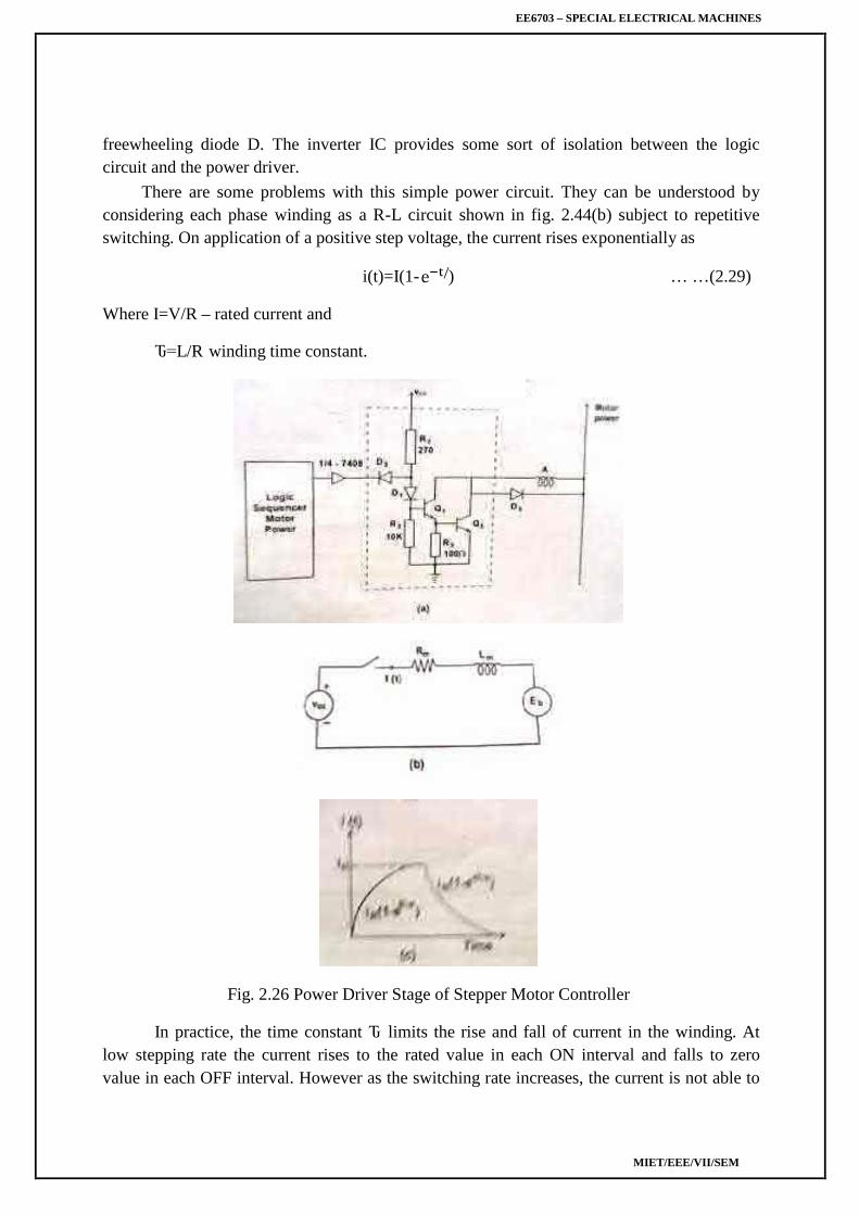
2.14.3. Power Driver Circuit
The number of logic signals discussed above is equal to the number of phases and thepower circuitry is identical for all phases. Fig. 2.44(a) shows the simplest possible circuit ofone phase consisting of a Darlington pair current amplifier and associated protection circuits.The switching waveform shown in fig. 2.44(c) is the typical R-L response with anexponential rise followed by decay at the end of the pulses.
In view of the inductive switching operation, certain protective elements are introducedin the driver circuit. These are the inverter gate 7408, the forward biased diode D1 and the
EE6703 – SPECIAL ELECTRICAL MACHINES
MIET/EEE/VII/SEM
freewheeling diode D. The inverter IC provides some sort of isolation between the logiccircuit and the power driver.
There are some problems with this simple power circuit. They can be understood byconsidering each phase winding as a R-L circuit shown in fig. 2.44(b) subject to repetitiveswitching. On application of a positive step voltage, the current rises exponentially as
i(t)=I(1- ) … …(2.29)
Where I=V/R – rated current and
Ԏ=L/R winding time constant.
Fig. 2.26 Power Driver Stage of Stepper Motor Controller
In practice, the time constant Ԏ limits the rise and fall of current in the winding. Atlow stepping rate the current rises to the rated value in each ON interval and falls to zerovalue in each OFF interval. However as the switching rate increases, the current is not able to
EE6703 – SPECIAL ELECTRICAL MACHINES
MIET/EEE/VII/SEM
rise to the steady state, nor fall down to zero value with in the on/off time intervals set by thepulse waveform. This in effect, smoothens the winding current reducing the swing as shownin fig. 2.45. As a result the torque developed by the motor gets reduced considerably and forhigher frequencies, the motor just ‗vibrates‘ or oscillates within one step of the currentmechanical position.
Fig. 2.27 Effect of increasing Stepping Rate on Current Swing
In order to overcome these problems and to make improvement of current build up severalmethods of drive circuits have been developed.
For example when a transistor is turned on to9 excite a phase, the power supply mustovercome effect of winding inductances has tendency to oppose the current built up. Asswitching frequency increases the position that the buildup time takes up within the switchingcycle becomes large and it results in decreased torque and slow response.
2.14.4 Improvement of current buildup/special driver circuit
(a) Resistance drive (L/R drive)
Here the initial slope of the current waveform is made higher by adding external resistance ineach winding and applying a higher voltage proportionally. While this increases the rate ofrise of the current, the maximum value remains unchanged as shown in fig. 2.46.
Fig. 2.28 L/R drive
EE6703 – SPECIAL ELECTRICAL MACHINES
MIET/EEE/VII/SEM
The circuit time constant is now reduced and the motor is able to develop normal torque evenat high frequencies. The disadvantage of this method is
Flow of current through external resistance causes R losses and heating. This denoteswastage of power as far as the motor is concerned.
In order to reach the same steady state current as before, the voltage required
To be applied is much higher than before. Hence this approach is suitable for smallinstrument stepper motor with current ratings around 100 mA, and heating is not a majorproblem.
(b) Dual voltage driver (or) Bi-level driver
To reduce the power dissipation in the driver and increase the performance of astepping motor, a dual-voltage driver is used. The scheme for one phase is shown in fig. 2.47.
When a step command pulse is given to the sequencer, a high level signal will be putout from one of the output terminal to excite a phase winding. On this signal both 1 and
2 are turned on, and the higher voltage will be applied to the winding. The diode isnow reverse biased to isolate the lower voltage supply. The current build up quickly due tothe higher voltage . The time constant of the monostable multivibrator is selected so thattransistor 1 is turned off when the winding current exceeds the rated current by a little.After the higher
Fig. 2.29 Improvement of current buildup by dual voltage drive
Voltage source is cut off the diode is forward biased and the winding current is supplied fromthe lower voltage supply. A typical current wave form is shown in fig. 2.48.
EE6703 – SPECIAL ELECTRICAL MACHINES
MIET/EEE/VII/SEM
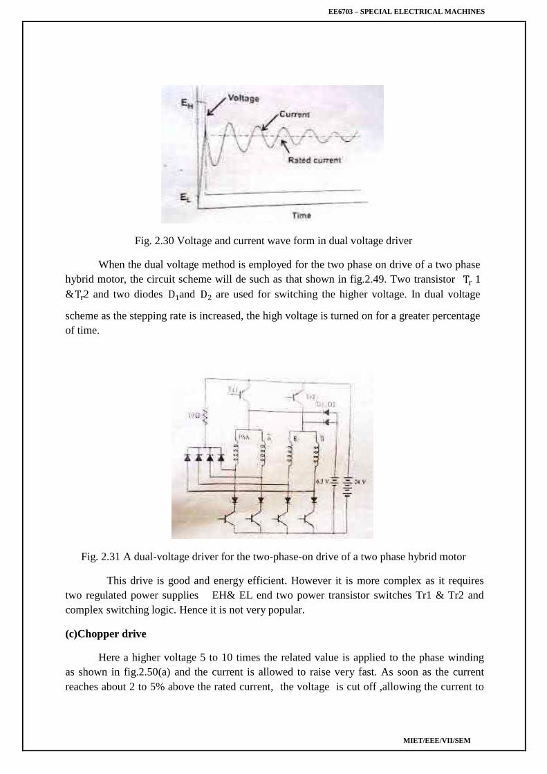
Fig. 2.30 Voltage and current wave form in dual voltage driver
When the dual voltage method is employed for the two phase on drive of a two phasehybrid motor, the circuit scheme will de such as that shown in fig.2.49. Two transistor 1& 2 and two diodes and are used for switching the higher voltage. In dual voltage
scheme as the stepping rate is increased, the high voltage is turned on for a greater percentageof time.
Fig. 2.31 A dual-voltage driver for the two-phase-on drive of a two phase hybrid motor
This drive is good and energy efficient. However it is more complex as it requirestwo regulated power supplies EH& EL end two power transistor switches Tr1 & Tr2 andcomplex switching logic. Hence it is not very popular.
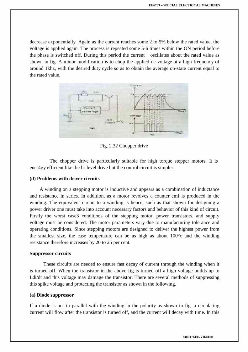
(c)Chopper drive
Here a higher voltage 5 to 10 times the related value is applied to the phase windingas shown in fig.2.50(a) and the current is allowed to raise very fast. As soon as the currentreaches about 2 to 5% above the rated current, the voltage is cut off ,allowing the current to
EE6703 – SPECIAL ELECTRICAL MACHINES
MIET/EEE/VII/SEM
decrease exponentially. Again as the current reaches some 2 to 5% below the rated value, thevoltage is applied again. The process is repeated some 5-6 times within the ON period beforethe phase is switched off. During this period the current oscillates about the rated value asshown in fig. A minor modification is to chop the applied dc voltage at a high frequency ofaround 1khz, with the desired duty cycle so as to obtain the average on-state current equal tothe rated value.
Fig. 2.32 Chopper drive
The chopper drive is particularly suitable for high torque stepper motors. It isener4gy efficient like the bi-level drive but the control circuit is simpler.
(d) Problems with driver circuits
A winding on a stepping motor is inductive and appears as a combination of inductanceand resistance in series. In addition, as a motor revolves a counter emf is produced in thewinding. The equivalent circuit to a winding is hence, such as that shown for designing apower driver one must take into account necessary factors and behavior of this kind of circuit.Firstly the worst case3 conditions of the stepping motor, power transistors, and supplyvoltage must be considered. The motor parameters vary due to manufacturing tolerance andoperating conditions. Since stepping motors are designed to deliver the highest power fromthe smallest size, the case temperature can be as high as about 100°c and the windingresistance therefore increases by 20 to 25 per cent.
Suppressor circuits
These circuits are needed to ensure fast decay of current through the winding when itis turned off. When the transistor in the above fig is turned off a high voltage builds up toLdi/dt and this voltage may damage the transistor. There are several methods of suppressingthis spike voltage and protecting the transistor as shown in the following.
(a) Diode suppressor
If a diode is put in parallel with the winding in the polarity as shown in fig. a circulatingcurrent will flow after the transistor is turned off, and the current will decay with time. In this
EE6703 – SPECIAL ELECTRICAL MACHINES
MIET/EEE/VII/SEM
scheme, no big change in current appears at turn off, and the collector potential is the supplypotential E plus the forward potential of the diode. This method is very simple but adrawback is that the circulating current lasts for a considerable length of time and it producesa braking torque.
Fig. 2.33 Diode suppressor
(b)Diode-Resistor suppressor
A resistor is connected in series with the diode as shown in fig to damp quickly thecirculating current. The voltage VCE applied to the collector at turn-off in this scheme is
VCE=E+IRS+VD
Where E= supply potential
I= Current before turning off
Rs-resistance of suppressor resistor
VD-forward potential of diode
Fig. 2.34 Diode-resistor suppressor
EE6703 – SPECIAL ELECTRICAL MACHINES
MIET/EEE/VII/SEM
A high resistance RS is required to achieve a quick current decay, but this also results ina higher collector potential VCE, thus a transistor with a high maximum voltage rating isnecessary.
(a) Zener diode suppressor
In this zener diode are often used to connect in series with the ordinary diode asshown in fig. Compared with preceding two cases zener diode which provides negative biascauses the current to decay more quickly after turn off. In addition to this, it is a merit of thismethod that the potential applied to the collector is the supply potential plus the zenerpotential, independent of the current. This makes the determination of the rating of themaximum collector potential easy. However zeners are signal diodes, rather than powerdiodes. Their power dissipation is limited to 5w. Consequently, this suppressor can be usedfor very small instrument stepper motors of typical size 8 to 11.
Comparison of effects of various suppressor schemes of various suppressor schemes
Fig. 2.35 Zener diode Fig. 2.36 Comparison of effects
(d)Condenser suppressor
This scheme is often employed for bifilar-wound hybrid motor. An explanation isgiven for the given for the circuit shown in fig:
EE6703 – SPECIAL ELECTRICAL MACHINES
MIET/EEE/VII/SEM
Fig. 2.37 Condenser suppressor
condensers serve two fold purposes.
.
These
1. When a transistor is turned off, the condenser connected to it via a diode absorbs thedecaying current from the winding to protect the transistor.
Let us see the situation just after the Tr 1 is turned off in the one phase
are wound in the bifilar fashion, a transient current will circulate in loop. If Tr 3is turned on when the transient current becomes zero and the charge stored in the condenserbecomes maximum, a positive current can easily flow through phase A winding. By thisresonance mechanism, currents are used efficiently in this scheme. This feature remains inthe two phase on mode too. The condenser suppressor is suited to drives in which steppingrate is limited in a narrow range.
2 .Another utility of condensers is as an electrical damper, a method of damping rotoroscillations is to provide a mechanism to convert kinetic energy to joule heating. If a rotorhaving a permanent magnet oscillates, an alternating emf is generated in the winding.However if a current path is not provided or a high resistance is connected, no current will becaused by this emf. When the condenser is connected between phases an oscillatory currentwill flow in the closed loop and joule heat is generated in the windings, which means that thecondenser works as an electrical damper.
2.15. LINEAR AND NON LINEAR ANALYSIS
The linear and nonlinear analysis of the motor performance with respect to the torqueproduced by the rotor of the motor is explained.
Let
Tm be the motor torque produced by the rotor in Nm
EE6703 – SPECIAL ELECTRICAL MACHINES
MIET/EEE/VII/SEM
J be the inertia of the rotor and load combination in kgm2
ω be the angular velocity of the rotor
D be the damping coefficient or viscous frictional coefficient
Tf be the frictional load torque independent of the speed
Θs be the step angle in radians
F be the stepping rate in steps/sec or pps
Frictional load torque Tf = K θ
According to rotor dynamics
Tm=―J*dω/dt+Dω+Tf ………….. (2.30)
Also θs=θ=ωt=step angle
ω=θs/t=f θs …………..(2.31)
where f=1/t ………….(2.32)
By putting ω=f θs
Tm=J *d/dt(f θs )+D(f θs )+Tf …………..(2.33)
θs=360/mNr is fixed for a particular type of motor
S o θs can be considered as constant
Therefore Tm=J θs* d/dt(f)+D θs(f)+Tf ………….(2.34)
In equation 2.47 if viscous friction constant is neglected the equation will be a linearequation, the corresponding acceleration will be nonlinear and the equation will be nonlinearwhich given rise to nonlinear analysis.
Linear acceleration on linear analysis
If the damping coefficient is neglected D=0
The expression for motor torque becomes
Tm=―J*dω/dt+Tf ………………(2.35)
Tm-Tf= J*dω/dt
(Tm-Tf)/J= dω/dt
dω=((Tm-Tf)/J)dt ……………….. (2.36)
EE6703 – SPECIAL ELECTRICAL MACHINES
MIET/EEE/VII/SEM
Integrating
ω=((Tm-Tf)/J)dt+ω1 ……………….. (2.37)
Where
ω1=Integration constant
Mathematically ω1 is the constant of integration but it indicates the initial angular velocityof the motor before the occurrence of acceleration.
Therefore ω=θs f and ω1= θs f1
Substituting ω and ω1 in equation 2.50
((Tm-Tf)/J)t+ θs f1= θsf ………………..(2.38)
Dividing throughout by θs we get
((Tm-Tf)/J θs)t+ f1=f
Therefore stepping rate f=((Tm-Tf)/J θs)t+ f1 ……………(2.39)
And Tf = K θ
Figure 2.38 shows the linear acceleration from ω1 to ω2
Nonlinear (exponential) acceleration on Nonlinear analysis
Considering the torque produced by the motor
Tm=jθs df/dt +Dθsf+Tf …….(2.40)
(Tm-Tf)= jθs df/dt +Dθsf
Dividing throughout by jθs We get
(df/dt)+(D/J)f-(Tm-Tf /j θs )=0
(or) (df/dt)+(D/J)f=(Tm-Tf /j θs ) …. (2.41)
The above eqn. 2.54 is of the form
(dy/dx)+py=Q Which have the solution of
EE6703 – SPECIAL ELECTRICAL MACHINES
MIET/EEE/VII/SEM
ye∫pdx =∫Q e∫pdx+C …..………….(2.42 )
Here y=f; x=t; p=(D/j) and Q=(Tm-Tf)/jθs =constant
To find C substituting initial condition at t=0; f=f(0)=f1f1e0==(Tm-Tf)/jθs(1/(D/J))+C …………..…..(2.46)
f1===(Tm-Tf)/Jθs(J/D))+C…………..…...(2.47)
f1=(Tm-Tf)/Dθs+C………….…..(2.48)
C= f1-(Tm-Tf)/Dθs .……………...(2.49)
Substituting eqn. (2.62) in eqn. (2.58)
f e(D/J)t=(Tm-Tf)/Jθs(J/D)e(D/J)t+( f1-(Tm-Tf)/Dθs) …………….….(2.50)
f e(D/J)t=(Tm-Tf)/Dθs e(D/J)t+( f1-(Tm-Tf)/Dθs) ………..……( 2.51)
Dividing throughout by e(D/J)t we get
F=Tm-Tf/Dθs +(f1-Tm-Tf/Dθs)e-D/j t ……………(2.52)
Stepping frequency f= Tm-Tf/Dθs +(f1-Tm-Tf/Dθs)e-D/j t
The above equation is a nonlinear exponential equation which gives rise to nonlinearacceleration of the rotor of the motor.
2.16 APPLICATION OF STEPPER MOTOR:
groups.The main application of stepper motor may be divided into the following
EE6703 – SPECIAL ELECTRICAL MACHINES
MIET/EEE/VII/SEM
1. Instrumentation applications.
2. Computer peripherals & Office equipment‘s.
3. Numerical control of machine tools and robotics.
4. Applications in semiconductor technology.
5. Space vehicles and satellites.
6. Electro medical and
7. Miscellaneous applications.
1. Instrumentation application:
This involve low torque applications such as
Quartz watches.
Synchronized clocks.
Camera shutter operations.
2. Stepper motor application in computer peripherals:
This involve medium torque, high performance and high volume application suchas
Dot matrix and line printers.
Graph plotters.
Floppy disk drives
Digital X-Y plotters.
Magnetic tape drives.
Paper tape drives.
3. Application is office equipment:
EE6703 – SPECIAL ELECTRICAL MACHINES
MIET/EEE/VII/SEM
Electronic typewriters.
Copiers
Facsimile machines.
4. Machine tool applications:
This involve high torque application such as
Numerical control system for milling machine
X-Y tables and index table.
Home use and industrial sewing machines.
.
EE6703 – SPECIAL ELECTRICAL MACHINES
MIET/EEE/VII/SEM
UNIT IIISWITCHED RELUCTANCE MOTORS (SRM)
Constructional features – Rotary and Linear SRM - Principle of operation – Torque production –Steady state performance prediction- Analytical method -Power Converters and their controllers –Methods of Rotor position sensing – Sensor less operation – Characteristics and Closed loop control –Applications.
3.1 INTRODUCTION
Switched reluctance motor (SRM) is electromagnetic and electrodynamics equipment
which converts the electrical energy into mechanical energy. The electromagnetic torque is
produced on variable reluctance principle. SRM makes use of
Power semiconductor switching circuitry and
Rotor position sensor.
SRM is singly excited and doubly salient electrical motor. This means that it has salient
poles on both the rotor and the stator but the only one member carries winding. The rotor has
no winding, magnets and cage winding but it is build from a stack of salient pole laminations.
Its construction is simple and robust
It requires less maintenance
Its overall efficiency is better
It is flexible control driving motor as motoring mode generating mode of operations
of the machine can be easily achieved,
In the light of above it is a competitive motor variable speed dc motor and variable
speed 3 – phase cage induction motor.
3.2 CONSTRUCTION AND OPERATION OF SRM
3.2.1 Construction of SRM
Construction details of switched reluctance motor with six stator poles and four rotor
poles can be explained by referring to figure 3.1
The stator is made up of silicon steel stampings with inward projected poles. The
number of poles. The number of poles of the stator can be either an even number or an odd
number. Most of the motors available have even number of stator poles (6 or 8). All these
poles carry field coils. The field coils of opposite poles are connected in series such that their
mmf‘s are additive and they are called phase windings. Individual coil or a group of coils
EE6703 – SPECIAL ELECTRICAL MACHINES
MIET/EEE/VII/SEM
constitute phase windings. Each of the phase windings are connected to the terminal of
the motor. These terminals are suitably connected to the output terminals of a power
semiconductor switching circuitry, whose input is a d.c. supply.
Fig 3.1 Cross sectional view of SRM
The rotor is also made up of silicon steel stampingswith outward projected poles.
Number of poles of rotor is different from the number of poles of the stator. In most of the
avaliable motors the number of poles of the rotor is 4 or 6 depending upon the number of
stator poles 6 or 8.
The rotor shaft carries a position sensor. The turning ON and turning OFFoperation of
the various devices of the power semiconductor circuitry are influenced by the signals
obtained from the rotor position sensor.
3.2.2 Block Diagram Of SRM
Fig. 3.2 shows the block diagram of SRM. Dc supply is given to the power
semiconductor switching circuitry which is connected to various phase windings of SRM.
Rotor position sensor which is mounted on the shaft of SRM, provides signals to the
controller about the position of the rotor with reference to reference axis. Controller collects
this information and also the reference speed signal and suitably turns ON and OFF the
concerned power semiconductor device to the dc supply. The current signal is also fed back
to the controller to limit the current within permissible limits.
EE6703 – SPECIAL ELECTRICAL MACHINES
MIET/EEE/VII/SEM
Fig. 3.2 Block Diagram Of SRM
3.2.3. Principle of operation
Fig. 3.3 represents the physical location of the axis stator poles and rotor poles of a
6/4 SRM.
To start with stator pole axis AA‘ and rotor pole axis aa‘ are in alignment as shown in
fig. 3.3(a). They are in the minimum reluctance position so far as phase windings is
concerned. Then dLa/dθ=0. At this position inductance of B windings is neither maximum
nor minimum. There exists dLb/dθ and dLc/dθ.
Fig. 3.3 Physical location of the axis of stator and rotor poles of 6/4 SRM
Now if B phase is energized then the rotor develops a torque because of variable
reluctance and existences of variation in inductance. The torque developed is equal to
(1/2)iB2(dLB/dθ). This direction is such that BB‘ and bb‘ try to get aligned. If this torque is
more than the opposing load torque and frictional torque the rotor starts rotating. When the
shaft occupies the position such that BB‘ and bb‘ are in alignment (i.e.,) θ=30°, no torque is
developed as in this position dLB/dθ=0. [Vide fig. 3.3(b)]
Now phase winding B is switched off and phase winding C is turned on to DC supply.
Then the rotor experiences a torque as (dLC/dθ) exists. The rotor continues to rotate. When
the rotor rotates further 30°, the torque developed due to winding C is zero [vide fig. 3.3(c)]
EE6703 – SPECIAL ELECTRICAL MACHINES
MIET/EEE/VII/SEM
Then the phase winding C is switched off and phase winding A is energized. Then rotor
experiences a torque and rotates further step 30°. This is a continuous and cyclic process.
Thus the rotor starts. It is a self-starting motor.
As the speed increases, the load torque requirement also changes. When the average
developed torque is more than the load torque the rotor accelerates. When the torques balance
the rotor attains dynamic equilibrium position. Thus the motor attains a steady speed. At this
steady state condition power drawn from the mains is equal to the time rate of change of
stored energy in magnetic circuit and the mechanical power developed.
When the load torque is increased, the speed of the motor tends to fall, so that the
power balance is maintained. If the speed is to be develop at the same value, the develop
torque is to be increased by increasing the current. Thus more power is drawn from the
mains. Vice-versa takes place when the load is reduced. Thus electrical to mechanical power
conversion takes place.
3.3. POWER SEMICONDUCTOR SWITCHING CIRCUITS FOR SRM (POWER
CONTROLLERS)
The selection of controller (converter) depends upon the application. One of the main
aspects of the research in SRM drives has been the converter design. The main objectives of
the design of the converter are performance of the drive and cost of the drive.
The power semiconductor switching circuits used are
1. Two power semiconductor switching devices per phase and two diodes.
2. (n+1) power semiconductor switching devices (n+1) diodes.
3. Phase winding using bifilar wires.
4. Split-link circuit used with even-phase number.
5. C-dump circuit.
3.3.1 Two Power Semiconductor Switching Devices per phase and two diodes
Fig. 3.4 Two Power Semiconductor switching devices and two diodes.
EE6703 – SPECIAL ELECTRICAL MACHINES
MIET/EEE/VII/SEM
As shown in fig 3.4 phase winding A is connected to the dc supply through power
semiconductor devices T1 and T2. Depending upon the rotor position, when the phase
winding A is to be energized the devices T1 and T2 are turned ON. When the phase winding is
to be disconnected from the supply (this instant is also dependent on the position of the shaft)
the devices T1 and T2 are turned off .The stored energy in the phase winding A tends to
maintain the current in the same direction. This current passes from the winding through D1
and D2 to the supply. Thus the stored energy is fed back to the mains.
Similarly phase winding B & C are also switched on to the supply and switched off from
the supply in a cyclic manner. This circuit requires 2 power switching devices and 2 diodes
for each phase winding. For high speed operation it is required to see that the stored energy
can be fed back to the mains within the available period.
Usually the upper devices T1, T3 and T5 are turned on and off from the signals obtained
from the rotor position sensor .The duration of conduction or angle of conduction θ can be
controlled by using suitable control circuitry .The lower devices T2, T4, T6 are controlled
from signals obtained by chopping frequency signal. The current in the phase winding is the
result of logical AND ing of the rotor position sensor and chopping frequency .As a result it
is possible to vary the effective phase current from a very low value to a high value .For
varying the following methods are available.
1. By varying the duty cycle of the chopper.
2. By varying the conduction angle of the devices.
Merits
Control of each phase is completely independent of the other phase.
The converter is able to free wheel during the chopping period at low speeds which
helps to reduce the reduce the switching frequency and thus the switching losses of
the converter.
The energy from the off going phase is feedback to the source, which results in
utilization of energy
Demerits
Higher number of switches required in each phase, which makes the converter
expensive and also used for low voltage applications.
EE6703 – SPECIAL ELECTRICAL MACHINES
MIET/EEE/VII/SEM
3.3.2 (n+1) power switching devices and (n+1) diodes
Fig. 3.5 (n+1) power switching devices and (n+1) diodes
This circuit makes use of less number of power switching devices and diodes as
shown in fig 3.5. When the (SCRs) switching devices T and T1 are turned on phase winding
A is energized from the dc supply. When these devices are turned off the stored energy in the
phase winding is fed back to the mains through diodes D and D1. When devices T and T2 are
turned on the phase winding B is energized .When they are turned off ,the stored energy in B
phase winding C is switched on and off from the mains. The cycle gets repeated.
This circuit makes use of (n+1) power switching devices and (n+1) diodes where n is
equal to the number of phases.
Merits
The converter uses low number of switching devices, which reduces the cost of the
converter.
The converter is able to freewheel during the chopping, thus reducing the switching
frequency and losses.
Voltage rating of all the switching devices and the diodes are V dc, which is relatively
low.
The energy for the off going phase is transferred back into the source, which results in
useful utilization of the energy and also improves the efficiency.
Demerits
Disability to magnetize a phase while the off going phase is still demagnetizing which
results in higher torque ripple during commutation.
At higher speeds of the off going phase cannot be de-energized fast enough because
the common switch ―T‖ keeps turnings on intermediately, disabling forced
demagnetization.
EE6703 – SPECIAL ELECTRICAL MACHINES
MIET/EEE/VII/SEM
The common switch conducts for all the phases and thus has higher switching stress.
3.3.3Phase winding using bifilar wires
Each phase winding has two exactly similar phase windings as shown in fig 3.6.For this
bifilar wires are used .Each phase consists of two identical windings and are magnetically
coupled when one of them are excited.
In stepper motor, the purpose of bifilar winding is for bipolar excitation with a reduced
number of switching elements.
Fig 3.6 Phase winding using bifilar wires
When T1 is turned on the dc current passes through the phase winding A. when the devices T1
is turned off the stored energy in the magnetic field is fed back to the dc source through the
winding A‘ and D1 to the supply.
The three devices operate in a sequential way depending upon the signals obtained from
the rotor position sensor and the chopping signals for PWM technique obtained from the
controller.
Merits
The converter uses lower number of switching devices thus reducing the cost on the
converter.
The converter allows fast demagnetization of phases during commutation.
Demerits
Bifilar winding suffers from double number of connections.
A poor utilization of copper.
Freewheeling is not possible during chopping as the phases have -Vdc. this causes of
higher ripples in current and torque during chopping.
The imperfection in the coupling between the two winding causes voltage spikes
during turn off.
EE6703 – SPECIAL ELECTRICAL MACHINES
MIET/EEE/VII/SEM
The copper loss associated with the auxiliary winding is unacceptable high for many
applications.
3.3.4Split – link circuit used with even phase number
Fig. 3.7 split link circuit used with even phase number
The circuit shown in fig.3.7 is used in a range of highly efficient drives (from 4-80kw).
The main power supply is split into two halves using split capacitors. During
conduction, energy is supplied to the phases by one half the power supply. During
commutation period, the phases demagnetize into other half of the power supply.
When switch T1 is turned on, phase winding 1 is energized by capacitor c1. When
switch T2 is turned off, the stored energy in the phase winding 1 is fed back to the capacitor
c2 through diode D4.
When T4 is turned on by capacitor C2 and phase winding 4 is energized. When
switch T4 is turned off, stored energy in the winding 4 is feedback to the capacitor C1
through diode D1. The similar operation takes place in the remaining winding also.
Merits
It requires lower number of switching devices.
Faster demagnetization of phases during commutation.
Demerits
During chopping, freewheeling is not possible as the phaser have the voltage Vdc/2.
This causes higher switching frequency and more losses.
This is not feasible for low voltage application.
The converter is fewer faults tolerant as fault in any phase will unbalance the other
phase that is connected to it.
3.3.5 C-Dump circuit
EE6703 – SPECIAL ELECTRICAL MACHINES
MIET/EEE/VII/SEM
In the C dump circuit shown in fig. 3.8. the device count is reduced to ‗n‘ plus one additional
devices to bleed the stored energy from the dump capacitor C back to supply via the step
down chopper circuit. The mean capacitor voltage is maintained well above the supply to
permit rapid defluxing after commutation.
Fig. 3.8 C dump circuit
A control failure in the energy-recovery circuit would result in the rapid build-up of
charge on the capacitor and if protective measures were not taken the entire converter could
fail from over voltage.
Demerits
Dump capacitor voltage is maintained ―2 Vdc‖ to allow fast demagnetization. But
use of a capacitor and an inductor in the dump circuit and also the voltage rating of
other devices is twice the bus voltage
Monitoring of the dump capacitor voltage ‗C‘ and control of dump switch T makes
the converter very complicated and also the converter does not allow freewheeling.
3.4 VOLTAGE AND TORQUE EQUATIONS OF SRM
3.4.1 Basic voltage equation of SRM
From fig. 3.9
V=iR ……… (3.1)
Fig. 3.9 Basic R-L circuit of SRM.
EE6703 – SPECIAL ELECTRICAL MACHINES
MIET/EEE/VII/SEM
where λ is a function of and L
……….(3.2)
V=iR .………..(3.3)
=iR
=iR
V=iR .…….(3.4)
where iR Ԏ ohmic drop
Ԏ Emf due to incremental inductance
Ԏ self induced emf e or self emf
V=iR e …….....(3.5)
Self-induced emf e is proportional to current speed and rate of change of inductance with
rotor angle.
If flat topped current is assumed = 0 on the other hand if the inductance is constant,
self emf is zero. So the first term absorbs all the applied voltage.
Vi= R .…....(3.6)Energy stored in the magnetic circuit =
Rate of change of energy stored
in the magnetic circuit = [ …….(3.7)
=
=
= ……….(3.8)
Mechanical energy transferred = electrical energy input Ԏ R Ԏ rate of change of
energy stored in the magnetic circuit.
Mechanical energy transferred = Vi Ԏ R Ԏ
= R+ Ԏ R Ԏ
……..….(3.9)
=ωT …….…..(3.10)
EE6703 – SPECIAL ELECTRICAL MACHINES
MIET/EEE/VII/SEM
. Torque T= ..……..(3.11)
3.5 CONTROL CIRCUITS FOR SRM
For motoring operation the pulses of phase current must coincide with a period
of accuracy inductance. The timing and dwell (i.e.) period of conductance of the current pulse
determine the torque, the efficiency and other parameters. With fixed firing angles, there is a
monotonic relationship exist between average torque and rms phase current but generally it is
not linear. This may present some complications in feedback-controlled systems. Although it
is possible to achieve ‗near servo-quality‘ dynamic performance, particularly in respects of
speed range torque/inertia and reversing capability.
More complex controls are required for higher power drives, particularly
where a wide speed range is required at constant power, and microprocessor controls are
used. As high-speed operation, the peak current is limited by the self-emf of the phase
winding. A smooth current waveform is obtained with a peak/rms ratio similar to that of a
half sinewave.
At low speed, the self-emf of the winding is small and the current must
be limited by chopping or PWM of the applied voltage.
Two types of control circuits used are:
1. Hysteresis type to maintain constant current
2. Voltage pulse width modulation control (or) duty cycle control.
3.6 HYSTERISIS TYPE CURRENT REGULATION
As by this control circuit current is maintained more or less constant like ―hysteresis‖throughout the conduction period in each phase it is known as hysteresis type control. Fig
3.10 (a) shows the current waveform controlled by the hysteresis type current regulator. The
schematic arrangement of the control circuit is shown in fig 3.10 (b).
Fig 3.10 (a) Chopped current wave form, (b) Hysteresis type current regulator
EE6703 – SPECIAL ELECTRICAL MACHINES
MIET/EEE/VII/SEM
Principle of operation
As shown in fig. 3.10(b) the transducer (a tachogenerator) is connected from the rotor
and then the output signal from the transducer is given as a feedback signal at the base of
transistor T2. From the emitter of transistor T2, the portion of the feedback signal (current) is
fed at the input of the operational amplifier (O.A). There it is compared with the reference
current and correspondingly after amplification the feedback signal is given at the base of
transistor T1. This signal in combination with collector current will flow from the emitter of
transistor T1 through A phase winding of the machine. Thus the current through A phase
winding can be controlled depending on the requirement. CLR is the resistance for limiting
the current as per the design.
As the current reference increase the torque increases. At low currents the torque is
roughly proportional to current squared but at higher current it becomes more nearly linear.
At very high currents, saturation decreases the torque per ampere again. This type of control
produces a constant-torque type of characteristics.
With loads whose torque increases monotonically with speed, such as fans and
blowers, speed adjustment is possible without tachometer feedback but general feedback is
needed to provide accurate speed control. In some cases the pulse train from the soft position
sensor may be used for speed feedback, but only at relative high speeds.
As low speeds, a larger number of pulses per revolution are necessary and this can be
generated by an optical encoder or resolver for alternatively by phase-locking a high
EE6703 – SPECIAL ELECTRICAL MACHINES
MIET/EEE/VII/SEM
frequency oscillator to the pulses of the commutation sensor. System with resolver-feedback
or high-resolution optical encoders can work right down to zero speed.
The ―hysteresis type‖ current regulator may require current transducers of wide
bandwidth, but the SR drive has the advantage that they can be grounded at one end with the
other connected to the negative terminal of the lower phase leg switch. The sensors used are
shunts or hall-effect sensors or sensefets with in build current sensing.
3.7 VOLTAGE PWM TYPE CURRENT REGULATION
The schematic arrangement of PWM type control circuit is shown in fig. 3.11
Principle of operation
Through transducer (tachogenerator) the mechanical signal (speed) is converted into
electrical signal (current), which is fed from at the base of transistor T2. Thos base current
combining with collector current flows the emitter of transistor T2 through CLR to the
Fig.3.11 Voltage PWM type current regulator
CLR -Current limiting resistor R.F-Rotor feed back
OA -Operational Amplifier T1T2-Switching transistor
D1 D2-Diodes to return stored energy
negative of the supply. Based on the feedback signal, the voltage at phase A changes. This
feedback voltage is given as one input to the operational amplifier where it is compared with
the reference voltage, correspondingly the difference is amplified and fed to the mono stable
circuit. This circuit modulates the pulse width of the incoming signal based on the
requirement and the modulated signal is given at the base of T1.This signal combines with
collector current of T1 and flows through phase A as modulated current based on the
EE6703 – SPECIAL ELECTRICAL MACHINES
MIET/EEE/VII/SEM
requirement. Thus the current is regulated or controlled using pulse width modulation and
rotor feedback.
A desirable future of both control methods is that the current wave form tends to
retain the same shape over a wide speed range.
When the PWM duty cycle reaches 100%, the motor speed can be increased by
increasing the conduction period. These increases eventually reach maximum values after
which the torque becomes inversely proportional to speed squared but they can typically
double the speed range at constant torque. The speed range over which constant power can be
maintained is also quite wide and very high maximum speeds can be achieved, as in the
synchronous reluctance motor and induction motor, because there is not the limitation
imposed by fixed as in PM motors.
3.8 TORQUE-SPEED CHARACTERISTICS
Torque developed (i.e.) average torque developed but SRM depends upon the current
wave form of SRM phase winding. Current waveform depends upon the conduction period
and chopping details. It also depends upon the speed.
Consider a case that conduction angle ϴ is constant and the chopper duty cycle is
1.(i.e.) it conducts continuously. For low speed operating condition, the current is assumed to
be almost flat shaped. Therefore the developed torque is constant. For high speed operating
condition, the current wave form gets changed and the average torque developed gets
reduced.
Fig. 3.12(a) represents the speed torque characteristics of SRM for constant ϴ and
duty cycle. It is constant at low speeds and slightly droops as speed increases. For various
other constant value of ϴ , the family of curves for the same duty cycle is shown in fig.3.12.
Fig. 3.12 Torque speed characteristics at constant conduction angle θ and duty cycle
EE6703 – SPECIAL ELECTRICAL MACHINES
MIET/EEE/VII/SEM
Torque speed characteristics for fixed ϴ and for various duty cycles are shown in fig.
3.12. ϴ and duty cycle are varied by suitably operating the semiconductor devices.
3.8.1 Torque Speed Capability Curve
Maximum torque developed in a motor and the maximum power that can be
transferred are usually restricted by the mechanical subsystem design parameters.
For given conduction angle the torque can be varied by varying the duty cycle of the
chopper. However the maximum torque developed is restricted to definite value based on
mechanical consideration.
Fig. 3.13 Torque speed characteristic of switched reluctance motor
AB in the fig.3.13 represents constant maximum torque region of operation.
At very low speeds, the torque / speed capability curve may deviate from the clock
torque characteristics. If the chopping frequency is limited or if the bandwidth of the current
regulator is limited, it is difficult to limit the current without the help of self emf of the motor
and the current reference may have to be reduced.
If very low windage and core loss permit the chopper losses to be increased, so that
with higher current a higher torque is obtained. Under intermittent condition of course
very much higher torque can be obtained in any part of the speed range up to Ѡ b.
The motor current limits the torque below base speed. The ‗corner point‘ or base
speed ‗Ѡ b‘ is the highest speed at which maximum current can be supplied at rated voltage
with fixed firing angles. If these angles are still kept fixed, the maximum torque at rated
voltage decreases with speed squared. But if the conduction angle is increased,(i.e.)ϴon is
EE6703 – SPECIAL ELECTRICAL MACHINES
MIET/EEE/VII/SEM
decreased, there is a considerable speed range over which maximum current can be still be
forced into the motor. This maintains the torque at a higher level to maintain constant power
characteristic. But the core losses and windage losses increases with the speed. Thus the
curve BC represents the maximum permissible torque at each speed without exceeding the
maximum permissible power transferred. This region is obtained by varying ϴ D to its
maximum value ϴD max. ϴD is dwell angle of the main switching devices in each phase. Point
C corresponds to maximum permissible power; maximum permissible conduction angle ϴ D max
and duty cycle of the chopper is unity.
Curve CD represents TѠ 2 constant. The conduction angle is kept maximum and duty
cycle is maximum by maintaining TѠ 2 constant. D corresponds to maximum Ѡ permissible.
The region between the curve ABCD and X axis is the ―permissible region of operation of SRM‖.
3.9 DISTINCTION BETWEEN SWITCHED RELUCTANCE MOTOR AND THE
VARIABLE RELUCTANCE STEPPER MOTOR
The conduction angle for phase currents is controlled and synchronized with the rotor position,
usually by means of a shaft position sensor.
Thus SR motor is exactly like a brushless dc motor. But the stepper motor is usually fed with
a square-wave of phase current without rotor position feedback.
SR motor is designed for efficient power conversion at high speeds comparable with those
of the PM brushless dc motor. The stepper motor is usually designed as a torque motor
with a limited speed range.SR motor is more than a high-speed stepper motor.
Its performance and low manufacturing cost make it a competitive motor to PM brushless
dc system.
3.9.1 Merits of SRM
1. Construction is simple and robust, as there is no brush.
2. Rotor carries no windings, no slip rings and brush-less maintenance.
3. No permanent magnet, neither in the stator nor in the rotor.
4. Ventilating system is simpler as losses takes place mostly in stator.
5. Power semiconductor switching circuitry is simpler.
6. No shoot-through fault is likely to happen in power semiconductor circuits.
7. Torque developed does not depend upon the polarity of the current in the phase
winding.
EE6703 – SPECIAL ELECTRICAL MACHINES
MIET/EEE/VII/SEM
8. The operation of the machine can be easily changed from motoring mode to generating
mode
by varying the region of conduction.
9. It is impossible to have very high speeds.
. Depending upon the requirement, the desired torque speed characteristics can be tailor
made.
11. It is a elf-starting machine.
12. Starting torque can be very high without excessive inrush currents.
3.9.2 Demerits of SRM
1. Stator phase winding should be capable of carrying the magnetizing current also, for
setting up
the flux in the air gap.
2. For high speed operations, the developed torque has undesirable ripples. As a result it
develops undesirable acoustic losses (noise).
3. For high speeds, current waveform also has undesirable harmonics. To suppress this effect
a
large size capacitor is to be connected.
4. The air gap at the aligned axis should be very small while the air gap at the inter-polar axis
should be very large. It is difficult to achieve. No standardized practice is available.
5. The size of the motor is comparable with the size of variable speed induction motor drive.
6. Number of power wires between power semiconductor circuitry and the motor and the
number
of control cables from one controller to the power semiconductor circuitry are more and all to
be properly connected.
7. It requires a position sensor.
3.9.3 Application of SRM
1. Washing machines
2. Vacuum cleaners
3. Fans
4. Future automobile applications
5. Robotic control applications
EE6703 – SPECIAL ELECTRICAL MACHINES
MIET/EEE/VII/SEM
3.10 SHAFT POSITION SENSING
Commutation requirement of the SR motor is very similar to that of a PM brushless
motor.
The shaft position sensor and decoding logic are very similar and in some cases it is
theoretically possible to use the same shaft position sensor and the same integrated
circuit to decode the position signals and control PWM as well.
The shaft position sensors have the disadvantage of the associated cost, space
requirement and possible extra source of failure. Reliable methods are well
established. In position sensors or speed sensors, resolvers or optical encoders may be
used to perform all the functions of providing commutation signals, speed feedback
and position feedback.
Operation without position sensor is possible. But to have good starting and running
performance with a wide range of load torque and inertias, sensor is necessary.
When the SR motor is operated in the ‗open-loop‘ mode like a stepper motor in the
slewing range, the speed is fixed by the reference frequency in the controller as long
as the motor maintains ‗step integrity‘. (i.e) stay in synchronism. Therefore like an ac
synchronous motor, the switched reluctance motor has truly constant speed
characteristics.
This open-loop control suffers from two dis-advantages.
(a) To ensure that synchronism is maintained even though the load torque may vary.
(b) To ensure reliable starting.
Because of the large step angle and a lower torque/inertia ratio, the SR motor usually
does not have reliable ‗starting rate‘ of the stepper motor.
Also some form of inductance sensing or controlled current modulation (i.e) such as
sine wave modulation may be necessary in the control at low speeds.
3.11 MICROPROCESSOR OR COMPUTER BASED CONTROL OF SRM DRIVE
Today in industrial places there is high demands on control accuracies, flexibility,
ease of operation, repeatability of parameters for many drive applications. Nowadays
switched reluctance motors are increasingly used in industries. To meet the above
requirements, uses of microprocessor have become important.
EE6703 – SPECIAL ELECTRICAL MACHINES
MIET/EEE/VII/SEM
Fig. 3.14 Microprocessor or computer based control of SRM
Fig. shows the block diagram of microprocessor based control of SRM drive. This
control system consists of power semiconductor switching circuit, SRM with rotor position
sensor and microprocessor system. In this system microprocessor acts as a controller for the
switched reluctance motor and generate control pulses to the power semiconductor switching
circuits.
The input DC supply is fed to the power semiconductor switching circuits. Different
types of power semiconductor switching
circuits are used for different application. Normally the circuits are inverter circuit
configuration.
The power semiconductor devices are turned on and off by controller circuit. Here the
controller circuit is microprocessor or computer based control system.
In the SRM drive shown in fig. 3.14, the rotor position sensor gives the information
about the rotor with respect to the reference axis to the microprocessor or computer control.
The controller also receives the status of current, flow through the phase winding and
reference signal.
The microprocessor or computer compares the signals obtained from the RPS and
reference and generate square pulses to the power semiconductor devices. This signal is fed
to the inverter circuit. The phase winding of the SRM is energized depending upon the
turning on and off of the power semiconductor switching circuit.
The microprocessor or computer controller can perform the following functions.
a) Control the feedback loops.
b) PWM or square wave signal eneration to inverters.
c) Optimal and adaptive control.
d) Signal monitoring and warning. e) General sequencing control.
f) Protection and fault overriding control. g) Data acquisition
EE6703 – SPECIAL ELECTRICAL MACHINES
MIET/EEE/VII/SEM
UNIT IVPERMANENT MAGNET BRUSHLESS D.C. MOTORS
Permanent Magnet materials – Minor hysteresis loop and recoil line-Magnetic Characteristics –Permeance coefficient -Principle of operation – Types – Magnetic circuit analysis – EMF and torqueequations –Commutation - Power Converter Circuits and their controllers – Motor characteristics and control– Applications.
4.1 INTRODUCTION
Conventional DC motors are highly efficient and their characteristics make themsuitable for use as servomotors. However, their only drawbacks that they need a commutatorand brushes which are subject to wear and require maintenance.
When the functions of commutator and brushes were implemented by solid stateswitches, maintenance free motors were realized. These motors are known as brushless DCmotors. The function of magnets is the same in both brushless motor and the dc commutatormotor. The motor obvious advantage of brushless configuration is the removal of brushes.Brush maintenance is no longer required, and many problems associated with brushes areremoved.
An advantage of the brushless configuration in which the rotor inside the stator is thatmore cross sectional area is available for the power or armature winding. At the same timeconduction of heat through the frame is providing greater specific torque. The efficiency islikely to be higher that of a commutator motor of equal size and the absence of brush frictionhelp further in this regard.
4.2 CONSTRUCTIONAL FEATURESB OF BLPM MOTORS
4.2.1 ConstructionThe stator of the BLPM dc motor is made up of silicon steel stampings with slots in
its interior surface. These slots accommodate either a closed or opened distributed armaturewinding usually it is closed. This winding is to be wound for a specified number of poles.This winding is suitably connected to a dc supply through a power electronic switchingcircuitry (named as electronic commutator).
Fig 4.1 Arrangement of permanent magnet in the rotor
EE6703 – SPECIAL ELECTRICAL MACHINES
MIET/EEE/VII/SEM
Rotor is made of forged steel. Rotor accommodates permanent magnet. Number ofpoles of the rotor is the same as that of the stator. The rotor shaft carries a rotor positionsensor. This position sensor provides information about the position of the shaft at any instantto the controller which sends suitable signals to the electronic commutator.
4.2.2 Merits and Demerits
Merits There is no field winding. Therefore there is no field cu loss. The length of the motor is less as there is no mechanical commutator. Size of the motor becomes less. It is possible to nave very high speeds. It is self-starting motor. Speed can be controlled. Motor can be operated in hazardous atmospheric condition. Efficiency is better.
Demerits Field cannot be controlled. Power rating is restricted because of the maximum available size of permanent
magnets. A rotor position sensor is required. A power electronic switch circuitry is required.
4.2.3 Comparison of brushless dc motor relative to induction motor drives
In the same frame, for same cooling, the brushless PM motor will have betterefficiency and p.f and therefore greater output. The difference may be in the order of20 – 50% which is higher.
Power electronic converter required is similar in topology to the PWM inverters usedin induction motor drives.
In case of induction motor, operation in the weakening mode is easily achievedproviding a constant power capability at high speed which is difficult in BLPM dcmotor.
PM excitation is viable only in smaller motors usually well below 20 kw also subjectto speed constraints, In large motors PM excitation does not make sense due to weightand cost.
4.2.4 Commutator and brushes arrangement
Because of the hetropolar magnetic field in the air gap of dc machine theemf induced in the armature conductors is alternating in nature. This emf is availableacross brushes as unidirectional emf because of commutator and brushes arrangement.
EE6703 – SPECIAL ELECTRICAL MACHINES
MIET/EEE/VII/SEM
The dc current passing through the brushes is so distributed in the armaturewinding that unidirectional torque is developed in armature conductor.
A dc current passing through the brushes because of commutator andbrushes action, always sets up a mmf whose axis is in quadrature with the main field axis,irrespective of the speed of the armature.
4.2.5 Construction of Mechanical Commutator
Commutator Segment
Fig 4.2 Commutator Segment
Commutator is made up of specially shaped commutator segments made up of copper.These segments are separated by thin mica sheets (ie) Insulation of similar shape. Thecommutator segments are tapered such that when assembled they form a cylinder.
These segments are mechanically fixed to the shaft using V – shaped circular steelclamps, but are isolated electrically from the shaft using suitable insulation between theclamps and the segment.
Fig 4.3 connection of commutator segments to shaft
4.2.6 Mechanical Commutator and Brushes Arrangement
EE6703 – SPECIAL ELECTRICAL MACHINES
MIET/EEE/VII/SEM
Fig 4.4 Mechanical Commutator and Brushes Arrangement
It represents a case with 2poles and 12 commutator segments.
To start with the brush X contacts with CSI and brush Y with 7.A dc supply isconnected across the brushes X and Y. The dc current I passes through brush X,CSI,tapping1,tapping 7and brush Y. There are two armature parallel paths between tapping‘s 1 and 7.thecurrent passing through the armature winding aets up a magneto motive force whose axis isalong the axes of tapping 7 and 1 of the brush axes Y and X.
Allow the armature to rotate by an angle in a counter clockwise direction. Then thebrush X contacts CS2 and the tapping‘s a and the brush Y. Contact CS8 and tapping 8.The dccurrent passes through the tapping‘s 2 and 8 there are two parallel paths.
Now the mmf set up by the armature winding is form tapping 8 to 2 along the brush axisYX Thus the armature mmf direction is always along the brush axis YX, even though thecurrent distribution in the armature winding gets altered.
In a normal dc machine brushes are kept in the interpolar axis. Therfore, the axis of thearmature mmf makes an angle 90˚elec with the main field axis.
The function of commutator and brushes arrangement in a conventional dc machine is toset up an armature mmf always in quadrature with the main field mmf respectively of thespeed of rotation of the rotor.
4.2.7 Electronic commutator
The armature winding which is in the stator has 12 tapping‘s. each tapping isconnected to the positive of the dc supply node and through 12 switches designated as S1,S2,….S12 and negative of the supply at node Y through switches S‘1,S‘2,…….S‘12.
EE6703 – SPECIAL ELECTRICAL MACHINES
MIET/EEE/VII/SEM
Fig 4.5 Electronic Commutator
When S1 and S‘1 are closed the others are in open position, the dc supply is given tothe trappings 1 and 7.there are two armature parallel path.
After a small interval S1 and S‘1 are kept open and S2 and S‘2 are closed. Then dccurrent passes from tapping 2 to 8 sets up mmf in the direction 8 – 2.
Fig 4.6 switching circuit of electronics commutator
Thus by operating the switch in a sequential manner it is possible to get a revolvingmmf in the air gap. The switches S1 to S12 and S‘1 to S‘12 can be replaced by powerelectronic switching devices such as SCR‘s MOSFET‘s IGBT‘s, power transistor etc.
When SCR‘s are used suitable commutating circuit should be included. Dependingupon the type of forced commutated employed, each switch requires on or two SCRs andother commutating devices. As number of devices is increased, the circuit becomescumbersome.
EE6703 – SPECIAL ELECTRICAL MACHINES
MIET/EEE/VII/SEM
Fig 4.7 Delta Connected Stator Armature Winding
For normal electronic commutator, usually six switching devices are employed. Thenthe winding should have three tapping‘s. Therefore the winding can be connected either instar or in delta.
Fig 4.8 Star Connected ArmatureWinding
4.2.8 Comparison between mechanical Commutator and brushes andElectronic
Commutator
S.No
Mechanical Commutator Electronic Commutator
1. Commutator is made up of copper segment andmica insulation. Brushes are of carbonor graphite.
Power electronic switching device is usedinthe commutator.it requires a position sensor.
2. Commutator arrangements are located in therotor.
It is located in the stator.
EE6703 – SPECIAL ELECTRICAL MACHINES
MIET/EEE/VII/SEM
3. Shaft position sensing is inherent in thearrangement
Separate rotor position sensor is required.
4. Numbers of commutator segments are veryhigh.
Number of switching devices is limited to 6.
5. Highly reliable. Reliability is improved by speciallydesigningthe devices and protective circuits.
6. Difficult to control the voltage available acrossthe tappings.
The voltage available across armaturetappingscan be controlled by employingPWMtechniques.7. Interpole windings are employed to have
sparkles commutation.By suitable operating the switchingdevices,better performance can be achieved.
4.3 B – H LOOP AND DEMAGNETIZATION CHARACTERISTICS
4.3.1 Permanent Magnets Material
NdFeB – Neodymium – iron – boron has the highest energy product of allcommercially available magnets at room temperature. It has high remanence and coercivity inthe motor frame size for the same output compared with motors using ferrite magnets. But itis costlier. But both of the above stated magnets are sensitive to temperature and care shouldbe taken for working temperature above 100˚.For very high temperature applications, alnicoor rare earth cobalt magnets must be used.
4.3.2 B – H Loop
It is used for understanding characteristics hysteresis loop as shown.
Fig 4.9 BH Hysteresis loop of hard permanent magnet material
EE6703 – SPECIAL ELECTRICAL MACHINES
MIET/EEE/VII/SEM
X – axis – Magnetizing force or field intensity H.Y – axis – Magnetic flux density B in the material. An un-magnetized sample has B = 0 and H = 0 and therefore starts out at the origin.
Curve OA
If it is subjected to a magnetic field, magnetic fixture (an electromagnetic with shapedpole pieces to focus flux into the magnet), then B and H in the magnet follow thecurve OA as the external ampere – turns are increased.
Curve AB
If the external ampere – turns are switched off, the magnet relaxes along AB.The operating point (H, B) depends on the shape of the magnet and permanence ofthe surrounding magnetic circuit.If the magnet is surrounded by a highly permeablemagnetic circuit, that is if it is keepered then its poles are effectively shorted togetherso that H = 0 and then the flux density is the value at point remanence Br.
Pemanence: Maximum flux density that can be retained by the magnet at a specifiedtemperature after being magnetized to saturation.
Curve BC
External ampere turns applied in the opposite direction cause the magnets operatingpoint to follow the curve from B through the second quadrant to C.
Curve CD
If the ampere – turns are switched off at c the magnet relaxes along CD.
It is now magnetized in the opposite direction and the maximum flux density it can retainwhen keepered is – Br.
To bring B to zero from negative remanence point D, the field +Hc must be applied. The entire loop is usually symmetrical and be measured using instruments such as
hysteresis graph.
4.3.3 Soft PM
Soft PM materials have Knee in the second quadrant such as Alnico. Alnico magnets have very high remanence and excellent mechanical and thermal
properties. But they are limited in the demagnetizing field they can withstand. These soft PM are hard when compared with lamination steels the hysteresis loop of
typical non oriented electrical steel is very narrow when compared with Alnico.
EE6703 – SPECIAL ELECTRICAL MACHINES
MIET/EEE/VII/SEM
4.3.4 Demagnetization curve
Fig 4.10 Demagnetization curve
In the absence of externally applied ampere – turn, the magnets operating point is at theintersection of the demagnetization curve and the load line.
The slope of the load line is the product of µ0 and the permeance co efficient of theexternal circuit.
In a permanent magnet, the relationship between B and H isB = µ0 H + J
µ0 H – flux density that would exist if the magnet were removed and the magnetizingforce remain at the value H.
J – contribution of the magnet to the flux - density within its own volume.
If the demagnetization curve is a straight line, and therefore its relative slope andthere by the µ rec is unity, Then J is constant.
J – Magnetization of the magnet, unit T tesla
Hard magnets have µ rec>= 1,J decreases as the –Hc increases. The magnet can recover or recoil back to its original flux density as long as the
magnetization is constant. The coercive force required to permanently demagnetize the magnet is called the
intrinsic coercivity and it is Hci.
4.4 PRINCIPLE OF OPERATION OF BRUSHLESS PM DC MOTOR
Starting
When dc supply is switched on to the motor the armature winding draws a current. Thecurrent distribution within the stator armature winding depends upon rotor position and thedevices turned on. An emf perpendicular to the permanent magnet field is set up. Then the
EE6703 – SPECIAL ELECTRICAL MACHINES
MIET/EEE/VII/SEM
armature conductors experience a force. The reactive force develops a torque in the rotor. Ifthis torque is more than the opposing frictional and load torque the motor starts. It is a self-starting motor.
Demagnetization curve
As the motor picks up speed, there exists a relative angular velocity between thepermanent magnet field and the armature conductors. AS per faradays law of electromagneticinduction, an emf is dynamically induced in the armature conductors. This back emf as perlen‘s law opposes the cause armature current and is reduced. As a result the developed torquereduces. Finally the rotor will attain a steady speed when the developed torque is exactlyequal to the opposing frictional load torque. Thus the motor attains a steady state condition.
Electromechanical transfer
When the load – torque is increased, the rotor speed tends to fall. As a result the backemf generated in the armature winding tends to get reduced. Then the current drawn from themains is increased as the supply voltage remains constant. More torque is developed by themotor. The motor will attain a new dynamic equilibrium position when the developed torqueis equal to the new torque. Then the power drawn from the mains V *I is equal to the
mechanical power delivered = Pm =ωT and the various losses in the motor and in the
electronic switching circuitry.
4.5 CLASSIFICATION OF BLPM DC MOTOR
BLPM dc motors can be classified on the basis of the flux density distribution in the airgap of the motor. They are
(a). BLPM Square wave dc motor [BLPM SQW DC Motor](b).BLPM sinusoidal wave dc motor [BLPM SINE WAVE DC Motor]
(a) BLPM Square wave motor
These are two types: 180Ԏ pole arc.
120Ԏ pole arc.
Air gap flux density distribution in 180Ԏ BLPM SQW motor as shown in fig.
Fig 4.11 Air gap flux density distribution in 180Ԏ BLPM SQW motor.in fig.
EE6703 – SPECIAL ELECTRICAL MACHINES
MIET/EEE/VII/SEM
EE6703 – SPECIAL ELECTRICAL MACHINES
MIET/EEE/VII/SEM
(b)BLPM Sine wave DC Motor
Air gap density distribution of BLPM dc sine wave motor as shown in fig.
Fig 4.13 Flux density distribution of BLPM DC sine wave motor
4.6 EMF EQUATION OF BLPM SQW DC MOTORS
The basic torque emf equations of the brushless dc motor are quite simple andresemble those of the dc commutator motor.
The co-ordinate axis have been chosen so that the center of a north pole of themagnetic is aligned with the x-axis at Ө = 0 .the stator has 12 slots and a three phasingwinding. Thus there are two slots per pole per phase.
Consider a BLPM SQW DC MOTOR
Let ‗p‘be the number of poles (PM)
‗Bg‘ be the flux density in the air gap in wb/m2.
Bk is assumed to be constant over the entire pole pitch in the air gap (180Ԏ pole arc)
‗r‘ be the radius of the airgap in m.
‗l‘ be the length of the armature in m.
‗Tc‘ be the number of turns per coil.
‗ωm‘ be the uniform angular velocity of the rotor in mechanical rad/sec.
ωm=2πN/60 where N is the speed in rpm.
Flux density distribution in the air gap is as shown in fig 4.14.At t=0(it is assumed thatthe axis of the coil coincides with the axis of the permanent magnet at time t=0).
EE6703 – SPECIAL ELECTRICAL MACHINES
MIET/EEE/VII/SEM
0
Let at ωmt=0,the centre of N-pole magnet is aligned with x-axis.
At ωmt=0,x-axis is along PM axis.
Therefore flux enclosed by the coli is
Φmax=B x 2πr/p x l ………………...(4.1)
=flux/pole
Φmax=rl∫0π B(θ)dθ
=Bg rl[θ] π
=Bgrl[π]
At ωmt=0,the flux linkage of the coil is
Λmax= (Bg x 2πr/p x l)Tc ωb-T …………………….(4.2)
Fig 4.14 Magnetic Flux Density around the Air gap.
Fig 4.15 Motor Showing two Coils of One Phase.
EE6703 – SPECIAL ELECTRICAL MACHINES
MIET/EEE/VII/SEM
Let the rotor rotating in ccw direction and when ωmt=π/2, the flux enclosed by the coil Φ,Therefore λ=0.
The flux linkages of the coil vary with θ variation of the flux linkage is as shown above.
The flux linkages of the coil changes from BgrlTcπ/p at ωmt=0 (i.e) t= 0 t0 θ at t=π/pωm.
Distribution of ec with respect to t is shown in fig 4.16
Fig 4.16 Emf waveform of coil 1
It is seen that the emf waveform is rectangular and it toggles between + ec to - ec. Theperiod of the wave is 2πr/pωm sec and magnitude of ec is
ec =2BgrlTcωm volts ………………………………...(4.5)
Consider two coils a1A1 and a2A2 as shown in fig 5.15.Coil a2A2 is adjacent to a1A1 isdisplaced from a1A1 by an angle 30Ԏ(i.e.) slot angle ϒ .
The magnitude of emf induced in the coil a1A1
ec2 =BgrlTcωm volts …………………………….(4.6)
The magnitude of emf induced in the coil a2A2
EE6703 – SPECIAL ELECTRICAL MACHINES
MIET/EEE/VII/SEM
ec2 =BgrlTcωm volts …………………………...(4.7)
Its emf waveform is also rectangular but displaced by the emf of waveform of coil ec1 byslot angle ϒ .
If the two coils are connected in series, the total phase voltage is the sum of the twoseparate coil voltages.
ec1 +ec2 =2BgrlTcωm ………………………………..(4.8)
Let nc be the number of coils that are connected in series per phase ncTc =Tph be thenumber of turns/phase.
eph= nc [2BgrlTcωm ] ……………………………….(4.9)
eph= 2BgrlTphωm volts ………………………………..(4.10)
eph=resultant emf when all nc coils are connected in series.
The waveforms are as shown in fig 4.17
Fig 4.17 Emf waveform of phase a
The waveform of eph is stepped and its amplitude is 2BgrlTphωm volts.
At any instant 2-phase windings are connected in series across the supply terminals asshown in fig 4.18.
EE6703 – SPECIAL ELECTRICAL MACHINES
MIET/EEE/VII/SEM
Fig.4.18 converter of brushless dc motor with star connected phase winding.
Assumption
Armature winding is Y connected.Electronic switches are so operated using rotor position sensor that the resultantemfs across the winding terminals is always = 2 eph.
Amplitude of back emf generated in Y connected armature winding E = 2eph.
4.7 BASIC VOLTAGE EQUATION OF BLPMDC MOTOR
Let V be the dc supply voltage
I be the armature current
Rph be the resistance per phase of the λ connected armature winding.
Vdd be the voltage drop in the device (it is usually neglected)
eph be the back emf generated per phase of Y connected armature winding .
EE6703 – SPECIAL ELECTRICAL MACHINES
MIET/EEE/VII/SEM
V = 2 eph + 2IRph + 2Vdd …………………………………...(4.11)
If Vdd is neglected
V = 2 eph + 2 I Rph
I =
I = ……………………………………….(4.12)
(a) Starting conditionSpeed is zero ωm = 0Supply voltage is V
Since ωm=0; eph = 0
Starting current Istg = = = …………………………...(4.13)
R = 2 Rph is Y connectedThis current is also known as starting current.
(b) NO load conditionCurrent is very very smallThen V = 2 eph + 2 I R ph
2I Rph − negligible
V = 2 epho ………………………………..….(4.14)
= 2 [2 Bg r l ωmo Tph ]
= 4 [Bg r l ωmo Tph ]
V = ke ωmo ……………………………..….(4.15)
No load speed, ωmo …………………………....(4.16)
= ………………………..…..(4.17)
EE6703 – SPECIAL ELECTRICAL MACHINES
MIET/EEE/VII/SEM
No load current Io=0
(c) ON load condition:V = 2 eph + 2 I Rph
= 4 Bg r l ωm tph + 2 I Rph …………………...(4.18)On load current
I = = ……… …………………....(4.19)
=–
…………..…(4.20)
I =–
……………………………..(4.21) I vs ωm curve is shown in fig 4.19
Fig.4.19 I Vs. ωm Curve
4.8 TORQUE EQUATION OF BLPM SQUARE WAVE MOTOR
Power input = VI=[ 2 eph + 2 I Rph + 2 Vdd] I …………………….(4.22)
VI=[ 2 eph + 2 I Rph + 2 Vdd] I ……………………..(4.23)VI= electrical power input2 eph I = power converted as mechanical2 I2 Rph = power loss in the armature winding2 Vdd I = power loss in the deviceMechanical power developed= 2 eph I …………………..….(4.24)eph= 2(2BgrlTphωm)Ieph= 4BgrlTphωm ……………….(4.25)Mechanical power = (2πN/60)T ………………..…(4.26)
= ωmT ……………………..(4.27)
EE6703 – SPECIAL ELECTRICAL MACHINES
MIET/EEE/VII/SEM
Where N=Speed in rpmT=Torque in N-mωm=Speed in rad/secTherefore T=4BgrlTphI ……………………….…(4.28)
ωm=0Istg=(V/2Rph) ……………………….…(4.31)Tstg=4BgrlTph(V/2Rph) ………………………....(4.32)Tstg=Kt(V/2Rph) ………………………...(4.33)Starting torque or stalling torque depends upon V.
EE6703 – SPECIAL ELECTRICAL MACHINES
MIET/EEE/VII/SEM
To vary the starting torque the supply voltage is to be varied.
(b) Case 2: On load condition
T =KtI ………………………….(4.34)
= 4 Bgr lTph I
I = (V-2eph)/(2Rph) ………………………….. (4.35)
2eph =V-2I Rph
4 Bg r l Tph ωm= V-2I Rph ………………………….. (4.36)
Ke ωm = V-2I Rph
ωm = (V-2I Rph)/ Ke ………………………….. (4.37)
ωm0 = V/ Ke …………………………….(4.38)
ωm/ ωm0 = ( (V-2I Rph)/ Ke) (V/ Ke )
=(V-2I Rph)/ V
ωm/ ωm0 =1- ((V-2I Rph)/ V) …………………………… (4.39)
I/(Tstg) =(KtI)/(KtIstg)
=I.(2Rph/V)
T/ Tstg=2I Rph/V ………………….. (4.40)
Substituding eqn. 5.40 in eqn. 5.39
ωm/ ωm0=1-( T/ Tstg) ………………….. (4.41)
ωm/ ωm0=1-(I-Istg) ………………… (4.42)
4.9 TORQUE- SPEED CHARACTERSISTICS OF BLPM SQM DC MOTOR
Let the supply voltage V be constant. A family of torque speed characteristics for variousconstant supply voltages is as shown in figure 4.20
EE6703 – SPECIAL ELECTRICAL MACHINES
MIET/EEE/VII/SEM
Fig 4.20 T-ωm curve for various supply voltages
Permissible region of operation in T-ωm plane
Torque speed characteristics of BLPM square wave motor is shown in fig.4.21. Theconstraints are
1. The continues current should not exceed the permissible current limit In (i.e) Torquesshould not exceed Kt In.
2. The maximum permissible supply voltage = Vn.3. The speed should not exceed ωmn.
Fig. 4.21 Torque-speed characteristics
Line AB
Parallel to X-axis represents maximum permissible torque line which corresponds tomaximum permissible current In.
Line FG
EE6703 – SPECIAL ELECTRICAL MACHINES
MIET/EEE/VII/SEM
It represents T-ωm characteristics corresponding to the maximum permissible Vn. Band C are points in Fg. B is the point of intersection between AB and FG.
Line DH
It represents constant maximum permissible speed line (i.e) ωmn is constant. DHintersects FG and x axis at D.
The area OABCDO is the permissible region of operation. To obtain a particular pointP corresponding to given load-torque and speed condition the only way to operate the motorat P is by suitably adjusting the supply voltage fed to the motor.
Fig.4.22 Torque speed characteristics of ideal brushless DC motor
If the phase resistance is small as it should be in an efficient design, then thecharacteristics to that of a shunt dc motor. The speed is essentially controlled by thevoltage V and may be changed by changing the supply voltage. Then the currentdrawn just to drive the torque at its speed.
As the load torque is increased, the speed drops and the drop is directly proportionalto the phase resistance and the torque.
The voltage is usually controlled by chopping or PWM. This gives rise to a family oftorque speed characteristics as shown in fig. 4.22. The boundaries of continuous andintermittent limits are shown.
Continuous limit - determined by the heat transfer and temperature rise.
Intermittent limit – determined by the maximum ratings of semiconductor devices in circuit.
In practice the torque speed characteristics deviates from the ideal form because of theeffects of inductance and other parasitic influences.
EE6703 – SPECIAL ELECTRICAL MACHINES
MIET/EEE/VII/SEM
Also the speed range can be extended by increasing the dwell of conduction periodrelative to the rotor position.
4.10 COMMUTATION IN MOTORS WITH 120° AND 180° MAGNET ARC
BLPM dc motor with 180° magnet arcs and 120° square wave phase currents arcshown in fig. 4.23 and 4.24.
Fig.4.23 BLDC motor with 180° magnet arc and 120° square wave phase currents
Fig.4.24 BLDC motor with 120° magnet arcs and 180° square wave phase currents
In Fig. 4.26 the rotor magnet poles are shaded to distinguish north and south. Thephase belts are shaded us complete 60° sector of the stator bore. There are two slots in each
EE6703 – SPECIAL ELECTRICAL MACHINES
MIET/EEE/VII/SEM
of these phase belts. The current in these two slots are identical and conductors in them are inseries
Fig.4.25 Flux density around air gap
Fig.4.26 Converter of brushless DC motor for star connected phase winding
Between the rotor ring and the stationary belt ring in fig. 4.26 there is a third ring called the‖mmf ring‖. This represents the mmf distribution of the stator currents at a particular instant.
At the instant shown wt=0, phase A is conducting positive current and phase C isconducting negative current. The resulting mmf distribution has the same shading asthe N and S rotor poles to indicate the generation of torque,
Where the mmf distribution has like shasing, positive torque is produced. Where mmfand flux shading are unlike, negative torque is produced. Where one is zero, no torqueis zero, no torque is produced. The total torque is the integral of the contributionsfrom around the entire air gap periphery.
The rotor is rotating in the clockwise direction. After 60º of rotation, the rotor polesstart to ‗uncover‘ the C phase belts and the torque contribution of phase C starts to decreaselinearly.
EE6703 – SPECIAL ELECTRICAL MACHINES
MIET/EEE/VII/SEM
During this period, the magnet poles, have been ‗covering‘ the B phase belts. Now ifthe negative current is commutated from C to B exactly at then point 60º, then the torque willbe unaffected and will continue constant for a further 60º. After 120º, positive current mustbe commutated from A to C.
Commutation tables for three-phase brushless dc motors.
The production of smooth, ripple free torque depends on the fact the magnet pole arcexceeds the mmf arc by 60º.
Here only 2/3 of the magnet and 2/3 of the stator conductors are active at any instant
Fig. 4.27 phase current waveforms of BLDC motor with 180º polearc.
In a practical motor the magnet flux-density distribution cannot be perfectlyrectangular as shown in fig.4.27. for a highly coercive magnets and full 180º magnetarcs there is a transition section of the order of 10-20º in width. This is due tofringing effect. Likewise on the stator side, the mmf distribution is notrectangular but have a stepped wave form as shown in fig.4.28 that reflects theslotting.
Fig 4.28 Air Gap Flux Density on OpenCircuit
To some extent these effects cancel each other so that s that satisfactory results areobtained with a magnet arc as short as 150º, and two slots per pole per phase.
EE6703 – SPECIAL ELECTRICAL MACHINES
MIET/EEE/VII/SEM
But there is always dip in the torque in the neighborhood of the commutation angles.This torque dip occurs every 60º elec degrees, giving rise to a torque ripplecomponent with a fundamental frequency equal to 6P times the rotation frequencywhere P is the number of pole pairs. The magnitude and width of the torque dipdepends on the time taken to commutate the phase current.
Phase current waveforms corresponding to high speed and low speed operations areas shown in fig. 4.29 (a & b)
(a) High speed, full voltage. Note the dip caused by commutation of other 2phases, (b) Low speed with current controlled by chopping.
Fig.4.29 Phase current wave forms.
The back emf is of equal value in the incoming phase and is in such a direction as tooppose the current build up.
While the flux distribution of the magnet rotates in a continuous fashion, the mmfdistribution of the stator remains stationary for 60º and then jumps to a position 60ºahead.
Similar analysis is made with a motor having 120 º pole arc magnets with deltaconnected armature winding.
Fig.4.30 phase currents wave forms of BLDC motor with120º pole arc
Fig 4.31 converter of brushless dc motor for delta connected phase winding
C phase belt remains covered by the magnet poles. While the coverage of A phasebelt increases thereby decreasing that of B phase belt.
Since all the conductors are varying same current the increasing torque contribution ofphase A is balancing by the decreasing contribution of phase B. Therefore, the totaltorque remains constant.
Similarly there is a linear increase in the back emf of A and equal and oppoaitedecrease in the back emf in phase B, Therefore the back emf at the terminals remainsconstant.
Line current divides equally between two pathsOne-phase C Second-phase A & B series.
This balance is not perfect in practice because of the resistance and inductance of thewindings.But the current balance should be maintained, otherwise circulating current mayproduce excessive torque ripple and additional losses.
EE6703 – SPECIAL ELECTRICAL MACHINES
MIET/EEE/VII/SEM
When compared with 180° pole arc machine.
For the same ampere-conductors per slot and for the same peak flux density, the 120°pole arc machine has 1.5 times copper losses, but produces the same torque.
Also the ampere-conductors per slot would have to be reduced because the duty cycleis 1.0 instead of 2/3.
Merits
For the same magnet flux density the total flux is only 2/3 of that of 180° pole arcmotor, so that only 2/3 of the stator yoke thickness is required. If the stator outsidediameter is kept the same, the slots can be made deeper so that the loss of ampereconductors can be at least partially covered .consequently the efficiency of the motormay not be very much less than that of 180° pole arc machine.
In this machine also, the effects of fringing flux, slotting and communication overlapcombine to produce torque ripple.
Only emf and torque are discussed. The concept of hanging flux-linkage and energybalance can also be used to analyze the operation.
4.11 MAGNETIC CIRCUIT ANALYSIS ON OPEN CIRCUIT
Cross section of a 2 pole brushless dc motor having high energy rare earth magnets onthe rotor and the demagnetization curve are as shown in fig 4.32 (a & b)
EE6703 – SPECIAL ELECTRICAL MACHINES
MIET/EEE/VII/SEM
(a) Motor cross section and flux pattern (b)magnet demagnetization curve
Fig 4.32 magnetic circuit analysis of BLDC motor
First step to analyze a magnetic circuit is to identify the main flux paths and the reluctance orpermeances assigned to them.
The equivalent magnetic circuit is shown in fig 4.33.only half of the equivalent circuit isshown & the lower half is the mirror image of the upper half about the horizontal axis, which isat equipotential. This assumption is true only if the two halves are balanced. If not the horizontalaxis might still be an equipotential but the fluxes and the magnetic potentials in the two halveswould be different and there could be residual flux in the axial direction .along the shaft. Theaxial flux is undesirable because it can induce current to flow in the bearing.
Fig .4.33 magnetic equivalent circuit.
The steel cores of the stator and rotor shaft are assumed to be infinitely permeable.
Each magnet is represented by a ‗Norton‘ equivalent circuit consisting of a flux generator inparallel with an internal leakage permeance pmo.
υr=BrAm …….(4.43)
Pmo=μ0μrecAm/lm …….(4.44)
where Am – pole area the magnet
lm – length of the magnet in the direction of magnetization (in this case its radial thickness)
Br- remanent flux density
μrec- relative recoil permeability (the slope of the demagnetization curve)
EE6703 – SPECIAL ELECTRICAL MACHINES
MIET/EEE/VII/SEM
In this case the outer pole area is larger than the inner pole area but to keep the analysis simpleaverage pole area is considered.
with a magnet arc of 120°
Am=2/3 [r1–g-lm/2]l ……….(4.45)
r1- radius of the rotor
g- air gap length
most of the magnet flux crosses the air gap via the air gap reluctance Rg
Rg=g‘/μ0Ag ………..(4.46)
g‘- equivalent air gap length allowing for slotting.
the slotting can be taken into account by means of carter‘s coefficient, which case,
g‘=Kc g ………………………...(4.47)
Ag- air gap area through which the flux passes as it crosses he gap . the precise boundary of thisarea is uncertain because of fringing both at the edges of the magnet and at the ends of therotor.An approximate allowance for fringing can be made by adding ‗g‘ at each of the fourboundaries ,giving
Ag=[2/3 (r1- g/2)+2g](l+2g) …..(4.48)
the remaining permeance in the magnetic circuit I the rotor leakage permeance ρrl, whichrepresents the paths of the magnet flux components that fails to cross the air gap. this canbe conveniently included in a modified magnet internal permeance by writingpm=pmo+prl …………(4.49(a))
pm=pmo(1+prl) …….(4.49(b))
prl-normalized rotor leakage permeance
4.12 A controller for BLPM SQW DC Motor
4.12.1 Power Circuit
Power Circuit of BLPM de motor is as shown fig consists of six power semiconductor switchingdevice connected in bridge configuration across a dc supply. A suitable shunt resistance isconnected in series to get the current feedback. Feedback diodes are connected across the device.The armature winding is assumed to be star connected. Rotor has a rotor position sensor and atecho-generator is coupled to the shaft to get feedback signal.
EE6703 – SPECIAL ELECTRICAL MACHINES
MIET/EEE/VII/SEM
Fig 4.34 structure of controller for brushless PM DC Motor
4.12.2 Control circuit
The control circuits consist of a commutation logic unit. Which get the information aboutthe rotor shaft position and decides which switching devices are to be turned on and whichdevices are to be turned off. This provides six output signals out of which three are used as thebase drive for the upper leg devices. The other three output signal are logically AND with thehigh frequency pulses and the resultant signals are used to drive the lower leg devices.
A comparator compares the tachogenerator output with reference speed and the outputsignal is considered as the reference current signal for the current comparator which compare thereference current with the actual current and the error signal output is fed to the monostablemultivibrator which is excited by high frequency pulses. The duty cycle of the output ofmonostable is controlled by error signal. This output signal influences the conduction period andduty cycle of lower leg devices.
Rotor Position sensors for BLPM motor
It converts the information of rotor shaft position into suitable electrical signal. This signal isutilized to switch ON and OFF the various semiconductor devices of electric switching andcommutation circuitry of BLPM motor.
Two popular rotor sensors are
Optical Position Sensor.
Hall Effect Position Sensor.
(a) Optical position sensor
EE6703 – SPECIAL ELECTRICAL MACHINES
MIET/EEE/VII/SEM
This makes use of six photo transistors. This device is turned into ON state when lightrays fall on the devices. Otherwise the device is in OFF state the schematic representationis shown in fig.
Fig 4.35 Optical position sensor
The phototransistors are fixed at the end shield cover such that they are mutuallydisplaced by 60 degree electrical by a suitable light source. The shaft carries a circulardisc which rotates along the shaft. The disc prevents the light ray falling on the devices.Suitable slot are punched in the disc such turned into on state suitably turns the mainswitching devices of electronic commutation circuitry into on state.
As the shaft rotates, the devices of electronic commutation which are turned into ON aresuccessively changed.
(b) Hall effect position sensorConsider a small pellet of n-type semiconducting material as shown in fig 4.36.
Fig 4.36 Hall Effect
A current icis allowed to pass from the surface ABCD to the surface EFGH. Let the surfaceABEF be subjected to a North pole magnetic field of flux density B tesla. As per Fleming left
EE6703 – SPECIAL ELECTRICAL MACHINES
MIET/EEE/VII/SEM
hand rule, the positive charge in the pellet get concentrated near surface ADHE and negativecharges near the surface BCFG. Since n-type material has free negative charges, there electronsgets concentrated near the surface BCGF.This charge in distribution makes the surface ADHEmore positive than the surface BCGF. This potential known as Hall emf or emf due to HallEffect.
It has been experimentally shown that emf due to hall effect is VH is given byVH = RH(ic / d) voltsWhere ic current through the pellet in ampsB- Flux density in teslad- Thickness of the pellet in m.RH – Constant which depends upon the physical dimensions or physical properties of the pellet.If the polarity of B is changed from North Pole to South Pole the polarity of the emf due to HallEffect also get changed.
4.12.3 Hall Effect Position Sensor
Hall effect position sensor can be advantageously used in a BLPM motor. Consider a 2 poleBLPM motor with two winding w1 and w2 as shown in fig.
Fig 4.37 2 pole BLPM motor
When w1 carries a current on closing S1 it set up a North Pole flux in the air gap. Similarly whens2 is closed w2 is energized and sets up a North Pole flux.w1 and w2 are located in the statorsuch that their axes are 180 degree apart. A Hall Effect position sensor is kept in an axis of thewinding.
When Hall Effect position sensor is influenced by North Pole flux the hall emf is made tooperate the switch S1. Then w1 sets up North Pole flux. The rotor experiences a torque andSouth Pole of the rotor tends to align with the axis of w1.because of interia.it overshoot the rotorhence rotates in clockwise direction. Now HEPS is under the influence of S pole flux of therotor. Then the polarity of hall emf gets changed. This make the switch S1 in off state and S2 is
EE6703 – SPECIAL ELECTRICAL MACHINES
MIET/EEE/VII/SEM
closed. Now w2 sets up N pole flux in the air gap, the rotor rotates in clockwise direction. So thatthe s pole gets aligned with w2 axis.Then this process continuous. The rotor rotates continuously.
4.13 Types of BLPM motor
BLPM motor is classified on the basis of number of phase windings and the number of pulsesgiven to the devices during each cycle.
4.13.1 One phase winding one pulse BLPM motor
The stator has one phase winding as shown in fig4.38.
It is connected to the supply through a power semiconductor switch. When the rotor positionsensor is influenced by say n pole flux, the stator operates and the rotor developed a torque.When the RPS is under the influence of S pole, the transistor is in off state. The rotor gets torquewhenever the rotor position is under the influence of n pole.
Fig. 4.38 one phase one pulse BLPM motor.
The current and torque are approximated as sinusoidally varying as shown in fig. 4.39.
Fig.4.39 Current and torque waveform
Advantage
One transistor and one position sensor is sufficient. Inertia should be such that the rotor rotates continuously.
EE6703 – SPECIAL ELECTRICAL MACHINES
MIET/EEE/VII/SEM
Utilization of transistor and winding are less than 50%.
4.13.2 One phase two pulse BLPM motor
Stator has only one winding. It is connected to DC three wire supply through twosemiconductor devices as shown in fig. 4.40.
Fig. 4.40 One phase two pulse BLPM motor
There is only one position sensor. When the position sensor is under the N-poleinfluence,T1 is in on-state and T2 is in off-state. When it is under the influence of S-pole, T2 is onand T1 is off.
Fig. 4.41 Torque waveform
In the first case, the winding carries current from A to B and when T2 is on, the windingcarries current from B to A. The polarity of the flux setup by the winding gets alerted dependingupon the position of the rotor. This provides the unidirectional torque as shown in fig. 4.41.
Advantages
Winding utilization is better. Torque developed is more uniform.
Demerit
Transistor utilization is less The current needs a 3-wire dc supply.
EE6703 – SPECIAL ELECTRICAL MACHINES
MIET/EEE/VII/SEM
4.13.3 Two phase winding and two pulse BLPM motor
Stator has two phase windings which are displaced y 180° electrical. Electricalconnections are as shown in fig. 4.42. It makes use of two semiconductor switches.
Fig. 4.42 two phase winding and two pulse motor
Fig. 4.43 torque waveform
Performance of this type is similar to one phase 2 pulse BLPM motor. Torque waveformare as shown in fig. 4.43. However it requires two independent phase windings.
Merit
Better torque waveform.
Demerit
Their utilization is only 50% which is less. Cabling with rotor position sensor should be made proper.
EE6703 – SPECIAL ELECTRICAL MACHINES
MIET/EEE/VII/SEM
4.13.4 Three phase winding and three pulse BLPM motor
The stator has 3Φ windings as shown in fig. 4.44. Whose areas are displaced by 120°elec.apart. Each phase windings is controlled by a semiconductor switch which is operated dependingupon the position of the rotor. Three position sensors are required for this purpose.
Fig. 4.44 3 phase, 3 pulse BLPM motor.
4.13.5 Three phase six pulse BLPM motor
Fig. 4.45 3-phase six pulse BLPM motor.
EE6703 – SPECIAL ELECTRICAL MACHINES
MIET/EEE/VII/SEM
UNIT VPERMANENT MAGNET SYNCHRONOUS MOTORS (PMSM)
Principle of operation – Ideal PMSM – EMF and Torque equations – Armature MMF – SynchronousReactance – Sine wave motor with practical windings - Phasor diagram – Torque/speed characteristics- Power converter – converter volt ampere charateristics
5.1 INTRODUCTION
A permanent magnet synchronous motor is also called as brushless permanent magnetsine wave motor. A sine wave motor has a
1. Sinusoidal or quasi-sinusoidal distribution of magnetic flux in the air gap.2. Sinusoidal or quasi-sinusoidal current wave forms.3. Quasi-sinusoidal distribution of stator conductors (i.e.) short-pitched and distributed or
concentric stator windings.
The quasi sinusoidal distribution of magnetic flux around the air gap is achieved bytapering the magnet thickness at the pole edges and by using a shorter magnet pole arc typically120º.
The quasi sinusoidal current wave forms are achieved through the use of PWM invertersand this may be current regulated to produce the best possible approximation to a pure sinewave. The use of short pitched distributed or concentric winding is exactly the same as in acmotors.
5.2 CONSTRUCTION AND PRINCIPLE OF OPERATION
Permanent magnet synchronous machines generally have same operating andperformance characteristics as synchronous machines. A permanent magnet machine can have aconfiguration almost identical to that of the conventional synchronous machines with absence ofslip rings and a field winding.
Construction
Fig. 5.1 shows a cross section of simple permanent magnet synchronous machines. Itconsists of the stationary member of the machine called stator. Stator laminations for axial airgap machines are often formed by winding continuous strips of soft steel. Various parts of theaminations are the teeth slots which contain the armature windings. Yoke completes themagnetic path. Lamination thickness depends upon the frequency of the armature source voltageand cost.
EE6703 – SPECIAL ELECTRICAL MACHINES
MIET/EEE/VII/SEM
Armature windings are generally double layer (two coil side per slot) and lap wound.Individual coils are connected together to form phasor groups. Phasor groups are connectedtogether in series/parallel combinations to form star, delta, two phase (or) single windings.
AC windings are generally short pitched to reduce harmonic voltage generated in thewindings.
Coils, phase groups and phases must be insulated from each other in the end-turn regionsand the required dielectric strength of the insulation will depend upon the voltage ratings of themachines.
Fig. 5.1 structure of the stator and rotor
In a permanent magnet machines the air gap serves an role in that its length largelydetermines the operating point of the permanent magnet in the no-load operating condition of themachines .Also longer air gaps reduce machines windage losses.
The permanent magnets form the poles equivalent to the wound field pole ofconventional synchronous machines. Permanent magnet poles are inherently ―salient‖ and thereis no equivalent to the cylindrical rotor pole configurations used in many convectionalsynchronous machines.
Many permanent magnet synchronous machines may be cylindrical or ―smooth rotor‖physically but electrically the magnet is still equivalent to a salient pole structure. Some of thePMSM rotors have the permanent magnets directly facing the air gap as in fig. 5.2.
Rotor yoke is the magnetic portion of the rotor to provide a return path for the permanentmagnets and also provide structural support. The yoke is often a part of the pole structure
EE6703 – SPECIAL ELECTRICAL MACHINES
MIET/EEE/VII/SEM
Fig. 5.2 PMSM rotor
Damper winding is the typical cage arrangement of conducting bars, similar to inductionmotor rotor bars and to damper bars used on many other types of synchronous machines. It is notessential for all permanent magnet synchronous machines applications, but is found in mostmachines used in power applications.
The main purpose is to dampen the oscillations about synchronous speed, but the bars arealso used to start synchronous motors in many applications.
The design and assembly of damper bars in permanent magnet machines are similar tothe other types of synchronous machines.
Synchronous machines are classified according to their rotor configuration. There arefour general types of rotors in permanent magnet synchronous machines. They are
1. Peripheral rotor2. Interior rotor3. Claw pole or lundell rotor.4. Transverse rotor.
Peripheral rotorThe permanent magnets are located on the rotor periphery and permanent magnet flux is
radial. Interior rotor
The permanent magnets are located on the interior of the rotor and flux is generally radial. Claw pole or Lund ell
The permanent magnets are generally disc shaped and magnetized axially. Long soft ironextensions emanate axially from periphery of the discs like claws or Lund ell poles. There is
EE6703 – SPECIAL ELECTRICAL MACHINES
MIET/EEE/VII/SEM
set of equally spaced claws on each disc which alternate with each other forming alternatenorth and south poles.
Transverse rotorIn this type the permanent magnets are generally between soft iron poles and the
permanent magnet flux is circumferential. In this soft iron poles at as damper bars.Magnetically this configuration is similar to a reluctance machine rotor, since thepermeability of the permanent magnet is very low, almost the same as that of a non-magneticmaterial. Therefore, reluctance torque as well as torque resulting from the permanent magnetflux is developed.
Thus BLPM sine waves (SNW) motor is construction wise the same as that of BLPMsquare wave (SQW) motor. The armature winding and the shape of the permanent magnetare so designed that flux density distribution of the air gap is sinusoidal(i.e.) .The magneticfield setup by the permanent magnet in the air gap is sinusoidal
5.3 EMF EQUATION OF BLPM SINE WAVE MOTOR5.3.1 Flux density distribution
cospθ or cos
EE6703 – SPECIAL ELECTRICAL MACHINES
MIET/EEE/VII/SEM
(ρθ+α),2p=p,(i.e)p-no of pole pairs depending upon the position of the reference axis as shown infig6.3
Fig 5.3 flux density distribution
Consider a full pitched single turn armature coil as shown in fig 5.4.Let the rotor be revolvingwith a uniform angular velocity of ὠm mech.rad/sec.At time t = 0, let the axis of the single turn coil be along the polar axis.
Fig 5.4 full pitched single turn armature coil
Consider a small strip of dθ mech.radians at a position θ from the reference.sin pθ
Incremental flux in the strip dθ = B Χ area swept by the conductorsin pθ X lr dθ
B lr dθ weberWhere
L – Length of the armature in mr – Radians of the armature
sin pθ X lr dθlr sin pθ X dθ
Flux enclosed by the coil after lapes of t sec is
EE6703 – SPECIAL ELECTRICAL MACHINES
MIET/EEE/VII/SEM
ɸ = ……..(5.1)
ɸ lr/p) cos pθ ωmt
5.3.2. EMF Equation of an ideal BLPM sine wave motor
As per faradays law of electromagnetic induction, emf induction in the single turn coil.
e = -N d ɸ /dt
-dɸ /dt as N=1= - dɸ lr/p) cos pθ ωmt)
lr/p) p ωm sin p ωmt
lr ωm sin p ωmt ……..(5.2)
let the armature winding be such that all turns of the phase are concentrated full pitched andlocated with respect to pole axis in the same manner.
Let Tph be the number of turns connected in series per phase. Then the algebraic addition of theemfs of the individual turns gives the emf induced per phase as all the emf are equal and inphase.
eph lr ωm sin p ωmt)Tph ……..(5.3)lr ωm Tph sin p ωmt
= Ĕ ph sin p ωmt where p ωmt = ωe angular frequency in red/sec
= Ĕ ph sin ωet
Ĕ ph lr ωm Tph ωm ……..(5.4)
Ĕ ph = rms value of the phase emf
= Ĕ ph/ √2
lr ωm Tph ωm
ωm= ωe/ρ
ɸ m – sinusoidal distributedflux / pole
ɸ =Bav τ l ……..(5.5)
=Bav X (2πr / 2p) X l
EE6703 – SPECIAL ELECTRICAL MACHINES
MIET/EEE/VII/SEM
Average value of flux density for sinewave =2/π
ɸ m X (πr / P). l
ɸ m r l / P )
r l = (P ɸ m / 2) ……..(5.6)
E ph lr ωm Tph .volt
Sub equ
E ph = √ 2 (P ɸ m / 2)ωm Tph
= √ 2 (P ɸ m / 2) (ω/p) Tph
=√ 2 (P ɸ m / 2) (2πf/p) Tph
E ph = 4.44 f ɸ m Tph. Volt ……..(5.7)
5.3.3 EMF equation of practical BLPM sine wave motor
In a practical BLPM sine wave motor at the time of design it is taken care to have the fluxdensity is sinusoidal distributed and rotor rotates with uniform angular velocity. Howeverarmature winding consists of short chorded coils properly distributed over a set of slot.
These aspect reduce the magnitude of E ph of an ideal winding by a factor Kw1 which is known asthe winding factor the fundamental component of flux.
Kw1 = Ks1 Kp1 Kb1 ……..(5.8)
Ks1 =slew factor
Ks1 = (sin σ/2)/ (σ/2)
Ks1 = 1 (slightly less than 1)
– Skew angle in elec. Radians.
Kp1 = pitch factor (or) short chording factor
= sin m or cos 2
EE6703 – SPECIAL ELECTRICAL MACHINES
MIET/EEE/VII/SEM
Where m = coil span/pole pitch
= fraction < 1
(1 - m) =
[Coil span =
= elec rad
= / mech. Rad]
Kp1=sin or cos
[m mech. Rad. ]
Kb1 = Distribution factor or width factor
Kb1 =
Where v = slot angle in elec. Radians
= ; = no. of slots (total)
q = slots/pole/phase for 60 phase spread
= slots/pair of poles/phase
Kb1< 1; Kp1< 1; Ks1< 1
Therefore Kw1 = Kp1 Kb1 Ks1< 1 (winding factor)
Thus rms value of the per phase emf is
Eph = 4.44 f Tph Kw1 volts. ……..(5.9)
5.4. TORQUE EQUATION OF BLPM SINE WAVE MOTOR
5.4.1. Ampere conductor density distribution
Let the fig. 5.5 shows the ampere conductor density distribution in the air gap due to thecurrent carrying armature winding be sinusoidal distributed in the airgap space.
EE6703 – SPECIAL ELECTRICAL MACHINES
MIET/EEE/VII/SEM
Fig. 5.5 Ampere conductor density distribution
A = A^ sin p Ө
Where A = ampere conductor density
= ampere conductor/degree
Consider a strip of d at an angle from the reference axis.
Ampere conductor in the strip d = A d ……..(5.10)
= A^ sin P
Ampere conductor per pole = ……..(5.11)
= - A^ [ ]
= - [cos ]
=
Let Tph be the number of full pitched turns per phase.
Let i be the current
i Tph be the total ampere turns which is assumed to be sine distributed.
Total ampere conductors [sine distributed] = 2i Tph
Sine distributed ampere conductors/pole =
EE6703 – SPECIAL ELECTRICAL MACHINES
MIET/EEE/VII/SEM
Equating eqn. 6.30 and eqn. 6.32=
EE6703 – SPECIAL ELECTRICAL MACHINES
MIET/EEE/VII/SEM
A^ = ……..(5.12)
5.4.2. Torque equation of an ideal BLPM sine wave motor:
Let the ampere conductor distribution of ideal BLPM sine wave motor be given by
A = A^ sin P
Let the flux density distribution set up by the rotor permanent magnet be alsosinusoidal.
Let the axis of armature ampere conductor distribution be displaced from the axis of
the flux density distribution by an angle ( ) as shown in fig 5.6
[ B = B^ sin ……..(5.13)
= B^ sin
= B^ cos
B = B^ cos ……..(5.14)
Fig. 5.6 Ampere conductor and flux density distribution.
Consider a small strip of width d at an angle from the reference axis.
Flux density at the strip B =B^ cos(pӨ-α)
Ampere conductors in the strip =AdӨ
EE6703 – SPECIAL ELECTRICAL MACHINES
MIET/EEE/VII/SEM
=A sinPӨ dӨ ……..(5.15)
Force experienced by the armature conductors in the strip dӨ= BIAdӨ
dF=B^ cos(PӨ-α)1.A^B^1.A^sin PӨ.dӨ
dF=A^B^I sinPӨ cos(PӨ-α) dӨ.
Let ‗r‘ be the radial distance of the conductors from the axis of the shaft.
Torque experienced by the ampere conductors of the strip=dF*r
dT=AB r1 sin PӨ cos(PӨ-α) Dө N-m
Torque experienced by the ampere conductors/pole T/Pole =
T= sin P θ cos (P θ – α) d θ ……..(5.16)
= A B rl/2
= A B rl/2
=A B rl/2 –T=A B rl/2. N-m ……..(5.17)
The total torque experienced by all the armature conductors
=2P x torque/pole
=2P x
T= π A B rl sin α N-m… …..(5.18)
As the armature conductors are located in stator of the BLPM SNW motor, the rotor experiencesan equal and opposite torque.
Torque experienced by the rotor
= Torque developed by the rotor
= -π A B rl sin α
= π A B rl sin β where β= -α ……..(5.19)
EE6703 – SPECIAL ELECTRICAL MACHINES
MIET/EEE/VII/SEM
Β is known as power angle or torque angle.
T= π A B rl sin β in an ideal motor.
Consider the case of an armature winding which has three phases. Further the winding consistsof short chorded coils and the coils of a phase group are distributed. The 3 phase armature
winding carries a balanced 3 phase ac current which are sinusoidally varying. The various phasewindings are ph a, ph b and ph c.
The axis of phase winding are displaced by 2π/3p mechanical radians or 2π/3 elec. Radians.The current in the winding are also balanced. An armature winding is said to be balanced if allthe three phase winding are exactly identical in all respects but there axes are mutually displacedby 2π/3p mech radians apart.
A three phase armature current is said to be balanced when the 3 phase currents are exactlyequal but mutually displaced in phase by 120 degree.
Let
……..(5.20)
cos = cos ……..(5.21)
= cos = cos ……..(5.22)
When the 3 phase ac current passes through the 3 phase balanced winding it sets up an armaturemmf in the air gap.
Space distribution of the fundamental component of armature ampere conductors can be writtenas.
= cos P θ ……..(5.23)
= cos ……..(5.24)
= cos ……..(5.25)
EE6703 – SPECIAL ELECTRICAL MACHINES
MIET/EEE/VII/SEM
5.4.3 Torque developed in a practical BLPM SNW motor:
Ampere turn distribution of a phase winding consisting of full pitched coil is rectangular ofamplitude I T ph. But the fundamental component of this distribution is the fundamentalcomponent of this distribution is 4/πi Tph.
In a practical motor, the armature turns are short chorded and distributed .Further they maybe accomonadated in skewed slots. In such a case for getting fundamental component ofampere turns distribution the turns per phase is modified as Kw1 Tph where Kw1 is windingfactor which is equal to Ks1 Kp1 Kd1
Ks1 = Skew factor
= ; σ = skew angle in elec. rad.
Kp1 = sin ; = coil span in elec. Rad
Kd = distribution factor
= v-slot angle in electrical.rad, q-slot per pole for 60degree phase spread.
Fundamental component of ampere turns per phase of a practical one
=4/π I Tph Kw1 ……..(5.26)
when a balanced sinusoidally varying 3 phase ac current pass through a balanced 3 phasewinding it can be shown that the total sinusoidally distributed ampere turns is equal to3/2.4/π Imax Kw1 Tph.
= 4/π.3/2 Iph Kw1 Tph ……..(5.27)
4.The amplitude of the ampere conductor density distribution is shown is equal to the totalsinusoidally distributed ampere turns divided by 2.
Therefore Ā in a practical 3 phase motor = Iph Kw1 Tph
Electromagnetic torque developed in a practical BLPL SNW motor
=π A B rl sin β ……..(5.28)
=π B r l sin β
EE6703 – SPECIAL ELECTRICAL MACHINES
MIET/EEE/VII/SEM
= 3( Kw1 Tph B rl)
=3 ……..(5.29)
= cosωt cosθ ……..(5.30)
= cos cos ……..(5.31)
= cos cos ……..(5.32)
+ + ……..(5.33)
= +
+
EE6703 – SPECIAL ELECTRICAL MACHINES
MIET/EEE/VII/SEM
=
=
= ……..(5.34)
Properties of ‗A‘ ( Ampere conductor density);
Ampere conductor density is sinusoidally distributed in space with amplitude Â. Thisdistribution has 2p poles (i.e) same as the rotor permanent magnetic field.
The ampere conductor distribution revolves in air gap with uniform angular velocity ώm rad/sec .or ώelec.rad/sec.(Ns rpm). This is the same speed as that of rotor magnetic field.
The direction of rotation of armature ampere conductor distribution is same as that of rotor.This is achieved by suitably triggering the electronic circuit from the signals obtained fromrotor position sensor.
4. The relative angular velocity between sine distributed permanent magnetic field and sinedistributed armature ampere conductor density field is 0. Under such condition it has beenshown an electromagnetic torque is developed whose magnitude is proportional to sin β.
β-torque angle or power angle.
Angle between the axes of the two fields is π/2-α and β=-α
Torque developed by the motor = 3EphIphsinβ/ώmN-m
Where ώm-angular velocity in rad/sec.
ώm=2πNs/60 where NS is in rpm
T=60/2πNs (3EphIphsinβ)
=3EphIphsinβ syn.watts.
1 syn.watt=60/2πNs N-m
It is a machine dependent conversion factor
EE6703 – SPECIAL ELECTRICAL MACHINES
MIET/EEE/VII/SEM
5.5 PHASOR DIAGRAM OF A BRUSHLESS PM SNW OR BLPB SYNCHRONOUSMOTOR:
Consider a BLPM SNW motor, the stator carries a balanced 3υ winding .this winding isconnected to a dc supply through an electronic commutator whose switching action is influencedby the signal obtained from the rotor position sensor.
Under steady state operating condition, the voltage available at the input terminals of thearmature winding is assumed to be sinusoidally varying three phase balanced voltage. Theelectronic commutator acts as an ideal inverter whose frequency is influenced by the rotor speed.Under this condition a revolving magnetic field is set up in the air gap which is sinusoidallydistributed in space, having a number of poles is equal to the rotor. It rotates in air gap in thesame direction as that of rotor and a speed eq1ual to the aped of the rotor
Rotor carries a permanent magnet. Its flux density is sine distributed. It alsorevolved in the air gap with as particular apreed
It is assumed that the motor acts as a balanced 3υsystem. Ther4efore it issufficient to draw the phasor diagram for only one phase. The armature winding circuit isinfluenced by the following emfs.
1. V - supply voltage per phase across each winding of the armature .The magnitude of this voltage depends upon dc voltage and switching
techniques adopted .2. Ef - emf induced in the armature winding per phase due to sinusoidally varying
permanent magnetic field flux.Magnitude of Ef=4.44υmfKw1Tph=Ӏ EfӀ
As per Faradays law of electromagnetic induct5ion, this emf lags behind υmf-permanent magnet flux enclosed by armature phase winding by 90°.
3. Ea - emf induced in the armature phase winding due to the flux υa set up by resultantarmature mmf υ∞Ia
Ӏ EaӀ =4.44fυaKw1Tph
=4.44f(KIa)Kw1Tph
Ӏ EaӀ =Ӏ IaXaӀ where Xa=4.44fKKw1Tph
This lags behind υa by 90° or in other words Ea lags behind Ia by 90°.
Therefore Ea=-jXaIa
EE6703 – SPECIAL ELECTRICAL MACHINES
MIET/EEE/VII/SEM
4. - emf induced in the same armature winding due to armature leakage flux.
= 4.44 f
is the leakage flux and is directly proportional to .
Therefore = 4.44 f ( )
=
Where = 4.44 f in the leakage inductance. lags behind
Or , by 90º
Therefore
Voltage equation:
The Basic voltage equation of the armature circuit is
f + al = a Ra ……..(5.35)
Where Ra is the resistance per phase of the armature winding.
f –j a Xa –j a Xal = a Ra
f –j a (Xa + Xal) = a Ra
f –j a Xs = a Ra ……..(5.36)
Where Xs=Xa+Xl
Xs is knowen as synchronous reactance per phase or fictious reactance.
V=(-Ef)+Ia(Ra+jXs)
q+ a Zs
Where Zs is the synchronous impedance.
Let Eq be the reference phasor. Let it be represented by OA.
Let I be the current phasor.OB represents I.
Ef be the emf induced in the armature winding by permanent magnet flux = -Eq
OC represents Ef
EE6703 – SPECIAL ELECTRICAL MACHINES
MIET/EEE/VII/SEM
Fig 5.7 phasor diagram of BLPM sine wave motor
be the mutual flux set up by the permanent magnet,but linked by the armature winding.
Ef lags behind =
AF represents IaRa
FG represents Ia Xs; FG is perpendicular to I phasor
OG represents V
Angle between the I and is β the torque or power angle.
Power input = 3VI
= 3 (Eq +Ia Ra + j I Xs).I
= 3 Eq.Ia+3 Ra+O ……..(5.37)
3Eq I – electromagnetic power transferred as mechanical power.
3 Ra – copper losss.
Mechanical power developed = 3 Eq.I ……..(5.38)
= 3 Eq I cos(90-β)
= 3 Eq I sin β
= 3 Ef I sin β ……..(5.39)The motor operates at Ns rpm or 120f/2p rpm
Therefore electromagnetic torque developed =60/2 Ns × 3Eq I sin β
= P/
EE6703 – SPECIAL ELECTRICAL MACHINES
MIET/EEE/VII/SEM
= 3Eq Isin β/ ……..(5.40)
The same phasor diagram can be redrawn as shown in fig with or as the reference
phasor.
Fig 5.8 Phasor Diagram of BLPM sine wave motor with ɸ d or ɸ mf as reference axis
Further the current I phasor is resolved into two components Id and Iq
Id set up mmf along the direct axis (or axis of the permanent magnet)
Iq sets up mmf along quadrature axis (i,e) axis perpendicular to the axis of permanent magnet.
V = Eq +I Ra + j I Xs ……..(5.41)
I = Iq + Id ……..(5.42)
Therefore V =Eq+Id +Iq + j Id Xs +j Iq Xs
V can be represented as a complex quantity.
V = ( + j )
From the above drawn phasor.
V=(Id - Iq Xs)+j (Eq+ Iq + Id Xs)
I can also be represented as a complex quantity
EE6703 – SPECIAL ELECTRICAL MACHINES
MIET/EEE/VII/SEM
= 3[ - + ]
=3[ -
I = Id + j Iq
Power input = Re (3 ) - conjugate
= Re(3((Id - Iq Xs)+j (Eq+ Iq + Id Xs)) ((Id-j IQ)))
(i,e) power input = Re(3( ra – Id Iq Xs) + (-j Id Iq ra + j Xs) + j(Eq Id + Iq Id ra+ Xs)
+ (Eq Iq + ra + Id Iq Xs))
= 3( ra – Id Iq Xs) + 3 (Eq Iq + ra + Id Iq Xs)
= 3 Eq Iq + 3( + )
= 3 Eq Iq + 3 ……..(5.43)
Electromagnetic power transferred = 3 Eq Iq
= 3 EI sin β
Torque developed = 60/2πNs . 3 EI sin β
Electromagnetic Torque developed = 3 Eq Iq/ N-m
Note:
In case of salient pole rotors the electromagnetic torque developed from the electrical power.
From eqn. (5.43)
Power input =
=
=
=3
EE6703 – SPECIAL ELECTRICAL MACHINES
MIET/EEE/VII/SEM
Torque developed for a salient pole machine is given by
T=
= magnet alignment torque.
( ) = reluctance torque.
In case of surface – magnet motors, the reluctance torque becomes zero.
Therefore, torque developed = N-m
Or = N-m
At a given speed, is fixed as it is proportional to speed. Then torque is proportional to q-axis
current
The linear relationship between torque and current simplifies the controller design and makesthe dynamic performance more regular and predictable. The same property is shared by thesquare wave motor and the permanent commutator motor.
In the phasor diagram shown in fig. 5.10.
Fig 5.9 Phasor Diagram neglecting the effect of resistance
Neglecting the effect of resistance, the basic voltage equation of BLPMSNW motor
(i.e.,) = +j
As the effect of resistance is neglected
EE6703 – SPECIAL ELECTRICAL MACHINES
MIET/EEE/VII/SEM
= + ……..(5.44)
= ……..(5.45)
For a particular frequency of operation the phasor diagram can be drawn as shown in figure.
5.6. PERMISSIBLE TORQUE-SPEED CHARACTERISTICS
The torque-speed characteristics of BLPM sine wave motor is shown in fig. 5.10
Fig 5.10 torque-speed characteristics of BLPM sine wave (SNW) motor.
For a given and (i.e) maximum permissible voltage and maximum permissiblecurrent, maximum torque remains constant from a low frequency to (i.e) corner frequency.
Any further increase in frequency decreases the maximum torque. At f= (i.e.) thetorque Developed is zero. Shaded pole represents the permissible region of operation in torquespeed characteristics.
Effect of over speed
In the torque speed characteristics, if the speed is increased beyond the point D, there is arisk of over current because the back emf continues to increase while the terminal voltageremains constant. The current is then almost a pure reactive current flowing from the motor backto the supply. There is a small q axis current and a small torque because of losses in the motorand in the converter. The power flow is thus reversed. This mode of operation is possible only ifthe motor ‗over runs‘ the converter or is driven by an external load or prime mover.
In such a case the reactive current is limited only by the synchronous reactance. As the
speed increase further, it approaches the short circuit current which is many times larger than
EE6703 – SPECIAL ELECTRICAL MACHINES
MIET/EEE/VII/SEM
the normal current rating of the motor winding or the converter. This current may be sufficient todemagnetize the magnets particularly if their temperature is high. Current is rectified by thefreewheeling diodes in the converter and there is a additional risk due to over voltage on the dcside of the converter, especially if a filter capacitor and ac line rectifiers are used to supply thedc. But this condition is unusual, even though in the system design the possibility should beassessed.
Solution
An effective solution is to use an over speed relay to short circuit the 3υ winding in a 3υresistor or a short circuit to produce a braking torque without actually releasing the converter.
5.7. VECTOR CONTROL OF BLPM SNW MOTOR
Electromagnetic torque in any electrical machine is developed due to the interaction ofcurrent carrying armature conductors with the air gap flux. Consider a two machine whosearmature conductor currents and air gap flux are as shown in fig. 5.12. Here the flux is inquadrature with the armature mmf axis.
Fig. 5.11 Quadrature position of air Fig. 5.12 Non- Quadrature position of airgap flux and armature mmf axis. gap flux and armature mmf axis.
Each and every armature conductor experiences a force which contributes the torque. Thetorque contributed by various armature conductors have the same direction even through theirmagnitude may vary. It is observed that the steady state and dynamic (behaviors) performance ofa most of such an arrangement are better.
Consider a second case wherein the armature conductor current distribution and air gapflux distribution are as shown in fig. 6.26. In this case the angle between the axis of the air gapflux and the armature mmf axis is different from 90° elec.
EE6703 – SPECIAL ELECTRICAL MACHINES
MIET/EEE/VII/SEM
In this case also each and every armature conductor experiences a force and contributesto the torque. But in this case the direction of the torque experienced by the conductors is not thesame. Since conduction develops torque in one direction while the others develop in the oppositedirection. As a result, the resultant torque gets reduced; consequently it is observed that both thesteady state and dynamic performance of such a motor is poorer.
For a BLPM motor to have better steady state and dynamic performance, it is essentialthat the armature mmf axis and the axis of PM are to be in quadrature for all operating condition.
5.7.1. Principle of vector control
BLPM SNW motor is usually employed for variable speed applications. For this we keepV/f constant and vary V and f to get the desired speed and torque.
From the theory of BLPM SNW motor it is known that as the speed is varied from a verylow value upto the corner frequency, the desired operating point of current is such that Id =0 and Iis along the q-axis. Such a condition can be achieved by suitably controlling the voltage byPWM technique after adjusting the frequency to a desired value.
When the frequency is more than the corner frequency it is not possible to make Id =0,due to the voltage constraints. In such a case a better operating point for current is obtained withminimum Id value after satisfying the voltage constraints. Controlling BLPM SNW motor takinginto consideration the above mentioned aspects is known as ―vector Control‖ of BLPM SNWmotor.
5.7.2. Schematic Diagram of Vector Control
The schematic block diagram of vector control is as shown in figure 5.13Knowing thevalue of the desired torque and speed and also the parameters and the voltage to which the motoris subjected to, it is possible to complete the values of id .ref and iq .ref for the desired dynamic andsteady state performance.
EE6703 – SPECIAL ELECTRICAL MACHINES
MIET/EEE/VII/SEM
RPS – Rotor position sensor, TG – Tachogenerator
Fig.5.13 Schematic diagram of vector control
The reference values of id and iq are transformed into reference values of currents namelyia ref, ib ref and ic ref. These currents are compared with the actual currents and the error valuesactuate the triggering circuitry which is also influenced by the rotor position sensor and speed.Thus the vector control of BLPM SNW motor is achieved.
5.8 SELF CONTROL OF PMSM
As the rotor speed changes the armature supply frequency is also change proportionallyso that the armature field always moves (rotates) at the same speed as the rotor. The armatureand rotor field move in synchronism for all operating points. Here accurate tracking of speed byfrequency is realized with the help of rotor position sensor.
When the rotor makes certain predetermined angle with the axis of the armature phasesthe firing pulses to the converter feeding the motor is also change. The switches are fired at afrequency proportional to the motor speed. Thus the frequency of the voltage induced in thearmature is proportional to the speed.
Self-control ensures that for all operating points the armature and rotor fields moveexactly at the same speed. The torque angle is adjusted electronically hence there is an additionalcontrollable parameter passing greater control of the motor behavior by changing the firing of thesemi-conductor switches of an inverter.
The torque angle is said electronically hence the fundamental component of phase Aneeds Φf/β, it lies along the direct axis that rotates at a synchronous speed. The switches must betriggered by phase A current component when Φf axis is β electrical degrees behind the phase A
EE6703 – SPECIAL ELECTRICAL MACHINES
MIET/EEE/VII/SEM
axis. This is achieved by firing the switch when direct axis is δ+β behind axis of A as showshown in fig.
Self-control is applicable to all variable frequency converters, the frequency being determined bymachine.
Fig 5.14 Schematic diagram of self-control
At high power levels the most common power converter configuration is the current fed DC linkconverter which is shown in fig. 5.14.
5.8.1 Inner current and outer speed loop
The phase controlled thyristor rectifier on the supply side of the DC link has the currentregulating loop and operate as a control current source. The regulated DC current is delivered tothe DC link inductor to the thyristor of load commutator inverter which supplies line current tothe synchronous motor.
The inverter gating signals are under the control of shaft-position sensor giving a commutatorless dc motor with armature current controlled. The thyristor of these inverters utilize loadcommutation because of the generated emf appearing at the armature. It is ensured by the overexcitation of synchronous motor, so that it operates at leading power factor hence it reducescommutating circuitry, low losses and is applicable to power levels of several megawatts.
The shaft position is sensed by the position sensor. The shaft speed is obtained by converting theposition information. This speed is compared with the reference speed signal which provides thespeed error. This is the current reference signal for the linear current loop.
This reference current is compared with the sensed dc link current which provides control signalsfor the rectifier thyristor. The sensed shaft position is used as gating signal for inverter thyristor.
EE6703 – SPECIAL ELECTRICAL MACHINES
MIET/EEE/VII/SEM
5.8.2Commutation at low speed
Load commutation is ensured only at high speeds. Whereas at low speeds the emf generated isnot sufficient for load commutation. The inverter can be commutated by supplying pulsating onand off dc link current. This technique produces large pulsating torque but this is not suitable fordrives which require smooth torque at low speed.
The DC link current is pulsed by phase shifting the gate signal of the supply side converter fromrectification to inversion and back again. When the current is zero the motor side converter isswitched to a new conduction period and supply side converter is then turned on. Time requiredfor the motor current to fall to zero can be significantly shortened by placing a shunt thyristor inparallel with a DC link inductor. When the current zero is needed the line side converter isphased back to inversion and the auxiliary thyristor is gated.
The DC link inductor is then short circuited and its current can supply freely without affectingthe motor. When the line side converter is turned on the auxiliary thyristor is quickly blocked.This method of interruption of the motor current reduces the effect of pulsating torque.
5.8.3 Four Quadrant Operations
The drive characteristics are similar to those of a conventional DC motor drive. Motor speed canbe increased to a certain base speed corresponding to the maximum voltage from the supply.Further, increase in speed is obtained by reducing the field current to give a field weakeningregion of operation.
Regenerative braking is accomplished by shifting the gate signal, so that machine side inverteracts as a rectifier and supply side rectifier as a inverter, hence the power is return to the ac utilitynetwork. The direction of rotation
Of the motor is also reversible by alternating the gate sequence of the motor side converter. Thusfour quadrant operations are achieved, without additional circuitry.
EE6703 – SPECIAL ELECTRICAL MACHINES
MIET/EEE/VII/SEM
5.9 MICROPROCESSOR BASED CONTROL OF PMSE
Fig.5.15 Microprocessor Based Control of PMSM
Fig 5.15 shows the block diagram of microprocessor based permanent magnetsynchronous motor drive.
The advent of microprocessor has raised interest in digital control of power convertersystems and electronics motor drives since the microprocessor provides a flexible and low costalternative to the conventional method.
For permanent magnet synchronous motor drive systems, microprocessor control offersseveral interesting features principally improved performance and reliability, versatility of thecontroller, reduced components and reduced development and manufacturing cost. In the blockdiagram of the microprocessor controller PMSM shown in fig 5.15, the permanent magnetsynchronous motor is fed from a current source d.c link converter system, which consists of aSCR invertor through rectifier and which is operated from three phase a.c supply lines, and itsgating signals are provided by digitally controlled firing circuit.
The optical encoder which is composed of a coded disk attached to the motor shaft andfour optical sensors, providing rotor speed and position signals. The invertor triggering pulsesare synchronized to the rotor position reference signals with a delay angle determined by an 8-bitcontrol input. The inverter SCR‘s are naturally commutated by the machines voltages during
EE6703 – SPECIAL ELECTRICAL MACHINES
MIET/EEE/VII/SEM
normal conditions. The speed signals, which is a train of pulses of frequency,proportional to the motor speed, is fed to a programmable counter used for speedsensing.
The stator current is detected by current sensor and amplified byoptically isolated amplifier. The output signals are multiplexed and converted todigital form by a high speed analog to digital converter.
The main functions of the microprocessor are monitoring and control of the system variables forthe purpose of obtaining desired drive features. It can also perform various auxiliary tasks suchas protection, diagnosis and display. In normal operation, commands are fetched from the input-output terminals, and system variables (the dc link current, the rotor position and speed)are sensed and fed to the CPU. After processing, the microprocessor issues control signal to theinput rectifier, then the machine inverter, so as to provide the programmed drive characteristics.