16
INSTRUCTION MANUAL MIG 150 MIG STICK

1bossweld.com.au
INSTRUCTION MANUAL
MIG 150MIG STICK
2
CONTENTSSpecifications ......................................................................................................................... Page 02
Machine Overview .................................................................................................................. Page 03
Control Panel Overview .......................................................................................................... Page 03
Wire Feeder Overview ............................................................................................................ Page 04
Safety Information .................................................................................................................. Page 04
Machine Safety ....................................................................................................................... Page 05
Work Area Safety .................................................................................................................... Page 05
Personal Protective Equipment (PPE) ....................................................................................Page 06
Maintenance ...........................................................................................................................Page 06
Wire Feeder Machine Set Up .................................................................................................Page 07
MIG Gasless Machine Set Up ................................................................................................Page 08
MIG Gas Machine Set Up ......................................................................................................Page 09
MIG Operation ........................................................................................................................Page 10
MMA (Stick) Machine Set Up .................................................................................................Page 11
MMA (Stick) Operation ...........................................................................................................Page 12
Trouble Shooting ....................................................................................................................Page 13
Trouble Shooting - Wire Feeder..............................................................................................Page 14
Disposal ..................................................................................................................................Page 14
Box Contents .........................................................................................................................Page 15
Optional Accessories .............................................................................................................Page 15
Warranty Information ..............................................................................................................Page 16
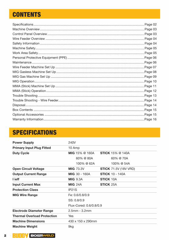
SPECIFICATIONSPower Supply
Primary Input Plug Fitted
Duty Cycle
Open Circuit Voltage
Output Current Range
I ieff
Input Current Max
Protection Class
MIG Wire Range
Electrode Diameter Range
Thermal Overload Protection
Machine Dimensions
Machine Weight
240V
10 Amp
MIG 15% @ 160A STICK 15% @ 140A
60% @ 80A 60% @ 70A
100% @ 62A 100% @ 54A
MIG 73.3V STICK 71.5V (18V VRD)
MIG 30 - 160A STICK 10 - 140A
MIG 9.3A STICK 10A
MIG 24A STICK 25A
IP21S
Fe: 0.6/0.8/0.9
SS: 0.8/0.9
Flux-Cored: 0.6/0.8/0.9
2.5mm - 3.2mm
Yes
430 x 150 x 290mm
9kg
3bossweld.com.au
7 8 9
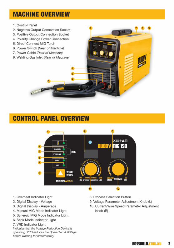
MACHINE OVERVIEW
CONTROL PANEL OVERVIEW
1. Control Panel2. Negative Output Connection Socket3. Positive Output Connection Socket4. Polarity Change Power Connection5. Direct Connect MIG Torch6. Power Switch (Rear of Machine)7. Power Cable (Rear of Machine)8. Welding Gas Inlet (Rear of Machine)
1. Overheat Indicator Light2. Digital Display - Voltage3. Digital Display - Amperage4. Manual MIG Mode Indicator Light5. Synergic MIG Mode Indicator Light6. Stick Mode Indicator Light7. VRD Indicator LightIndicates that the Voltage Reduction Device is operating. VRD reduces the Open Circuit Voltage before welding for added safety
8. Process Selection Button9. Voltage Parameter Adjustment Knob (L)10. Current/Wire Speed Parameter Adjustment
Knob (R)
1
2
3
45
MIG 150MANUAL
SYNERGIC
MMA
VRD
MIG
WELD MODE
AMPERAGEMIG 30MMA 101 40
160MANUAL VOLTAGE15V 24V
SYNERGIC VOLTAGE TRIM-2V +2V
1 2
9
3
10
4
5
6
7
8

4
WARNING! The device and packaging material are not toys! Children must not be allowed to play with the machine and its accessories. Plastic parts and packaging are choking risks for children.
• Open the packaging and remove the welder carefully. • Check that the delivery is complete. • If possible, store the packaging until the warranty period has expired.
The user of this welder is responsible for their own safety and the safety of others. It is important to read, understand and respect the contents of this user guide. When using this welder, basic safety precautions, including those in the following sections must be followed to reduce the risk of fire, electric shock and personal injury. Ensure that you have read and understood all of these instructions before using this welder. Persons who are not familiar with this user guide should not use this welder. Keep this booklet in a safe place for future reference.
TRAINING The operator should be properly trained to use the welding machine safely and should be informed about the risks relating to arc welding procedures. This user guide does not attempt to cover welding technique. Training should be sought from qualified / experienced personnel on this aspect, especially for any welds requiring a high level of integrity for safety.
SERIOUS FIRE RISK The welding process produces sparks, droplets of fused metal, metal projectiles and fumes. This constitutes a serious fire risk. Ensure that the area in which welding will be undertaken is clear of all inflammable materials. It is also advisable to have a fire extinguisher, and a welding blanket on hand to protect work surfaces.
SAFETY INFORMATION
WIRE FEEDER OVERVIEW1. Spool Holder2. Wire Inlet3. Wire Feed Tension Adjustment Knob4. Wire Feed Tension Arm5. Wire Drive Roller
1 3 42 5

5bossweld.com.au
• Ensure a clear, well lit work area with unrestricted movement for the operator. • The work area should be well ventilated, as welding emits fumes which can be dangerous. • Always maintain easy access to the ON/OFF switch of the welder, and the electrical mains supply • Do not expose the welder to rain and do not operate in damp or wet locations
Where welding must be undertaken in environments with increased risk of electric shock, confined spaces or in the presence of flammable or explosive materials, it is important that the environment be evaluated in advance by an “expert supervisor”. It is also recommended that welding in these circumstances be carried out in the presence of persons trained to intervene in emergencies.
AVOID ELECTRICAL CONTACT Use adequate electrical insulation with regard to the electrode, the work piece and any accessible earthed metal parts in the vicinity. Avoid direct contact with the welding circuit. The no load voltage between the work clamp and the electrode can be dangerous under certain circumstances.
Note: For additional protection from electric shock. It is recommended that this welder be used in conjunction with a residual current device (RCD) with rated residual current of 30MA or less.
In general the use of extension leads should be avoided. If used however, ensure that the extension lead used with the welder is of a suitable current rating and heavy duty in nature that MUST have an earth connection. If using the welder outdoors, ensure that the extension lead is suitable for outdoor use. Always keep extension leads away from the welding zone, moisture and any hot materials.
WELDING SURFACES • Do not weld containers or pipes that hold, or have held, flammable liquids or combustible gases
or pressure.• Do not weld on coated, painted or varnished surfaces as the coatings may ignite, or can give off
dangerous fumes.
WORK PIECE When welding, the work piece will remain at high temperature for a relatively long period. The operator must not touch the weld or the work piece unless wearing welding gloves. Always use pliers or tongs. Never touch the welded material with bare hands until it has completely cooled
VOLTAGE BETWEEN ELECTRODE HOLDERS OR TORCHES Working with more than one welding machine on a single work piece, or on work pieces that are connected, may generate a dangerous accumulation of no-load voltage between two different electrode holders or torches, the value of which may reach double the allowed limit.
Keep the welding cables, work clamp and electrode holder in good condition. Failure to do this can result in poor welding quality, which could be dangerous in structural situations.
Prior to use, check for breakage of parts and any other conditions that may affect operation of the welder. Any part of the welder that is damaged should be carefully checked to determine whether it will perform its intended function whilst being safe for the operator. Any part that is damaged should be properly repaired, or replaced by an authorised service centre.
IMPROPER USE It is hazardous to use the welding machine for any work other than that for which it was designed e.g. do not use welder for thawing pipes.
HANDLING Ensure the handle is correctly fitted. As welding machines can be heavy, always use safe lifting practices when lifting.
POSITION AND HANDLING To reduce risk of the machine being unstable / danger of overturning, position the welding machine on a horizontal surface that is able to support the machine weight. Operators MUST NOT BE ALLOWED to weld in raised positions unless safety platforms are used.
MACHINE SAFETY
WORK AREA SAFETY

6
WARNING! Before starting any cleaning, or maintenance procedures on the welding machine, make sure that it is switched OFF and disconnected from the mains supply.
There are no user serviceable parts inside the welder. Refer to a qualified service personnel if any internal maintenance is required. After use, wipe the welder down with a clean soft dry cloth.
Regular inspection of the supply cord is required. If damaged is suspected, must be immediately replaced by the manufacturer, its service agent or similarly qualified persons.
STORAGE/ TRANSPORT Store the welder and accessories out of children’s reach in a dry place. If possible store the welder in the original packaging. The appliance must be secured against falling or rolling over during transport.
MAINTENANCE
PERSONAL PROTECTIVE EQUIPMENT MUST BE USED WHEN MACHINE IS IN USE!
GLOVES AND PROTECTIVE CLOTHING Use protective gloves and fire resistant protective clothing when welding. Avoid exposing skin to ultraviolet rays produced by the arc.
WELDING HELMET Under no circumstances should the welder be operated unless the operator is wearing a welding helmet to protect the eyes and face. There is serious risk of eye damage if a helmet is not used. The sparks and metal projectiles can cause serious damage to the eyes and face. The light radiation produced by the arc can cause damage to eyesight, and burns to skin. Never remove the welding helmet whilst welding.
SAFETY GLASSES Always use appropriate safety glasses when brushing, chipping or grinding the slag from the weld.
OTHER PERSONS Ensure that other persons are screened from the welding arc and are at least 15 metres away from the work piece. Always ensure that the welding arc is screened from onlookers. Use screens if necessary or non-reflecting welding curtain. Do not allow children or animals access to the welding equipment or to the work area.
SWITCHING OFF When the operator has finished welding they must switch the welder off. DO NOT put the electrode holder down with the welder switched ON. When leaving the welder unattended, switch OFF and disconnect the welder from the electrical mains supply. Do not leave hot material unattended after welding.
FUMES & GASES ARE DANGEROUS Smoke and gas generated whilst welding or cutting can be harmful to people’s health. Welding produces fumes and gases. Breathing these fumes and gases can be hazardous to your health.
• Do not breathe the smoke and gas generated whilst welding or cutting, keep your head out of the fumes
• Keep the working area well ventilated, use fume extraction or ventilation to remove fumes and gases
• In confined or heavy fume environments always wear an approved air-supplied respirator. Welding fumes and gases can displace air and lower the oxygen level causing injury or death. Be sure the breathing air is safe.
• Do not weld in locations near de-greasing, cleaning, or spraying operations. The heat and rays of the arc can react with vapours to form highly toxic and irritating gases.
• Materials such as galvanized, lead, or cadmium plated steel, containing elements that can give off toxic fumes when welded. Do not weld these materials unless the area is very well ventilated, and or wearing an air supplied respirator.
PERSONAL PROTECTIVE EQUIPMENT (PPE)

7bossweld.com.au
MACHINE SET UP - MIG WIRE FEEDERWARNING! Ensure the machine is turned off and disconnected from the power supply before performing any of the following operations.
Fitting Wire Spool
1. Open side door of the machine.
2. Remove spool retaining nut and place spool of wire (1kg or 5kg) on spool hub.
Note: Ensure the wire feeds from underneath the spool into the wire feeder.
3. Replace spool retaining nut and tighten. Do not overtighten.
Threading and Tensioning Wire
4. Release the Wire Feed Tension Adjustment Knob by pulling it outwards.
5. Release the Wire Feed Tension Arm by pushing it upwards. Note: Check drive roller is matched to the wire size used.
6. Carefully feed wire through the inlet guide tube on to the drive roller and into the outlet guide tube until it passes through the Inlet Tube, and into the torch. Note: Hold wire to prevent the spool uncoiling.
7. Close the Wire Feed Tension Arm. Replace Wire Feed Tension Adjustment Knob and tighten. Do not overtighten.
Set Up MIG Torch
8. Remove the nozzle and the welding tip from the torch.
9. Plug the machine 10Amp input power lead into the wall socket, and switch to ON position.
10. Press and hold the trigger on the MIG Torch. This will feed the wire through the torch. Release trigger when wire appears at the end of the torch.
11. Switch machine power OFF.
12. Reinstall the welding tip over wire. Ensure contact tip size matches the size of the wire being used. Do not overtighten. Reinstall nozzle.
13. Trim wire to the end of the nozzle.
8
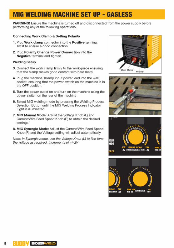
WARNING! Ensure the machine is turned off and disconnected from the power supply before performing any of the following operations.
Connecting Work Clamp & Setting Polarity
1. Plug Work clamp connector into the Positive terminal. Twist to ensure a good connection.
2. Plug Polarity Change Power Connection into the Negative terminal and tighten.
Welding Setup
3. Connect the work clamp firmly to the work-piece ensuring that the clamp makes good contact with bare metal.
4. Plug the machine 10Amp input power lead into the wall socket, ensuring that the power switch on the machine is in the OFF position.
5. Turn the power outlet on and turn on the machine using the power switch on the rear of the machine
6. Select MIG welding mode by pressing the Welding Process Selection Button until the MIG Welding Process Indicator Light is illuminated
7. MIG Manual Mode: Adjust the Voltage Knob (L) and Current/Wire Feed Speed Knob (R) to obtain the desired settings
8. MIG Synergic Mode: Adjust the Current/Wire Feed Speed Knob (R) and the Voltage setting will adjust automatically
Note: In Synergic mode, use the Voltage Knob (L) to fine tune the voltage as required. Increments of +/-2V
PolarityWork Clamp
MIG 150MANUAL
SYNERGIC
MMA
VRD
MIG
WELD MODE
AMPERAGEMIG 30MMA 101MANUAL VOLTAGE15V 24V
SYNERGIC VOLTAGE TRIM-2V +2VMIG 150MANUAL
SYNERGIC
MMA
VRD
MIG
WELD MODE
AMPERAGEMIG 30MMA 101 40
160MANUAL VOLTAGE15V 24V
SYNERGIC VOLTAGE TRIM-2V +2V
MIG WELDING MACHINE SET UP - GASLESS
9bossweld.com.au
PolarityWork Clamp
MIG 150MANUAL
SYNERGIC
MMA
VRD
MIG
WELD MODE
AMPERAGEMIG 30MMA 101MANUAL VOLTAGE15V 24V
SYNERGIC VOLTAGE TRIM-2V +2VMIG 150MANUAL
SYNERGIC
MMA
VRD
MIG
WELD MODE
AMPERAGEMIG 30MMA 101 40
160MANUAL VOLTAGE15V 24V
SYNERGIC VOLTAGE TRIM-2V +2V
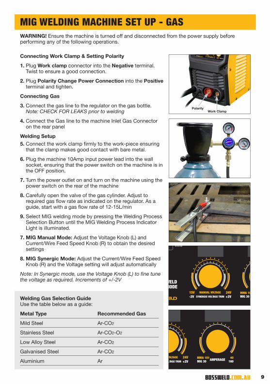
WARNING! Ensure the machine is turned off and disconnected from the power supply before performing any of the following operations.
Connecting Work Clamp & Setting Polarity
1. Plug Work clamp connector into the Negative terminal. Twist to ensure a good connection.
2. Plug Polarity Change Power Connection into the Positive terminal and tighten.
Connecting Gas
3. Connect the gas line to the regulator on the gas bottle. Note: CHECK FOR LEAKS prior to welding
4. Connect the Gas line to the machine Inlet Gas Connector on the rear panel
Welding Setup5. Connect the work clamp firmly to the work-piece ensuring
that the clamp makes good contact with bare metal.
6. Plug the machine 10Amp input power lead into the wall socket, ensuring that the power switch on the machine is in the OFF position.
7. Turn the power outlet on and turn on the machine using the power switch on the rear of the machine
8. Carefully open the valve of the gas cylinder. Adjust to required gas flow rate as indicated on the regulator. As a guide, start with a gas flow rate of 12-15L/min
9. Select MIG welding mode by pressing the Welding Process Selection Button until the MIG Welding Process Indicator Light is illuminated.
7. MIG Manual Mode: Adjust the Voltage Knob (L) and Current/Wire Feed Speed Knob (R) to obtain the desired settings
8. MIG Synergic Mode: Adjust the Current/Wire Feed Speed Knob (R) and the Voltage setting will adjust automatically
Note: In Synergic mode, use the Voltage Knob (L) to fine tune the voltage as required. Increments of +/-2V
Welding Gas Selection Guide Use the table below as a guide:
Metal Type Recommended Gas
Mild Steel Ar-CO2
Stainless Steel Ar-CO2-O2
Low Alloy Steel Ar-CO2
Galvanised Steel Ar-CO2
Aluminium Ar
MIG WELDING MACHINE SET UP - GAS

10
WARNING! Ensure appropriate PPE is worn, and work area is clear of hazards prior to operation.
Starting The Arc
1. Feed approximately 8-10mm of wire from the end of the torch (also called ‘stickout’) by pulling the trigger on the torch. Note: The shorter the stickout, the hotter the weld will be.
2. Touch the MIG wire to the work piece and raise it again approximately 1-2mm above the work piece.
3. Pull the trigger on the MIG torch, gas will flow and the wire will start to feed. When the wire touches the work piece the arc will strike and the wire will melt.
Forhand Pushing Technique
1. Hold the MIG torch at an angle of approximately 10° Note: Different angles will result in different weld bead shapes
2. Pull the trigger and slowly push the MIG torch away from you in the direction you wish to weld, ensuring the wire is pointing forward towards the leading edge of the weld.
Backhand/Pulling Technique
1. Hold the MIG torch at an angle of approximately 10° Note: Different angles will result in different weld bead shapes
2. Pull the trigger and slowly pull the MIG torch towards you in the direction you wish to weld, ensuring you keep the wire at the edge of the weld puddle.
Finishing the Weld
1. Release trigger and pull torch away from work piece quickly to break the arc.
2. Once the weld has cooled, clean weld by chipping or brushing away at slag to reveal the weld metal.
OPERATION - MIG WELDING
11bossweld.com.au
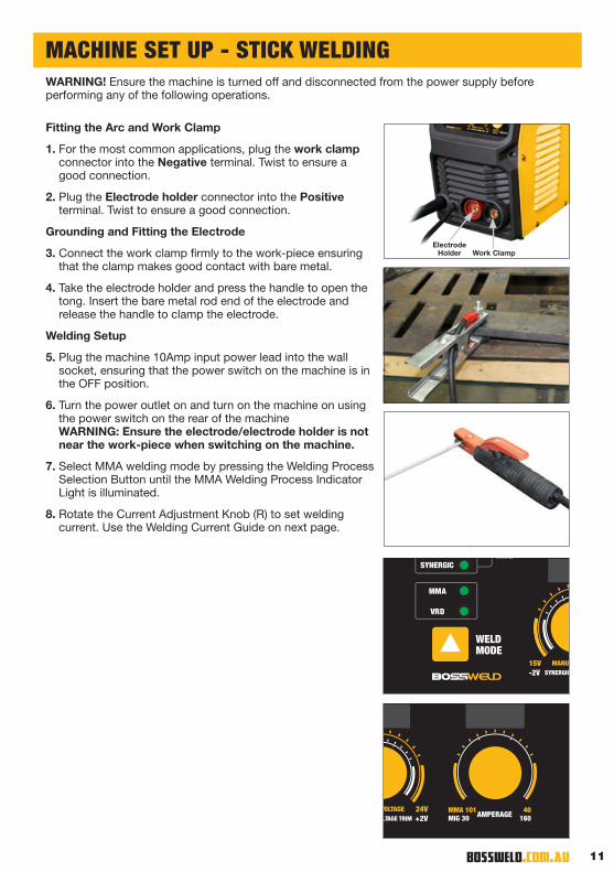
WARNING! Ensure the machine is turned off and disconnected from the power supply before performing any of the following operations.
Fitting the Arc and Work Clamp
1. For the most common applications, plug the work clamp connector into the Negative terminal. Twist to ensure a good connection.
2. Plug the Electrode holder connector into the Positive terminal. Twist to ensure a good connection.
Grounding and Fitting the Electrode
3. Connect the work clamp firmly to the work-piece ensuring that the clamp makes good contact with bare metal.
4. Take the electrode holder and press the handle to open the tong. Insert the bare metal rod end of the electrode and release the handle to clamp the electrode.
Welding Setup
5. Plug the machine 10Amp input power lead into the wall socket, ensuring that the power switch on the machine is in the OFF position.
6. Turn the power outlet on and turn on the machine on using the power switch on the rear of the machine WARNING: Ensure the electrode/electrode holder is not near the work-piece when switching on the machine.
7. Select MMA welding mode by pressing the Welding Process Selection Button until the MMA Welding Process Indicator Light is illuminated.
8. Rotate the Current Adjustment Knob (R) to set welding current. Use the Welding Current Guide on next page.
MACHINE SET UP - STICK WELDING
Electrode Holder Work Clamp
MANUAL
SYNERGIC
MMA
VRD
MIG
WELD MODE
MANUAL VOLTAGE15V 24VSYNERGIC VOLTAGE TRIM-2V +2VMIG 150
MANUAL
SYNERGIC
MMA
VRD
MIG
WELD MODE
AMPERAGEMIG 30MMA 101 40
160MANUAL VOLTAGE15V 24V
SYNERGIC VOLTAGE TRIM-2V +2V

12
Average Metal Thickness Electrode Size
1.0 - 2.0mm 2.0mm
2.0 - 5.0mm 2.6mm
5.0 - 8.0mm 3.2mm
8.0mm + 4.0mm
Electrode Selection Guide Electrode size selection will be determined by the thickness of the section being welded. Use the table below as a guide:
Welding Current Guide Welding current level is determined by the size of electrode. Use the table below as a guide:
Electrode Size/Gauge Welding Current
1.6mm 40-50 Amps
2.0mm 50-75 Amps
2.5mm 75-105 Amps
3.2mm 105-140 Amps
4.0mm 140-160 Amps
WARNING! Ensure appropriate PPE is worn, and work area is clear of hazards prior to operation.
Starting The Arc
1. Hold the Electrode above the work piece. In a smooth, quick motion, scratch the electrode across the work piece to create the arc.
Welding Work Piece
2. Hold the Electrode slightly above the work piece to maintain the arc, moving the electrode at an even speed to create an even weld distribution.
Finishing the Weld
3. Pull the electrode away from work piece quickly to break the arc.
4. Once the weld has cooled, clean the weld by chipping away at slag to reveal the weld metal.
MMA (STICK) WELDING OPERATION

13bossweld.com.au
Problem Suggested Remedy
Power indicator is not lit, fan does not work and no output current
1. Check that the welder is plugged into the 240V mains outlet and is switched on.
2. Check that the mains fuse or breaker has not operated.
3. Check that the main switch on the rear of the unit is in the on position.
Power indicator is lit, fan works, no output current
1. Check the welding cables are connected correctly.
2. Check the output connectors are not disconnected or damaged.
3. Check that the work clamp is connected securely to the work piece and that the contact point is clean of paint or rust.
Over temperature indicator is on, no output current
1. Duty cycle of the unit has been exceeded. Allow the unit to cool.
Output current is not stable.
1. Check mains voltage is constant.
2. Check the welding cable connectors are tight in the sockets.
3. Check the work clamp connection to the work piece.
4. Check the welding leads are not reversed.
Excessive Spatter 1. Check that the output polarity is correct for the type of electrode or wire being used
Porosity (Small cavities or holes resulting from gas pockets in weld metal)
1. Check that the correct gas is being used
2. Check the gas is connected; check hoses, gas valve and torch are not restricted and free of leaks. Set the gas flow between 10 - 15 l/min flow rate. Protect the welding zone from wind and drafts
3. Remove all moisture from base metal before welding
4. Remove materials like paint, grease, oil, and dirt, including mill scale from base metal
5. Use clean dry rust free wire. Do not lubricate the wire with oil, grease etc.
6. Check and tighten connection.
7. Clean or replace the gas nozzle
8. Replace the gas diffuser
Wire stubbing during welding
1. Bring the torch closer to the work and maintain stick out of 5-10mm
2. Increase the voltage
3. Decrease the wire feed speed
Lack of Fusion − failure of weld metal to fuse completely with base metal or a proceeding weld bead
1. Remove materials (paint, grease, oil, dirt, mill scale) from base metal
2. Select a higher voltage range and /or adjust the wire speed to suit
3. Keep the arc at the leading edge of the weld pool. Torch angle to work should be between 5 & 15° Direct the arc at the weld joint
4. Adjust work angle or widen groove to access bottom during welding, Momentarily hold arc on side walls if using weaving technique
5. Select a lower voltage range and /or adjust the wire speed to suit Increase travel speed
Lack of Penetration 1. Select a higher voltage range and /or adjust the wire speed to suit Reduce travel speed
2. Remove materials like paint, grease, oil, and dirt, including mill scale from base metal
TROUBLE SHOOTING

14
DISPOSING OF THE PACKAGING Recycling packaging reduces the need for landfill and raw materials. Reuse of the recycled material decreases pollution in the environment. Please recycle packaging where facilities exist. Check with your local council authority for recycling advice.
DISPOSING OF THE WELDER Welders that are no longer usable should not be disposed of with household waste but in an environmentally friendly way. Please recycle where facilities exist. Check with your local council authority for recycling advice.
Problem Suggested Remedy
No wire feed 1. Check that the MMA/MIG selector switch set to MIG position
Inconsistent / interrupted wire feed
1. Be sure to adjust the wire feed and voltage dials for MIG welding. The current dial is for MMA welding mode.
2. Select the correct polarity for the wire being used.
3. Incorrect wire speed: adjust the wire feed speed
4. Incorrect voltage: adjust the voltage setting
5. MIG Torch kinked: remove the kink, reduce the angle or bend
6. Tip worn/incorrect: replace the tip with correct size and type
7. Liner worn/clogged/incorrect size: try to clear the liner by blowing out with compressed air as a temporary cure, it is recommended to replace the liner regularly. Install the correct size liner.
8. Blocked/worn inlet guide: clear or replace the inlet guide tube
9. Misaligned in drive roller groove: reposition the wire into the groove of the drive roller
10. Incorrect/worn drive roller: fit the correct size/type drive roller. Replace drive roller
11. Drive roller pressure too high: reduce the drive roller pressure.
12. Tension high on wire spool hub: reduce the spool hub brake tension
13: Wire tangled/crossed: remove the spool untangle the wire or replace the wire.
14. Contaminated MIG wire: use clean dry rust free wire. Do not lubricate the wire with oil, grease etc.
TROUBLE SHOOTING - WIRE FEEDER
DISPOSAL

15bossweld.com.au
1. BUDDY MIG 150 Inverter Welder
2. MIG Torch
3. Work Clamp with Cable
4. Welding Cable with Electrode Holder
5. Gas Hose
6. Dual Stage Argon Regulator
7. Drive Rollers
8. Operating Manual (not pictured)
NOTE: The manufacturer’s liability shall be deemed void if the machine is modified in any way and the manufacturer shall therefore accept no liability for any damages arising as a result of modifications.
1. Bossweld Wideview Welding Helmet - Blaze (700199)
2. Bossweld Mild Steel MIG Wire - 0.8mm x 0.7kg (200003)
3. Bossweld Mild Steel MIG Wire - 0.8mm x 5kg (200004)
4. Bossweld Gasless GS MIG - 0.8mm x 0.9kg (200342)
5. Bossweld Gasless GS MIG - 0.8mm x 4.5kg (200343)
6. Bossweld 16" Black & Gold Welding Gloves (700010)
7. Bossweld General Purpose Electrodes - 2.0mm x 2kg (110110)
8. Bossweld General Purpose Electrodes - 2.6mm x 5kg (110140)
BOX CONTENTS
OPTIONAL ACCESSORIES
2 5
6
7
3
41
1
7 8
2 3 54
6
16
FAULTY GOODS SHOULD BE RETURNED IN THEIR ORIGINAL PACKAGING ALONG WITH ANY SUPPLIED ACCESSORIES.
1 YEAR WARRANTY
Your product is guaranteed against manufacturing workmanship or defect for a period of 12 months from the original date of purchase. This warranty covers manufacturing defects in materials, workmanship and finish under normal use. If a product is found to be defective we reserve the right
to repair or replace at our sole discretion.
No responsibility will be taken for products lost, damaged or mislaid whilst in transit.
To the extent permitted by law this warranty does not cover any indirect or consequential losses and our total liability, if any, shall be limited to the amount paid for the product by you to the retailer.
The benefits provided under this warranty are in addition to other rights and remedies which are available to you under Australian law.
PRIOR TO RETURNING YOUR PRODUCT FOR WARRANTY PLEASE CHECK THE TROUBLESHOOTING GUIDE IN THE PRODUCT INSTRUCTION MANUAL
FOR SERVICE SUPPORT PLEASE CALL (02) 8761 6500
IN ORDER TO MAKE A CLAIM UNDER WARRANTY YOU MUST RETURN THE PRODUCT TO
THE ORIGINAL PLACE OF PURCHASE ALONG WITH YOUR PURCHASE RECEIPT.
WARRANTY
WARRANTY EXCLUSIONS
The following actions will result in the warranty being void:
• Any damage caused by connection to a power supply or voltage other than specified for the machine
• Damage, faults or defects arising from misuse, abuse accidents or alterations
• Failure to perform maintenance or maintain good working condition of the machine or accessories as set out in the instruction manual
• If the machine is disassembled or tampered with in any way
• Fair wear and tear especially to cables, leads etc
• Consumable items such as electrode holders or clamps
This warranty is given by Dynaweld Industrial Supplies Pty Ltd
ABN: 17 050 731 756 Ph.1300 899 710
Australia (Head Office) 2/10 Jessica Place, Prestons, NSW, Australia, 2170


